kinematics and dynamics of an omnidirectional mobile
TRANSCRIPT

KINEMATICS AND DYNAMICS OF ANOMNIDIRECTIONAL MOBILE PLATFORM WITH
POWERED CASTER WHEELS
Maung ThanZaw† Denny Oetomo†
Marcelo H. Ang Jr. Ng Teck KhimNational University of Singapore
†Singapore Institute of Manufacturing Technology
Abstract
Mobile robots with omni-directional motion capabilities are very useful especially inmobile manipulation tasks and tasks in human environment. In this paper, we presentthe kinematics and dynamics of one class of omni-directional mobile robots that is drivenby a 2 axis powered caster wheels with non-intersecting axes of motions (caster wheelswith offset). Our derivation approach treats the each caster wheel as a serial manipulatorand the entire system as a parallel manipulator generated by several serial manipulatorwith a common end-effector, following the operational space formulation by Khatib
1 Introduction
Omnidirectional wheeled mobile robots have been an active research area overthe past three decades. The advantages over the legged mobile robots are the easeof manufacture, high pay load, high efficiency, and the ability to perform tasks incongested and narrow environment.
There are three types of wheels [1]: the conventional wheels, the omnidirectionalwheels, and the ball wheel. The conventional wheels are the wheels that we seeeveryday, such as those on the cars and trolleys. An omnidirectional wheel is adisk-like wheel with a multitude of conventional wheels mounted on its periphery.The ball wheel is one that’s shaped like a ball.
The ball wheel [2, 3] is difficult to implement as it is not possible to place anaxel through the ball without sacrificing the usable workspace. It is difficult totransmit power to drive the wheel. There is also the practical need of keeping itrobust from collected dust and dirt from the floor. There has been a lot of effortin the development of omnidirectional wheels [4, 5, 6]. Due to multiple number ofsmall rollers on the periphery of the wheel, an undesirable vibration often existsin the motion.
The conventional wheel is probably the simplest and most robust among thedesigns. However, not all conventional wheels are capable of providing omnidirec-
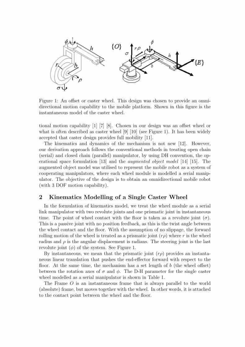
Figure 1: An offset or caster wheel. This design was chosen to provide an omni-directional motion capability to the mobile platform. Shown in this figure is theinstantaneous model of the caster wheel.
tional motion capability [1] [7] [8]. Chosen in our design was an offset wheel orwhat is often described as caster wheel [9] [10] (see Figure 1). It has been widelyaccepted that caster design provides full mobility [11].
The kinematics and dynamics of the mechanism is not new [12]. However,our derivation approach follows the conventional methods in treating open chain(serial) and closed chain (parallel) manipulator, by using DH convention, the op-erational space formulation [13] and the augmented object model [14] [15]. Theaugmented object model was utilised to represent the mobile robot as a system ofcooperating manipulators, where each wheel module is modelled a serial manip-ulator. The objective of the design is to obtain an omnidirectional mobile robot(with 3 DOF motion capability).
2 Kinematics Modelling of a Single Caster Wheel
In the formulation of kinematics model, we treat the wheel module as a seriallink manipulator with two revolute joints and one prismatic joint in instantaneoustime. The point of wheel contact with the floor is taken as a revolute joint (σ).This is a passive joint with no position feedback, as this is the twist angle betweenthe wheel contact and the floor. With the assumption of no slippage, the forwardrolling motion of the wheel is treated as a prismatic joint (rρ) where r is the wheelradius and ρ is the angular displacement is radians. The steering joint is the lastrevolute joint (φ) of the system. See Figure 1.
By instantaneous, we mean that the prismatic joint (rρ) provides an instanta-neous linear translation that pushes the end-effector forward with respect to thefloor. At the same time, the mechanism has a set length of b (the wheel offset)between the rotation axes of σ and φ. The D-H parameter for the single casterwheel modelled as a serial manipulator is shown in Table 1.
The Frame O is an instantaneous frame that is always parallel to the world(absolute) frame, but moves together with the wheel. In other words, it is attachedto the contact point between the wheel and the floor.
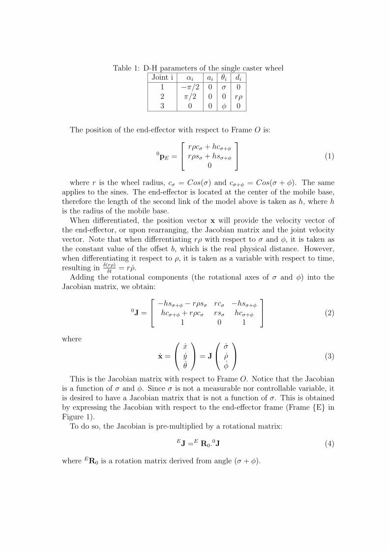
Table 1: D-H parameters of the single caster wheelJoint i αi ai θi di
1 −π/2 0 σ 02 π/2 0 0 rρ3 0 0 φ 0
The position of the end-effector with respect to Frame O is:
0pE =
rρcσ + hcσ+φ
rρsσ + hsσ+φ
0
(1)
where r is the wheel radius, cσ = Cos(σ) and cσ+φ = Cos(σ + φ). The sameapplies to the sines. The end-effector is located at the center of the mobile base,therefore the length of the second link of the model above is taken as h, where his the radius of the mobile base.
When differentiated, the position vector x will provide the velocity vector ofthe end-effector, or upon rearranging, the Jacobian matrix and the joint velocityvector. Note that when differentiating rρ with respect to σ and φ, it is taken asthe constant value of the offset b, which is the real physical distance. However,when differentiating it respect to ρ, it is taken as a variable with respect to time,resulting in δ(rρ)
δt= rρ.
Adding the rotational components (the rotational axes of σ and φ) into theJacobian matrix, we obtain:
0J =
−hsσ+φ − rρsσ rcσ −hsσ+φ
hcσ+φ + rρcσ rsσ hcσ+φ
1 0 1
(2)
where
x =
x
y
θ
= J
σ
ρ
φ
(3)
This is the Jacobian matrix with respect to Frame O. Notice that the Jacobianis a function of σ and φ. Since σ is not a measurable nor controllable variable, itis desired to have a Jacobian matrix that is not a function of σ. This is obtainedby expressing the Jacobian with respect to the end-effector frame (Frame {E} inFigure 1).
To do so, the Jacobian is pre-multiplied by a rotational matrix:
EJ =E R0.0J (4)
where ER0 is a rotation matrix derived from angle (σ + φ).
Figure 2: The common frame {B} is attached at the center of the mobile base. Allthe forward kinematics from each individual wheel module is transform to reflectthe end-effector at frame {B}.
The resulting Jacobian for a single wheel module with respect Frame {E} is:
EJ =
−bsφ rcφ 0
bcφ + h rsφ h1 0 1
(5)
3 Kinematics of Mobile Base
To find the Jacobian matrices of the rest of the wheels, it is only necessary toexpress them in the common frame (Frame {B}), which is attached to the centerof the mobile base:
BJi =B REi.EiJ (6)
where i denotes the caster wheel of interest, N is total number of wheel module inthe mobile base and BREi is the rotation matrix derived from angle β, as shownin Figure 2. This results in the Jacobian of wheel i with respect to common Frame{B} at the center of the mobile base:
BJi =
hsβi + bsβi+φi rcβi+φi +hsβi
hcβi + bcβi+φi −rsβi+φi hcβi
1 0 1
(7)
and
BJ−1i =
1rb
rsβi+φi rcβi+φi −rhcφi
bcβi+φi −bsβi+φi bhsφi
−rsβi+φi −rcβi+φi r(b + hcφ)
(8)
This derivation yields the same result as the geometric approach found in [12]and [14]. Note that the inverse always exists for rb �= 0.
3.1 Implementation Issue: Forward Kinematics
In the expression of the Jacobian matrix (Equation 7), we assume that we areable to obtain the joint variable σ for the purpose of forward kinematics. In thereal application, σ is not measurable.
In the inverse kinematics, however, it is possible to remove the σ component(see Equation 8). The inverse of Jacobian matrix without the σ component forany wheel i is obtained by simply removing the last row of BJ−1
i .
BJ−1i =
1rb
[rsβi+φi rcβi+φi −rhcφi
bcβi+φi −bsβi+φi bhsφi
](9)
which means [ρi
φi
]=B J−1
i
x
y
θ
(10)
The Jacobian inverse of all the individual wheel modules can be combined toform an augmented Jacobian inverse J−1
aug:
φ1
ρ1
φ2
ρ2
...
φN
ρN
=
J−11
J−12
...J−1
N
︸ ︷︷ ︸
.
x
y
θ
qaug = J−1aug. x
(11)
The forward kinematics can be obtained by solving for (x, y, θ)T from Equation11, which represents a 2N equations with 3 unknowns (N ≥ 2), for which ingeneral, there may not be a solution. But in this case, the wheel modules are heldtogether by physical constraints:
x
y
θ
= J1.
[φ1
ρ1
]= J2.
[φ2
ρ2
]= . . . = JN .
[φN
ρN
](12)
therefore an exact solution exist using the left pseudo inverse of J−1aug, i.e.:
JLPI = ((J−1aug)
T .J−1aug)
−1.(J−1aug)
T (13)
where
x
y
θ
= JLPI .
φ1
ρ1
φ2
ρ2
...
φN
ρN
(14)
Note that J−1LPI always exists for rb �= 0.
When the operational space velocity command vector is obtained from the con-trol law, it can be immediately used in Equation 11 to produce the joint ratecommand vector to be sent out to the high level controller for each joint to obtainthe desired motion.
4 Kinematic Analysis
The aim of kinematic analysis is to determine the optimal design parameters thatexert, as much as possible, equal effort in joint space to produce any motion in taskspace. In a serial manipulator, this is often reflected in a manipulability ellipsoid[16] at the end-effector. This is directly related to the singularity issues whereby theend-effector loses the ability to move in certain direction (the degenerate direction).
In the case of caster wheel in a mobile base system, singularity is not an issue,as it is already shown above Equation 8 that the inverse of the Jacobian matrixalways exists, as long as r �= 0 and b �= 0. The exception to this would be whenpassive joints are included in the system and only 3 joints are actuated to producemotion in 2D plane.
A manipulability ellipsoid, or more appropriately, the maneuverability ellipsoid,shows the velocity generated in task space with bounded joint velocities. Pleasenote that it is not appropriate to use the Jacobian matrix in Equation 7, becauseit still reflects the contribution of the imaginary joint σ. The appropriate anal-ysis should be performed on the J−1 matrix without the contribution of σ (fromEquation 9) or the Jacobian matrix obtained from Equation 13.
The joint space of a caster wheel, however, only contains two joints: the steerand the drive and it is obvious that when the mobile base diameter is much largerthan the wheel radius, then one rotation in steer angle produces a much largermotion than one revolution of the wheel.
5 Dynamic Modelling
The caster wheel is treated as a serial link manipulator, each subjected to:
τττ = A(q)q + b(q, q) + g(q) (15)
where τττ is the torque to be sent to joint actuators, A is the inertia matrix, b isvector that contains the Coriolis and Centrifugal effects, and g is the gravitationaleffect on the joints.
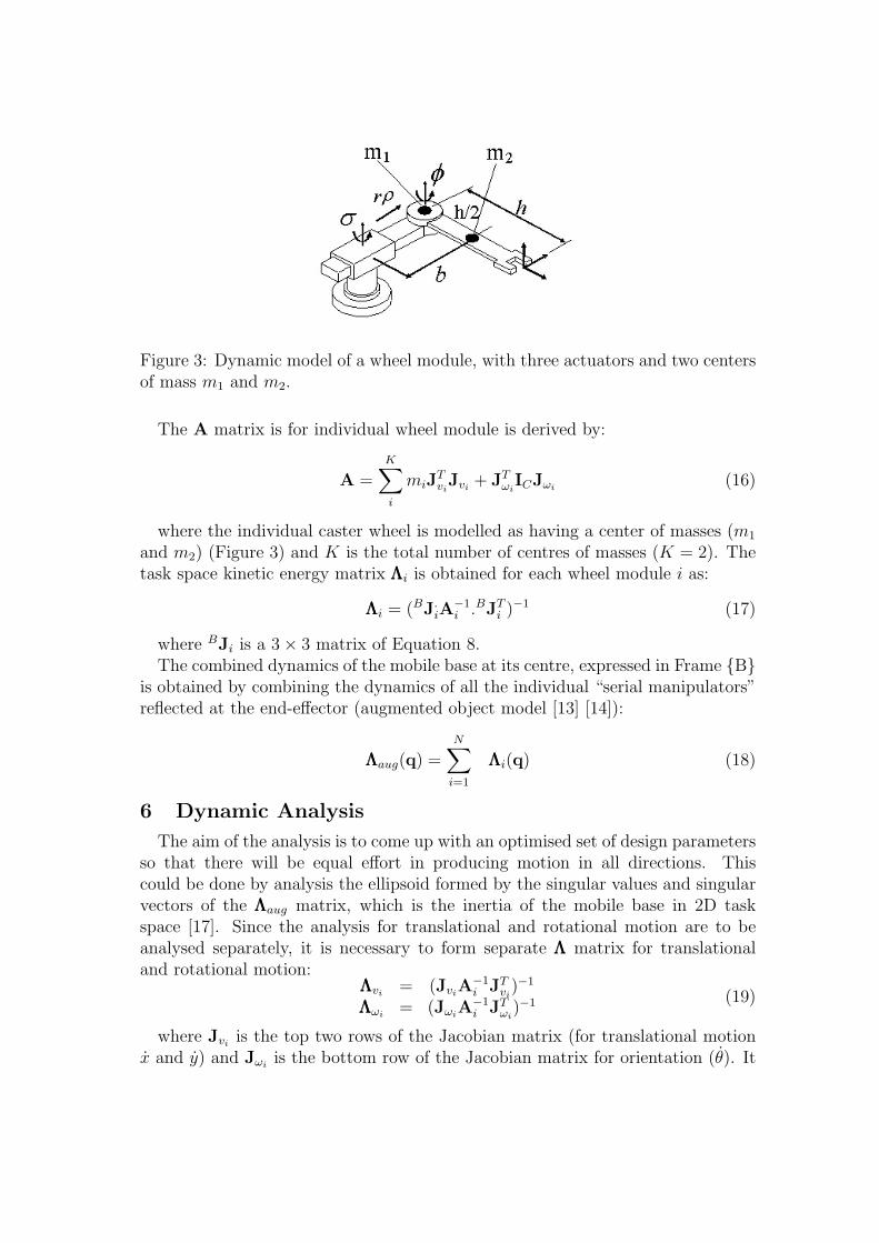
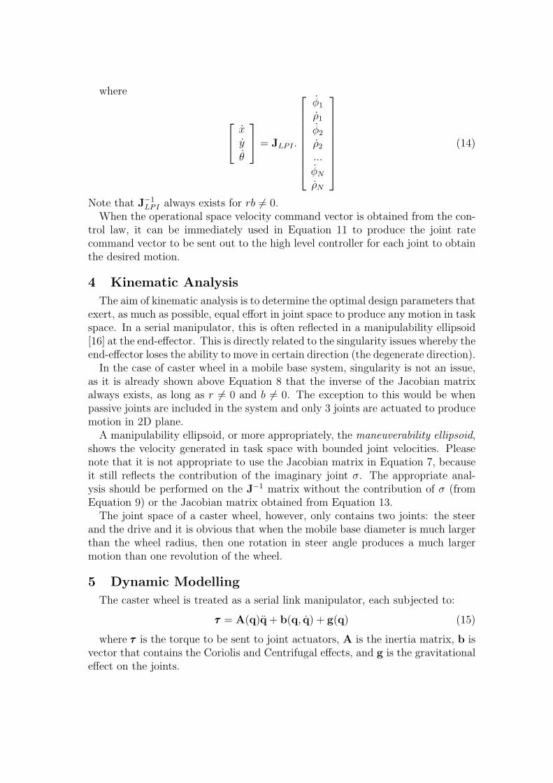
Figure 3: Dynamic model of a wheel module, with three actuators and two centersof mass m1 and m2.
The A matrix is for individual wheel module is derived by:
A =K∑i
miJTviJvi
+ JTωiICJωi
(16)
where the individual caster wheel is modelled as having a center of masses (m1
and m2) (Figure 3) and K is the total number of centres of masses (K = 2). Thetask space kinetic energy matrix ΛΛΛi is obtained for each wheel module i as:
ΛΛΛi = (BJ.iA
−1i .BJT
i )−1 (17)
where BJi is a 3 × 3 matrix of Equation 8.The combined dynamics of the mobile base at its centre, expressed in Frame {B}
is obtained by combining the dynamics of all the individual “serial manipulators”reflected at the end-effector (augmented object model [13] [14]):
ΛΛΛaug(q) =N∑
i=1
ΛΛΛi(q) (18)
6 Dynamic Analysis
The aim of the analysis is to come up with an optimised set of design parametersso that there will be equal effort in producing motion in all directions. Thiscould be done by analysis the ellipsoid formed by the singular values and singularvectors of the ΛΛΛaug matrix, which is the inertia of the mobile base in 2D taskspace [17]. Since the analysis for translational and rotational motion are to beanalysed separately, it is necessary to form separate ΛΛΛ matrix for translationaland rotational motion:
ΛΛΛvi= (Jvi
A−1i JT
vi)−1
ΛΛΛωi= (Jωi
A−1i JT
ωi)−1 (19)
where Jviis the top two rows of the Jacobian matrix (for translational motion
x and y) and Jωiis the bottom row of the Jacobian matrix for orientation (θ). It
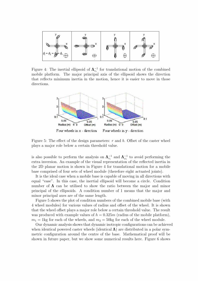
Figure 4: The inertial ellipsoid of ΛΛΛ−1vi
for translational motion of the combinedmobile platform. The major principal axis of the ellipsoid shows the directionthat reflects minimum inertia in the motion, hence it is easier to move in thosedirections.
Figure 5: The effect of the design parameters: r and b. Offset of the caster wheelplays a major role below a certain threshold value.
is also possible to perform the analysis on ΛΛΛ−1vi
and ΛΛΛ−1ωi
to avoid performing theextra inversion. An example of the visual representation of the reflected inertia inthe 2D planar motion is shown in Figure 4 for translational motion for a mobilebase comprised of four sets of wheel module (therefore eight actuated joints).
It is the ideal case when a mobile base is capable of moving in all directions withequal “ease”. In this case, the inertial ellipsoid will become a circle. Conditionnumber of ΛΛΛ can be utilised to show the ratio between the major and minorprincipal of the ellipsoids. A condition number of 1 means that the major andminor principal axes are of the same length.
Figure 5 shows the plot of condition numbers of the combined mobile base (with4 wheel modules) for various values of radius and offset of the wheel. It is shownthat the wheel offset plays a major role below a certain threshold value. The resultwas produced with example values of h = 0.325m (radius of the mobile platform),m1 = 1kg for each of the wheels, and m2 = 50kg for each of the wheel module.
Our dynamic analysis shows that dynamic isotropic configurations can be achievedwhen identical powered caster wheels (identical ΛΛΛ) are distributed in a polar sym-metric configuration around the centre of the base. Mathematical proof will beshown in future paper, but we show some numerical results here. Figure 6 shows
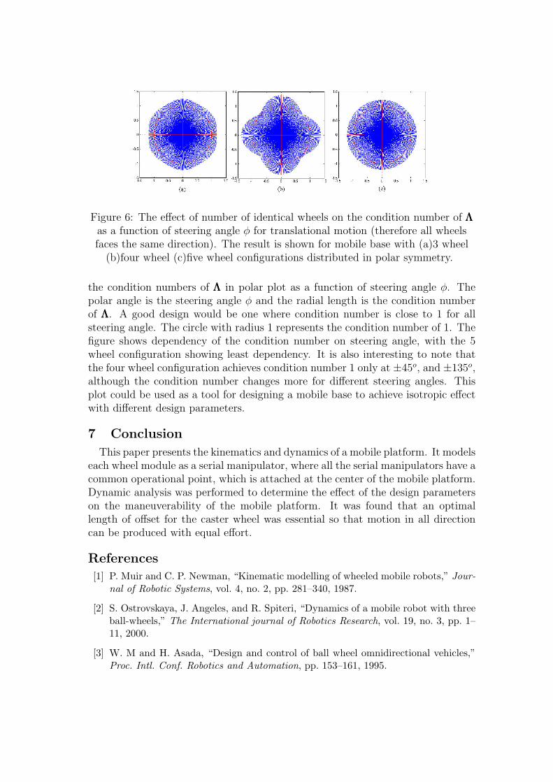
Figure 6: The effect of number of identical wheels on the condition number of ΛΛΛas a function of steering angle φ for translational motion (therefore all wheelsfaces the same direction). The result is shown for mobile base with (a)3 wheel
(b)four wheel (c)five wheel configurations distributed in polar symmetry.
the condition numbers of ΛΛΛ in polar plot as a function of steering angle φ. Thepolar angle is the steering angle φ and the radial length is the condition numberof ΛΛΛ. A good design would be one where condition number is close to 1 for allsteering angle. The circle with radius 1 represents the condition number of 1. Thefigure shows dependency of the condition number on steering angle, with the 5wheel configuration showing least dependency. It is also interesting to note thatthe four wheel configuration achieves condition number 1 only at ±45o, and ±135o,although the condition number changes more for different steering angles. Thisplot could be used as a tool for designing a mobile base to achieve isotropic effectwith different design parameters.
7 Conclusion
This paper presents the kinematics and dynamics of a mobile platform. It modelseach wheel module as a serial manipulator, where all the serial manipulators have acommon operational point, which is attached at the center of the mobile platform.Dynamic analysis was performed to determine the effect of the design parameterson the maneuverability of the mobile platform. It was found that an optimallength of offset for the caster wheel was essential so that motion in all directioncan be produced with equal effort.
References
[1] P. Muir and C. P. Newman, “Kinematic modelling of wheeled mobile robots,” Jour-nal of Robotic Systems, vol. 4, no. 2, pp. 281–340, 1987.
[2] S. Ostrovskaya, J. Angeles, and R. Spiteri, “Dynamics of a mobile robot with threeball-wheels,” The International journal of Robotics Research, vol. 19, no. 3, pp. 1–11, 2000.
[3] W. M and H. Asada, “Design and control of ball wheel omnidirectional vehicles,”Proc. Intl. Conf. Robotics and Automation, pp. 153–161, 1995.
[4] L. Ferriere, B. Raucent, and G. Campion, “Design of omnidirectional robot wheels,”Proc. Intl. Conf. on Robotics and Automation, vol. 4, pp. 3664–3670, 1996.
[5] W. La, T. Koogle, D. L. Jaffe, and L. Leifer, “Toward total mobility: an omnidi-rectional wheelchair,” Proc. 4th RESNA, pp. 75–77, 1981.
[6] I. Paromtchik and U. Rembold, “Practical approach to motion generation and con-trol for an omnidirectional mobile robot,” Proc. IEEE Intl. Conf. Robotics andAutomation, vol. 4, pp. 2790–2795, 1994.
[7] J. Alexander and J. Maddocks, “On the kinematics of wheeled mobile robots,” TheInternational Journal of Robotics Research, vol. 8, no. 5, pp. 15–27, 1989.
[8] S. Ostrovskaya, J. Angeles, and R. Spiteri, “Nonholonomic sysmtes revisited withinthe framework of analytical mechanisms,” Appl Mech Rev, vol. 51, no. 7, pp. 415–433, 1998.
[9] M. Wada and S. Mori, “Holonomic and omnidirectional vehicle with conventionaltires,” Proc. IEEE Intl. Conf. Robotics and Automation, vol. 1, pp. 265–270, 1996.
[10] L. Ferriere, B. Raucent, and A. Fournier, “Design of a mobile robot equippedwith off-centered orientable wheels,” Proc. of the Research Workshop of ERNET,pp. 127–136, 1996.
[11] G. Campion, G. Bastin, and B. D’Andrea-novel, “Structural properties and clasifi-cation of kinematic and dynamic models of wheeled mobile robots,” IEEE Trans-actions on Robotics and Automation, vol. 12, pp. 47–62, February 1996.
[12] B.-J. Yi and W.-K. Kim, “The kinematics for redundantly actuated omnidirectionalmobile robots,” Journal of Robotic Systems, vol. 19, no. 6, pp. 255–267, 2002.
[13] O. Khatib, “A unified approach for motion and force control of robot manipulators:The operational space formulation,” IEEE J. Robotics and Automation, vol. RA-3,no. 1, pp. 43–53, 1987.
[14] R. Holmberg, “Design and development of powered-caseter holonomic mobilerobots.” PhD. Dissertation, August 2000. Stanford University.
[15] D. Williams and O. Khatib, “The virtual linkage: A model for internal forces inmulti-grasp manipulation,” Proc. IEEE International Conference on robotics andAutomation, vol. 3, pp. 1025–1030, 1993.
[16] T. Yoshikawa, “Manipulability of robotic mechanisms,” Intl. J. Robotics Research,vol. 4, pp. 3–9, Summer 1985.
[17] H. Asada, “A geometrical representation of manipulator dynamics and its appli-cation to arm design,” Trans ASME, J. Dyn. Syst., Meas and Control,, vol. 105,pp. 131–135, 1983.