kicker test atatft atf - home · ilc agenda (indico) · kicker test atatft atf junji urakawa (kek)...
TRANSCRIPT

Kicker Testt ATFat ATF
Junji Urakawa (KEK)forfor
ATF International Collaboration2008/3/4 Sendai-GDE 2008 1
ATF International Collaboration

ATFAccelerator Test Facility
ILC lik b f ATF2
ATF-II
ILC like beam for ATF2
EXTDamping RingDamping Ring
2008/3/4 Sendai-GDE 2008 2Photo-cathode RF Gun which can generate 20 bunches/pulse.
1.3GeV Linac

ATF (Accelerator Test Facility)Pulsed Laser Wire scannerBeam size monitor
Cavity BPMnm resolutionEnergy: 1.28 GeV
Extraction lineBeam supply for BDS Exp., instrumentation R&D
beam position monitorElectron bunch: 2x10¹⁰ e/bunch1 ~ 20 bunches/train3 trains/ring
Damping Ring
CSR
3 trains/ring1.56 Hz
εx/y ~ 1.5nm/4pmLow emittance beam generation
Study on beam instabilityInstrumentation Development
Fast kickerFast kickerStrip-line fast kicker development
XSR
2008/3/4 Sendai-GDE 2008 3
Photo-cathode RF gun S-band Linac

Beam Kick test of Fast kicker (KEK LLNL SLAC LBNL LNF)Beam Kick test of Fast kicker (KEK LLNL SLAC LBNL LNF)(KEK, LLNL, SLAC, LBNL,LNF)(KEK, LLNL, SLAC, LBNL,LNF)
2005-2006Ri ti <3Rise time<3 nsEvaluation on kick angle fromcoherent beam oscillation inATF damping ring2007〜2008Design andDesign and demonstration for real beam extraction.
Rise time = 3.2ns(1%~100%)Fall time = 4.0ns(100% 1%)
Pulse Train (3000 pulses)output from FID Pulser
2008/3/4 Sendai-GDE 2008 4
(100%~1%)from FID PulserBurst pulses(3MHz, 3000pulses)

Design and beam test for strip-line fast kicker experiment
Present kicker stability (Pulse magnet kicker system)
2 >2 >
1) Ch1: 10 mV 50 ns
308ns pulse width 10kV 1ns:rise time, fast
Multi-bunch beam supply to ATF Ext0 2
0
0.2
(Single bunch) x 3 Train Extraction
154ns spacing
1↓1↓2) Ch1: 100 mV 50 ns Thy. Current 1 Amplitude Droop at 300ns Pulse power supplies
supply to ATF-Ext.60 bunches with 154 ns spacing.30 bunches with 308 ns
-0.8
-0.6
-0.4
-0.2
BP
M S
igna
l
2008/3/4 Sendai-GDE 2008 5
spacing.
-1.2
-1
-600 -400 -200 0 200 400 600 800
Time (nsec)
3 bunches, 154ns spacing

Future Kicker Tests at ATFNew septum and a "slow" orbit bump wouldNew septum and a slow orbit bump would allow fast extraction using two 30 cm strip lines, driven by ±10 kV pulsers.y p
Bump orbit+10 kV
Bump orbit
-10 kV
30 cm
The length of each strip-line is limited by the rise and fall time specifications: the maximum length is approximately 30 cm.Each strip-line is driven by two pulsers operating at ±10 kV providing a voltage
2008/3/4 Sendai-GDE 2008 6
Each strip-line is driven by two pulsers operating at ±10 kV, providing a voltage between the electrodes of 20 kV. Beam extraction at the end of 2008

2008/3/4 Sendai-GDE 2008 7

Beam Kick test of ILC Fast kicker (KEK,LLNL,SLAC,LNF,LBNL,DESY, FID)
This experiment almost shows perfectki k i i l
rise time improvement by using waveform compensator.
kick timing control.
2008/3/4 Sendai-GDE 2008 8
3 ns -> 2.2 nsPulse Train (3000 pulses )Output from FID Pulser

Multi-bunch Turn-by-turn monitor
The beam blowup at tail bunches was measured by
T. Naito (KEK)
5 0 10-11Vertical Emittance of Multibunch
Y_emittance(00mode, 1.6E9intensity)Y_emittance(00mode, 3.7E9intensity)Y_emittance(01mode, 6.3E9intensity)
p ythe laser wire in ATF, which is assumed coming fromFII effect. In order to observe the individual beamoscillation in the multi-bunch beam, multi-bunchturn-by-turn monitor has been developed. Thismonitor consists of front end circuits(amplifier and
3.0 10-11
4.0 10-11
5.0 10
ce o
f eac
h bu
nch
9
6.3x10⁹
( pfilter) and DPO7254 scope. The scope can store thewaveform up to 2ms with 100ps time resolution.
0.0 100
1.0 10-11
2.0 10-11
Vert
ical
Em
ittan
c
1.6x10⁹
3.7x10⁹
GLC Design
When one bunch from many bunches iskicked we hope other bunches have 0 5 10 15 20
Bunch Numberkicked, we hope other bunches have almost no oscillation.
1st
Th li i lt h th diff t ill ti
2nd
2008/3/4 Sendai-GDE 2008 9
The preliminary results shows the different oscillationamplitude of the tune-X and the tune-Y for the 1st and 2ndbunches at just after injection. Tune-X Tune-Y

Multi-bunch Beam extraction design for Future Kicker Tests at ATF
Multi-bunch Beam extraction by usingy gstrip-line kickers and pulse bump orbitsystem was designed, which can extractup to 60 bunches with 154ns bunchspacing. The space for installation of thestrip-line kicker is not enough at the ATFp gseptum region. So the kick angle of thestrip-line kicker is not enough to makethe beam extraction orbit. We need asmall septum.
A new design uses slow bumpmagnets and a thin septum magnetCirculate g p gto help making the extraction orbit.This design makes a bump orbitafter beam damping, then eachbeam is extracted bunch-by-bunchby the strip-line kickers.
Beam orbit
y pNew septum and a "slow" orbit bump would allow fast extraction using two 30 cm strip lines, driven by ±10 kV pulsers.
Extracted Beam orbit
2008/3/4 Sendai-GDE 2008 10
by ±10 kV pulsers.
Designed by T.Nato(KEK)

Electric and magnetic field lines of theElectric and magnetic field lines of the strip-line electrode
El t d di t 12Electrode distance:12mmChamber diameter : 24mmImpedance :50ohmMax field at 10kV : 4.7MV/m
2008/3/4 Sendai-GDE 2008 11

Replacement from kicker magnet to strip-line kicker
A 60cm long kicker magnet makes a 4.6mrad kick angle. Two strip-line kickers can make only1.3mrad kick angle. It is not enough for the kick angle to extract the beam
2008/3/4 Sendai-GDE 2008 12
It is not enough for the kick angle to extract the beam.
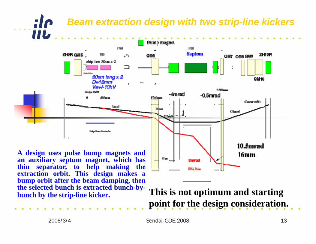
Beam extraction design with two strip-line kickers
A design uses pulse bump magnets andan auxiliary septum magnet, which hasthin separator, to help making thethin separator, to help making theextraction orbit. This design makes abump orbit after the beam damping, thenthe selected bunch is extracted bunch-by-bunch by the strip-line kicker. This is not optimum and starting
2008/3/4 Sendai-GDE 2008 13
point for the design consideration.

Timing chart of 60(30) bunches beam extraction
Th b bit i d ll i d ft ll fThe bump orbit is gradually increased after all ofthe bunches have been damped. The strip-linekicker kicks out the beams at the timing of theflat-top of the bump orbit. The beams are
t t d l b h t i hi h iextracted as one long bunch train, which is a10micro-sec long with 154ns (or 308 ns) spacing.
2008/3/4 Sendai-GDE 2008 14

Detail of power supply controlTo avoid the beam loss at the injection timing by the bump orbitTo avoid the beam loss at the injection timing by the bump orbit,the current control starts from 200ms after injection, whichcorrespond to about three damping time. The current ramp needs120ms to keep the beam orbit. The beam is extracted at the flat-ptop of the current.
Beam Injection
Bump orbit startBump orbit start
Current control
Magnet currentMagnet current
2008/3/4 Sendai-GDE 2008 15
100ms/div

Local bump by using present magnets and DC power supplies
The aperture survey was carried out byusing present magnets and DC power
li Th i d b h i ht isupplies. The required bump height is5mm to separate the extraction beam andthe circular beam.
2008/3/4 Sendai-GDE 2008 16

Beam extraction design with two strip-lines
Bump orbit
The bump orbit is optimizedto eliminate the aperturelimit at the septum area.
2008/3/4 Sendai-GDE 2008 17

Required magnet parameters
1. Magnets(not yet designed)• Steering magnets• Steering magnets
• Bending angle: 9mrad(max)• Effective length 100mm• 0.4T(max)
• Septum magnet • Bending angle: 14mradg g• 1000AT, 0.6m, 1 turn coil
2. Power supplies• Steering magnets 50A(MAX) 10V(pulse)• Steering magnets - 50A(MAX), 10V(pulse)• Septum magnet - 1000A, 1V(DC)
2008/3/4 Sendai-GDE 2008 18

Proposed Schedule
•4 sets of 10kV fast pulsers order and test until end of 2007
•Fabrication strip line electrodes until end of March 2008•Fabrication strip-line electrodes until end of March 2008
•Fabrication bump magnets and pulse PS until end of 2007
•Pulse bump magnet test until end of March 2008
•Fabrication Septum magnet until end of June 2008
•Installation strip-line electrodes and septum Summer 2008
•Beam test Autumn 2008
Strip-line electrode from LNF and fast pulse power supply fromLLNL and SLAC in 2008 or 2009 will be expected.
2008/3/4 Sendai-GDE 2008 19
p

Kicker Specifications
eEA
kLV x
γmax,2=×
The kickers will consist of strip-lines fed by ultra-fast, high-voltage pulsers. The integrated voltage required is determined by the acceptance specification:pwhere V is the voltage between the strip-lines, L is the strip-line length, kis a geometry factor (~ 0.7) determined by the strip-line shape, Amax (~ 0.09 m for injected positrons) is the maximum betatron amplitude, E is the beam energy and γ is the relativistic factor.
Integrated voltage > 132 kV-mRise and fall times < 3 nsRise and fall times < 3 nsRepetition rate 5.5 MHzPulse length 970 µs
2008/3/4 Sendai-GDE 2008 20
Pulse length 970 µsStability < 0.1%
Kicker Systems
There is a continuing R&D program to develop a pulser that meets the specifications for amplitude rise and fall time repetition rate and stabilityspecifications for amplitude, rise and fall time, repetition rate, and stability.Several technologies look promising, including:
fast ionization dynistor (FID);drift step recovery diode (DSRD);"inductive adder" (MOSFET).
There is a commercial FID device available that comes close to meeting the gspecifications.
A prototype with modified architecture, which could meet most of the ILC specifications, is in development; a version for bench testing is expected p p g pby the end of 2009.
Modification of ATF extraction system to allow fast extraction of individual bunches from a train is planned for late 2008.
2008/3/4 Sendai-GDE 2008 21
p