kh dsp - georg neumann gmbh · the kh 80 dsp represents the latest in acoustic and electronic...
TRANSCRIPT

georg neumann gmbh · Leipziger str. 112 · 10117 berLin · germany teL +49 (0)30 / 41 77 24-0 · fax -50 · [email protected] · www.neumann.com
pubL. 03/17
KH 80 DSP
Instruction ManuaL

KH 80 DSP | 2
The KH 80 DSP studio monitor . . . . . . . . . . . . . . . . . . . . . . . . . . . . . . . . . . . . . . . . . . . . . . 3
Delivery includes . . . . . . . . . . . . . . . . . . . . . . . . . . . . . . . . . . . . . . . . . . . . . . . . . . . . . . . . . . 3
About this manual . . . . . . . . . . . . . . . . . . . . . . . . . . . . . . . . . . . . . . . . . . . . . . . . . . . . . . . . . . 3
Product overview . . . . . . . . . . . . . . . . . . . . . . . . . . . . . . . . . . . . . . . . . . . . . . . . . . . . . . . . . . 4
Installing and connecting the KH 80 DSP . . . . . . . . . . . . . . . . . . . . . . . . . . . . . . . . . . . . . 5Preparing the loudspeakers . . . . . . . . . . . . . . . . . . . . . . . . . . . . . . . . . . . . . . . . . . . . 5Preparing the room . . . . . . . . . . . . . . . . . . . . . . . . . . . . . . . . . . . . . . . . . . . . . . . . . . . . 5Positioning the loudspeakers . . . . . . . . . . . . . . . . . . . . . . . . . . . . . . . . . . . . . . . . . . .6Connecting audio signals . . . . . . . . . . . . . . . . . . . . . . . . . . . . . . . . . . . . . . . . . . . . . . . 7Connecting network cables . . . . . . . . . . . . . . . . . . . . . . . . . . . . . . . . . . . . . . . . . . . . .8Connecting/disconnecting the KH 80 DSP to/from the mains power supply . . . . . . . . . . . . . . . . . . . . . . . . . . . . . . . . . . . . . . . . . . . . . . . .8
Configuring and using the KH 80 DSP . . . . . . . . . . . . . . . . . . . . . . . . . . . . . . . . . . . . . . . . 9Switching the KH 80 DSP on/off . . . . . . . . . . . . . . . . . . . . . . . . . . . . . . . . . . . . . . . . .9Functionality of the Neumann logo . . . . . . . . . . . . . . . . . . . . . . . . . . . . . . . . . . . . . 10SETTINGS switch . . . . . . . . . . . . . . . . . . . . . . . . . . . . . . . . . . . . . . . . . . . . . . . . . . . . . 11Resetting the KH 80 DSP . . . . . . . . . . . . . . . . . . . . . . . . . . . . . . . . . . . . . . . . . . . . . . 11Firmware update . . . . . . . . . . . . . . . . . . . . . . . . . . . . . . . . . . . . . . . . . . . . . . . . . . . . . 11Adjusting the frequency response using the backpanel controls . . . . . . . . . . . . 12Adjusting the acoustic level . . . . . . . . . . . . . . . . . . . . . . . . . . . . . . . . . . . . . . . . . . . 12
Cleaning and maintaining the KH 80 DSP . . . . . . . . . . . . . . . . . . . . . . . . . . . . . . . . . . . . 13
Troubleshooting . . . . . . . . . . . . . . . . . . . . . . . . . . . . . . . . . . . . . . . . . . . . . . . . . . . . . . . . . . 13
Specifications . . . . . . . . . . . . . . . . . . . . . . . . . . . . . . . . . . . . . . . . . . . . . . . . . . . . . . . . . . . . 13
Acoustical measurements and block diagram . . . . . . . . . . . . . . . . . . . . . . . . . . . . . . . . . 14
Accessories . . . . . . . . . . . . . . . . . . . . . . . . . . . . . . . . . . . . . . . . . . . . . . . . . . . . . . . . . . . . . . 14
Installation angles . . . . . . . . . . . . . . . . . . . . . . . . . . . . . . . . . . . . . . . . . . . . . . . . . . . . . . . . 15
Contents
EN
KH 80 DSP | 3
The KH 80 DSP studio monitorThank you for purchasing a Neumann studio monitor . The KH 80 DSP features a Mathemati-cally Modeled Dispersion™ Waveguide (MMD™), DSP acoustical controls, control via standard IP networks and an extensive range of mounting hardware . This allows the loudspeaker to be used in diverse acoustical conditions, with any source equipment and in a wide variety of physical locations . The KH 80 DSP represents the latest in acoustic and electronic simulation and measurement technologies to ensure the most accurate sound reproduction possible .
Depending on the size, Neumann’s two-way loudspeaker systems are designed for use as near field monitors or as rear loudspeakers in larger multi-channel systems . They can be used in project, music, broadcast, and post production studios for tracking, mixing, and mastering .
Delivery includes1 KH 80 DSP
4 Self-adhesive feet
1 Safety Guide
1 Supplement “Getting Started Quickly”
Delivery also includes European, UK or US mains cables
About this manualThis operating manual describes the physical setup and autonomous operation of the KH 80 DSP . For information about using the KH 80 DSP in a network with the Neumann .Control software please refer to the software help .
Some of the advantages of exploring Neumann .Control are:
• More extensive acoustical controls for more accurate audio reproduction
• System-wide control such as volume control, soloing and muting
• Rapid system re-purposing
When released, to download the app for Android or iOS tablets go to the Google Play Store or Apple App Store and search for “Neumann .Control” .
When released, to download the software for PC or Mac go to www .neumann .com and find the download section in the KH 80 DSP product page .
Note that imperial dimensions are approximate .
EN

KH 80 DSP | 4
Product overview
1
2 2
1 Neumann logo• for information on the functionality
of the Neumann logo refer to chapter “Functionality of the Neumann logo”
2 Bass reflex ports
3
4
5
7
6
3 Threaded inserts (M6) for Neumann mounting hardware
4 On/off switch
5 RJ-45 socket for network control
6 Cooling vents
7 Control switches
8
9 8 Mains socket
9 XLR/Jack analog input socket
Front panel
Back panel
Bottom
EN

KH 80 DSP | 5
Installing and connecting the KH 80 DSPCAUTIONDanger of injury and material damage due to tipping/dropping of the product!
If improperly mounted, the product and/or the mounting hardware (e .g . rack) can tip over or drop down .
X Always have the product mounted by a qualified specialist according to local, national and international regulations and standards .
X Use the mounting systems recommended by Neumann and always provide sufficient additional protection against tipping or dropping .
CAUTIONDamage to the product due to overheating!
If air cannot circulate properly around the cooling vents on the rear of the product, the amplifier(s) may overheat leading to premature activation of the thermal protection system which limits the maximum output level of the loudspeaker . In rare cases, damage to the product may also occur .
X Never cover the cooling vents . X When installing the product into tight spaces such as wall recesses, maintain an air gap of at least 5 cm (2") around the top, rear and side panels of the product and provide suf-ficient air circulation . If necessary, use forced-air cooling (e .g . in OB vans) .
For information on installation, please refer to the supplied “Getting Started Quickly” supplement . This will help you set up the loudspeakers in a way that will give you the best acoustic performance from the system .
For further information on setting up loudspeakers, please refer to the “Questions & Answers” section on the product page at www .neumann .com .
For more information on building systems using Neumann loudspeaker products, please refer to the Product Selection Guide at www .neumann .com
Preparing the loudspeakers
CAUTIONRisk of staining surfaces!
Some surfaces treated with varnish, polish or synthetics may suffer from stains when they come into contact with other synthetics . Despite a thorough testing of the synthetics used by us, we cannot rule out the possibility of staining .
X Do not place the loudspeaker on delicate surfaces .
To place the loudspeaker on a flat surface: X Attach the supplied self-adhesive feet to the bottom of the cabinet .
This reduces the risk of scratching the surface and acoustically isolates the loudspeaker from the surface .
Preparing the room X Arrange all acoustically relevant surfaces and objects symmetrically on either side of the listening axis of the room (left/right) .
X Minimize the sound that is reflected back to the listening position by using angled surfaces and/or acoustical treatment .
This product has been optimized for use in recording studios . In order not to affect the quality of reproduction, make sure that the product is used in an EMC (electromagneti-cally compatible) environment .
EN

KH 80 DSP | 6
Positioning the loudspeakers X Carry out the following steps very accurately, since the more accurate the physical arrange-ment of the loudspeakers in the room, the more accurate the reproduction will be at the listening position .
X Observe the recommended distances between the loudspeakers and your listening position (imperial dimensions are approximate):
• Minimum: 0 .50 m (2')• Recommended: 0 .8–1 .75 m (2'6"–6')• Maximum: 3 .0 m (9')
X Avoid positioning the loudspeaker at a distance “dwall” of 0 .8 to 1 .75 m (2'6"–6') from the wall behind the loudspeaker . When positioning bass managed loudspeakers, avoid a distance “dwall” of 0 .8 to 1 m (2'6"–3') from a solid wall behind the loudspeaker . Similarly, avoid these distances from solid side walls or a solid ceiling . Respecting these positio-ning limitations reduces the chances of dips in the low frequency response (comb filte-ring) caused by strong reflections .
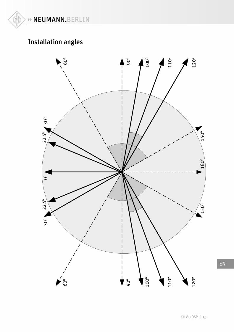
X Print out the diagram “Installation angles” that can be found at the end of this operating manual .
X Place the diagram at the listening position or center of the listening area .
X Using a tape measure, place the loudspeakers at the same distance from the center of the diagram “Installation angles” . To ensure good imaging, do this at an accuracy of at least 1 cm (1/2") .
X If the loudspeakers cannot be placed at the same distance from the listening position, com-pensate for distance differences > 1 cm (1/2") by delaying closer loudspeakers by 30 µs/cm (76 µs/inch) . Delay can be set directly in the loudspeaker using the Neumann .Control software .
X Check the location of the loudspeaker cabinet . This depends on the application:
• 2 .0 systems (stereo): ±30°, plus optional subwoofer(s)
• 5 .1 systems: ITU-R BS .775-1: 0°, ±30°, ±110° (±10°), plus optional subwoofer(s) (center, front left/right, surround left/right) ANSI/SMPTE 202M: 0°, ±22 .5°, arrays to the surround left and to the surround right, plus optional subwoofer(s)
• 7 .1 systems: 0°, ±30°, ±90°, ±150°, plus optional subwoofer(s) (center, front left/right, side left/right, back left/right)
• 3D systems See the recommendations from Dolby, DTS, Auro3D and ITU-R BS .2051-0 for loudspeaker positioning .
The acoustical axis of the KH 80 DSP is located at the midpoint of the bass and tweeter drivers . X Always point the acoustical axis, in the horizontal and vertical planes, towards the listening position .
The acoustical axis is a line perpendicular to the loudspeaker’s front panel along which the microphone was placed when tuning the loudspeaker’s crossover during design . Pointing the acoustical axis, in the horizontal and vertical planes, towards the listening position or center of the monitoring area will give the best measured and perceived sound quality .
X Position the loudspeaker so that there is a direct line of sight from the listening position to the bass and tweeter drivers .
Distances
dwall
Arranging the loudspeakers
at an angle
x = 7.7 cmy = 12.9 cm
EN
KH 80 DSP | 7
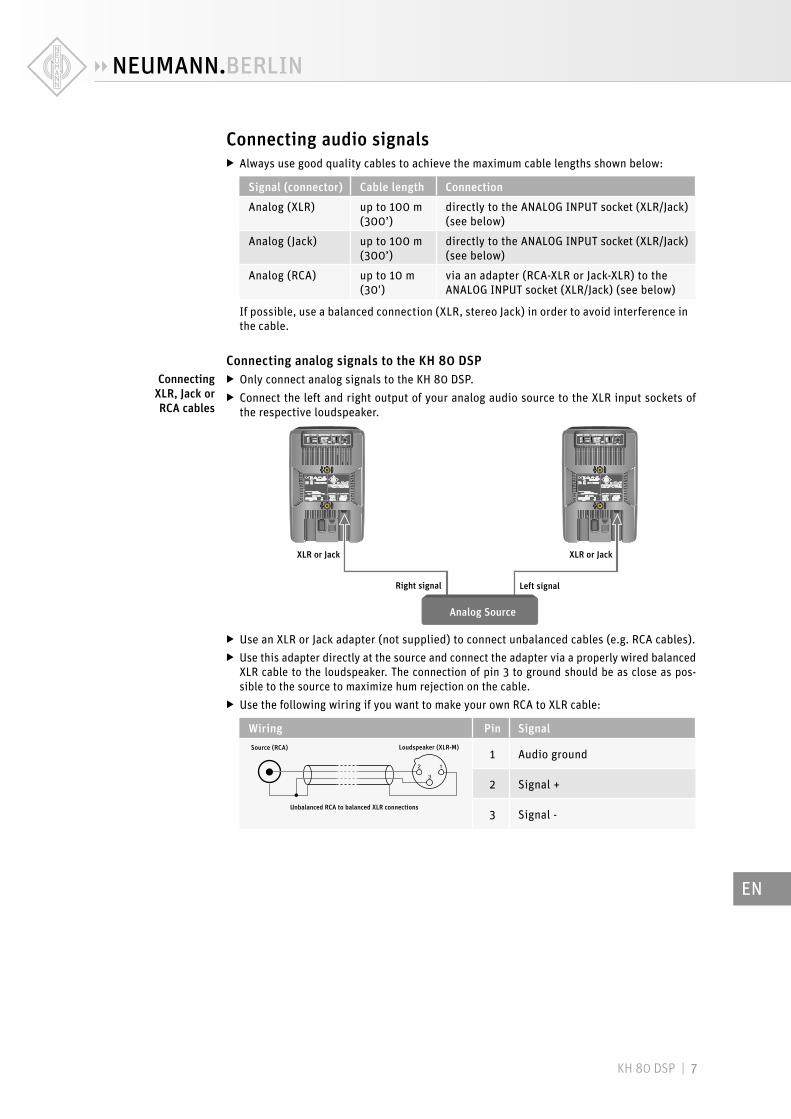
Connecting audio signals X Always use good quality cables to achieve the maximum cable lengths shown below:
Signal (connector) Cable length Connection
Analog (XLR) up to 100 m (300’)
directly to the ANALOG INPUT socket (XLR/Jack) (see below)
Analog (Jack) up to 100 m (300’)
directly to the ANALOG INPUT socket (XLR/Jack) (see below)
Analog (RCA) up to 10 m (30')
via an adapter (RCA-XLR or Jack-XLR) to the ANALOG INPUT socket (XLR/Jack) (see below)
If possible, use a balanced connection (XLR, stereo Jack) in order to avoid interference in the cable .
Connecting analog signals to the KH 80 DSP X Only connect analog signals to the KH 80 DSP . X Connect the left and right output of your analog audio source to the XLR input sockets of the respective loudspeaker .
XLR or Jack XLR or Jack
Left signalRight signal
Analog Source
X Use an XLR or Jack adapter (not supplied) to connect unbalanced cables (e .g . RCA cables) . X Use this adapter directly at the source and connect the adapter via a properly wired balanced XLR cable to the loudspeaker . The connection of pin 3 to ground should be as close as pos-sible to the source to maximize hum rejection on the cable .
X Use the following wiring if you want to make your own RCA to XLR cable:
Wiring Pin SignalSource (RCA)
Unbalanced RCA to balanced XLR connections
Loudspeaker (XLR-M)1 Audio ground
2 Signal +
3 Signal -
Connecting XLR, Jack or RCA cables
EN
KH 80 DSP | 8
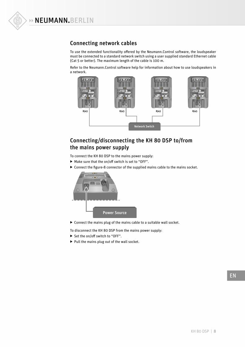
Connecting network cablesTo use the extended functionality offered by the Neumann .Control software, the loudspeaker must be connected to a standard network switch using a user supplied standard Ethernet cable (Cat 5 or better) . The maximum length of the cable is 100 m .
Refer to the Neumann .Control software help for information about how to use loudspeakers in a network .
RJ45 RJ45 RJ45RJ45
Network Switch
Connecting/disconnecting the KH 80 DSP to/from the mains power supplyTo connect the KH 80 DSP to the mains power supply:
X Make sure that the on/off switch is set to “OFF” . X Connect the figure-8 connector of the supplied mains cable to the mains socket .
Power Source
X Connect the mains plug of the mains cable to a suitable wall socket .
To disconnect the KH 80 DSP from the mains power supply: X Set the on/off switch to “OFF” . X Pull the mains plug out of the wall socket .
EN
KH 80 DSP | 9
Configuring and using the KH 80 DSP
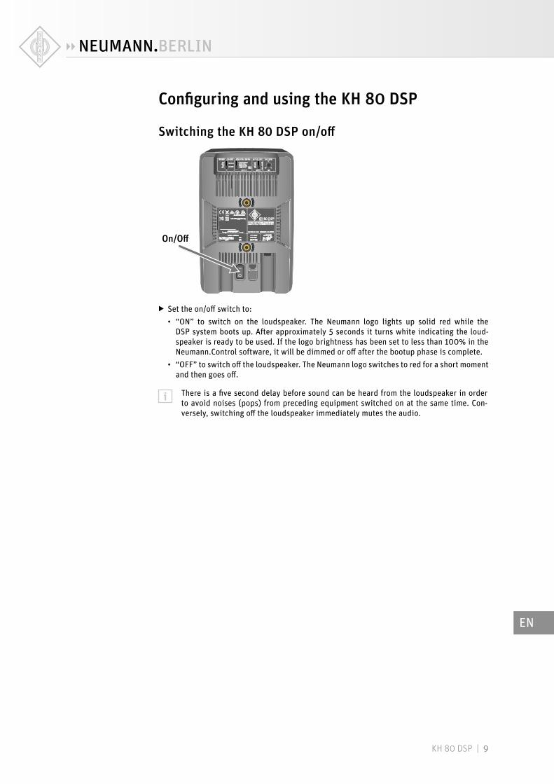
Switching the KH 80 DSP on/off
On/Off
X Set the on/off switch to:
• “ON” to switch on the loudspeaker . The Neumann logo lights up solid red while the DSP system boots up . After approximately 5 seconds it turns white indicating the loud-speaker is ready to be used . If the logo brightness has been set to less than 100% in the Neumann .Control software, it will be dimmed or off after the bootup phase is complete .
• “OFF” to switch off the loudspeaker . The Neumann logo switches to red for a short moment and then goes off .
There is a five second delay before sound can be heard from the loudspeaker in order to avoid noises (pops) from preceding equipment switched on at the same time . Con-versely, switching off the loudspeaker immediately mutes the audio .
EN

KH 80 DSP | 10
Functionality of the Neumann logo
Action Logo indication
Firmware activities
Loudspeaker is booting up Solid red
Loudspeaker boot up error Fast red flashing
Loudspeaker firmware is being updated Solid rosé
Loudspeaker resetting to factory default settings Rosé flutter flash
Everyday operation
Operating normally (dimmable via Neumann .Control)
Solid white
Loudspeaker in active system is solo’ed in Neumann .Control
Solid white
Loudspeaker system output level is dimmed or muted (GUI button on Operate page)
Solid rosé
Neumann .Control is saving changes to the loudspeaker’s memory (not Operate page commands)
Solid rosé
Protection and Standby
Protection system is activated (takes priority over other indications)
Red
Neumann.Control Alignment
Setup: Identify the loudspeaker Rosé pulses (2 Hz) + audible ID tone
Guided Alignment: Loudspeaker is selected Rosé pulses (0 .5 Hz)
Manual Alignment: Loudspeaker is selected Solid rosé
Precision Alignment: During countdown 10 rosé pulses (1 Hz)
Precision Alignment: Measuring the loudspeaker Red to White crossfade + test signal
Precision Alignment: Loudspeaker not being measured
White
EN
KH 80 DSP | 11
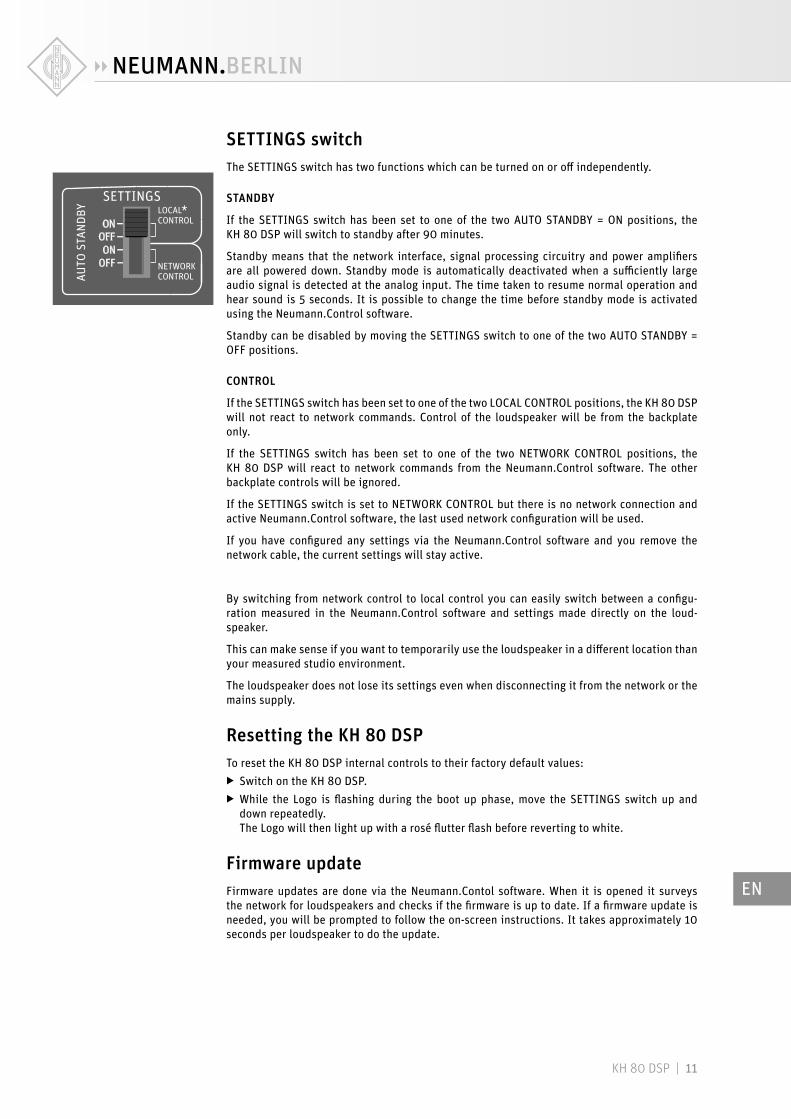
SETTINGS switchThe SETTINGS switch has two functions which can be turned on or off independently .
STANDBY
If the SETTINGS switch has been set to one of the two AUTO STANDBY = ON positions, the KH 80 DSP will switch to standby after 90 minutes .
Standby means that the network interface, signal processing circuitry and power amplifiers are all powered down . Standby mode is automatically deactivated when a sufficiently large audio signal is detected at the analog input . The time taken to resume normal operation and hear sound is 5 seconds . It is possible to change the time before standby mode is activated using the Neumann .Control software .
Standby can be disabled by moving the SETTINGS switch to one of the two AUTO STANDBY = OFF positions .
CONTROL
If the SETTINGS switch has been set to one of the two LOCAL CONTROL positions, the KH 80 DSP will not react to network commands . Control of the loudspeaker will be from the backplate only .
If the SETTINGS switch has been set to one of the two NETWORK CONTROL positions, the KH 80 DSP will react to network commands from the Neumann .Control software . The other backplate controls will be ignored .
If the SETTINGS switch is set to NETWORK CONTROL but there is no network connection and active Neumann .Control software, the last used network configuration will be used .
If you have configured any settings via the Neumann .Control software and you remove the network cable, the current settings will stay active .
By switching from network control to local control you can easily switch between a configu-ration measured in the Neumann .Control software and settings made directly on the loud-speaker .
This can make sense if you want to temporarily use the loudspeaker in a different location than your measured studio environment .
The loudspeaker does not lose its settings even when disconnecting it from the network or the mains supply .
Resetting the KH 80 DSPTo reset the KH 80 DSP internal controls to their factory default values:
X Switch on the KH 80 DSP . X While the Logo is flashing during the boot up phase, move the SETTINGS switch up and down repeatedly .The Logo will then light up with a rosé flutter flash before reverting to white .
Firmware updateFirmware updates are done via the Neumann .Contol software . When it is opened it surveys the network for loudspeakers and checks if the firmware is up to date . If a firmware update is needed, you will be prompted to follow the on-screen instructions . It takes approximately 10 seconds per loudspeaker to do the update .
EN
KH 80 DSP | 12
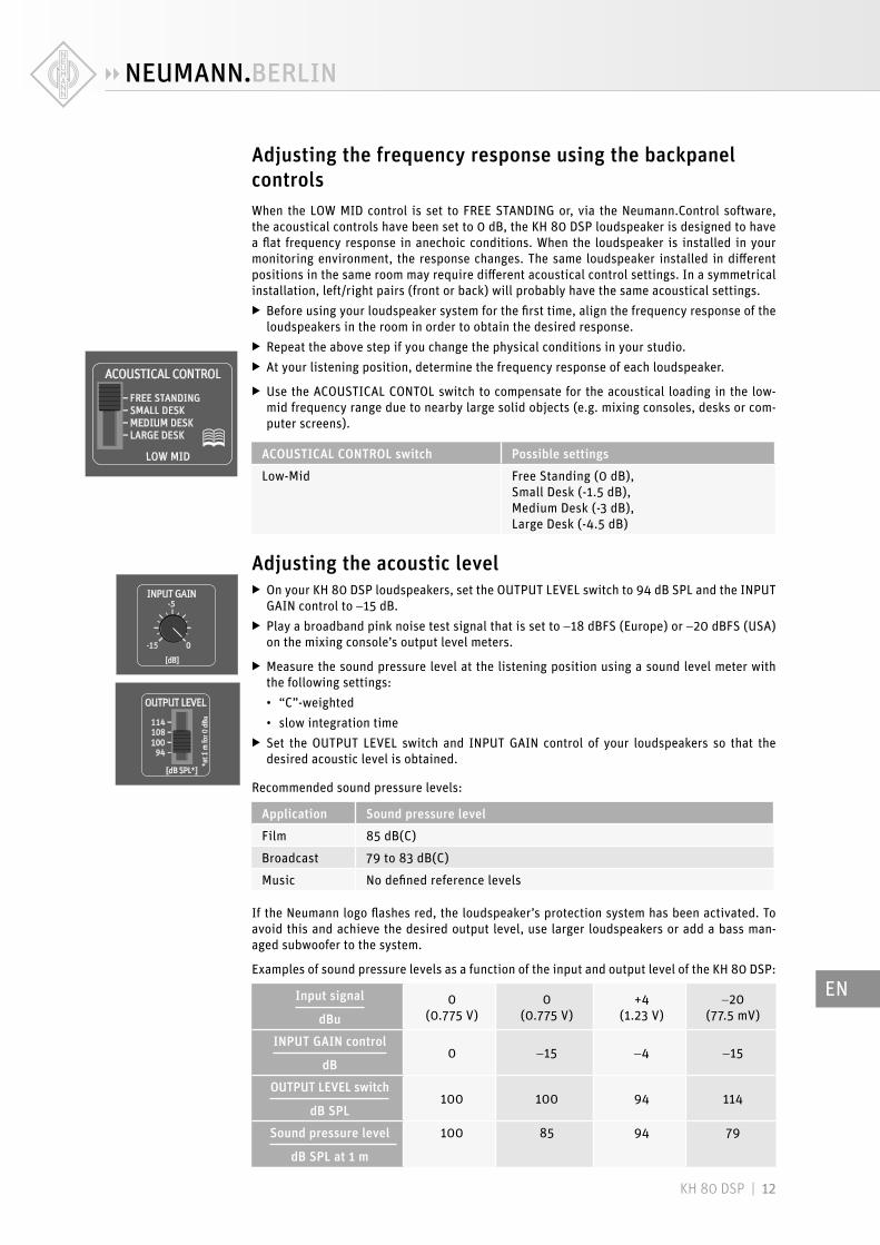
Adjusting the frequency response using the backpanel controlsWhen the LOW MID control is set to FREE STANDING or, via the Neumann .Control software, the acoustical controls have been set to 0 dB, the KH 80 DSP loudspeaker is designed to have a flat frequency response in anechoic conditions . When the loudspeaker is installed in your monitoring environment, the response changes . The same loudspeaker installed in different positions in the same room may require different acoustical control settings . In a symmetrical installation, left/right pairs (front or back) will probably have the same acoustical settings .
X Before using your loudspeaker system for the first time, align the frequency response of the loudspeakers in the room in order to obtain the desired response .
X Repeat the above step if you change the physical conditions in your studio . X At your listening position, determine the frequency response of each loudspeaker .
X Use the ACOUSTICAL CONTOL switch to compensate for the acoustical loading in the low-mid frequency range due to nearby large solid objects (e .g . mixing consoles, desks or com-puter screens) .
ACOUSTICAL CONTROL switch Possible settings
Low-Mid Free Standing (0 dB), Small Desk (-1 .5 dB), Medium Desk (-3 dB), Large Desk (-4 .5 dB)
Adjusting the acoustic level X On your KH 80 DSP loudspeakers, set the OUTPUT LEVEL switch to 94 dB SPL and the INPUT GAIN control to -15 dB .
X Play a broadband pink noise test signal that is set to -18 dBFS (Europe) or -20 dBFS (USA) on the mixing console’s output level meters .
X Measure the sound pressure level at the listening position using a sound level meter with the following settings:
• “C”-weighted
• slow integration time X Set the OUTPUT LEVEL switch and INPUT GAIN control of your loudspeakers so that the desired acoustic level is obtained .
Recommended sound pressure levels:
Application Sound pressure level
Film 85 dB(C)
Broadcast 79 to 83 dB(C)
Music No defined reference levels
If the Neumann logo flashes red, the loudspeaker’s protection system has been activated . To avoid this and achieve the desired output level, use larger loudspeakers or add a bass man-aged subwoofer to the system .
Examples of sound pressure levels as a function of the input and output level of the KH 80 DSP:
Input signal
dBu0
(0 .775 V)0
(0 .775 V)+4
(1 .23 V)-20
(77 .5 mV)
INPUT GAIN control
dB0 -15 -4 -15
OUTPUT LEVEL switch
dB SPL100 100 94 114
Sound pressure level
dB SPL at 1 m
100 85 94 79
EN

KH 80 DSP | 13
Cleaning and maintaining the KH 80 DSPCAUTIONDamage to the product caused by liquids!
Liquids entering the product can cause a short-circuit in the electronics and damage or even destroy the product . X Keep all liquids away from the product!
X Before cleaning, disconnect the product from the mains power supply . X Use a soft, dry, and lint-free cloth to clean the product .
TroubleshootingProblem Cause SolutionThe Neumann logo is off, no sound is heard from the KH 80 DSP
The KH 80 DSP main fuse has blown .
Have the product checked by an authorized Neumann service partner .
The Neumann logo is off or not clearly visible, but sound is heard from the KH 80 DSP
The Neumann logo is switched off or dimmed .
Switch on the Neumann logo and switch off the dimming (see page 9) .
The KH 80 DSP is humming Incorrect wiring in the audio cable and/or poor quality grounding in the audio cable .
Check the cabling, especially if unbalanced cabling has been used - see the cable wiring digram on page 7 . Use gold plated connectors . Set the output level of the KH 80 DSP as low as possible and set the output level of the audio source as high as possible, without causing it to clip .
The loudspeaker sounds very “thin” in the bass . The low frequency response is very low .
Incorrect wiring in the audio cable or adapter .
Check the cabling, especially if unbalanced cabling has been used - see the cable wiring digram on page 7 .
For further information, please refer to the “Questions & Answers” section on the product page at www .neumann .com .
SpecificationsFor a complete list of the product spefications please refer to the product page of the KH 80 DSP at www .neumann .com .
Product properties
Power supply 100 to 240 V~, 50/60 Hz
Power consumption (230 V / 100 V) Standby Idle Full output
<330 mW / <50 mW 9 W / 8 W 180 W
Dimensions (H x W x D) 233 x 154 x 194 mm (9 1/8" x 6" x 7 5/8")
Weight 3 .4 kg (7 lbs 8 oz)
Temperature
Operation and storage, unpacked +10 °C to +40 °C (+50 °F to +104 °F)
Transport and storage, packed in original packaging –25 °C to +60 °C (–13 °F to +140 °F)
Relative humidity
Operation and storage, unpacked max . 75 % (non-condensing)
Transport and storage, packed in original packaging max . 90 % (non-condensing)
EN

KH 80 DSP | 14
In compliance with
Europe EMC EN 55032, EN 55103-2, Electromagnetic Environment: Class E3 Safety EN 60065, EN 62368-1 RoHS EN 50581
USA 47 CFR 15 subpart B
Canada CAN ICES-3 (B)/NMB-3(B)
Acoustical measurements and block diagramAdditional technical data such as acoustical measurements and a block diagram can be found on the product page of the KH 80 DSP at www .neumann .com .
AccessoriesProduct Description
LH 28 Tripod stand adapter
LH 29 TV spigot (lighting stand adapter)
LH 32 Wall L-bracket
LH 37 Subwoofer adapter
LH 43 Surface mounting plate
LH 45 Wall bracket
LH 46 Adjustable ceiling drop adapter
LH 47 Mounting adapter plate
LH 48 Tripod adapter plate
LH 61 Adjustable L-bracket
LH 64 Omnimount/VESA adapter
LH 65 Table stand
PAK 1 Precision alignment kit
EN
KH 80 DSP | 15
Installation angles
00°°
111100°°
118800°°
9900°°
115500°°
3300°°
22.5
°22
.5°
6600°°
112200°°
110000°°
111100°°9900
°°
115500°°
3300°°
6600°°
112200°°
110000°°
EN