keysight technologies gps receiver testing
TRANSCRIPT

Navigation message
25 pages/frames
37500 bits
12.5 minutes
Frame (page)
1500 bits
30 seconds
Sub-frame 1
8 bits
pre
am
ble
pari
ty
reserved
16 bits 6 bits 7 bits
ID
pari
tyTime of week
TOW
16 bits 6 bits
Satellite clock and health data
Ephemeris Ephemeris AlmanacPartial almanac & other data
Sub-frame 3 Sub-frame 4 Sub-frame 5
Sub-frame 2
300 bits
6 seconds
Telemetry word (TLM)
30 bits 0.6 seconds
Handover word (HOW)
30 bits 0.6 seconds
Keysight TechnologiesGPS Receiver Testing
Application Note

2
Table of Contents
Introduction ................................................................................................ 3
Navigation signals ............................................................................. 3
GPS technology .................................................................................. 4
Assisted GPS (A-GPS) ....................................................................... 4
GPS Test Requirements .................................................................... 4
GPS receiver basics ........................................................................... 4
GPS antennas ..................................................................................... 5
GPS receiver verification .................................................................. 5
GPS Satellite Simulation .......................................................................... 6
Types of GPS Tests .................................................................................. 7
Time To First Fix (TTFF) .................................................................... 7
Connecting GPS receivers to a GPS signal generator ................. 9
Receivers with no external connections .............................. 9
Receivers with external connections .................................... 9
Typical GPS Receiver Tests .................................................................. 10
TTFF tests .......................................................................................... 11
Location accuracy (predictable, repeatable, relative)................ 12
Reacquisition time ........................................................................... 12
Sensitivity .......................................................................................... 12
Interference testing ......................................................................... 13
Multipath testing.............................................................................. 13
Other errors ....................................................................................... 13
Antenna testing ................................................................................ 13
GPS Receiver Tests using the N7609B Signal Studio
for Global Navigation Satellite Systems ............................................. 14
Setting up the tests ......................................................................... 15
Summary ................................................................................................... 17
Bibliography ............................................................................................. 17
Reference Literature ............................................................................... 17

3
Introduction
As GPS technology becomes more
common, GPS receiver manufactur-
ers, OEM integrators, and contract
manufacturers struggle to determine
the appropriate standard tests to
verify GPS receiver performance.
Verification procedures require a
controlled environment that facilitates
precise repeatability. In most cases,
using actual GPS satellite signals
received through an antenna does
not provide such an environment.
This paper describes the typical GPS
receiver tests used today for GPS
receiver verification. It also introduces
a real-time GPS signal simulation
application and platform capable of
generating the required GPS signals
for a repeatable and flexible test
environment.
GPS (Global Positioning System) is a
satellite-based technology. It allows
users to determine positions at points
in time by utilizing navigational sig-
nals broadcast by multiple satellites,
known as a satellite constellation.
Currently, this constellation consists
of 24 active satellites, which orbit the
earth at an altitude of approximately
11,500 miles. Each satellite completes
an orbit every 12 hours. The constel-
lation includes some in-orbit spare
satellites which can be activated to
replace any satellites which may fail.
The GPS system (also called
NAVSTAR) was developed by the
United States and is owned and oper-
ated by the United States Department
of Defense. The initial satellites were
launched in 1978, and by 1994 a full
constellation of 24 satellites was
available. Satellites typically last 8
to 12 years and new satellites are
periodically launched to replace older
satellites. Enhancements have been
made over the years and currently
there are a number of new technolo-
gies, including new signals, that are
being planned.
Navigation signals
In the current GPS satellite constel-
lation, each satellite broadcasts two
different navigation signals, known as
L1 and L2. The L1 signal is broadcast
on a frequency of 1575.42 MHz, and
the L2 signal is broadcast on a fre-
quency of 1227.60 MHz. The L2 signal
is encrypted and is available only to
authorized users – typically military
applications. The L2 signal provides
a highly reliable and accurate time
and location solution. The L1 signal
is not encrypted and is available to
users worldwide, 24 hours a day,
without charge or subscription. GPS
navigation signals are broadcast with
circular polarization. See Figure 1.
For a given signal (L1 or L2), all
satellites broadcast on the same
frequency. The signals are differenti-
ated by the different codes that are
transmitted by each satellite. This is
called “code domain multiple access”
or CDMA.
Two different code rates are
used. The first code is the Coarse
Acquisition code, or C/A code, which
has a code rate of 1.023 MHz and
it repeats every 1 millisecond. The
second code rate is 10.23 MHz, it
is called the Precise, or P code and
it repeats every week. Typically the
P code is encrypted to form a code
called P(Y). Each satellite is assigned
a unique code sequence for the C/A
and P codes, respectively. These
sequences are identified by a number
called the PRN (pseudo-random) ID.
The navigation signals convey infor-
mation to the GPS receivers including
precise timing information as well
as system status, orbit descriptions
of each satellite, and satellite health
information. Using this information a
receiver can determine the distance
to each satellite and, using a triangu-
lation approach, a position and time
can be determined.
Navigation signals are broadcast with
a fairly low power and appear at a
minimum level of about -155 dBm at
sea level. Signal levels may be even
lower inside of buildings or under
tree cover. These signal levels are
extremely low and require significant
amplification and baseband process-
ing to recover.
L1 Signal
L2 Signal
modulo 2 adder
90°
L1 Carrier 1.57542 GHz
L2 Carrier 1.2276 GHz
C/A Code 1.023 MHz
Navigation Data 50 Hz
P Code 10.23 MHzmodulator
Figure 1. GPS signal structure.

4
GPS technology
Although GPS receivers have been
available for many years, initial imple-
mentations were large, expensive,
and consumed considerable power.
Because of this, the GPS application
was limited to high-end commercial
and military applications.
In recent years, the cost for GPS
receivers has declined significantly
for commercial technology. The result
is that GPS receiver technology
has recently become increasingly
important in consumer products such
as handheld receivers, automotive
receivers, mobile phones, and other
tracking devices.
Assisted GPS (A-GPS)
A-GPS development was driven by a
U.S. FCC E911 requirement to quickly
provide a cell phone location to
emergency call dispatchers. A-GPS
greatly reduces Time To First Fix
(TTFF) measurements and allows GPS
receivers to identify satellites at much
lower power levels.
"Assistance data" is provided by the
base station to help the mobile phone
identify the satellites that are visible.
The mobile phone can then quickly
find these satellites and calculate it's
position. Typical TTFF can be reduced
from 60 seconds to under 10 seconds.
There are two methodologies for
sending and receiving assistance
data. They are control plane and IP
data channels (user plane).
GPS Test Requirements
The GPS user experience for com-
mercial applications is affected by
several factors. GPS devices which
provide an enhanced user experience
will sell better, so manufacturers are
looking for factors to differentiate
their receivers. Typical factors which
determine the outcome of the user
experience include the following
factors:
1) When a GPS device is turned on,
how long is it until the position of
the receiver is determined?
2) When a weak or poor signal area
is encountered, can the receiver
still determine its position?
3) If the signal is interrupted and
then restored, how long does it
take for the receiver to recover
and resume calculating its position?
4) Accuracy of the calculated location.
There are of course other factors
such as cost, user interface, turn-by-
turn navigation, spoken directions,
and so forth that are important to
users, but these are not so dependent
on the GPS receiver performance.
For commercial or military applica-
tions, there may be many other kinds
of GPS conditions that are important,
such as:
1) How accurately can a position or
time be determined?
2) How repeatable is the solution?
3) How sensitive is the receiver to
interference or jamming?
4) How rapidly can the receiver
report its position (if the receiver
is moving rapidly – such as in an
airplane)?
From this point forward, this applica-
tion note will focus mainly on testing
for consumer GPS applications.
GPS receiver basics
From a high level perspective, the
GPS unit appears as an antenna
which senses the navigation signals,
and has an output of some kind
which reports status, positions, and
time (via some I/O port or a screen).
A typical block diagram for GPS
receivers includes an antenna, an
RF front end/down converter, a
baseband processing element, and a
computation engine. In some cases
these elements may be integrated in
a single module which can be quite
small – on the order of 1 square cm.
See Figure 2.
Figure 2. GPS receiver block diagram.
LNA
Active
antenna
RF front
end and
down
converter
Baseband
processing,
correlators,
tracking
Calculation
engine,
error
estimation,
correction
GPS
receiver I/O port,
display,
buttons

5
GPS antennas
As previously noted, navigation
signals on the earth’s surface are
quite low in power. In order to recover
the navigation signal successfully,
active antennas are typically utilized
with gains of 20 or 30 dB. For these
active antennas, a DC voltage is
supplied from the receiver over the
same cable that transmits the signal
to the receiver. In most commercial
implementations the antennas are
integrated into the receiver unit. In
some cases a port for an external
antenna may be provided.
GPS receiver veriication
In order to test a GPS receiver, we
can use an antenna and try to receive
off-the-air signals. However realistic
this approach may be, it can only pro-
vide limited information because the
signals presented to the receiver are
highly variable and non-repeatable.
In addition, testing under specific
conditions such as remote locations
or high velocities becomes expensive
and impractical.
To address this issue, a GPS signal
simulator may be used. These devices
produce an output signal that models
the signal that would be received by
the GPS receiver – a mix of signals
from many different satellites at
different time delays, Doppler shifts,
and power levels. If the proper signal
is presented to the receiver, it can
perform signal acquisition and track-
ing and provide a navigation solution
(location fix).
Signals can be created by model-
ing the motions of satellites at a
particular point in time. By knowing
a specific receiver location (latitude,
longitude, altitude), the proper-
ties of the navigation signal as it
propagates to the receiver location
can be modeled and reproduced by
a signal generator. These properties
can include path losses, distortions
due to atmospheric effects, as well
as relativistic effects and the effects
of transit time as the signal travels
from the satellite transmitter to the
receiver antenna.
Using a signal simulator with appro-
priate models, a repeatable, known
signal can be presented to the GPS
receiver to allow testing to determine
the receiver’s ability to operate under
various conditions, locations, times,
and movements.

6
GPS Satellite Simulation
The N5106A PXB baseband genera-
tor and channel emulator and the
N5182A MXG RF vector signal
generator combined with the N7609B
Signal Studio for Global Navigation
Satellite Systems (GNSS) is a solution
capable of generating the GPS signals
required for comprehensive GPS
receiver testing. The N5106A PXB
and N5182A MXG combination is a
high performance, general purpose
signal generator that can not only
create the required GPS signals, but
also signals for other wireless stan-
dards such as Bluetooth®, WLAN,
LTE, and WiMAX™. The N7609B is a
software application with the ability
to create and generate custom GPS
signals for reliable, repeatable, and
flexible GPS receiver testing.
Features of the N7609B include:
– 15 satellite simulation (depends on
scenario and satellite visibility)
– 24 channels total (satellites +
multipath)
– Individual real-time channel power
adjustments
– Individual real-time channel on/off
– Scenario generation capability
(Option RFP required)
– Moving GPS receiver simulation
– Up to 8 hour scenario playback
with 8 channels
– Multipath signal capability
– Ability to select scenario start time
– Static test mode
- Individual channel Doppler shift
adjustments
- Individual channel delay adjust-
ments
- Individual power control adjust-
ments for each channel
– Scenario generation and editing
- A-GPS assistance data for each
scenario
- Scenario generation for static
and moving GPS receivers
- Ionospheric and tropospheric
modeling
- NMEA data input for scenario
generation
- Scenario editor to apply power,
delay, and Doppler offset for
multipath channels
- Elevation mask for satellite
visibility
N5106A PXB platform capabilities
– Remote capability (control PXB and
N7609B from an external PC)
– Summing of baseband signals
for interference testing (requires
additional baseband generator for
PXB)
– Marker output
– AWGN support (requires Option
N5106A-JFP Calibrated AWGN on
the PXB)
– Digital IQ output (N5102A digital –
signal interface module required)
– Analog IQ output
Figure 3. N5106A PXB and N5182A MXG RF signal generator.

7
Types of GPS Tests
Classical receiver testing for digital
systems normally involves testing
bit error rate (BER, FER, PER, BLER)
with of specific power, noise, fading,
and interference conditions. With
GPS we are not only concerned with
the recovery of the digital content of
the signal, but the receiver must also
track the arrival time of the signal
very closely (synchronization).
Correct tracking of arrival times
requires tracking the timing of the
signal very carefully. In most GPS
receivers this is tracked in terms of
carrier phase, literally the number
of carrier wavelengths and fractions
of carrier wavelengths between the
receiver and the transmitter. At L1
frequency, this is a resolution of C
(the speed of light) divided by the
carrier frequency F0 = 1575420000 Hz.
This gives a resolution of fractions of
nano-seconds.
Tracking is complicated by the
relativistic effects of the velocity
between the receiver and each of
the satellites. This situation causes a
phenomenon known as Doppler shift
which means that the receiver per-
ceives the frequency of the signal to
be shifted by some amount depending
on the relative velocity. So, a receiver
has to track not only the timing of the
signal from each satellite, but also
the Doppler shift of each signal. For
receivers that are not moving, the
Doppler shift can be on the order of
±5000 Hz.
Further, the data rate for GPS signals
is only 50 bits per second, so test-
ing for a bit error rate of 1 error in
1,000,000 bits at 95% confidence
would mean running a test that would
take hundreds of hours. Clearly we
must do something different.
In addition, it turns out that for the
GPS receiver, the recovery of data
bits is only necessary for short time
periods – as little as 18 seconds every
few hours. During the remaining time,
the receiver just has to track the car-
rier phase.
This means that there are really
two sensitivity levels – one for data
recovery, and one for tracking.
Time To First Fix (TTFF)
When a receiver is turned on, it must
do some searching to find the satel-
lite signals – this process is called
acquisition. It must then track the
signals, and compute a position. The
time from turn on to the availability
of the first valid location fix is called
Time To First Fix or TTFF. TTFF is a
critical parameter for testing GPS
receivers. It relates directly back to
a user desire which is to have a loca-
tion fix as soon as possible.
When testing GPS receivers, you’ll
often hear the terms Hot Start, Cold
Start, and Warm Start. These terms
refer to the data that is available
to the receiver when it is turned
on. Most GPS receivers have some
persistent memory which stores the
time of day and predictions of satel-
lite orbits. When you turn on these
receivers, they will use this data as a
“hint” to make it easier to search for
active satellite signals.

8
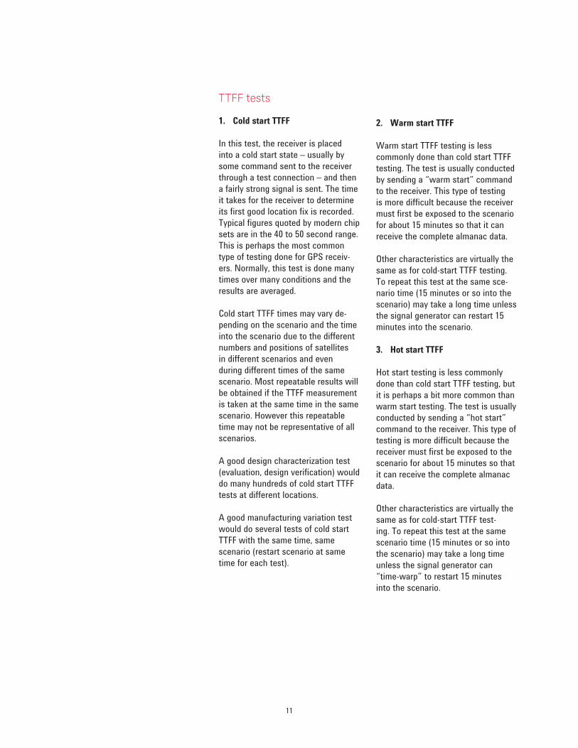
Figure 4. Satellite navigation message.
Hot start
If the receiver has been off for a short
time (less than an hour or two) and
has not moved much (100 meters
or less) it will have fairly accurate
information on satellites and can typi-
cally use this information to acquire
satellite signals and compute a posi-
tion relatively rapidly. This scenario
is termed a hot start and may be the
case that results from a short power
interruption or a battery change.
Warm start
If the receiver has been off for a
longer time, or moved farther while
it was powered off, it will experience
a warm start. With a warm start, the
receiver has sufficient data to know
what time it is (approximately) but
it doesn’t really know where it is.
One necessary condition for a warm
start is that the receiver has what is
known as “Almanac Data.”
Almanac data is a long-term predic-
tion of satellite orbits and is usually
pretty accurate for a 24-hour day
and deteriorates over the course of
several days. Typically, after 7 days
the accuracy becomes very poor.
Almanac data is transmitted by each
satellite. It takes about 15 minutes
of good signals from at least one
satellite in order to receive all the
almanac data. This data will be good
for several days. See Figure 4 for a
description of the satellite navigation
message.
For a warm start condition, the
receiver has to work harder to acquire
the signal, and this means that the
TTFF becomes longer.
Navigation message
25 pages/frames
37500 bits
12.5 minutes
Frame (page)
1500 bits
30 seconds
Sub-frame 1
8 bits
pre
am
ble
pari
ty
reserved
16 bits 6 bits 7 bits
ID
pari
tyTime of week
TOW
16 bits 6 bits
Satellite clock and health data
Ephemeris Ephemeris AlmanacPartial almanac & other data
Sub-frame 3 Sub-frame 4 Sub-frame 5
Sub-frame 2
300 bits
6 seconds
Telemetry word (TLM)
30 bits 0.6 seconds
Handover word (HOW)
30 bits 0.6 seconds

9
Cold start
GPS receivers that are started up with
no data as to what time it is or where
the satellites are located are said to
be in cold start mode. In this mode,
the receiver’s first job is to acquire
satellite signals. In order to do this,
it must search each of the available
CDMA codes, as well as the fre-
quency space over a range of ±5000
Hz of Doppler shift. This is a fairly
difficult task which requires signals
of relatively strong amplitude and
may take quite a long time. In older
receivers it may take several minutes.
In newer receivers, the timeframe
has been reduced so that it is on the
order of 10 to 20 seconds.
With a cold start, the receiver must
receive at least 18 seconds of good
data from each satellite in order to
receive an accurate description of the
satellite’s orbit (known as ephemeris
data). Once done, the receiver will
have sufficient information to com-
pute its first location fix. TTFF for cold
start conditions are typically longer
than either hot start or warm start
conditions. Modern receivers can
achieve the TTFF in less than a min-
ute. Cold start TTFF is an important
parameter for GPS receivers and is
typically one of the first parameters to
test in a GPS receiver.
Connecting GPS receivers to a GPS signal generator
Presenting signals to a GPS receiver
can present several challenges. The
factors involved are:
1) Receiver may not have an
external antenna connection
2) RF power to the receiver is
very low
3) Power to the receiver must be
known accurately to make good
measurements
4) Receivers tend to have active
antenna connections
5) Some receivers automatically
switch between internal and
external connections
Receivers with no external connections
For receivers with no external con-
nections, a radiated signal must be
presented. This is called radiated
testing or over-the-air (OTA) testing.
It involves connecting the signal
generator to some kind of antenna
that radiates the signal to the receiver
antenna. Since these radiated signals
may interfere with the real GPS
signals, this radiated testing should
only be done inside an RF chamber to
prevent interference.
This scenario presents some
additional problems:
1) Calibration of power to the
antenna can be difficult
2) The external antenna expects a
circularly polarized signal – it’s
best to use helical or stacked
dipole antennas to generate
circularly polarized signals
3) The distance between the trans-
mitter and the receiver should be
at least several wavelengths
to avoid “near field” couplings
Receivers with external con-nections
Receivers with external connections
present somewhat fewer problems.
They require what is called “conduc-
tive” testing, which involves no radia-
tion of signals over the air. See Figure
5. The signal generator usually cannot
be directly connected to the receiver
due to several problems:
1) Most GPS receivers expect
ACTIVE antennas – this means
they supply a DC voltage
to the antenna connector. The DC
voltage may damage the signal
generator, so it must be blocked.
In-line DC blocking devices are
commercially available.
2) In addition, some receivers
“sense” current draw on the DC
supply. If there is no current
drawn, they may assume that no
antenna is connected. In such
cases, the current draw must be
simulated by some resistive
load and perhaps a series
inductor between the signal line
and the ground. Such a device
may need to be custom built,
depending on receiver
requirements.
3) Signal generators typically
cannot generate the low level
signals required directly. In some
cases, a signal level as low
as -155 dBm could be required,
which means that an external
attenuation device will likely be
needed.
Receiver connection to signal
generator – General
In both radiated and conductive
testing, the power delivered to the
receiver must be carefully calibrated
if meaningful, repeatable results are
to be obtained. For a typical signal
with 8 active satellites, the net power
delivered to the receiver will need to
be between -125 and -150 dBm.

10
Figure 5. Typical GPS receiver test setup.
Typical GPS Receiver Tests
The following are representative of
the tests performed on GPS receivers.
Most receivers will not be subjected
to all of these tests, or perhaps will
be subjected to them only during
some design verification stage. Other
tests might be done at a manufactur-
ing level to determine if the receiver
is responding according to desired or
specified parameters.
Perhaps the most common tests are
cold start TTFF and location accuracy.
Other tests becoming more popular
include sensitivity and multipath
testing, which are built on top of TTFF
and location accuracy.
One general note for all of these
tests is that they are sensitive to the
exact positions and movements of
satellites. This means that the results
are going to be variable unless the
tests are repeated with exactly the
same time in the same scenario.
Furthermore, such a “repeatable”
number may not be representative
of the receiver’s performance in
general. Typical measurements must
be performed under different start
times, dates, and locations. These
measurements are then averaged to
provide a meaningful value.
50 dB attenuator
DC block
USB connection to PC
RF out
GPS
receiver
11
TTFF tests
1. Cold start TTFF
In this test, the receiver is placed
into a cold start state – usually by
some command sent to the receiver
through a test connection – and then
a fairly strong signal is sent. The time
it takes for the receiver to determine
its first good location fix is recorded.
Typical figures quoted by modern chip
sets are in the 40 to 50 second range.
This is perhaps the most common
type of testing done for GPS receiv-
ers. Normally, this test is done many
times over many conditions and the
results are averaged.
Cold start TTFF times may vary de-
pending on the scenario and the time
into the scenario due to the different
numbers and positions of satellites
in different scenarios and even
during different times of the same
scenario. Most repeatable results will
be obtained if the TTFF measurement
is taken at the same time in the same
scenario. However this repeatable
time may not be representative of all
scenarios.
A good design characterization test
(evaluation, design verification) would
do many hundreds of cold start TTFF
tests at different locations.
A good manufacturing variation test
would do several tests of cold start
TTFF with the same time, same
scenario (restart scenario at same
time for each test).
2. Warm start TTFF
Warm start TTFF testing is less
commonly done than cold start TTFF
testing. The test is usually conducted
by sending a “warm start” command
to the receiver. This type of testing
is more difficult because the receiver
must first be exposed to the scenario
for about 15 minutes so that it can
receive the complete almanac data.
Other characteristics are virtually the
same as for cold-start TTFF testing.
To repeat this test at the same sce-
nario time (15 minutes or so into the
scenario) may take a long time unless
the signal generator can restart 15
minutes into the scenario.
3. Hot start TTFF
Hot start testing is less commonly
done than cold start TTFF testing, but
it is perhaps a bit more common than
warm start testing. The test is usually
conducted by sending a “hot start”
command to the receiver. This type of
testing is more difficult because the
receiver must first be exposed to the
scenario for about 15 minutes so that
it can receive the complete almanac
data.
Other characteristics are virtually the
same as for cold-start TTFF test-
ing. To repeat this test at the same
scenario time (15 minutes or so into
the scenario) may take a long time
unless the signal generator can
“time-warp” to restart 15 minutes
into the scenario.

12
Location accuracy (predictable, repeatable, relative)
Location accuracy refers to the
ability to achieve a location fix that
is as close as possible to the desired
position, both in repeatability and
accuracy. There are several variations
of location accuracy testing, as fol-
lows:
1. A Relative Location Accuracy test
refers to comparing the location
fixes obtained by cold/warm/
hot starting, while at the same
locating and comparing the
variation between fixes. A low
variation means that the receiver
can achieve a relatively accurate
location fix, which is good if you
want to return to the same
location, using the same receiver
– but don’t care too much about
how close the longitude/latitude/
altitude numbers are to the actual
location.
2. The Absolute Location Accuracy
test refers to the process of
comparing the location fixes
obtained by cold/warm/hot
starting, while at the same
locating and comparing the
variation between the location
fixes and the ideal location
provided by the scenario.
3. Moving or Dynamic Location
Accuracy tests – these refer to
a scenario that simulates
movement of the receiver while
conducting the accuracy tests
described above.
Reacquisition time
In this test we characterize the per-
formance of the receiver in a scenario
where the signal is greatly reduced or
interrupted for some short period of
time and is then restored. An example
of this would be a vehicle going
through a tunnel or under some heavy
tree cover. In this case the receiver
is briefly unable to track most or all
of the satellites, but must re-acquire
(track) the signal when “visibility” is
restored. This scenario can be simu-
lated by briefly reducing or turning off
the signal generator power and then
restoring it without restarting the
scenario.
A related test would involve inter-
rupting the signals from only a subset
of the satellites. An example of this
would be driving behind a building or
hill which temporarily blocks out the
signals from part of the sky.
The results from this test will usually
be compared with signals above the
minimal sensitivity levels (good signal
conditions).
Sensitivity
A GPS receiver really has two differ-
ent sensitivity levels – acquisition
sensitivity and tracking sensitivity.
Acquisition sensitivity
Acquisition sensitivity refers to the
minimum signal level that allows
the receiver to successfully perform
a cold start TTFF within a specified
timeframe. During the signal acquisi-
tion process the signal level must be
higher than during the tracking pro-
cess because the time synchroniza-
tion is not known. An example of this
may be identified as the minimum
power level to allow a successful cold
start TTFF of 100 seconds or less.
One type of acquisition sensitivity
test is the single-satellite sensitiv-
ity test. In this test a signal with a
known amplitude and static Doppler
shift are presented to the receiver. A
receiver cold start is performed, and
the time to acquisition is measured.
Power levels are then decreased until
the receiver can no longer acquire the
signal.
This test can be repeated at several
different Doppler shifts, and a set of
curves depicting the power vs. acqui-
sition time at various Doppler shifts
can be prepared. Such curves can be
used to characterize the acquisition
sensitivity of a receiver under various
Doppler conditions.
Tracking sensitivity
Tracking sensitivity refers to the
minimum signal level that allows
the receiver to maintain a location
fix within some specified degree of
accuracy. This is generally a much
lower signal level than the acquisition
sensitivity level. As the signal level is
reduced, the ability of the receiver to
recover the navigation message data
stream will decrease, and bit errors
will be induced. However, since the
Doppler frequency and the timing of
the signal are known, the tracking
loops can still operate successfully.
As signal levels continue to decrease,
eventually the noise will be so great
that it will introduce noise into the
tracking loops and the time and/
or frequency synchronization will
degrade. These conditions will begin
to impact the accuracy of the location
fix. As the signal level continues to
decrease, the system will incremen-
tally lose the ability to track satellites
until eventually the receiver is not
able to compute a location fix.
Typically the tracking sensitivity is
measured as the minimum power to
maintain specific location accuracy.
Again, this measurement is highly

13
dependent on the scenario, and the
time into the scenario, so the only
meaningful measurement is an
average obtained over many tests
conducted at different times in differ-
ent scenarios.
Interference testing
Interference is a common problem
affecting GPS receivers. Interference
can come from classical sources such
as RFI, receiver desensitization due to
strong out-of-band signals, intentional
jamming transmissions, or intentional
spoofing transmissions.
Interference testing is a type of meta-
test, in that some of the above tests
such as location accuracy or TTFF are
done with the addition of some kind
of interfering signal.
Multipath testing
In some cases the signal from a
single satellite arrives at the receiver
via two or more paths. One path is
typically a direct path, “line of sight,”
to the satellite. Other paths result
from reflection of the same signal
from some obstruction such as a
building or mountain.
Multipath causes problems because
the signal arrival time at the receiver
is different for each path because the
path length from receiver to transmit-
ter is different for each path. Longer
paths caused by reflections arrive at
the receiver later than the direct path.
Multi path conditions can cause
problems with receivers such as
degraded location accuracy, degraded
TTFF, or degraded reacquisition
time. Multipath testing is a kind of a
meta-test in that some of the above
tests are done with the addition of
multi-path simulation of one or more
satellites by the GPS signal simulator.
Other errors
Atmospheric conditions in the
ionosphere or troposphere can cause
additional errors in time of arrival and
signal strength. Typically these errors
lead to degraded location accuracy.
Antenna testing
Since there are no ideal antennas in
the real world, real antennas will not
have an isotropic response pattern.
This means that the same signal
coming to the antenna from different
points in the sky can result in stron-
ger or weaker signals and different
signal phases being presented to the
receiver front end.
Some GPS signal simulators can
simulate this situation in conductive
testing by allowing users to input
an antenna response pattern and
modifying the signal strength from
satellites accordingly. This, again, is
a meta-test done by repeating some
of the above tests using a different
antenna pattern.

14
GPS Receiver Tests using the N7609B Signal Studio for Global Navigation Satellite Systems
As mentioned previously, the N7609B,
with the N5106A PXB and N5182
MXG, is capable of creating the GPS
signals required to test GPS receivers.
For GPS satellite signal creation, the
N7609B will provide the following
benefits.
– Reliability and repeatability in GPS
signal simulation
– Ability to perform standard GPS
receiver tests
- Time to First Fix (TTFF)
- Cold, warm, or hot start
conditions
- Location accuracy
- Relative location accuracy
- Absolution location accuracy
- Moving receiver accuracy
- Satellite tracking accuracy
- Sensitivity
- Acquisition sensitivity
- Tracking sensitivity
- Interference testing
(requires 2nd RF source)
- Reacquisition time
– Flexibility in configuring standard
GPS receiver tests
- Stationary or moving GPS
receiver conditions
- Introduction of multipath signals
- Reduced satellite visibility (par-
tial or complete loss of visibility)
- Capability to turn satellite chan-
nels off and on in real time
- Capability to adjust satellite
channel power in real time
- Ionospheric and tropospheric
modeling capability
- Adjust the start time of the
scenario playback to a specific
timeframe
– User scenario generation capability
to create custom scenarios
- Stationary or moving GPS
scenarios
- NMEA input mode for moving
GPS receiver scenarios
- Scenario editing capability for
multipath creation and other
impairment situations
– Test GPS tracking capability for any
satellite PRN under varying Doppler
shift, power, and delay settings
(Static test mode)
– Ability to integrate into A-GPS test
solution with the 8960
– Ability to create additional wireless
test signals

15
Setting up the tests
The test setup for these examples
is shown in Figure 5. Specific test
scenarios were created by the N7609B,
and the real-time baseband GPS signal
is created by the N5106A PXB with RF
upconversion by the N5182A MXG.
For the purposes of this paper, the
GPS receiver used for these tests is
the u-blox EVK-5P evaluation kit with
U-center software from u-blox AG.
Basic TTFF, sensitivity, and location
accuracy results can be derived
from typical GPS receiver evaluation
software, as shown in Figure 6. In
this figure we see that the TTFF is
calculated, the calculated location is
given (latitude, longitude, and altitude),
satellites are identified, and the
C/No (dB-Hz) for each satellite is given.
For TTFF calculations, warm, cold, and
hot start conditions can be created by
manipulation of the GPS receiver. This
can be done either through direct com-
mands to the receiver to put it in one of
these states or by turning off the GPS
receiver for a specific period of time.
Sensitivity tests can be derived from
the GPS receiver’s ability to attain and
maintain a navigation fix from the GPS
signals. The total RF power level of the
GPS signal can be varied up or down to
measure this sensitivity as well as the
power levels of individual satellites dur-
ing the scenario playback period. This
can be done in real time as the scenario
is playing from the user interface of
the N7609B. Location accuracy is also
derived from the GPS receiver. The loca-
tion fix, usually longitude, latitude, and
altitude information, can be converted
to Earth-centered, Earth-fixed (ECEF)
Cartesian coordinates for evaluation of
the simulated, versus calculated, GPS
receiver locations.
The signals for these basic tests are
easily set up using the N7609B user
interface as shown in Figure 7.
Figure 6. U-center software, printed with written permission from u-blox.
Figure 7. N7609B GPS settings tab.

16
Dynamic or moving GPS receiver sce-
narios are also important in character-
izing GPS receivers. Figure 8 shows the
GPS receiver, tracking a signal created
by the N7609B, that provides a 1 km
radius circular path at 100 km/hr speed.
To fully characterize and verify GPS
receiver performance, impairments
must be introduced into the GPS test
signals. Impairments such as multipath
signals, satellite visibility (obstruction
of visibility due to objects such as
trees and tall buildings that reduce the
number of visible satellites), satellite
power level variation, and ionospheric
and tropospheric attenuation must be
introduced into the GPS signal. This
capability must allow for repeatability
and reliability in the accuracy of the
impairments.
The N7609B has the functionality to
create these custom scenarios. Given
a location, date, and time, the scenario
generator will create the GPS signals
that existed at that time. Moving
GPS receiver scenarios, as described
previously, can also be created through
the input of an NMEA (GGA format)
output file that has been collected from
a previous GPS receiver experiment.
Ionospheric and tropospheric models
can be turned on as well as an eleva-
tion mask that selects satellite visibility
according to a selected elevation.
A powerful capability built into the
N7609B is the ability to edit scenarios.
Once the specific scenario is created,
it can be modified to include multipath
signals, apply power offsets to specific
channels, delete channels, trim the
selected scenario to a shorter length,
and equalize the power levels for all
satellites. The user interface for this
editing capability is shown in Figure 9.
A simple graphical display helps to keep
track of the edits and allows visualiza-
tion of the changes that have been
made to the scenario. See Figure 10.
Figure 8. Moving GPS receiver scenario.
Figure 9. N7609B user interface for editing scenarios.

17
Summary
We have described the basic tests
used in verification of GPS receivers.
Although the fundamental types of
tests are few (i.e. TTFF, sensitivity,
and location accuracy), the variations
and introductions of impairments to
the GPS signal quickly expand the
comprehensive list of tests required
to completely verify GPS receiver
functionality. The ability to recreate
these signals in a reliable and
repeatable manner requires the use
of an RF GPS simulator. The simulator
must be able to simulate real-world
scenarios and have real-time signal
generation capability for maximum
flexibility in test signal creation.
The Keysight N7609B Signal Studio
for GNSS, in conjunction with the
N5106A PXB and N5182A MXG, is
capable of providing this functionality.
The general-purpose nature of the
PXB/MXG platform also provides the
flexibility to create not only GPS test
signals but other wireless standards
as well.
Bibliography
ION STD 101: Recommended Test
Procedures for GPS Receivers, Revision C,
Institute of Navigation, 1997
(ISBN: 0936406046)
Reference Literature
Keysight E4438C ESG Vector Signal
Generator Configuration Guide, Literature
number 5988-4085EN
Keysight GPS Personality for the E4438C
ESG Vector Signal Generator Option 409,
Product Overview, Literature number
5988-6256EN
Keysight N5106A PXB Baseband
Generator and Channel Emulator Data
Sheet, Literature number 5989-8971EN
Keysight N5182A MXG and N5162A MXG
ATE Vector Signal Generators Data Sheet,
Literature number 5989-5261EN
For more information, please visit
www.keysight.com/find/N7609B
www.keysight.com/find/409
www.keysight.com/find/agps
www.keysight.com/find/E4438C
www.keysight.com/find/N5106A
www.keysight.com/find/N5182A
Figure 10. N7609B graphical overview of edited scenario.

Bluetooth and the Bluetooth logos are trademarks owned by Bluetooth SIG, Inc., U.S.A. and licensed to Keysight Technologies.
WiMAX, Mobile WiMAX, and WiMAX Forum, the WiMAX Forum logo, WiMAX Forum Certified, and the WiMAX Forum Certified logo are US trademarks of the WiMAX Forum.
For more information on Keysight
Technologies’ products, applications or
services, please contact your local Keysight
office. The complete list is available at:
www.keysight.com/find/contactus
Americas
Canada (877) 894 4414Brazil 55 11 3351 7010Mexico 001 800 254 2440United States (800) 829 4444
Asia PaciicAustralia 1 800 629 485China 800 810 0189Hong Kong 800 938 693India 1 800 112 929Japan 0120 (421) 345Korea 080 769 0800Malaysia 1 800 888 848Singapore 1 800 375 8100Taiwan 0800 047 866Other AP Countries (65) 6375 8100
Europe & Middle East
Austria 0800 001122Belgium 0800 58580Finland 0800 523252France 0805 980333Germany 0800 6270999Ireland 1800 832700Israel 1 809 343051Italy 800 599100Luxembourg +32 800 58580Netherlands 0800 0233200Russia 8800 5009286Spain 0800 000154Sweden 0200 882255Switzerland 0800 805353
Opt. 1 (DE)Opt. 2 (FR)Opt. 3 (IT)
United Kingdom 0800 0260637
For other unlisted countries:
www.keysight.com/find/contactus
(BP-05-19-14)
18 | Keysight | GPS Receiver Testing - Application Note
This information is subject to change without notice.© Keysight Technologies, 2010 - 2014Published in USA, July 31, 20145990-4943ENwww.keysight.com