keysight application solution guide - testequity · pdf fileaccuracy through de-embedding. see...
TRANSCRIPT

Keysight TechnologiesApplication Solution Guide
January–May 2016
IN THIS ISSUE
PAGE 04: Applying Five Techniques that Improve Sensitivity or Sweep Rate
PAGE 10: Making Better Ripple and Noise Measurements on DC Voltage Rails
PAGE 16: Using Permittivity Measurements to Determine Soil Composition
PAGE 22: Thoroughly Characterizing and Validating PCI Express Receiver Designs
US +1 800 829-4444 Canada +1 877 894-4414
www.keysight.com

02 | Application Solution Guide | January–May 2016
Table of Contents What’s New
For more details and to see
our complete list of current
promotions visit:
www.keysight.com/ind/promotions
3 Featured Power Products
4-5 Challenge: Making Better Measurements In Noise
6-7 Signal Analyzers
8 Signal Analyzer/Signal Generator Apps and Software
9 Signal Generators
10-11 Challenge: Measuring Noise & Ripple On DC Rails
12-13 Oscilloscopes and Oscilloscope Software
14 Type-C Test Fixtures and Logic Analyzers
15 Pulse Function and Arbitrary Waveform Generators
16-17 Challenge: Measuring Composite Materials
18 Impedance Analyzers
19 Bit Error Ratio Testers
20-21 Network Analyzers
22-23 Challenge: PCIe® Receiver Testing
24 PCI Receiver and Transmitter Test
25 PCIe Interconnect Test
26-27 PXI and AXIe Modular Instruments
PA2200 Series IntegraVision Power Analyzers
Combine accurate power measurements and touch-driven oscilloscope visu-
alization capability in a single power analyzer. Available for single-phase and
three-phase measurements.
SEE PAGE 3
X-Series Measurement Applications
Add analog demodulation (N9063C) and noise igure (N9069C) measurement applications to our lagship UXA X-Series signal analyzer. In the PXA, MXA, and EXA signal analyzers, perform standard-compliant 802.11ah measurements with the WLAN measurement application (N/W9077A).
SEE PAGE 8
N7015A and N7016A Type-C Test Fixtures
The N7015A and N7016A Type-C test ixtures are designed for minimum loss and are carefully characterized using S-parameters to ensure greater
accuracy through de-embedding.
SEE PAGE 14
M8196A Arbitrary Waveform Generator
Generate high-speed, wide-bandwidth, digital and multi-level (e.g., PAM-4, PAM-8, DMT) signal scenarios at 8-bits of vertical resolution. Test electrical and optical links with complex modulated signals up to 64 GBaud.
SEE PAGE 15
RF and Microwave Test AccessoriesQuickly identify and thoroughly research the industry’s highest-quality
RF and microwave test accessories.
RF and Microwave Test Accessory Catalog
Download a free copy: www.keysight.com/ind/MTAcatalog
Keysight software is downloadable expertise. www.keysight.com/ind/software

Featured Power Products
N8900 Series Autoranging High-Power System Supplies
Do the job of multiple power supplies with a single high-power
autoranging DC supply. Autoranging output—like having many
power supplies in one!
– 15 kW single-output, autoranging programmable DC power for ATE applications
– Just the right amount of performance at just the right price
– 10 models with up to 1500 V or 510 A
To learn more, visit www.keysight.com/ind/N8900
N6900 and N7900 Series Advanced Power System (APS)
VersaPower architecture delivers the fastest and most accurate
integrated power system. Overcome your power test challenges
with the Advanced Power System family.
– 1 and 2 kW models (parallel expandable to 10 kW); up to 160 V and up to 200 A
– Increase system throughput (programming speeds up to 350 μs) – N7900 for high-speed dynamic sourcing and measurement
To learn more, visit www.keysight.com/ind/APS
NEW PA2200 Series IntegraVision AC Power Analyzers
See, measure and prove the performance of your design with an intuitive combination of accurate power measurements and
touch-driven oscilloscope visualization for both single-phase
and three-phase AC measurements.
– Basic accuracy of 0.05% (@ 50/60 Hz)
– 5 MSa/s at 16 bits on every waveform simultaneously
– Voltage: Measures 1000 Vrms with bandwidth up to 2 MHz
– Current: Measures current directly using two internal shunts
To learn more, visit www.keysight.com/ind/integravision
Application Solution Guide | January–May 2016 | 03
04 | Application Solution Guide | January–May 2016
CHALLENGE: MAKING BETTER MEASUREMENTS IN NOISE
Applying Five Techniques that Improve Sensitivity or Sweep Rate
In electronic circuitry, inherent noise can cause random disturbances that affect the
information sent from a transmitter to a
receiver. Because noise typically limits the
overall performance of any wireless system, it’s a fundamental parameter to be tested
in all transmitter and receiver components.
The signal and spectrum analyzers used
to make those measurements are also
high-performance broadband receivers.
The presence of any internal noise affects
the analyzer’s ability to measure low-level
signals while maintaining high accuracy
and fast sweep rates. Five techniques can
help improve accuracy and sensitivity when
characterizing small signals, especially those near the noise loor.
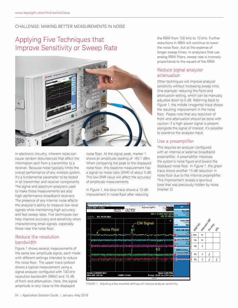
Reduce the resolution bandwidthFigure 1 shows several measurements of
the same low-amplitude signal, each made with different settings intended to reduce
the noise loor. The upper trace (yellow) shows a typical measurement using a
signal analyzer conigured with 100 kHz resolution bandwidth (RBW) and 10 dB
of front-end attenuation. Here, the signal amplitude is very close to the displayed
noise loor. At the signal peak, marker 1 shows an amplitude reading of –85.1 dBm.
When comparing the peak to the displayed
noise loor, this baseline measurement has a signal-to-noise ratio (SNR) of about 5 dB.
This low SNR value will affect the accuracy
of amplitude measurements.
In Figure 1, the blue trace shows a 10 dB improvement in noise loor after reducing
the RBW from 100 kHz to 10 kHz. Further
reductions in RBW will continue to lower
the noise loor, but at the expense of longer sweep times. In analyzers that use
analog RBW ilters, sweep rate is inversely proportional to the square of the RBW.
Reduce signal analyzer attenuationOther techniques will improve analyzer
sensitivity without increasing sweep time.
One example: reducing the front-end
attenuation setting, which can be manually adjusted down to 0 dB. Referring back to
Figure 1, the middle (magenta) trace shows the resulting improvement in the noise
loor. Please note that any reduction of front-end attenuation should be done with
caution: if a high-power signal is present
alongside the signal of interest, it’s possible to overdrive the analyzer input.
Use a preampliierThis requires an analyzer conigured with an internal or external broadband
preampliier. A preampliier improves the system’s noise igure and lowers the displayed noise loor. In Figure 1, the green trace shows another 15 dB reduction in
noise loor due to the internal preampliier. This improvement reveals a spurious
tone that was previously hidden by noise
(marker 2).
100k 10
10
0
0
0
`
` `
10k
10k
10k
10k
RBW
(Hz)
Atte
nuat
or (d
B)Pr
e-Am
pNFE
2
1
CW Signal
Noise Floor
FIGURE 1. Adjusting a few essential settings will improve analyzer sensitivity.
www.keysight.com/ind/switch2exa
Application Solution Guide | January–May 2016 | 05
CHALLENGE: MAKING BETTER MEASUREMENTS IN NOISE (CONTINUED)
Remove analyzer noise from the measured signalA feature called Noise Floor Extension
(NFE), available on Keysight’s X-Series signal analyzers, improves analyzer sensitivity. The NFE process does this
by identifying the instrument’s noise
contribution at speciic settings and then subtracting that noise from the
measurement. In Figure 1, the red trace shows a measurement with NFE activated:
the displayed noise loor is improved by another 8 dB.
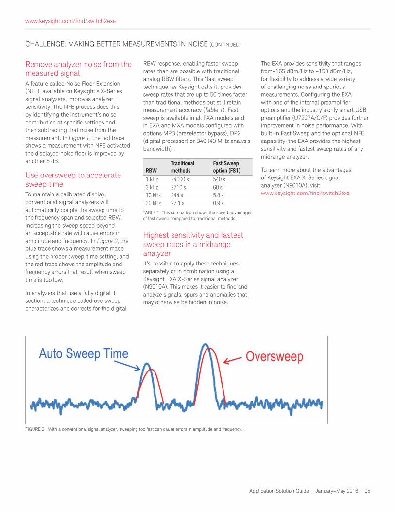
Use oversweep to accelerate sweep timeTo maintain a calibrated display, conventional signal analyzers will
automatically couple the sweep time to
the frequency span and selected RBW.
Increasing the sweep speed beyond
an acceptable rate will cause errors in
amplitude and frequency. In Figure 2, the blue trace shows a measurement made
using the proper sweep-time setting, and the red trace shows the amplitude and
frequency errors that result when sweep
time is too low.
In analyzers that use a fully digital IF
section, a technique called oversweep characterizes and corrects for the digital
RBW response, enabling faster sweep rates than are possible with traditional
analog RBW ilters. This “fast sweep” technique, as Keysight calls it, provides sweep rates that are up to 50 times faster
than traditional methods but still retain
measurement accuracy (Table 1). Fast
sweep is available in all PXA models and
in EXA and MXA models conigured with options MPB (preselector bypass), DP2 (digital processor) or B40 (40 MHz analysis
bandwidth).
Highest sensitivity and fastest sweep rates in a midrange analyzerIt’s possible to apply these techniques
separately or in combination using a
Keysight EXA X-Series signal analyzer
(N9010A). This makes it easier to ind and analyze signals, spurs and anomalies that may otherwise be hidden in noise.
The EXA provides sensitivity that ranges
from–165 dBm/Hz to –153 dBm/Hz, for lexibility to address a wide variety of challenging noise and spurious
measurements. Coniguring the EXA with one of the internal preampliier options and the industry’s only smart USB
preampliier (U7227A/C/F) provides further improvement in noise performance. With
built-in Fast Sweep and the optional NFE
capability, the EXA provides the highest sensitivity and fastest sweep rates of any
midrange analyzer.
To learn more about the advantages
of Keysight EXA X-Series signal
analyzer (N9010A), visit www.keysight.com/ind/switch2exa
FIGURE 2. With a conventional signal analyzer, sweeping too fast can cause errors in amplitude and frequency.
RBWTraditional methods
Fast Sweep option (FS1)
1 kHz >4000 s 540 s
3 kHz 2710 s 60 s
10 kHz 244 s 5.8 s
30 kHz 27.1 s 0.9 s
TABLE 1. This comparison shows the speed advantages
of fast sweep compared to traditional methods.
www.keysight.com/ind/switch2exa
06 | Application Solution Guide | January–May 2016
Depending on your application and requirements, the X-Series signal analyzers offer migration paths from many of our previous-generation spectrum/signal analyzers.
– To modernize manufacturing test systems, the EXA is an ideal replacement for the ESA-E: www.keysight.com/ind/esa2exa
– To accelerate the development of new wireless devices, the MXA expands on the performance and capabilities of the classic 8560E/EC Series: www.keysight.com/ind/856x_to_X-Series
– To upgrade test systems in R&D, manufacturing and ATE, the PXA is optimized for maximum backward compatibility—and is easily conigured as a replacement for—the E444xA PSA: www.keysight.com/ind/psa2pxa
Migrate to the X-Series
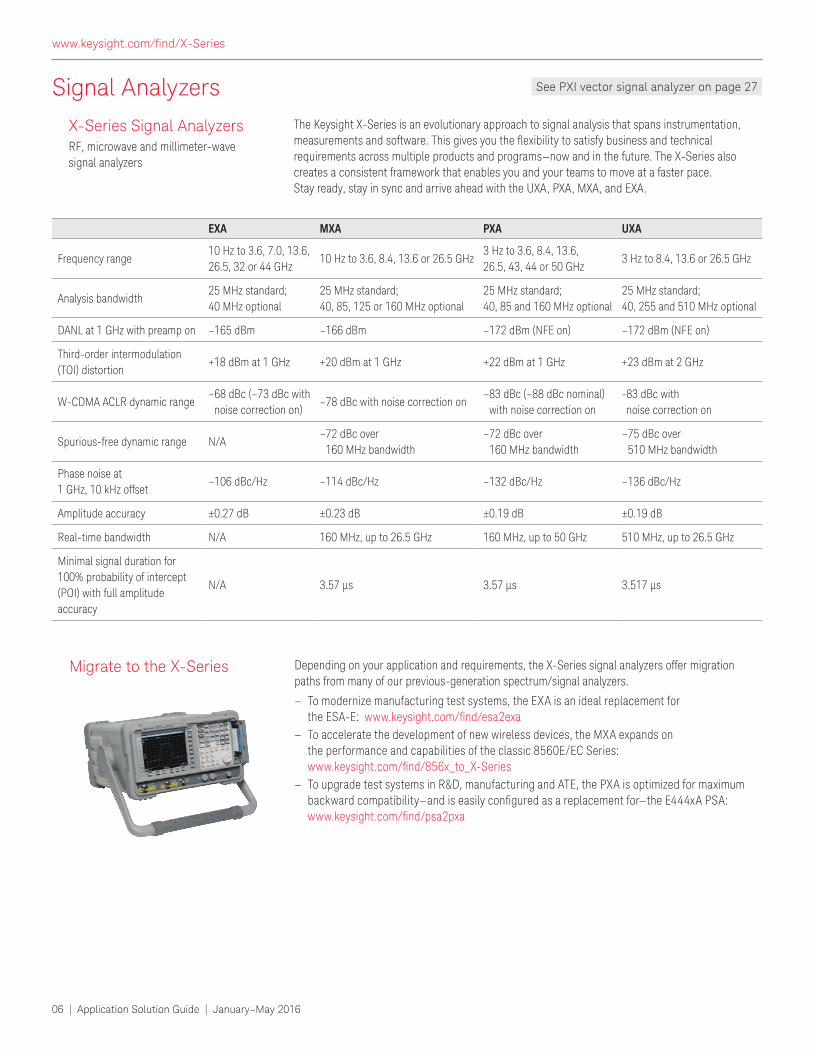
The Keysight X-Series is an evolutionary approach to signal analysis that spans instrumentation, measurements and software. This gives you the lexibility to satisfy business and technical requirements across multiple products and programs—now and in the future. The X-Series also creates a consistent framework that enables you and your teams to move at a faster pace. Stay ready, stay in sync and arrive ahead with the UXA, PXA, MXA, and EXA.
X-Series Signal AnalyzersRF, microwave and millimeter-wave signal analyzers
Signal Analyzers See PXI vector signal analyzer on page 27
EXA MXA PXA UXA
Frequency range10 Hz to 3.6, 7.0, 13.6,
26.5, 32 or 44 GHz10 Hz to 3.6, 8.4, 13.6 or 26.5 GHz
3 Hz to 3.6, 8.4, 13.6,
26.5, 43, 44 or 50 GHz3 Hz to 8.4, 13.6 or 26.5 GHz
Analysis bandwidth25 MHz standard;
40 MHz optional
25 MHz standard;
40, 85, 125 or 160 MHz optional
25 MHz standard;
40, 85 and 160 MHz optional
25 MHz standard;
40, 255 and 510 MHz optional
DANL at 1 GHz with preamp on –165 dBm –166 dBm –172 dBm (NFE on) –172 dBm (NFE on)
Third-order intermodulation
(TOI) distortion+18 dBm at 1 GHz +20 dBm at 1 GHz +22 dBm at 1 GHz +23 dBm at 2 GHz
W-CDMA ACLR dynamic range– 68 dBc (–73 dBc with
noise correction on)–78 dBc with noise correction on
– 83 dBc (–88 dBc nominal)
with noise correction on
- 83 dBc with
noise correction on
Spurious-free dynamic range N/A– 72 dBc over
160 MHz bandwidth
– 72 dBc over
160 MHz bandwidth
– 75 dBc over
510 MHz bandwidth
Phase noise at
1 GHz, 10 kHz offset–106 dBc/Hz –114 dBc/Hz –132 dBc/Hz –136 dBc/Hz
Amplitude accuracy ±0.27 dB ±0.23 dB ±0.19 dB ±0.19 dB
Real-time bandwidth N/A 160 MHz, up to 26.5 GHz 160 MHz, up to 50 GHz 510 MHz, up to 26.5 GHz
Minimal signal duration for
100% probability of intercept
(POI) with full amplitude
accuracy
N/A 3.57 µs 3.57 µs 3.517 µs
www.keysight.com/ind/X-Series
Application Solution Guide | January–May 2016 | 07
Signal Analyzers
Accelerate in wireless with the MXA
The midrange MXA is the optimum choice in wireless as you develop devices and deliver them to manufacturing and the marketplace. It has the lexibility to quickly adapt to your evolving test requirements—today and tomorrow.
– Optimized for fast power measurements such as channel power, adjacent channel power, occupied bandwidth and harmonics
– Shorten test times with rapid local measurements, display updates and marker peak searches
– Achieve low internal error vector magnitude (EVM) loor with best-in-class phase noise of –114 dBc/Hz
MXA X-Series Signal Analyzer
N9020A
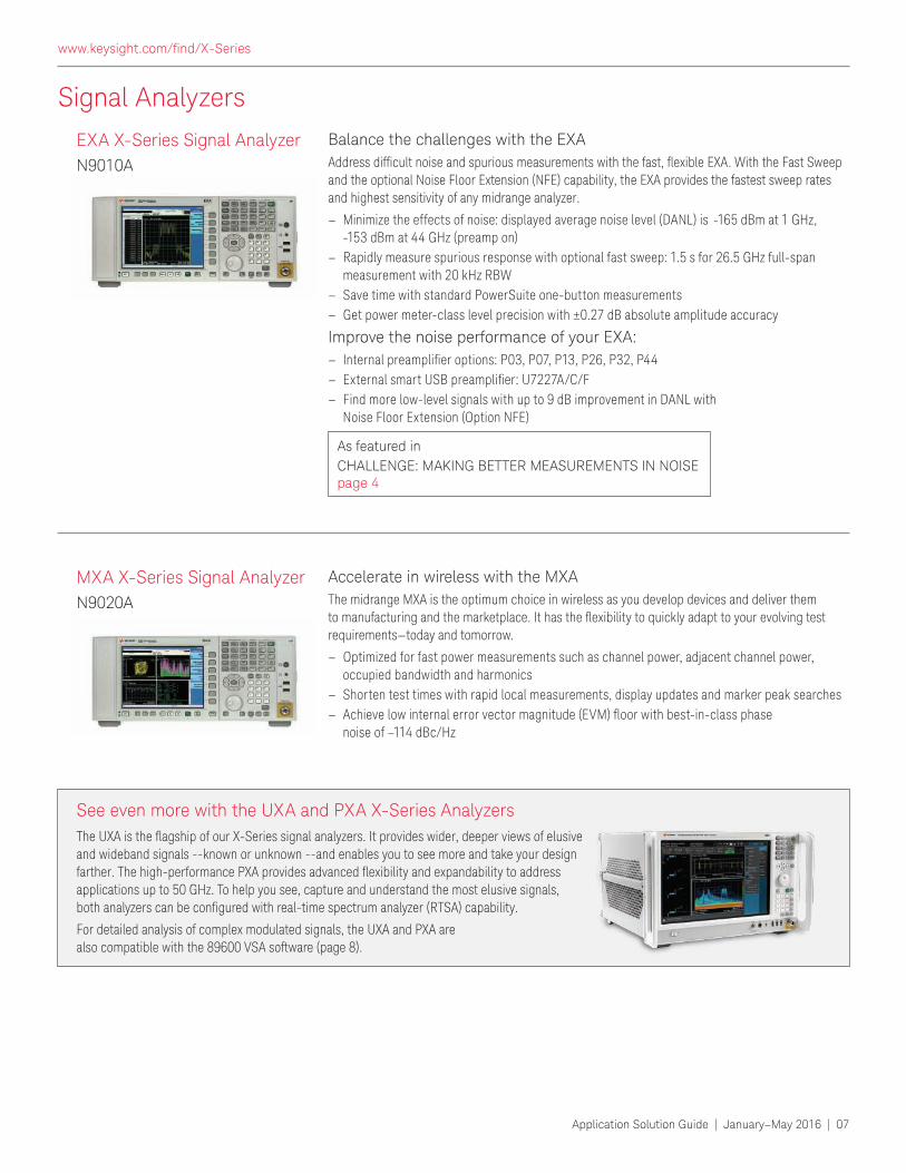
Balance the challenges with the EXA
Address dificult noise and spurious measurements with the fast, lexible EXA. With the Fast Sweep and the optional Noise Floor Extension (NFE) capability, the EXA provides the fastest sweep rates and highest sensitivity of any midrange analyzer.
– Minimize the effects of noise: displayed average noise level (DANL) is -165 dBm at 1 GHz, -153 dBm at 44 GHz (preamp on)
– Rapidly measure spurious response with optional fast sweep: 1.5 s for 26.5 GHz full-span measurement with 20 kHz RBW
– Save time with standard PowerSuite one-button measurements
– Get power meter-class level precision with ±0.27 dB absolute amplitude accuracy
Improve the noise performance of your EXA:
– Internal preampliier options: P03, P07, P13, P26, P32, P44 – External smart USB preampliier: U7227A/C/F – Find more low-level signals with up to 9 dB improvement in DANL with
Noise Floor Extension (Option NFE)
EXA X-Series Signal Analyzer
N9010A
As featured in
CHALLENGE: MAKING BETTER MEASUREMENTS IN NOISE page 4
The UXA is the lagship of our X-Series signal analyzers. It provides wider, deeper views of elusive and wideband signals --known or unknown --and enables you to see more and take your design farther. The high-performance PXA provides advanced lexibility and expandability to address applications up to 50 GHz. To help you see, capture and understand the most elusive signals, both analyzers can be conigured with real-time spectrum analyzer (RTSA) capability.
For detailed analysis of complex modulated signals, the UXA and PXA are also compatible with the 89600 VSA software (page 8).
See even more with the UXA and PXA X-Series Analyzers
www.keysight.com/ind/X-Series
08 | Application Solution Guide | January–May 2016
Signal Analyzer/Signal Generator Apps and Software
Keysight software is downloadable expertise. www.keysight.com/ind/software
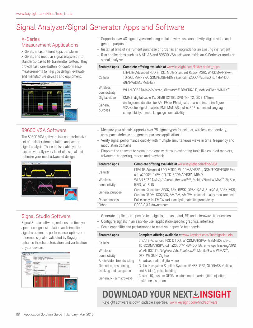
– Supports over 40 signal types including cellular, wireless connectivity, digital video and general purpose
– Install at time of instrument purchase or order as an upgrade for an existing instrument
– Run applications such as MATLAB and 89600 VSA software inside an X-Series or modular signal analyzer
X-Series Measurement ApplicationsX-Series measurement apps transform X-Series and modular signal analyzers into standards-based RF transmitter testers. They provide fast, one-button RF conformance measurements to help you design, evaluate, and manufacture devices and equipment.
Featured apps Complete offering available at www.keysight.com/ind/x-series_apps
Cellular
LTE/LTE-Advanced FDD & TDD, Multi-Standard Radio (MSR), W-CDMA/HSPA+,
TD-SCDMA/HSPA, GSM/EDGE/EDGE Evo, cdma2000®/cdmaOne, 1xEV-DO,
iDEN/WiDEN/MotoTalk
Wireless
connectivityWLAN 802.11a/b/g/n/ac/ah, Bluetooth® BR/EDR/LE, Mobile/Fixed WiMAX™
Digital video CMMB, digital cable TV, DTMB (CTTB), DVB-T/H T2, ISDB-T/Tmm
General
purpose
Analog demodulation for AM, FM or PM signals, phase noise, noise igure, VXA vector signal analysis, EMI, MATLAB, pulse, SCPI command language
compatibility, remote language compatibility
– Measure your signal: supports over 75 signal types for cellular, wireless connectivity, aerospace, defense and general purpose applications
– Verify signal performance quickly with multiple simultaneous views in time, frequency and modulation domains
– Pinpoint the answers to signal problems with troubleshooting tools like coupled markers, advanced triggering, record and playback
89600 VSA SoftwareThe 89600 VSA software is a comprehensive set of tools for demodulation and vector signal analysis. These tools enable you to explore virtually every facet of a signal and optimize your most advanced designs.
Featured apps Complete offering available at www.keysight.com/ind/VSA
CellularLTE/LTE-Advanced FDD & TDD, W-CDMA/HSPA+, GSM/EDGE/EDGE Evo,
cdma2000®, 1xEV-DO, TD-SCDMA/HSPA, MIMO
Wireless
connectivity
WLAN 802.11a/b/g/n/ac/ah, Bluetooth®, Mobile/Fixed WiMAX™, ZigBee,
RFID, Wi-SUN
General purposeCustom IQ, custom APSK, FSK, BPSK, QPSK, QAM, StarQAM, APSK, VSB,
Custom OFDM, SOQPSK, AM/AM, AM/PM, channel quality measurements
Radar analysis Pulse analysis, FMCW radar analysis, satellite group delay
Other DOCSIS 3.1 downstream
– Generate application-speciic test signals, at baseband, RF, and microwave frequencies – Conigure signals in an easy-to-use, application-speciic graphical interface – Scale capability and performance to meet your speciic test needs
Signal Studio SoftwareSignal Studio software, reduces the time you spend on signal simulation and simpliies signal creation. Its performance-optimized reference signals—validated by Keysight— enhance the characterization and veriication of your devices.
Featured apps Complete offering available at www.keysight.com/ind/signalstudio
Cellular LTE/LTE-Advanced FDD & TDD, W-CDMA/HSPA+, GSM/EDGE/Evo,
TD-SCDMA/HSPA, cdma2000®/1xEV-DO, 5G, envelope tracking/DPD
Wireless
connectivity
WLAN 802.11a/b/g/n/ac/ah, Bluetooth®, Mobile/Fixed WiMAX™,
DFS, Wi-SUN, ZigBee
Audio/video broadcasting Broadcast radio, digital video
Detection, positioning,
tracking and navigation
Global Navigation Satellite Systems (GNSS: GPS, GLONASS, Galileo,
and Beidou), pulse building
General RF & microwaveCustom IQ, custom OFDM, custom multi-carrier, jitter injection,
multitone distortion
www.keysight.com/ind/free_trials
Application Solution Guide | January–May 2016 | 09
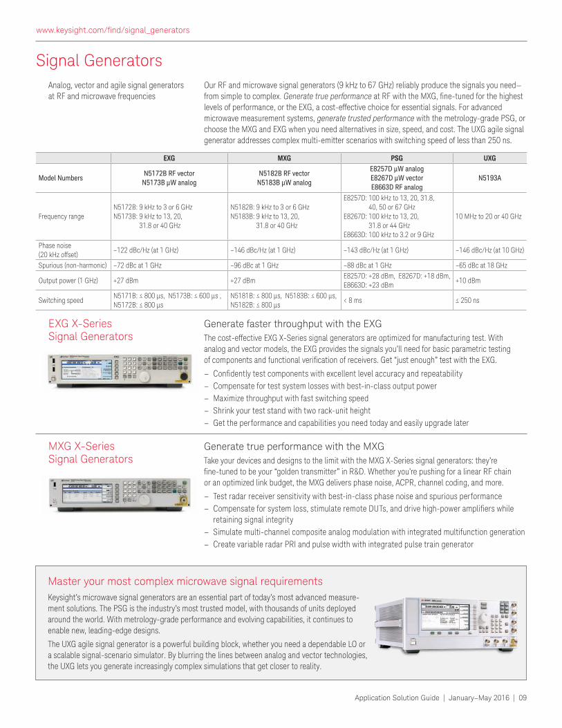
Signal Generators
EXG MXG PSG UXG
Model NumbersN5172B RF vector
N5173B μW analogN5182B RF vector
N5183B μW analog
E8257D μW analog E8267D μW vector E8663D RF analog
N5193A
Frequency rangeN5172B: 9 kHz to 3 or 6 GHzN5173B: 9 kHz to 13, 20,
31.8 or 40 GHz
N5182B: 9 kHz to 3 or 6 GHzN5183B: 9 kHz to 13, 20,
31.8 or 40 GHz
E8257D: 100 kHz to 13, 20, 31.8, 40, 50 or 67 GHz
E8267D: 100 kHz to 13, 20, 31.8 or 44 GHz
E8663D: 100 kHz to 3.2 or 9 GHz
10 MHz to 20 or 40 GHz
Phase noise (20 kHz offset)
–122 dBc/Hz (at 1 GHz) –146 dBc/Hz (at 1 GHz) –143 dBc/Hz (at 1 GHz) –146 dBc/Hz (at 10 GHz)
Spurious (non-harmonic) –72 dBc at 1 GHz –96 dBc at 1 GHz –88 dBc at 1 GHz –65 dBc at 18 GHz
Output power (1 GHz) +27 dBm +27 dBmE8257D: +28 dBm, E8267D: +18 dBm, E8663D: +23 dBm
+10 dBm
Switching speedN5171B: ≤ 800 µs, N5173B: ≤ 600 µs , N5172B: ≤ 800 µs
N5181B: ≤ 800 µs, N5183B: ≤ 600 µs, N5182B: ≤ 800 µs
< 8 ms ≤ 250 ns
Generate true performance with the MXG
Take your devices and designs to the limit with the MXG X-Series signal generators: they’re ine-tuned to be your “golden transmitter” in R&D. Whether you’re pushing for a linear RF chain or an optimized link budget, the MXG delivers phase noise, ACPR, channel coding, and more.
– Test radar receiver sensitivity with best-in-class phase noise and spurious performance
– Compensate for system loss, stimulate remote DUTs, and drive high-power ampliiers while retaining signal integrity
– Simulate multi-channel composite analog modulation with integrated multifunction generation
– Create variable radar PRI and pulse width with integrated pulse train generator
MXG X-Series Signal Generators
Generate faster throughput with the EXG
The cost-effective EXG X-Series signal generators are optimized for manufacturing test. With analog and vector models, the EXG provides the signals you’ll need for basic parametric testing of components and functional veriication of receivers. Get “just enough” test with the EXG.
– Conidently test components with excellent level accuracy and repeatability – Compensate for test system losses with best-in-class output power
– Maximize throughput with fast switching speed
– Shrink your test stand with two rack-unit height
– Get the performance and capabilities you need today and easily upgrade later
EXG X-Series Signal Generators
Our RF and microwave signal generators (9 kHz to 67 GHz) reliably produce the signals you need—from simple to complex. Generate true performance at RF with the MXG, ine-tuned for the highest levels of performance, or the EXG, a cost-effective choice for essential signals. For advanced microwave measurement systems, generate trusted performance with the metrology-grade PSG, or choose the MXG and EXG when you need alternatives in size, speed, and cost. The UXG agile signal generator addresses complex multi-emitter scenarios with switching speed of less than 250 ns.
Analog, vector and agile signal generators at RF and microwave frequencies
Keysight’s microwave signal generators are an essential part of today’s most advanced measure-ment solutions. The PSG is the industry’s most trusted model, with thousands of units deployed around the world. With metrology-grade performance and evolving capabilities, it continues to enable new, leading-edge designs.
The UXG agile signal generator is a powerful building block, whether you need a dependable LO or a scalable signal-scenario simulator. By blurring the lines between analog and vector technologies, the UXG lets you generate increasingly complex simulations that get closer to reality.
Master your most complex microwave signal requirements
www.keysight.com/ind/signal_generators
10 | Application Solution Guide | January–May 2016
Making Better Ripple and Noise Measurements on DC Voltage Rails
In every integrated circuit (IC), power is a tightly controlled commodity. As demand
for longer battery life, more features and improved performance increase, the burden falls to designers to reduce power
consumption on their internal power
distribution network (PDN).
To reduce power consumption, voltages and tolerances have gotten smaller: many
of today’s designs have 3.3 V, 1.8 V and even 1.1 V supplies. As output voltages
have become smaller, so have their tolerances, dropping from 10% to as low as 1%. Ensuring a clean power rail that stays
within the tolerance band depends on the
ability to identify and reduce ripple, noise and transients—and this requires tools that
make it possible to see and characterize
small signals riding on the DC power rails.
A key test challenge: Measuring small AC signals riding on DCEvery circuit that depends on DC power
has a tolerance band around the expected
value of the supply voltage. As long as
ripple, noise or transients stay within the band, the PDN will pass tolerance testing.
If the unwanted signals exceed
the band limit, then it’s time to investigate the problem.
An oscilloscope is often the best
way to measure small AC signals
riding on a DC level. To ensure
accurate measurements, the noise in the total oscilloscope
measurement system—
instrument, cable and probe—needs to be well below the
signal level. The following tips
will help improve your resolution
on AC signals.
Use a 1:1 probeOscilloscope probes are available
in a variety of attenuation ratios, and the ratio indicates the
division factor applied by the
probe. For example, a 10:1 probe divides the input by 10, enabling measurements of signals that
might otherwise exceed the
oscilloscope’s maximum input
level.
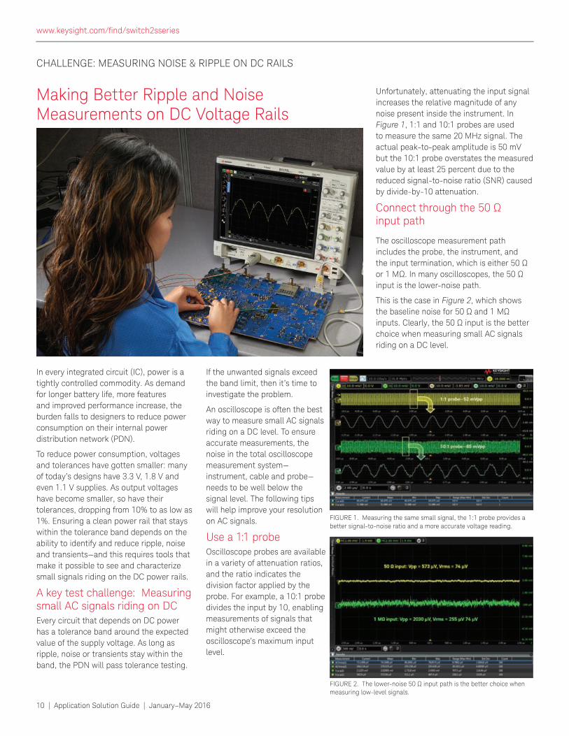
Unfortunately, attenuating the input signal increases the relative magnitude of any
noise present inside the instrument. In
Figure 1, 1:1 and 10:1 probes are used to measure the same 20 MHz signal. The
actual peak-to-peak amplitude is 50 mV
but the 10:1 probe overstates the measured
value by at least 25 percent due to the
reduced signal-to-noise ratio (SNR) caused
by divide-by-10 attenuation.
Connect through the 50 Ω input path
The oscilloscope measurement path
includes the probe, the instrument, and the input termination, which is either 50 Ω or 1 MΩ. In many oscilloscopes, the 50 Ω input is the lower-noise path.
This is the case in Figure 2, which shows the baseline noise for 50 Ω and 1 MΩ inputs. Clearly, the 50 Ω input is the better choice when measuring small AC signals
riding on a DC level.
CHALLENGE: MEASURING NOISE & RIPPLE ON DC RAILS
FIGURE 1. Measuring the same small signal, the 1:1 probe provides a better signal-to-noise ratio and a more accurate voltage reading.
FIGURE 2. The lower-noise 50 Ω input path is the better choice when measuring low-level signals.
www.keysight.com/ind/switch2sseries
Application Solution Guide | January–May 2016 | 11
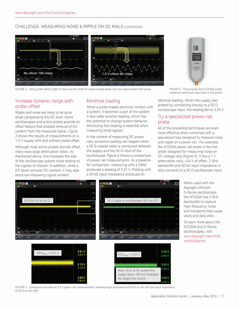
Increase dynamic range with probe offsetRipple and noise are likely to be quite
small compared to the DC level. Some
oscilloscopes and active probes provide an
offset feature that enables removal of DC
content from the measured signal. Figure
3 shows the results of measurements on a
1.5 V supply with and without probe offset.
Although most active probes provide offset, many have large attenuation ratios. As
mentioned above, this increases the size of the oscilloscope system noise relative to
the signals of interest. In addition, while a DC block removes DC content, it may also block low-frequency signal content.
Minimize loading When a probe makes electrical contact with
a system, it becomes a part of the system. It also adds resistive loading, which has the potential to change system behavior.
Minimizing this loading is essential when
measuring small signals.
In the context of measuring DC power
rails, excessive loading can happen when a 50 Ω coaxial cable is connected between the supply and the 50 Ω input of the oscilloscope. Figure 4 shows a comparison
of power-rail measurements. As a baseline
for comparison, measuring with a DMM produced a reading of 3.31 V. Probing with
a 50 kΩ input impedance produced an
identical reading. When the supply was
probed by connecting directly to a 50 Ω oscilloscope input, the reading fell to 3.25 V.
Try a specialized power-rail probeAll of the preceding techniques are even
more effective when combined with a
specialized tool designed to measure noise
and ripple on a power rail . For example, the N7020A power rail probe is the irst probe designed for measuring noise on
DC voltage rails (Figure 5). It has a 1:1
attenuation ratio, ±24 V of offset, 2 GHz bandwidth and 50 kΩ input impedance; it also connects to a 50 Ω oscilloscope input.
When used with the
Keysight Ininiium S-Series oscilloscope, the N7020A has 2 GHz
bandwidth to capture
high-frequency noise
and transients that cause
clock and data jitter.
To learn more about the
N7020A and S-Series
oscilloscopes, visit: www.keysight.com/ind/switch2sseries
CHALLENGE: MEASURING NOISE & RIPPLE ON DC RAILS (CONTINUED)
FIGURE 3. Using probe offset (right) to focus on the small AC signal reveals detail that can help pinpoint the cause.
FIGURE 4. Comparison of noise on 3.3 V power rail measurements, showing input impedance of 50 kΩ on the left and input impedance of 50 Ω on the right.
FIGURE 5. The purpose-built N7020A probe
enhances techniques described in the article.
www.keysight.com/ind/switch2sseries
N7020A 50 kΩ at DC 50 Ω cable to oscilloscope (50 Ω at DC)
3.61 V
3.13 V
2.63 V 3.00 V
3.20 V
3.40 VDCVrms = 3.31 V DCVrms = 3.25 V
Note: 50 Ω at DC pulled this supply down ~60 mV (changed
the target this much)
12 | Application Solution Guide | January–May 2016
Oscilloscopes
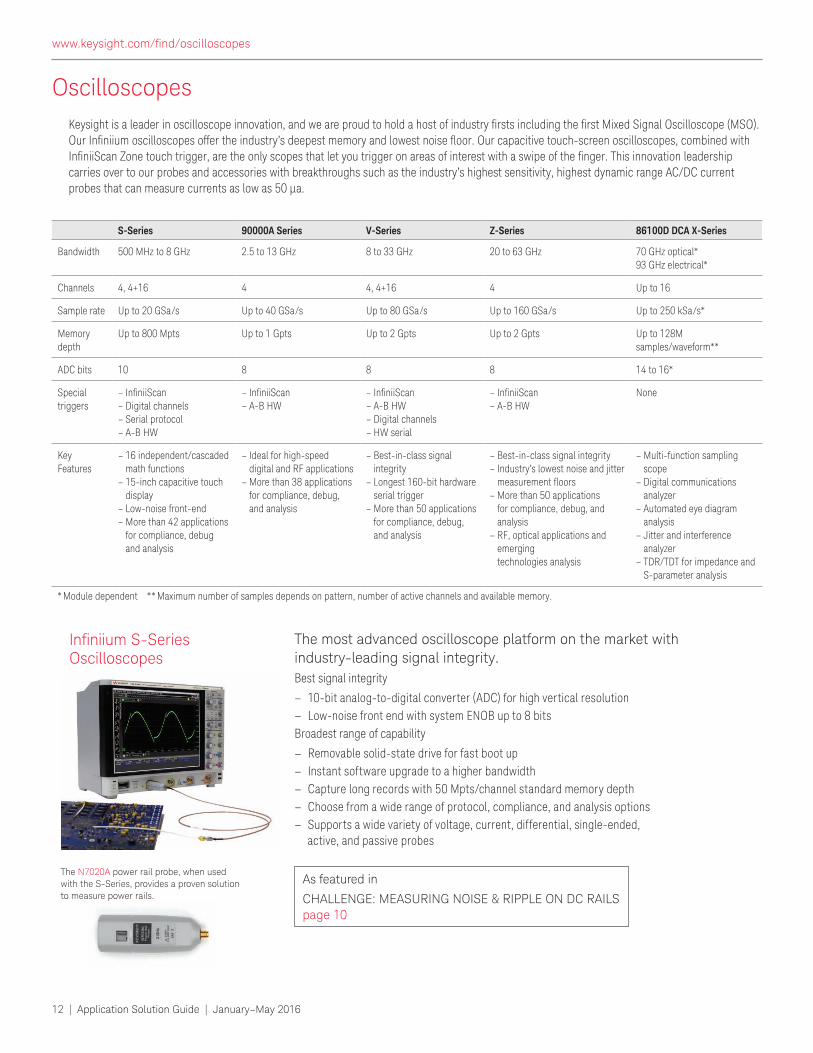
The most advanced oscilloscope platform on the market with
industry-leading signal integrity.
Best signal integrity
– 10-bit analog-to-digital converter (ADC) for high vertical resolution
– Low-noise front end with system ENOB up to 8 bits
Broadest range of capability
– Removable solid-state drive for fast boot up
– Instant software upgrade to a higher bandwidth
– Capture long records with 50 Mpts/channel standard memory depth
– Choose from a wide range of protocol, compliance, and analysis options
– Supports a wide variety of voltage, current, differential, single-ended, active, and passive probes
Ininiium S-Series Oscilloscopes
The N7020A power rail probe, when used with the S-Series, provides a proven solution to measure power rails.
As featured in
CHALLENGE: MEASURING NOISE & RIPPLE ON DC RAILS page 10
Keysight is a leader in oscilloscope innovation, and we are proud to hold a host of industry irsts including the irst Mixed Signal Oscilloscope (MSO). Our Ininiium oscilloscopes offer the industry’s deepest memory and lowest noise loor. Our capacitive touch-screen oscilloscopes, combined with IniniiScan Zone touch trigger, are the only scopes that let you trigger on areas of interest with a swipe of the inger. This innovation leadership carries over to our probes and accessories with breakthroughs such as the industry’s highest sensitivity, highest dynamic range AC/DC current probes that can measure currents as low as 50 μa.
S-Series 90000A Series V-Series Z-Series 86100D DCA X-Series
Bandwidth 500 MHz to 8 GHz 2.5 to 13 GHz 8 to 33 GHz 20 to 63 GHz 70 GHz optical* 93 GHz electrical*
Channels 4, 4+16 4 4, 4+16 4 Up to 16
Sample rate Up to 20 GSa/s Up to 40 GSa/s Up to 80 GSa/s Up to 160 GSa/s Up to 250 kSa/s*
Memory depth
Up to 800 Mpts Up to 1 Gpts Up to 2 Gpts Up to 2 Gpts Up to 128M samples/waveform**
ADC bits 10 8 8 8 14 to 16*
Special triggers
– IniniiScan – Digital channels – Serial protocol – A-B HW
– IniniiScan – A-B HW
– IniniiScan – A-B HW – Digital channels – HW serial
– IniniiScan – A-B HW
None
Key Features
– 16 independent/cascaded math functions – 15-inch capacitive touch display – Low-noise front-end – More than 42 applications for compliance, debug and analysis
– Ideal for high-speed digital and RF applications – More than 38 applications for compliance, debug, and analysis
– Best-in-class signal integrity – Longest 160-bit hardware serial trigger – More than 50 applications for compliance, debug, and analysis
– Best-in-class signal integrity – Industry’s lowest noise and jitter measurement loors – More than 50 applications for compliance, debug, and analysis – RF, optical applications and emerging technologies analysis
– Multi-function sampling scope – Digital communications analyzer – Automated eye diagram analysis – Jitter and interference analyzer – TDR/TDT for impedance and S-parameter analysis
* Module dependent ** Maximum number of samples depends on pattern, number of active channels and available memory.
www.keysight.com/ind/oscilloscopes
Application Solution Guide | January–May 2016 | 13
Oscilloscopes
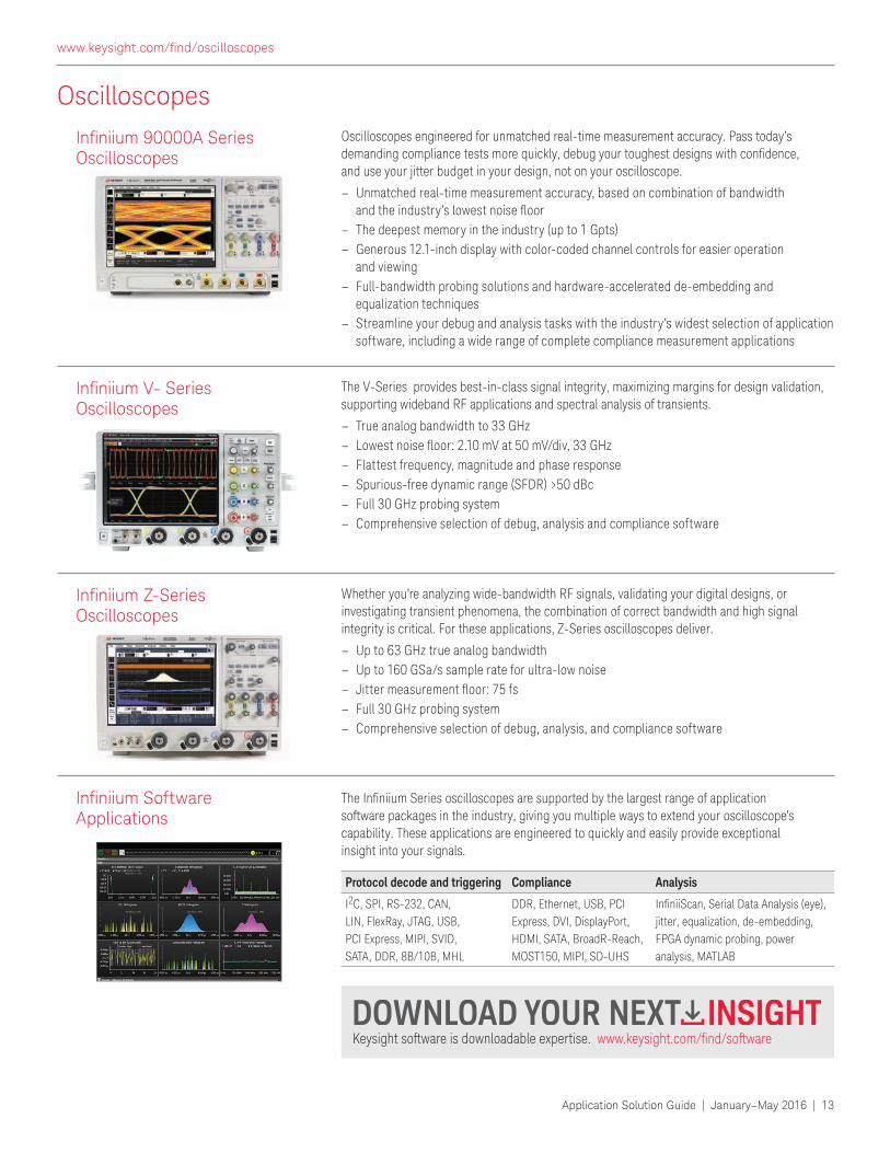
Whether you’re analyzing wide-bandwidth RF signals, validating your digital designs, or investigating transient phenomena, the combination of correct bandwidth and high signal integrity is critical. For these applications, Z-Series oscilloscopes deliver.
– Up to 63 GHz true analog bandwidth
– Up to 160 GSa/s sample rate for ultra-low noise
– Jitter measurement loor: 75 fs – Full 30 GHz probing system
– Comprehensive selection of debug, analysis, and compliance software
Ininiium Z-Series Oscilloscopes
Oscilloscopes engineered for unmatched real-time measurement accuracy. Pass today’s demanding compliance tests more quickly, debug your toughest designs with conidence, and use your jitter budget in your design, not on your oscilloscope.
– Unmatched real-time measurement accuracy, based on combination of bandwidth and the industry’s lowest noise loor
– The deepest memory in the industry (up to 1 Gpts)
– Generous 12.1-inch display with color-coded channel controls for easier operation and viewing
– Full-bandwidth probing solutions and hardware-accelerated de-embedding and equalization techniques
– Streamline your debug and analysis tasks with the industry’s widest selection of application software, including a wide range of complete compliance measurement applications
Ininiium 90000A Series Oscilloscopes
The V-Series provides best-in-class signal integrity, maximizing margins for design validation, supporting wideband RF applications and spectral analysis of transients.
– True analog bandwidth to 33 GHz
– Lowest noise loor: 2.10 mV at 50 mV/div, 33 GHz – Flattest frequency, magnitude and phase response
– Spurious-free dynamic range (SFDR) >50 dBc
– Full 30 GHz probing system
– Comprehensive selection of debug, analysis and compliance software
Ininiium V- Series Oscilloscopes
Keysight software is downloadable expertise. www.keysight.com/ind/software
The Ininiium Series oscilloscopes are supported by the largest range of application software packages in the industry, giving you multiple ways to extend your oscilloscope’s capability. These applications are engineered to quickly and easily provide exceptional insight into your signals.
Ininiium Software Applications
Protocol decode and triggering Compliance Analysis
I2C, SPI, RS-232, CAN,
LIN, FlexRay, JTAG, USB,
PCI Express, MIPI, SVID,
SATA, DDR, 8B/10B, MHL
DDR, Ethernet, USB, PCI
Express, DVI, DisplayPort,
HDMI, SATA, BroadR-Reach,
MOST150, MIPI, SD-UHS
IniniiScan, Serial Data Analysis (eye), jitter, equalization, de-embedding,
FPGA dynamic probing, power
analysis, MATLAB
www.keysight.com/ind/oscilloscopes
14 | Application Solution Guide | January–May 2016
Logic Analyzers
Timing analysis (asynchronous sampling)
– 2.5 GHz/5 GHz (400 ps/200 ps) conventional and transitional timing analysis in deep memory (full/half channel)
– Up to 128 M/256 M deep memory (full/half channel)
– 12.5 GHz (80 ps) Timing Zoom with 256 K memory
State analysis (synchronous sampling)
– 350 MHz state clock/700 Mbps data rate (standard)
– 700 MHz state clock/1400 Mbps data rate (optional)
– Up to 128 M deep memory
– Reliable measurements on eye openings as small as 200 ps by 100 mV
Probing
– Single-ended direct connect lying lead, Mictor, and Soft Touch Pro connectorless probes – Compatible with U4201A cable plus any 90-pin header single-ended or differential probes
Applications
– General digital debug and validation
– FPGA debug (automated analyzer setup for Xilinx ISE designs and Altera Quartus designs)
– DDR2/3 1333 ADD/CMD/Data Decode, Debug, Functional Compliance test, and Performance Analysis
– LPDDR/2/3 1333 ADD/CMD/Data Decode, Debug, Functional Compliance test, and Performance Analysis
– Digital I/Q baseband signal capture and 89600 VSA software for signal demodulation and vector signal analysis
Portable Logic Analyzer 16850 Series
The industry’s fastest timing capture with deep memory—for fast digital system debug.
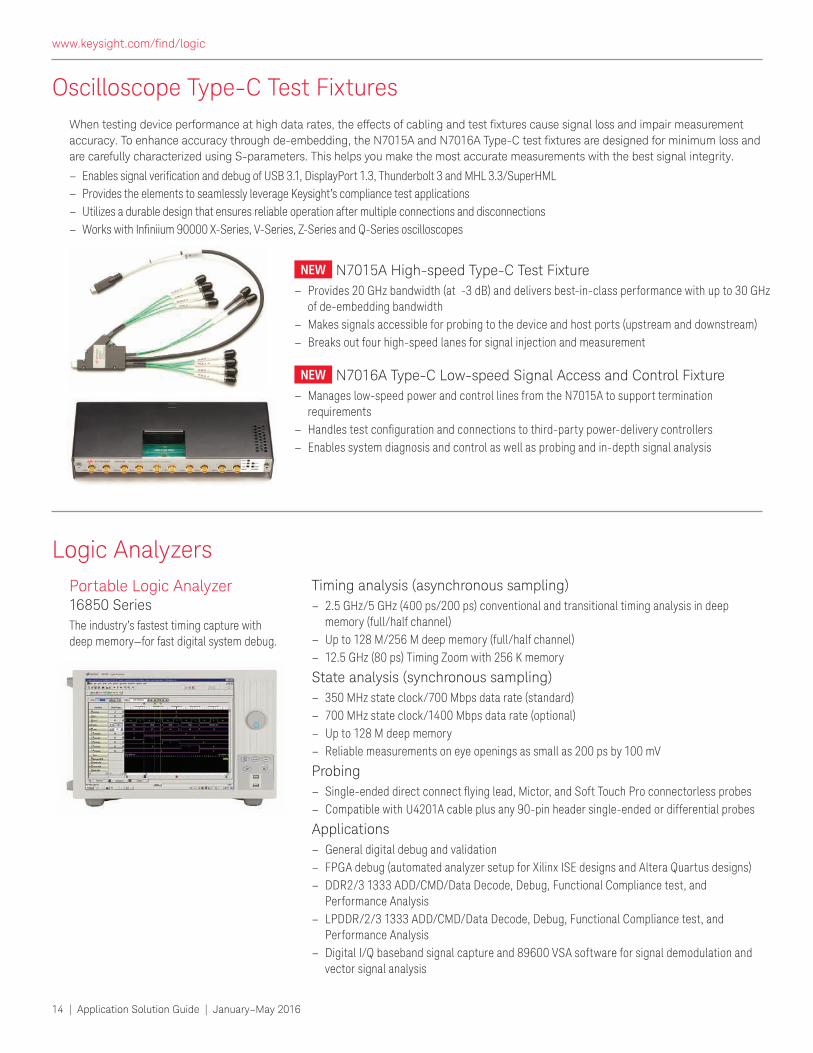
NEW N7015A High-speed Type-C Test Fixture
– Provides 20 GHz bandwidth (at -3 dB) and delivers best-in-class performance with up to 30 GHz of de-embedding bandwidth
– Makes signals accessible for probing to the device and host ports (upstream and downstream)
– Breaks out four high-speed lanes for signal injection and measurement
NEW N7016A Type-C Low-speed Signal Access and Control Fixture
– Manages low-speed power and control lines from the N7015A to support termination requirements
– Handles test coniguration and connections to third-party power-delivery controllers – Enables system diagnosis and control as well as probing and in-depth signal analysis
Oscilloscope Type-C Test Fixtures
When testing device performance at high data rates, the effects of cabling and test ixtures cause signal loss and impair measurement accuracy. To enhance accuracy through de-embedding, the N7015A and N7016A Type-C test ixtures are designed for minimum loss and are carefully characterized using S-parameters. This helps you make the most accurate measurements with the best signal integrity.
– Enables signal veriication and debug of USB 3.1, DisplayPort 1.3, Thunderbolt 3 and MHL 3.3/SuperHML – Provides the elements to seamlessly leverage Keysight’s compliance test applications
– Utilizes a durable design that ensures reliable operation after multiple connections and disconnections
– Works with Ininiium 90000 X-Series, V-Series, Z-Series and Q-Series oscilloscopes
www.keysight.com/ind/logic
Application Solution Guide | January–May 2016 | 15
Pulse Function and Arbitrary Waveform Generators
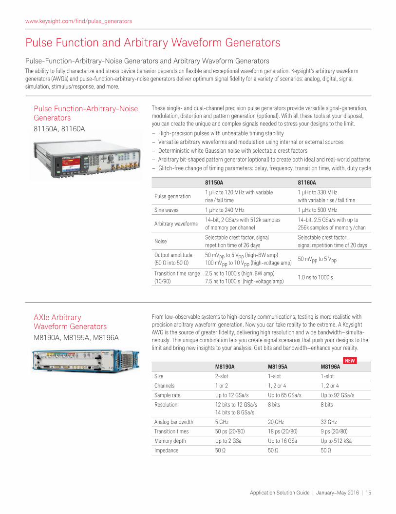
These single- and dual-channel precision pulse generators provide versatile signal-generation, modulation, distortion and pattern generation (optional). With all these tools at your disposal, you can create the unique and complex signals needed to stress your designs to the limit.
– High-precision pulses with unbeatable timing stability
– Versatile arbitrary waveforms and modulation using internal or external sources
– Deterministic white Gaussian noise with selectable crest factors
– Arbitrary bit-shaped pattern generator (optional) to create both ideal and real-world patterns
– Glitch-free change of timing parameters: delay, frequency, transition time, width, duty cycle
Pulse Function-Arbitrary-Noise Generators
81150A, 81160A
Pulse-Function-Arbitrary-Noise Generators and Arbitrary Waveform Generators
The ability to fully characterize and stress device behavior depends on lexible and exceptional waveform generation. Keysight’s arbitrary waveform generators (AWGs) and pulse-function-arbitrary-noise generators deliver optimum signal idelity for a variety of scenarios: analog, digital, signal simulation, stimulus/response, and more.
AXIe Arbitrary Waveform Generators
M8190A, M8195A, M8196A
From low-observable systems to high-density communications, testing is more realistic with precision arbitrary waveform generation. Now you can take reality to the extreme. A Keysight AWG is the source of greater idelity, delivering high resolution and wide bandwidth—simulta-neously. This unique combination lets you create signal scenarios that push your designs to the limit and bring new insights to your analysis. Get bits and bandwidth—enhance your reality.
81150A 81160A
Pulse generation1 µHz to 120 MHz with variable
rise / fall time
1 µHz to 330 MHz
with variable rise / fall time
Sine waves 1 µHz to 240 MHz 1 µHz to 500 MHz
Arbitrary waveforms14-bit, 2 GSa/s with 512k samples
of memory per channel
14-bit, 2.5 GSa/s with up to
256k samples of memory / chan
Noise Selectable crest factor, signal
repetition time of 26 days
Selectable crest factor,
signal repetition time of 20 days
Output amplitude
(50 Ω into 50 Ω)50 mVpp to 5 Vpp (high-BW amp)
100 mVpp to 10 Vpp (high-voltage amp)50 mVpp to 5 Vpp
Transition time range
(10/90)
2.5 ns to 1000 s (high-BW amp)
7.5 ns to 1000 s (high-voltage amp)1.0 ns to 1000 s
M8190A M8195A M8196A
Size 2-slot 1-slot 1-slot
Channels 1 or 2 1, 2 or 4 1, 2 or 4
Sample rate Up to 12 GSa/s Up to 65 GSa/s Up to 92 GSa/s
Resolution 12 bits to 12 GSa/s
14 bits to 8 GSa/s
8 bits 8 bits
Analog bandwidth 5 GHz 20 GHz 32 GHz
Transition times 50 ps (20/80) 18 ps (20/80) 9 ps (20/80)
Memory depth Up to 2 GSa Up to 16 GSa Up to 512 kSa
Impedance 50 Ω 50 Ω 50 Ω
NEW
www.keysight.com/ind/pulse_generators

16 | Application Solution Guide | January–May 2016
Using Permittivity Measurements to Determine Soil Composition
Whenever the price of crude oil rises, so does the interest in alternative energy
sources. One form of alternative energy
comes from oil shale, a ine-grained sedimentary rock containing a solid
mixture of organic compounds that
can be processed to produce the liquid
hydrocarbon called shale oil. Shale oil is a
substitute for crude oil but the extraction
process is more costly. So, it is important to test shale rock samples and characterize
the oil content.
A key test challenge: Characterizing complex materialsSoil materials, such as rock and clay, have electrical and mechanical properties that
depend on their organic and inorganic
composition, as well as the binding conditions. They often exhibit insulating
and conducting properties consistent with
dielectric materials. This makes it possible
to measure and determine the dielectric
constant or permittivity of a sample, and the permittivity of every material has a
characteristic frequency response.
These measurements can be made
electrically but there are several important
challenges. One is the need to make
measurements that may range from tens
of hertz to a few gigahertz, to better understand the distinctive features that
correspond to a material’s physical
properties. The other is the availability of
suitable test ixtures and sample holders that ensure high-quality measurements.
Deriving physical properties from electrical measurementsRocks and clay are composite materials
that contain moisture in the grain
boundaries, and that’s where dissolved conductive ions reside. Applying an electric
current creates conductivity by causing the
ions to move through the water (Figure 1).
As the water molecules change their
orientation, they exhibit some level of polarization. The relative permittivity of this
polarization is large compared to that of
vacuum, reaching about 80 below 100 MHz.
Conductivity and permittivity values
depend on the types of ions and molecules
present in the sample. They also depend on
characteristics such as porosity and ease
of movement. From this, a measurement of permittivity can be transformed into useful
information about physical properties such
as material composition and moisture
content—water, oil, and other luids.
Coniguring a dependable measurement solution
A variety of techniques are commonly used
to measure the permittivity of electronic
material. Some of these can be used to
characterize soil material .
At low frequencies, the parallel-plate capacitance method is widely used. A
capacitor is formed by sandwiching the
sample between two electrodes, and the permittivity is derived from an impedance
measurement (Figure 2).
For frequencies up to 30 MHz, one proven solution is the Keysight E4990A impedance
analyzer combined with the 16451B
dielectric test ixture and a dielectric sample holder from Material-Wave
Interaction Laboratories (MWI Lab). This
coniguration can measure powder samples and sheet formed solid samples that have
polished surfaces.
Open-ended coaxial probes are well-suited
to measurements of complex permittivity at
higher frequencies. The Keysight N1501A
CHALLENGE: MEASURING COMPOSITE MATERIALS
FIGURE 1. This igure illustrates the inner workings of soil material and the electrical properties that enable permittivity measurements.
www.keysight.com/ind/materials
Application Solution Guide | January–May 2016 | 17
Learn more:
Keysight Material Measurement Solutions:
www.keysight.com/ind/materials
Material-Wave Interaction Laboratories
(MWI Lab)
www.mwilab.com
of ground-penetrating radar systems, usually from 10 MHz to 10 GHz.
Base on the properties of soil material, ixturing and analysis method are required to Keysight and our solution partners’
ixtures and software along with technical experience in the electronic measurement
area will help the customers in these
research areas characterize materials.
dielectric probe kit with the N1500A option
004 materials measurement software can
be conigured to cover frequencies from 10 MHz up to 50 GHz. No special ixturing is required: measurements are made by
pressing the probe tip onto the surface of
the sample or by immersing the probe into
a liquid or semi-solid material. In this case, the recommended impedance analyzer is
the E4991B, which has a frequency range that covers 1 MHz to 500 MHz, 1 GHz or 3 GHz. The Keysight PNA, ENA and FieldFox network analyzers can be used for higher
frequency measurements using the N1501A
dielectric probe kit. The E4991B is also
compatible with the 16453A test ixture for dielectric materials (1 MHz to 1 GHz).
Extracting information from the resultsAs frequency increases, molecular dipoles cannot follow the changes in the electrical
ield. As a result, the real part of the relative complex permittivity ([’) rolls off and the
imaginary part of the loss factor ([’’) shows
a peak at each critical frequency.
For water molecules, that frequency is around 22 GHz. If the surface of a grain is
electrically charged, then water molecules are tightly bound to the surface. Because
the critical frequency of bound water is
lower than that of free water, a broad frequency measurement will reveal two
separate peaks (Figure 3).
These same characteristics apply to the
analysis of oil shale because the complex
permittivity depends on its physical
composition. As a result, its frequency response is similarly sensitive to factors
such as moisture content, organic compounds and salinity.
Applying these techniquesGiven the ease of transporting an
impedance analyzer and the necessary
accessories, this solution lends itself to onsite determination of the oil content of oil
shale. The ability to measure the dielectric
properties of soil also lends itself to
analyzing the propagation characteristics
CHALLENGE: MEASURING COMPOSITE MATERIALS (CONTINUED)
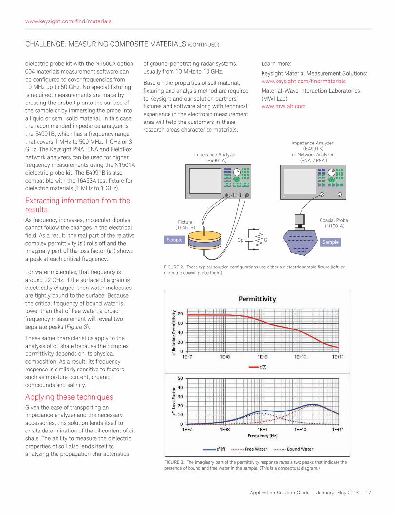
GCp
Fixture(16451B)
Sample Sample
Impedance Analyzer(E4990A)
Coaxial Probe(N1501A)
Impedance Analyzer(E4991B)
or Network Analyzer(ENA / PNA )
FIGURE 2. These typical solution conigurations use either a dielectric sample ixture (left) or dielectric coaxial probe (right).
FIGURE 3. The imaginary part of the permittivity response reveals two peaks that indicate the
presence of bound and free water in the sample. (This is a conceptual diagram.)
www.keysight.com/ind/materials
18 | Application Solution Guide | January–May 2016
Impedance Analyzers
See the real characteristics of complex materials and devices
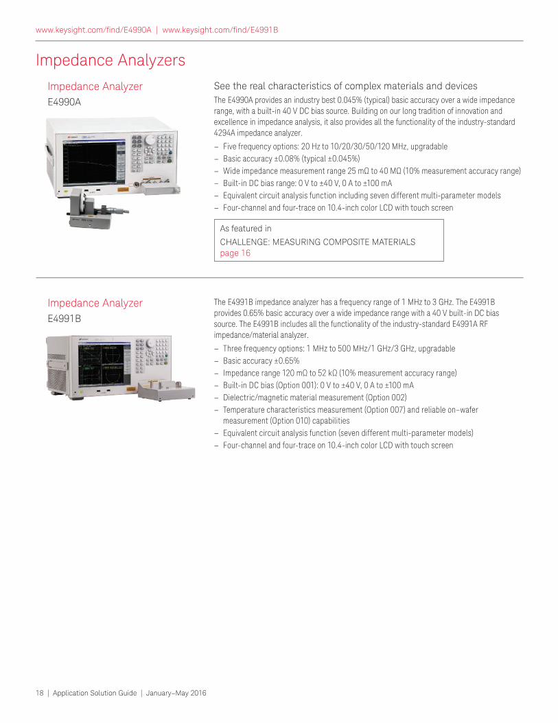
The E4990A provides an industry best 0.045% (typical) basic accuracy over a wide impedance range, with a built-in 40 V DC bias source. Building on our long tradition of innovation and excellence in impedance analysis, it also provides all the functionality of the industry-standard 4294A impedance analyzer.
– Five frequency options: 20 Hz to 10/20/30/50/120 MHz, upgradable
– Basic accuracy ±0.08% (typical ±0.045%)
– Wide impedance measurement range 25 mΩ to 40 MΩ (10% measurement accuracy range) – Built-in DC bias range: 0 V to ±40 V, 0 A to ±100 mA
– Equivalent circuit analysis function including seven different multi-parameter models
– Four-channel and four-trace on 10.4-inch color LCD with touch screen
Impedance Analyzer
E4990A
The E4991B impedance analyzer has a frequency range of 1 MHz to 3 GHz. The E4991B provides 0.65% basic accuracy over a wide impedance range with a 40 V built-in DC bias source. The E4991B includes all the functionality of the industry-standard E4991A RF impedance/material analyzer.
– Three frequency options: 1 MHz to 500 MHz/1 GHz/3 GHz, upgradable
– Basic accuracy ±0.65%
– Impedance range 120 mΩ to 52 kΩ (10% measurement accuracy range) – Built-in DC bias (Option 001): 0 V to ±40 V, 0 A to ±100 mA
– Dielectric/magnetic material measurement (Option 002)
– Temperature characteristics measurement (Option 007) and reliable on–wafer measurement (Option 010) capabilities
– Equivalent circuit analysis function (seven different multi-parameter models)
– Four-channel and four-trace on 10.4-inch color LCD with touch screen
Impedance Analyzer
E4991B
As featured in
CHALLENGE: MEASURING COMPOSITE MATERIALS page 16
www.keysight.com/ind/E4990A | www.keysight.com/ind/E4991B
Application Solution Guide | January–May 2016 | 19
Bit Error Ratio Testers
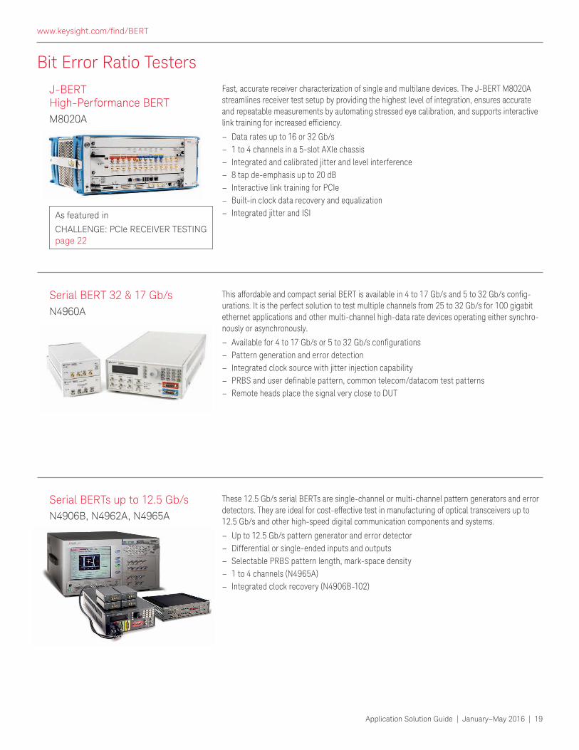
Fast, accurate receiver characterization of single and multilane devices. The J-BERT M8020A streamlines receiver test setup by providing the highest level of integration, ensures accurate and repeatable measurements by automating stressed eye calibration, and supports interactive link training for increased eficiency.
– Data rates up to 16 or 32 Gb/s
– 1 to 4 channels in a 5-slot AXIe chassis
– Integrated and calibrated jitter and level interference
– 8 tap de-emphasis up to 20 dB
– Interactive link training for PCIe
– Built-in clock data recovery and equalization
– Integrated jitter and ISI
J-BERT High-Performance BERT
M8020A
This affordable and compact serial BERT is available in 4 to 17 Gb/s and 5 to 32 Gb/s conig-urations. It is the perfect solution to test multiple channels from 25 to 32 Gb/s for 100 gigabit ethernet applications and other multi-channel high-data rate devices operating either synchro-nously or asynchronously.
– Available for 4 to 17 Gb/s or 5 to 32 Gb/s conigurations – Pattern generation and error detection
– Integrated clock source with jitter injection capability
– PRBS and user deinable pattern, common telecom/datacom test patterns – Remote heads place the signal very close to DUT
Serial BERT 32 & 17 Gb/s
N4960A
These 12.5 Gb/s serial BERTs are single-channel or multi-channel pattern generators and error detectors. They are ideal for cost-effective test in manufacturing of optical transceivers up to 12.5 Gb/s and other high-speed digital communication components and systems.
– Up to 12.5 Gb/s pattern generator and error detector
– Differential or single-ended inputs and outputs
– Selectable PRBS pattern length, mark-space density
– 1 to 4 channels (N4965A)
– Integrated clock recovery (N4906B-102)
Serial BERTs up to 12.5 Gb/s
N4906B, N4962A, N4965A
As featured in
CHALLENGE: PCIe RECEIVER TESTING page 22
www.keysight.com/ind/BERT
20 | Application Solution Guide | January–May 2016
Network Analyzers
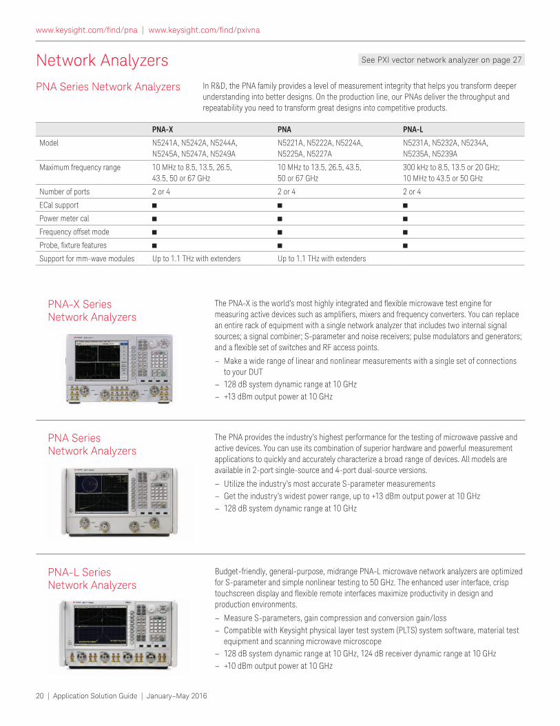
The PNA-X is the world’s most highly integrated and lexible microwave test engine for measuring active devices such as ampliiers, mixers and frequency converters. You can replace an entire rack of equipment with a single network analyzer that includes two internal signal sources; a signal combiner; S-parameter and noise receivers; pulse modulators and generators; and a lexible set of switches and RF access points.
– Make a wide range of linear and nonlinear measurements with a single set of connections to your DUT
– 128 dB system dynamic range at 10 GHz
– +13 dBm output power at 10 GHz
PNA-X Series Network Analyzers
The PNA provides the industry’s highest performance for the testing of microwave passive and active devices. You can use its combination of superior hardware and powerful measurement applications to quickly and accurately characterize a broad range of devices. All models are available in 2-port single-source and 4-port dual-source versions.
– Utilize the industry’s most accurate S-parameter measurements
– Get the industry’s widest power range, up to +13 dBm output power at 10 GHz
– 128 dB system dynamic range at 10 GHz
PNA Series Network Analyzers
Budget-friendly, general-purpose, midrange PNA-L microwave network analyzers are optimized for S-parameter and simple nonlinear testing to 50 GHz. The enhanced user interface, crisp touchscreen display and lexible remote interfaces maximize productivity in design and production environments.
– Measure S-parameters, gain compression and conversion gain/loss
– Compatible with Keysight physical layer test system (PLTS) system software, material test equipment and scanning microwave microscope
– 128 dB system dynamic range at 10 GHz, 124 dB receiver dynamic range at 10 GHz
– +10 dBm output power at 10 GHz
PNA-L Series Network Analyzers
PNA-X PNA PNA-L
Model N5241A, N5242A, N5244A,
N5245A, N5247A, N5249A
N5221A, N5222A, N5224A,
N5225A, N5227A
N5231A, N5232A, N5234A,
N5235A, N5239A
Maximum frequency range 10 MHz to 8.5, 13.5, 26.5,
43.5, 50 or 67 GHz
10 MHz to 13.5, 26.5, 43.5,
50 or 67 GHz
300 kHz to 8.5, 13.5 or 20 GHz;
10 MHz to 43.5 or 50 GHz
Number of ports 2 or 4 2 or 4 2 or 4
ECal support
Power meter cal
Frequency offset mode
Probe, ixture features
Support for mm-wave modules Up to 1.1 THz with extenders Up to 1.1 THz with extenders
In R&D, the PNA family provides a level of measurement integrity that helps you transform deeper understanding into better designs. On the production line, our PNAs deliver the throughput and repeatability you need to transform great designs into competitive products.
PNA Series Network Analyzers
See PXI vector network analyzer on page 27
www.keysight.com/ind/pna | www.keysight.com/ind/pxivna
Application Solution Guide | January–May 2016 | 21
Network Analyzers
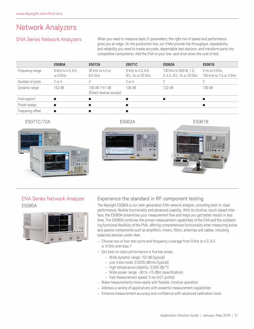
Experience the standard in RF component testingThe Keysight E5080A is our next-generation ENA network analyzer, providing best-in-class performance, lexible functionality and advanced usability. With its intuitive, touch-based inter-face, the E5080A streamlines your measurement low and helps you get better results in less time. The E5080A combines the proven measurement capabilities of the ENA and the outstand-ing functional lexibility of the PNA, offering comprehensive functionality when measuring active and passive components such as ampliiers, mixers, ilters, antennas and cables, including balanced devices-under-test.
– Choose two or four test ports and frequency coverage from 9 kHz to 4.5, 6.5 or 9 GHz with bias-T
– Get best-in-class performance in ive key areas: – Wide dynamic range: 152 dB (typical) – Low trace noise: 0.0005 dBrms (typical) – High temperature stability: 0.005 dB/°C – Wide power range: -90 to +15 dBm (speciication) – Fast measurement speed: 3 ms (401 points)
– Make measurements more easily with lexible, intuitive operation – Address a variety of applications with powerful measurement capabilities
– Enhance measurement accuracy and conidence with advanced calibration tools
ENA Series Network Analyzer
E5080A
E5071C/72A E5063A E5061B
ENA Series Network Analyzers When you need to measure basic S-parameters, the right mix of speed and performance gives you an edge. On the production line, our ENAs provide the throughput, repeatability and reliability you need to create accurate, dependable test stations—and transform parts into competitive components. Add the ENA to your line—and drive down the cost of test.
E5080A E5072A E5071C E5063A E5061B
Frequency range 9 kHz to 4.5, 6.5
or 9 GHz
30 kHz to 4.5 or
8.5 GHz
9 kHz to 4.5, 6.5,
8.5, 14 or 20 GHz
100 kHz to 500 M, 1.5,
3, 4.5, 8.5, 14 or 20 GHz
5 Hz to 3 GHz,
100 kHz to 1.5 or 3 GHz
Number of ports 2 or 4 2 2 or 4 2 2
Dynamic range 152 dB 130 dB /151 dB
(Direct receiver access)
130 dB 122 dB 130 dB
Ecal support
Power sweep
Frequency offset
www.keysight.com/ind/ena
22 | Application Solution Guide | January–May 2016
Thoroughly Characterizing and Validating PCI Express Receiver Designs
The graphics and video subsystems inside
today’s PCs rely on the PCI Express® (PCIe)
high-speed serial bus to handle massive
data transfers. For hardware developers, testing PCIe receiver performance has
become especially dificult because fast signals passing through printed-circuit
traces deteriorate so much, that eye diagrams measured at the receiver input
may be completely closed. This poses
new problems in the process of ensuring
interoperability, backward compatibility and compliance with the latest version of
the PCIe standard. The answer is a solution
set that supports thorough characterization
and validation of the parametric and
protocol aspects of a design.
A key test challenge: Characterizing receiver performanceIn any serial bus, higher data rates often lead to issues with signal integrity—
relections, crosstalk, and more—that cause signal degradation and create timing
problems. For example, a shorter clock cycle means a smaller jitter budget, which makes it much more dificult to reduce jitter in a design.
Focusing on PCIe, every design can be separated into three layers: physical, data-link and transaction. At the physical
or PHY layer, it’s necessary to perform interconnect, transmitter and receiver testing. Among these, receiver testing at high data rates is the most challenging
process.
In a digital transmission system, the receiver must extract the digital content
from its input signal while maintaining a
very low bit error ratio (BER). The more
robust a receiver design, the greater its ability to tolerate distorted signals and
make the correct bit decisions.
Making quick, accurate jitter tolerance testsTo qualify receiver performance, PCIe uses a jitter tolerance test based on a calibrated
stress signal. Fully characterizing jitter
tolerance requires a pattern generator that
can create signals that put the receiver
into loop-back mode and also produce
a reference clock with spread-spectrum
capability. The generator must also create
calibrated, compliant jitter injection and de-emphasis to emulate receiver stress
conditions.
The extent to which the pattern generator
allows control of these attributes is
essential to determining measurement
accuracy. Greater precision enables better
understanding of receiver performance.
The Keysight J-BERT M8020A and
J-BERT N4903B offer fully integrated and
calibrated precision jitter sources. Both
CHALLENGE: PCIe RECEIVER TESTING
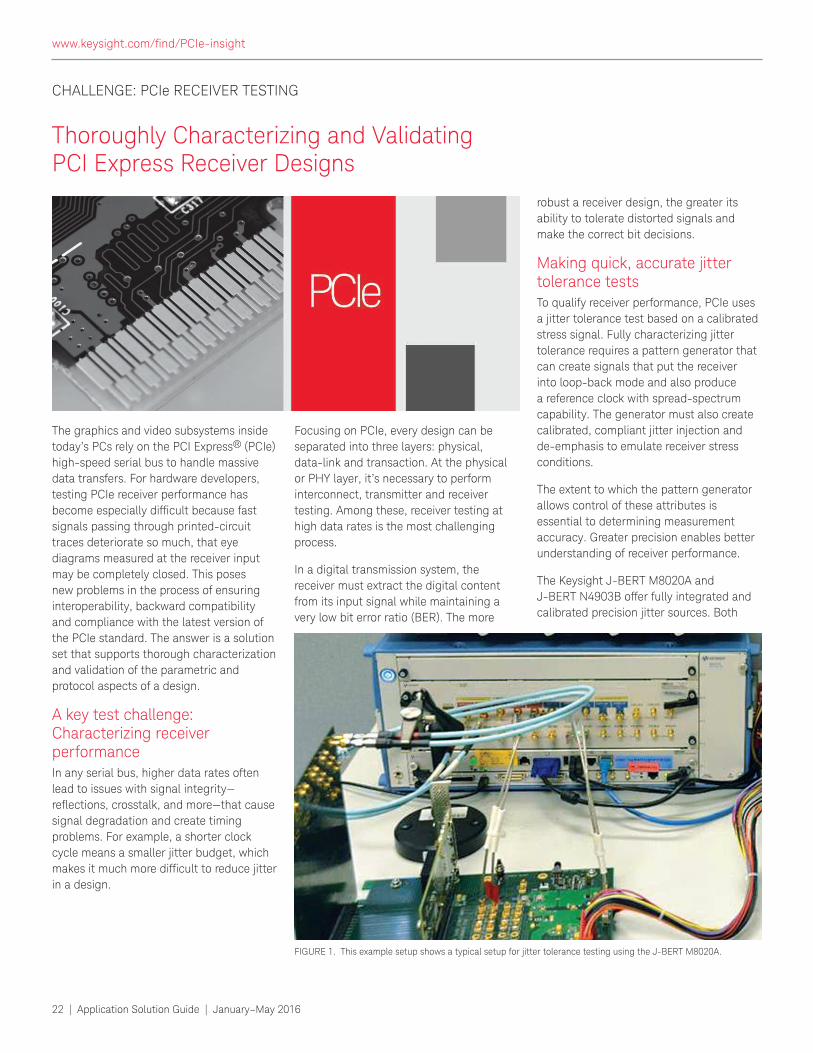
FIGURE 1. This example setup shows a typical setup for jitter tolerance testing using the J-BERT M8020A.
www.keysight.com/ind/PCIe-insight
Application Solution Guide | January–May 2016 | 23
models provide quick, authentic, worst-case jitter, and amplitude signals. These include random, sinusoidal and periodic jitter—plus inter-symbol interference (ISI)—
to emulate motherboard conditions.
Built-in test routines enable rapid testing
of a receiver’s jitter tolerance (Figure 1)
and the M8020A also has the ability to be
used for link equalization testing. To further
characterize a receiver, both J-BERT models can emulate a transmitter with de-
emphasized PCIe signals. This capability
is integrated into the J-BERT M8020A, simplifying test setup; the J-BERT N4903B
requires the addition of the N4916B de-
emphasis converter.
Simplifying complex tasksThe versatility of PCIe is apparent in multi-
lane designs. The good news: additional
lanes increase throughput. The bad:
receiver design is more complicated and
debug becomes more dificult.
To facilitate multi-lane receiver testing, the J-BERT M8020A is a modular platform
that can be conigured with multiple data generators and data analyzers. With
the N5990A software (Figure 2), it also supports automated receiver testing and
complete transmitter/receiver compliance
testing. The software can control the
J-BERT M8020A and J-BERT N4903B as
well as Ininiium oscilloscopes and other Keysight solutions.
Applying the J-BERT M8020ATo date, most solutions for receiver test require additional instruments to complete
the stressor set offered by the BERT. This
includes the J-BERT N4903B.
In contrast, the J-BERT M8020A offers built-in common-mode and differential-
mode sinusoidal interference (CM-SI and
DM-SI, respectively). This eliminates the need for additional non-ISI stressors.
The J-BERT M8020A also has an integrated
PCIe-compliant reference clock multiplier
that can generate the necessary clock
for the BERT from the system’s 100 MHz
reference clock. Because the multiplier
uses a phase-locked loop (PLL) with
enough bandwidth to transfer spread-
spectrum clock (SSC), the J-BERT M8020A can test systems with SSC turned on.
The M8041A BERT module offers data
ranges up to 8.5 Gb/s or 16.2 Gb/s. The
16.2 Gb/s version supports testing of
receivers at all four transfer rates.
Realizing your best designIn digital standards, every new version puts unfamiliar risks in the design path.
Keysight sees this irsthand when designing new products and when working with
customers. The Keysight solution set for
high-speed digital test is a combination
of software, instrumentation and broad expertise built on early and on-going
involvement with industry experts. By
capturing these capabilities in the high-
performance J-BERT M8020A, Keysight enables developers to characterize, validate and master their PCIe receiver designs.
For more information regarding
Keysight’s PCIe solutions, visit www.keysight.com/ind/PCIe-insight
Keysight offers solutions to meet your
needs in the electrical physical layer, protocol layer, and functional test . See an overview of these solutions in
the following pages.
CHALLENGE: PCIe RECEIVER TESTING (CONTINUED)
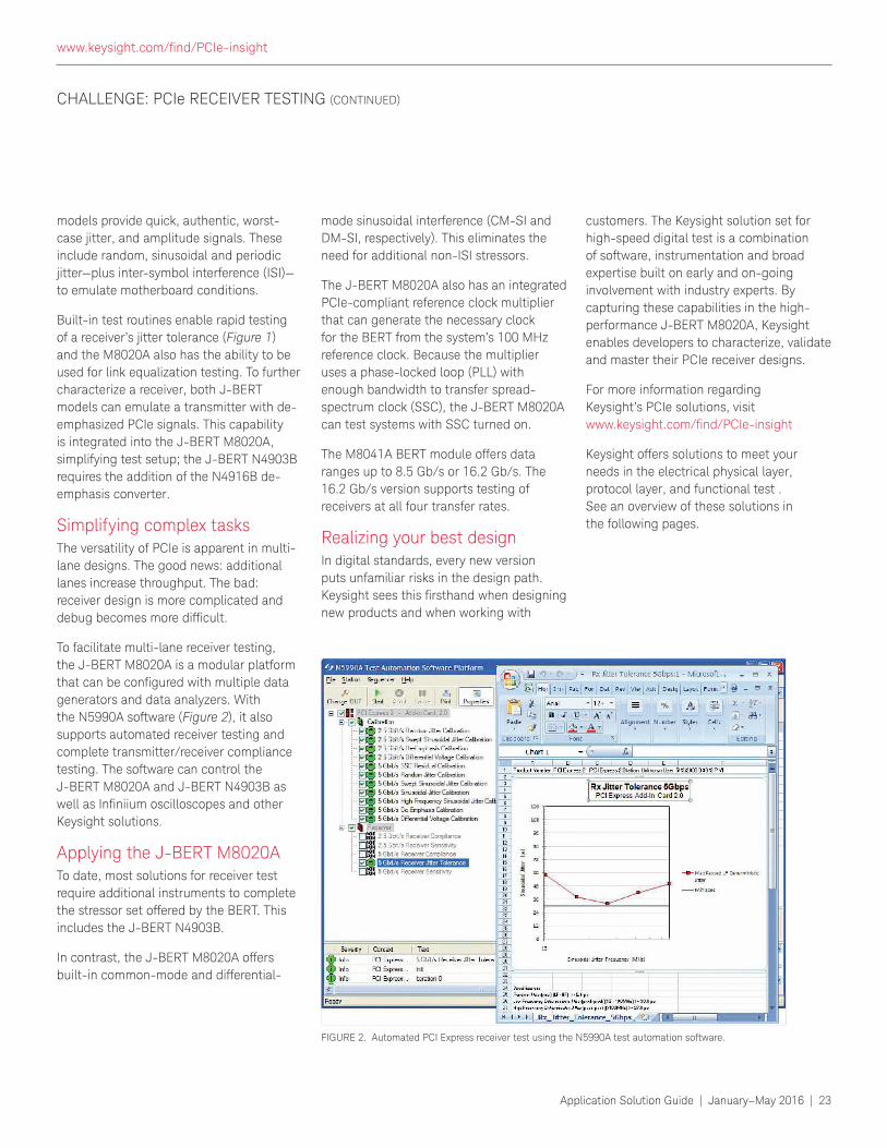
FIGURE 2. Automated PCI Express receiver test using the N5990A test automation software.
www.keysight.com/ind/PCIe-insight
24 | Application Solution Guide | January–May 2016
Solutions for PCIe – Receiver and Transmitter Test
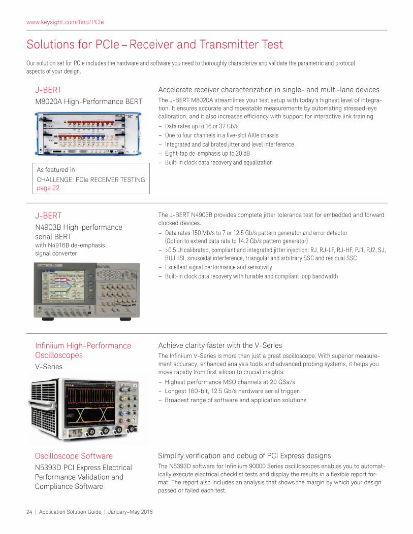
Accelerate receiver characterization in single- and multi-lane devices
The J-BERT M8020A streamlines your test setup with today’s highest level of integra-
tion. It ensures accurate and repeatable measurements by automating stressed-eye
calibration, and it also increases eficiency with support for interactive link training.
– Data rates up to 16 or 32 Gb/s
– One to four channels in a ive-slot AXIe chassis – Integrated and calibrated jitter and level interference
– Eight-tap de-emphasis up to 20 dB
– Built-in clock data recovery and equalization
J-BERT
M8020A High-Performance BERT
The J-BERT N4903B provides complete jitter tolerance test for embedded and forward
clocked devices.
– Data rates 150 Mb/s to 7 or 12.5 Gb/s pattern generator and error detector (Option to extend data rate to 14.2 Gb/s pattern generator)
– >0.5 UI calibrated, compliant and integrated jitter injection: RJ, RJ-LF, RJ-HF, PJ1, PJ2, SJ, BUJ, ISI, sinusoidal interference, triangular and arbitrary SSC and residual SSC
– Excellent signal performance and sensitivity
– Built-in clock data recovery with tunable and compliant loop bandwidth
J-BERT
N4903B High-performance
serial BERTwith N4916B de-emphasis
signal converter
Simplify veriication and debug of PCI Express designsThe N5393D software for Ininiium 90000 Series oscilloscopes enables you to automat-ically execute electrical checklist tests and display the results in a lexible report for-mat. The report also includes an analysis that shows the margin by which your design
passed or failed each test.
Oscilloscope Software
N5393D PCI Express Electrical
Performance Validation and
Compliance Software
Achieve clarity faster with the V-Series
The Ininiium V-Series is more than just a great oscilloscope. With superior measure-
ment accuracy, enhanced analysis tools and advanced probing systems, it helps you move rapidly from irst silicon to crucial insights.
– Highest performance MSO channels at 20 GSa/s
– Longest 160-bit, 12.5 Gb/s hardware serial trigger
– Broadest range of software and application solutions
Ininiium High-Performance Oscilloscopes
V-Series
Our solution set for PCIe includes the hardware and software you need to thoroughly characterize and validate the parametric and protocol aspects of your design.
As featured in
CHALLENGE: PCIe RECEIVER TESTING page 22
www.keysight.com/ind/PCIe
Application Solution Guide | January–May 2016 | 25
Solutions for PCIe – Interconnect Test
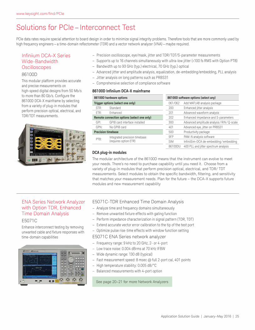
– Precision oscilloscope, eye/mask, jitter and TDR/TDT/S-parameter measurements
– Supports up to 16 channels simultaneously with ultra-low jitter (<100 fs RMS with Option PTB)
– Bandwidth up to 93 GHz (typ.) electrical, 70 GHz (typ.) optical
– Advanced jitter and amplitude analysis, equalization, de-embedding/embedding, PLL analysis
– Jitter analysis on long patterns such as PRBS31
– Comprehensive selection of compliance software
The modular architecture of the 86100D means that the instrument can evolve to meet
your needs. There’s no need to purchase capability until you need it. Choose from a
variety of plug-in modules that perform precision optical, electrical, and TDR/ TDT measurements. Select modules to obtain the speciic bandwidth, iltering, and sensitivity that matches your measurement needs. Plan for the future – the DCA-X supports future
modules and new measurement capability
E5071C-TDR Enhanced Time Domain Analysis
– Analyze time and frequency domains simultaneously
– Remove unwanted ixture effects with gating function – Perform impedance characterization in signal pattern (TDR, TDT)
– Extend accurate vector error calibration to the tip of the test port
– Optimize pulse rise-time effects with window function setting
E5071C ENA Series network analyzer
– Frequency range: 9 kHz to 20 GHz, 2- or 4-port
– Low trace noise: 0.004 dBrms at 70 kHz IFBW
– Wide dynamic range: 130 dB (typical)
– Fast measurement speed: 8 msec @ full 2-port cal, 401 points
– High temperature stability: 0.005 dB/°C
– Balanced measurements with 4-port option
Ininiium DCA-X Series Wide-Bandwidth Oscilloscopes
86100D
This modular platform provides accurate and precise measurements on high-speed digital designs from 50 Mb/s to more than 80 Gb/s. Conigure the 86100D DCA-X mainframe by selecting from a variety of plug-in modules that perform precision optical, electrical, and TDR/TDT measurements.
ENA Series Network Analyzer with Option TDR, Enhanced Time Domain Analysis
E5071C
Enhance interconnect testing by removing unwanted cable and ixture responses with time-domain capabilities
See page 20–21 for more Network Analyzers
PCIe data rates require special attention to board design in order to minimize signal integrity problems. Therefore tools that are more commonly used by high frequency engineers — a time-domain relectometer (TDR) and a vector network analyzer (VNA) — maybe required.
86100D software options (select any)
061/062 Add MATLAB analysis package
200 Enhanced jitter analysis
201 Advanced waveform analysis
202 Enhanced impedance and S-parameters
300 Advanced amplitude analysis / RIN / Q-scale
401 Advanced eye, jitter on PRBS31
500 Productivity package
9FP PAM-N analysis software
SIM IniniiSim-DCA de-embedding / embedding86100DU 400 PLL and jitter spectrum analysis
86100D Ininiium DCA-X mainframe
DCA plug-in modules
86100D hardware options
Trigger options (select one only)
STR: Standard
ETR: Enhanced
Remote connection options (select one only)
GPI: GPIB card interface installed
GPN: No GPIB card
Precision timebase
PTB:Integrated precision timebase (requires option ETR)
www.keysight.com/ind/PCIe
26 | Application Solution Guide | January–May 2016
PXI and AXIe Modular Instruments
Keysight’s growing range of trusted PXI and AXIe modular instruments extends its measurement expertise to PXIe vector network analyzers, vector sig-nal analyzers, vector signal generators and AXIe multi-channel digitizers, arbitrary waveform generators and logic analyzers. Strengthened by Keysight’s world-class software applications, support and services, modular instruments provide trusted measurements from DC to microwave domains.
PXI and AXIe Reference SolutionsReference solutions are a combination of hardware, software and measurement expertise enabling users to more rapidly evaluate a test coniguration for a speciic test application. Two examples are shown, below.
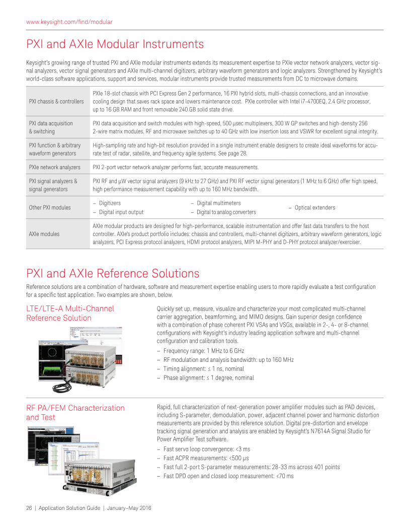
RF PA/FEM Characterization and Test
LTE/LTE-A Multi-Channel Reference Solution
Rapid, full characterization of next-generation power ampliier modules such as PAD devices, including S-parameter, demodulation, power, adjacent channel power and harmonic distortion measurements are provided by this reference solution. Digital pre-distortion and envelope tracking signal generation and analysis are enabled by Keysight’s N7614A Signal Studio for Power Ampliier Test software.
– Fast servo loop convergence: <3 ms
– Fast ACPR measurements: <500 µs
– Fast full 2-port S-parameter measurements: 28-33 ms across 401 points
– Fast DPD open and closed loop measurement: <70 ms
Quickly set up, measure, visualize and characterize your most complicated multi-channel carrier aggregation, beamforming, and MIMO designs. Gain superior design conidence with a combination of phase coherent PXI VSAs and VSGs, available in 2-, 4- or 8-channel conigurations with Keysight’s industry leading application software and multi-channel coniguration and calibration tools.
– Frequency range: 1 MHz to 6 GHz
– RF modulation and analysis bandwidth: up to 160 MHz
– Timing alignment: ≤ 1 ns, nominal – Phase alignment: ≤ 1 degree, nominal
PXI chassis & controllers
PXIe 18-slot chassis with PCI Express Gen 2 performance, 16 PXI hybrid slots, multi-chassis connections, and an innovative
cooling design that saves rack space and lowers maintenance cost. PXIe controller with Intel i7-4700EQ, 2.4 GHz processor,
up to 16 GB RAM and front removable 240 GB solid state drive.
PXI data acquisition
& switching
PXI data acquisition and switch modules with high-speed, 500 μsec multiplexers, 300 W GP switches and high-density 256 2-wire matrix modules. RF and microwave switches up to 40 GHz with low insertion loss and VSWR for excellent signal integrity.
PXI function & arbitrary
waveform generators
High-sampling rate and high-bit resolution provided in a single instrument enable designers to create ideal waveforms for accu-
rate test of radar, satellite, and frequency agile systems. See page 28.
PXIe network analyzers PXI 2-port vector network analyzer performs fast, accurate measurements.
PXI signal analyzers &
signal generators
PXI RF and µW vector signal analyzers (9 kHz to 27 GHz) and PXI RF vector signal generators (1 MHz to 6 GHz) offer high speed,
high performance measurement capability with up to 160 MHz bandwidth.
Other PXI modules – Digitizers
– Digital input output
– Digital multimeters
– Digital to analog converters – Optical extenders
AXIe modules
AXIe modular products are designed for high-performance, scalable instrumentation and offer fast data transfers to the host
controller. AXIe’s product portfolio includes: chassis and controllers, multi-channel digitizers, arbitrary waveform generators, logic
analyzers, PCI Express protocol analyzers, HDMI protocol analyzers, MIPI M-PHY and D-PHY protocol analyzer/exerciser.
www.keysight.com/ind/modular
Application Solution Guide | January–May 2016 | 27
PXI and AXIe Modular Instruments
Experience high speed digital test capabilities at a whole new level.
High speed 16-channel digital stimulus response for fast and lexible digital pattern generation. The powerful pattern cyclizer technology enables on-the-ly pattern cre-
ation for single site, or up to four independent multi-sites, with high-voltage channels and open drain pins for simultaneous device test.
– Emulation of serial and parallel digital device interfaces
– Precise vector time with a powerful combination of waveform tables and up to 250 ns stim-ulus/response delay compensation with 25 ps programming resolution
– Industry-leading 1 ns-per-bit edge placement resolution giving engineers the ability to validate device design with greater accuracy
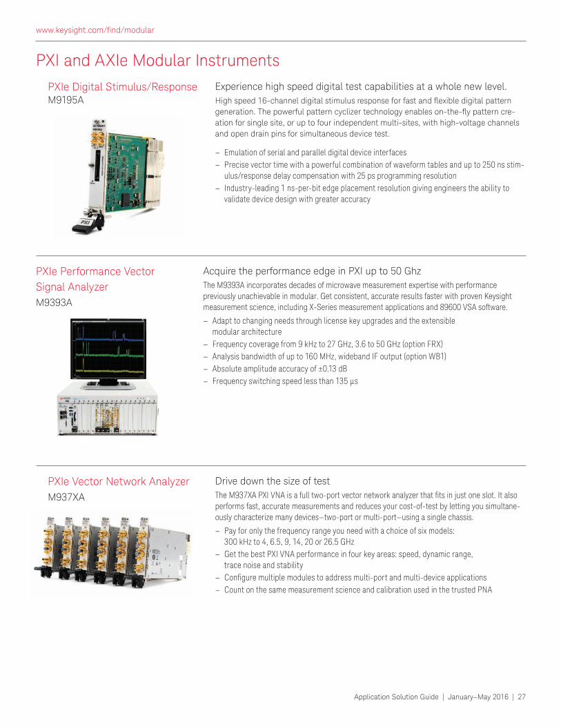
Drive down the size of test
The M937XA PXI VNA is a full two-port vector network analyzer that its in just one slot. It also performs fast, accurate measurements and reduces your cost-of-test by letting you simultane-ously characterize many devices—two-port or multi-port—using a single chassis.
– Pay for only the frequency range you need with a choice of six models: 300 kHz to 4, 6.5, 9, 14, 20 or 26.5 GHz
– Get the best PXI VNA performance in four key areas: speed, dynamic range, trace noise and stability
– Conigure multiple modules to address multi-port and multi-device applications – Count on the same measurement science and calibration used in the trusted PNA
PXIe Digital Stimulus/Response M9195A
PXIe Vector Network Analyzer
M937XA
Acquire the performance edge in PXI up to 50 Ghz
The M9393A incorporates decades of microwave measurement expertise with performance previously unachievable in modular. Get consistent, accurate results faster with proven Keysight measurement science, including X-Series measurement applications and 89600 VSA software.
– Adapt to changing needs through license key upgrades and the extensible modular architecture
– Frequency coverage from 9 kHz to 27 GHz, 3.6 to 50 GHz (option FRX)
– Analysis bandwidth of up to 160 MHz, wideband IF output (option WB1)
– Absolute amplitude accuracy of ±0.13 dB
– Frequency switching speed less than 135 μs
PXIe Performance Vector
Signal Analyzer
M9393A
www.keysight.com/ind/modular

US +1 800 829-4444 Canada +1 877 894-4414
www.keysight.com
This information is subject to change without notice.
© Keysight Technologies, 2016Published in USA, January 1, 20165992-0114ENUC
www.keysight.com
Technical data and pricing subject to change
without notice.
PCIe® and PCI-SIG® and the PCI SIG design
marks are US registered trademarks and/or
service marks of PCI-SIG.
Bluetooth and the Bluetooth logos are trade-
marks owned by Bluetooth SIG, Inc., U.S.A. and licensed to Keysight Technologies, Inc.
cdma2000 is a US registered certiication mark of the Telecommuncations Industry Association.
WiMAX is a US trademark of the WiMAX forum.
With TestEquity and Keysight you get the best of both
worlds: Keysight’s measurement expertise and product
breadth, combined with speed, convenience, and
same-day shipping from TestEquity.
• Fast delivery from stock
• Volume discounts, flexible payment terms from
TestEquity
• Our consultative selling process gives you a
dedicated support team to help you make the best
decision for your unique situation
• Ongoing support — before, during and after your
purchase
Contact TestEquity at:
805.498.9933
www.testequity.com/manufacturer/Keysight/
TestEquity is proud to be an authorized
distributor of Keysight bench instruments.
Authorized Distributor
www.keysight.com
For more information on Keysight Technologies’
products, applications or services, please con-
tact your local Keysight ofice.
www.keysight.com/ind/contactus
Microlease is Company of the Year in Test & Measurement
Rental/Leasing Services for 3rd Consecutive Year
- Frost & Sullivan
As Keysight’s only Authorized Distributor who’s also a Premier
Rental Partner, Microlease makes acquiring Keysight equipment
EASY, whether it’s new, Certiied-Pre-Owned or for rent.
1. Large Keysight Inventory In stock, ready to ship.
2. Flexible Rental Options We’ll build a rental solution the
way you want it.
3. No Capex? No Problem! Ask us about our creative
inancing and leasing payment options.
Award-Winning
Rental Solutions
www.microlease.com/us/keysight
[email protected] | 888.895.6456
Total
Flexibility
Immediate
Availabiity
Next-Day
Delivery