keynote at 23rd international display workshop
TRANSCRIPT

BREAKING THE BARRIERS TO TRUE AUGMENTED REALITY
CHRISTIAN SANDOR [email protected]
KEYNOTE AT 23RD INTERNATIONAL DISPLAY WORKSHOP FUKUOKA, JAPAN 7 DECEMBER 2016

BURNAR: FEEL THE HEAT
MATT SWOBODA, THANH NGUYEN, ULRICH ECK, GERHARD REITMAYR, STEFAN HAUSWIESNER, RENE RANFTL, AND CHRISTIAN SANDOR. DEMO AT IEEE INTERNATIONAL SYMPOSIUM ON MIXED AND AUGMENTED REALITY, BASEL, SWITZERLAND, OCTOBER 2011. BEST DEMO AWARD


BURNAR: INVOLUNTARY HEAT SENSATIONS IN AR
PETER WEIR, CHRISTIAN SANDOR, MATT SWOBODA, THANH NGUYEN, ULRICH ECK, GERHARD REITMAYR, AND ARINDAM DEY. PROCEEDINGS OF THE IEEE VIRTUAL REALITY CONFERENCE, PAGES 43–46, ORLANDO, FL, USA, MARCH 2013.

WORKSHOP AT NAIST, AUGUST 2014
ARXIV E-PRINTS, ARXIV:1512.05471 [CS.HC], 13 PAGES HTTP://ARXIV.ORG/ABS/1512.05471
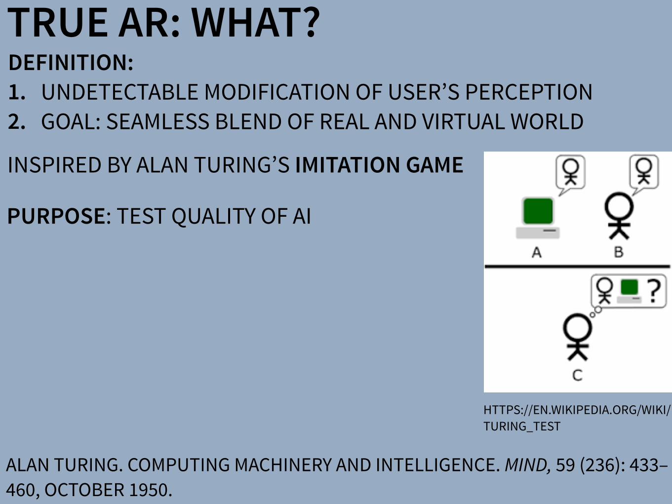
DEFINITION: 1. UNDETECTABLE MODIFICATION OF USER’S PERCEPTION 2. GOAL: SEAMLESS BLEND OF REAL AND VIRTUAL WORLD
TRUE AR: WHAT?
HTTPS://EN.WIKIPEDIA.ORG/WIKI/TURING_TEST
ALAN TURING. COMPUTING MACHINERY AND INTELLIGENCE. MIND, 59 (236): 433–460, OCTOBER 1950.
INSPIRED BY ALAN TURING’S IMITATION GAME
PURPOSE: TEST QUALITY OF AI
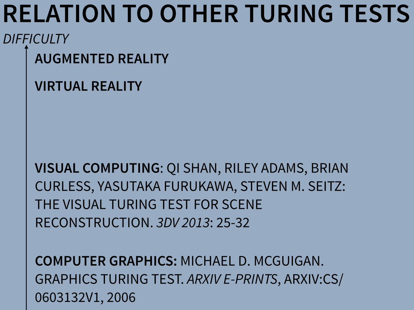
RELATION TO OTHER TURING TESTS
COMPUTER GRAPHICS: MICHAEL D. MCGUIGAN. GRAPHICS TURING TEST. ARXIV E-PRINTS, ARXIV:CS/0603132V1, 2006
VISUAL COMPUTING: QI SHAN, RILEY ADAMS, BRIAN CURLESS, YASUTAKA FURUKAWA, STEVEN M. SEITZ: THE VISUAL TURING TEST FOR SCENE RECONSTRUCTION. 3DV 2013: 25-32
VIRTUAL REALITY
AUGMENTED REALITYDIFFICULTY

TRUE AR: WHY?TRAINING: SPORTS & SKILLS AMUSEMENT: INTERACTIVE STORIES SCIENCE: PSYCHOLOGY & NEUROSCIENCE LAW: FORENSICS & LOGISTICS OF CRIME SCENE
STAR TREK HOLODECK. HTTPS://EN.WIKIPEDIA.ORG/WIKI/HOLODECK
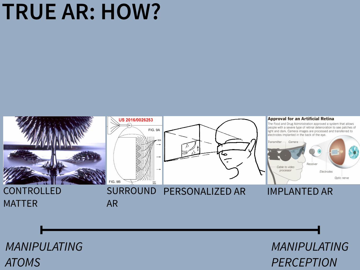
TRUE AR: HOW?
MANIPULATING ATOMS
MANIPULATING PERCEPTION
CONTROLLED MATTER
PERSONALIZED AR IMPLANTED ARSURROUND AR
There have been a number of shape displays based on pin architecture. The FEELEX project [14] was one of the early attempts to design combined shapes and computer graphics displays that can be explored by touch. FEELEX consisted of several mechanical pistons actuated by motors and cov-ered by a soft silicon surface. The images were projected onto its surface and synchronized with the movement of the pistons, creating simple shapes.
Lumen [32] is a low resolution, 13 by 13-pixel, bit-map display where each pixel can also physically move up and down (Figure 4). The resulting display can present both 2D graphic images and moving physical shapes that can be observed, touched, and felt with the hands. The 2D position sensor built into the surface of Lumen allows users to input commands and manipulate shapes with their hands.
Other related project are PopUp and Glowbits devices [18, 33]. PopUp consists of an array of rods that can be moved up and down using shape memory alloy actuators. The PopUp, however, does not have a visual and interactive component. Glowbits by Daniel Hirschmann (Figure 3) is a 2D array of rods with attached LEDs; the motorized rods can move up and down and LEDs can change their colors.
Discussion We have overviews a number of reasons why actuation can be used in user interfaces. We summarize them in Table 1.
Applications Examples
Aesthetics Automata, ambient displays, shape displays
Information communication
Ambient displays, haptic displays, shape displays
Mechanical work Robots
Controls—data consistency
Actuated tangibles
People-to-people communication
Haptic displays
Table 1: Applications of actuation in user interfaces
Most of the actual devices potentially span more then one application area and it seems that there is a lot of room for innovation and using some of the actuated interfaces in new application areas. For examples, robots could be used for information communication and ambient displays could be used for people-to-people communication.
Future research in actuated interfaces might attempt to sys-tematically investigate applications of actuated devices for various applications, some if which are perhaps not listed above. In the next section we provide analysis of shape dis-plays and there possible applications.
Figure 3: Shape displays (from top): Protrude, Flow,
Snoil, Aegis Hyposurface, Glowbits
2.1 Runtime Environments for User Interfaces in Ubiquitous Augmented Reality
Figure 2.7: Hand-fixed reference frame: Augmentations move with the hand of the user. Thisexample shows a user discussing a virtual map with another user. To observe themap from di↵erent angles, he can pick it up from the body-fixed toolchest aroundhis belt and put it in his hand.
Figure 2.8: Head-fixed reference frame: Augmentations move with the head gaze of the user.The example shows a map of the environment that supports a navigational task.
A Software Toolkit and Authoring Tools for User Interfaces in Ubiquitous Augmented Reality 21

There have been a number of shape displays based on pin architecture. The FEELEX project [14] was one of the early attempts to design combined shapes and computer graphics displays that can be explored by touch. FEELEX consisted of several mechanical pistons actuated by motors and cov-ered by a soft silicon surface. The images were projected onto its surface and synchronized with the movement of the pistons, creating simple shapes.
Lumen [32] is a low resolution, 13 by 13-pixel, bit-map display where each pixel can also physically move up and down (Figure 4). The resulting display can present both 2D graphic images and moving physical shapes that can be observed, touched, and felt with the hands. The 2D position sensor built into the surface of Lumen allows users to input commands and manipulate shapes with their hands.
Other related project are PopUp and Glowbits devices [18, 33]. PopUp consists of an array of rods that can be moved up and down using shape memory alloy actuators. The PopUp, however, does not have a visual and interactive component. Glowbits by Daniel Hirschmann (Figure 3) is a 2D array of rods with attached LEDs; the motorized rods can move up and down and LEDs can change their colors.
Discussion We have overviews a number of reasons why actuation can be used in user interfaces. We summarize them in Table 1.
Applications Examples
Aesthetics Automata, ambient displays, shape displays
Information communication
Ambient displays, haptic displays, shape displays
Mechanical work Robots
Controls—data consistency
Actuated tangibles
People-to-people communication
Haptic displays
Table 1: Applications of actuation in user interfaces
Most of the actual devices potentially span more then one application area and it seems that there is a lot of room for innovation and using some of the actuated interfaces in new application areas. For examples, robots could be used for information communication and ambient displays could be used for people-to-people communication.
Future research in actuated interfaces might attempt to sys-tematically investigate applications of actuated devices for various applications, some if which are perhaps not listed above. In the next section we provide analysis of shape dis-plays and there possible applications.
Figure 3: Shape displays (from top): Protrude, Flow,
Snoil, Aegis Hyposurface, Glowbits
SACHIKO KODAMA. PROTRUDE, FLOW. ACM SIGGRAPH 2001 ART GALLERY.
HTTP://PIXIEDUSTTECH.COM
CONTROLLED MATTER
HTTP://TANGIBLE.MEDIA.MIT.EDU/PROJECT/INFORM
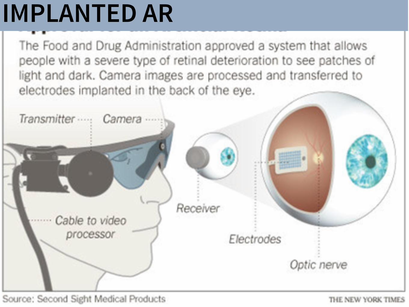
IMPLANTED AR
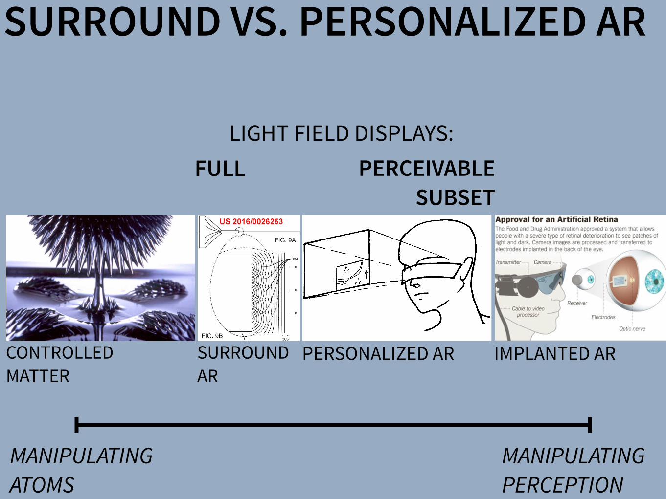
SURROUND VS. PERSONALIZED AR
MANIPULATING ATOMS
MANIPULATING PERCEPTION
CONTROLLED MATTER
PERSONALIZED AR IMPLANTED ARSURROUND AR
There have been a number of shape displays based on pin architecture. The FEELEX project [14] was one of the early attempts to design combined shapes and computer graphics displays that can be explored by touch. FEELEX consisted of several mechanical pistons actuated by motors and cov-ered by a soft silicon surface. The images were projected onto its surface and synchronized with the movement of the pistons, creating simple shapes.
Lumen [32] is a low resolution, 13 by 13-pixel, bit-map display where each pixel can also physically move up and down (Figure 4). The resulting display can present both 2D graphic images and moving physical shapes that can be observed, touched, and felt with the hands. The 2D position sensor built into the surface of Lumen allows users to input commands and manipulate shapes with their hands.
Other related project are PopUp and Glowbits devices [18, 33]. PopUp consists of an array of rods that can be moved up and down using shape memory alloy actuators. The PopUp, however, does not have a visual and interactive component. Glowbits by Daniel Hirschmann (Figure 3) is a 2D array of rods with attached LEDs; the motorized rods can move up and down and LEDs can change their colors.
Discussion We have overviews a number of reasons why actuation can be used in user interfaces. We summarize them in Table 1.
Applications Examples
Aesthetics Automata, ambient displays, shape displays
Information communication
Ambient displays, haptic displays, shape displays
Mechanical work Robots
Controls—data consistency
Actuated tangibles
People-to-people communication
Haptic displays
Table 1: Applications of actuation in user interfaces
Most of the actual devices potentially span more then one application area and it seems that there is a lot of room for innovation and using some of the actuated interfaces in new application areas. For examples, robots could be used for information communication and ambient displays could be used for people-to-people communication.
Future research in actuated interfaces might attempt to sys-tematically investigate applications of actuated devices for various applications, some if which are perhaps not listed above. In the next section we provide analysis of shape dis-plays and there possible applications.
Figure 3: Shape displays (from top): Protrude, Flow,
Snoil, Aegis Hyposurface, Glowbits
2.1 Runtime Environments for User Interfaces in Ubiquitous Augmented Reality
Figure 2.7: Hand-fixed reference frame: Augmentations move with the hand of the user. Thisexample shows a user discussing a virtual map with another user. To observe themap from di↵erent angles, he can pick it up from the body-fixed toolchest aroundhis belt and put it in his hand.
Figure 2.8: Head-fixed reference frame: Augmentations move with the head gaze of the user.The example shows a map of the environment that supports a navigational task.
A Software Toolkit and Authoring Tools for User Interfaces in Ubiquitous Augmented Reality 21
LIGHT FIELD DISPLAYS: PERCEIVABLE
SUBSET FULL

4.4. Depth Perception 121
Figure 4.26. Retinal disparity (up to 200 m, 6 cm / tan(1/60�)).
arcminute, we get a distance of 200 m where retinal disparity may just beperceivable (Figure 4.26). So we can assume that this kind of stereo visionmay work for up to 200 m in the extreme or, for practical situations andaverage vision, it will work for up to about 100 m. Our ability to detectdi↵erences in distance using stereoscopic cues is called stereo acuity. It isgiven by the smallest di↵erence in the images presented to the two eyes thatcan be detected reliably. In general, stereo acuity is inversely proportionalto the square of the viewing distance.
Thus, the range at which disparity is e↵ective depends mainly on theinterocular distance, the convergence of the eyes, and the distance of theobject. Points that are located close to the horopter (see Section 4.4.1) canbe fused correctly. The range around the horopter at which this is possibleis called Panum’s fusion area. However, in addition to absolute disparity,other factors a↵ect disparity-based depth perception. For example, the gra-dients of the disparities (i.e., the depth gradient) influence depth perceptionand make disparity-based depth perception content dependent. Further-more, the speed at which disparity is processed and depth is perceived canvary significantly between conflicting cues (e.g., inconsistent convergenceand accommodation, see Section 4.4.2) and nonconflicting cues, and an up-per limit to the temporal modulation frequency of disparity exists. A gooddiscussion on disparity-based depth perception can be found in [103].
Accommodation. While convergence and retinal disparity are the mainsource of depth perception, there are others.
Figure 4.27. Accommodation and visual depth of field.
LIGHT FIELD DISPLAYS
WWW.DISPLAYSBOOK.INFO
VISION: DISPLAY AS WINDOW
408 9. Three-Dimensional Displays
Figure 9.35. Light-field recording and reconstruction principle: light rays just passinga window (left), light rays converted into pixel values on a tiny image sensor ofa pinhole camera (center), light rays reproduced by a tiny projector being just aninverted pinhole camera (right).
a distance. In principle, this turns out to be quite simple. Any cameraswith a su�ciently small aperture will just record angles and intensitiesof incident light rays and map them onto the pixels of its image sensors(Figure 9.35). Hence small cameras of, for example, 1 mm in size and asu�cient number of (in this case very tiny) pixels can deliver the light-fielddata for just one window segment, which we will call a pixel of the window.Any camera can in general be seen as an angle-to-position converter. Thisconversion is relatively robust with respect to geometric errors.
Reproducing the light field on a display is straightforward (at least intheory): we could use identical optical assemblies, this time illuminatedmicropixel arrays behind pinhole lenses, working as tiny projectors (Fig-ure 9.36). Each camera/projector pair basically acts like a camera obscura;hence, a small hole, and many small holes simply form a window. What intheory works quite well, will nevertheless cause several problems in practi-cal implementation, as you can imagine. The foremost of these is the sheernumber of pixels. If a normal display has n2 pixels for a n⇥ n resolution,the light field has about n4 (n2 pinhole cameras/projectors with n2 pixelseach, to reproduce a light field as dense as the basic image resolution).Without further measures, this would require a prohibitively large trans-mission bandwidth (same order as a raw hologram) and the technologybuilding such a large and dense assembly is not yet available. Anotherproblem are the tiny camera/projector pixel sizes themselves, down to 1µm in the extreme, leading to problems with light sensitivity/brightnessand noise.
For a practical implementation of light-field recording technology, oneapproach is to use a smaller number of cameras in a less dense array andcalculate the missing window pixels by some kind of interpolation. Forthis to work properly, it is necessary to retrieve information about the 3D
SENSOR ARRAY
DISPLAY ARRAY
120 4. Basics of Visual Perception
• Focus e↵ects (blurring of objects not in the lens focus)
• Haze (softened image parts appear more distant)
• Color (bluish objects appear more distant)
• Motion parallax (images change when the head moves)
• Motion dynamics (objects change sizes and positions, in motion)
Convergence. As explained already, convergence is the inward rotation ofthe eyes when targeting a distant object (Figure 4.24). The state of theeye muscles gives us a hint about depth for up to 10 meters. However, wedon’t get extremely fine angular resolutions at this distance.
Figure 4.24. Convergence (up to 10 m).
Retinal disparity. For longer distances, the di↵erence between the two im-ages projected onto the retinas (called retinal disparity) is far more e�cientthan convergence. Near objects block distant ones at slightly di↵erent po-sitions, resulting in di↵erent images generated by the left and right eyes(Figure 4.25).
The di↵erences at object edges can be perceived up to the crispnesslimit of our vision. With a typical eye-to-eye distance (also called interoc-ular distance) of about six centimeters and an angular resolution of one
Figure 4.25. Binocular (stereo) view and resulting left and right image (stereo pair).
VERGENCE ACCOMMODATION
GOAL: NATURAL HUMAN VISUAL PERCEPTION

FUTURE OCULUS DISPLAYS
MICHAEL ABRASH. OCULUS CONNECT 2 KEYNOTE. OCTOBER 2015

SURROUND AR: MAGIC LEAP

4.4. Depth Perception 121
Figure 4.26. Retinal disparity (up to 200 m, 6 cm / tan(1/60�)).
arcminute, we get a distance of 200 m where retinal disparity may just beperceivable (Figure 4.26). So we can assume that this kind of stereo visionmay work for up to 200 m in the extreme or, for practical situations andaverage vision, it will work for up to about 100 m. Our ability to detectdi↵erences in distance using stereoscopic cues is called stereo acuity. It isgiven by the smallest di↵erence in the images presented to the two eyes thatcan be detected reliably. In general, stereo acuity is inversely proportionalto the square of the viewing distance.
Thus, the range at which disparity is e↵ective depends mainly on theinterocular distance, the convergence of the eyes, and the distance of theobject. Points that are located close to the horopter (see Section 4.4.1) canbe fused correctly. The range around the horopter at which this is possibleis called Panum’s fusion area. However, in addition to absolute disparity,other factors a↵ect disparity-based depth perception. For example, the gra-dients of the disparities (i.e., the depth gradient) influence depth perceptionand make disparity-based depth perception content dependent. Further-more, the speed at which disparity is processed and depth is perceived canvary significantly between conflicting cues (e.g., inconsistent convergenceand accommodation, see Section 4.4.2) and nonconflicting cues, and an up-per limit to the temporal modulation frequency of disparity exists. A gooddiscussion on disparity-based depth perception can be found in [103].
Accommodation. While convergence and retinal disparity are the mainsource of depth perception, there are others.
Figure 4.27. Accommodation and visual depth of field.
PERSONALIZED AR: A SMARTER APPROACH
120 4. Basics of Visual Perception
• Focus e↵ects (blurring of objects not in the lens focus)
• Haze (softened image parts appear more distant)
• Color (bluish objects appear more distant)
• Motion parallax (images change when the head moves)
• Motion dynamics (objects change sizes and positions, in motion)
Convergence. As explained already, convergence is the inward rotation ofthe eyes when targeting a distant object (Figure 4.24). The state of theeye muscles gives us a hint about depth for up to 10 meters. However, wedon’t get extremely fine angular resolutions at this distance.
Figure 4.24. Convergence (up to 10 m).
Retinal disparity. For longer distances, the di↵erence between the two im-ages projected onto the retinas (called retinal disparity) is far more e�cientthan convergence. Near objects block distant ones at slightly di↵erent po-sitions, resulting in di↵erent images generated by the left and right eyes(Figure 4.25).
The di↵erences at object edges can be perceived up to the crispnesslimit of our vision. With a typical eye-to-eye distance (also called interoc-ular distance) of about six centimeters and an angular resolution of one
Figure 4.25. Binocular (stereo) view and resulting left and right image (stereo pair).
KEY IDEA: MEASURE HUMAN VISUAL SYSTEM & DISPLAY SUBSET OF LIGHT FIELD
BENEFIT: REDUCE REQUIRED DISPLAY PIXELS BY SEVERAL ORDERS OF MAGNITUDE
WILL BE ACHIEVED WELL BEFORE SURROUND AR!
VERGENCE ACCOMMODATION

PHILOSOPHY: TRUE AUGMENTED REALITY
There have been a number of shape displays based on pin architecture. The FEELEX project [14] was one of the early attempts to design combined shapes and computer graphics displays that can be explored by touch. FEELEX consisted of several mechanical pistons actuated by motors and cov-ered by a soft silicon surface. The images were projected onto its surface and synchronized with the movement of the pistons, creating simple shapes.
Lumen [32] is a low resolution, 13 by 13-pixel, bit-map display where each pixel can also physically move up and down (Figure 4). The resulting display can present both 2D graphic images and moving physical shapes that can be observed, touched, and felt with the hands. The 2D position sensor built into the surface of Lumen allows users to input commands and manipulate shapes with their hands.
Other related project are PopUp and Glowbits devices [18, 33]. PopUp consists of an array of rods that can be moved up and down using shape memory alloy actuators. The PopUp, however, does not have a visual and interactive component. Glowbits by Daniel Hirschmann (Figure 3) is a 2D array of rods with attached LEDs; the motorized rods can move up and down and LEDs can change their colors.
Discussion We have overviews a number of reasons why actuation can be used in user interfaces. We summarize them in Table 1.
Applications Examples
Aesthetics Automata, ambient displays, shape displays
Information communication
Ambient displays, haptic displays, shape displays
Mechanical work Robots
Controls—data consistency
Actuated tangibles
People-to-people communication
Haptic displays
Table 1: Applications of actuation in user interfaces
Most of the actual devices potentially span more then one application area and it seems that there is a lot of room for innovation and using some of the actuated interfaces in new application areas. For examples, robots could be used for information communication and ambient displays could be used for people-to-people communication.
Future research in actuated interfaces might attempt to sys-tematically investigate applications of actuated devices for various applications, some if which are perhaps not listed above. In the next section we provide analysis of shape dis-plays and there possible applications.
Figure 3: Shape displays (from top): Protrude, Flow,
Snoil, Aegis Hyposurface, Glowbits
2.1 Runtime Environments for User Interfaces in Ubiquitous Augmented Reality
Figure 2.7: Hand-fixed reference frame: Augmentations move with the hand of the user. Thisexample shows a user discussing a virtual map with another user. To observe themap from di↵erent angles, he can pick it up from the body-fixed toolchest aroundhis belt and put it in his hand.
Figure 2.8: Head-fixed reference frame: Augmentations move with the head gaze of the user.The example shows a map of the environment that supports a navigational task.
A Software Toolkit and Authoring Tools for User Interfaces in Ubiquitous Augmented Reality 21
DISPLAYS
SharpView: Improved Clarity of Defocused Content on OpticalSee-Through Head-Mounted Displays
Kohei Oshima⇤ † Kenneth R Moser⇤ ‡ Damien Constantine Rompapas† J. Edward Swan II‡ Sei Ikeda§
Goshiro Yamamoto† Takafumi Taketomi† Christian Sandor† Hirokazu Kato†
†Interactive Media Design LaboratoryNara Institute of Science and Technology
‡Computer Science & EngineeringMississippi State University
§Mobile Computing LaboratoryRitsumeikan University
(a) (b) (c) (d) (e)
Figure 1: The cause and effect of focus blur in Optical See-Through (OST) Head-Mounted Display (HMD) systems. (a) A user wearing the OSTHMD and related hardware used in our study. (b) Simplified schematic of an OST AR system. Blurring occurs when the virtual display screenand real world imagery are viewed at unequal focal distances. (c), (d), (e): Views through an OST Augmented Reality system, where the realworld image (c) is in focus, causing the virtual image (d) to appear blurred; (e) an improved virtual image after application of SharpView.
ABSTRACT
Augmented Reality (AR) systems, which utilize optical see-throughhead-mounted displays, are becoming more common place, withseveral consumer level options already available, and the promise ofadditional, more advanced, devices on the horizon. A common fac-tor among current generation optical see-through devices, though,is fixed focal distance to virtual content. While fixed focus is not aconcern for video see-through AR, since both virtual and real worldimagery are combined into a single image by the display, unequaldistances between real world objects and the virtual display screenin optical see-through AR is unavoidable.
In this work, we investigate the issue of focus blur, in particular,the blurring caused by simultaneously viewing virtual content andphysical objects in the environment at differing focal distances. Weadditionally examine the application of dynamic sharpening filtersas a straight forward, system independent, means for mitigating thiseffect improving the clarity of defocused AR content. We assess theutility of this method, termed SharpView, by employing an adjust-ment experiment in which users actively apply varying amounts ofsharpening to reduce the perception of blur in AR content shown atfour focal disparity levels relative to real world imagery.
Our experimental results confirm that dynamic correctionschemes are required for adequately addressing the presence of blurin Optical See-Through AR. Furthermore, we validate the ability ofour SharpView model to improve the perceived visual clarity of fo-cus blurred content, with optimal performance at focal differenceswell suited for near field AR applications.
Index Terms: H.5.1 [Information Interfaces and Presentation]:
⇤These authors contributed equally.†e-mail: {oshima.kohei.of0, damien.rompapas.dk1, goshiro, takafumi-t,
sandor, kato} @is.naist.jp‡e-mail: [email protected], [email protected]§e-mail: [email protected]
Multimedia Information Systems—Artificial, augmented, and vir-tual realities; I.4.4 [Image Processing and Computer Vision]:Restoration—Wiener filtering
1 INTRODUCTION
Optical See-Through (OST) Head-Mounted Displays (HMDs) haveseen an increase in both popularity and accessibility with the re-lease of several consumer level options, including Google Glassand Epson Moverio BT-200, and announced future offerings, suchas Microsoft’s HoloLens, on the horizon. The transparent displaytechnology used in these HMDs affords a unique experience, allow-ing the user to view on-screen computer generated (CG) contentwhile maintaining a direct view of their environment, a propertyextremely well suited for augmented reality (AR) systems. Un-fortunately, the current generation of consumer-level OST HMDsare only capable of presenting CG content at a single fixed focaldistance. This inherent limitation becomes problematic as the userattempts to simultaneously view the world and CG objects together,inducing focal rivalry as the eye’s optical system must continuouslyadjust to accommodate both the real and virtual items.
Figure 1 (a) and (b) illustrate an OST AR system in which a userconcurrently observes real and CG images at disparate distances.As the eye’s accommodation changes to match the focal distance ofthe real image, Figure 1 (c), the on-screen image appears blurred,Figure 1 (d). Naturally, the amount of blur perceived is directly re-lated to accommodative ability, which varies from person to personand undergoes further changes with age. The majority of individ-uals experience steady decline in accommodative ability betweenchild and adulthood [8], with more rapid decreases beginning toonset between 40–50, and general loss of sensitivity to focal dif-ferences occurring beyond 60 years of age. In order to effectivelyaddress such a wide variance in focal ability across users, flexiblecorrective measures, adaptable to specific user needs, are required.
Prior studies have proposed techniques for directly improvingthe distortion effects caused by the optical combiners within OSTHMDs [16]. However, optical distortion from device specific com-ponents only contributes a constant error. Other prior work has ap-plied image filtering and masking algorithms to video see-through
Subjective Evaluation of a Semi-Automatic Optical See-ThroughHead-Mounted Display Calibration Technique
Kenneth Moser, Student Member, IEEE, Yuta Itoh, Student Member, IEEE, Kohei Oshima, Student Member, IEEE,J. Edward Swan II, Member, IEEE, Gudrun Klinker, Member, IEEE, and Christian Sandor, Member, IEEE
Fig. 1. Experimental hardware and design. (a) Display and camera system. (b) Task layout. (c) Pillars task. (d) Cubes task.
Abstract— With the growing availability of optical see-through (OST) head-mounted displays (HMDs), there is a present need forrobust, uncomplicated, and automatic calibration methods suited for non-expert users. This work presents the results of a user studywhich both objectively and subjectively examines registration accuracy produced by three OST HMD calibration methods: (1) SPAAM,(2) Degraded SPAAM, and (3) Recycled INDICA, a recently developed semi-automatic calibration method. Accuracy metrics usedfor evaluation include subject provided quality values and error between perceived and absolute registration coordinates. Our resultsshow all three calibration methods produce very accurate registration in the horizontal direction but caused subjects to perceive thedistance of virtual objects to be closer than intended. Surprisingly, the semi-automatic calibration method produced more accurateregistration vertically and in perceived object distance overall. User assessed quality values were also the highest for RecycledINDICA, particularly when objects were shown at distance. The results of this study confirm that Recycled INDICA is capable ofproducing equal or superior on-screen registration compared to common OST HMD calibration methods. We also identify a potentialhazard in using reprojection error as a quantitative analysis technique to predict registration accuracy. We conclude with discussingthe further need for examining INDICA calibration in binocular HMD systems, and the present possibility for creation of a closed-loopcontinuous calibration method for OST Augmented Reality.
Index Terms—Calibration, user study, OST HMD, INDICA, SPAAM, eye tracking
1 INTRODUCTION
Optical see-through (OST) augmented reality (AR) systems allow theoverlay of visual information onto a user’s view of the real world. Theprimary benefit of these systems, specifically in conjunction with headmounted display (HMD) hardware, is the ability of the user to maintaina view of the real environment from the perspective of their own eyes.This is in contrast to video see-through (VST) AR systems, in whichusers view the environment from the perspective of a camera. Al-
• Kenneth Moser is with the Department of Computer Science andEngineering at Mississippi State University. E-mail: [email protected]
• Yuta Itoh is with the Department of Informatics at Technical University ofMunich. E-mail: [email protected].
• Kohei Oshima is with the Interactive Media Design Lab in the Departmentof Information Science at Nara Institute of Science and Technology.E-mail: [email protected].
• J. Edward Swan II is with the Department of Computer Science atMississippi State University. E-mail: [email protected].
• Gudrun Klinker is with the Department of Informatics at TechnicalUniversity of Munich. E-mail: [email protected].
• Christian Sandor is with the Interactive Media Design Lab in theDepartment of Information Science at Nara Institute of Science andTechnology. E-mail: [email protected].
Manuscript received 18 Sept. 2014; accepted 10 Jan. 2015. Date ofPublication 20 Jan. 2015; date of current version 23 Mar. 2015.For information on obtaining reprints of this article, please sende-mail to: [email protected].
lowing a continuous hands-free view of the environment also lessenssafety concerns from visibility loss due to hardware malfunction, asis the case in military AR usage [20], where constant sight is of theutmost importance. The utility of both OST and VST AR is furtherenhanced when the location of on-screen information is used to pro-vide additional meaning and context.
In both VST and OST AR, information is fundamentally displayedin one of two reference frames: Screen Space and World Space. Infor-mation shown within screen space is statically positioned and does notappear displayed relative to any particular location or object withinthe world. This type of presentation is common in applications fa-cilitating manufacturing or assembly style tasks where the AR visualcomponents list instruction sets or other environment independent in-formation [4]. On-screen items rendered within world space appearto have a 3D position within the environment and are registered, dis-played relative, to fixed locations or objects. This display method re-quires sufficiently accurate registration between on-screen geometryand the visible environment in order to be effective [19]. Achieving anadequate level of world space registration accuracy requires the effec-tual employment of calibration mechanisms.
The goal of OST HMD calibration is to model the virtual cameraprojection matrix, used to render virtual geometry, such that it closelymatches the real viewing frustum created by the user’s eye and thedisplay optics. Unlike VST AR, where computer vision techniquesare used to correct registration [10, 16, 17], calibration of OST AR isnot straightforward. VST techniques are difficult or impossible to usefor correction in OST displays since the “camera” in these systems is
IEEE TRANSACTIONS ON VISUALIZATION AND COMPUTER GRAPHICS, VOL. 21, NO. ,491 4 APRIL��2015
Digital Object Identifier 10.1109/TVCG.2015.23918 6
1077-2626! 201 IEEE. Personal use is permitted, but republication/redistribution requires IEEE permission.See http://www.ieee.org/publications_standards/publications/rights/index.html for more information.
5�� � � � � �
5
GEOMETRIC ALIGNMENT
REMOVE BLUR ARTIFACTS
CREATE CORRECT BLUR

GEOMETRIC ALIGNMENT: SPAAM
MIHRAN TUCERYAN, YAKUP GENC, AND NASSIR NAVAB. SINGLE-POINT ACTIVE ALIGNMENT METHOD (SPAAM) FOR OPTICAL SEE-THROUGH HMD CALIBRATION FOR AUGMENTED REALITY. PRESENCE: TELEOPERATORS AND VIRTUAL ENVIRONMENTS, 11(3):259-276, JUNE 2002.
ScreenPoint
WorldPoint
tH-PScreenPixel(x,y)
tH-PScreenPixel(x,y)
tH-PScreenPixel(x,y)
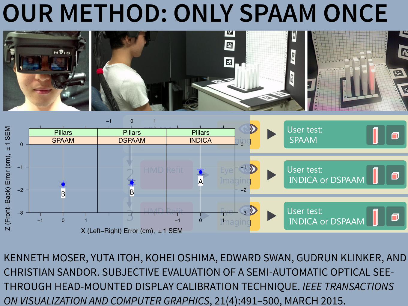
Fig. 9. Stages of the experimental procedure. Every subject performsan initial SPAAM calibration followed by the recording of eye imagesand performance of both tasks using the SPAAM results. The HMD isremoved and refit to the subject, eye images recorded once again, andboth tasks for one of the remaining conditions performed. The proce-dure is repeated a final time for the remaining calibration condition.
the task can be seen in Figure 8.The virtual cube, shown on the HMD, is modeled such that its per-
ceived size should be 2 cm⇥2 cm⇥2 cm and rendered red for increasedcontrast with the real environment. The virtual cube is presented at 10grid locations on both the horizontal and vertical grid for a total of 20trials per calibration condition. The positions of the virtual cube, oneither grid, are randomly selected such that no location is repeated.The display order is chosen such that no consecutive virtual cubes willappear in the same row or column. Ordering of trials between the hor-izontal and vertical cubes grid locations are selected randomly, andsubjects are verbally informed at the start of each trial which grid thevirtual cube should appear upon. Once the virtual cube is displayed at10 locations on both grids, the task ends.
For each of the 20 trials, subjects indicate their selection by statingthe row letter followed by the column number of the grid location towhich they feel the virtual cube is best aligned. Registration accuracyin the vertical direction, Y relative to the tracking coordinate system, ismeasured using the rows of the vertical cubes grid. Registration accu-racy in depth, Z relative to the tracking coordinate system, is measuredby the rows of the horizontal cubes grid. Registration accuracy in thehorizontal direction, X relative to the tracking coordinate system, ismeasured by the columns of both grids. Subjects also verbally providea quality value for each trial of the task. A 1 to 4 subjective scale,with 1 denoting the worst registration and 4 denoting the best registra-tion, are used for this metric. Before beginning the task, subjects areinformed of the quality scale and provided images illustrating the ex-pected visual quality that should be present at each quality level. Thebottom row of Figure 6 shows the images provided to each user.
3.5 ProcedureBoth tasks are performed sequentially, though not always in the sameorder, for each of the three calibration methods. In order to balanceagainst first-order residual effects, the sequence in which tasks are pre-sented is arranged such that no subject performs the tasks, across cal-ibration methods, in the same order. However, because the DegradedSPAAM, as well as the Recycled INDICA, calibration requires an ex-isting projection matrix to already be accessible, the SPAAM calibra-tion is always performed at the start of the experiment for each sub-ject. Since the SPAAM calibration is performed first, the tasks for theSPAAM condition are also always performed before any other calibra-tion condition, since any movement of the HMD on the subject’s headwould require SPAAM to be reperformed. Even though both tasks forSPAAM are conducted first, the ordering of all tasks over all three cal-ibration conditions is never repeated between subjects. In addition, tocounter any effect from the eye imaging phase required by RecycledINDICA, 10 eye images are recorded, though not used, before the startof both SPAAM and Degraded SPAAM task sets. Figure 9 illustratesthe general task ordering and experiment flow for each subject.
At the start of the experiment, the subject is given a thorough expla-nation of the hardware and why calibration is required. The SPAAMcalibration process is then described to the user with emphasis placed
on the need for stable accurate screen-world alignments. The HMD isthen placed onto the subject’s head and adjusted so that their left eyeis visually centered behind the left eye piece. The SPAAM calibrationprocedure as described in section 3.3 is then performed.
Once SPAAM calibration is completed, the subject is seated in frontof the task table. Using the eye imaging camera, 10 images of theuser’s left eye are taken. The subjective quality scale for each task isreviewed and each subject is given the images shown in Figure 6. Thesubject then performs both experimental tasks, as described in section3.4, using their SPAAM results. After completion of both tasks, theHMD is removed from the subject’s head, and a 5 minute break allot-ted to give the subject ample rest before the next set of tasks.
After the 5 minute break, the HMD is replaced onto the subject’shead with care only taken to ensure their left eye is positioned properlybehind the eye piece and graphics are clearly seen on the display. Eyeimaging is performed once again, and 10 new images of the subject’sleft eye taken. Both experimental tasks are repeated again for eitherthe Degraded SPAAM or Recycled INDICA condition. The order inwhich subjects perform the Degraded SPAAM or Recycled INDICAcalibration condition is arranged to match the previously mentionedcriteria, that no subject would perform tasks in the some order acrossconditions. Following the completion of both tasks, the HMD is re-moved once again and a 5 minute respite given to the subject. After-wards, the HMD is refit a final time and 10 more images taken of thesubject’s left eye. Tasks for the remaining condition, either DegradedSPAAM or Recycled INDICA, are then performed.
4 EXPERIMENTAL RESULTS
We obtain our experimental results by taking the difference betweenthe subject reported row/column positions and the actual locationswhere the virtual object should have appeared. The difference along arow indicates registration error in the horizontal, X, direction relativeto the tracking coordinate frame, with negative error indicating a uservalue that is to the left of the actual. We take the difference along a col-umn to represent error in the vertical, Y, direction for measures takenduring a trial on the vertical cubes grid, with negative error indicatinga user value that is below the actual. Difference along a column inboth the Pillars and horizontal cubes grid trials is interpreted as errorin distance, Z, relative to the tracking coordinate frame, with negativeerror indicating a response that is closer to the user then the actual.
We also convert the error measures from the difference in gridsquares to distance measures. The size of grid squares for both grids inthe Cubes task is 2cm⇥2cm. Thus, we equate an error of 1 to an errorof 2cm in the respective direction. Similarly, the spacing of pillars inthe Pillars task is 4cm, since each 2cm⇥2cm pillar is separated by a2cm row or column. Therefore, we equate an error of 1 pillar to anerror of 4cm in the respective direction.
The subject-provided quality values are also normalized for ouranalysis. Measures for both tasks are normalized to values from 1to 4. Converting both tasks to an identical scale allows for direct andfair comparisons between tasks.
4.1 Subjective MeasuresWe used repeated-measures analysis of variance (ANOVA) to test theeffect of the different algorithms in each experimental condition. Foreach test, if Mauchly’s test indicated non-sphericity, we adjusted thep-value according to the Huynh-Feldt e value; in such cases we re-port e along with the ANOVA F-test. In addition, we used the RyanREGWQ post-hoc homogenous subset test to determine how the threealgorithms differed from each other, as described by Howell [12].
Figure 10 provides mean normalized quality values across subjectsfor each task under each calibration method. Quality values obtainedfor the Cubes task are shown separated by grid type, Cubes-V repre-senting measures for the vertical cubes grid and Cubes-H representingmeasures for the horizontal cubes grid. ANOVA, performed on thevalues within each subplot of Figure 10, shows a significant main ef-fect of calibration method in both the Pillars task (F(2,24) = 5.03, p=0.015) and the horizontal cubes grid (F(2,24) = 6.65, p = 0.013,e =
ET AL.:MOSER SUBJECTIVEEVALUATIONOF ASEMI-AUTOMATIC OPTICALSEE-THROUGH HEAD-MOUNTED DISPLAY 496
Algorithm
Qua
lity
Rat
ing,
±1
SEM
2.5
2.7
2.9
3.1
3.3
3.5
SPAAM DSPAAM INDICA
●
●●
Pillars
SPAAM DSPAAM INDICA
● ●●
Cubes−V
SPAAM DSPAAM INDICA2.5
2.7
2.9
3.1
3.3
3.5
●
●
●
Cubes−H
A"A"
B" A"
B"B"
A" A" A"
Fig. 10. Mean subjective quality values for each calibration method dur-ing each task, normalized to a 1–4 scale with 1 denoting the lowestquality and 4 the highest. The values shown are across subjects withindividual plots for the Pillars task as well as each grid of the Cubes task.Cubes-V shows normalized quality for the vertical cubes grid. Cubes-Hshows normalized quality for the horizontal cubes grid. Means with thesame letter, within each plot, are not significantly different at p 0.05(Ryan REGWQ post-hoc homogeneous subset test).
X (Left−Right) Error (cm), ± 1 SEMZ (F
ront−B
ack)
Erro
r (cm
), ±
1 SE
M
−3
−2
−1
0
−1 0 1
●
SPAAMPillars
−1 0 1
●
DSPAAMPillars
−1 0 1−3
−2
−1
0
●
INDICAPillars
A"B"B"
Fig. 11. Mean Pillars task error along the X (Left-Right) and Z (Front-Back) direction relative to the tracking coordinate frame. 0 indicatesno error. Error is reported as a distance value, with every 4 cm of er-ror equating to a 1 pillar location difference in the respective direction.Means with the same letter are not significantly different at p 0.05(Ryan REGWQ post-hoc homogeneous subset test).
0.71). The vertical cubes grid condition shows no significant differ-ence between calibration methods (F < 1). The normalized qualityvalues also show that subjects report Recycled INDICA registrations,viewed on the Pillars and the horizontal cubes grid, to be of higherquality over Degraded SPAAM. While SPAAM quality is rated nearlyequal to Recycled INDICA in the Pillars task, it rates lowest in hori-zontal cubes grid trials. All three calibration methods produce nearlyidentical quality ratings across subjects in vertical cubes grid trials1.
Registration Error in Pillars Task Figure 11 provides the regis-tration error results for the Pillars task converted into distance mea-sures. Error in both the X, Left-Right, and Z, Front-Back, directionsrelative to the tracking coordinate frame are provided. ANOVA of Xdimension error shows no significant main effect due to calibrationmethod (F < 1). Results show subject perceived error is near perfect,0 error, along the X direction. All three calibration methods produceerror in the Z direction, however, with subjects perceiving the registra-
1In addition to ANOVA, we also performed the non-parametric Friedmanand Kruskal-Wallis rank sum tests for subjective judgements. The Friedmanrank sum test shows a significant main effect for the Pillars (c2(2) = 5.45, p =0.066) and Cubes-H (c2(2) = 13.06, p = 0.0015) tasks, but not for the Cubes-V task (c2(2) = 0.15). The Kruskal-Wallis rank sum test also shows a sig-nificant main effect for the Pillars (c2(2) = 18.92, p < 0.001) and Cubes-H(c2(2) = 21.21, p < 0.001) tasks, but not for the Cubes-V task (c2(2) = 0.98).In contrast to ANOVA, the Friedman rank sum test looses power by ignoringlarge portions of data; reducing either 624 (Pillars) or 390 (Cubes-H, Cubes-V)data values into 39 to conduct the test. The Kruskal-Wallis rank sum test devi-ates from ANOVA by producing a large amount of power, because it does notmodel the within-subjects design of the data. Nevertheless, the interpretationof the results remains the same, regardless of the analysis method used.
X (Left−Right) Error (cm), ± 1 SEMY (U
p−D
own)
Erro
r (cm
), ±
1 SE
M
−3
−2
−1
0
−1 0 1
●
SPAAMCubes−V
−1 0 1
●
DSPAAMCubes−V
−1 0 1−3
−2
−1
0
●
INDICACubes−V
A"
B"B"
Fig. 12. Mean vertical cubes grid task error along the Y (Up-Down)and X (Left-Right) direction relative to the tracking coordinate frame.0 indicates no error. Error in each direction is reported as a distancevalue, with every 2 cm of error equating to a 1 grid square locationdifference in the respective direction. Means with the same letter are notsignificantly different at p 0.05 (Ryan REGWQ post-hoc homogeneoussubset test).
X (Left−Right) Error (cm), ± 1 SEMZ (F
ront−B
ack)
Erro
r (cm
), ±
1 SE
M
−5
−4
−3
−2
−1 0 1
●
SPAAMCubes−H
−1 0 1
●
DSPAAMCubes−H
−1 0 1−5
−4
−3
−2
●
INDICACubes−H
A"
B"B"
Fig. 13. Mean horizontal cubes grid task error along the Z (Front-Back)and X (Left-Right) direction relative to the tracking coordinate frame.0 indicates no error. Error in each direction is reported as a distancevalue, with every 2 cm of error equating to a 1 grid square locationdifference in the respective direction. Means with the same letter are notsignificantly different at p 0.05 (Ryan REGWQ post-hoc homogeneoussubset test).
tion of virtual objects to be closer than intended for every case. Recy-cled INDICA results show a shift in distance perception away from theuser and closer to the correct location. ANOVA also indicates a highlysignificant effect of calibration method (F(2,24) = 14.011, p< 0.001)along the Z direction.
Registration Error in Cubes Task Figures 12 and 13 show theregistration error results for the Cubes task separated by each grid.Results for trials conducted on the horizontal cubes grid are shown inFigure 13 and provide error in both the X, Left-Right, and Z, Front-Back, directions relative to the tracking coordinate frame. ANOVAperformed along each direction shows a significant main effect of cal-ibration method along the Z direction (F(2,24) = 7.37, p = 0.003),with no effect along the X (F < 1). All three calibration methodsproduce equally, near 0, error along the X direction and Recycled-INDICA produces the least Z error.
Results for trials conducted on the vertical Cubes grid are shownin Figure 12 and provide error in both the X, Left-Right, and Y, Up-Down, directions relative to the tracking coordinate frame. ANOVAshows no main effect of calibration method on results along the X di-rection (F < 1). A main effect of calibration method is detected alongthe Y direction (F(2,24) = 10.96, p = 0.0016,e = 0.75). Similar tothe Pillars and horizontal cubes grid, all three calibration methods pro-duce near 0 errors along X. Y error is less under the Recycled INDICAcondition, with both SPAAM and Degraded SPAAM resulting in sim-ilar error amounts.
IEEE TRANSACTIONS ON VISUALIZATION AND COMPUTER GRAPHICS, VOL. 21, NO. ,4 APRIL��2015497Subjective Evaluation of a Semi-Automatic Optical See-ThroughHead-Mounted Display Calibration Technique
Kenneth Moser, Student Member, IEEE, Yuta Itoh, Student Member, IEEE, Kohei Oshima, Student Member, IEEE,J. Edward Swan II, Member, IEEE, Gudrun Klinker, Member, IEEE, and Christian Sandor, Member, IEEE
Fig. 1. Experimental hardware and design. (a) Display and camera system. (b) Task layout. (c) Pillars task. (d) Cubes task.
Abstract— With the growing availability of optical see-through (OST) head-mounted displays (HMDs), there is a present need forrobust, uncomplicated, and automatic calibration methods suited for non-expert users. This work presents the results of a user studywhich both objectively and subjectively examines registration accuracy produced by three OST HMD calibration methods: (1) SPAAM,(2) Degraded SPAAM, and (3) Recycled INDICA, a recently developed semi-automatic calibration method. Accuracy metrics usedfor evaluation include subject provided quality values and error between perceived and absolute registration coordinates. Our resultsshow all three calibration methods produce very accurate registration in the horizontal direction but caused subjects to perceive thedistance of virtual objects to be closer than intended. Surprisingly, the semi-automatic calibration method produced more accurateregistration vertically and in perceived object distance overall. User assessed quality values were also the highest for RecycledINDICA, particularly when objects were shown at distance. The results of this study confirm that Recycled INDICA is capable ofproducing equal or superior on-screen registration compared to common OST HMD calibration methods. We also identify a potentialhazard in using reprojection error as a quantitative analysis technique to predict registration accuracy. We conclude with discussingthe further need for examining INDICA calibration in binocular HMD systems, and the present possibility for creation of a closed-loopcontinuous calibration method for OST Augmented Reality.
Index Terms—Calibration, user study, OST HMD, INDICA, SPAAM, eye tracking
1 INTRODUCTION
Optical see-through (OST) augmented reality (AR) systems allow theoverlay of visual information onto a user’s view of the real world. Theprimary benefit of these systems, specifically in conjunction with headmounted display (HMD) hardware, is the ability of the user to maintaina view of the real environment from the perspective of their own eyes.This is in contrast to video see-through (VST) AR systems, in whichusers view the environment from the perspective of a camera. Al-
• Kenneth Moser is with the Department of Computer Science andEngineering at Mississippi State University. E-mail: [email protected]
• Yuta Itoh is with the Department of Informatics at Technical University ofMunich. E-mail: [email protected].
• Kohei Oshima is with the Interactive Media Design Lab in the Departmentof Information Science at Nara Institute of Science and Technology.E-mail: [email protected].
• J. Edward Swan II is with the Department of Computer Science atMississippi State University. E-mail: [email protected].
• Gudrun Klinker is with the Department of Informatics at TechnicalUniversity of Munich. E-mail: [email protected].
• Christian Sandor is with the Interactive Media Design Lab in theDepartment of Information Science at Nara Institute of Science andTechnology. E-mail: [email protected].
Manuscript received 18 Sept. 2014; accepted 10 Jan. 2015. Date ofPublication 20 Jan. 2015; date of current version 23 Mar. 2015.For information on obtaining reprints of this article, please sende-mail to: [email protected].
lowing a continuous hands-free view of the environment also lessenssafety concerns from visibility loss due to hardware malfunction, asis the case in military AR usage [20], where constant sight is of theutmost importance. The utility of both OST and VST AR is furtherenhanced when the location of on-screen information is used to pro-vide additional meaning and context.
In both VST and OST AR, information is fundamentally displayedin one of two reference frames: Screen Space and World Space. Infor-mation shown within screen space is statically positioned and does notappear displayed relative to any particular location or object withinthe world. This type of presentation is common in applications fa-cilitating manufacturing or assembly style tasks where the AR visualcomponents list instruction sets or other environment independent in-formation [4]. On-screen items rendered within world space appearto have a 3D position within the environment and are registered, dis-played relative, to fixed locations or objects. This display method re-quires sufficiently accurate registration between on-screen geometryand the visible environment in order to be effective [19]. Achieving anadequate level of world space registration accuracy requires the effec-tual employment of calibration mechanisms.
The goal of OST HMD calibration is to model the virtual cameraprojection matrix, used to render virtual geometry, such that it closelymatches the real viewing frustum created by the user’s eye and thedisplay optics. Unlike VST AR, where computer vision techniquesare used to correct registration [10, 16, 17], calibration of OST AR isnot straightforward. VST techniques are difficult or impossible to usefor correction in OST displays since the “camera” in these systems is
IEEE TRANSACTIONS ON VISUALIZATION AND COMPUTER GRAPHICS, VOL. 21, NO. ,491 4 APRIL��2015
Digital Object Identifier 10.1109/TVCG.2015.23918 6
1077-2626! 201 IEEE. Personal use is permitted, but republication/redistribution requires IEEE permission.See http://www.ieee.org/publications_standards/publications/rights/index.html for more information.
5�� � � � � �
5
KENNETH MOSER, YUTA ITOH, KOHEI OSHIMA, EDWARD SWAN, GUDRUN KLINKER, AND CHRISTIAN SANDOR. SUBJECTIVE EVALUATION OF A SEMI-AUTOMATIC OPTICAL SEE-THROUGH HEAD-MOUNTED DISPLAY CALIBRATION TECHNIQUE. IEEE TRANSACTIONS ON VISUALIZATION AND COMPUTER GRAPHICS, 21(4):491–500, MARCH 2015.
OUR METHOD: ONLY SPAAM ONCE

Figure 1. (a): Simplified schematic of an OST AR system. Blurring occurs when the virtualdisplay screen and real world imagery are viewed at unequal focal distances. (b, c): Viewsthrough an OST AR system. (b) shows ideal AR, both of the CG and the object in the real worldappears to be clear. (c) shows an actual AR example wherein the CG looks blurry. When theuser focuss on the object in the real world, the CG cannot avoid being blurred because of thedifference in depth.
2
DESIRED MOST DISPLAYS
BLUR ARTIFACTS

BLUR ARTIFACTS
DESIRED MOST DISPLAYS
Figure 1. (a): Simplified schematic of an OST AR system. Blurring occurs when the virtualdisplay screen and real world imagery are viewed at unequal focal distances. (b, c): Viewsthrough an OST AR system. (b) shows ideal AR, both of the CG and the object in the real worldappears to be clear. (c) shows an actual AR example wherein the CG looks blurry. When theuser focuss on the object in the real world, the CG cannot avoid being blurred because of thedifference in depth.
2
SharpView: Improved Clarity of Defocused Content on OpticalSee-Through Head-Mounted Displays
Kohei Oshima⇤ † Kenneth R Moser⇤ ‡ Damien Constantine Rompapas† J. Edward Swan II‡ Sei Ikeda§
Goshiro Yamamoto† Takafumi Taketomi† Christian Sandor† Hirokazu Kato†
†Interactive Media Design LaboratoryNara Institute of Science and Technology
‡Computer Science & EngineeringMississippi State University
§Mobile Computing LaboratoryRitsumeikan University
(a) (b) (c) (d) (e)
Figure 1: The cause and effect of focus blur in Optical See-Through (OST) Head-Mounted Display (HMD) systems. (a) A user wearing the OSTHMD and related hardware used in our study. (b) Simplified schematic of an OST AR system. Blurring occurs when the virtual display screenand real world imagery are viewed at unequal focal distances. (c), (d), (e): Views through an OST Augmented Reality system, where the realworld image (c) is in focus, causing the virtual image (d) to appear blurred; (e) an improved virtual image after application of SharpView.
ABSTRACT
Augmented Reality (AR) systems, which utilize optical see-throughhead-mounted displays, are becoming more common place, withseveral consumer level options already available, and the promise ofadditional, more advanced, devices on the horizon. A common fac-tor among current generation optical see-through devices, though,is fixed focal distance to virtual content. While fixed focus is not aconcern for video see-through AR, since both virtual and real worldimagery are combined into a single image by the display, unequaldistances between real world objects and the virtual display screenin optical see-through AR is unavoidable.
In this work, we investigate the issue of focus blur, in particular,the blurring caused by simultaneously viewing virtual content andphysical objects in the environment at differing focal distances. Weadditionally examine the application of dynamic sharpening filtersas a straight forward, system independent, means for mitigating thiseffect improving the clarity of defocused AR content. We assess theutility of this method, termed SharpView, by employing an adjust-ment experiment in which users actively apply varying amounts ofsharpening to reduce the perception of blur in AR content shown atfour focal disparity levels relative to real world imagery.
Our experimental results confirm that dynamic correctionschemes are required for adequately addressing the presence of blurin Optical See-Through AR. Furthermore, we validate the ability ofour SharpView model to improve the perceived visual clarity of fo-cus blurred content, with optimal performance at focal differenceswell suited for near field AR applications.
Index Terms: H.5.1 [Information Interfaces and Presentation]:
⇤These authors contributed equally.†e-mail: {oshima.kohei.of0, damien.rompapas.dk1, goshiro, takafumi-t,
sandor, kato} @is.naist.jp‡e-mail: [email protected], [email protected]§e-mail: [email protected]
Multimedia Information Systems—Artificial, augmented, and vir-tual realities; I.4.4 [Image Processing and Computer Vision]:Restoration—Wiener filtering
1 INTRODUCTION
Optical See-Through (OST) Head-Mounted Displays (HMDs) haveseen an increase in both popularity and accessibility with the re-lease of several consumer level options, including Google Glassand Epson Moverio BT-200, and announced future offerings, suchas Microsoft’s HoloLens, on the horizon. The transparent displaytechnology used in these HMDs affords a unique experience, allow-ing the user to view on-screen computer generated (CG) contentwhile maintaining a direct view of their environment, a propertyextremely well suited for augmented reality (AR) systems. Un-fortunately, the current generation of consumer-level OST HMDsare only capable of presenting CG content at a single fixed focaldistance. This inherent limitation becomes problematic as the userattempts to simultaneously view the world and CG objects together,inducing focal rivalry as the eye’s optical system must continuouslyadjust to accommodate both the real and virtual items.
Figure 1 (a) and (b) illustrate an OST AR system in which a userconcurrently observes real and CG images at disparate distances.As the eye’s accommodation changes to match the focal distance ofthe real image, Figure 1 (c), the on-screen image appears blurred,Figure 1 (d). Naturally, the amount of blur perceived is directly re-lated to accommodative ability, which varies from person to personand undergoes further changes with age. The majority of individ-uals experience steady decline in accommodative ability betweenchild and adulthood [8], with more rapid decreases beginning toonset between 40–50, and general loss of sensitivity to focal dif-ferences occurring beyond 60 years of age. In order to effectivelyaddress such a wide variance in focal ability across users, flexiblecorrective measures, adaptable to specific user needs, are required.
Prior studies have proposed techniques for directly improvingthe distortion effects caused by the optical combiners within OSTHMDs [16]. However, optical distortion from device specific com-ponents only contributes a constant error. Other prior work has ap-plied image filtering and masking algorithms to video see-through
REAL PHOTO
“MATCHING” IMAGE

SharpView: Improved Clarity of Defocused Content on OpticalSee-Through Head-Mounted Displays
Kohei Oshima⇤ † Kenneth R Moser⇤ ‡ Damien Constantine Rompapas† J. Edward Swan II‡ Sei Ikeda§
Goshiro Yamamoto† Takafumi Taketomi† Christian Sandor† Hirokazu Kato†
†Interactive Media Design LaboratoryNara Institute of Science and Technology
‡Computer Science & EngineeringMississippi State University
§Mobile Computing LaboratoryRitsumeikan University
(a) (b) (c) (d) (e)
Figure 1: The cause and effect of focus blur in Optical See-Through (OST) Head-Mounted Display (HMD) systems. (a) A user wearing the OSTHMD and related hardware used in our study. (b) Simplified schematic of an OST AR system. Blurring occurs when the virtual display screenand real world imagery are viewed at unequal focal distances. (c), (d), (e): Views through an OST Augmented Reality system, where the realworld image (c) is in focus, causing the virtual image (d) to appear blurred; (e) an improved virtual image after application of SharpView.
ABSTRACT
Augmented Reality (AR) systems, which utilize optical see-throughhead-mounted displays, are becoming more common place, withseveral consumer level options already available, and the promise ofadditional, more advanced, devices on the horizon. A common fac-tor among current generation optical see-through devices, though,is fixed focal distance to virtual content. While fixed focus is not aconcern for video see-through AR, since both virtual and real worldimagery are combined into a single image by the display, unequaldistances between real world objects and the virtual display screenin optical see-through AR is unavoidable.
In this work, we investigate the issue of focus blur, in particular,the blurring caused by simultaneously viewing virtual content andphysical objects in the environment at differing focal distances. Weadditionally examine the application of dynamic sharpening filtersas a straight forward, system independent, means for mitigating thiseffect improving the clarity of defocused AR content. We assess theutility of this method, termed SharpView, by employing an adjust-ment experiment in which users actively apply varying amounts ofsharpening to reduce the perception of blur in AR content shown atfour focal disparity levels relative to real world imagery.
Our experimental results confirm that dynamic correctionschemes are required for adequately addressing the presence of blurin Optical See-Through AR. Furthermore, we validate the ability ofour SharpView model to improve the perceived visual clarity of fo-cus blurred content, with optimal performance at focal differenceswell suited for near field AR applications.
Index Terms: H.5.1 [Information Interfaces and Presentation]:
⇤These authors contributed equally.†e-mail: {oshima.kohei.of0, damien.rompapas.dk1, goshiro, takafumi-t,
sandor, kato} @is.naist.jp‡e-mail: [email protected], [email protected]§e-mail: [email protected]
Multimedia Information Systems—Artificial, augmented, and vir-tual realities; I.4.4 [Image Processing and Computer Vision]:Restoration—Wiener filtering
1 INTRODUCTION
Optical See-Through (OST) Head-Mounted Displays (HMDs) haveseen an increase in both popularity and accessibility with the re-lease of several consumer level options, including Google Glassand Epson Moverio BT-200, and announced future offerings, suchas Microsoft’s HoloLens, on the horizon. The transparent displaytechnology used in these HMDs affords a unique experience, allow-ing the user to view on-screen computer generated (CG) contentwhile maintaining a direct view of their environment, a propertyextremely well suited for augmented reality (AR) systems. Un-fortunately, the current generation of consumer-level OST HMDsare only capable of presenting CG content at a single fixed focaldistance. This inherent limitation becomes problematic as the userattempts to simultaneously view the world and CG objects together,inducing focal rivalry as the eye’s optical system must continuouslyadjust to accommodate both the real and virtual items.
Figure 1 (a) and (b) illustrate an OST AR system in which a userconcurrently observes real and CG images at disparate distances.As the eye’s accommodation changes to match the focal distance ofthe real image, Figure 1 (c), the on-screen image appears blurred,Figure 1 (d). Naturally, the amount of blur perceived is directly re-lated to accommodative ability, which varies from person to personand undergoes further changes with age. The majority of individ-uals experience steady decline in accommodative ability betweenchild and adulthood [8], with more rapid decreases beginning toonset between 40–50, and general loss of sensitivity to focal dif-ferences occurring beyond 60 years of age. In order to effectivelyaddress such a wide variance in focal ability across users, flexiblecorrective measures, adaptable to specific user needs, are required.
Prior studies have proposed techniques for directly improvingthe distortion effects caused by the optical combiners within OSTHMDs [16]. However, optical distortion from device specific com-ponents only contributes a constant error. Other prior work has ap-plied image filtering and masking algorithms to video see-through
KOHEI OSHIMA, KENNETH R MOSER, DAMIEN CONSTANTINE ROMPAPAS, J EDWARD SWAN II, SEI IKEDA, GOSHIRO YAMAMOTO, TAKAFUMI TAKETOMI, CHRISTIAN SANDOR, AND HIROKAZU KATO. IMPROVED CLARITY OF DEFOCUSSED CONTENT ON OPTICAL SEE-THROUGH HEAD-MOUNTED DISPLAYS. IN IEEE SYMPOSIUM ON 3D USER INTERFACES, PAGES 173–181, GREENVILLE, SOUTH CAROLINA, USA, MARCH 2016.
OUR METHOD: SHARPVIEW
SHARPVIEWREAL PHOTO
SharpView: Improved Clarity of Defocused Content on OpticalSee-Through Head-Mounted Displays
Kohei Oshima⇤ † Kenneth R Moser⇤ ‡ Damien Constantine Rompapas† J. Edward Swan II‡ Sei Ikeda§
Goshiro Yamamoto† Takafumi Taketomi† Christian Sandor† Hirokazu Kato†
†Interactive Media Design LaboratoryNara Institute of Science and Technology
‡Computer Science & EngineeringMississippi State University
§Mobile Computing LaboratoryRitsumeikan University
(a) (b) (c) (d) (e)
Figure 1: The cause and effect of focus blur in Optical See-Through (OST) Head-Mounted Display (HMD) systems. (a) A user wearing the OSTHMD and related hardware used in our study. (b) Simplified schematic of an OST AR system. Blurring occurs when the virtual display screenand real world imagery are viewed at unequal focal distances. (c), (d), (e): Views through an OST Augmented Reality system, where the realworld image (c) is in focus, causing the virtual image (d) to appear blurred; (e) an improved virtual image after application of SharpView.
ABSTRACT
Augmented Reality (AR) systems, which utilize optical see-throughhead-mounted displays, are becoming more common place, withseveral consumer level options already available, and the promise ofadditional, more advanced, devices on the horizon. A common fac-tor among current generation optical see-through devices, though,is fixed focal distance to virtual content. While fixed focus is not aconcern for video see-through AR, since both virtual and real worldimagery are combined into a single image by the display, unequaldistances between real world objects and the virtual display screenin optical see-through AR is unavoidable.
In this work, we investigate the issue of focus blur, in particular,the blurring caused by simultaneously viewing virtual content andphysical objects in the environment at differing focal distances. Weadditionally examine the application of dynamic sharpening filtersas a straight forward, system independent, means for mitigating thiseffect improving the clarity of defocused AR content. We assess theutility of this method, termed SharpView, by employing an adjust-ment experiment in which users actively apply varying amounts ofsharpening to reduce the perception of blur in AR content shown atfour focal disparity levels relative to real world imagery.
Our experimental results confirm that dynamic correctionschemes are required for adequately addressing the presence of blurin Optical See-Through AR. Furthermore, we validate the ability ofour SharpView model to improve the perceived visual clarity of fo-cus blurred content, with optimal performance at focal differenceswell suited for near field AR applications.
Index Terms: H.5.1 [Information Interfaces and Presentation]:
⇤These authors contributed equally.†e-mail: {oshima.kohei.of0, damien.rompapas.dk1, goshiro, takafumi-t,
sandor, kato} @is.naist.jp‡e-mail: [email protected], [email protected]§e-mail: [email protected]
Multimedia Information Systems—Artificial, augmented, and vir-tual realities; I.4.4 [Image Processing and Computer Vision]:Restoration—Wiener filtering
1 INTRODUCTION
Optical See-Through (OST) Head-Mounted Displays (HMDs) haveseen an increase in both popularity and accessibility with the re-lease of several consumer level options, including Google Glassand Epson Moverio BT-200, and announced future offerings, suchas Microsoft’s HoloLens, on the horizon. The transparent displaytechnology used in these HMDs affords a unique experience, allow-ing the user to view on-screen computer generated (CG) contentwhile maintaining a direct view of their environment, a propertyextremely well suited for augmented reality (AR) systems. Un-fortunately, the current generation of consumer-level OST HMDsare only capable of presenting CG content at a single fixed focaldistance. This inherent limitation becomes problematic as the userattempts to simultaneously view the world and CG objects together,inducing focal rivalry as the eye’s optical system must continuouslyadjust to accommodate both the real and virtual items.
Figure 1 (a) and (b) illustrate an OST AR system in which a userconcurrently observes real and CG images at disparate distances.As the eye’s accommodation changes to match the focal distance ofthe real image, Figure 1 (c), the on-screen image appears blurred,Figure 1 (d). Naturally, the amount of blur perceived is directly re-lated to accommodative ability, which varies from person to personand undergoes further changes with age. The majority of individ-uals experience steady decline in accommodative ability betweenchild and adulthood [8], with more rapid decreases beginning toonset between 40–50, and general loss of sensitivity to focal dif-ferences occurring beyond 60 years of age. In order to effectivelyaddress such a wide variance in focal ability across users, flexiblecorrective measures, adaptable to specific user needs, are required.
Prior studies have proposed techniques for directly improvingthe distortion effects caused by the optical combiners within OSTHMDs [16]. However, optical distortion from device specific com-ponents only contributes a constant error. Other prior work has ap-plied image filtering and masking algorithms to video see-through
“MATCHING” IMAGE

BASIC IDEA: PRE-SHARPENING

VISUALIZATION OF PSF
HTTPS://BENEDIKT-BITTERLI.ME/FEMTO.HTML

ESTIMATING EYE PSF
The diffraction pattern of the light during this process is modeled bya PSF. If defects are present in the physical structures of the eye, aswould be the case in individuals with inhibited vision, a static PSFis sufficient for determining the optical power requirements neces-sary for corrective lenses able to adjust or redirect the light raysback through the proper focal point within the eye. This same pro-cedure can be analogously expressed, within the image processingdomain, as a deconvolution operation between the image focusedon the retina and the PSF. Therefore, if a PSF is known in advance,it is possible to restore a degraded image through deconvolution.
Common deconvolution operations include inverse filtering,Wiener filtering, and the iterative Richardson-Lucy algorithm [11].Difficulty in performing deconvolution with a PSF arises, how-ever, due to inaccuracies in the diffraction pattern model. Okumuraet al. [30] have utilized information from captured images of 2Dmarkers to estimate the PSF of a camera based system. Unfortu-nately, the same principles are not applicable to the human eye,since only the user themselves have access to the perceived im-age. Additionally, techniques used to measure a user’s PSF requireexpensive or large physical hardware, such as auto-refractometers,and a processing demand which is not suited for real time applica-tions [32]. Our SharpView algorithm overcomes these limitationsby employing a simplified PSF model based on three user and sys-tem specific parameters: pupil diameter, distance to real world gazepoint, and focal distance of the HMD display screen.
3.1 Image ConvolutionIn general, the convolution of an image o with a point spread func-tion p produces a blurred image b.
b = o⇤ p (1)
The symbol ⇤ represents the convolution operation. Equation (1)can be expressed within the spatial frequency domain as
B = O ·P (2)
where B, P and O represent Fourier transforms of b, p and o, re-spectively. A blurred image can, likewise, be corrected throughapplication of the inverse PSF, O0 = B/P. However, the follow-ing Wiener Deconvolution is optimal for performing this task withminimal noise.
O0 =B ·P
|P|2 + |C|2(3)
Here, P represents the complex conjugate of P. C is a constantto prevent instability of the solution when values of P are small.We apply this same principle to OST AR in order to create a finalsharpened on-screen image with improved visibility over the orig-inal. We accomplish this by applying the Wiener filter, adjustedusing the estimated PSF of the user, to rendered images O and dis-play the resulting sharpened image S to the HMD.
S =O ·P
|P|2 + |C|2(4)
3.2 PSF EstimationEffectively counteracting dynamic focus blur, caused by accom-modative differences between the display screen and world in OSTHMDs, requires the PSF to be determined at run-time. We accom-plish this by using a simplified Gaussian function to approximatethe PSF, which allows for faster update rates but with a reduction inaccuracy.
We generate our approximation by modeling the intensity of thelight rays, emitted from the display screen, intersecting varying
points on the retina. The intensity distribution, p, can be repre-sented by the following function.
P(x,y) =1
2ps2 exp(� x2 + y2
2s2 ) (5)
In equation (5), s represents the focal blur size, while x and y rep-resent the pixel position of the emanating screen point. Our sim-plified PSF model, therefore, requires only one parameter, s , to bedetermined at run time.
Consider the simple system, shown in Figure 2, used to modelthe combined optical system of the eye and OST HMD screen. Thecenter lens, in this system, represents the internal crystalline lensof the eye and the right imaging plane characterizes the retina. Asthe user’s gaze fixates at point M in the real environment, the lighttraveling from this point creates an image at point m on the eye’simaging plane, after passing through the lens. Similarly, light emit-ted from point M0 on the HMD screen is imaged at point m0 on theretina. While the user’s focus is centered on the real environment,all of the light rays from the display will be improperly focused bythe lens causing on-screen content to appear blurred. The radius ofthis blur is equal to s in our Gaussian function, equation (5). Thiss can be derived from the basic triangle ratio and lens equations asfollows:
s =av2(
1u0
� 1u) (6)
Once obtained, it is then necessary to scale from the eye’s imageplane back to the virtual display. If the radius of display blur isexpressed as sd , the ratio between the eye’s image plane and screenis expressed as follows.
s : sd = v : u0 (7)
Here, sd is directly obtainable from equations (6) and (7),
sd =a2(1� u0
u) (8)
where a is pupil diameter, u is distance from the eye to the realworld gaze point, and u0 represents the distance from eye to HMDimage plane. When performing the actual convolution between thefilter and screen image, generally, sd may be converted to pixelsize, scaling the values based on the dot matrix of the specific dis-play used. Our complete SharpView algorithm simplifies blur cor-rection into a single convolution operation, where the filter is con-structed from an estimated PSF, requiring only three parameters, allmeasurable at runtime.
Further simplification might be considered by presuming a con-stant pupil size during usage. However, numerous studies [12, 1,35, 33] have shown that pupil size is not only dependent on lightingbut also mental load and task concentration, making live measure-ment of the pupil advisable. Additional system complexity may
Figure 2: Optical system formed by the user’s eye and an OST HMD.The imaging plane corresponds to the user’s retina and the lens aper-ture to the user’s pupil.
Gaussian function
! is calculated from!
Simplified Gaussian function to approximate the PSF decreases processing time allowing faster update rates

OUR EXPERIMENT
(a) (b) (c)
Figure 6: View through the HMD of a reference and sharpened virtual image pair during the adjustment task. The rendered gauge provides anindication of the amount of sharpening correction applied. (a) Low, (b) moderate, and (c) high amounts of sharpening. Though color and contrastappear to differ, both on-screen and reference images used during the experiment were black and white. The images shown are capturedthrough a digital camera and do not necessarily reflect the actual visual appearance experienced by the subjects during use.
are presented one at a time to the subject, Figure 4 (a). For eachcross-hair, the subject is instructed to fixate and maintain their gazeon the center of the cross for approximately 5 seconds. Duringthis fixation period, the gaze angle, in relation to the eye-trackingcamera, is recorded. Using the known screen locations of eachcross-hair and the recorded gaze angle measurements, a mappingbetween gaze direction and screen pixels is determined. The Pupil-Labs open-source software provides built-in routines for both col-lecting the gaze angle data and performing the mapping calcula-tions.
The second phase of calibration is intended to properly positionthe AR content within the subject’s field of view. We perform thisoperation by rendering a red square to the HMD screen and allow-ing subjects to manually adjust its location. Using a hand held con-troller, subjects are allowed to move the square up and down andside-to-side until the right edge of the square is aligned flush withthe left edge of a real reference image placed in front of the display,Figure 4 (b). Proper vertical positioning occurs when the center ofthe square aligns with the center of the reference image.
After successful calibration, We are able to track the subjects’gaze across the HMD screen and detect when fixation is moved to-ward on-screen content. We simply mute, turn off, all graphics asa counter measure preventing subjects from focusing onto the vir-tual screen. Once gaze is removed from the AR content’s location,graphics are restored and the experiment continued.
In addition to gaze information, the eye-tracking software alsoprovided a rough measure of pupil diameter in terms of image pix-els. Presuming a standard iris diameter of 12mm [6, 10], we wereable to calculate the distance scale between camera pixels of the eyetracking camera and physical distance. Using this same scale, rede-termined per subject at the start of the experiment, the approximatepupil diameter in mm for each subject is estimated at run-time.
4.4 Adjustment TaskWe utilize a simple adjustment task to obtain measures for theamount of perceived focus blur and preferred level of sharpeningcorrection for subjects viewing real and virtual content through ourOST AR system. Focus blur is induced by making subjects fixatetheir gaze upon real reference images, placed in front of the display,at distances differing from the actual focal distance of the HMD. Avirtual image, identical to the real reference image, is then renderedto the display screen. The subject will consequently perceive therendered image as blurred, even though it is unaltered, due to thefocal disparity between the reference image and HMD.
(a) (b)
(c) (d)
Figure 7: The four black and white stone patters used as both refer-ence and on-screen imagery during the adjustment task.
The images used in our experiment were chosen to provide largeamounts of high frequency visual information, such as clearly de-fined edges for example. Four asymmetric stone patterns wereselected for use during the experiment itself, Figure 7, with anadditional four images used during training sets before data wasrecorded. The resolution of the images displayed to the HMD,as well as the size of the reference images, was adjusted so thatboth images subtended a constant 6� of visual angle. In order tominimize effects from color difference between the printed and on-screen images, both the HMD and reference photos were kept blackand white.
We presented the reference images at four distance levels, 25cm,50cm, 100cm, and 500cm, as measured from the subject’s eye.These distances were selected in order to obtain measures over a
(a) (b)
Figure 3: The OST HMD system used in our experiment. (a) An ex-ample subject wearing the HMD and eye tracking combination. Theright eye-piece is covered to produce a monocular view. (b) Closerview of the attached camera used for tracking subject gaze and mea-suring pupil size.
arise from the necessity to record the fixation distance between theuser’s eye and real object under focus. While it is possible to cal-culate the user’s fixation through on-line vergence angle measure-ments provided by stereoscopic eye-tracking [7, 9, 37], an alterna-tive method leveraging known 3D environmental layout informa-tion, compiled off-line using a depth sensor or camera such as theMicrosoft Kinect, may be more suited for current consumer sys-tems. Correlating the intersection of the user’s gaze with this pre-rendered environment model, would facilitate rough estimation forthe current focal demand of the user.
4 EXPERIMENTAL DESIGN
In order to develop an effective improvement strategy for correct-ing focus blur in OST AR, measures for the amount of blur per-ceived by users must be obtained. Since focus blur occurs duringaccommodation rivalry between physical and on-screen content, itis essential to define the level of awareness users have to the pres-ence of blur in rendered images. We developed SharpView based onthe premise that perceived focus blur varies according to the focaldisparity between the display and world. Therefore, if a physicalobject is viewed at a distance approximately equal to the focal dis-tance of the HMD, very little focus blur should occur. However, ifthe distance to the physical object greatly differs from the HMD fo-cal distance, a large amount of focus blur should be observed. Thisimplies that a static correction scheme will not suffice, but rather adynamic range of sharpening levels is required.
Based on this presumption, we designed and implemented a userstudy investigation to quantify user perception of focus blur withinan OST AR system. Our experimental hypotheses are two-fold.First, we believe preferential sharpening levels for each subject willvary according to the magnitude of focal disparity, with more sharp-ening desired at greater disparities, and very low sharpening de-grees chosen for the low focal disparity conditions. Secondly, weanticipate the users to select sharpening values which will follow asimilar trend as that predicted by our SharpView model over-all.
4.1 Subjects13 participants (10 male, 3 female), between the ages of 22 and33, participated in our study. All subjects were university studentsrecruited through email solicitation. Each subject was required toprovide written consent before proceeding with the study and wasprovided monetary compensation for their time. 8 of the 13 sub-jects stated that they possessed normal uncorrected vision. The re-maining 5 required the use of corrective contact lenses, which wereworn throughout the duration of the task. Subjects were provided athorough explanation of the experimental hardware and procedurebefore beginning any aspect of the experiment.
4.2 Experiment PlatformAn Epson Moverio BT-200 OST HMD is used as the primary dis-play worn by each subject. The Moverio is a binocular display
(a) (b)
Figure 4: Views of the eye tracking calibration process, as seenthrough the HMD. (a) An on-screen cross-hair used during the gaze-to-screen mapping phase of calibration. (b) Correct placement of thered square during the position adjustment phase of system calibra-tion.
(a) (b)
Figure 5: Location of subjects relative to reference images placed at25 cm (a) and 500 cm (b) from the subjects’ eyes.
capable of presenting stereo imagery at 60Hz with a maximum res-olution of 960⇥540 per eye. The focal distance of the display wasboth independently measured and confirmed by the manufacturerto be approximately 7m. In order to remove effects due to stere-oscopy and binocular rivalry, the right eye piece of the display iscovered with a patch of black opaque cloth, Figure 3 (a). We at-tached a Microsoft LifeCam HD-6000 webcam, set to a resolutionof 1280⇥720 at 30fps, beneath the left eye piece, Figure 3 (b). Thecamera itself is modified by removing the infrared and adding a vis-ible light filter along with a pair of IR LEDs. Measurements for theleft eye’s pupil diameter, as well as gaze direction, are made usingimages captured by the HD-6000 and processed via version 0.4.5of the PupilLabs open-source eye tracking software [22]. Accu-racy of the gaze tracking was confirmed to within 1� with measuresrecorded at the frame rate limitation of the cameras, 30Hz. TheOpenCV image processing library is used to perform the deconvo-lution required by SharpView and generate the on-screen imagesdisplayed at run time. A wireless hand held controller is addition-ally used to record subject adjustments and responses during allcalibration and experimental tasks.
4.3 Eye TrackingIn order to induce and maintain the presence of focus blur duringour experimental task, subjects must be forced to fixate their gazeonto physical objects in the world and also be prevented from shift-ing their focus onto on-screen content. We incorporate an eye track-ing process into our OST HMD system making it possible to deter-mine the subject’s gaze direction and impose countermeasures toprevent accommodation change when their gaze moves toward ARimagery. A brief calibration process is required, though, in order tomap the subject’s gaze onto screen coordinates of the OST display.We actually employ a two phase procedure to both calibrate oureye-tracking system as well as adjust the placement of AR contentwithin the subject’s field of view.
First, we determine the direction of the subject’s gaze with re-lation to the HMD screen. This process is accomplished through astandard gaze mapping routine, commonly used to calibrate com-mercial and consumer eye-tracking systems. A set of 12 cross-hairs, positioned to uniformly cover the on-screen area of the HMD,
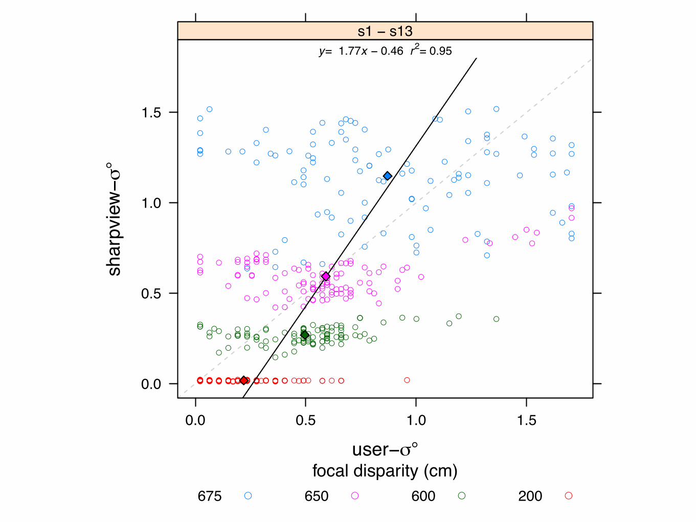
user−σ°
shar
pvie
w−σ°
0.0
0.5
1.0
1.5
2.0
●●● ●● ●
●●
●●●●
● ●●●
●● ● ● ●● ●●
●●●●●● ●●
y= 0.56x + 0.17 r2= 0.24s1
0.0 0.5 1.0 1.5
●
●
● ●●
●● ●
●●●●●● ●●
● ●● ●●●● ●
● ●●●●●●●
y= 0.74x + 0.15 r2= 0.68s2
● ●●●● ●● ●
●●● ●●● ●●
●●● ●●●● ●
●●●●●●●●
y= 2.08x − 0.04 r2= 0.50s3
0.0 0.5 1.0 1.5
●●
●●●●
●●
●●● ●
●●●●
●●● ●●● ●●
●●● ●●●●●
y= 1.47x − 0.17 r2= 0.50s4
●● ●●●
●●●
●●●
●● ● ● ●
●●●●● ●●●
●●●●● ●●●
y= 1.63x − 0.35 r2= 0.79s5
0.0 0.5 1.0 1.5
● ●●●
●●●● ●●
●● ●●● ●
●●●● ●● ●●●●●● ●●●●
y= 2.45x − 0.57 r2= 0.86s6
●●●●
● ●●●
●● ●● ●●●●
● ●●● ●●●●
●●●● ●●●●
y= 0.97x − 0.14 r2= 0.99s7
0.0 0.5 1.0 1.5
●●
●●●●●●
●●
●● ●● ●●
● ●●● ●●●●
● ●●●● ●● ●
y= 4.78x − 0.53 r2= 0.85s8
●●●●
●
●
●●
● ●●●
● ●●●
●● ●●● ●●●
●● ●●●●●●
y= 0.89x + 0.02 r2= 0.10s9
0.0 0.5 1.0 1.5
●●●
● ●
●●●
● ●●●● ●● ●
●● ●●●●● ●
● ●● ●●● ●●
y= 2.08x − 0.81 r2= 1.00s10
●●●●●●●●
●●●●●● ●●
●●●●●●● ●
●● ●● ●●●●
y= 1.22x − 0.27 r2= 0.97s11
0.0 0.5 1.0 1.5
●●●●●
●●●
●●● ●●●●●
●●●● ●●●●
●●● ●●●●●
y= 1.21x − 0.30 r2= 0.85s12
0.0
0.5
1.0
1.5
2.0
● ● ●●
●● ●●
●●●●● ●●●
● ●● ● ●● ●●
●●● ●●●● ●
y= 0.77x − 0.12 r2= 0.82s13
focal disp. (cm)675650600200
●
●
●
●
Figure 9: Comparison between user-selected sigma and the sigma predicted by our SharpView algorithm; both values are expressed as degreesof visual angle. The data points are color-coded according to focal disparity. The regression line is fit to the centroid (filled diamonds) of eachdistance. Ideal correspondence between our SharpView model and user preference is represented by a dashed line along the diagonal.
user−σ°
shar
pvie
w−σ°
0.0
0.5
1.0
1.5
0.0 0.5 1.0 1.5
●●
● ●
●●
●
●
●
●
●●
●
●
● ●
● ●●
●● ●● ●
●
●
●
●
●
●
●
●
●●●●
●
●
●
●
● ●
●
●
●●●●
●●
●●
● ●●
●
●
●
● ●
●●
●●
●●
●
●
●
●
●●
●
●●
●
●
●●●
●
●●●
●●
●●
●
● ●●
●
●
●●
●●
●
●
●
●●
●
●
●
● ●
● ●●●
● ●●●
●●● ●
●● ● ●●●●●
●
●●
●
●●●
●
●
●
●
●● ● ● ●
●
●
● ● ●●● ●
●● ●
● ●●●●
●
●
●
● ●●
●●
●●
●
●
●●
●●
● ●●●
●●
●●
●●
●●
●● ●
●
●●
●●
●
●●●
● ●● ●●● ●●
●● ● ● ●● ●●
● ●● ●●● ● ●
●●● ●● ●● ●●●● ●●●
●●
●● ●●●●● ●
● ● ●●●●
● ●
● ●●● ●●●●●●●●●
● ● ●
●● ●
● ●●● ●●● ●●●●● ●●● ●●●●● ●●● ●● ●●● ●●
●●● ●● ●●
● ●●●●● ●●● ●●●● ●● ●●●●●●●●● ●● ● ●● ●● ● ●●● ●● ● ●● ●●●● ● ●●● ●● ●● ●●● ●● ●●●● ●● ●●● ●● ●● ●● ● ●● ● ●● ●●●● ●● ●● ● ● ●●● ●●●●● ●● ● ● ●●● ●
y= 1.77x − 0.46 r2= 0.95s1 − s13
focal disparity (cm)675 650 600 200● ● ● ●
Figure 10: Data from Figure 9, averaged over all users. Ideal cor-respondence between our SharpView model and user preference isrepresented by a dashed line along the diagonal.
Figure 8 provides a side by side comparison of the user-s se-lections and the modeled SharpView-s . Visual inspection revealsa noticeable trend of increasing user-s values with increasing focaldistance disparity. The mean and standard error of the mean forthe four user-s groupings are also shown in Figure 8. Repeatedmeasures analysis of variance (ANOVA) across the user-s group-ings, confirms that user-s significantly differs according to distance(F(3,36) = 16.7, p < 0.001). A Ryan REGWQ post-hoc homoge-neous subset test additionally indicates that all means are signifi-cantly different at p 0.05.
The modeled SharpView-s , likewise, increases with larger focaldisparity distance, though at a slightly higher rate than the subjectselected values. Paired ANOVA testing across the separate userand SharpView-s groupings at each disparity level shows that the
subject-chosen user-s values do significantly differ from the mod-eled SharpView-s at the 200cm, 600cm, and 675cm focus dispar-ity levels (F(1,12) = 39.2, p < 0.001, F(1,12) = 22.35, p < 0.001,and F(1,12) = 4.705, p ⇡ 0.051, respectively). However no signif-icance was found between user and SharpView-s at a disparity of650cm (F < 1).
We obtain a second metric for quantifying the modeling accuracyof our SharpView algorithm by plotting user-s versus SharpView-s . Figure 9 provides a per-subject s comparison, while Fig-ure 10 shows the comparison with all data combined. While boththe SharpView model and accommodative functions of the userare both exponential in nature, our correspondence plots are in-tended to visualize the correlation between our sharpening predic-tion and user preference. Therefore, an ideal modeling betweenour SharpView and user selections will result in a linear trend, ex-pressed in each plot as a dashed line along the diagonal.
The regression lines, shown in black, are fit to the centroids of thedata clusters associated with recordings from each of the four focaldisparity levels. Inspection of per-subject comparisons, once again,indicates that the modeled SharpView-s values increase at a largerrate than the subject-selected s values. The complete data com-parison, Figure 10, confirms that this is indeed the case. However,it is clearly evident that the modeled SharpView-s is most accu-rate at the 650cm focus disparity level, matching the ANOVA find-ings. Additionally, the clustering exhibited by data points withineach distance level also reveals that subjects had the most consis-tent agreement on s choices at the 200cm, 600cm, and 650cm dis-parities. Mean and standard deviation values for both the user andSharpView-s results at each distance level are provided in Table 1.
6 DISCUSSION
The impact of our experimental results is two-fold. Foremost, thesignificant difference in user-s values across focus disparities, asexhibited in Figure 8, confirms that subjects are not only able toperceive the effects of focus blur on AR content, but also the im-provement in clarity afforded by sharpening. Secondly, the sig-nificant differences in user selected correction validates our claimthat focus blur mitigation requires a dynamic solution, such as ourSharpView algorithm.
Since the focal disparity is lowest at the 500cm reference im-age distance—200cm focal difference—we would also expect theeffects from focus blur to be lowest during trials at this level. Con-versely, as the disparity rises, the amount of focus blur perceived in

MATCHING BLUR: REAL & VIRTUAL
DAMIEN CONSTANTINE ROMPAPAS, AITOR ROVIRA, SEI IKEDA, ALEXANDER PLOPSKI, TAKAFUMI TAKETOMI, CHRISTIAN SANDOR, AND HIROKAZU KATO. EYEAR: REFOCUSABLE AUGMENTED REALITY CONTENT THROUGH EYE MEASUREMENTS. DEMO AT IEEE INTERNATIONAL SYMPOSIUM ON MIXED AND AUGMENTED REALITY, MERIDA, MEXICO, SEPTEMBER 2016. BEST DEMO AWARD
1.4 Contribution
EyeAR is the first system to take an alternative approach to creating an AR DoF CGimage capable of being viewed using a commodity OST-HMD by measuring the user’s eye.Because of this we are able to achieve high-quality CG DoF images which match the user’sview of the real scene.
An example of these results can be seen in Figure 1.5. However, as our system measuresthe user’s eye in real-time, the content displayed on the screen is dynamic, meaning theusers can focus their eyes on any part of the scene, and the CG will always reflect the stateof the user’s eye (See Figure 1.7 for an example).
Figure 1.5: Example of a user looking into the box enclosure. Left: Without EyeAR, Youcan observe the DoF mismatch between CG (white hat) and real scene (dragon). Right:With EyeAR, the CG’s DoF accurately matches the natural DoF of the real scene.
Because EyeAR is able to create accurate DoF images on OST-HMD display, all OST-HMDs should include this functionality. However, the applications of EyeAR are notlimited to creating indistinguishable AR content as our system directly measures the eye.
For example, Sharpview (Oshima et al., 2015) sharpens content displayed on the screenby approximating the user’s eye point spread function based on the user’s eye pupil sizeand focal length, with EyeAR integrated into all commodity OST-HMD displays Shaprviewcan directly use the measurements EyeAR obtains.
We can also directly compare EyeAR with a Light Field Display to see the pros andcons of using EyeAR (refer to Figure 1.7).
5
Chapter 1
Introduction
The human visual system always focuses at a distinct depth and objects that lie at di↵erentdepths appear blurred, as the user’s focus depth changes di↵erent objects come in and outof focus. This phenomenon is known as Depth of Field (DoF). Augmented Reality (AR) isa technology which superimposes Computer Graphics (CG) images onto a users view of thereal world. With AR on Optical See-Through Head-Mounted Displays (OST-HMDs), userscan observe the CG and the real world simultaneously due to the nature of the transparentdisplay, however, this DoF phenomenon is not observed for AR on commodity OST-HMDdevices. This causes a mismatch between the observed CG and the real scene (See thecircled section in Figure 1.1).
Figure 1.1: Typical AR on OST-HMD scene with the user focusing on the objects inthe back, for objects in front there is a DoF mismatch between CG (hat) and real scene(dragon) highlighted with the white circle.
1
OUR DISPLAYMOST DISPLAYS

MATCHING BLUR: REAL & VIRTUAL

CONCEPT OF EYEARMeasure Eye - pupil size- focal length
Render DOF Image (Realtime Pathtracing with NVIDIA Optix)
Correct Image Depth Difference (SharpView)
Display Result
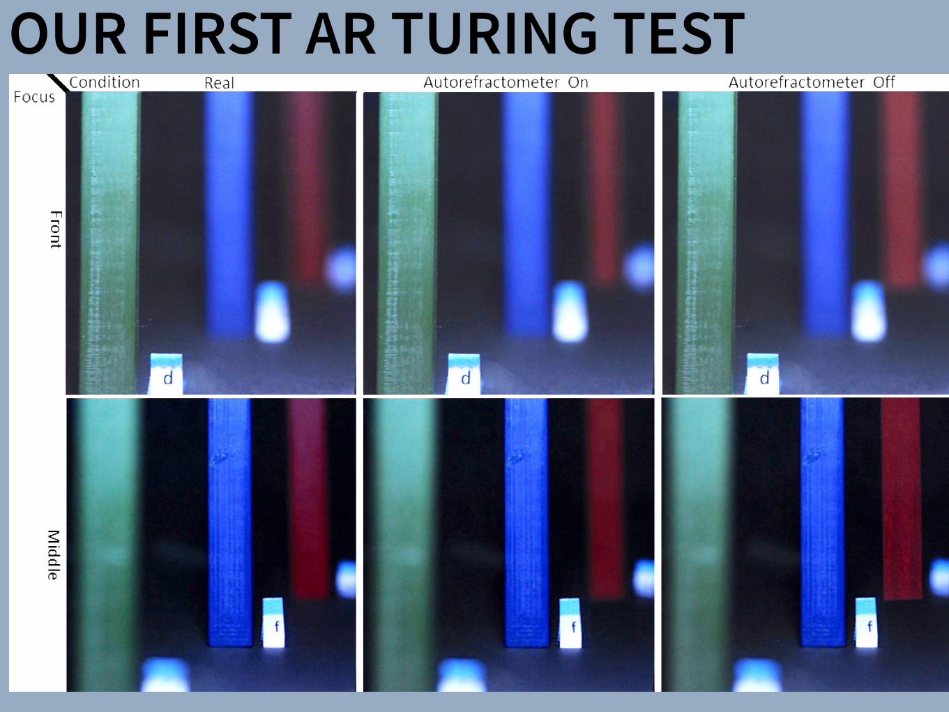
OUR FIRST AR TURING TEST

OUR FIRST AR TURING TEST
0.4
0.5
0.6
0.7
0.8
Virtual Pillar
Cor
rect
gue
sses
(%)
Green (0.25m) Blue (0.375m) Red (0.5m)
Autorefractometeronoff
Figure 7: Overall percentage of correct guessesfor each pillar when the autorefractometer was on(red line) and off (blue line). text in figure toosmall. some text crossing boundaries
Estimate Std.error Wald Pr(> |W |) 95% Conf. intervalIntercept -0.561 0.565 0.99 0.3202 -1.67 to 0.55TrialSequence 0.152 0.058 6.96 0.0083 0.04 to 0.27Autorefractometer=on -1.841 0.273 45.65 < 10�10 -2.38 to -1.31VirtualPillar 0.236 0.158 2.23 0.1357 -0.07 to 0.55Age 0.010 0.013 0.58 0.4475 -0.02 to 0.04Gender 0.872 0.304 8.23 0.0041 0.28 to 1.47
Table 1: Coefficients and p-values of the experimental variables of a linear modelfitting using GEE with correlation structure=exchangeable. The p-values show thatAutorefractometer is the main contributor to the model but not the only one, alsogender and TrialSequence are significant. Trial sequence referred to the order trialswere carried out, showing that there is a learning effect.
and CIC=3.34, having again Autorefractometer (p< 10�10) thestrongest predictor, but both TrialSequence (p=0.022) and Gender(p=0.013) also need to be taken into account.
5.7 Discussion
We had two hypotheses when running this experiment. The firsthypothesis, H1, was that with the autorefractometer on, the userwould not be able to distinguish the virtual pillar from the real ones.We only found support for this hypothesis when the virtual pillarwas the blue one, but not for the other two, green, and red. Wespeculate that the distance where the pillars were placed in relationto the position of the semi-transparent display is a very importantfactor to correct the display-eye focal depth difference, as discussedin Section 3.3. The error that resulted from this difference made iteasier to distinguish the virtual pillars from the real counterparts.We also need to take into account that there was a learning effect.Participants found it easier to guess it correctly towards the finaltrials.
The second hypothesis, H2, was that with the autorefractome-ter off, participants would identify the virtual pillar correctly moreoften compared to the other experimental condition, when the datafrom the autorrefractometer was used to adjust the blurriness of thevirtual pillar. The results from the regression analysis using GEEsupport this hypothesis, showing that Autrorefractometer was thestrongest predictor in the different models where we tested. Besidesthe learning effect aforementioned, we also found out that there wasa significant difference between genders. On the other side, the ageof the participant was not a significant contributor of our model.
6 FUTURE WORK AND CONCLUSIONS
There is a need for refocusable CG for OST-AR in order to createrealistic scenes where objects are placed at different depths. In thispaper, we have presented the design of a display concept based onthe user’s eye measurements as an alternative to LFDs, then imple-mented three tabletop prototypes that emulate an OST-HMD setupand can accurately match the DoF of virtual objects to real objects.We then evaluated our third prototype with a user study to verifyour claims. Our results strongly support H2, which stated that ourclosed loop system creates significantly more realistic renderingsthan a system, which does not measure the user’s eyes. However,our first hypothesis H1 was rejected for the pillars in the back-ground and foreground, likely due to the CG reconstruction errorthat is caused by the screen-object disparity.
We have identified three main areas for future work: First, andmost important, improve the prototype to deal with the screen-object disparity. Second, to miniaturize the autorefractometer and
integrate it into an OST-HMD. Third, refine our methodology forconducting AR Turing Tests and carry out several more.
Concerning the screen-object disparity, SharpView could be theideal solution. However, we still need to investigate how to builduser-specific PSFs, including 3D PSFs, and model the dynamicaccommodation process. In order to achieve the required opticalpower, we are now considering programmable optical elements;this approach has been successfully demonstrated in the dual prob-lem of increasing the DoF of projectors through coded apertures [8]and fast focal sweeps based on a shape-changing lens [12].
In terms of portability, we aim to study how to reduce the sizeof our system to the point that it can be integrated into an HMD.Additionally, the update rate our system (5Hz) can be sufficient torefocus between distances several meters away from the eye, butcan lead to noticeable latency when quickly refocusing between ob-jects placed near the eye as in our tabletop setup, where the farthestobject was 0.5m away.
It is also part of our future work to improve the experimentaldesign and standarize a methodology to carry out AR Turing Tests.In our experiment, we used three pillars with plain textures. We aimto carry out experiments using more complex scenes that includeobjects of different shapes, materials with different parameters ofsurface rugosity, and models of light scattering. With increasinglycomplex scenes, experimental measurements could collect ordinalinstead of binary answers from participants in order to provide morefacetted results.
Referring back to our previously published taxonomy of AR dis-plays [31], EyeAR is an instance of a Personalized AR display, asopposed to the LFD approach, which is an instance of Surround AR.We are convinced that our approach has significant advantages overLFDs, a very obvious one being backwards compatibility. We envi-sion an EyeAR hardware module, which can turn any legacy OST-HMD into a powerful display, perceptually equivalent to a LFD.
ACKNOWLEDGEMENTS
Support for this work is provided by the Japan Society for thePromotion of Science under awards Grant-in-Aid for ScientificResearch (B) #15H02737 and Challenging Exploratory Research#15K12084. We would further like to thank Kohei Oshima forhis help with integrating SharpView into P1. We would also liketo thank Georg Klein for the suggestion to put virtual hats on ourdragons.
REFERENCES
[1] E. H. Adelson and J. R. Bergen. The plenoptic function and the ele-ments of early vision. Vision and Modeling Group, Media Laboratory,Massachusetts Institute of Technology, 1991.
12 PARTICIPANTS12 GUESSES
VIRTUAL
REAL

HOLOLENS VERSIONOUR METHOD (EXAGGERATED BLUR)
CONVENTIONAL

DISPLAYSSharpView: Improved Clarity of Defocused Content on OpticalSee-Through Head-Mounted Displays
Kohei Oshima⇤ † Kenneth R Moser⇤ ‡ Damien Constantine Rompapas† J. Edward Swan II‡ Sei Ikeda§
Goshiro Yamamoto† Takafumi Taketomi† Christian Sandor† Hirokazu Kato†
†Interactive Media Design LaboratoryNara Institute of Science and Technology
‡Computer Science & EngineeringMississippi State University
§Mobile Computing LaboratoryRitsumeikan University
(a) (b) (c) (d) (e)
Figure 1: The cause and effect of focus blur in Optical See-Through (OST) Head-Mounted Display (HMD) systems. (a) A user wearing the OSTHMD and related hardware used in our study. (b) Simplified schematic of an OST AR system. Blurring occurs when the virtual display screenand real world imagery are viewed at unequal focal distances. (c), (d), (e): Views through an OST Augmented Reality system, where the realworld image (c) is in focus, causing the virtual image (d) to appear blurred; (e) an improved virtual image after application of SharpView.
ABSTRACT
Augmented Reality (AR) systems, which utilize optical see-throughhead-mounted displays, are becoming more common place, withseveral consumer level options already available, and the promise ofadditional, more advanced, devices on the horizon. A common fac-tor among current generation optical see-through devices, though,is fixed focal distance to virtual content. While fixed focus is not aconcern for video see-through AR, since both virtual and real worldimagery are combined into a single image by the display, unequaldistances between real world objects and the virtual display screenin optical see-through AR is unavoidable.
In this work, we investigate the issue of focus blur, in particular,the blurring caused by simultaneously viewing virtual content andphysical objects in the environment at differing focal distances. Weadditionally examine the application of dynamic sharpening filtersas a straight forward, system independent, means for mitigating thiseffect improving the clarity of defocused AR content. We assess theutility of this method, termed SharpView, by employing an adjust-ment experiment in which users actively apply varying amounts ofsharpening to reduce the perception of blur in AR content shown atfour focal disparity levels relative to real world imagery.
Our experimental results confirm that dynamic correctionschemes are required for adequately addressing the presence of blurin Optical See-Through AR. Furthermore, we validate the ability ofour SharpView model to improve the perceived visual clarity of fo-cus blurred content, with optimal performance at focal differenceswell suited for near field AR applications.
Index Terms: H.5.1 [Information Interfaces and Presentation]:
⇤These authors contributed equally.†e-mail: {oshima.kohei.of0, damien.rompapas.dk1, goshiro, takafumi-t,
sandor, kato} @is.naist.jp‡e-mail: [email protected], [email protected]§e-mail: [email protected]
Multimedia Information Systems—Artificial, augmented, and vir-tual realities; I.4.4 [Image Processing and Computer Vision]:Restoration—Wiener filtering
1 INTRODUCTION
Optical See-Through (OST) Head-Mounted Displays (HMDs) haveseen an increase in both popularity and accessibility with the re-lease of several consumer level options, including Google Glassand Epson Moverio BT-200, and announced future offerings, suchas Microsoft’s HoloLens, on the horizon. The transparent displaytechnology used in these HMDs affords a unique experience, allow-ing the user to view on-screen computer generated (CG) contentwhile maintaining a direct view of their environment, a propertyextremely well suited for augmented reality (AR) systems. Un-fortunately, the current generation of consumer-level OST HMDsare only capable of presenting CG content at a single fixed focaldistance. This inherent limitation becomes problematic as the userattempts to simultaneously view the world and CG objects together,inducing focal rivalry as the eye’s optical system must continuouslyadjust to accommodate both the real and virtual items.
Figure 1 (a) and (b) illustrate an OST AR system in which a userconcurrently observes real and CG images at disparate distances.As the eye’s accommodation changes to match the focal distance ofthe real image, Figure 1 (c), the on-screen image appears blurred,Figure 1 (d). Naturally, the amount of blur perceived is directly re-lated to accommodative ability, which varies from person to personand undergoes further changes with age. The majority of individ-uals experience steady decline in accommodative ability betweenchild and adulthood [8], with more rapid decreases beginning toonset between 40–50, and general loss of sensitivity to focal dif-ferences occurring beyond 60 years of age. In order to effectivelyaddress such a wide variance in focal ability across users, flexiblecorrective measures, adaptable to specific user needs, are required.
Prior studies have proposed techniques for directly improvingthe distortion effects caused by the optical combiners within OSTHMDs [16]. However, optical distortion from device specific com-ponents only contributes a constant error. Other prior work has ap-plied image filtering and masking algorithms to video see-through
SharpView: Improved Clarity of Defocused Content on OpticalSee-Through Head-Mounted Displays
Kohei Oshima⇤ † Kenneth R Moser⇤ ‡ Damien Constantine Rompapas† J. Edward Swan II‡ Sei Ikeda§
Goshiro Yamamoto† Takafumi Taketomi† Christian Sandor† Hirokazu Kato†
†Interactive Media Design LaboratoryNara Institute of Science and Technology
‡Computer Science & EngineeringMississippi State University
§Mobile Computing LaboratoryRitsumeikan University
(a) (b) (c) (d) (e)
Figure 1: The cause and effect of focus blur in Optical See-Through (OST) Head-Mounted Display (HMD) systems. (a) A user wearing the OSTHMD and related hardware used in our study. (b) Simplified schematic of an OST AR system. Blurring occurs when the virtual display screenand real world imagery are viewed at unequal focal distances. (c), (d), (e): Views through an OST Augmented Reality system, where the realworld image (c) is in focus, causing the virtual image (d) to appear blurred; (e) an improved virtual image after application of SharpView.
ABSTRACT
Augmented Reality (AR) systems, which utilize optical see-throughhead-mounted displays, are becoming more common place, withseveral consumer level options already available, and the promise ofadditional, more advanced, devices on the horizon. A common fac-tor among current generation optical see-through devices, though,is fixed focal distance to virtual content. While fixed focus is not aconcern for video see-through AR, since both virtual and real worldimagery are combined into a single image by the display, unequaldistances between real world objects and the virtual display screenin optical see-through AR is unavoidable.
In this work, we investigate the issue of focus blur, in particular,the blurring caused by simultaneously viewing virtual content andphysical objects in the environment at differing focal distances. Weadditionally examine the application of dynamic sharpening filtersas a straight forward, system independent, means for mitigating thiseffect improving the clarity of defocused AR content. We assess theutility of this method, termed SharpView, by employing an adjust-ment experiment in which users actively apply varying amounts ofsharpening to reduce the perception of blur in AR content shown atfour focal disparity levels relative to real world imagery.
Our experimental results confirm that dynamic correctionschemes are required for adequately addressing the presence of blurin Optical See-Through AR. Furthermore, we validate the ability ofour SharpView model to improve the perceived visual clarity of fo-cus blurred content, with optimal performance at focal differenceswell suited for near field AR applications.
Index Terms: H.5.1 [Information Interfaces and Presentation]:
⇤These authors contributed equally.†e-mail: {oshima.kohei.of0, damien.rompapas.dk1, goshiro, takafumi-t,
sandor, kato} @is.naist.jp‡e-mail: [email protected], [email protected]§e-mail: [email protected]
Multimedia Information Systems—Artificial, augmented, and vir-tual realities; I.4.4 [Image Processing and Computer Vision]:Restoration—Wiener filtering
1 INTRODUCTION
Optical See-Through (OST) Head-Mounted Displays (HMDs) haveseen an increase in both popularity and accessibility with the re-lease of several consumer level options, including Google Glassand Epson Moverio BT-200, and announced future offerings, suchas Microsoft’s HoloLens, on the horizon. The transparent displaytechnology used in these HMDs affords a unique experience, allow-ing the user to view on-screen computer generated (CG) contentwhile maintaining a direct view of their environment, a propertyextremely well suited for augmented reality (AR) systems. Un-fortunately, the current generation of consumer-level OST HMDsare only capable of presenting CG content at a single fixed focaldistance. This inherent limitation becomes problematic as the userattempts to simultaneously view the world and CG objects together,inducing focal rivalry as the eye’s optical system must continuouslyadjust to accommodate both the real and virtual items.
Figure 1 (a) and (b) illustrate an OST AR system in which a userconcurrently observes real and CG images at disparate distances.As the eye’s accommodation changes to match the focal distance ofthe real image, Figure 1 (c), the on-screen image appears blurred,Figure 1 (d). Naturally, the amount of blur perceived is directly re-lated to accommodative ability, which varies from person to personand undergoes further changes with age. The majority of individ-uals experience steady decline in accommodative ability betweenchild and adulthood [8], with more rapid decreases beginning toonset between 40–50, and general loss of sensitivity to focal dif-ferences occurring beyond 60 years of age. In order to effectivelyaddress such a wide variance in focal ability across users, flexiblecorrective measures, adaptable to specific user needs, are required.
Prior studies have proposed techniques for directly improvingthe distortion effects caused by the optical combiners within OSTHMDs [16]. However, optical distortion from device specific com-ponents only contributes a constant error. Other prior work has ap-plied image filtering and masking algorithms to video see-through
Subjective Evaluation of a Semi-Automatic Optical See-ThroughHead-Mounted Display Calibration Technique
Kenneth Moser, Student Member, IEEE, Yuta Itoh, Student Member, IEEE, Kohei Oshima, Student Member, IEEE,J. Edward Swan II, Member, IEEE, Gudrun Klinker, Member, IEEE, and Christian Sandor, Member, IEEE
Fig. 1. Experimental hardware and design. (a) Display and camera system. (b) Task layout. (c) Pillars task. (d) Cubes task.
Abstract— With the growing availability of optical see-through (OST) head-mounted displays (HMDs), there is a present need forrobust, uncomplicated, and automatic calibration methods suited for non-expert users. This work presents the results of a user studywhich both objectively and subjectively examines registration accuracy produced by three OST HMD calibration methods: (1) SPAAM,(2) Degraded SPAAM, and (3) Recycled INDICA, a recently developed semi-automatic calibration method. Accuracy metrics usedfor evaluation include subject provided quality values and error between perceived and absolute registration coordinates. Our resultsshow all three calibration methods produce very accurate registration in the horizontal direction but caused subjects to perceive thedistance of virtual objects to be closer than intended. Surprisingly, the semi-automatic calibration method produced more accurateregistration vertically and in perceived object distance overall. User assessed quality values were also the highest for RecycledINDICA, particularly when objects were shown at distance. The results of this study confirm that Recycled INDICA is capable ofproducing equal or superior on-screen registration compared to common OST HMD calibration methods. We also identify a potentialhazard in using reprojection error as a quantitative analysis technique to predict registration accuracy. We conclude with discussingthe further need for examining INDICA calibration in binocular HMD systems, and the present possibility for creation of a closed-loopcontinuous calibration method for OST Augmented Reality.
Index Terms—Calibration, user study, OST HMD, INDICA, SPAAM, eye tracking
1 INTRODUCTION
Optical see-through (OST) augmented reality (AR) systems allow theoverlay of visual information onto a user’s view of the real world. Theprimary benefit of these systems, specifically in conjunction with headmounted display (HMD) hardware, is the ability of the user to maintaina view of the real environment from the perspective of their own eyes.This is in contrast to video see-through (VST) AR systems, in whichusers view the environment from the perspective of a camera. Al-
• Kenneth Moser is with the Department of Computer Science andEngineering at Mississippi State University. E-mail: [email protected]
• Yuta Itoh is with the Department of Informatics at Technical University ofMunich. E-mail: [email protected].
• Kohei Oshima is with the Interactive Media Design Lab in the Departmentof Information Science at Nara Institute of Science and Technology.E-mail: [email protected].
• J. Edward Swan II is with the Department of Computer Science atMississippi State University. E-mail: [email protected].
• Gudrun Klinker is with the Department of Informatics at TechnicalUniversity of Munich. E-mail: [email protected].
• Christian Sandor is with the Interactive Media Design Lab in theDepartment of Information Science at Nara Institute of Science andTechnology. E-mail: [email protected].
Manuscript received 18 Sept. 2014; accepted 10 Jan. 2015. Date ofPublication 20 Jan. 2015; date of current version 23 Mar. 2015.For information on obtaining reprints of this article, please sende-mail to: [email protected].
lowing a continuous hands-free view of the environment also lessenssafety concerns from visibility loss due to hardware malfunction, asis the case in military AR usage [20], where constant sight is of theutmost importance. The utility of both OST and VST AR is furtherenhanced when the location of on-screen information is used to pro-vide additional meaning and context.
In both VST and OST AR, information is fundamentally displayedin one of two reference frames: Screen Space and World Space. Infor-mation shown within screen space is statically positioned and does notappear displayed relative to any particular location or object withinthe world. This type of presentation is common in applications fa-cilitating manufacturing or assembly style tasks where the AR visualcomponents list instruction sets or other environment independent in-formation [4]. On-screen items rendered within world space appearto have a 3D position within the environment and are registered, dis-played relative, to fixed locations or objects. This display method re-quires sufficiently accurate registration between on-screen geometryand the visible environment in order to be effective [19]. Achieving anadequate level of world space registration accuracy requires the effec-tual employment of calibration mechanisms.
The goal of OST HMD calibration is to model the virtual cameraprojection matrix, used to render virtual geometry, such that it closelymatches the real viewing frustum created by the user’s eye and thedisplay optics. Unlike VST AR, where computer vision techniquesare used to correct registration [10, 16, 17], calibration of OST AR isnot straightforward. VST techniques are difficult or impossible to usefor correction in OST displays since the “camera” in these systems is
IEEE TRANSACTIONS ON VISUALIZATION AND COMPUTER GRAPHICS, VOL. 21, NO. ,491 4 APRIL��2015
Digital Object Identifier 10.1109/TVCG.2015.23918 6
1077-2626! 201 IEEE. Personal use is permitted, but republication/redistribution requires IEEE permission.See http://www.ieee.org/publications_standards/publications/rights/index.html for more information.
5�� � � � � �
5
PHILOSOPHY: TRUE AUGMENTED REALITY
There have been a number of shape displays based on pin architecture. The FEELEX project [14] was one of the early attempts to design combined shapes and computer graphics displays that can be explored by touch. FEELEX consisted of several mechanical pistons actuated by motors and cov-ered by a soft silicon surface. The images were projected onto its surface and synchronized with the movement of the pistons, creating simple shapes.
Lumen [32] is a low resolution, 13 by 13-pixel, bit-map display where each pixel can also physically move up and down (Figure 4). The resulting display can present both 2D graphic images and moving physical shapes that can be observed, touched, and felt with the hands. The 2D position sensor built into the surface of Lumen allows users to input commands and manipulate shapes with their hands.
Other related project are PopUp and Glowbits devices [18, 33]. PopUp consists of an array of rods that can be moved up and down using shape memory alloy actuators. The PopUp, however, does not have a visual and interactive component. Glowbits by Daniel Hirschmann (Figure 3) is a 2D array of rods with attached LEDs; the motorized rods can move up and down and LEDs can change their colors.
Discussion We have overviews a number of reasons why actuation can be used in user interfaces. We summarize them in Table 1.
Applications Examples
Aesthetics Automata, ambient displays, shape displays
Information communication
Ambient displays, haptic displays, shape displays
Mechanical work Robots
Controls—data consistency
Actuated tangibles
People-to-people communication
Haptic displays
Table 1: Applications of actuation in user interfaces
Most of the actual devices potentially span more then one application area and it seems that there is a lot of room for innovation and using some of the actuated interfaces in new application areas. For examples, robots could be used for information communication and ambient displays could be used for people-to-people communication.
Future research in actuated interfaces might attempt to sys-tematically investigate applications of actuated devices for various applications, some if which are perhaps not listed above. In the next section we provide analysis of shape dis-plays and there possible applications.
Figure 3: Shape displays (from top): Protrude, Flow,
Snoil, Aegis Hyposurface, Glowbits
2.1 Runtime Environments for User Interfaces in Ubiquitous Augmented Reality
Figure 2.7: Hand-fixed reference frame: Augmentations move with the hand of the user. Thisexample shows a user discussing a virtual map with another user. To observe themap from di↵erent angles, he can pick it up from the body-fixed toolchest aroundhis belt and put it in his hand.
Figure 2.8: Head-fixed reference frame: Augmentations move with the head gaze of the user.The example shows a map of the environment that supports a navigational task.
A Software Toolkit and Authoring Tools for User Interfaces in Ubiquitous Augmented Reality 21

TEDX ADELAIDE 2010
DEMO ONLY: HTTPS://WWW.YOUTUBE.COM/WATCH?V=3MEALLE8KZS FULL TALK: HTTP://WWW.YOUTUBE.COM/ WATCH?V=U2YE2LHULWA SLIDES: HTTP://WWW.SLIDESHARE.NET/CHRISTIANSANDOR/TEDX10-SANDOR

THROUGHPUT OF HUMAN SENSES
SOURCE: DAVID MCCANDLESS’S TED TALK (2010)

RESEARCH IN CANON
CHRISTIAN SANDOR, TSUYOSHI KUROKI, AND SHINJI UCHIYAMA. INFORMATION PROCESSING METHOD AND DEVICE FOR PRESENTING HAPTICS RECEIVED FROM A VIRTUAL OBJECT. JAPANESE PATENT 2006117732 (FILED 4/2006). PATENT IN CHINA, EUROPE, AND US 8,378,997 (FILED 19 APRIL 2007). HTTP://GOO.GL/V3DAX
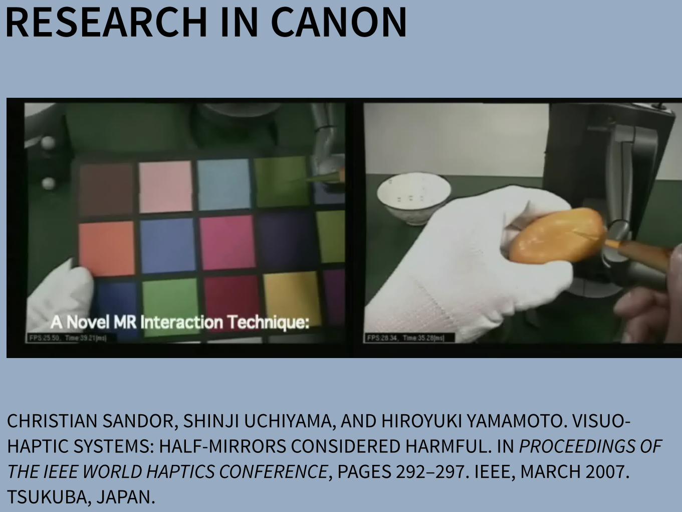
RESEARCH IN CANON
CHRISTIAN SANDOR, SHINJI UCHIYAMA, AND HIROYUKI YAMAMOTO. VISUO-HAPTIC SYSTEMS: HALF-MIRRORS CONSIDERED HARMFUL. IN PROCEEDINGS OF THE IEEE WORLD HAPTICS CONFERENCE, PAGES 292–297. IEEE, MARCH 2007. TSUKUBA, JAPAN.


LARGE SCALE HAPTICS DISPLAY AT NAIST (UNPUBLISHED)

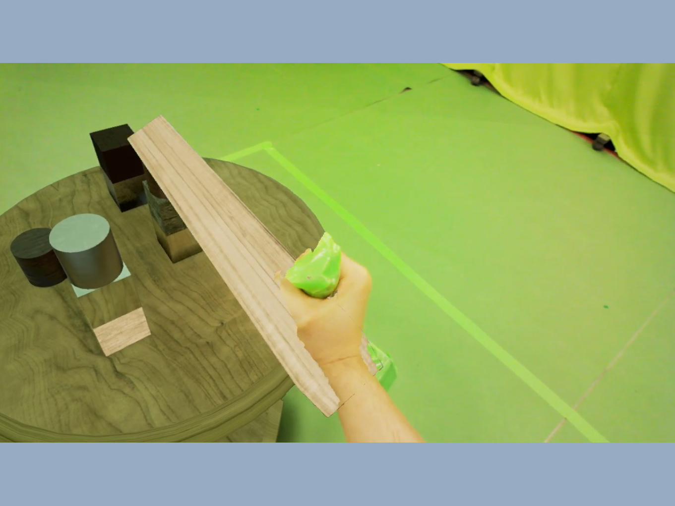
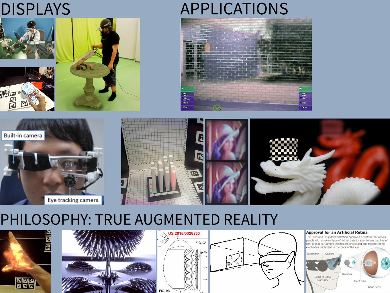
DISPLAYS APPLICATIONSSharpView: Improved Clarity of Defocused Content on OpticalSee-Through Head-Mounted Displays
Kohei Oshima⇤ † Kenneth R Moser⇤ ‡ Damien Constantine Rompapas† J. Edward Swan II‡ Sei Ikeda§
Goshiro Yamamoto† Takafumi Taketomi† Christian Sandor† Hirokazu Kato†
†Interactive Media Design LaboratoryNara Institute of Science and Technology
‡Computer Science & EngineeringMississippi State University
§Mobile Computing LaboratoryRitsumeikan University
(a) (b) (c) (d) (e)
Figure 1: The cause and effect of focus blur in Optical See-Through (OST) Head-Mounted Display (HMD) systems. (a) A user wearing the OSTHMD and related hardware used in our study. (b) Simplified schematic of an OST AR system. Blurring occurs when the virtual display screenand real world imagery are viewed at unequal focal distances. (c), (d), (e): Views through an OST Augmented Reality system, where the realworld image (c) is in focus, causing the virtual image (d) to appear blurred; (e) an improved virtual image after application of SharpView.
ABSTRACT
Augmented Reality (AR) systems, which utilize optical see-throughhead-mounted displays, are becoming more common place, withseveral consumer level options already available, and the promise ofadditional, more advanced, devices on the horizon. A common fac-tor among current generation optical see-through devices, though,is fixed focal distance to virtual content. While fixed focus is not aconcern for video see-through AR, since both virtual and real worldimagery are combined into a single image by the display, unequaldistances between real world objects and the virtual display screenin optical see-through AR is unavoidable.
In this work, we investigate the issue of focus blur, in particular,the blurring caused by simultaneously viewing virtual content andphysical objects in the environment at differing focal distances. Weadditionally examine the application of dynamic sharpening filtersas a straight forward, system independent, means for mitigating thiseffect improving the clarity of defocused AR content. We assess theutility of this method, termed SharpView, by employing an adjust-ment experiment in which users actively apply varying amounts ofsharpening to reduce the perception of blur in AR content shown atfour focal disparity levels relative to real world imagery.
Our experimental results confirm that dynamic correctionschemes are required for adequately addressing the presence of blurin Optical See-Through AR. Furthermore, we validate the ability ofour SharpView model to improve the perceived visual clarity of fo-cus blurred content, with optimal performance at focal differenceswell suited for near field AR applications.
Index Terms: H.5.1 [Information Interfaces and Presentation]:
⇤These authors contributed equally.†e-mail: {oshima.kohei.of0, damien.rompapas.dk1, goshiro, takafumi-t,
sandor, kato} @is.naist.jp‡e-mail: [email protected], [email protected]§e-mail: [email protected]
Multimedia Information Systems—Artificial, augmented, and vir-tual realities; I.4.4 [Image Processing and Computer Vision]:Restoration—Wiener filtering
1 INTRODUCTION
Optical See-Through (OST) Head-Mounted Displays (HMDs) haveseen an increase in both popularity and accessibility with the re-lease of several consumer level options, including Google Glassand Epson Moverio BT-200, and announced future offerings, suchas Microsoft’s HoloLens, on the horizon. The transparent displaytechnology used in these HMDs affords a unique experience, allow-ing the user to view on-screen computer generated (CG) contentwhile maintaining a direct view of their environment, a propertyextremely well suited for augmented reality (AR) systems. Un-fortunately, the current generation of consumer-level OST HMDsare only capable of presenting CG content at a single fixed focaldistance. This inherent limitation becomes problematic as the userattempts to simultaneously view the world and CG objects together,inducing focal rivalry as the eye’s optical system must continuouslyadjust to accommodate both the real and virtual items.
Figure 1 (a) and (b) illustrate an OST AR system in which a userconcurrently observes real and CG images at disparate distances.As the eye’s accommodation changes to match the focal distance ofthe real image, Figure 1 (c), the on-screen image appears blurred,Figure 1 (d). Naturally, the amount of blur perceived is directly re-lated to accommodative ability, which varies from person to personand undergoes further changes with age. The majority of individ-uals experience steady decline in accommodative ability betweenchild and adulthood [8], with more rapid decreases beginning toonset between 40–50, and general loss of sensitivity to focal dif-ferences occurring beyond 60 years of age. In order to effectivelyaddress such a wide variance in focal ability across users, flexiblecorrective measures, adaptable to specific user needs, are required.
Prior studies have proposed techniques for directly improvingthe distortion effects caused by the optical combiners within OSTHMDs [16]. However, optical distortion from device specific com-ponents only contributes a constant error. Other prior work has ap-plied image filtering and masking algorithms to video see-through
SharpView: Improved Clarity of Defocused Content on OpticalSee-Through Head-Mounted Displays
Kohei Oshima⇤ † Kenneth R Moser⇤ ‡ Damien Constantine Rompapas† J. Edward Swan II‡ Sei Ikeda§
Goshiro Yamamoto† Takafumi Taketomi† Christian Sandor† Hirokazu Kato†
†Interactive Media Design LaboratoryNara Institute of Science and Technology
‡Computer Science & EngineeringMississippi State University
§Mobile Computing LaboratoryRitsumeikan University
(a) (b) (c) (d) (e)
Figure 1: The cause and effect of focus blur in Optical See-Through (OST) Head-Mounted Display (HMD) systems. (a) A user wearing the OSTHMD and related hardware used in our study. (b) Simplified schematic of an OST AR system. Blurring occurs when the virtual display screenand real world imagery are viewed at unequal focal distances. (c), (d), (e): Views through an OST Augmented Reality system, where the realworld image (c) is in focus, causing the virtual image (d) to appear blurred; (e) an improved virtual image after application of SharpView.
ABSTRACT
Augmented Reality (AR) systems, which utilize optical see-throughhead-mounted displays, are becoming more common place, withseveral consumer level options already available, and the promise ofadditional, more advanced, devices on the horizon. A common fac-tor among current generation optical see-through devices, though,is fixed focal distance to virtual content. While fixed focus is not aconcern for video see-through AR, since both virtual and real worldimagery are combined into a single image by the display, unequaldistances between real world objects and the virtual display screenin optical see-through AR is unavoidable.
In this work, we investigate the issue of focus blur, in particular,the blurring caused by simultaneously viewing virtual content andphysical objects in the environment at differing focal distances. Weadditionally examine the application of dynamic sharpening filtersas a straight forward, system independent, means for mitigating thiseffect improving the clarity of defocused AR content. We assess theutility of this method, termed SharpView, by employing an adjust-ment experiment in which users actively apply varying amounts ofsharpening to reduce the perception of blur in AR content shown atfour focal disparity levels relative to real world imagery.
Our experimental results confirm that dynamic correctionschemes are required for adequately addressing the presence of blurin Optical See-Through AR. Furthermore, we validate the ability ofour SharpView model to improve the perceived visual clarity of fo-cus blurred content, with optimal performance at focal differenceswell suited for near field AR applications.
Index Terms: H.5.1 [Information Interfaces and Presentation]:
⇤These authors contributed equally.†e-mail: {oshima.kohei.of0, damien.rompapas.dk1, goshiro, takafumi-t,
sandor, kato} @is.naist.jp‡e-mail: [email protected], [email protected]§e-mail: [email protected]
Multimedia Information Systems—Artificial, augmented, and vir-tual realities; I.4.4 [Image Processing and Computer Vision]:Restoration—Wiener filtering
1 INTRODUCTION
Optical See-Through (OST) Head-Mounted Displays (HMDs) haveseen an increase in both popularity and accessibility with the re-lease of several consumer level options, including Google Glassand Epson Moverio BT-200, and announced future offerings, suchas Microsoft’s HoloLens, on the horizon. The transparent displaytechnology used in these HMDs affords a unique experience, allow-ing the user to view on-screen computer generated (CG) contentwhile maintaining a direct view of their environment, a propertyextremely well suited for augmented reality (AR) systems. Un-fortunately, the current generation of consumer-level OST HMDsare only capable of presenting CG content at a single fixed focaldistance. This inherent limitation becomes problematic as the userattempts to simultaneously view the world and CG objects together,inducing focal rivalry as the eye’s optical system must continuouslyadjust to accommodate both the real and virtual items.
Figure 1 (a) and (b) illustrate an OST AR system in which a userconcurrently observes real and CG images at disparate distances.As the eye’s accommodation changes to match the focal distance ofthe real image, Figure 1 (c), the on-screen image appears blurred,Figure 1 (d). Naturally, the amount of blur perceived is directly re-lated to accommodative ability, which varies from person to personand undergoes further changes with age. The majority of individ-uals experience steady decline in accommodative ability betweenchild and adulthood [8], with more rapid decreases beginning toonset between 40–50, and general loss of sensitivity to focal dif-ferences occurring beyond 60 years of age. In order to effectivelyaddress such a wide variance in focal ability across users, flexiblecorrective measures, adaptable to specific user needs, are required.
Prior studies have proposed techniques for directly improvingthe distortion effects caused by the optical combiners within OSTHMDs [16]. However, optical distortion from device specific com-ponents only contributes a constant error. Other prior work has ap-plied image filtering and masking algorithms to video see-through
Subjective Evaluation of a Semi-Automatic Optical See-ThroughHead-Mounted Display Calibration Technique
Kenneth Moser, Student Member, IEEE, Yuta Itoh, Student Member, IEEE, Kohei Oshima, Student Member, IEEE,J. Edward Swan II, Member, IEEE, Gudrun Klinker, Member, IEEE, and Christian Sandor, Member, IEEE
Fig. 1. Experimental hardware and design. (a) Display and camera system. (b) Task layout. (c) Pillars task. (d) Cubes task.
Abstract— With the growing availability of optical see-through (OST) head-mounted displays (HMDs), there is a present need forrobust, uncomplicated, and automatic calibration methods suited for non-expert users. This work presents the results of a user studywhich both objectively and subjectively examines registration accuracy produced by three OST HMD calibration methods: (1) SPAAM,(2) Degraded SPAAM, and (3) Recycled INDICA, a recently developed semi-automatic calibration method. Accuracy metrics usedfor evaluation include subject provided quality values and error between perceived and absolute registration coordinates. Our resultsshow all three calibration methods produce very accurate registration in the horizontal direction but caused subjects to perceive thedistance of virtual objects to be closer than intended. Surprisingly, the semi-automatic calibration method produced more accurateregistration vertically and in perceived object distance overall. User assessed quality values were also the highest for RecycledINDICA, particularly when objects were shown at distance. The results of this study confirm that Recycled INDICA is capable ofproducing equal or superior on-screen registration compared to common OST HMD calibration methods. We also identify a potentialhazard in using reprojection error as a quantitative analysis technique to predict registration accuracy. We conclude with discussingthe further need for examining INDICA calibration in binocular HMD systems, and the present possibility for creation of a closed-loopcontinuous calibration method for OST Augmented Reality.
Index Terms—Calibration, user study, OST HMD, INDICA, SPAAM, eye tracking
1 INTRODUCTION
Optical see-through (OST) augmented reality (AR) systems allow theoverlay of visual information onto a user’s view of the real world. Theprimary benefit of these systems, specifically in conjunction with headmounted display (HMD) hardware, is the ability of the user to maintaina view of the real environment from the perspective of their own eyes.This is in contrast to video see-through (VST) AR systems, in whichusers view the environment from the perspective of a camera. Al-
• Kenneth Moser is with the Department of Computer Science andEngineering at Mississippi State University. E-mail: [email protected]
• Yuta Itoh is with the Department of Informatics at Technical University ofMunich. E-mail: [email protected].
• Kohei Oshima is with the Interactive Media Design Lab in the Departmentof Information Science at Nara Institute of Science and Technology.E-mail: [email protected].
• J. Edward Swan II is with the Department of Computer Science atMississippi State University. E-mail: [email protected].
• Gudrun Klinker is with the Department of Informatics at TechnicalUniversity of Munich. E-mail: [email protected].
• Christian Sandor is with the Interactive Media Design Lab in theDepartment of Information Science at Nara Institute of Science andTechnology. E-mail: [email protected].
Manuscript received 18 Sept. 2014; accepted 10 Jan. 2015. Date ofPublication 20 Jan. 2015; date of current version 23 Mar. 2015.For information on obtaining reprints of this article, please sende-mail to: [email protected].
lowing a continuous hands-free view of the environment also lessenssafety concerns from visibility loss due to hardware malfunction, asis the case in military AR usage [20], where constant sight is of theutmost importance. The utility of both OST and VST AR is furtherenhanced when the location of on-screen information is used to pro-vide additional meaning and context.
In both VST and OST AR, information is fundamentally displayedin one of two reference frames: Screen Space and World Space. Infor-mation shown within screen space is statically positioned and does notappear displayed relative to any particular location or object withinthe world. This type of presentation is common in applications fa-cilitating manufacturing or assembly style tasks where the AR visualcomponents list instruction sets or other environment independent in-formation [4]. On-screen items rendered within world space appearto have a 3D position within the environment and are registered, dis-played relative, to fixed locations or objects. This display method re-quires sufficiently accurate registration between on-screen geometryand the visible environment in order to be effective [19]. Achieving anadequate level of world space registration accuracy requires the effec-tual employment of calibration mechanisms.
The goal of OST HMD calibration is to model the virtual cameraprojection matrix, used to render virtual geometry, such that it closelymatches the real viewing frustum created by the user’s eye and thedisplay optics. Unlike VST AR, where computer vision techniquesare used to correct registration [10, 16, 17], calibration of OST AR isnot straightforward. VST techniques are difficult or impossible to usefor correction in OST displays since the “camera” in these systems is
IEEE TRANSACTIONS ON VISUALIZATION AND COMPUTER GRAPHICS, VOL. 21, NO. ,491 4 APRIL��2015
Digital Object Identifier 10.1109/TVCG.2015.23918 6
1077-2626! 201 IEEE. Personal use is permitted, but republication/redistribution requires IEEE permission.See http://www.ieee.org/publications_standards/publications/rights/index.html for more information.
5�� � � � � �
5
PHILOSOPHY: TRUE AUGMENTED REALITY
There have been a number of shape displays based on pin architecture. The FEELEX project [14] was one of the early attempts to design combined shapes and computer graphics displays that can be explored by touch. FEELEX consisted of several mechanical pistons actuated by motors and cov-ered by a soft silicon surface. The images were projected onto its surface and synchronized with the movement of the pistons, creating simple shapes.
Lumen [32] is a low resolution, 13 by 13-pixel, bit-map display where each pixel can also physically move up and down (Figure 4). The resulting display can present both 2D graphic images and moving physical shapes that can be observed, touched, and felt with the hands. The 2D position sensor built into the surface of Lumen allows users to input commands and manipulate shapes with their hands.
Other related project are PopUp and Glowbits devices [18, 33]. PopUp consists of an array of rods that can be moved up and down using shape memory alloy actuators. The PopUp, however, does not have a visual and interactive component. Glowbits by Daniel Hirschmann (Figure 3) is a 2D array of rods with attached LEDs; the motorized rods can move up and down and LEDs can change their colors.
Discussion We have overviews a number of reasons why actuation can be used in user interfaces. We summarize them in Table 1.
Applications Examples
Aesthetics Automata, ambient displays, shape displays
Information communication
Ambient displays, haptic displays, shape displays
Mechanical work Robots
Controls—data consistency
Actuated tangibles
People-to-people communication
Haptic displays
Table 1: Applications of actuation in user interfaces
Most of the actual devices potentially span more then one application area and it seems that there is a lot of room for innovation and using some of the actuated interfaces in new application areas. For examples, robots could be used for information communication and ambient displays could be used for people-to-people communication.
Future research in actuated interfaces might attempt to sys-tematically investigate applications of actuated devices for various applications, some if which are perhaps not listed above. In the next section we provide analysis of shape dis-plays and there possible applications.
Figure 3: Shape displays (from top): Protrude, Flow,
Snoil, Aegis Hyposurface, Glowbits
2.1 Runtime Environments for User Interfaces in Ubiquitous Augmented Reality
Figure 2.7: Hand-fixed reference frame: Augmentations move with the hand of the user. Thisexample shows a user discussing a virtual map with another user. To observe themap from di↵erent angles, he can pick it up from the body-fixed toolchest aroundhis belt and put it in his hand.
Figure 2.8: Head-fixed reference frame: Augmentations move with the head gaze of the user.The example shows a map of the environment that supports a navigational task.
A Software Toolkit and Authoring Tools for User Interfaces in Ubiquitous Augmented Reality 21
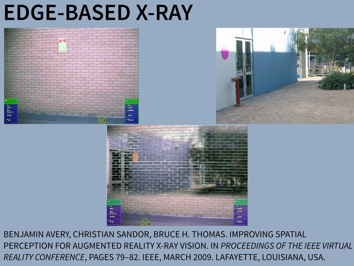
EDGE-BASED X-RAY
BENJAMIN AVERY, CHRISTIAN SANDOR, BRUCE H. THOMAS. IMPROVING SPATIAL PERCEPTION FOR AUGMENTED REALITY X-RAY VISION. IN PROCEEDINGS OF THE IEEE VIRTUAL REALITY CONFERENCE, PAGES 79–82. IEEE, MARCH 2009. LAFAYETTE, LOUISIANA, USA.


SALIENCY X-RAY
CHRISTIAN SANDOR, ANDREW CUNNINGHAM, ARINDAM DEY, AND VILLE-VEIKKO MATTILA. AN AUGMENTED REALITY X-RAY SYSTEM BASED ON VISUAL SALIENCY. IN PROCEEDINGS OF THE IEEE INTERNATIONAL SYMPOSIUM ON MIXED AND AUGMENTED REALITY, PAGES 27–36, SEOUL, KOREA, OCTOBER 2010.
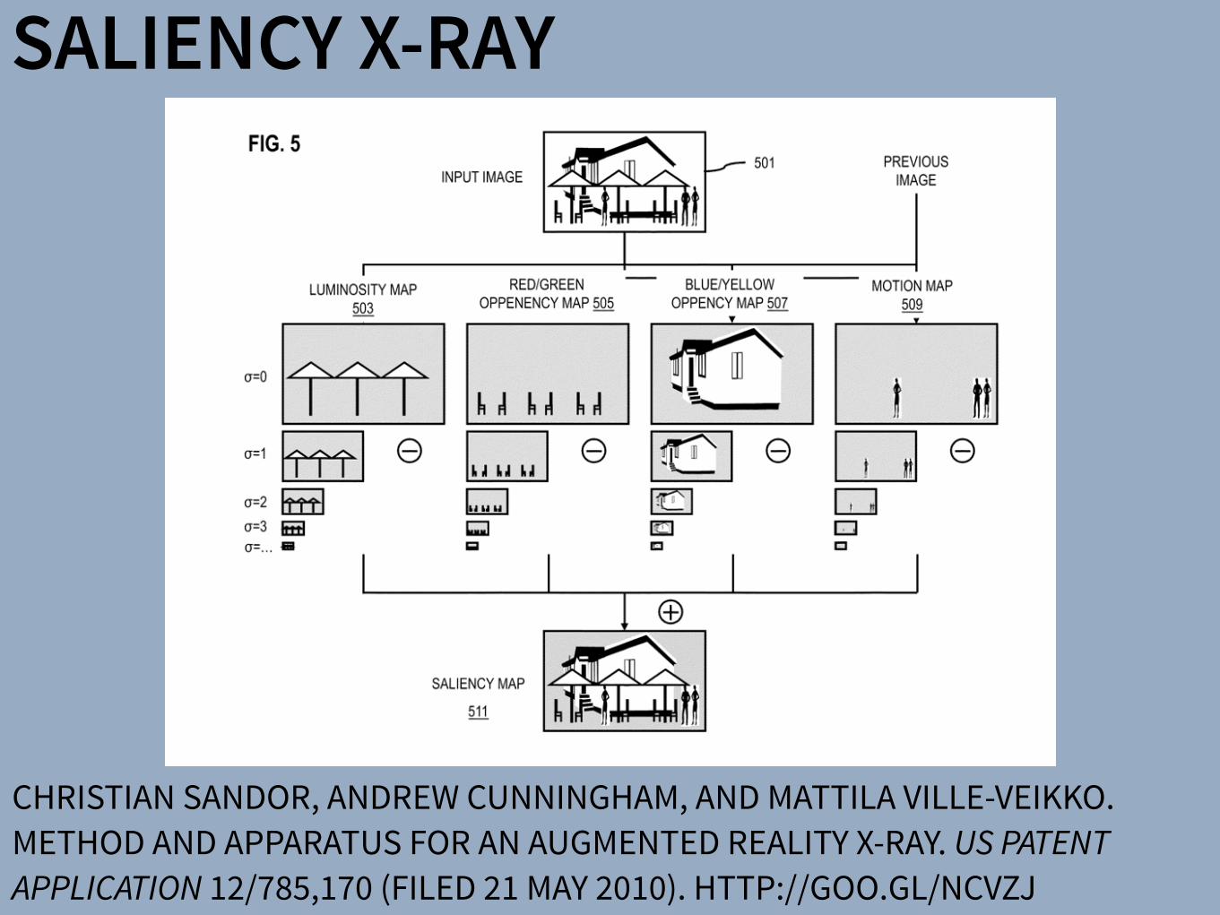
SALIENCY X-RAY
CHRISTIAN SANDOR, ANDREW CUNNINGHAM, AND MATTILA VILLE-VEIKKO. METHOD AND APPARATUS FOR AN AUGMENTED REALITY X-RAY. US PATENT APPLICATION 12/785,170 (FILED 21 MAY 2010). HTTP://GOO.GL/NCVZJ

MELTING
CHRISTIAN SANDOR, ANDREW CUNNINGHAM, ULRICH ECK, DONALD URQUHART, GRAEME JARVIS, ARINDAM DEY, SEBASTIEN BARBIER, MICHAEL R. MARNER, SANG RHEE. EGOCENTRIC SPACE-DISTORTING VISUALIZATIONS FOR RAPID ENVIRONMENT EXPLORATION IN MOBILE MIXED REALITY. IN PROCEEDINGS OF THE IEEE VIRTUAL REALITY CONFERENCE, PAGES 47–50, WALTHAM, MA, USA, MARCH 2010.
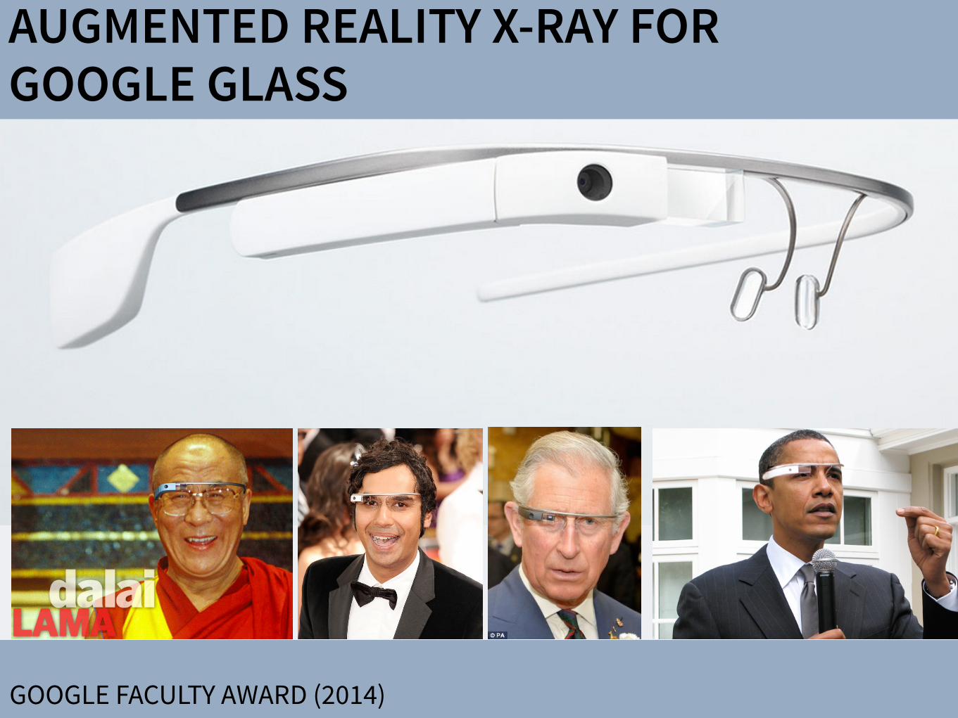
AUGMENTED REALITY X-RAY FOR GOOGLE GLASS
GOOGLE FACULTY AWARD (2014)

DEMO AT SIGGRAPH ASIA (12/2014)

FINAL DEMO (4/2015)
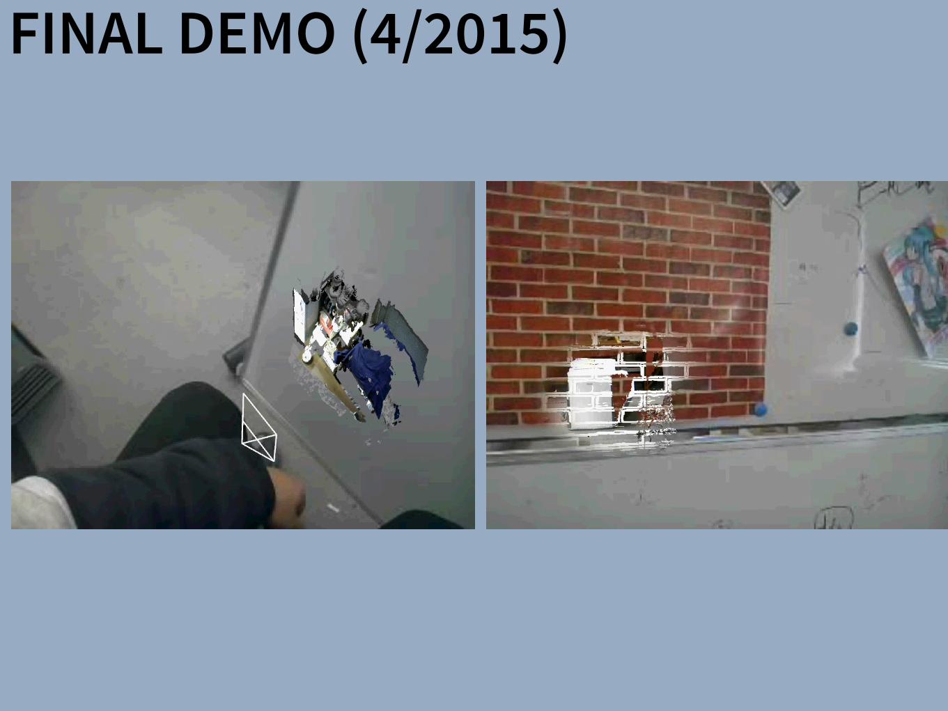
FINAL DEMO (4/2015)

Locations: Worcester – Gold Start Blv. 508-856-9510, Back to Work Center 508-854-2426, Worcester Medical Center 508- 368-3143 J Westboro 508-871-0789 J Leominster 978-840-1900 J Charlton 508-248-4141
Disclaimer: If you experience pain or worsening of symptoms call doctors office and stop doing your exercises. Internet Access: www.fallonclinic.org Click on Medical Services, Specialty Care, Rehabilitation, Informative Exercise Sheets
Rehabilitation & Sports Medicine Frozen Shoulder
SHOULDER - 26 Range of Motion Exercises: Pendulum (Circular) Let arm move in a circle clockwise, then counter- clockwise, by rocking body weight in a circular pattern. Repeat 10 times. Do 3-5 sessions per day.
SHOULDER - 7 Range of Motion Exercises (Self-Stretching Activities): Flexion Sitting upright, slide forearm forward along table, bending from waist until a stretch is felt. Hold 30 seconds. Repeat 1-4 times Do 1 session per day.
SHOULDER - 11 Range of Motion Exercises (Self-Stretching Activities): External Rotation (alternate) Keep palm of hand against door frame, and elbow bent at 90°. Turn body from fixed hand until a stretch is felt. Hold 30 seconds. Repeat 1-4 times Do 1 session per day.
SHOULDER - 9 Range of Motion Exercises (Self-Stretching Activities): Abduction With arm resting on table, palm up, bring head down toward arm and simultaneously move trunk away from table. Hold 30 seconds. Repeat 1-4 times Do 1 session per day.
SHOULDER - 73 Towel Stretch for Internal Rotation Pull involved arm up behind back by pulling towel upward with other arm. Hold 30 seconds. Repeat 1-4 times Do 1 session per day.
SCAP SETS Pull your shoulders back, pinching the shoulder blades together. Do not let the shoulders come forward. Hold 5-10 seconds. Repeat 10 times Do 1 session per day.
FUTURE WORK: MEDICAL APPLICATIONS

FUTURE WORK: MEDICAL APPLICATIONS
COURTESY OF HTTP://CAMPAR.IN.TUM.DE/MAIN/FELIXBORK

DISPLAYS APPLICATIONSSharpView: Improved Clarity of Defocused Content on OpticalSee-Through Head-Mounted Displays
Kohei Oshima⇤ † Kenneth R Moser⇤ ‡ Damien Constantine Rompapas† J. Edward Swan II‡ Sei Ikeda§
Goshiro Yamamoto† Takafumi Taketomi† Christian Sandor† Hirokazu Kato†
†Interactive Media Design LaboratoryNara Institute of Science and Technology
‡Computer Science & EngineeringMississippi State University
§Mobile Computing LaboratoryRitsumeikan University
(a) (b) (c) (d) (e)
Figure 1: The cause and effect of focus blur in Optical See-Through (OST) Head-Mounted Display (HMD) systems. (a) A user wearing the OSTHMD and related hardware used in our study. (b) Simplified schematic of an OST AR system. Blurring occurs when the virtual display screenand real world imagery are viewed at unequal focal distances. (c), (d), (e): Views through an OST Augmented Reality system, where the realworld image (c) is in focus, causing the virtual image (d) to appear blurred; (e) an improved virtual image after application of SharpView.
ABSTRACT
Augmented Reality (AR) systems, which utilize optical see-throughhead-mounted displays, are becoming more common place, withseveral consumer level options already available, and the promise ofadditional, more advanced, devices on the horizon. A common fac-tor among current generation optical see-through devices, though,is fixed focal distance to virtual content. While fixed focus is not aconcern for video see-through AR, since both virtual and real worldimagery are combined into a single image by the display, unequaldistances between real world objects and the virtual display screenin optical see-through AR is unavoidable.
In this work, we investigate the issue of focus blur, in particular,the blurring caused by simultaneously viewing virtual content andphysical objects in the environment at differing focal distances. Weadditionally examine the application of dynamic sharpening filtersas a straight forward, system independent, means for mitigating thiseffect improving the clarity of defocused AR content. We assess theutility of this method, termed SharpView, by employing an adjust-ment experiment in which users actively apply varying amounts ofsharpening to reduce the perception of blur in AR content shown atfour focal disparity levels relative to real world imagery.
Our experimental results confirm that dynamic correctionschemes are required for adequately addressing the presence of blurin Optical See-Through AR. Furthermore, we validate the ability ofour SharpView model to improve the perceived visual clarity of fo-cus blurred content, with optimal performance at focal differenceswell suited for near field AR applications.
Index Terms: H.5.1 [Information Interfaces and Presentation]:
⇤These authors contributed equally.†e-mail: {oshima.kohei.of0, damien.rompapas.dk1, goshiro, takafumi-t,
sandor, kato} @is.naist.jp‡e-mail: [email protected], [email protected]§e-mail: [email protected]
Multimedia Information Systems—Artificial, augmented, and vir-tual realities; I.4.4 [Image Processing and Computer Vision]:Restoration—Wiener filtering
1 INTRODUCTION
Optical See-Through (OST) Head-Mounted Displays (HMDs) haveseen an increase in both popularity and accessibility with the re-lease of several consumer level options, including Google Glassand Epson Moverio BT-200, and announced future offerings, suchas Microsoft’s HoloLens, on the horizon. The transparent displaytechnology used in these HMDs affords a unique experience, allow-ing the user to view on-screen computer generated (CG) contentwhile maintaining a direct view of their environment, a propertyextremely well suited for augmented reality (AR) systems. Un-fortunately, the current generation of consumer-level OST HMDsare only capable of presenting CG content at a single fixed focaldistance. This inherent limitation becomes problematic as the userattempts to simultaneously view the world and CG objects together,inducing focal rivalry as the eye’s optical system must continuouslyadjust to accommodate both the real and virtual items.
Figure 1 (a) and (b) illustrate an OST AR system in which a userconcurrently observes real and CG images at disparate distances.As the eye’s accommodation changes to match the focal distance ofthe real image, Figure 1 (c), the on-screen image appears blurred,Figure 1 (d). Naturally, the amount of blur perceived is directly re-lated to accommodative ability, which varies from person to personand undergoes further changes with age. The majority of individ-uals experience steady decline in accommodative ability betweenchild and adulthood [8], with more rapid decreases beginning toonset between 40–50, and general loss of sensitivity to focal dif-ferences occurring beyond 60 years of age. In order to effectivelyaddress such a wide variance in focal ability across users, flexiblecorrective measures, adaptable to specific user needs, are required.
Prior studies have proposed techniques for directly improvingthe distortion effects caused by the optical combiners within OSTHMDs [16]. However, optical distortion from device specific com-ponents only contributes a constant error. Other prior work has ap-plied image filtering and masking algorithms to video see-through
SharpView: Improved Clarity of Defocused Content on OpticalSee-Through Head-Mounted Displays
Kohei Oshima⇤ † Kenneth R Moser⇤ ‡ Damien Constantine Rompapas† J. Edward Swan II‡ Sei Ikeda§
Goshiro Yamamoto† Takafumi Taketomi† Christian Sandor† Hirokazu Kato†
†Interactive Media Design LaboratoryNara Institute of Science and Technology
‡Computer Science & EngineeringMississippi State University
§Mobile Computing LaboratoryRitsumeikan University
(a) (b) (c) (d) (e)
Figure 1: The cause and effect of focus blur in Optical See-Through (OST) Head-Mounted Display (HMD) systems. (a) A user wearing the OSTHMD and related hardware used in our study. (b) Simplified schematic of an OST AR system. Blurring occurs when the virtual display screenand real world imagery are viewed at unequal focal distances. (c), (d), (e): Views through an OST Augmented Reality system, where the realworld image (c) is in focus, causing the virtual image (d) to appear blurred; (e) an improved virtual image after application of SharpView.
ABSTRACT
Augmented Reality (AR) systems, which utilize optical see-throughhead-mounted displays, are becoming more common place, withseveral consumer level options already available, and the promise ofadditional, more advanced, devices on the horizon. A common fac-tor among current generation optical see-through devices, though,is fixed focal distance to virtual content. While fixed focus is not aconcern for video see-through AR, since both virtual and real worldimagery are combined into a single image by the display, unequaldistances between real world objects and the virtual display screenin optical see-through AR is unavoidable.
In this work, we investigate the issue of focus blur, in particular,the blurring caused by simultaneously viewing virtual content andphysical objects in the environment at differing focal distances. Weadditionally examine the application of dynamic sharpening filtersas a straight forward, system independent, means for mitigating thiseffect improving the clarity of defocused AR content. We assess theutility of this method, termed SharpView, by employing an adjust-ment experiment in which users actively apply varying amounts ofsharpening to reduce the perception of blur in AR content shown atfour focal disparity levels relative to real world imagery.
Our experimental results confirm that dynamic correctionschemes are required for adequately addressing the presence of blurin Optical See-Through AR. Furthermore, we validate the ability ofour SharpView model to improve the perceived visual clarity of fo-cus blurred content, with optimal performance at focal differenceswell suited for near field AR applications.
Index Terms: H.5.1 [Information Interfaces and Presentation]:
⇤These authors contributed equally.†e-mail: {oshima.kohei.of0, damien.rompapas.dk1, goshiro, takafumi-t,
sandor, kato} @is.naist.jp‡e-mail: [email protected], [email protected]§e-mail: [email protected]
Multimedia Information Systems—Artificial, augmented, and vir-tual realities; I.4.4 [Image Processing and Computer Vision]:Restoration—Wiener filtering
1 INTRODUCTION
Optical See-Through (OST) Head-Mounted Displays (HMDs) haveseen an increase in both popularity and accessibility with the re-lease of several consumer level options, including Google Glassand Epson Moverio BT-200, and announced future offerings, suchas Microsoft’s HoloLens, on the horizon. The transparent displaytechnology used in these HMDs affords a unique experience, allow-ing the user to view on-screen computer generated (CG) contentwhile maintaining a direct view of their environment, a propertyextremely well suited for augmented reality (AR) systems. Un-fortunately, the current generation of consumer-level OST HMDsare only capable of presenting CG content at a single fixed focaldistance. This inherent limitation becomes problematic as the userattempts to simultaneously view the world and CG objects together,inducing focal rivalry as the eye’s optical system must continuouslyadjust to accommodate both the real and virtual items.
Figure 1 (a) and (b) illustrate an OST AR system in which a userconcurrently observes real and CG images at disparate distances.As the eye’s accommodation changes to match the focal distance ofthe real image, Figure 1 (c), the on-screen image appears blurred,Figure 1 (d). Naturally, the amount of blur perceived is directly re-lated to accommodative ability, which varies from person to personand undergoes further changes with age. The majority of individ-uals experience steady decline in accommodative ability betweenchild and adulthood [8], with more rapid decreases beginning toonset between 40–50, and general loss of sensitivity to focal dif-ferences occurring beyond 60 years of age. In order to effectivelyaddress such a wide variance in focal ability across users, flexiblecorrective measures, adaptable to specific user needs, are required.
Prior studies have proposed techniques for directly improvingthe distortion effects caused by the optical combiners within OSTHMDs [16]. However, optical distortion from device specific com-ponents only contributes a constant error. Other prior work has ap-plied image filtering and masking algorithms to video see-through
SharpView: Improved Clarity of Defocused Content on OpticalSee-Through Head-Mounted Displays
Kohei Oshima⇤ † Kenneth R Moser⇤ ‡ Damien Constantine Rompapas† J. Edward Swan II‡ Sei Ikeda§
Goshiro Yamamoto† Takafumi Taketomi† Christian Sandor† Hirokazu Kato†
†Interactive Media Design LaboratoryNara Institute of Science and Technology
‡Computer Science & EngineeringMississippi State University
§Mobile Computing LaboratoryRitsumeikan University
(a) (b) (c) (d) (e)
Figure 1: The cause and effect of focus blur in Optical See-Through (OST) Head-Mounted Display (HMD) systems. (a) A user wearing the OSTHMD and related hardware used in our study. (b) Simplified schematic of an OST AR system. Blurring occurs when the virtual display screenand real world imagery are viewed at unequal focal distances. (c), (d), (e): Views through an OST Augmented Reality system, where the realworld image (c) is in focus, causing the virtual image (d) to appear blurred; (e) an improved virtual image after application of SharpView.
ABSTRACT
Augmented Reality (AR) systems, which utilize optical see-throughhead-mounted displays, are becoming more common place, withseveral consumer level options already available, and the promise ofadditional, more advanced, devices on the horizon. A common fac-tor among current generation optical see-through devices, though,is fixed focal distance to virtual content. While fixed focus is not aconcern for video see-through AR, since both virtual and real worldimagery are combined into a single image by the display, unequaldistances between real world objects and the virtual display screenin optical see-through AR is unavoidable.
In this work, we investigate the issue of focus blur, in particular,the blurring caused by simultaneously viewing virtual content andphysical objects in the environment at differing focal distances. Weadditionally examine the application of dynamic sharpening filtersas a straight forward, system independent, means for mitigating thiseffect improving the clarity of defocused AR content. We assess theutility of this method, termed SharpView, by employing an adjust-ment experiment in which users actively apply varying amounts ofsharpening to reduce the perception of blur in AR content shown atfour focal disparity levels relative to real world imagery.
Our experimental results confirm that dynamic correctionschemes are required for adequately addressing the presence of blurin Optical See-Through AR. Furthermore, we validate the ability ofour SharpView model to improve the perceived visual clarity of fo-cus blurred content, with optimal performance at focal differenceswell suited for near field AR applications.
Index Terms: H.5.1 [Information Interfaces and Presentation]:
⇤These authors contributed equally.†e-mail: {oshima.kohei.of0, damien.rompapas.dk1, goshiro, takafumi-t,
sandor, kato} @is.naist.jp‡e-mail: [email protected], [email protected]§e-mail: [email protected]
Multimedia Information Systems—Artificial, augmented, and vir-tual realities; I.4.4 [Image Processing and Computer Vision]:Restoration—Wiener filtering
1 INTRODUCTION
Optical See-Through (OST) Head-Mounted Displays (HMDs) haveseen an increase in both popularity and accessibility with the re-lease of several consumer level options, including Google Glassand Epson Moverio BT-200, and announced future offerings, suchas Microsoft’s HoloLens, on the horizon. The transparent displaytechnology used in these HMDs affords a unique experience, allow-ing the user to view on-screen computer generated (CG) contentwhile maintaining a direct view of their environment, a propertyextremely well suited for augmented reality (AR) systems. Un-fortunately, the current generation of consumer-level OST HMDsare only capable of presenting CG content at a single fixed focaldistance. This inherent limitation becomes problematic as the userattempts to simultaneously view the world and CG objects together,inducing focal rivalry as the eye’s optical system must continuouslyadjust to accommodate both the real and virtual items.
Figure 1 (a) and (b) illustrate an OST AR system in which a userconcurrently observes real and CG images at disparate distances.As the eye’s accommodation changes to match the focal distance ofthe real image, Figure 1 (c), the on-screen image appears blurred,Figure 1 (d). Naturally, the amount of blur perceived is directly re-lated to accommodative ability, which varies from person to personand undergoes further changes with age. The majority of individ-uals experience steady decline in accommodative ability betweenchild and adulthood [8], with more rapid decreases beginning toonset between 40–50, and general loss of sensitivity to focal dif-ferences occurring beyond 60 years of age. In order to effectivelyaddress such a wide variance in focal ability across users, flexiblecorrective measures, adaptable to specific user needs, are required.
Prior studies have proposed techniques for directly improvingthe distortion effects caused by the optical combiners within OSTHMDs [16]. However, optical distortion from device specific com-ponents only contributes a constant error. Other prior work has ap-plied image filtering and masking algorithms to video see-through
Subjective Evaluation of a Semi-Automatic Optical See-ThroughHead-Mounted Display Calibration Technique
Kenneth Moser, Student Member, IEEE, Yuta Itoh, Student Member, IEEE, Kohei Oshima, Student Member, IEEE,J. Edward Swan II, Member, IEEE, Gudrun Klinker, Member, IEEE, and Christian Sandor, Member, IEEE
Fig. 1. Experimental hardware and design. (a) Display and camera system. (b) Task layout. (c) Pillars task. (d) Cubes task.
Abstract— With the growing availability of optical see-through (OST) head-mounted displays (HMDs), there is a present need forrobust, uncomplicated, and automatic calibration methods suited for non-expert users. This work presents the results of a user studywhich both objectively and subjectively examines registration accuracy produced by three OST HMD calibration methods: (1) SPAAM,(2) Degraded SPAAM, and (3) Recycled INDICA, a recently developed semi-automatic calibration method. Accuracy metrics usedfor evaluation include subject provided quality values and error between perceived and absolute registration coordinates. Our resultsshow all three calibration methods produce very accurate registration in the horizontal direction but caused subjects to perceive thedistance of virtual objects to be closer than intended. Surprisingly, the semi-automatic calibration method produced more accurateregistration vertically and in perceived object distance overall. User assessed quality values were also the highest for RecycledINDICA, particularly when objects were shown at distance. The results of this study confirm that Recycled INDICA is capable ofproducing equal or superior on-screen registration compared to common OST HMD calibration methods. We also identify a potentialhazard in using reprojection error as a quantitative analysis technique to predict registration accuracy. We conclude with discussingthe further need for examining INDICA calibration in binocular HMD systems, and the present possibility for creation of a closed-loopcontinuous calibration method for OST Augmented Reality.
Index Terms—Calibration, user study, OST HMD, INDICA, SPAAM, eye tracking
1 INTRODUCTION
Optical see-through (OST) augmented reality (AR) systems allow theoverlay of visual information onto a user’s view of the real world. Theprimary benefit of these systems, specifically in conjunction with headmounted display (HMD) hardware, is the ability of the user to maintaina view of the real environment from the perspective of their own eyes.This is in contrast to video see-through (VST) AR systems, in whichusers view the environment from the perspective of a camera. Al-
• Kenneth Moser is with the Department of Computer Science andEngineering at Mississippi State University. E-mail: [email protected]
• Yuta Itoh is with the Department of Informatics at Technical University ofMunich. E-mail: [email protected].
• Kohei Oshima is with the Interactive Media Design Lab in the Departmentof Information Science at Nara Institute of Science and Technology.E-mail: [email protected].
• J. Edward Swan II is with the Department of Computer Science atMississippi State University. E-mail: [email protected].
• Gudrun Klinker is with the Department of Informatics at TechnicalUniversity of Munich. E-mail: [email protected].
• Christian Sandor is with the Interactive Media Design Lab in theDepartment of Information Science at Nara Institute of Science andTechnology. E-mail: [email protected].
Manuscript received 18 Sept. 2014; accepted 10 Jan. 2015. Date ofPublication 20 Jan. 2015; date of current version 23 Mar. 2015.For information on obtaining reprints of this article, please sende-mail to: [email protected].
lowing a continuous hands-free view of the environment also lessenssafety concerns from visibility loss due to hardware malfunction, asis the case in military AR usage [20], where constant sight is of theutmost importance. The utility of both OST and VST AR is furtherenhanced when the location of on-screen information is used to pro-vide additional meaning and context.
In both VST and OST AR, information is fundamentally displayedin one of two reference frames: Screen Space and World Space. Infor-mation shown within screen space is statically positioned and does notappear displayed relative to any particular location or object withinthe world. This type of presentation is common in applications fa-cilitating manufacturing or assembly style tasks where the AR visualcomponents list instruction sets or other environment independent in-formation [4]. On-screen items rendered within world space appearto have a 3D position within the environment and are registered, dis-played relative, to fixed locations or objects. This display method re-quires sufficiently accurate registration between on-screen geometryand the visible environment in order to be effective [19]. Achieving anadequate level of world space registration accuracy requires the effec-tual employment of calibration mechanisms.
The goal of OST HMD calibration is to model the virtual cameraprojection matrix, used to render virtual geometry, such that it closelymatches the real viewing frustum created by the user’s eye and thedisplay optics. Unlike VST AR, where computer vision techniquesare used to correct registration [10, 16, 17], calibration of OST AR isnot straightforward. VST techniques are difficult or impossible to usefor correction in OST displays since the “camera” in these systems is
IEEE TRANSACTIONS ON VISUALIZATION AND COMPUTER GRAPHICS, VOL. 21, NO. ,491 4 APRIL��2015
Digital Object Identifier 10.1109/TVCG.2015.23918 6
1077-2626! 201 IEEE. Personal use is permitted, but republication/redistribution requires IEEE permission.See http://www.ieee.org/publications_standards/publications/rights/index.html for more information.
5�� � � � � �
5
PHILOSOPHY: TRUE AUGMENTED REALITY
There have been a number of shape displays based on pin architecture. The FEELEX project [14] was one of the early attempts to design combined shapes and computer graphics displays that can be explored by touch. FEELEX consisted of several mechanical pistons actuated by motors and cov-ered by a soft silicon surface. The images were projected onto its surface and synchronized with the movement of the pistons, creating simple shapes.
Lumen [32] is a low resolution, 13 by 13-pixel, bit-map display where each pixel can also physically move up and down (Figure 4). The resulting display can present both 2D graphic images and moving physical shapes that can be observed, touched, and felt with the hands. The 2D position sensor built into the surface of Lumen allows users to input commands and manipulate shapes with their hands.
Other related project are PopUp and Glowbits devices [18, 33]. PopUp consists of an array of rods that can be moved up and down using shape memory alloy actuators. The PopUp, however, does not have a visual and interactive component. Glowbits by Daniel Hirschmann (Figure 3) is a 2D array of rods with attached LEDs; the motorized rods can move up and down and LEDs can change their colors.
Discussion We have overviews a number of reasons why actuation can be used in user interfaces. We summarize them in Table 1.
Applications Examples
Aesthetics Automata, ambient displays, shape displays
Information communication
Ambient displays, haptic displays, shape displays
Mechanical work Robots
Controls—data consistency
Actuated tangibles
People-to-people communication
Haptic displays
Table 1: Applications of actuation in user interfaces
Most of the actual devices potentially span more then one application area and it seems that there is a lot of room for innovation and using some of the actuated interfaces in new application areas. For examples, robots could be used for information communication and ambient displays could be used for people-to-people communication.
Future research in actuated interfaces might attempt to sys-tematically investigate applications of actuated devices for various applications, some if which are perhaps not listed above. In the next section we provide analysis of shape dis-plays and there possible applications.
Figure 3: Shape displays (from top): Protrude, Flow,
Snoil, Aegis Hyposurface, Glowbits
2.1 Runtime Environments for User Interfaces in Ubiquitous Augmented Reality
Figure 2.7: Hand-fixed reference frame: Augmentations move with the hand of the user. Thisexample shows a user discussing a virtual map with another user. To observe themap from di↵erent angles, he can pick it up from the body-fixed toolchest aroundhis belt and put it in his hand.
Figure 2.8: Head-fixed reference frame: Augmentations move with the head gaze of the user.The example shows a map of the environment that supports a navigational task.
A Software Toolkit and Authoring Tools for User Interfaces in Ubiquitous Augmented Reality 21

TRANSMEDIA CINEMATOGRAPHY
HTTPS://WWW.YOUTUBE.COM/WATCH?V=9JPWITVR0GA

Nurikabe Kappa
Tengu
Long neck woman
Big centipede
Mokumokuren
Nopperabou
Tsuchigumo
Nurarihyon
Paper umbrella haunted
UmibouzuGasyadokuro
YŌKAI

AR YŌKAI(UNPUBLISHED)

Nurikabe Kappa
Tengu
Long neck woman
Big centipede
Mokumokuren
Nopperabou
Nurikabe Kappa
Tengu
Long neck woman
Big centipede
Mokumokuren
Nopperabou

PHILOSOPHY: TRUE AUGMENTED REALITY
There have been a number of shape displays based on pin architecture. The FEELEX project [14] was one of the early attempts to design combined shapes and computer graphics displays that can be explored by touch. FEELEX consisted of several mechanical pistons actuated by motors and cov-ered by a soft silicon surface. The images were projected onto its surface and synchronized with the movement of the pistons, creating simple shapes.
Lumen [32] is a low resolution, 13 by 13-pixel, bit-map display where each pixel can also physically move up and down (Figure 4). The resulting display can present both 2D graphic images and moving physical shapes that can be observed, touched, and felt with the hands. The 2D position sensor built into the surface of Lumen allows users to input commands and manipulate shapes with their hands.
Other related project are PopUp and Glowbits devices [18, 33]. PopUp consists of an array of rods that can be moved up and down using shape memory alloy actuators. The PopUp, however, does not have a visual and interactive component. Glowbits by Daniel Hirschmann (Figure 3) is a 2D array of rods with attached LEDs; the motorized rods can move up and down and LEDs can change their colors.
Discussion We have overviews a number of reasons why actuation can be used in user interfaces. We summarize them in Table 1.
Applications Examples
Aesthetics Automata, ambient displays, shape displays
Information communication
Ambient displays, haptic displays, shape displays
Mechanical work Robots
Controls—data consistency
Actuated tangibles
People-to-people communication
Haptic displays
Table 1: Applications of actuation in user interfaces
Most of the actual devices potentially span more then one application area and it seems that there is a lot of room for innovation and using some of the actuated interfaces in new application areas. For examples, robots could be used for information communication and ambient displays could be used for people-to-people communication.
Future research in actuated interfaces might attempt to sys-tematically investigate applications of actuated devices for various applications, some if which are perhaps not listed above. In the next section we provide analysis of shape dis-plays and there possible applications.
Figure 3: Shape displays (from top): Protrude, Flow,
Snoil, Aegis Hyposurface, Glowbits
2.1 Runtime Environments for User Interfaces in Ubiquitous Augmented Reality
Figure 2.7: Hand-fixed reference frame: Augmentations move with the hand of the user. Thisexample shows a user discussing a virtual map with another user. To observe themap from di↵erent angles, he can pick it up from the body-fixed toolchest aroundhis belt and put it in his hand.
Figure 2.8: Head-fixed reference frame: Augmentations move with the head gaze of the user.The example shows a map of the environment that supports a navigational task.
A Software Toolkit and Authoring Tools for User Interfaces in Ubiquitous Augmented Reality 21
DISPLAYS APPLICATIONSSharpView: Improved Clarity of Defocused Content on OpticalSee-Through Head-Mounted Displays
Kohei Oshima⇤ † Kenneth R Moser⇤ ‡ Damien Constantine Rompapas† J. Edward Swan II‡ Sei Ikeda§
Goshiro Yamamoto† Takafumi Taketomi† Christian Sandor† Hirokazu Kato†
†Interactive Media Design LaboratoryNara Institute of Science and Technology
‡Computer Science & EngineeringMississippi State University
§Mobile Computing LaboratoryRitsumeikan University
(a) (b) (c) (d) (e)
Figure 1: The cause and effect of focus blur in Optical See-Through (OST) Head-Mounted Display (HMD) systems. (a) A user wearing the OSTHMD and related hardware used in our study. (b) Simplified schematic of an OST AR system. Blurring occurs when the virtual display screenand real world imagery are viewed at unequal focal distances. (c), (d), (e): Views through an OST Augmented Reality system, where the realworld image (c) is in focus, causing the virtual image (d) to appear blurred; (e) an improved virtual image after application of SharpView.
ABSTRACT
Augmented Reality (AR) systems, which utilize optical see-throughhead-mounted displays, are becoming more common place, withseveral consumer level options already available, and the promise ofadditional, more advanced, devices on the horizon. A common fac-tor among current generation optical see-through devices, though,is fixed focal distance to virtual content. While fixed focus is not aconcern for video see-through AR, since both virtual and real worldimagery are combined into a single image by the display, unequaldistances between real world objects and the virtual display screenin optical see-through AR is unavoidable.
In this work, we investigate the issue of focus blur, in particular,the blurring caused by simultaneously viewing virtual content andphysical objects in the environment at differing focal distances. Weadditionally examine the application of dynamic sharpening filtersas a straight forward, system independent, means for mitigating thiseffect improving the clarity of defocused AR content. We assess theutility of this method, termed SharpView, by employing an adjust-ment experiment in which users actively apply varying amounts ofsharpening to reduce the perception of blur in AR content shown atfour focal disparity levels relative to real world imagery.
Our experimental results confirm that dynamic correctionschemes are required for adequately addressing the presence of blurin Optical See-Through AR. Furthermore, we validate the ability ofour SharpView model to improve the perceived visual clarity of fo-cus blurred content, with optimal performance at focal differenceswell suited for near field AR applications.
Index Terms: H.5.1 [Information Interfaces and Presentation]:
⇤These authors contributed equally.†e-mail: {oshima.kohei.of0, damien.rompapas.dk1, goshiro, takafumi-t,
sandor, kato} @is.naist.jp‡e-mail: [email protected], [email protected]§e-mail: [email protected]
Multimedia Information Systems—Artificial, augmented, and vir-tual realities; I.4.4 [Image Processing and Computer Vision]:Restoration—Wiener filtering
1 INTRODUCTION
Optical See-Through (OST) Head-Mounted Displays (HMDs) haveseen an increase in both popularity and accessibility with the re-lease of several consumer level options, including Google Glassand Epson Moverio BT-200, and announced future offerings, suchas Microsoft’s HoloLens, on the horizon. The transparent displaytechnology used in these HMDs affords a unique experience, allow-ing the user to view on-screen computer generated (CG) contentwhile maintaining a direct view of their environment, a propertyextremely well suited for augmented reality (AR) systems. Un-fortunately, the current generation of consumer-level OST HMDsare only capable of presenting CG content at a single fixed focaldistance. This inherent limitation becomes problematic as the userattempts to simultaneously view the world and CG objects together,inducing focal rivalry as the eye’s optical system must continuouslyadjust to accommodate both the real and virtual items.
Figure 1 (a) and (b) illustrate an OST AR system in which a userconcurrently observes real and CG images at disparate distances.As the eye’s accommodation changes to match the focal distance ofthe real image, Figure 1 (c), the on-screen image appears blurred,Figure 1 (d). Naturally, the amount of blur perceived is directly re-lated to accommodative ability, which varies from person to personand undergoes further changes with age. The majority of individ-uals experience steady decline in accommodative ability betweenchild and adulthood [8], with more rapid decreases beginning toonset between 40–50, and general loss of sensitivity to focal dif-ferences occurring beyond 60 years of age. In order to effectivelyaddress such a wide variance in focal ability across users, flexiblecorrective measures, adaptable to specific user needs, are required.
Prior studies have proposed techniques for directly improvingthe distortion effects caused by the optical combiners within OSTHMDs [16]. However, optical distortion from device specific com-ponents only contributes a constant error. Other prior work has ap-plied image filtering and masking algorithms to video see-through
SharpView: Improved Clarity of Defocused Content on OpticalSee-Through Head-Mounted Displays
Kohei Oshima⇤ † Kenneth R Moser⇤ ‡ Damien Constantine Rompapas† J. Edward Swan II‡ Sei Ikeda§
Goshiro Yamamoto† Takafumi Taketomi† Christian Sandor† Hirokazu Kato†
†Interactive Media Design LaboratoryNara Institute of Science and Technology
‡Computer Science & EngineeringMississippi State University
§Mobile Computing LaboratoryRitsumeikan University
(a) (b) (c) (d) (e)
Figure 1: The cause and effect of focus blur in Optical See-Through (OST) Head-Mounted Display (HMD) systems. (a) A user wearing the OSTHMD and related hardware used in our study. (b) Simplified schematic of an OST AR system. Blurring occurs when the virtual display screenand real world imagery are viewed at unequal focal distances. (c), (d), (e): Views through an OST Augmented Reality system, where the realworld image (c) is in focus, causing the virtual image (d) to appear blurred; (e) an improved virtual image after application of SharpView.
ABSTRACT
Augmented Reality (AR) systems, which utilize optical see-throughhead-mounted displays, are becoming more common place, withseveral consumer level options already available, and the promise ofadditional, more advanced, devices on the horizon. A common fac-tor among current generation optical see-through devices, though,is fixed focal distance to virtual content. While fixed focus is not aconcern for video see-through AR, since both virtual and real worldimagery are combined into a single image by the display, unequaldistances between real world objects and the virtual display screenin optical see-through AR is unavoidable.
In this work, we investigate the issue of focus blur, in particular,the blurring caused by simultaneously viewing virtual content andphysical objects in the environment at differing focal distances. Weadditionally examine the application of dynamic sharpening filtersas a straight forward, system independent, means for mitigating thiseffect improving the clarity of defocused AR content. We assess theutility of this method, termed SharpView, by employing an adjust-ment experiment in which users actively apply varying amounts ofsharpening to reduce the perception of blur in AR content shown atfour focal disparity levels relative to real world imagery.
Our experimental results confirm that dynamic correctionschemes are required for adequately addressing the presence of blurin Optical See-Through AR. Furthermore, we validate the ability ofour SharpView model to improve the perceived visual clarity of fo-cus blurred content, with optimal performance at focal differenceswell suited for near field AR applications.
Index Terms: H.5.1 [Information Interfaces and Presentation]:
⇤These authors contributed equally.†e-mail: {oshima.kohei.of0, damien.rompapas.dk1, goshiro, takafumi-t,
sandor, kato} @is.naist.jp‡e-mail: [email protected], [email protected]§e-mail: [email protected]
Multimedia Information Systems—Artificial, augmented, and vir-tual realities; I.4.4 [Image Processing and Computer Vision]:Restoration—Wiener filtering
1 INTRODUCTION
Optical See-Through (OST) Head-Mounted Displays (HMDs) haveseen an increase in both popularity and accessibility with the re-lease of several consumer level options, including Google Glassand Epson Moverio BT-200, and announced future offerings, suchas Microsoft’s HoloLens, on the horizon. The transparent displaytechnology used in these HMDs affords a unique experience, allow-ing the user to view on-screen computer generated (CG) contentwhile maintaining a direct view of their environment, a propertyextremely well suited for augmented reality (AR) systems. Un-fortunately, the current generation of consumer-level OST HMDsare only capable of presenting CG content at a single fixed focaldistance. This inherent limitation becomes problematic as the userattempts to simultaneously view the world and CG objects together,inducing focal rivalry as the eye’s optical system must continuouslyadjust to accommodate both the real and virtual items.
Figure 1 (a) and (b) illustrate an OST AR system in which a userconcurrently observes real and CG images at disparate distances.As the eye’s accommodation changes to match the focal distance ofthe real image, Figure 1 (c), the on-screen image appears blurred,Figure 1 (d). Naturally, the amount of blur perceived is directly re-lated to accommodative ability, which varies from person to personand undergoes further changes with age. The majority of individ-uals experience steady decline in accommodative ability betweenchild and adulthood [8], with more rapid decreases beginning toonset between 40–50, and general loss of sensitivity to focal dif-ferences occurring beyond 60 years of age. In order to effectivelyaddress such a wide variance in focal ability across users, flexiblecorrective measures, adaptable to specific user needs, are required.
Prior studies have proposed techniques for directly improvingthe distortion effects caused by the optical combiners within OSTHMDs [16]. However, optical distortion from device specific com-ponents only contributes a constant error. Other prior work has ap-plied image filtering and masking algorithms to video see-through
SharpView: Improved Clarity of Defocused Content on OpticalSee-Through Head-Mounted Displays
Kohei Oshima⇤ † Kenneth R Moser⇤ ‡ Damien Constantine Rompapas† J. Edward Swan II‡ Sei Ikeda§
Goshiro Yamamoto† Takafumi Taketomi† Christian Sandor† Hirokazu Kato†
†Interactive Media Design LaboratoryNara Institute of Science and Technology
‡Computer Science & EngineeringMississippi State University
§Mobile Computing LaboratoryRitsumeikan University
(a) (b) (c) (d) (e)
Figure 1: The cause and effect of focus blur in Optical See-Through (OST) Head-Mounted Display (HMD) systems. (a) A user wearing the OSTHMD and related hardware used in our study. (b) Simplified schematic of an OST AR system. Blurring occurs when the virtual display screenand real world imagery are viewed at unequal focal distances. (c), (d), (e): Views through an OST Augmented Reality system, where the realworld image (c) is in focus, causing the virtual image (d) to appear blurred; (e) an improved virtual image after application of SharpView.
ABSTRACT
Augmented Reality (AR) systems, which utilize optical see-throughhead-mounted displays, are becoming more common place, withseveral consumer level options already available, and the promise ofadditional, more advanced, devices on the horizon. A common fac-tor among current generation optical see-through devices, though,is fixed focal distance to virtual content. While fixed focus is not aconcern for video see-through AR, since both virtual and real worldimagery are combined into a single image by the display, unequaldistances between real world objects and the virtual display screenin optical see-through AR is unavoidable.
In this work, we investigate the issue of focus blur, in particular,the blurring caused by simultaneously viewing virtual content andphysical objects in the environment at differing focal distances. Weadditionally examine the application of dynamic sharpening filtersas a straight forward, system independent, means for mitigating thiseffect improving the clarity of defocused AR content. We assess theutility of this method, termed SharpView, by employing an adjust-ment experiment in which users actively apply varying amounts ofsharpening to reduce the perception of blur in AR content shown atfour focal disparity levels relative to real world imagery.
Our experimental results confirm that dynamic correctionschemes are required for adequately addressing the presence of blurin Optical See-Through AR. Furthermore, we validate the ability ofour SharpView model to improve the perceived visual clarity of fo-cus blurred content, with optimal performance at focal differenceswell suited for near field AR applications.
Index Terms: H.5.1 [Information Interfaces and Presentation]:
⇤These authors contributed equally.†e-mail: {oshima.kohei.of0, damien.rompapas.dk1, goshiro, takafumi-t,
sandor, kato} @is.naist.jp‡e-mail: [email protected], [email protected]§e-mail: [email protected]
Multimedia Information Systems—Artificial, augmented, and vir-tual realities; I.4.4 [Image Processing and Computer Vision]:Restoration—Wiener filtering
1 INTRODUCTION
Optical See-Through (OST) Head-Mounted Displays (HMDs) haveseen an increase in both popularity and accessibility with the re-lease of several consumer level options, including Google Glassand Epson Moverio BT-200, and announced future offerings, suchas Microsoft’s HoloLens, on the horizon. The transparent displaytechnology used in these HMDs affords a unique experience, allow-ing the user to view on-screen computer generated (CG) contentwhile maintaining a direct view of their environment, a propertyextremely well suited for augmented reality (AR) systems. Un-fortunately, the current generation of consumer-level OST HMDsare only capable of presenting CG content at a single fixed focaldistance. This inherent limitation becomes problematic as the userattempts to simultaneously view the world and CG objects together,inducing focal rivalry as the eye’s optical system must continuouslyadjust to accommodate both the real and virtual items.
Figure 1 (a) and (b) illustrate an OST AR system in which a userconcurrently observes real and CG images at disparate distances.As the eye’s accommodation changes to match the focal distance ofthe real image, Figure 1 (c), the on-screen image appears blurred,Figure 1 (d). Naturally, the amount of blur perceived is directly re-lated to accommodative ability, which varies from person to personand undergoes further changes with age. The majority of individ-uals experience steady decline in accommodative ability betweenchild and adulthood [8], with more rapid decreases beginning toonset between 40–50, and general loss of sensitivity to focal dif-ferences occurring beyond 60 years of age. In order to effectivelyaddress such a wide variance in focal ability across users, flexiblecorrective measures, adaptable to specific user needs, are required.
Prior studies have proposed techniques for directly improvingthe distortion effects caused by the optical combiners within OSTHMDs [16]. However, optical distortion from device specific com-ponents only contributes a constant error. Other prior work has ap-plied image filtering and masking algorithms to video see-through
Subjective Evaluation of a Semi-Automatic Optical See-ThroughHead-Mounted Display Calibration Technique
Kenneth Moser, Student Member, IEEE, Yuta Itoh, Student Member, IEEE, Kohei Oshima, Student Member, IEEE,J. Edward Swan II, Member, IEEE, Gudrun Klinker, Member, IEEE, and Christian Sandor, Member, IEEE
Fig. 1. Experimental hardware and design. (a) Display and camera system. (b) Task layout. (c) Pillars task. (d) Cubes task.
Abstract— With the growing availability of optical see-through (OST) head-mounted displays (HMDs), there is a present need forrobust, uncomplicated, and automatic calibration methods suited for non-expert users. This work presents the results of a user studywhich both objectively and subjectively examines registration accuracy produced by three OST HMD calibration methods: (1) SPAAM,(2) Degraded SPAAM, and (3) Recycled INDICA, a recently developed semi-automatic calibration method. Accuracy metrics usedfor evaluation include subject provided quality values and error between perceived and absolute registration coordinates. Our resultsshow all three calibration methods produce very accurate registration in the horizontal direction but caused subjects to perceive thedistance of virtual objects to be closer than intended. Surprisingly, the semi-automatic calibration method produced more accurateregistration vertically and in perceived object distance overall. User assessed quality values were also the highest for RecycledINDICA, particularly when objects were shown at distance. The results of this study confirm that Recycled INDICA is capable ofproducing equal or superior on-screen registration compared to common OST HMD calibration methods. We also identify a potentialhazard in using reprojection error as a quantitative analysis technique to predict registration accuracy. We conclude with discussingthe further need for examining INDICA calibration in binocular HMD systems, and the present possibility for creation of a closed-loopcontinuous calibration method for OST Augmented Reality.
Index Terms—Calibration, user study, OST HMD, INDICA, SPAAM, eye tracking
1 INTRODUCTION
Optical see-through (OST) augmented reality (AR) systems allow theoverlay of visual information onto a user’s view of the real world. Theprimary benefit of these systems, specifically in conjunction with headmounted display (HMD) hardware, is the ability of the user to maintaina view of the real environment from the perspective of their own eyes.This is in contrast to video see-through (VST) AR systems, in whichusers view the environment from the perspective of a camera. Al-
• Kenneth Moser is with the Department of Computer Science andEngineering at Mississippi State University. E-mail: [email protected]
• Yuta Itoh is with the Department of Informatics at Technical University ofMunich. E-mail: [email protected].
• Kohei Oshima is with the Interactive Media Design Lab in the Departmentof Information Science at Nara Institute of Science and Technology.E-mail: [email protected].
• J. Edward Swan II is with the Department of Computer Science atMississippi State University. E-mail: [email protected].
• Gudrun Klinker is with the Department of Informatics at TechnicalUniversity of Munich. E-mail: [email protected].
• Christian Sandor is with the Interactive Media Design Lab in theDepartment of Information Science at Nara Institute of Science andTechnology. E-mail: [email protected].
Manuscript received 18 Sept. 2014; accepted 10 Jan. 2015. Date ofPublication 20 Jan. 2015; date of current version 23 Mar. 2015.For information on obtaining reprints of this article, please sende-mail to: [email protected].
lowing a continuous hands-free view of the environment also lessenssafety concerns from visibility loss due to hardware malfunction, asis the case in military AR usage [20], where constant sight is of theutmost importance. The utility of both OST and VST AR is furtherenhanced when the location of on-screen information is used to pro-vide additional meaning and context.
In both VST and OST AR, information is fundamentally displayedin one of two reference frames: Screen Space and World Space. Infor-mation shown within screen space is statically positioned and does notappear displayed relative to any particular location or object withinthe world. This type of presentation is common in applications fa-cilitating manufacturing or assembly style tasks where the AR visualcomponents list instruction sets or other environment independent in-formation [4]. On-screen items rendered within world space appearto have a 3D position within the environment and are registered, dis-played relative, to fixed locations or objects. This display method re-quires sufficiently accurate registration between on-screen geometryand the visible environment in order to be effective [19]. Achieving anadequate level of world space registration accuracy requires the effec-tual employment of calibration mechanisms.
The goal of OST HMD calibration is to model the virtual cameraprojection matrix, used to render virtual geometry, such that it closelymatches the real viewing frustum created by the user’s eye and thedisplay optics. Unlike VST AR, where computer vision techniquesare used to correct registration [10, 16, 17], calibration of OST AR isnot straightforward. VST techniques are difficult or impossible to usefor correction in OST displays since the “camera” in these systems is
IEEE TRANSACTIONS ON VISUALIZATION AND COMPUTER GRAPHICS, VOL. 21, NO. ,491 4 APRIL��2015
Digital Object Identifier 10.1109/TVCG.2015.23918 6
1077-2626! 201 IEEE. Personal use is permitted, but republication/redistribution requires IEEE permission.See http://www.ieee.org/publications_standards/publications/rights/index.html for more information.
5�� � � � � �
5
CONCLUSIONSSUMMARY AR: EXTREMELY HIGH POTENTIAL (UNLIKE VR) INTERDISCIPLINARY: COMPUTER GRAPHICS, COMPUTER VISION, OPTICS, PERCEPTION RESEARCH
REQUEST CHAT TO ME AT IDW! LOOKING FOR GOOD COLLABORATORS [email protected]
SLIDES WILL BE ONLINE WITHIN ONE HOUR! HTTP://WWW.SLIDESHARE.NET/CHRISTIANSANDOR