key emerging issues and recent progress relating to
TRANSCRIPT
K E Y E M E R G I N G I S S U E S A N D R E C E N T P R O G R E S S R E L A T I N G T O
S T R U C T U R A L M A T E R I A L S D E G R A D A T I O N
© November 2014
Advanced Nuclear Technology International
Analysvägen 5, SE-435 33 Mölnlycke
Sweden
www.antinternational.com
Key Emerging Issues and Recent Progress Relating to Structural Materials
Degradation
Author
François Cattant Plescop, France

K E Y E M E R G I N G I S S U E S A N D R E C E N T P R O G R E S S R E L A T I N G T O
S T R U C T U R A L M A T E R I A L S D E G R A D A T I O N
Copyright © Advanced Nuclear Technology International Europe AB, ANT International, 2014.
I(III)
Disclaimer
The information presented in this report has been compiled and analysed by
Advanced Nuclear Technology International Europe AB (ANT International®)
and its subcontractors. ANT International has exercised due diligence in this work,
but does not warrant the accuracy or completeness of the information.
ANT International does not assume any responsibility for any consequences
as a result of the use of the information for any party, except a warranty
for reasonable technical skill, which is limited to the amount paid for this assignment
by each Project programme member.

K E Y E M E R G I N G I S S U E S A N D R E C E N T P R O G R E S S R E L A T I N G T O
S T R U C T U R A L M A T E R I A L S D E G R A D A T I O N
Copyright © Advanced Nuclear Technology International Europe AB, ANT International, 2014.
II(III)
Contents
1 Key issues in degradation of structural alloys in water cooled PWR/VVER reactors 1-1
1.1 Discussion & conclusion 1-1 1.1.1 General comments 1-1 1.1.2 Stainless Steels corrosion (24 papers) 1-2 1.1.3 Cast stainless steel 1-5 1.1.4 Stainless steels fatigue 1-5 1.1.5 Combination of stainless steels and nickel alloys 1-5 1.1.6 Nickel alloys and Incoloy 800 (51 papers) 1-6 1.1.7 IASCC (20 papers) 1-10 1.1.8 Void swelling and irradiation creep 1-12 1.1.9 Pressure vessel steel embrittlement 1-13 1.1.10 Ferritic steel 1-14 1.1.11 Boric Acid Corrosion 1-14 1.1.12 Flow accelerated corrosion 1-14 1.1.13 Fuel/Waste canisters 1-14 1.1.14 Fuel 1-15 1.1.15 Miscellaneous, general paper 1-16
1.2 Stainless Steels corrosion 1-17 1.2.1 Crack Growth Rate 1-17 1.2.2 SS structures and properties 1-36 1.2.3 SCC models and mechanisms 1-40 1.2.4 Oxide films and layers, pollution 1-48 1.2.5 Field experience 1-55
1.3 Cast stainless steel 1-68 1.4 Stainless steels fatigue 1-71 1.5 Combination of stainless steels and nickel alloys 1-73 1.6 Nickel alloys and Incoloy 800 1-75
1.6.1 Alloys 600, 182 and 82 1-75 1.6.2 Alloys 600-82 and 690-52 1-107 1.6.3 Alloys 600, 690 and 800 1-119 1.6.4 Alloys 690, 152 and 52 1-127 1.6.5 Alloy X-750 1-169 1.6.6 Laser peening 1-172 1.6.7 Low Temperature Crack Propagation 1-175
1.7 IASCC 1-179 1.7.1 CGRs 1-179 1.7.2 Structure and properties 1-182 1.7.3 Models and mechanisms 1-193 1.7.4 Field experience 1-205 1.7.5 New alloys 1-218
1.8 Void swelling and irradiation creep 1-221 1.9 Pressure vessel steel embrittlement 1-231 1.10 Ferritic steel 1-236 1.11 Boric Acid Corrosion 1-240 1.12 Flow Accelerated Corrosion 1-242 1.13 Fuel/Waste canisters 1-246 1.14 Fuel 1-256 1.15 Miscellaneous, general paper 1-264 1.16 Recent (2013-2014) related literature review 1-265
1.16.1 Stainless Steels corrosion 1-265 1.16.2 Nickel alloys 1-267 1.16.3 IASCC 1-271 1.16.4 Pressure vessel steel embrittlement 1-272

K E Y E M E R G I N G I S S U E S A N D R E C E N T P R O G R E S S R E L A T I N G T O
S T R U C T U R A L M A T E R I A L S D E G R A D A T I O N
Copyright © Advanced Nuclear Technology International Europe AB, ANT International, 2014.
III(III)
2 References 2-1
Nomenclature 2-1
Unit conversion 2-5
K E Y E M E R G I N G I S S U E S A N D R E C E N T P R O G R E S S R E L A T I N G T O
S T R U C T U R A L M A T E R I A L S D E G R A D A T I O N
Copyright © Advanced Nuclear Technology International Europe AB, ANT International, 2014.
1-1(1-278)
1 Key issues in degradation of structural alloys in water cooled PWR/VVER reactors
Environmentally-assisted degradation of structural alloys has remained a severe economic issue for utilities operating water cooled nuclear reactors. Information’s on the details of such degradation are regularly reported in scientific journals and at utility workshops and conferences. Foremost in the latter category are those organized since 1983 by NACE, TMS, ANS and CNS in the Environmental Degradation of Water Reactor Materials.
This Report discusses the highlights from the latest of these conferences, namely the 16th International Conference on Environmental Degradation of Materials in Nuclear Power Systems-Water Reactors that was held in Ashville, NC in August 2013. Over 150 papers were published at this conference, about 120 been dedicated to PWR/VVER issues, and covered diverse topics touching on specific degradation modes in various alloys, such as:
• PWSCC of cold worked Alloy 690 and its weld metals;
• Corrosion fatigue of stainless steels;
• Fuel and fuel-related materials;
• Cracking of Alloy 718 and X750;
• Flow assisted corrosion;
• Oxide films and characterization in PWR Secondary systems;
• SCC of Alloy 82 and 182 welds;
• IASCC of stainless steels;
• Irradiation effects on deformation;
• Alloy 600 oxidation and mechanisms in PWRs;
• PWR Field experience.
Some recent (2013-2014) related literature review is also added.
1.1 Discussion & conclusion
1.1.1 General comments
In this papers summary, there are 3 big players:
• Nickel alloys and Incoloy 800, with 42% of the 121 references,
• Stainless Steels corrosion, with 20% of the 121 references, and
• IASCC with 17% of the papers.

K E Y E M E R G I N G I S S U E S A N D R E C E N T P R O G R E S S R E L A T I N G T O
S T R U C T U R A L M A T E R I A L S D E G R A D A T I O N
Copyright © Advanced Nuclear Technology International Europe AB, ANT International, 2014.
1-2(1-278)
So once again, the nickel alloys are the main topic of the 16th International Conference on Environmental Degradation of Materials in Nuclear Power Systems-Water Reactors. However, there is some switch of interest from the Alloy 600 series towards the Alloy 690 series as the number of papers is quite the same for both materials, which was not the case a few years ago where Alloy 600 presentations were prevalent. Given there is less and less A600 in plants and that life extension is a growing concern for nuclear power plants operators worldwide, it is not surprising that researchers spend a lot of resources on A690/A152/A52 behaviour.
Stainless steel corrosion is another major concern for the researchers as we can see from the number of papers dedicated to this class of materials. There are some good reasons for that.
First, in a typical western Nuclear Steam Supply System, there are much more stainless steels components than nickel alloys components, “stainless steels are everywhere” which multiplies the failures opportunities for these later.
Second, except in some very specific confined areas, such as the tube support plate’s elevations or the sludge area of the steam generators, nickel alloys are typically in contact with rather “clean” environment. Some stainless steels may be in contact with much more harsh environments, containing, oxygen, chlorides, fluorides, sulphates, concentrated boric acid, caustics (trisodic phosphate). Part of reasons for that is because there are many more opportunities for stainless steels to encounter confined zones or dead legs.
Third, if A600 PWSCC is very unlikely below 250°C, the temperature range for stainless steels cracking is broader as stainless steels can crack even at room temperature [Cattant, 2014].
Part of the progresses made by researchers stem from the implementation of some state of the art analytical or observation techniques such as FIB [Morris et al, 2014] or APT [Schreiber et al, 2014], [Kruska et al, 2014b] and [Olszta et al, 2014]. These tools are more and more present in the papers. Regarding FIB, this technique allows the nanoscale assessment of some materials properties, or even 3D observation and representation of materials. As concerns APT, it is a particularly adept technique for analysing grain boundary segregation of nearly all species independent of atomic number.
1.1.2 Stainless Steels corrosion (24 papers)
1.1.2.1 Crack Growth Rate
6 references in this chapter: [Morton, 2014], [Tice et al, 2014], [Zhang et al, 2014], [Vaillant et al, 2014], [Mills, 2014] and [Zhang & Wang, 2014].
Several papers were devoted to crack growth rate measurements at this conference, indicating the high level of interest of the industry for this issue.
Stainless steels, when not severely cold worked, are highly resistant to PWSCC; however when the environment is oxygenated or polluted by anions such as chlorides, fluorides, sulphates, nitrides… cracking may occur, even at low temperature. This explains why most of crack growth rate measurements have been conducted in polluted environments.
The reference [Morton, 2014] shows the existence of an “oxygen stress corrosion cracking crack growth rate threshold” which depends on the temperature. For example, this threshold occurs between 22 and 57 ppb oxygen at 77°C and occurs between 2 and 28 ppb oxygen at 249°C. These test results have confirmed that very low oxygen levels (< ~50 ppb) are necessary to prevent the enhanced stress corrosion cracking growth of sensitized stainless steel. The reference [Zhang & Wang, 2014] is also studying the role of dissolved oxygen on stress corrosion crack growth rate, but the material used is CW 316L and not sensitized 304. In this case, no threshold is evidenced but the deleterious impact of dissolved oxygen is also observed.

K E Y E M E R G I N G I S S U E S A N D R E C E N T P R O G R E S S R E L A T I N G T O
S T R U C T U R A L M A T E R I A L S D E G R A D A T I O N
Copyright © Advanced Nuclear Technology International Europe AB, ANT International, 2014.
1-3(1-278)
The main conclusion of the reference [Tice et al, 2014] is interesting for PHWR operators as it states that poorly refreshed instrumentation lines connected to the PHWR circuit are unlikely to be at risk of stress corrosion cracking under high potential conditions as long as the temperature is below 250°C or the contaminant level is below about 1ppm. The requisite conditions for cracking are therefore unlikely to occur on plant.
The reference [Mills, 2014] stresses the role of sulphur inclusions: type 304 SS heats with elevated sulphur contents exhibit a greater propensity for retarded cracking, because increased sulphide concentrations within a crack destabilize the oxide film and accelerate the corrosion attack.
Although references [Morton, 2014], [Tice et al, 2014], Zhang et al, 2014], [Vaillant et al, 2014], [Mills, 2014] and [Zhang & Wang, 2014] all focus on CGRs measurements, because of differences in materials, studied parameters and experimental procedures, their results cannot be cross checked, each bringing its own piece to the CGRs understanding.
One important point made by the reference [Zhang & Wang, 2014] is that crack growth rates increase with the oxygen content. This statement is consistent with the field results which show a higher occurrence of stress corrosion cracking in confined zones, where oxygen or air may be trapped such as canopy seals, omega seals, dead legs…
The main observation is that the CGRs measured in the laboratory are consistent with the CGRs estimated from the field (see paragraph field experience).
1.1.2.2 SSs structure and properties
2 references in this chapter: [Johns & Miller, 2014] and [Ye et al, 2014].
The reference [Johns & Miller, 2014] is an example of application of the double loop electrochemical potentiokinetic reactivation technique. It is worth to note that the degree of sensitization measured in double loop electrochemical potentiokinetic reactivation is a more accurate predictor of grain boundary Cr-depletion and the effects associated with IGA susceptibility than is A 262 Practice A.
The reference [Ye et al, 2014] is worth special attention as proposing a technique similar to the low plasticity burnishing presented in reference [Cattant, 2013]. As opposed to the low plasticity burnishing technique, the compressive tool is moved here vertically by ultrasonic vibrations. Similar to low plasticity burnishing, the whole surface must be scanned to end up with compressive residual stresses everywhere. This technique is quite new and seems to be efficient enough (in introducing compressive surface stresses) to be added to the long list of already mature techniques available for PWSCC mitigation.
1.1.2.3 SCC models and mechanisms
6 references in this chapter: [Nouraei et al, 2014], [Hauguenin et al, 2014], [Yonezawa et al, 2014], [Fujimoto et al, 2014], [Yaguchi & Yonezawa, 2014] and [Platts et al, 2014].
The key words in this chapter are “strain path”. The impact of the strain path on the stress corrosion cracking susceptibility is highlighted in several references. For example, in the reference [Hauguenin et al, 2014], material differences rely on strain path effect on the mechanical properties. As a result, a high stress exponent has been identified in the model of stress corrosion cracking initiation, which includes all micro-scale mechanisms leading to strain localization at initiation sites.
The reference [Yonezawa et al, 2014] is a following up of a field event and aims at reproducing the cracking of one steam generator safe end at Mihama 2 in 2007. The results obtained allow a better understanding of what happened in Mihama 2.

K E Y E M E R G I N G I S S U E S A N D R E C E N T P R O G R E S S R E L A T I N G T O
S T R U C T U R A L M A T E R I A L S D E G R A D A T I O N
Copyright © Advanced Nuclear Technology International Europe AB, ANT International, 2014.
1-4(1-278)
The references [Fujimoto et al, 2014] and [Yaguchi & Yonezawa, 2014] deal with angles observed between the load axis, the slip plane, the specimen surface, the fatigue pre-crack and the crack, TGSCC for the first reference and IGSCC for the second.
The reference [Platts et al, 2014] is another one which is potentially interesting for nuclear plants operators. This reference claims that most load transients in operating plant are thermal in origin and, unlike most laboratory data, are therefore by definition non-isothermal. This study suggests that the relevant temperature for predicting the cracking environmental enhancement is best approximated by the temperature at which the load cycle is at its tensile maximum. Since tensile loads are normally associated with thermal down shocks the maximum tensile load will occur at around the minimum temperature of the transient. These results therefore suggest that current assessment practice of using the environmental enhancement associated with the maximum temperature and maximum tensile stress of the transient cycle may be unduly pessimistic.
1.1.2.4 Oxide films and layers, pollution
5 references in this chapter: [Vankeerberghen, 2014], [Meisnar et al, 2014], [Kruska et al, 2014a], [Soulas et al, 2014] and [Bocher & Mintz, 2014].
The authors of the reference [Meisnar et al, 2014] have used low-energy scanning electron microscope mapping as a novel method to determine the oxide chemistry on the surface and in inter-granular cracks in 304-type stainless steels exposed to simulated PWR primary water. Due to improvements in detector technology it was possible to operate the scanning electron microscope at low voltages in order to achieve unprecedented spatial resolution when mapping, using an optimized EDX detector. The technique has proven capable of separating the Fe-rich outer and Cr-rich inner oxides as well as the challenging nm-size Ni enrichment at the oxide-metal interface. Compared to other methods, scanning electron microscope EDX data acquisition is very quick, permitting a systematic characterization unmatched by other techniques.
Reference [Kruska et al, 2014a] is one of the papers presenting atom probe tomography results. The atom probe tomography data presented in this study shows that H may be preferentially evaporated as part of NiH ions in deformation band areas. This result is surprising and exciting and shows that the role of H has to be included in the discussion of the right SCC model.
The last paper of this chapter [Bocher & Mintz, 2014], reports the observation that stainless steels stress corrosion cracking failures in PWRs are quite frequent and that the vast majority of them occurred in a polluted environment, so, the authors have studied the effect of solution impurities on the onset of stress corrosion cracking of stainless steels in PWR primary water.
1.1.2.5 Field experience
5 references in this chapter: [Alley et al, 2014], [Hyres et al, 2014], [Licina et al, 2014], [Ruminski & Lisowyj, 2014] and [Hosler et al, 2014].
The references [Alley et al, 2014] and [Hyres et al, 2014] present destructive examinations of control rod drive mechanisms of Palisades. Palisades has experienced several leaks in control rod drive mechanism housings, starting in 1986 and for the last time in 2012. The failure root cause analysis determined this observed leakage was caused by trans-granular stress corrosion cracking. Failure analyses postulated the presence of chlorides and oxygen at levels greater than typically found in PWR primary water. Destructive analyses also identified a shallow layer of cold worked material which was present on the inside surface of the pipe at the location where the observed cracks initiated. One should keep in mind the major conclusion of this work which is the following statement:

K E Y E M E R G I N G I S S U E S A N D R E C E N T P R O G R E S S R E L A T I N G T O
S T R U C T U R A L M A T E R I A L S D E G R A D A T I O N
Copyright © Advanced Nuclear Technology International Europe AB, ANT International, 2014.
1-5(1-278)
“Although not a scientific or engineering conclusion based on this work, it should be noted that a number of failures of austenitic stainless steel components have occurred in control rod drive mechanism housings. In each event some specific condition (stress, material, environment) about the event in question was identified to justify why cracking would not occur in the future at other locations. These distinctions and their associated predictions have not fared well in the light of history. Caution may be advisable in future attempts to categorize cracking of austenitic stainless steels in control rod drive mechanism housing environments as unique events.”
The reference [Licina et al, 2014] is also dedicated to the cracking of Palisades control rod drive mechanisms. This third paper discusses the determination of the stresses and the sources of stresses in control rod drive mechanism housings; critical flaw length, leakage from a flaw from up to half that length and its detectability during operation; crack initiation and an empirical determination of growth rates based on measurements from destructive examinations of the through-wall and partial through-wall flaws; and probabilities of leakage and rupture of any control rod drive mechanism housing during operation for an additional 18 month fuel cycle. Both deterministic and probabilistic evaluations performed in this study have demonstrated that Palisades Nuclear Plant could be safely returned to operation.
A second field event is reported in the reference [Ruminski & Lisowyj, 2014] and concerns a pressurizer heater failure. Pressurizer heater failures have been a common occurrence in the operating experience of the PWR fleet across the world, especially for some Combustion Engineering designed plants. Some of these failures have been found to be related to internal electrical problems while others have been related to the penetration of the sheathing material by primary reactor coolant system water caused by stress corrosion cracking of Alloy 600 or stainless steel. These sheath failures have required pressurizer heater replacements.
Reference [Hosler et al, 2014] is the last paper related to field experience and is a review of stress corrosion cracking of pressure boundary stainless steel in PWRs and the need for long-term industry guidance. This paper doesn’t bring anything new in terms of field experience, however, the chapters “consequence of leakage due to SCC”, “preliminary risk assessment” and “recommendations” are worth some attention.
1.1.3 Cast stainless steel
Only one reference here: [Chen et al, 2014a].
Because there are not a lot of cast stainless steel components exposed to fast neutrons bombardment, very limited data exist in the open literature for neutron-irradiated cast austenitic stainless steels, whereas the thermal aging embrittlement of this class of materials has been studied extensively. This paper shows that the combined effect of thermal aging and irradiation damage can reduce the fracture resistance of cast austenitic stainless steels to a higher extent than any one of them can achieve alone.
1.1.4 Stainless steels fatigue
Only one reference in this chapter: [Lee Friant et al, 2014].
This paper describes the results of a laboratory analysis performed on a leaking stainless steel pipe-to-tube adapter. It was determined that high cycle fatigue was the root cause of the failure.
1.1.5 Combination of stainless steels and nickel alloys
Once again, only one paper in this chapter: [Garud & Ilevbare, 2014].
K E Y E M E R G I N G I S S U E S A N D R E C E N T P R O G R E S S R E L A T I N G T O
S T R U C T U R A L M A T E R I A L S D E G R A D A T I O N
Copyright © Advanced Nuclear Technology International Europe AB, ANT International, 2014.
1-6(1-278)
This paper is related to both stainless steels and nickel alloys and concerns an assessment of a stress corrosion cracking initiation model for nickel base and austenitic stainless steel materials in light water reactor environments. The quantitative comparison between the model estimates and laboratory data as a function of stress, cold work, temperature, and environment show that the model-based assessment is likely to reduce the prediction uncertainty of stress corrosion cracking initiation.
1.1.6 Nickel alloys and Incoloy 800 (51 papers)
1.1.6.1 Alloys 600, 182 and 82
This chapter contains 22 references: [Lindsay et al, 2014], [Ulaganahan et al, 2014], [Chaumun et al, 2014], [Lu & Shoji, 2014], [Couvant et al, 2014], [Kumar et al, 2014], [Bertali et al, 2014], [Persaud et al, 2014], [Morris et al, 2014], [Schreiber et al, 2014], [Kim et al, 2014a], [Lozano-Perez et al, 2014], [Eason et al, 2014], [Fyfitch & Harrington, 2014], [Seifert et al, 2014], [Jenssen et al, 2014], [Dunn et al, 2014], [Aublant et al, 2014], [Thompson & Jevec, 2014], [Fyfitch et al, 2014a], [Boccanfuso & van der Lee, 2014] and [Hwang, 2013].
The reference [Lindsay et al, 2014] is part of the little group of studies that implement steam or supercritical water for testing ([Moss & Was, 2014] and [He et al, 2014]). This study examines the oxides formed during autoclave tests and equivalent low pressure hydrogenated steam. The purpose of this investigation was to investigate whether it was possible to reproduce the same morphology of PWSCC in the steam environment. The result is that there are some differences, in term of oxidation, between tests performed in steam at high temperature and lower temperature tests.
As already mentioned in the reference [Morton, 2014] for stainless steels, the reference [Lu & Shoji, 2014] indicates that crack growth rates in Alloy 182 decrease significantly with decreasing dissolved oxygen concentration from 2 ppm to 0.2 ppm.
The reference [Kumar et al, 2014] is quite exotic in this conference as concerning self-powered neutron detectors of Indian Pressurized Heavy Water Reactors. The objective of this study is to improve the resistance to sensitization and inter-granular corrosion of Alloy 600 used in self-powered neutron detectors by suitable thermal treatments.
The references [Bertali et al, 2014] and [Persaud et al, 2014] are of particular interest for people used to perform destructive examinations of field components that have failed by primary water stress corrosion cracking. On the crack faces of such components, it is quite usual finding nickel nodules. In the reference [Bertali et al, 2014] and [Persaud et al, 2014], these nickel nodules are investigated.
The reference [Kim et al, 2014a] needs special attention as challenging some well “established” A600 corrosion mechanisms and proposes a new Primary Water Stress Corrosion Cracking mechanism. The authors suggest that the atomic ordering transformation is the main internal factor to govern Primary Water Stress Corrosion Cracking or inter-granular cracking of austenitic Fe-Cr-Ni alloys because lattice contraction due to the atomic ordering transformation induces internal stresses which are large enough to cause grain boundary cracking.
Lot has been written on Davis Besse reactor pressure vessel head wastage since 2002, but the paper [Dunn et al, 2014] brings new information as mainly related to primary water stress corrosion cracking of the replacement head. In 2002, the original head was removed and replaced. The replacement head was originally constructed for the cancelled Midland plant and the CRDM nozzles were also manufactured from Alloy 600. In 2010, this replacement head also suffered from leaks! This paper compares the two heats of materials.
K E Y E M E R G I N G I S S U E S A N D R E C E N T P R O G R E S S R E L A T I N G T O
S T R U C T U R A L M A T E R I A L S D E G R A D A T I O N
Copyright © Advanced Nuclear Technology International Europe AB, ANT International, 2014.
1-7(1-278)
The reference [Aublant et al, 2014] is about lead in steam generators. Lead in steam generators has been a controversial issue for decades. Inter-granular attack and outside diameter stress corrosion cracking have affected the secondary side of SG tubes in the field. The reference [Aublant et al, 2014] adds a new research program to the long list already existing. However the behaviour of both A600 and A690 is investigated in this work. Despite all the work already performed on lead in steam generators, one question remains pending: is there a threshold, in term of lead concentration in the surface layer, below which lead induced corrosion will not occur or above which lead induced corrosion will occur? If yes, what is it?
Reference [Thompson & Jevec, 2014] is sad news as announcing the shutdown for good of a nuclear plant.
The reference [Fyfitch et al, 2014a] is an update of a review of Alloy 600 and Alloy 182 primary water stress corrosion cracking in control rod drive mechanism nozzles and welds in PWRs; however, a discussion of potential future expectations is also provided.
The project announced in the reference [Boccanfuso & van der Lee, 2014] is worth attention in the years to come. Between 2014 and 2021, EDF will be undertaking a major testing and evaluation project called Sherlock, with two retired steam generators in order to improve the understanding of ageing mechanisms and to support the asset management of steam generators.
The reference [Hwang, 2013] contains a good summary of the history of the worldwide A600 primary water stress corrosion cracking, except for steam generator tubes. The major interest of this paper is the reporting of some Korean primary water stress corrosion cracking failures not yet in the open literature.
1.1.6.2 Alloys 600-82 and 690-52
5 references in this chapter: [Moss & Was, 2014], [Ohtsuka et al, 2014], [Kruska et al, 2014b], [He et al, 2014] and [Sakakibara et al, 2014].
The reference [Kruska et al, 2014b] draws attention on the material the autoclaves used for corrosion tests are made of. This reference shows that for the study of surface oxides autoclave exposure of Ni alloys should be conducted in non-stainless steel autoclaves to avoid Fe pick-up.
The reference [He et al, 2014] presents a study which was undertaken with the goal of comparing corrosion behaviour of alloys 600 and 690 in supercritical water and subcritical water environments. The results indicate that supercritical water testing can potentially be used as accelerating media to study long-term stress corrosion cracking in PWR water environment. Thus, this opens doors for shorter corrosion tests.
1.1.6.3 Alloys 600, 690 and 800
3 references in this chapter: [Arioka et al, 2014], [Wolf et al, 2014] and [Turi et al, 2014].
The reference [Arioka et al, 2014] is of particular interest as it compares the stress corrosion resistance of Alloy 600, Alloy 690, stainless steel and Incoloy 800. The observed excellence stress corrosion cracking resistance of cold worked 800NG in primary water is supported by the field experiences of more than 40 years in CANDU and Siemens reactors.
The reference [Turi et al, 2014] is one of the several references dedicated to the study of the role of lead on stress corrosion cracking. This paper shows that of all the alloys tested, Alloy 600TT is the most resistant to lead stress corrosion cracking at pH330°C 9.5. However, Alloy 690TT is most resistant to lead stress corrosion cracking at pH330°C of ≤8.5 showing no significant cracking at these lower pHs.

K E Y E M E R G I N G I S S U E S A N D R E C E N T P R O G R E S S R E L A T I N G T O
S T R U C T U R A L M A T E R I A L S D E G R A D A T I O N
Copyright © Advanced Nuclear Technology International Europe AB, ANT International, 2014.
1-8(1-278)
1.1.6.4 Alloys 690, 152 and 52
This chapter is the third most populated with 17 references: [Kim et al, 2014b], [Olszta et al, 2014], [Young et al, 2014], [Ru & Staehle, 2014], [Andresen et al, 2014a], [Morton et al, 2014], [Andresen et al, 2014b], [Yonezawa, 2014], [Maeguchi et al, 2014], [Perosanz et al, 2014], [Paraventi & Moshier, 2014], [Toloczko et al, 2014a], [Toloczko et al, 2014b], [Bruemmer et al, 2014], [Jang et al, 2014], [Yin et al, 2014] and [Bamford & DeBoo, 2014].
The reference [Young et al, 2014] comes back to the issue of long range ordering. In the past, long range ordering was not a major concern providing the Ni/Cr alloy contained a sufficient amount of Fe. However, this paper considers that the formation of short range or long range order in-service is of increasing technical concern as many existing or newly constructed commercial nuclear power systems are expected to operate for long time frames, ~40-80 years, and employ nickel-chromium alloys extensively throughout both the primary and secondary circuits.
The reference [Ru & Staehle, 2014], with 54 pages, is concerned with properties of the line-contact designs and mainly the local secondary water chemistry. The overall scope is concerned with the involvement of lead impurities that might produce lead-induced stress corrosion cracking on the secondary side. This paper recalls that R. Staehle has shown that there is good evidence for most of the stress corrosion cracking in the past, if not virtually all, on the secondary side including Alloy 600 and the drilled-hole designs, was associated with the presence of lead, which had accumulated in the crevices of tube supports. This point of view is not shared by the whole scientist community. The fact that, in the 80’s, not all the hot laboratories performing destructive examinations of steam generator tubes did not purposely track lead presence, makes R. Staehle’s assertion difficult to confirm; on the other hand, it also opens the door for it. Later, the development of sophisticated analytical equipment’s allowed a better tracking of lead pollution. The paper supports the systematic involvement of lead in secondary side stress corrosion cracking with the statement that mill-annealed materials are expected to fail by inter-granular stress corrosion cracking in the presence of lead. According to this paper, the presence of trans-granular cracking (as often observed by EDF in the presence of lead), is not clear and may have resulted from errors in heat treatment. This statement may be correct, however, given trans-granular cracking has been observed on a good number of steam generators in France, this hypothesis of wrong thermal treatment seems quite unlikely. The paper concludes that lead is a serious issue for A690TT integrity with the following alert: in conclusion, the possibility of lead contamination and subsequent stress corrosion cracking in the line-contact geometry has been amply demonstrated in the case of Alloy 600 mainly from the Seabrook incident. These data show that the possibility of lead-induced stress corrosion cracking on the secondary side of Alloy 690TT plants is imminent.
The reference [Andresen et al, 2014a] stresses that the laboratory data obtained in the last decade have changed the perception of Alloy 690 and its weld metals from materials that are immune to stress corrosion cracking to materials that can exhibit low growth rates under good circumstances, but possess vulnerabilities that can increase stress corrosion cracking growth rates by ~1000X!
The reference [Morton et al, 2014] leaves room for doubt about some outliers Alloy 152 welds fabricated by Argonne National Laboratory, and which exhibit high crack growth rates when tested at Argonne National Laboratory – other laboratories were unable to reproduce these higher growth rates despite extensive attempts on multiple specimens and multiple microstructures. There is at time no explanation for the discrepancy, but in the broad spectrum of the international results, they are reasonably considered outliers at this time.

K E Y E M E R G I N G I S S U E S A N D R E C E N T P R O G R E S S R E L A T I N G T O
S T R U C T U R A L M A T E R I A L S D E G R A D A T I O N
Copyright © Advanced Nuclear Technology International Europe AB, ANT International, 2014.
1-9(1-278)
The references [Yonezawa, 2014], [Maeguchi et al, 2014], [Perosanz et al, 2014], [Paraventi & Moshier, 2014] and [Bruemmer et al, 2014] are dedicated to the impact of cold work on the behaviour of A690 and related materials. The impact of cold work on the crack growth rates measured on A690 has been extensively studied because cold work may be the “Achilles tendon” of this alloy. Note that, as mentioned in the reference [Paraventi & Moshier, 2014], material that is high temperature annealed and thermally treated is highly resistant to stress corrosion cracking, but its susceptibility to stress corrosion cracking increases with cold work, as noted by the higher dependence of Alloy 690 stress corrosion cracking growth on cold work relative to other alloys, such as Alloy 600.
The reference [Jang et al, 2014] is different as dealing with fatigue. In this paper, low cycle fatigue tests for Ni-Cr-Fe alloys were performed to evaluate the environmental effect of PWR conditions on the fatigue life of Alloy 690 and 52M weld.
The reference [Yin et al, 2014] is special as challenging the well-established roles of inter-granular carbides and chromium depletion at grain boundaries. An interesting finding of this paper is that both very low and very high grain boundary carbide coverage results in limited grain boundary chromium depletion, while intermediate grain boundary carbide coverage corresponds to the most severe depletion.
In the reference [Bamford & DeBoo, 2014], the authors have reviewed the available data to develop a reasonable stress corrosion cracking crack growth rate model for use in engineering evaluations. The interesting findings are that either for Alloy 690 or Alloys 52/152, there is a factor of improvement of at least 100 as compared to Alloy 600 or Alloy 182 respectively.
1.1.6.5 Alloy X-750
Only one paper in this chapter: [Mills et al, 2014].
The reference [Mills et al, 2014] concludes that combined mechanical and thermally induced prestrains are effective in retarding stress corrosion cracking, whereas uploading during heat-up significantly diminishes the mechanical prestrain benefit.
1.1.6.6 Laser peening
Only one paper in this chapter: [Telang et al, 2014].
The reference [Telang et al, 2014] confirms that laser peening is an effective technique for improving the stress corrosion resistance of materials by introducing compressive residual stresses.
1.1.6.7 Low temperature crack propagation
Two references in this chapter: [Ahonen et al, 2014] and [Klimaytys et al, 2014].
Low temperature crack propagation is a hydrogen-induced degradation mechanism that has been observed in laboratory conditions in various nickel-based materials. As this degradation mode has been presented in the open literature quite recently (as compared to stress corrosion cracking for example), it is not surprising finding presentations on this topic in materials degradation’s conferences. The reference [Ahonen et al, 2014] investigates the low temperature crack propagation phenomenon in Alloy 182, 152 and 52 weld metals whereas the reference [Klimaytys et al, 2014] aims at producing a parametric model of Alloy 82 undergoing inter-granular embrittlement/stress corrosion cracking in a hydrogen-rich de-aerated aqueous environment.

K E Y E M E R G I N G I S S U E S A N D R E C E N T P R O G R E S S R E L A T I N G T O
S T R U C T U R A L M A T E R I A L S D E G R A D A T I O N
Copyright © Advanced Nuclear Technology International Europe AB, ANT International, 2014.
1-10(1-278)
1.1.7 IASCC (20 papers)
1.1.7.1 Crack growth rates
2 references in this chapter: [Chen et al, 2014b] and [Ashida et al, 2014].
The reference [Chen et al, 2014b] observes that while the cracking behaviour of irradiated stainless steels in BWR noble water chemistry has been investigated in several programs in recent years, a systematic analysis of the cracking behaviour of irradiated stainless steels in low-corrosion-potential environments is still lacking. The crack growth rate database of irradiated stainless steels is very limited for PWR or BWR hydrogenated water chemistry environments. This paper contributes to filling this gap by testing a 7 dpa 304L stainless steel specimen in simulated PWR water at ~320°C.
1.1.7.2 Structure and properties
6 references in this chapter: [Tan et al, 2014], [Duhamel et al, 2014], [Gussev & Busby, 2014], [Gussev et al, 2014], [Raiman et al, 2014] and Sorokin et al, 2014].
The reference [Tan et al, 2014] tries to provide some new data from the uncharacterized alloys as well as a few complementary data from the characterized alloys to the existing microstructure and property database of these classes of stainless steels. The results would provide insights to understand degradation mechanisms, predict the life of the materials, and develop advanced radiation resistant alloys.
The reference [Duhamel et al, 2014] reports an original study. A 304L austenitic stainless steel was irradiated up to 2 dpa, at 500°C and 400°C, on the JANNuS platform in Orsay (France), in situ in a TEM with a 500kV Ni+ ion beam coupled or not with 20 kV He+ implantation. The radiation-induced microstructure evolution was characterized for single-beam experiments through video recording.
High-dose neutron irradiation and post-irradiation deformation of metallic poly-crystals lead, as a rule, to deformation localization and the formation of dislocation channels. In the reference [Gussev & Busby, 2014], the authors investigate channel dynamics during the deformation of irradiated metallic poly-crystals. By combining several analytical techniques, sites of channel appearance, grain orientation, and spatial channel organization were investigated for 4.4-dpa neutron irradiated AISI 304 stainless steel.
The reference [Gussev et al, 2014] indicates that recent studies have shown that neutron irradiation tends to accelerate martensite formation. Martensite can play an important role in the embrittlement of material. However, many aspects related to martensite formation still remain unexplored. In this paper, first attempts are made to investigate phase transformation in austenitic materials irradiated to 4.4–10.2 dpa. New results on the formation and morphology of martensite in irradiated materials were obtained.
The open literature is short about publications dealing with the impact of irradiation on the morphology of the oxides formed on exposed materials. The reference [Raiman et al, 2014] is one of these as describing an experiment for measuring the effect of irradiation on the corrosion rate and resulting oxide morphology in 316L stainless steel in light water reactor conditions. The authors show that irradiation by 3.2 MeV proton changes the structure (i.e.: porosity) of the oxides.
1.1.7.3 Models and mechanisms
6 references in this chapter: [McMurtrey & Was, 2014], [Hojná, 2014], [Was et al, 2014], [Stephenson & Was, 2014], [Le Millier et al, 2014] and [Kondo et al, 2014].
K E Y E M E R G I N G I S S U E S A N D R E C E N T P R O G R E S S R E L A T I N G T O
S T R U C T U R A L M A T E R I A L S D E G R A D A T I O N
Copyright © Advanced Nuclear Technology International Europe AB, ANT International, 2014.
1-11(1-278)
Most of the papers stress the role of deformation. Macroscopic deformation is unable to explain IASCC mechanisms, thus most of the studies investigate the role of local or microscopic deformation.
The reference [McMurtrey & Was, 2014] indicates that irradiation causes a number of changes, in particular, in the microstructure of the material, such as radiation-induced segregation of the alloy elements, formation of defect clusters, radiation induced hardening, and a change from relatively homogeneous deformation, to heterogeneous deformation, where virtually all deformation occurs within coarsely spaced dislocation channels. As crack initiation occur most often at dislocation channel – grain boundary intersections, this paper aims at a better understanding of the relation between dislocation channel – grain boundary intersection types and cracking, by describing the localized strains in the vicinity of dislocation channel – grain boundary intersections in an austenitic stainless steel as strain is increased from 1.5% plastic strain to 2.5% plastic strain.
Austenitic stainless steels are normally ductile and exhibit deep dimples on fracture surfaces. These steels can, however, exhibit brittle inter-granular fracture under some circumstances. Inter-granular fracture may occur in association with a high irradiation temperature and swelling, as well as in high temperature water. The reference [Hojná, 2014] deals with the similarities and differences for inter-granular fractures in irradiated austenitic stainless steels of reactor core internals and discusses the mechanisms involved.
The reference [Le Millier et al, 2014] is about strain localization. Several studies have examined the influence of localized deformation on IASCC in recent years in order to understand the interaction between strain localization, associated with dislocation channels, and grain boundaries as a possible origin for inter-granular cracking. Although attempts have been made to estimate the amount of strain localization by measuring the height of the dislocation channels emerging at the material’s surface, no direct local strain field measurement has been ever reported on irradiated austenitic stainless steels. The paper [Le Millier et al, 2014] takes place in this context, the aim of this work being to study the coupling between microstructure, localized deformation and IASCC susceptibility of irradiated Type 304L stainless steel.
The influence of the dose rate on the mechanical properties of irradiated materials has been an on-going issue for years. So far, no definitive consensus has been reached, thus neutron dose rate effect still generates research programs. The reference [Kondo et al, 2014] is a Japanese study on the effect of dose rate on deformation behaviour of neutron irradiated austenitic stainless steels. Post-deformation examinations on microstructure were carried out using the type 304 stainless steel neutron-irradiated under different dose rate conditions in the Japan Material Testing Reactor.
1.1.7.4 Field experience
5 references in this chapter: [Pakarinen et al, 2014], [Devrient et al, 2014], [McKinley et al, 2014], [Fyfitch et al, 2014b] and [Michalicka et al, 2014].
The reference [Pakarinen et al, 2014] reports the microstructural characterization of irradiated baffle bolts removed from a Finnish VVER and a French PWR. Baffle bolts experience large gradients in temperature, dose, dose rate, helium production rate, mechanical stress, and chemistry, over just a few centimetres, which make the changes in microstructures difficult to predict. The examinations clearly evidence radiation-induced segregation along with the presence of voids in the higher irradiated material.
Siemens/KWU papers on field experience are rather scarce in the open literature, the reference [Devrient et al, 2014] concerns Siemens/KWU baffle and barrel bolts field behaviour. Beginning with 2005 barrel and baffle bolt cracking of star bolts were observed during periodic inspections of the core barrel. Since all six S/KWU plants with mounted core barrel were affected, a research program was consequently launched to systematically investigate the root cause of these failures. The results of this research program are reported in this paper.

K E Y E M E R G I N G I S S U E S A N D R E C E N T P R O G R E S S R E L A T I N G T O
S T R U C T U R A L M A T E R I A L S D E G R A D A T I O N
Copyright © Advanced Nuclear Technology International Europe AB, ANT International, 2014.
1-17(1-278)
1.2 Stainless Steels corrosion
1.2.1 Crack Growth Rate
[Morton, 2014] has conducted aerated water stainless steel stress corrosion cracking growth rate tests to characterize the SCCGR temperature, oxygen level and anion functionality. Three stainless steel material heats were tested in this study. A high carbon 304SS (0.08%, heat 38261-5) was utilized in the temperature, anion concentration and anion type aerated water SCC testing. Prior to testing, this material was sensitized1 through a 1100°C for 1 hour followed by 620°C for 24 hours heat treatment. 304 SS heat G8568 was utilized in the SCC oxygen “threshold” testing. This high carbon/sulphur heat of material was tested in the sensitized (>540°C for 2 hours +650°C for ~4 hours) and cold worked (13.5% tensile strained) condition. Lastly the 308L SS heat 702074 was utilized to fabricate composite material specimens to study the relative SCC susceptibility of 308L SS compared to 304 SS. The composite material specimens were fabricated from a 308L SS weld build-up atop a 304 SS heat 38261-5 bar which previously had been sensitized. The 308L SS weld build-up was produced by an automated GTAW process.
The results of this work are summarized hereafter.
Sensitized stainless steel rapid crack growth rate in anion faulted aerated water has a non-Arrhenius temperature dependency. SCCGR was observed to be insensitive to temperature between 177 and 327°C and is reduced as the temperature was lowered from 177°C (Figure 1-1).
Figure 1-1: Summary of 304 SS temperature and anion aerated water crack growth rate results observed in this study compared to another reference (small black and white symbols): results show SCCGRs decrease below ~177°C and that rates may be slightly faster with chloride than sulphate.
1 A sensitized microstructure implies significant grain boundary chromium depletion. Sensitization is known to be detrimental to the SCC performance of stainless steel in aerated water with anion impurities.

K E Y E M E R G I N G I S S U E S A N D R E C E N T P R O G R E S S R E L A T I N G T O
S T R U C T U R A L M A T E R I A L S D E G R A D A T I O N
Copyright © Advanced Nuclear Technology International Europe AB, ANT International, 2014.
1-18(1-278)
Rapid stainless steel SCC growth rates (>75 µm/day) occur when anion impurities accumulate at the tip of a growing crack. Generally, this build-up occurs in aerated water when trace anion impurities are present in the bulk water. Oxygen creates a potential gradient which drives anions to the crack tip (Figure 1-2). Testing in this study has shown that the source of detrimental anions need not be the bulk coolant. In this study, SCC occurred in 2 ppm aerated water without intentionally added anion impurities to the bulk solution. Expectations are that the anion source was sulphate or chloride trapped within the SCC from prior anion/aerated water test exposures.
Figure 1-2: Oxygen in the bulk creates an EcP gradient down the crack which concentrates anions at the crack tip. This gives rise to an acidic crack tip which drives SCC.
Sensitized stainless steel rapid crack growth in anion faulted aerated water was most often mitigated by anion removal (Figure 1-3, left) and was always mitigated by oxygen removal through hydrogen deaeration (Figure 1-3, right).
Figure 1-3: Left: 304 SS CGR response in high purity water with ~140 ppb chloride at 177°C: extremely rapid rate observed in aerated water with anions. In this case the rapid rate in aerated water is mitigated by anion removal. Right: 304 SS CGR response in high purity water with ~140 ppb chloride at 327°C and R=0.7 unloads/reloads at 0.001 Hz followed by 9000 second hold at K~25 ksi√in: Extremely rapid rate observed in aerated water with anions. In all cases, including this example, the rapid rate in aerated water is mitigated by oxygen removal.
Results suggest that different anions enhance stainless steel SCC in aerated water to differing extents. Specifically, in 2 ppm O2 aerated solutions rapid SCCGR (>3 mils/day) occurred in solutions containing ~150 ppb Cl- (Figure 1-3) or 200 ppb SO4
--, but did not occur in ~200 ppb NO3
-/ 200 ppb NO2- and in ~30 ppb F- solutions (Figure 1-4).

K E Y E M E R G I N G I S S U E S A N D R E C E N T P R O G R E S S R E L A T I N G T O
S T R U C T U R A L M A T E R I A L S D E G R A D A T I O N
Copyright © Advanced Nuclear Technology International Europe AB, ANT International, 2014.
1-19(1-278)
Figure 1-4: 304 SS Crack Growth Rate response in high purity water 2 ppm aerated water at 249°C as a function of anion addition (F-, NO3-, NO2-): In contrast to Cl- and SO4-- additions rapid SCCGR did not incubate in the presence of F- or NO3- and NO2.
304 stainless steel oxygen “threshold” test results have confirmed that very low oxygen levels (<~50 ppb) are necessary to prevent the enhanced SCC growth of sensitized stainless steel. Specifically:
• 77°C results illustrate that a significant reduction in the aerated water SCC growth rate occurs when the oxygen level is decreased below 57 ppb (Figure 1-5 left: rapid SCCGR at 57 ppb and significantly reduced SCCGR at 22 ppb);
• 249°C results illustrate that a significant reduction in the SCC growth rate occurs when the oxygen level is decreased below 28 ppb (Figure 1-5 right: rapid SCCGR at 28 ppb and significantly reduced SCCGR at 2 ppb).

K E Y E M E R G I N G I S S U E S A N D R E C E N T P R O G R E S S R E L A T I N G T O
S T R U C T U R A L M A T E R I A L S D E G R A D A T I O N
Copyright © Advanced Nuclear Technology International Europe AB, ANT International, 2014.
1-20(1-278)
Figure 1-5: Left: 77°C oxygen SCCGR threshold: results indicate that a significant reduction in crack growth rate “oxygen threshold” occurs between 22 and 57 ppb oxygen. Note that although SCCGRs are reduced at oxygen levels below the “threshold” they are still rapid relative to deaerated water rates. Right: 249°C oxygen SCCGR threshold: results indicate that a significant reduction in crack growth rate “oxygen threshold” occurs between 2 and 28 ppb oxygen. Note that cyclic loading (8.6 cycles/day at R=0.7) significantly enhances the crack growth rate in both aerated and deaerated water environments.
308L stainless steel weld metal SCC tests have shown that 308L weld metal is highly resistant to SCC in comparison to 304 SS. Specifically:
• In testing from a single 308L weld build-up it was not possible to incubate SCC in 2 ppm aerated with low levels of anion impurities (150 ppb chloride);
• In 2 ppm aerated water with high levels of anion impurities (15 ppm chloride and ~3 ppm sulphate) results indicated a moderate 308L weld metal crack growth rate of ~0.3 mils/day (8 µm/day). This measured 308L weld metal SCC growth rate is roughly 10 to 100x slower than comparable 304 stainless steel anion faulted aerated water crack growth rates;
• In hydrogen deaerated primary water with high levels of anion impurities (15 ppm chloride and ~3 ppm sulphate) 308L SCC growth was not measurable whereas a 304 SS growth rate of ≥0.3 mils/day (8 µm/day) was measured.
[Tice et al, 2014] performed the same type of CGR measurements but on mildly to moderate cold worked type 316L SS; moreover, in this paper, the role of the pH/lithium was also investigated (0.4-2 ppm Li as lithium hydroxide). The study related to possible fault or transient conditions in pressurized heavy water reactor plant instrumentation lines.
The results show that in highly oxygenated 250°C simulated PHWR primary coolant (2 ppm Li as LiOH), in the absence of significant anionic impurity contamination (<5 ppb chloride and sulphate), it is possible to sustain SCC propagation in intermediate sulphur Type 316L stainless steel under constant load at moderate rates (~2x10-11 m/s). Such growth rates were observed following a period of crack growth under cyclic loading in the test environment and it is postulated that exposure of inclusions in the steel during this period introduce sulphur species to the crack enclave which sustain crack growth (Figure 1-6). Evidence for this hypothesis is provided by the observation that crack growth rates tend to decrease with time over several hundred hours and also that lower SCC growth rates occur if the cyclic loading stages of the test are modified to produce a smaller growth increment. Under these conditions, the influence of level of cold work (between 2 and 10%) on crack growth rate is small.

K E Y E M E R G I N G I S S U E S A N D R E C E N T P R O G R E S S R E L A T I N G T O
S T R U C T U R A L M A T E R I A L S D E G R A D A T I O N
Copyright © Advanced Nuclear Technology International Europe AB, ANT International, 2014.
1-21(1-278)
Figure 1-6: Microstructure of Type 316L stainless steel: (a) unetched, showing predominantly MnS inclusions; (b) etched, showing grain structure.
Crack growth rates in oxygenated primary coolant are much lower at 200°C (<5x10-12 m/s) than at 250°C (Figure 1-7).
Figure 1-7: Crack length versus time during second trapezoidal loading phase of Test 3 in oxygenated LiOH solution (0.4 ppm Li) at 200°C showing effect of chloride additions.
No deleterious effect of chloride on crack growth rate was observed at levels up to 320 ppb at 250°C, 2 ppm Li (Figure 1-8), nor at levels up to 160 ppb at 200°C, 0.4ppm Li.
K E Y E M E R G I N G I S S U E S A N D R E C E N T P R O G R E S S R E L A T I N G T O
S T R U C T U R A L M A T E R I A L S D E G R A D A T I O N
Copyright © Advanced Nuclear Technology International Europe AB, ANT International, 2014.
1-68(1-278)
The need for long-term guidance for SCC of pressure boundary SS was assessed by 1) projecting the extent of SS piping that is susceptible to SCC, 2) identifying the consequences of leakage, 3) estimating the risk based on susceptibility and consequences, and 4) discussing whether the risk is sufficient to justify the development of long-term industry guidance. Qualitative implementation of the SCC screening criteria indicated that much of the SS piping could be susceptible to SCC. The consequences of leakage are primarily operational, but there may be some safety consequences from a RI-ISI perspective. Given the discussion above regarding “operational risk” and “safety risk”, it is recommended that the industry continue to proactively address this issue by developing long-term guidance for SCC of pressure boundary SS systems in PWRs.
1.3 Cast stainless steel Besides thermal aging, neutron irradiation can also affect the microstructural evolution of CASS profoundly [Chen et al, 2014a]. Under fast neutrons bombardment, lattice atoms in a crystalline material are displaced from their original sites by cascade damage. An avalanche of lattice displacements gives rise to point defect super-saturation, which does not exist under thermal equilibrium. These point defects evolve at irradiation temperatures to form irradiation defects, giving rise to irradiation hardening and embrittlement. The irradiation embrittlement can generate further degradation in the ferrite phase, leading to an additional loss of fracture toughness. Furthermore, the presence of non-equilibrium point defects in irradiated microstructures can enhance the transportation of solutes in materials by radiation-enhanced diffusion. The elevated diffusivity under neutron irradiation could certainly affect the kinetics of thermal aging. Thus, a combined effect of irradiation embrittlement and thermal aging could not only produce a higher degree of embrittlement, but also in principle affect the rate of degradation development.
While the thermal aging embrittlement of CASS has been studied extensively, very limited data exist in the open literature for neutron-irradiated CASS. Two tests conducted on thermally aged and irradiated CF-8M showed a higher degree of embrittlement in the CASS material than wrought SSs. It is not clear however if a combination of irradiation and thermal aging would reduce the fracture resistance to a lower level than either of the degradation mechanisms can impart alone. If so, the combined effect is not only important for internal components made of CASS, but also for SS weld metals that possess a similar austenite-ferrite duplex microstructure. While weld metals may contain less ferrite phase than that in CASS materials, a minimum ferrite content is usually specified for weld metals to engineer against hot cracking. Thus, weld metals may be subjected to the same type of degradation as CASS. A better understanding of the combined effect of thermal aging and irradiation would also be helpful to address issues concerning weld metals.
In the current study, three CF grades of CASS were irradiated to approximately 0.08 dpa. Both as-received and thermally aged specimens are included. CGR tests were carried out in low ECP environments to evaluate their SCC performance. Fracture toughness JR curve tests were followed to assess the extent of embrittlement resulting from neutron irradiation and thermal aging. The CGR tests provide corrosion fatigue starter cracks for the subsequent fracture toughness JR curve tests, so that any environmental contribution to the fracture behaviour of CASS could be detected. Since elevated susceptibility to IASCC is unlikely at this low dose level, the SCC CGR test was short in the present study.
In cyclic CGR tests, environmentally enhanced cracking was more difficult to establish in the CASS specimens than in wrought SSs. In SCC CGR tests, only moderate CGRs in the range of 10-
11 m/s were recorded in the CASS specimens regardless of their thermal aging history (Figure 1-69). In general, the CASS materials showed good resistance to both corrosion fatigue and SCC at 0.08 dpa.

K E Y E M E R G I N G I S S U E S A N D R E C E N T P R O G R E S S R E L A T I N G T O
S T R U C T U R A L M A T E R I A L S D E G R A D A T I O N
Copyright © Advanced Nuclear Technology International Europe AB, ANT International, 2014.
1-69(1-278)
Figure 1-69: Constant-load CGRs of the low-dose CASS with more than 23% ferrite in low-DO high-purity and PWR water environments.
Trans-granular cleavage cracking was the dominant fracture mode during the CGR tests, and the ferrite phase was often deformed to a lesser extent than the surrounding austenite phase. This observation supports the hypothesis that the beneficial effect of ferrite arises in part from the high plastic deformation stress in ferrite phase. A similar cracking behaviour was observed for irradiated specimens between thermally aged and unaged CASS in low-DO high-purity water and simulated PWR environments (Figure 1-70). The lack of sensitivity to thermal aging history could be a result of low corrosion potential used in the current study. It is also possible that accelerated degradation may have taken placed in the unaged CASS. At the current dose level, deteriorated cracking properties were developed more efficiently in the unaged than in the thermally aged specimens.

K E Y E M E R G I N G I S S U E S A N D R E C E N T P R O G R E S S R E L A T I N G T O
S T R U C T U R A L M A T E R I A L S D E G R A D A T I O N
Copyright © Advanced Nuclear Technology International Europe AB, ANT International, 2014.
1-71(1-278)
Figure 1-71: Fracture toughness values of unirradiated and irradiated CASS in unaged and aged conditions. (Note that the unirradiated results are from 1T-CT specimens at 290°C in air, and the irradiated results are from 1/4T-CT specimens at 320°C in water environments).
1.4 Stainless steels fatigue Only one paper [Lee Friant et al, 2014] in this category, which describes the results of a laboratory analysis performed on a leaking SS pipe-to-tube adapter (Figure 1-72).
Figure 1-72: Site photo showing fan-shaped leakage pattern extending ~90° on the OD surface of the adapter (left) and schematic diagram of the socket-welded adapter cross section showing field cut locations (right). The “large piece” and “small piece” were submitted for laboratory analysis.
The adapter-to-tube leakage was caused by an ID-initiated fatigue crack that was through-weld ~110° of the OD circumference (Figure 1-73). ID-initiated fatigue is typically associated with high cycle, low amplitude loading.

K E Y E M E R G I N G I S S U E S A N D R E C E N T P R O G R E S S R E L A T I N G T O
S T R U C T U R A L M A T E R I A L S D E G R A D A T I O N
Copyright © Advanced Nuclear Technology International Europe AB, ANT International, 2014.
1-72(1-278)
Figure 1-73: Left: laboratory receipt photograph of the submitted pieces showing side view of the fracture surfaces. Right: higher magnification stereomicroscope photograph showing fracture location and weld burn-through on the ID surface.
OD initiation was not supported by the appearance of the crack on the OD surface, and, if present, should have corresponded to a stress riser (weld toe, grinding, etc.) on the tube side OD. In addition, the OD extent of cracking would have been greater on the OD compared to the ID. The precise ID circumferential extent could not be determined because this area was damaged during specimen removal; however, it is estimated that the ID extent was between 110° and 180°, most likely near ~145°, based on analysis of similar ID-initiated fatigue cracks in the past. There was no evidence that the cracking was due to SCC, corrosion fatigue or other corrosion related mechanism (Figure 1-74).
Figure 1-74: Etched metallographic cross section showing the straight generally unbranched crack morphology. Crack growth is clearly from the ID surface (upper right) to OD surface (lower left). The field cut surface is also indicated (along the upper edge of micrograph).
Once it was determined that high cycle fatigue was the root cause of the failure (Figure 1-75), an inspection of the tubing run immediately downstream of the adapter revealed a missing support. The absence of this support significantly increased the applied cyclic stress at the adapter, especially during high pump vibration periods such as unit start-ups. The missing support was restored prior to returning the unit to service. As a result of this failure, CENG has initiated a new program to help identify and correct vulnerabilities to future high cycle fatigue failures in small bore piping and tubing runs.

K E Y E M E R G I N G I S S U E S A N D R E C E N T P R O G R E S S R E L A T I N G T O
S T R U C T U R A L M A T E R I A L S D E G R A D A T I O N
Copyright © Advanced Nuclear Technology International Europe AB, ANT International, 2014.
1-73(1-278)
Figure 1-75: Left: low magnification montage of the small piece fracture surface. Right: higher magnification of the fracture surface showing striated/faceted appearance through weld material typical of fatigue cracking.
1.5 Combination of stainless steels and nickel alloys The paper [Garud & Ilevbare, 2014], is related to both SSs and nickel alloys and concerns an assessment of a SCC initiation model for nickel base and austenitic stainless steel materials in light water reactor environments.
In the assessment of SCC the time to develop a small crack of engineering significance, starting from an initial, practically smooth or uncracked condition, is useful in evaluating long-term operations, mitigation, and ranking of SCC susceptibility amongst other things. Recently, EPRI developed a quantitative model for SCC crack initiation time that accounts for varied effects of cold-work. Details of the basis and evolution of this SCC initiation model were described in prior publications. For the purposes of model development and application, the term “initiation” refers to the development of a dominant single crack with a depth of 0.4 mm to 2 mm, from a nominally defect-free surface. This range of crack depth is also comparable with those in the SCC test data used in the development and validation of the model. The time to crack initiation is modelled as a function of material parameters that reflect the influence of cold work, material condition, water chemistry, yield strength, applied stress and residual stress. It also models temperature dependence via activation energy.
The following simplified expression describes the semi-empirical model for SCC initiation time, ti:
Eq. 1-1: ti = an·λe·ln[(A–z)/(S/Sy–z)]·φ
where, an = SCC cold-work resistance factor, primarily material (alloy) dependent,
λe = material–environment factor, including the Arrhenius temperature dependence,
S = effective tensile stress, including the residual stress,
Sy = tensile yield strength,
A = material/stress (or micro-cracking) resistance,
z = threshold stress parameter,
φ = normalizing factor = ln[A]/ln[(A–z)/(1–z)].

K E Y E M E R G I N G I S S U E S A N D R E C E N T P R O G R E S S R E L A T I N G T O
S T R U C T U R A L M A T E R I A L S D E G R A D A T I O N
Copyright © Advanced Nuclear Technology International Europe AB, ANT International, 2014.
1-74(1-278)
The ratio of stress to yield strength, S/Sy, is defined as the stress severity. It is used to describe the stress dependence in the model. All the factors/parameters are non-dimensional, except for λe expressed in time. Although this parameter could be made non-dimensional, or normalized by a characteristic time, the time dimension is related to the assumed Arrhenius type relation that represents a chemical reaction process with rate expressed inversely as time. The two parameters A and z represent the upper and lower limiting values of the stress severity beyond which SCC contribution is negligible. The combination of an and λe relates mainly to the effective interaction of the local deformation and environment, where λe accounts for the non-cold-work related environmental variables such as the solution pH, conductivity, corrosion potential, and temperature, while the SCC cold-work resistance factor, an, is related to the influence of cold work.
Cold work is quantified using a measure, m, expressed as a function of the material strength and deformation (strain hardening) properties. It is defined by the expression:
Eq. 1-2: m = k (Sy/E)a (r – 1)b (r)c
where, Su = ultimate tensile strength,
r = strength ratio = Su/Sy.
E is the Young’s modulus of elasticity; a, b , and c (a>0, b<0, and c<0) are empirical parameters; and k is a normalizing constant. Note that the strength ratio, r, is greater than one and it decreases with increasing cold work level. The lowest value for m is equal to one; this would represent a case where there is no cold work.
With the exception of λe, all parameters (an, A, z, and S/Sy) are affected by cold work in equation 1. This empirical observation was used to examine further correlations for these parameters in terms of the strength properties as affected by the cold work. Based on the test data on Alloy 600 SCC in simulated primary water and high-purity water, correlations were developed for an, A, and z. The same correlations were used in developing the SCC initiation model for Type 304 SS with a set of data in simulated BWR water. It was shown that the same model, developed originally for Alloy 600 in high purity or simulated primary water, also represented the set of inter-granular SCC data on sensitized Type 304 SS well, with and without cold work, in oxygenated water. For these two cases the best estimate of values for material–environment parameter, λe, were 697 days (for mill-annealed Alloy 600 in simulated primary water at 360 ºC) and 257 days (for Type 304 furnace sensitized SS in simulated BWR water at 282 ºC).
The model has been further validated with an alternate approach that utilized independent CERT data to predict the stress dependence of SCC initiation life under constant stress condition (Figure 1-76). This approach also showed good agreement with the stress response of the SCC initiation model for the same heat of material and environment conditions.

K E Y E M E R G I N G I S S U E S A N D R E C E N T P R O G R E S S R E L A T I N G T O
S T R U C T U R A L M A T E R I A L S D E G R A D A T I O N
Copyright © Advanced Nuclear Technology International Europe AB, ANT International, 2014.
1-75(1-278)
Figure 1-76: Comparison of SRDM estimates with data showing the dependence of inter-granular SCC failure time on stress severity, and validation of the SCC initiation model response.
The quantitative comparison between the model estimates and laboratory data as a function of stress, cold work, temperature, and environment show that the model-based assessment is likely to reduce the prediction uncertainty of SCC initiation.
1.6 Nickel alloys and Incoloy 800
1.6.1 Alloys 600, 182 and 82
1.6.1.1 Models and mechanisms
[Lindsay et al, 2014] examine the oxides (internal and external) formed during autoclave tests and equivalent low pressure hydrogenated steam. SCC tests were performed at 400°C in hydrogenated steam over a wide range of oxygen partial pressures related to the occurrence of PWSCC. The purpose of this investigation was to investigate whether it was possible to reproduce the same morphology of PWSCC in the steam environment. The effect of surface finish on both the oxidation and SCC was also examined.
The hydrogenated steam oxidation system used has been described by [Scenini et al, 2005]. For convenience, a parameter R has been used to describe the oxidizing potential of the hydrogenated steam environment. This parameter R, used in preference to the electrochemical potential (which is meaningless in a non-conductive medium) is the ratio between the partial pressure of O2 at the Ni/NiO transition point and the partial pressure of O2 in the system used. It is well-known that the maximum susceptibility of PWSCC occurs around the Ni/NiO transition which in this case would correspond to R = 1. For instance if R = 8, it implies that there is eight times less oxygen than required to oxidize Ni.
Eq. 1-3: NI/NI02
2
POR
PO=

K E Y E M E R G I N G I S S U E S A N D R E C E N T P R O G R E S S R E L A T I N G T O
S T R U C T U R A L M A T E R I A L S D E G R A D A T I O N
Copyright © Advanced Nuclear Technology International Europe AB, ANT International, 2014.
1-101(1-278)
Figure 1-107: Combined effect of pH and temperature on lead induced stress corrosion cracking of Alloy 600 (left) and Alloy 690 (right).
Whatever the experimental conditions, Alloy 600MA tubing surface exhibits inter-granular oxide penetrations despite the pre-oxidation treatment (Figure 1-108, left). Lead is detected to the tips of the oxide penetrations. Thus, lead appears to be involved in the damage mechanism. In the case where Pb is introduced as PbSO4, the evidence suggests that sulphate ions are reduced and react with Ni to form nickel sulphide on Alloy 600MA surfaces. A nickel/sulphur rich layer was detected within a stratified structure and also in grain boundaries. In this latter case, an important associated oxidation of grain boundaries was observed (Figure 1-108, right).
Figure 1-108: SEM cross section views of inter-granular oxide penetrations. Left: Alloy 600MA RUB exposed to sludge with pH=7, PH2 =0.5 bar, 320°C - 5000 h, lead added as PbO. Right: Alloy 600MA RUB exposed to sludge with pH=9, PH2 <0.01 bar, 320°C - 5000 h, lead added as PbSO4).
Stress corrosion cracks were detected on RUBs made of Alloy 600MA in most conditions, but not all. This result is in agreement with the field experience SGs with Alloy 600MA tubing that have been in service for decades exhibit damage over unpredictable and wide ranging time frames. For all experimental conditions tested in this study (pre-oxidation, sludge polluted with PbO or PbSO4, 320°C, 5000 h), Alloy 690TT did not exhibit any damage. It is noted that these results are obtained with “pure magnetite” polluted with lead species. Some additional works with some sludge chemical composition closer to some actual ones (e.g. with Al, Si, Ca…) would be necessary to completely confirm all these results.

K E Y E M E R G I N G I S S U E S A N D R E C E N T P R O G R E S S R E L A T I N G T O
S T R U C T U R A L M A T E R I A L S D E G R A D A T I O N
Copyright © Advanced Nuclear Technology International Europe AB, ANT International, 2014.
1-102(1-278)
[Thompson & Jevec, 2014] explain that Crystal River 3 (CR-3) was planning to replace its OTSGs during an extended outage starting in 2009. However, due to two separate reactor building wall concrete delamination events, it was announced, on February 2013, that the plant would be retired rather than complete the repairs of the reactor building wall degradations. Currently, the CR-3 ROTSGs are being maintained in full wet layup on the secondary side in order to preserve them as future potential replacements for the Oconee ROTSGs.
The paper reviews previous extended outages experience. The extended outages at TMI-1, Davis-Besse, and CR-3 with OTSGs or ROTSGs account for 15.2 plant unit years, nearly 25% of the total 63.2 plant unit years of domestic outages of greater than one year duration. OTSG secondary side wet layup experience has been very good and demonstrates that when (1) the average layup water pH is >9.7, (2) dissolved O2 concentration is kept low (<100 µg/kg), (3) a N2 blanket or overpressure is maintained to prevent air ingress, steam generator corrosion of the nickel-based tubing material and the carbon steel TSPs can be inhibited for years. The Bruce Unit 4 experience, on the other hand, demonstrates that with the confluence of a sensitized material, an aggressive environment, and prolonged exposure to air, significant corrosion can occur rapidly.
The CR-3 ROTSGs were shipped with a N2 cover gas to prevent air ingress. After the ROTSGs were installed, a N2 overpressure was established on the secondary side of the steam generators. A testing triggered by a power upgrade required filling the four main steam lines with wet layup water. Filling the main steam lines required the dry N2 layup of the ROTSGs to be changed to wet layup with a N2 overpressure. So, in late January 2010 the ROTSGs were placed in wet layup under the following conditions: elevated pH, hydrazine >25 mg/kg, N2 overpressure, low impurities, and complete coverage of the ROTSG tubes. CR-3 chemistry controls for wet layup are shown in Table 1-1.
K E Y E M E R G I N G I S S U E S A N D R E C E N T P R O G R E S S R E L A T I N G T O
S T R U C T U R A L M A T E R I A L S D E G R A D A T I O N
Copyright © Advanced Nuclear Technology International Europe AB, ANT International, 2014.
1-103(1-278)
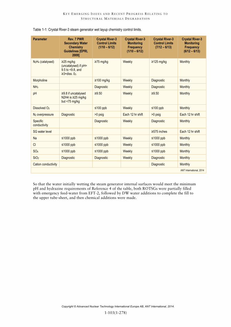
Table 1-1: Crystal River-3 steam generator wet layup chemistry control limits.
Parameter Rev. 7 PWR Secondary Water
Chemistry Guidelines [EPRI,
2009]
Crystal River-3 Control Limits (1/10 – 6/12)
Crystal River-3 Monitoring Frequency
(1/10 – 6/12)
Crystal River-3 Control Limits (7/12 – 6/13)
Crystal River-3 Monitoring Frequency
(6/12 – 6/13)
N2H4 (catalysed) ≥25 mg/kg (uncatalysed) if pH= 9.5 to <9.8, and ≥3×diss. 02.
≥75 mg/kg Weekly ≥125 mg/kg Monthly
Morpholine ≥100 mg/kg Weekly Diagnostic Monthly
NH3 Diagnostic Weekly Diagnostic Monthly
pH ≥9.8 if uncatalysed N2H4 is ≥25 mg/kg but <75 mg/kg
≥9.50 Weekly ≥9.50 Monthly
Dissolved O2 ≤100 ppb Weekly ≤100 ppb Monthly
N2 overpressure Diagnostic >0 psig Each 12 hr shift >0 psig Each 12 hr shift
Specific conductivity
Diagnostic Weekly Diagnostic Monthly
SG water level ≥575 inches Each 12 hr shift
Na ≤1000 ppb ≤1000 ppb Weekly ≤1000 ppb Monthly
Cl ≤1000 ppb ≤1000 ppb Weekly ≤1000 ppb Monthly
SO4 ≤1000 ppb ≤1000 ppb Weekly ≤1000 ppb Monthly
SiO2 Diagnostic Diagnostic Weekly Diagnostic Monthly
Cation conductivity Diagnostic Monthly ANT International, 2014
So that the water initially wetting the steam generator internal surfaces would meet the minimum pH and hydrazine requirements of Reference 4 of the table, both ROTSGs were partially filled with emergency feed-water from EFT-2, followed by DW water additions to complete the fill to the upper tube-sheet, and then chemical additions were made.

K E Y E M E R G I N G I S S U E S A N D R E C E N T P R O G R E S S R E L A T I N G T O
S T R U C T U R A L M A T E R I A L S D E G R A D A T I O N
Copyright © Advanced Nuclear Technology International Europe AB, ANT International, 2014.
1-104(1-278)
Weekly sampling of each ROTSG and chemical analysis of the water samples were performed. Due to an expected outage duration of less than 2 years at this time, and based on the success of the wet layup of the original OTSGs during a previous long-term shutdown, no evaluation of the adequacy of this wet layup chemistry for an extended outage was considered necessary. The ROTSGs were in full wet layup throughout the extended outage, except during the time that the reactor was refuelled (11/10 – 5/11) when they were in partial wet layup (filled to ~8.9 m) so the ROTSGs could provide backup decay heat removal if needed. Fairly rapid losses of catalysed hydrazine and morpholine in the wet layup water were observed during the initial ROTSG filling sequences. While not rigorously investigated at the time of occurrence, much later it was discovered that improper balancing of the DW flow into and out of the recirculation pump seal caused a dilution of the chemical concentrations. This was later corrected. The morpholine and catalysed hydrazine concentrations were raised to 300 mg/kg each and remained above the target concentration for subsequent chemical additions in order to minimize the frequency of additions needed to keep their concentrations above the lower control limits. In June 2012, the sampling and analysis frequency of the wet layup water was reduced from weekly to monthly. The reduction in sampling frequency was based on the decreasing low concentration of impurities to values of <20 µg/kg and the observed rate of change in morpholine and catalysed hydrazine concentrations after 19 months of wet layup. No catalysed hydrazine or morpholine additions have been required since June 2012. Monthly sampling/analysis of the ROTSGs has continued as of the time of this writing (early 2013).
In parallel with an in-depth literature review, the authors have conducted electrochemical potential experiments to specifically examine the electrochemical behaviour of both carbon steel and Alloy-600 tubing material in simulated wet-layup solutions. The data from this program demonstrates that the most important element of a wet layup program for protection of the SG is the active exclusion of air by maintaining a nitrogen overpressure. In the event of air in-leakage during layup, protection of carbon and low alloy steel components can be provided by either utilizing hydrazine or carbohydrazide concentrations in excess of those recommended in the current guidelines or by maintaining a minimum pH of 10.0. In conclusion, the recommended approach to long term wet layup for protection of both carbon steel and tubing material is to:
• use only deaerated demineralized fill water;
• maintain the pH at or above 10.5;
• maintain >100 mg/kg of residual hydrazine; and
• rigorously maintain a nitrogen cover gas at a positive overpressure.
Reference [Fyfitch et al, 2014a] is a review of Alloy 600 and Alloy 182 PWSCC in CRDM nozzles and welds in PWRs, in addition, a discussion of potential future expectations is also provided.
The first instance of CRDM nozzle cracking occurred in France in 1991. Subsequent to this, PWSCC of Alloy 600 base metal and Alloy 82/182 weld materials have been identified in numerous other PWR RV heads worldwide. The following flaw observations can be summarized from worldwide inspection results:
• A large majority of the flaws detected have been axially-oriented.
• The majority of flaws in the U.S. have been identified to initiate on the OD of the nozzle below the partial penetration (i.e., J-groove) weld at the 180° and 0° azimuthal locations, whereas the majority of flaws in France have been identified to initiate on the ID of the nozzle below and radially in front of the J-groove weld at respectively the 180° and 0° azimuthal locations.
• Circumferential flaws that have been observed at or near the top of the J-groove weld have all been located on the nozzle OD, specifically for some leaking nozzles.
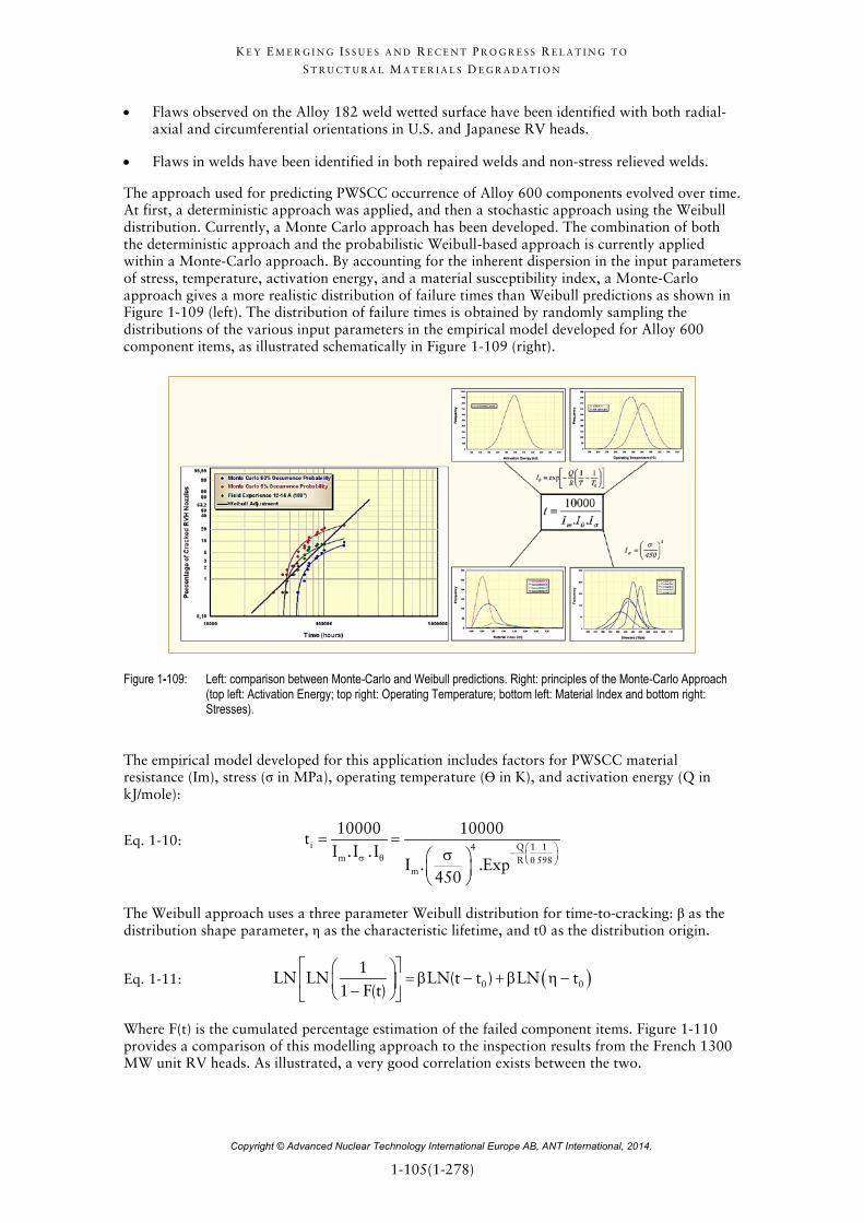
K E Y E M E R G I N G I S S U E S A N D R E C E N T P R O G R E S S R E L A T I N G T O
S T R U C T U R A L M A T E R I A L S D E G R A D A T I O N
Copyright © Advanced Nuclear Technology International Europe AB, ANT International, 2014.
1-105(1-278)
• Flaws observed on the Alloy 182 weld wetted surface have been identified with both radial-axial and circumferential orientations in U.S. and Japanese RV heads.
• Flaws in welds have been identified in both repaired welds and non-stress relieved welds.
The approach used for predicting PWSCC occurrence of Alloy 600 components evolved over time. At first, a deterministic approach was applied, and then a stochastic approach using the Weibull distribution. Currently, a Monte Carlo approach has been developed. The combination of both the deterministic approach and the probabilistic Weibull-based approach is currently applied within a Monte-Carlo approach. By accounting for the inherent dispersion in the input parameters of stress, temperature, activation energy, and a material susceptibility index, a Monte-Carlo approach gives a more realistic distribution of failure times than Weibull predictions as shown in Figure 1-109 (left). The distribution of failure times is obtained by randomly sampling the distributions of the various input parameters in the empirical model developed for Alloy 600 component items, as illustrated schematically in Figure 1-109 (right).
Figure 1-109: Left: comparison between Monte-Carlo and Weibull predictions. Right: principles of the Monte-Carlo Approach (top left: Activation Energy; top right: Operating Temperature; bottom left: Material Index and bottom right: Stresses).
The empirical model developed for this application includes factors for PWSCC material resistance (Im), stress (σ in MPa), operating temperature (ϴ in K), and activation energy (Q in kJ/mole):
Eq. 1-10: i Q 1 14m R 598
m
10000 10000t
I .I . II . .Exp
450
− σ θ θ
= =σ
The Weibull approach uses a three parameter Weibull distribution for time-to-cracking: β as the distribution shape parameter, η as the characteristic lifetime, and t0 as the distribution origin.
Eq. 1-11: ( )0 0
1LN LN LN(t t ) LN t
1 F(t)
= β − + β η − −
Where F(t) is the cumulated percentage estimation of the failed component items. Figure 1-110 provides a comparison of this modelling approach to the inspection results from the French 1300 MW unit RV heads. As illustrated, a very good correlation exists between the two.

K E Y E M E R G I N G I S S U E S A N D R E C E N T P R O G R E S S R E L A T I N G T O
S T R U C T U R A L M A T E R I A L S D E G R A D A T I O N
Copyright © Advanced Nuclear Technology International Europe AB, ANT International, 2014.
1-106(1-278)
Figure 1-110: Comparison of Monte-Carlo simulation of RV head CRDM nozzle cracking to inspection results for French 1300 MW Units.
As Alloy 600 continues to remain in service in U.S. RV heads and inspections continue on a regular basis, additional instances of PWSCC of the CRDM nozzles and welds are anticipated. Cracking observations in both the hot and cold head units should be expected. As in previous years, repairs are available that can be implemented for cracked nozzles. A number of mitigation options are also available for application to CRDM nozzles. And finally, procurement and installation of a new RV head with PWSCC resistant materials has been the option of choice for the majority of utilities.
Reference [Boccanfuso & van der Lee, 2014] present an ambitious project of post-mortem investigations on two retired SGs. Between 2014 and 2021, EDF will be undertaking a major testing and evaluation project called Sherlock, with two retired SGs in order to improve the understanding of ageing mechanisms and to support the asset management of SGs. The two SGs selected are one from Cruas 4, a 900 MWe 3 loop plant, currently scheduled to be replaced in 2014. The other is from Paluel 2, a 1300 MWe 4 loop plant, currently scheduled to be replaced in 2015. These SGs, when retired from service, will be housed horizontally at their respective plant sites.
One of the main objectives of Sherlock is to get a maximum amount of information on a lot of damage mechanisms. This will be achieved, on one hand, through in-situ non-destructive tests, either on the primary or on the secondary side. On the other hand, several large samples will be cut, while taking care to preserve their environment, for destructive examinations in a hot laboratory. All this work will contribute to fully understand the degradation mechanisms on several topics:
• Fatigue: this damage has led to several primary/secondary leaks in France,
• Wear: the principal proven mode of damage of 690 Alloy tubes around the world,
• 690 plugs: these components show the highest level of deformation, hence a high SCC risk, which one can find among all the primary circuit components.
• OD corrosion: first occurrences of this damage have recently been reported worldwide on 600TT Alloy tubes, with several different aggravating factors,

K E Y E M E R G I N G I S S U E S A N D R E C E N T P R O G R E S S R E L A T I N G T O
S T R U C T U R A L M A T E R I A L S D E G R A D A T I O N
Copyright © Advanced Nuclear Technology International Europe AB, ANT International, 2014.
1-261(1-278)
SCWR is one of the Generation IV reactor concepts proposed by the research group of the University of Tokyo in Japan since 1989. The advantages are the compactness of the plant system due to the high specific enthalpy of a supercritical fluid, its high thermal efficiency, and plant simplification. There are numerous challenges for a practical application of the SCWR system, particularly with respect to materials selection and development. Zr alloys, which are mainly used as fuel cladding materials in current LWRs, cannot be applied for SCWR because of severe corrosion problems at high temperatures. Therefore, the development of alternative fuel cladding materials is needed. Ni-based alloys, such as Alloy 690, and high-Cr ASSs such as type 310S SS were proposed because of their high corrosion resistance at high temperature and high pressure water conditions. However, creep strength poverty may occur in these materials if the maximum cladding surface temperature of the SCWR reaches around 700°C, as recent researches suggested. Based on the advanced 15Cr-20Ni ASS developed by the JAEA for sodium cooled fast reactors, a variety of candidate materials for the fuel cladding were manufactured. However, oxidation data of these materials are very limited. Major possible problems caused by oxidation of fuel cladding materials in supercritical water are: a decrease in the heat transfer coefficient, a decrease in the flow rate of the coolant due to a decrease in clearance between fuel rods, and radioactive contamination of the system due to spalling of oxide layers. Therefore, an accurate prediction of the oxide layer growth, based on the oxidation kinetics of the candidate materials, is needed to manage the possible problems mentioned above. In [Abe et al, 2014], the oxidation kinetics of SCWR fuel cladding candidate materials, including three types of 15Cr-20Ni austenitic stainless steels (1520 SSs), in supercritical water at 700°C under 24 MPa has been investigated. The applicability of the candidate materials for the fuel cladding in SCWR from oxidation kinetics and spalling susceptibility of oxide layer points of view has been discussed based on the results of oxidation experiments and prediction of oxide layer growth. Characteristics of oxide layers and its relation to oxidation behaviours are also discussed. Our main findings are summarized as follows:
1) While spalling of oxide layer was observed in the 1520 SSs plate specimens regardless the degree of cold work, the cladding tube-shaped 1520 SSs showed a very low oxidation kinetics and no spalling (Figure 1-312). It has been considered that the tube-shaped 1520 SSs show good performance as fuel cladding in SCWR from oxidation kinetics point of view.

K E Y E M E R G I N G I S S U E S A N D R E C E N T P R O G R E S S R E L A T I N G T O
S T R U C T U R A L M A T E R I A L S D E G R A D A T I O N
Copyright © Advanced Nuclear Technology International Europe AB, ANT International, 2014.
1-262(1-278)
Figure 1-312: Weight gain vs. time of the 1520 SSs in supercritical water at 700°C with 200 ppb DO. (a): 1520S SS, (b): 1520Ti SS, (c):1520Zr SS.
2) The high oxidation resistance of the tube is due to a protective Cr-rich oxide layer formation on the outside surface of the tubes (Figure 1-313).

K E Y E M E R G I N G I S S U E S A N D R E C E N T P R O G R E S S R E L A T I N G T O
S T R U C T U R A L M A T E R I A L S D E G R A D A T I O N
Copyright © Advanced Nuclear Technology International Europe AB, ANT International, 2014.
1-263(1-278)
Figure 1-313: SEM-EDX mapping results of the cross sectional view of the oxide layer at the end of a 1520S SS tube specimen.
It has been considered that Cr diffusion in the outside surface of the tubes was accelerated as a result of an increase of dislocation density and/or grain refinement by a high degree of CW.

K E Y E M E R G I N G I S S U E S A N D R E C E N T P R O G R E S S R E L A T I N G T O
S T R U C T U R A L M A T E R I A L S D E G R A D A T I O N
Copyright © Advanced Nuclear Technology International Europe AB, ANT International, 2014.
1-264(1-278)
1.15 Miscellaneous, general paper Only one paper in this category which relates to Proactive Materials Degradation Management (PMDM) and to long term operation [Shoji et al, 2014]. Predictive and preventive maintenance technologies are increasingly of importance for the long term operation of LWR plants world-widely. In order for the long term operation to be successful with maintaining safety, integrity and reliability, it is essential that aging degradation phenomena should be proactively recognized and properly managed by using adequate R & D and maintenance programs based on the improved predictive capability of the aging phenomena and evaluating their rates of degradation. [Shoji et al, 2014] presented some of the results from the outcome from the Japan Nuclear Regulatory Agency Program based upon the activities by the PMDM Experts' Panel meeting for the last 6 years. Prioritization of the topics that are proposed and scored by the Experts are based on the three important evaluation factors as commonly used in Phenomenon Identification and Ranking Table, PIRT (Figure 1-314); those three are susceptibility level, knowledge level and confidence level, where the aging degradation phenomenon in LWR structural materials has been proactively evaluated and discussed and significant elicitation was made by the Experts (Figure 1-315). Some important topics related environment-induced degradation are introduced and discussed in the paper.
Figure 1-314: PIRT approach and categorization for proactive degradation evaluation. The issues raised as latent/cascade materials degradation phenomena and possible latent degradation issues scoring result on as shown in red dotted circle.

K E Y E M E R G I N G I S S U E S A N D R E C E N T P R O G R E S S R E L A T I N G T O
S T R U C T U R A L M A T E R I A L S D E G R A D A T I O N
Copyright © Advanced Nuclear Technology International Europe AB, ANT International, 2014.
1-265(1-278)
Figure 1-315: Two typical issues raised as a possible degradation phenomena with good consensus and large scatter in evaluation and their confidence levels in the judgment of susceptibility.
1.16 Recent (2013-2014) related literature review
1.16.1 Stainless Steels corrosion
316L SS has been widely used for the RPV cladding and piping systems in the PWRs. In recent years, accidents of SCC in 316L SS pipes were reported in PWRs. Strain-hardening may play an important role in the occurrence of inter-granular SCC. Laboratory data show that strain-hardening from cold work could significantly enhance the crack growth of austenitic stainless steels in simulated PWR primary water environment. SCC commonly leads to a failure of the nuclear power plants due to leakage, if burnable gases like hydrogen are released, fires and even explosions cannot be excluded. High concentration of O2 can accumulate in the local occluded volumes, which will make the 316L SS pipe susceptible to SCC failures. The effect of DO is particularly significant in the SCC behaviour of 316L SS in PWR primary water, since it may affect the film formed on the crack tip, electrochemical parameters and electrochemical process, ion species and pH near the crack tip, etc. The purpose of the reference [Zhang & Wang, 2014] is to investigate the effect of DO content on the SCC behaviour of a CW nuclear grade 316L SS in simulated PWR primary water containing oxygen but no hydrogen, and provide CGR data. The following conclusions can be made:
1) The SCC crack growth rates increase with increasing DO content in the simulated PWR primary water environment (Figure 1-316).

K E Y E M E R G I N G I S S U E S A N D R E C E N T P R O G R E S S R E L A T I N G T O
S T R U C T U R A L M A T E R I A L S D E G R A D A T I O N
Copyright © Advanced Nuclear Technology International Europe AB, ANT International, 2014.
1-266(1-278)
Figure 1-316: The effect of DO content on the CGR of the CW nuclear grade 316L SS in simulated PWR primary water.
2) Typical IGSCC propagated along random grain boundaries (Figure 1-317) and high residual strain was observed in the region near the crack.
Figure 1-317: EBSD results (step size = 6 µm) of the cracking path area on the side surface of the CW nuclear grade 316L SS. Top: image, bottom: IPF.

K E Y E M E R G I N G I S S U E S A N D R E C E N T P R O G R E S S R E L A T I N G T O
S T R U C T U R A L M A T E R I A L S D E G R A D A T I O N
Copyright © Advanced Nuclear Technology International Europe AB, ANT International, 2014.
1-267(1-278)
1.16.2 Nickel alloys
[Hwang, 2013] contains a good summary of the history of the worldwide A600 PWSCC, except SG tubes and of some mitigation techniques. The major interest of this paper is the reporting of some Korean PWSCC failures not yet in the open literature. We will stress here on these particular field events.
2007: leak of a SG drain nozzle (cold leg) at YG-3 after 13 years of operation (around 11 EFPYs). This was the first PWSCC failure in Korea (except SG tubes). Unlike Alloy 600 nozzle at the cold leg side, Alloy 690 material was equipped with SG bottom head at the hot leg drain nozzle from the beginning of operation as seen in Figure 1-318.
Figure 1-318: Different nozzle material due to welding specification limitation during construction in a steam generator in Korea.
While implementing the inspection and evaluation program of the BAC which was a part of the 10th annual overhaul, an indication of boric acid leakage was identified at the SG ‘02B’ bowl drain nozzle of the cold-leg side. The BAC program was first initiated for the Yonggwang Unit-3 at the 8th annual overhaul in 2004 based on the operational experience of the Davis Besse plant. Upon investigation, few linear defects were identified at the inside of that drain nozzle and the defect was assumed to be due to PWSCC. And the indication of boric acid leakage was identified as an infinitesimal leakage of the primary coolant thru the crack. This event was attributed to the structural deterioration caused by the possible PWSCC. The inspection team confirmed the integrity of the penetration hole used to install the drain nozzle and the integrity of the SG base metal.
The plant implemented the following corrective actions:
• Removed the indication of the boric acid;
• Removed the existing drain nozzle and inserted a temporal plug which was manufactured and designed according to the ASME Code Sec. III;
• Confirmed that the temporal plug can secure next one cycle operation;
• Installed a CCTV to monitor leakage;
• Plan to implement a permanent maintenance during next overhaul;
• Plan to maintain the same nozzle of the SG ‘01B’ during next overhaul.

K E Y E M E R G I N G I S S U E S A N D R E C E N T P R O G R E S S R E L A T I N G T O
S T R U C T U R A L M A T E R I A L S D E G R A D A T I O N
Copyright © Advanced Nuclear Technology International Europe AB, ANT International, 2014.
1-268(1-278)
2008: leak of another SG drain nozzle (cold leg) at YG-4 after also 13 years of operation (around 11 EFPYs again) (Figure 1-319). In both cases (2007 and 2008 events), the defects were typical PWSCC in terms of their inter-granular morphology and initiation site as shown in Figure 1-320.
Figure 1-319: Location and indication of boric acid leakage.
Figure 1-320: Bowl drain nozzle and indication of PWSCC.
GB carbides existed in the material, and therefore the material itself was not considered to be the main attributor of the cracking. Instead, residual stress due to the welding process or machining process on the inner surface was considered to be the main cause of the PWSCC of the Alloy 600 nozzle. Basically, the plant implemented the same corrective actions than for unit 3 (Figure 1-321).

K E Y E M E R G I N G I S S U E S A N D R E C E N T P R O G R E S S R E L A T I N G T O
S T R U C T U R A L M A T E R I A L S D E G R A D A T I O N
Copyright © Advanced Nuclear Technology International Europe AB, ANT International, 2014.
1-269(1-278)
Figure 1-321: Cross-sectional view of bowl drain nozzle before and after plugging.
2010: PWSCC of the RPV upper head vent pipe at YG-3 after 16 years of operation. While implementing the visual inspection on the RV penetration lines during its 12th annual overhaul on February 25, 2010, indication of boric acid leakage was identified at the RPVH vent nozzle (Figure 1-322).
Figure 1-322: RPVH of YG-3, location of boric acid leakage.
Upon investigation, two small axial cracks were identified at the vent nozzle where contacted with the vessel head and the cracks were appeared to be due to PWSCC (Figure 1-323).