kepserverex v5 help - omron · kepserverex v5help tableofcontents tableofcontents 2 introduction 9...
TRANSCRIPT

KEPServerEX V5 Help
© 2015 Kepware, Inc.

KEPServerEX V5 Help
Table of ContentsTable of Contents 2
Introduction 9
System Requirements 10
Server Summary Information 10
Components 11
Process Modes 12
Interfaces and Connectivity 13
OPCDA 13
OPC AE 13
OPC UA 15
OPC .NET 15
DDE 16
FastDDE/SuiteLink 16
iFIX Native Interfaces 16
Thin-Client Terminal Server 17
Accessing the Administration Menu 18
Settings 19
Settings - Administration 20
Settings - Configuration 21
Settings - Runtime Process 22
Settings - Runtime Options 23
Settings - Event Log 24
Settings - ProgID Redirect 26
Settings - User Manager 28
Navigating the Configuration 32
Project Properties 35
Project Properties - Identification 35
Project Properties - OPC DA Settings 35
Project Properties - DDE 38
Project Properties - FastDDE/Suitelink 40
Project Properties - iFIX PDB Settings 41
Project Properties - OPC UA 42
Project Properties - OPC AE 44
Project Properties - OPC HDA 46
Project Properties - OPC .NET 47
Server Options 48
Options - General 48
Options - Runtime Connection 49
Basic Server Components 50
What is a Channel? 50
www. kepware.com
2

KEPServerEX V5 Help
Channel Properties - General 50
Channel Properties - Communications 52
Additional Ethernet Encapsulation Settings 57
Channel Properties - Communication Serialization 59
Channel Properties - Network Interface 60
Channel Properties - Write Optimizations 61
Channel Properties - Device Discovery 63
Channel Properties - Advanced 64
What is a Device? 65
Device Properties - General 65
Device Properties - Scan Mode 68
Device Properties - Ethernet Encapsulation 69
Device Properties - Timing 70
Device Properties - Auto-Demotion 72
Device Properties - Time Synchronization 73
What is a Tag? 75
Tag Properties - General 75
Multiple Tag Generation 78
Tag Properties - Scaling 81
Dynamic Tags 82
Static Tags (User-Defined) 84
What is a Tag Group? 84
Tag Group Properties 84
What is the Alias Map? 85
Alias Properties 86
What is the Event Log? 87
Event Log Display 87
Event Log Page Setup 89
Tag Management 90
CSV Import and Export 90
Automatic OPC Tag Database Generation 92
System Tags 96
Property Tags 106
Statistics Tags 107
Modem Tags 109
Communication Serialization Tags 111
Communications Management 113
Using a Modem in the Server Project 113
Phonebook Tags 115
Phone Number Tags 116
Modem Auto-Dial 117
Built-In Diagnostics 119
OPCDiagnostics Viewer 119
www. kepware.com
3
KEPServerEX V5 Help
OPCDiagnostic Events 122
Communication Diagnostics 128
iFIX Signal Conditioning Options 131
Project Startup for iFIX Applications 136
Designing a Project 137
Running the Server 137
Starting a New Project 137
Adding and Configuring a Channel 138
Adding and Configuring a Device 139
Adding User-Defined Tags 141
Browsing for Tags 144
GeneratingMultiple Tags 145
Adding Tag Scaling 149
Saving the Project 150
Testing the Project 151
New Channel - Identification 157
New Channel - Device Driver 157
New Channel - Communications 158
New Channel - Modem Auto Dial 159
New Channel - Connection Behavior 160
New Channel - Summary 161
New Device - Name 162
New Device - Model 163
New Device - ID 163
New Device - Scan Mode 165
New Device - Timing 165
New Device - Summary 166
How Do I... 167
How To... Allow Desktop Interactions 167
How To... Create and Use an Alias 168
How To... Optimize the Server Project 170
How To... Properly Name a Channel, Device, Tag, and Tag Group 171
How To... Resolve Comm IssuesWhen the DNS/DHCP Device Connected to the Server isPower Cycled 171
How To... Use an Alias to Optimize a Project 173
How To... Use DDE with the Server 174
How To... Use Dynamic Tag Addressing 175
How To... Use Ethernet Encapsulation 175
How To... Use Net DDE Across a Network 177
How To ... Work with Non-Normalized Floating Point Values 177
Device Demand Poll 179
Message Descriptions 180
General Operation System Messages 180
www. kepware.com
4

KEPServerEX V5 Help
Dialing <phone number> on line <modem name>. 180
Dialing aborted on <modem name>. 180
Dialing on line <modem name> canceled by user. 181
Failed to open modem line <modem name> [TAPI error]. 181
Hardware error on line <modem name>. 181
Incoming call detected on line <modem name>. 181
Line <modem name> connected. 182
Line <modem name> connected at <baud rate> baud. 182
Line <modem name> disconnected. 182
Line <modem name> is already in use. 182
Line dropped at remote site on <modem name>. 182
Modem line closed: <modem name>. 183
Modem line opened: <modem name>. 183
Modem to Modem DCE: <connection parameters>. 183
MODEMSETTINGS unavailable. 184
No comm handle provided on connect for line <modem name>. 184
No dial tone on <modem name>. 184
Remote line is busy on <modem name>. 184
Remote line is not answering on <modem name>. 185
Socket error <code> occurred on <device name>. Operation <operation name> failed because<reason>. 185
TAPI configuration has changed, reinitializing... 185
TAPI line initialization failed: <modem name>. 185
The phone number is invalid <phone number>. 186
Unable to apply Modem Configuration on line <modem name>. 186
Unable to dial on line <modem name>. 186
Unable to start Net DDE. 186
iFIX Messages 187
Attempt to add iFIX PDB item < item name> failed. 187
Failed to enable iFIX PDB support for this server [OS error = n]. 187
Unable to enable iFIX PDB support for this server. 187
Unable to read <tag name> on device <channel name/device name>. 188
Server Administration Messages 188
Cannot export user information until all passwords have been updated. 188
Password for user <name> has been changed. 188
Password for user 'Administrator' was reset by <Windows user>. 189
Password reset for user 'Administrator' failed. <Windows user> is not a Windows administrator. 189
Permissions definition has changed on user group <name>. 189
User <name> has been created as a member of user group <name>. 189
User <name> has been disabled. 190
User <name> has been enabled. 190
User <name> has been renamed to <new name>. 190
User <name> moved from user group <old group> to <new group>. 190
User group <name> has been created. 190
User group <name> has been disabled. 191
www. kepware.com
5

KEPServerEX V5 Help
User group <name> has been enabled. 191
User group <name> has been renamed to <new name>. 191
User information replaced by import from <file name>. 191
Server Configuration Messages 192
<device name> device driver loaded successfully. 192
<driver name> device driver unloaded frommemory. 192
<driver name> device driver was not found or could not be loaded. 193
<Driver name> driver does not currently support XML persistence. 193
<Plug-in> plug-in was not found or could not be loaded. 193
<COM/Modem ID> is already in use by channel <channel name>. 194
<COM/Modem ID> is already in use on <virtual network>. 194
<Virtual network> already contains a shared connection. 194
A client application has <enabled/disabled> auto-demotion on device <device name>. 194
A connection share pairing on <COM/Modem ID> is not supported by drivers <driver name> and<driver name>. 195
Closing project <project name>. 195
Created backup of project <project name> to <file location>. 195
Error importing CSV tag record <record number>: <tag name> is not a valid tag group name. 195
Error importing CSV tag record <record number>: <tag name> is not a valid tag name. 196
Error importing CSV tag record <record number>: Missing address. 196
Error importing CSV tag record <record number>: Tag or group name exceeds 256 characters. 196
Failed to reset channel diagnostics. 196
Failed to retrieve Runtime project. 197
Invalid Ethernet encapsulation IP <IP address>. 197
Invalid or missing modem configuration on channel <channel name>, substituting <modem>. 197
Invalid XML document <XML name>. 197
Maximum channel count exceeded for the lite version <driver name> driver license. 198
Maximum device count exceeded for the lite version <driver name> driver license. 198
Maximum Runtime tag count exceeded for the lite version <driver name> driver license. 198
Modem initialization failed on channel <channel name>. 199
Opening project <project name>. 199
Project containing custom access control permissions cannot be saved as XML. 199
Required schema file <schema name> not found. 199
Runtime project update failed. 200
Starting OPC diagnostics. 200
Stopping OPC diagnostics. 200
Unable to add channel due to driver-level failure. 200
Unable to add device due to driver-level failure. 201
Unable to backup project file to <file path>. 201
Unable to begin device discovery on channel <channel name>. 201
Unable to launch OPC Quick Client [Path: <path> OS error: <error>]. 202
Unable to load driver DLL <driver name>. 202
Unable to load the <driver name> driver because more than one copy exists (<driver name> and<driver name>). 202
Unable to use network adapter <adapter> on channel <channel name>. Using default networkadapter. 202
www. kepware.com
6

KEPServerEX V5 Help
Validation error on <tag name>: Invalid scaling parameters. 203
Server Runtime Messages 203
<Driver name> device driver was not found or could not be loaded. 204
<Server name> server started. 204
<Server Runtime> successfully configured to run as a system service. 204
<Server runtime> successfully removed from the service control manager database. 205
Access denied to user <name> requesting <permission> on <object path>. 205
Attempt to add DDE item <item name> failed. 205
Attempt to add FastDDE/SuiteLink item <tag name> failed. 205
Attempt to add OPC client item <item name> failed. 206
Attempting to automatically generate tags for device <device name>. 206
Auto generation for tag <tag name> already exists and will not be overwritten. 206
Auto generation produced too many overwrites, stopped posting error messages. 207
Cannot delete <object path> because it belongs to a client access policy defined under user group<user group name>. 207
Channel diagnostics started on channel <channel name>. 207
Channel diagnostics stopped on channel <channel name>. 207
Completed automatic tag generation for device <device name>. 208
Configuration session assigned to <user name> as default user has ended. 208
Configuration session assigned to <user name> demoted to read only. 208
Configuration session assigned to <user name> promoted to write access. 208
Configuration session started by <user name>. 208
Configuration TCP/IP port number changed to <port number>. 209
Data collection is <enabled/disabled> on device <device name>. 209
DDE client attempt to add topic <topic> failed. 209
Delete object <item name> failed. 209
Demo timer started. <Days> <hours> <minutes> <seconds>. 210
Demo timer updated. <time remaining>. 210
Demonstration time period has expired for <feature name>. 210
Device <device name> has been auto-demoted. 211
Device <device name> has been auto-promoted to determine if communications can be re-established. 211
Failed to upload project XML. 211
FLEXnet Licensing Service must be enabled to process your license. Runtime references are limitedto demo operation. 212
Module <module> is unsigned or has a corrupt signature. Runtime references are limited to demooperation. 212
Move object <group> to <group> failed. 212
Move object <object> failed. 212
No device driver DLLs were loaded. 213
Runtime project replaced from <project location>. 213
Simulation mode is disabled on device <device name>. 213
Simulation mode is enabled on device <device name>. 213
Starting <driver name> device driver. 214
Starting <plug-in name> plug-in. 214
Stopping <driver name> device driver. 214
www. kepware.com
7

KEPServerEX V5 Help
Stopping <plug-in name> plug-in. 214
The tier information for feature <feature> is invalid. 214
Unable to generate a tag database for device <device name>. Reason: <reason> 215
Unable to generate a tag database for device <device name>. The device is not responding. 215
Unable to load project <project name>. 215
Unable to write to item <item name>. 215
Update of object <object> failed. 216
Write request rejected on item reference <item name> since the device it belongs to is disabled. 216
Write request rejected on read-only item reference <item name>. 216
Index 218
www. kepware.com
8

KEPServerEX V5 Help
CONTENTS
IntroductionInterfaces and ConnectivityAccessing the Administration MenuNavigating the ConfigurationBasic Server ComponentsTag ManagementCommunications ManagementBuilt-In DiagnosticsDesigning a ProjectHow Do I... ?Error Descriptions
Note: For information regarding product licensing, refer to the License Utility help file. To access the help filethrough the server Configuration menu, click Help | Server Help | License Utility. To access the help file throughthe server Administration menu, right-click on the KEPServerEX icon in the System Tray and then select Help |License Utility.
Help version 1.378
IntroductionThis software based server is designed for accurate communications, quick setup and unmatchedinteroperability between client applications, industrial devices and systems. The server provides a wide range ofplug-in device drivers and components that suit most communication needs. The plug-in design and single userinterface provides consistent access from standards-based applications (such as OPC) and non-standards basedapplications with native interfaces.
www. kepware.com
9
KEPServerEX V5 Help
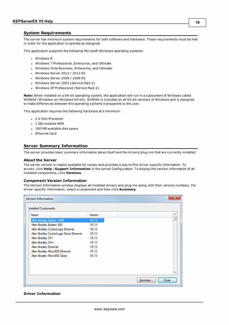
System RequirementsThe server has minimum system requirements for both software and hardware. These requirements must be metin order for the application to operate as designed.
This application supports the following Microsoft Windows operating systems:
l Windows 8l Windows 7 Professional, Enterprise, and Ultimatel Windows Vista Business, Enterprise, and Ultimatel Windows Server 2012 / 2012 R2l Windows Server 2008 / 2008 R2l Windows Server 2003 (Service Pack 2)l Windows XP Professional (Service Pack 2)
Note:When installed on a 64-bit operating system, the application will run in a subsystem of Windows calledWOW64 (Windows-on-Windows 64 bit). WOW64 is included on all 64-bit versions of Windows and is designedto make differences between the operating systems transparent to the user.
This application requires the following hardware at a minimum:
l 2.0 GHz Processorl 1 GB installed RAMl 180 MB available disk spacel Ethernet Card
Server Summary InformationThe server provides basic summary information about itself and the drivers/plug-ins that are currently installed.
About the ServerThe server version is readily available for review and provides a way to find driver-specific information. Toaccess, click Help | Support Information in the server Configuration. To display the version information of allinstalled components, click Versions.
Component Version InformationThe Version Information window displays all installed drivers and plug-ins along with their version numbers. Fordriver-specific information, select a component and then click Summary.
Driver Information
www. kepware.com
10

KEPServerEX V5 Help
The Driver Information window provides a summary of the driver's default settings. For example, each driverdisplays its maximum number of supported channels.
Descriptions of the information available is as follows:
l Summary provides the driver name and type, the maximum number of supported channels, and thenumber of models in the driver.
l COMM Defaults displays the driver's default settings, which may or may not match the settings of thedevice being configured.
l Driver flag definitions displays the driver library functions and indicates whether they have beenenabled in the driver.
l Model Information displays device-specific addressing and features. It lists the name for eachsupported model in addition to its addressing values and other features.
ComponentsThe server implements client/server architecture. The components include Configuration, Runtime,Administration, and Event Log.
ConfigurationThe Configuration is the client-user interface that is used to modify the Runtime's project. The Configuration canbe launched by multiple users and support remote Runtime configuration.
CSV Import and ExportThis server supports the import and export of tag data in a Comma Separated Variable (CSV) file. When usingCSV import and export, tags are created quickly in the desired application. For more information, refer toCSV Import and Export.
RuntimeThe Runtime is the server component that starts as a service by default. Clients can connect to the runtimeremotely or locally.
AdministrationThe Administration is used to view and/or modify settings and launch applications that pertain to usermanagement and the server. By default, the Administration is started and sent to the System Tray when a useraccount logs onto the operating system.
Event LogThe Event Log service collects information, warning, error, and security events. These events are then sent to theConfiguration's Event Log window for viewing. For more information, refer toWhat is the Event Log?
www. kepware.com
11

KEPServerEX V5 Help
Process ModesThe Runtime's process mode can be changed while the server is running; however, doing so while a client isconnected interrupts the connection for a short period. The modes of operation are System Service andInteractive.
System ServiceBy default, the server is installed and runs as a service. When System Service is selected, the Runtime does notrequire user intervention and starts when the operating system opens. This provides user independent access tothe server by the clients.
InteractiveWhen Interactive is selected, the Runtime remains stopped until a client attempts to connect to it. Once started, itruns until all clients have disconnected and then shuts down. The Runtime also shuts down if the user accountlogs off the operation system.
Note: The Runtime's process mode may be changed to meet client applications' needs through theAdministration settings dialogs.
System Service is required for the following conditions:
l When iFIX is required to run on an operating system while UAC is enabled.
Interactive is required for the following conditions:
l When a communication interface (such as DDE) must exchange information with the user desktop andthe server is installed on Windows Vista, Windows Server 2008, or later operating systems.
See Also:Settings - Runtime ProcessHow To...Allow Desktop Interactions.
www. kepware.com
12
KEPServerEX V5 Help
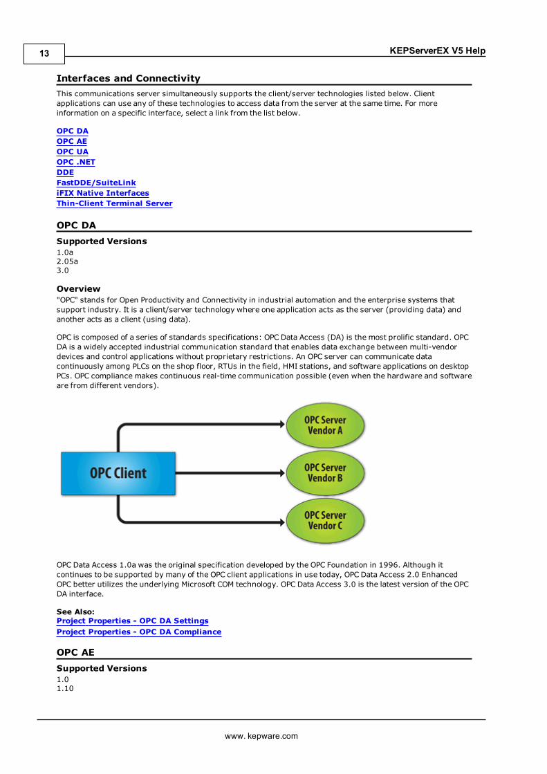
Interfaces and ConnectivityThis communications server simultaneously supports the client/server technologies listed below. Clientapplications can use any of these technologies to access data from the server at the same time. For moreinformation on a specific interface, select a link from the list below.
OPC DAOPC AEOPC UAOPC .NETDDEFastDDE/SuiteLinkiFIX Native InterfacesThin-Client Terminal Server
OPC DASupported Versions1.0a2.05a3.0
Overview"OPC" stands for Open Productivity and Connectivity in industrial automation and the enterprise systems thatsupport industry. It is a client/server technology where one application acts as the server (providing data) andanother acts as a client (using data).
OPC is composed of a series of standards specifications: OPC Data Access (DA) is the most prolific standard. OPCDA is a widely accepted industrial communication standard that enables data exchange between multi-vendordevices and control applications without proprietary restrictions. An OPC server can communicate datacontinuously among PLCs on the shop floor, RTUs in the field, HMI stations, and software applications on desktopPCs. OPC compliance makes continuous real-time communication possible (even when the hardware and softwareare from different vendors).
OPC Data Access 1.0a was the original specification developed by the OPC Foundation in 1996. Although itcontinues to be supported by many of the OPC client applications in use today, OPC Data Access 2.0 EnhancedOPC better utilizes the underlying Microsoft COM technology. OPC Data Access 3.0 is the latest version of the OPCDA interface.
See Also:Project Properties - OPC DA SettingsProject Properties - OPC DA Compliance
OPC AESupported Versions1.01.10
www. kepware.com
13

KEPServerEX V5 Help
OverviewOPC Alarms & Events (AE) is a specification developed by the OPC Foundation to standardize the way that alarmand event information is shared among systems. Using the standard, AE clients can receive alarms and eventnotices for equipment safety limits, system errors, and other abnormal situations.
Simple EventsSimple Events include the server events displayed in the Event Log (such as information, warning, error, andsecurity events). The server supports the following filtering options for Simple Events for AE clients:
l Event Type: Simple.l Event Category: Filter by server-defined categories. Each event is assigned to one category.Descriptions of the categories are as follows:
l Runtime Error Events: Simple events that are shown as errors in the Event Log.l Runtime Warning Events: Simple events that are shown as warnings in the Event Log.l Runtime Information Events: Simple events that are shown as informational in the EventLog.
Condition EventsCondition Events are created by server conditions, which are currently only configurable through the use of theAlarms & Events Plug-In. The server supports the following filtering options for Condition Events for AE clients:
1. Event: Condition.
2. Category: Filter by server-defined categories. Each event is assigned to one category. Descriptions of thecategories are as follows:
l Level Alarms: Events that are generated by process level conditions. For example, tank level >10.
l Deviation Alarms: Events that are generated by deviation conditions. For example, tank level ±10.
l Rate of Change Alarms: Events that are generated by rate of change conditions.
3. Severity: Filter by severity level. Levels range from 0 to 1000; 1000 is the most severe. Each event isassigned a severity.
4. Area: Filter by a process area to get alarms and events from only that area. An area is used to organizealarm and event information.
5. Source: Filter by source to get events from only that source. A source is an Alarms & Events area that wascreated by a source (such as a server tag) that belongs to an area.
Note: The Alarms & Events Plug-In allows conditions to be configured through server tags. For example, aTemperature tag can be configured through the Alarms & Events Plug-In to generate an event when themaximum value is reached. For more information on the Alarms & Events Plug-In, contact an OPC vendor.
See Also:Project Properties - OPC AE
Optional InterfacesThe AE server interface does not support the following optional interfaces:
l IOPCEventServer::QueryEventAttributes: This interface manages event attributes, which are notsupported by the server. Attributes allow custom information to be added to an event (such as specialmessages or server tag values). This also applies to theIOPCEventSubscriptionMgt::SelectReturnedAttributes interface and theIOPCEventSubscriptionMgt::GetReturnedAttributes interface.
l IOPCEventServer::TranslateToItemIDs: This interface allows AE clients to get the OPC DA itemrelated to the event. This is because in some cases, events are related to the value of a server tag.
l IOPCEventServer2: This interface allows clients to enable/disable areas and sources. This interface isnot supported by the server, because it would allow one client to enable/disable an area or source for allclients.
Note: The AE server interface does not support tracking events.
www. kepware.com
14

KEPServerEX V5 Help
OPC UASupported Version1.01 optimized binary TCP
OverviewOPC Unified Architecture (UA) is an open standard created by the OPC Foundation with help from dozens ofmember organizations. It provides an additional way to share factory floor data to business systems (from shop-floor to top-floor). UA also offers a secure method for remote client-to-server connectivity without depending onMicrosoft DCOM. It has the ability to connect securely through firewalls and over VPN connections. Thisimplementation of the UA server supports optimized binary TCP and the DA data model.
Note: Currently, neither UA via HTTP/SOAP web services nor for complex data is supported. For moreinformation, refer to the OPC UA Configuration Manager help file.
OPC UA ProfilesOPC UA is a multi-part specification that defines a number of services and information models referred to asfeatures. Features are grouped into profiles, which are then used to describe the functionality supported by a UAserver or client. For a full list and a description of each OPC UA profile, refer tohttp://www.opcfoundation.org/profilereporting/index.htm.
Fully Supported OPC UA Profiles
l Standard UA Server Profilel Core Server Facetl Data Access Server Facetl SecurityPolicy - Basic128Rsa15l SecurityPolicy - Basic256l SecurityPolicy - Nonel UA-TCP UA-SC UA Binary
Partially Supported OPC UA Profiles
l Base Server Behavior Facet
Note: This profile does not support the Security Administrator – XML Schema.
See Also:Project Properties - OPC UA
OPC .NETSupported Version1.20.2
OverviewOPC .NET is a family of APIs provided by the OPC Foundation that leverage Microsoft's .NET technology and allow.NET clients to connect to the server. This server supports OPC .NET 3.0 WCF, formally known as OPC Xi. Unlikeother OPC .NET APIs, OPC .NET 3.0 uses Windows Communication Foundation (WCF) for connectivity, avoidingDCOM issues and providing the following benefits:
l Secure communication via multiple communications bindings (such as Named Pipe, TCP, Basic HTTP, andWs HTTP).
l Consolidation of OPC Classic Interfaces.l Simple development, configuration, and deployment of Windows environment.
The server adds OPC .NET 3.0 support using a customized version of the OPC .NET 3.0 WCF Wrapper supplied bythe OPC Foundation. The wrapper runs as a system service called "xi_server_runtime.exe". It wraps the existingserver's OPC AE and DA interfaces, providing WCF clients access to the server's tag and alarm data. It does notsupport Historical Data Access (HDA).
Note: The OPC .NET service is only started when the server starts and the interface is enabled. Unlike OPC DA,clients cannot launch the server. For more information on configuration, refer to Project Properties – OPC.NET.
www. kepware.com
15

KEPServerEX V5 Help
RequirementsTo install and use OPC .NET 3.0, Microsoft .NET 3.5 must be present on the machine before server installation.
DDESupported FormatsCF_TextXL_TableAdvanced DDENetwork DDE
OverviewAlthough this server is first and foremost an OPC server, there are still a number of applications that requireDynamic Data Exchange (DDE) to share data. As such, the server provides access to DDE applications thatsupport one of the following DDE formats: CF_Text, XL_Table, and Advanced DDE. CF_Text and XL_Table arestandard DDE formats developed by Microsoft for use with all DDE aware applications. Advanced DDE is a highperformance format supported by a number of client applications specific to the industrial market.
CF_Text and XL_TableThe DDE format CF_Text is the standard DDE format as defined by Microsoft. All DDE aware applications supportthe CF_Text format. XL_Table is the standard DDE format as defined by Microsoft that is used by Excel. For moreinformation on DDE, refer toHow To... Use DDE with the Server.
Advanced DDEAdvanced DDE is the DDE format defined by Rockwell Automation. Today, all Rockwell client applications areAdvanced DDE aware. Advanced DDE is a variation on the normal CF_Text format, which allows larger amounts ofdata to transfer between applications at higher rates of speed (and with better error handling).
Network DDENetwork DDE (Net DDE) is the standard for remote DDE connection as defined by Microsoft. It uses the CF_Textformat. For more information on Net DDE, refer toHow to... Use Net DDE Across a Network.
RequirementsFor the DDE interface to connect with the server, the Runtime must be allowed to interact with the desktop. Formore information, refer toHow To... Allow Desktop Interactions.
See Also:Project Properties - DDE
FastDDE/SuiteLinkOverviewFastDDE is a DDE format defined by Wonderware Corporation. It allows larger amounts of data to transferbetween applications at higher speed (and with better error handling) than generic DDE. SuiteLink is aclient/server communication method that has succeeded FastDDE. It is TCP/IP based and has improvedbandwidth and speed. Both FastDDE and SuiteLink are supported by all Wonderware client applications.
Note: The Wonderware connectivity toolkit is used to simultaneously provide OPC and FastDDE/SuiteLinkconnectivity while allowing for quick access to device data without the use of intermediary bridging software.
Caution: For security reasons, it is recommended that users utilize the most recent Wonderware DAServerRuntime Components. For more information and available downloads, refer to the Invensys Global TechnicalSupport WDN website.
RequirementsFor the FastDDE interface to connect with the server, the Runtime must be allowed to interact with the desktop.For more information, refer toHow To... Allow Desktop Interactions.
See Also:Project Properties - FastDDE/SuiteLink
iFIX Native InterfacesOverviewThe iFIX native interface simplifies the connection task by allowing a direct connection to the local iFIX applicationwithout the use of the iFIX OPC Power Tool. When supported, this interface also has the ability to refine theconnection between the server and the iFIX Process Database (PDB).
www. kepware.com
16

KEPServerEX V5 Help
See Also:Project Properties - iFIX PDB Settings
Thin-Client Terminal ServerOverviewWindows Remote Desktop, which was formerly called Terminal Services, is a Microsoft Windows component thatallows users to access data and applications on a remote computer over a network. It also enablescommunications servers to be configured via remote client machines.
www. kepware.com
17

KEPServerEX V5 Help
Accessing the Administration MenuThe Administration Menu is a tool that is used to view and/or modify user management settings and launchserver applications. To access the Administration Menu, right-click on the Administration icon located in theSystem Tray. The menu should appear as shown below.
Description of the options are as follows:
l Configuration: This option launches the OPC server's configuration.l Start Runtime Service: This option starts the server Runtime process and loads the default Runtimeproject.
l Stop Runtime Service: This option disconnects all clients and then saves the default Runtime projectbefore stopping the server Runtime process.
l Reinitialize: This option disconnects all clients and resets the Runtime server. It automatically saves andreloads the default Runtime project without stopping the server Runtime process.
l Reset Event Log: This option resets the Event Log. The date, time, and source of the reset are added tothe Event Log in the configuration window.
l Settings...: This option launches the Settings dialog. For more information, refer to Settings.l OPC UA Configuration: This option launches the OPC UA Configuration Manager.l OPC .NET Configuration: This option launches the OPC .NET Configuration Manager.l Quick Client: This option launches the Quick Client.l License Utility: This option launches the server's license utility.l Help: This option launches the server's help documentation.l Support Information: This option launches a dialog that contains basic summary information on boththe server and the drivers currently installed for its use. For more information, refer to Server SummaryInformation.
l Exit: This option closes the Administration and removes it from the System Tray. To view it again, select itfrom the Windows Start menu.
www. kepware.com
18

KEPServerEX V5 Help
SettingsTo access the Settings tabs, right-click on the Administration icon located in the System Tray. Then, selectSettings. For more information, select a link from the list below.
Settings - AdministrationSettings - ConfigurationSettings - Runtime ProcessSettings - Runtime OptionsSettings - Event LogSettings - ProgID RedirectSettings - User Manager
www. kepware.com
19

KEPServerEX V5 Help
Settings - AdministrationThe Administration tab is used to configure the Runtime Administration's actions.
Description of the parameter is as follows:
l Automatically start Administration:When checked, this parameter enables the Administration tostart automatically. The Administration is a System Tray application that allows quick links to variousserver tools including the Settings Console, Configuration, Licensing Utility, User Manager Console andcontrols for stopping and starting the Runtime service.
www. kepware.com
20

KEPServerEX V5 Help
Settings - ConfigurationThe Configuration tab is used to configure how the Configuration both connects to and interacts with theRuntime.
Descriptions of the parameters are as follows.
l Communicate using port: This parameter is the TCP/IP port to be used to communicate between theConfiguration and the Runtime. To obtain the default setting, click Default.
l Allow runtime to accept remote connections: When checked, the runtime accepts remoteconnections. The default setting is unchecked.
l Maximum number of simultaneous configuration connections: This setting is used to specify thenumber of Configuration connections that can be made to the Runtime at one time. The range is 1 to 64.The default is 10.
l Maximum seconds without communication before session timeout: This setting is used to set thelength of time that the console connection can sit idle before it times out. The range is 10 to 3600seconds. The default is 60 seconds.
www. kepware.com
21
KEPServerEX V5 Help
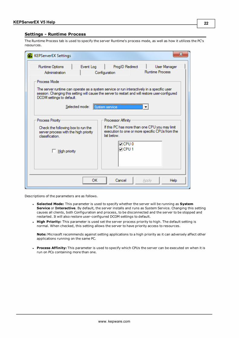
Settings - Runtime ProcessThe Runtime Process tab is used to specify the server Runtime's process mode, as well as how it utilizes the PC'sresources.
Descriptions of the parameters are as follows.
l Selected Mode: This parameter is used to specify whether the server will be running as SystemService or Interactive. By default, the server installs and runs as System Service. Changing this settingcauses all clients, both Configuration and process, to be disconnected and the server to be stopped andrestarted. It will also restore user-configured DCOM settings to default.
l High Priority: This parameter is used set the server process priority to high. The default setting isnormal. When checked, this setting allows the server to have priority access to resources.
Note: Microsoft recommends against setting applications to a high priority as it can adversely affect otherapplications running on the same PC.
l Process Affinity: This parameter is used to specify which CPUs the server can be executed on when it isrun on PCs containing more than one.
www. kepware.com
22

KEPServerEX V5 Help
Settings - Runtime OptionsThe Runtime Options tab is used to change settings in the project being executed in the Runtime.
Descriptions of the parameters are as follows:
l Use DCOM configuration utility settings: This parameter allows users to select authentication andalso launch and access security requirements through the DCOM Configuration Utility. In addition, userscan both specify the level of security to implement and restrict access for certain users and/orapplications.
When this setting is disabled, the server overrides the DCOM settings set for the application and does notperform any authentication on the calls received from client applications. It impersonates the security ofthe client when performing any actions on behalf of the client application. Disabling this setting providesthe lowest level of security and is not recommended. If this setting is chosen, ensure that the client andserver applications are running in a secure environment so that the application is not compromised.
l Backup the Runtime project prior to replacement: This parameter enables the Runtime project to bebacked up before it is overwritten. The backup location is displayed in the Event Log. This option isenabled by default.
Note: The Runtime project is overwritten if either New or Open is selected while connected to theRuntime. In addition, connecting to the Runtime while working offline with a project may result in Runtimeproject replacement.
l Keep the most recent: This parameter limits the number of backup files to be saved to disk. The rangeis 1 to 1000. The default is 10.
l Clean up now: This parameter invokes a confirmation dialog that allows users to delete all the Runtimeproject backups. Doing so does not affect the current running project.
www. kepware.com
23

KEPServerEX V5 Help
Settings - Event LogThe Event Log tab is used to define the communication and persistence settings for the Event Log, OPCDiagnostics Log, and Communications Diagnostics Log.
Note: The settings for each individual log type are independent of the settings for the other log types.
Descriptions of the parameters are as follows:
l Port: This parameter specifies the TCP/IP port to be used to communicate between the Log and theRuntime. The valid range is 49152 to 65535. To restore the default port setting, enter a blank value.
l Persistence Mode: This parameter specifies the log's persistence mode. Options include Memory, SingleFile, and Extended Datastore. The default setting for the Event Log Setting is Single File. The defaultsetting for both OPC Diagnostics Log Settings and Communications Diagnostics Log Settings is Memory(no persistence). Descriptions of the options are as follows:
l Memory (no persistence):When selected, this mode records all events in memory and doesnot generate a disk log. A specified number of records are retained before the oldest recordsstart being deleted. The contents are removed each time the server is started.
l Single File:When selected, this mode generates a single disk-based log file. A specifiednumber of records are retained before the oldest records start being deleted. The contents arerestored from this file on disk when the server is started.
l Extended Datastore:When selected, this mode persists a potentially large number of recordsto disk in a datastore distributed across many files. The records are retained for a specifiednumber of days before being removed from the disk. The contents are restored from thedistributed file store on disk when the server is started.
l Max. records: This parameter specifies the number of records that the log system retains before theoldest records start being deleted. It is only available when the Persistence Mode is set to Memory orSingle File. The valid range is 100 to 30000 records. The default setting is 1000 records.Note: The log is truncated if this parameter is set to a value less than the current size of the log.
www. kepware.com
24
KEPServerEX V5 Help
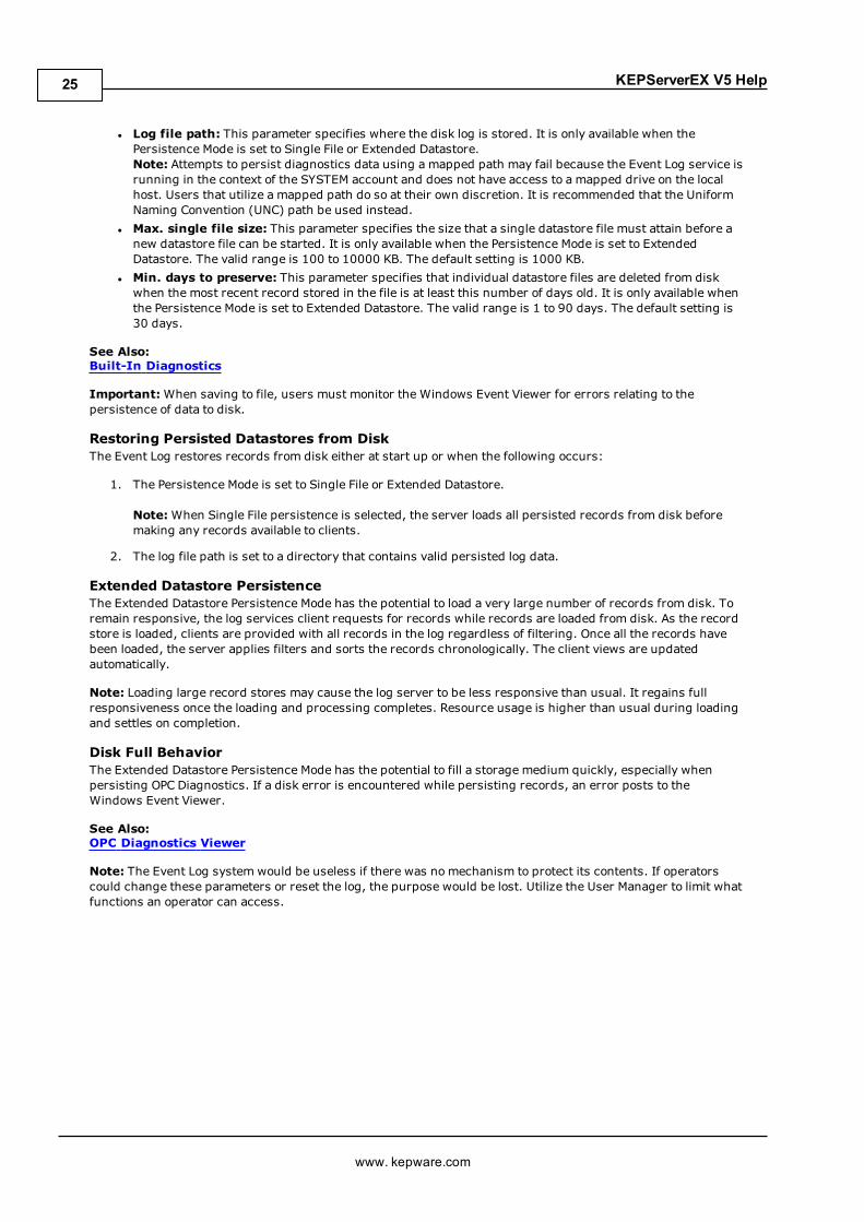
l Log file path: This parameter specifies where the disk log is stored. It is only available when thePersistence Mode is set to Single File or Extended Datastore.Note: Attempts to persist diagnostics data using a mapped path may fail because the Event Log service isrunning in the context of the SYSTEM account and does not have access to a mapped drive on the localhost. Users that utilize a mapped path do so at their own discretion. It is recommended that the UniformNaming Convention (UNC) path be used instead.
l Max. single file size: This parameter specifies the size that a single datastore file must attain before anew datastore file can be started. It is only available when the Persistence Mode is set to ExtendedDatastore. The valid range is 100 to 10000 KB. The default setting is 1000 KB.
l Min. days to preserve: This parameter specifies that individual datastore files are deleted from diskwhen the most recent record stored in the file is at least this number of days old. It is only available whenthe Persistence Mode is set to Extended Datastore. The valid range is 1 to 90 days. The default setting is30 days.
See Also:Built-In Diagnostics
Important:When saving to file, users must monitor the Windows Event Viewer for errors relating to thepersistence of data to disk.
Restoring Persisted Datastores from DiskThe Event Log restores records from disk either at start up or when the following occurs:
1. The Persistence Mode is set to Single File or Extended Datastore.
Note:When Single File persistence is selected, the server loads all persisted records from disk beforemaking any records available to clients.
2. The log file path is set to a directory that contains valid persisted log data.
Extended Datastore PersistenceThe Extended Datastore Persistence Mode has the potential to load a very large number of records from disk. Toremain responsive, the log services client requests for records while records are loaded from disk. As the recordstore is loaded, clients are provided with all records in the log regardless of filtering. Once all the records havebeen loaded, the server applies filters and sorts the records chronologically. The client views are updatedautomatically.
Note: Loading large record stores may cause the log server to be less responsive than usual. It regains fullresponsiveness once the loading and processing completes. Resource usage is higher than usual during loadingand settles on completion.
Disk Full BehaviorThe Extended Datastore Persistence Mode has the potential to fill a storage medium quickly, especially whenpersisting OPC Diagnostics. If a disk error is encountered while persisting records, an error posts to theWindows Event Viewer.
See Also:OPC Diagnostics Viewer
Note: The Event Log system would be useless if there was no mechanism to protect its contents. If operatorscould change these parameters or reset the log, the purpose would be lost. Utilize the User Manager to limit whatfunctions an operator can access.
www. kepware.com
25
KEPServerEX V5 Help
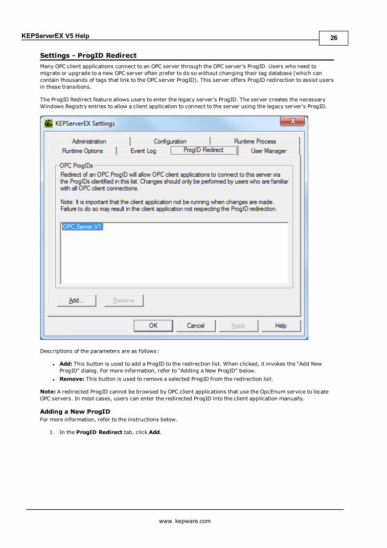
Settings - ProgID RedirectMany OPC client applications connect to an OPC server through the OPC server's ProgID. Users who need tomigrate or upgrade to a new OPC server often prefer to do so without changing their tag database (which cancontain thousands of tags that link to the OPC server ProgID). This server offers ProgID redirection to assist usersin these transitions.
The ProgID Redirect feature allows users to enter the legacy server's ProgID. The server creates the necessaryWindows Registry entries to allow a client application to connect to the server using the legacy server's ProgID.
Descriptions of the parameters are as follows:
l Add: This button is used to add a ProgID to the redirection list. When clicked, it invokes the "Add NewProgID" dialog. For more information, refer to "Adding a New ProgID" below.
l Remove: This button is used to remove a selected ProgID from the redirection list.
Note: A redirected ProgID cannot be browsed by OPC client applications that use the OpcEnum service to locateOPC servers. In most cases, users can enter the redirected ProgID into the client application manually.
Adding a New ProgIDFor more information, refer to the instructions below.
1. In the ProgID Redirect tab, click Add.
www. kepware.com
26
KEPServerEX V5 Help
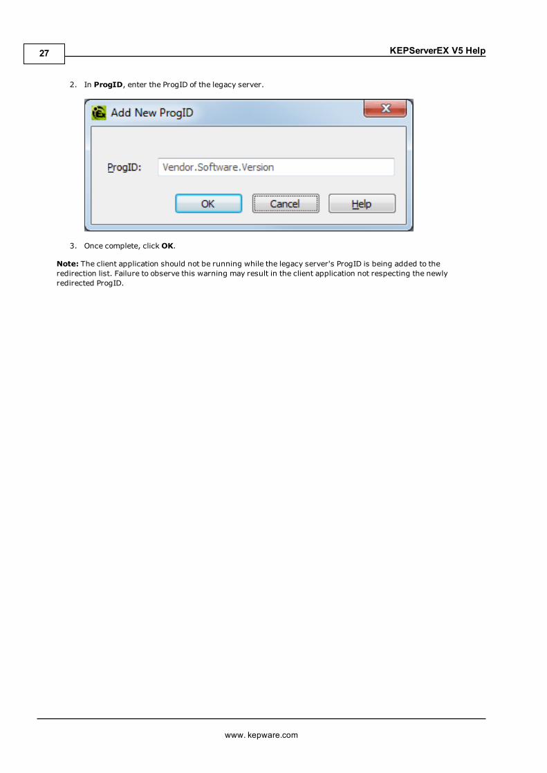
2. In ProgID, enter the ProgID of the legacy server.
3. Once complete, clickOK.
Note: The client application should not be running while the legacy server's ProgID is being added to theredirection list. Failure to observe this warning may result in the client application not respecting the newlyredirected ProgID.
www. kepware.com
27
KEPServerEX V5 Help
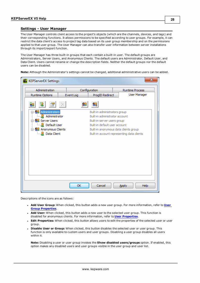
Settings - User ManagerThe User Manager controls client access to the project's objects (which are the channels, devices, and tags) andtheir corresponding functions. It allows permissions to be specified according to user groups. For example, it canrestrict the data client's access to project tag data based on its user group membership and on the permissionsapplied to that user group. The User Manager can also transfer user information between server installationsthrough its import/export function.
The User Manager has three built-in groups that each contain a built-in user. The default groups areAdministrators, Server Users, and Anonymous Clients. The default users are Administrator, Default User, andData Client. Users cannot rename or change the description fields. Neither the default groups nor the defaultusers can be disabled.
Note: Although the Administrator's settings cannot be changed, additional administrative users can be added.
Descriptions of the icons are as follows:
l Add User Group:When clicked, this button adds a new user group. For more information, refer toUserGroup Properties.
l Add User: When clicked, this button adds a new user to the selected user group. This function isdisabled for anonymous clients. For more information, refer toUser Properties.
l Edit Properties: When clicked, this button allows users to edit the properties of the selected user or usergroup.
l Disable User or Group:When clicked, this button disables the selected user or user group. Thisfunction is only available to custom users and user groups. Disabling a user group disables all userswithin it.
Note: Disabling a user or user group invokes the Show disabled users/groups option. If enabled, thisoption makes any disabled users and user groups visible in the user group and user list.
www. kepware.com
28

KEPServerEX V5 Help
l Restore User or group:When clicked, this button restores the selected user or user group. Restoring auser group returns the users within it to the state they were in prior to disabling. This icon is onlyavailable once a user or user group has been disabled.
Note: If all disabled users and user groups are restored, the Show disabled users/groups option is notdisplayed.
l Import User Information:When clicked, this button imports user information from an XML file. For theimport to succeed, the file that is selected must have been exported from the server's Administrationutility. This function is only enabled when the built-in Administrator is logged in.
l Export User Information: When clicked, this button exports user information to an XML file. This isuseful for users that need to move the project from one machine to another. Administrators also have theoption to password protect the XML file: if utilized, the correct password must be entered for the import tosucceed on the new machine. The XML file cannot be edited and then re-imported. This function isenabled at all times.
Important: The Import/Export User Information features were released in server version 5.12. Any userpasswords that were set while using previous server versions must be changed in 5.12 before an exportis attempted; otherwise, the export fails.
Note: Although custom users and user groups cannot be deleted once they have been created, the Import UserInformation option replaces existing users and user groups with those being imported (except for theAdministrator built-in user).
Important: For the sake of project preservation, it is recommended that users export a copy of the userinformation once it is complete. A project cannot load without correct user information.
Accessing Additional SettingsShortcuts and additional settings may be accessed through the context menus for user groups and users.
Description of the new user option is as follows:
www. kepware.com
29

KEPServerEX V5 Help
l Move User To: This option moves the user to a different user group. The status of the group does notmatter: both disabled and enabled groups appear in the list. An active user moved to a disabled groupbecomes disabled as well. A disabled user moved to an enabled group persists in status until changed.
User Group PropertiesThe user group properties may also be accessed by right-clicking on a user group and selecting Properties.
Note: To quickly allow or deny all options in a category, right-click on the category and select Allow All or DenyAll. A setting that displays bold text indicates that its value has been changed. Once the change is saved, the textdisplays as normal.
Descriptions of the parameters are as follows:
l Name: This parameter specifies the name of the new user group. The maximum number of charactersallowed is 31. Duplicate names are not allowed.
l Description: This optional parameter provides a brief description of the user group. This can beparticularly helpful for operators creating new user accounts. The maximum number of charactersallowed is 128.
l Permissions: This field assigns permissions for the selected user group. Permissions are organized intothe following categories: Project Modification, Server Permissions, I/O Tag Access, System Tag Access,Internal Tag Access, and Browse Project Namespace. More information on the categories is as follows:
www. kepware.com
30

KEPServerEX V5 Help
l Project Modification: This category specifies permissions that control default projectmodifications.
l Server Permissions: This category specifies permissions that control access to serverfunctionality. These permissions are not supported by the anonymous client.
l I/O Tag Access: This category specifies permissions that control access to device-level I/O tagdata. These tags require device communications, and are described as Static tags in the server.
l System Tag Access: This category specifies permissions that control access to System tags.These tags begin with an underscore and exist in a server-defined location. For moreinformation, refer to System Tags.
l Internal Tag Access: This category specifies permissions that control access to internal tags.These tags are either driver-managed (controlling some aspect of the driver's operation) oruser-specified (at a plug-in level).
l Browse Project Namespace: This category specifies permissions that control browse accessto the project namespace in clients that support browsing. This is only supported by a few clienttypes at this time.
Note: To view more information on a specific object in a category, select it.
Note: Users upgrading to the newest server version find that the Dynamic Addressing permissions are assignedthe default value Allow. Users with new installations are allowed to select the default value during installation.
User PropertiesThe user properties may also be accessed by right-clicking on the user and selecting Properties.
Descriptions of the parameters are as follows:
l Name: This parameter specifies the name of the user. The maximum number of characters allowed is 31.Duplicate names are not allowed, even if the user is being created in a different group.
l Description: This optional parameter provides a brief description of the user. This can be particularlyhelpful for operators. The maximum number of characters allowed is 128.
l Password: This field specifies the password that the user must enter to log into the system. It is case-sensitive, and must be entered the same in both the Password and Confirm fields. The maximum numberof characters allowed is 127.
l Confirm: This field confirms the password entered in the parameter above.
www. kepware.com
31
KEPServerEX V5 Help
Navigating the ConfigurationThe Configuration provides the general means of interacting with the server. While various plug-ins and driversadd buttons, menus, and icons, the standard interface elements are described below.
Menu BarFile Includes the project-level commands; such as Save, Open, Import, and Export.Edit Includes action commands; such as Copy, Paste, and New Channel.
View Includes the display commands; such as which elements of the user interface are visible or hiddenand the type of tree organization to display.
Tools Includes the configuration commands; such as general options, connection settings, and Event LogFilters.
Runtime Includes server connectivity commands; such as Connect..., Disconnect, and Reinitialize.Help Includes commands to access the product documentation, by server, driver, or plug-in.
Button BarThe standard buttons are described below:
New Project: Initiates creation of a new project file to replace the active project. The project filedefines the devices connected, their settings, and how they are grouped.Open Project: Allows the user to browse for an existing project file to load, replacing the activeproject.
Save Project: Implements any recent changes and writes the active project file to disk.
Save As: Writes the active project with changes, such as to a new location or file name.
Quick Client: Runs the integrated client interface.
View Selector
This drop-down menu specifies how the Project View and Detail View display. It is located in the toolbar andallows users to switch between the server's channels/devices and various supported plug-ins.
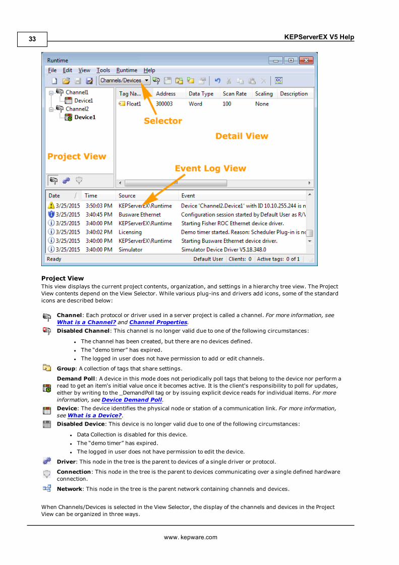
The main window is divided into three panes: the Project View, the Detail View, and the Event Log View,discussed below.
www. kepware.com
32
KEPServerEX V5 Help
Project ViewThis view displays the current project contents, organization, and settings in a hierarchy tree view. The ProjectView contents depend on the View Selector. While various plug-ins and drivers add icons, some of the standardicons are described below:
Channel: Each protocol or driver used in a server project is called a channel. For more information, seeWhat is a Channel? and Channel Properties.Disabled Channel: This channel is no longer valid due to one of the following circumstances:
l The channel has been created, but there are no devices defined.l The “demo timer” has expired.l The logged in user does not have permission to add or edit channels.
Group: A collection of tags that share settings.
Demand Poll: A device in this mode does not periodically poll tags that belong to the device nor perform aread to get an item's initial value once it becomes active. It is the client's responsibility to poll for updates,either by writing to the _DemandPoll tag or by issuing explicit device reads for individual items. For moreinformation, seeDevice Demand Poll.Device: The device identifies the physical node or station of a communication link. For more information,seeWhat is a Device?.Disabled Device: This device is no longer valid due to one of the following circumstances:
l Data Collection is disabled for this device.l The “demo timer” has expired.l The logged in user does not have permission to edit the device.
Driver: This node in the tree is the parent to devices of a single driver or protocol.
Connection: This node in the tree is the parent to devices communicating over a single defined hardwareconnection.
Network: This node in the tree is the parent network containing channels and devices.
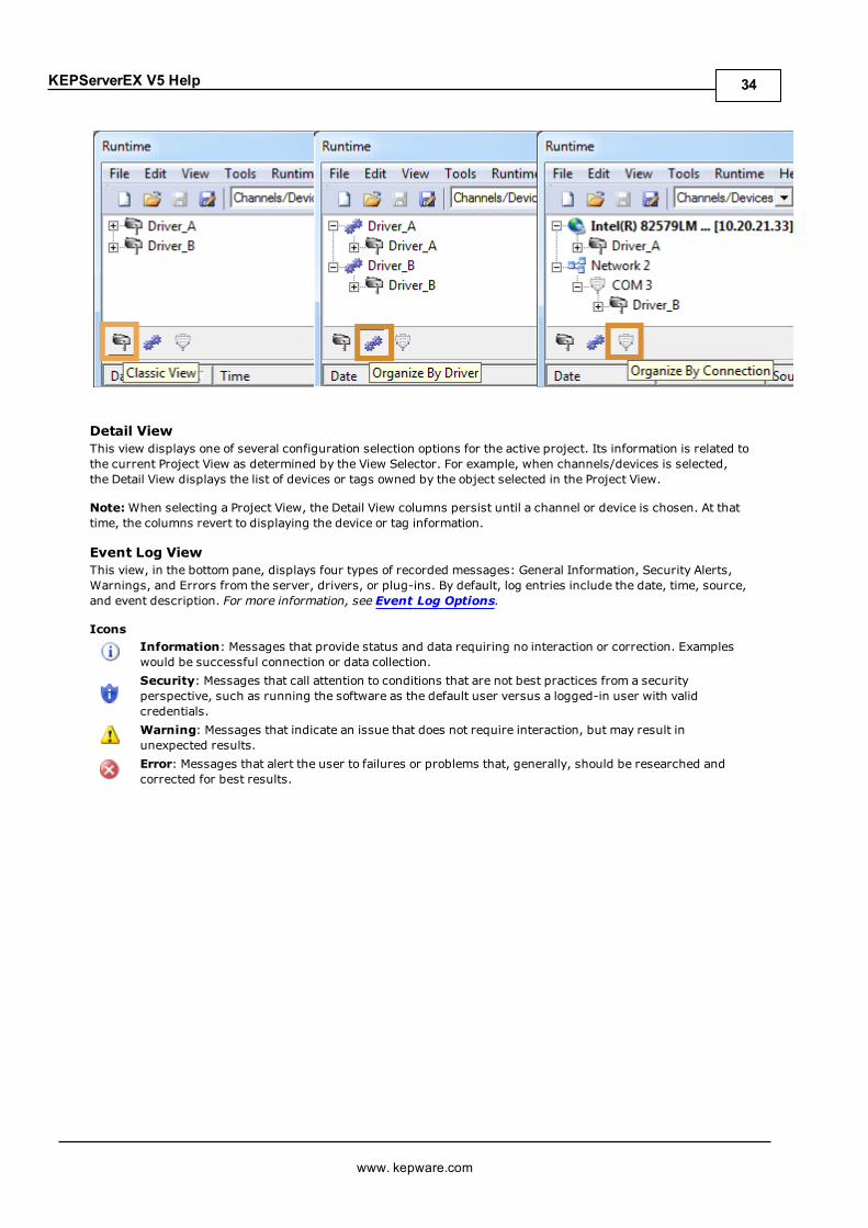
When Channels/Devices is selected in the View Selector, the display of the channels and devices in the ProjectView can be organized in three ways.
www. kepware.com
33
KEPServerEX V5 Help
Detail ViewThis view displays one of several configuration selection options for the active project. Its information is related tothe current Project View as determined by the View Selector. For example, when channels/devices is selected,the Detail View displays the list of devices or tags owned by the object selected in the Project View.
Note:When selecting a Project View, the Detail View columns persist until a channel or device is chosen. At thattime, the columns revert to displaying the device or tag information.
Event Log ViewThis view, in the bottom pane, displays four types of recorded messages: General Information, Security Alerts,Warnings, and Errors from the server, drivers, or plug-ins. By default, log entries include the date, time, source,and event description. For more information, see Event Log Options.
IconsInformation: Messages that provide status and data requiring no interaction or correction. Exampleswould be successful connection or data collection.Security: Messages that call attention to conditions that are not best practices from a securityperspective, such as running the software as the default user versus a logged-in user with validcredentials.Warning: Messages that indicate an issue that does not require interaction, but may result inunexpected results.Error: Messages that alert the user to failures or problems that, generally, should be researched andcorrected for best results.
www. kepware.com
34

KEPServerEX V5 Help
Project PropertiesTo access the Project Properties tabs from the configuration, click File | Project Properties. For moreinformation, select a link from the list below.
Project Properties - IdentificationProject Properties - OPC DA SettingsProject Properties - OPC DA ComplianceProject Properties - DDEProject Properties - FastDDE/SuiteLinkProject Properties - iFIX PDB SettingsProject Properties - OPC UAProject Properties - OPC AEProject Properties - OPC .NET
Project Properties - IdentificationThe Project Properties - Identification dialog is used to attach a title and comment to a project for reference.Although the Title field supports a string of up 64 characters, the Comments field has no practical limit. Limitingthe comment to the area available within the comment box, however, improves project load time.
Project Properties - OPC DA SettingsThis server supports the OPC Foundation's Data Access Specifications for 1.0, 2.0, and 3.0 simultaneously. Whilethis provides the utmost level of compatibility, there may be times when forcing the server to use one methodover another is necessary. The OPC DA Settings dialog is used to make these selections.
www. kepware.com
35

KEPServerEX V5 Help
Descriptions of the parameters are as follows:
l Enable OPC 1.0 data access interfaces: When checked, this option allows the server to accept OPCclient connections from OPC clients that support the 1.0 specification. The default setting is checked.
l Enable OPC 2.0 data access interfaces:When checked, this option allows the server to accept OPCclient connections from OPC clients that support the 2.0 specification. The default setting is checked.
l Enable OPC 3.0 data access interfaces: When checked, this option allows the server to accept OPCclient connections from OPC clients that support the 3.0 specification. The default setting is checked.
l Include hints when a client browses the server:When checked, this option allows OPC clientapplications to browse the address formatting Hints available for each communications driver. The Hintsprovide a visual quick reference on how a particular device's data can be addressed. This can be usefulwhen entering Dynamic tags from the OPC client. The hint items are not valid OPC tags. Some OPC clientapplications may try to add the Hint tags to their tag database. When this occurs, the client receives anerror from the server. This is not a problem for most clients, although it can cause others to stop addingtags automatically or report errors. Prevent this by turning the Hints On or Off. The default setting isunchecked.
l Include tag properties when a client browses the server:When checked, this option allows OPCclient applications to browse the tag properties available for each tag in the address space. The defaultsetting is unchecked.
l Enable diagnostics capture:When checked, this option allows OPC Diagnostics data to be captured andlogged to the Event Log service for storage. The default setting is unchecked.
l When notifying clients that the server is shutting down wait x seconds before disconnecting:This parameter specifies how long the server waits for an OPC client to return from the server shutdownevent. If the client application does not return within the timeout period, the server completes shutdownand exit. The valid range is 10 to 60 seconds. The default setting is 15 seconds.
l Wait x seconds before timing out on synchronous requests for data: This parameter specifieshow long the server waits for a synchronous read or write operation to complete. If a synchronousoperation is in progress and the timeout is exceeded, the server forces the operation to complete with afailure to the OPC client. This prevents OPC clients from locking up when using synchronous operations.The valid range is 5 to 60 seconds. The default setting is 15 seconds.
www. kepware.com
36

KEPServerEX V5 Help
Note: For more information on the OPC Data Access 1.0, 2.0, and 3.0 Custom Specifications, refer to the OPCFoundation websitewww.opcfoundation.org.
Project Properties - OPC DA ComplianceThis server has been designed to provide the highest level of compatibility with the OPC Foundation'sspecifications. In testing, however, it has been found that being fully-compatible with the specification andworking with all OPC client applications is a different matter. The OPC DA Compliance dialog allows users to tailorthe operation of the server to better meet the needs of rare OPC clients. These options seldom need to be adjustedfor the majority of OPC client applications.
Descriptions of the parameters are as follows:
l Perform the following operations: This option is the master enabling switch for the options present inthe list box. When enabled, the server sets all options to conform to OPC compliance. The default settingis disabled.
l Reject unsupported Language IDs:When checked, this option only allows Language IDs that arenatively supported by the server. If the OPC client application attempts to add an OPC group to the serverand receives a general failure, it is possible the client has given the server a Language ID that is notnatively supported. If this occurs, the server rejects the group addition. To resolve this particular issue,disable the compliant feature to force the server to accept any Language ID.
l Ignore deadband when returning data for cache needs:When checked, this option allows theserver to ignore the deadband setting on OPC groups added to the server. For some OPC clients, passingthe correct value for deadband causes problems that may result in the OPC client (such as, having gooddata even though it does not appear to be updating frequently or at all). This condition is rare. As such,the selection should normally be left in its default disabled state.
l Return all browse items regardless of read-write filter:When checked, this option causes theserver to return all tags to an OPC client application when a browse request is made, regardless of theaccess filter applied to the OPC clients tag browser.
l Data type support for 2.05a:When checked, this option causes the server to adhere to the data typerequirements and expected behaviors for data type coercion that were added to the 2.05a specification.
www. kepware.com
37

KEPServerEX V5 Help
l Return synchronous device read failure if one or more items would result in bad quality:When checked, this option causes the server to return a failure if one or more items for a synchronousdevice read results in a bad quality read. Compliance requires the server to return success, indicatingthat the server could complete the request even though the data for one or more items may include a badand/or uncertain quality.
l Return initial updates for items in a single callback:When checked, this option causes the serverto return all outstanding initial item updates in a single callback. When not selected, the server returnsinitial updates as they are available (which can result in multiple callbacks).Note: Enabling this setting may result in loss of buffered data when using drivers that support databuffering (Event Playback) for unsolicited device protocols. The compliance setting should be disabled ifloss of buffered data is a concern.
l Respect Language ID set by client when performing data type conversions:When checked, thisoption determines whether the server uses the Locale ID of the running Windows Operating System or theLocale ID set by the OPC client when performing data type conversions. For example, a stringrepresenting a floating point number such as 1,200 would be converted to One Thousand - TwelveHundred if converted using English metrics, but would be One and Two-Tenths if converted usingGerman metrics. If German software is running on an English OS, users need to determine how thecomma is handled. This setting allows for such flexibility. By default, and due to historicalimplementation, the server respects the Locale ID of the operating system.
l Data change callback is passed item-level error=S_FALSE for items with bad quality:Whenchecked, this option causes the server to return S_FALSE in the item error array for items without goodquality. This setting defaults to True for existing projects that are set to full compliance and False forthose that are not. When set to False, the legacy behavior of returning E_FAIL (0x80004005) occurs.
l Ignore group update rate, return data as soon as it becomes available:When checked, thisoption controls how all groups update their client. When enabled, an active item that experiences achange in value or quality triggers a client update. The group update rate specified by the client is used toset the client requested scan rate for the items added to that group. The default setting is unchecked.
Project Properties - DDEWhile the server is first and foremost an OPC server, there are still a number of applications that requireDynamic Data Exchange (DDE) to share data. The server provides access to DDE applications that supportone of the following DDE formats: CF_Text, XL_Table and Advanced DDE. CF_Text and XL_Table are standardDDE formats developed by Microsoft for use with all DDE aware applications. Advanced DDE is a highperformance format supported by a number of client applications specific to the industrial market.
Important: For the DDE interface to connect with the server, the Runtime must be allowed to interact with thedesktop. For more information, refer toHow To... Allow Desktop Interactions.
To access the DDE server settings through the Configuration, click File | Project Properties and then select theDDE tab. Its parameters can be used to tailor the DDE operation to fit the application's needs.
www. kepware.com
38

KEPServerEX V5 Help
Descriptions of the parameters are as follows:
l Enable DDE Connections to the Server: This parameter determines whether the DDE server portionof the server is enabled or disabled. If DDE operation is disabled, the server does not respond to anyrequest for DDE data. If intending to use the server only as an OPC server, users may want to disable DDEoperation. Doing so can increase the data security and improve overall server performance. DDE isdisabled by default.See Also: How To... Use DDE with the Server
l Enable Net DDE: This parameter determines whether Microsoft's Net DDE services are enabled ordisabled. If intending to use the server only with local DDE client applications, users should keep Net DDEdisabled (the default setting). Starting the Net DDE services can be a time consuming process that canslow the startup of the server. If users do need to use Net DDE, enabling it causes the server toautomatically register its share names and start the Net DDE service manager. DDE shares are removedwhen the server shuts down.See Also: How To... Use Net DDE with the Server
l Service Name: This parameter allows users to change how the server appears as an application name toDDE clients. This name is initially set to allow compatibility with the previous versions of the server. Ifusers need to replace an existing DDE server however, the server's service name can be changed tomatch the DDE server being replaced. The service name allows a string of 1 to 32 characters to beentered.
l Formats: This parameter allows users to configure the DDE format to provide to client applications.Options include Advanced DDE, XL Table, and CF_Text. All three formats are enabled by default. This isparticularly useful when users experience problems connecting a DDE client application to the server:each of the DDE formats can be disabled to isolate a specific format for testing purposes.Note: Every DDE-aware application must support CF_Text at a minimum.
l Update active clients: This interval setting is used to batch up DDE data so that it can be transferred toclient applications. When using a DDE format performance gains only come when large blocks of serverdata can be sent in a single DDE response. To improve the ability of the server to gather a large block ofdata, the update timer can be set to allow a pool of new data to accumulate before a being sent to a clientapplication. The valid range of the update timer is 20 to 60000 milliseconds. The default setting is 100milliseconds.
www. kepware.com
39

KEPServerEX V5 Help
l Wait: This parameter is used to configure a timeout for the completion of DDE request. If a DDE clientrequest (either a read or write operation) on the server cannot be completed within the specified timeout,an error is returned to the DDE client. The valid range is 1 to 30 seconds. The default setting is 15seconds.
Note: The server Runtime may have to be reinitialized for changes to take effect.
Project Properties - FastDDE/SuitelinkThe server's support of Wonderware Corporation's FastDDE and SuiteLink simplifies the task of connecting theserver with FactorySuite applications. The Wonderware connectivity toolkit is used to simultaneously provide OPCand FastDDE/SuiteLink connectivity while allowing for quick access to device data without the use of intermediarybridging software.
Important: For the FastDDE interface to connect with the server, the Runtime must be allowed to interact withthe desktop. For more information, refer toHow To... Allow Desktop Interactions.
Note: For proper FastDDE/SuiteLink operation (and for this tab to be displayed in Project Properties), theWonderware FS2000 Common Components or the InTouch Runtime Component version 8.0 or higher must beinstalled on the PC.
Descriptions of the parameters are as follows:
l Enable FastDDE/SuiteLink connections to the server: This parameter enables or disables supportof the client/server protocols. When a Wonderware product is installed on the PC, this setting is enabledby default. If the FastDDE/SuiteLink operation is disabled, the server does not respond to any request forFastDDE or SuiteLink data. For better performance and security, it is recommended that this setting bedisabled if the server is only used for OPC connectivity.
l Application name: This parameter specifies the application's name. The default setting is "server_runtime".
Note: This namemay be customized to suit specific end-user needs. For example, users that select
www. kepware.com
40
KEPServerEX V5 Help
"Remove and Redirect" during the installation must change this setting to "servermain" for certainFactorySuite applications to work without modification.
l Update active clients every x ms: This parameter specifies how often new data is sent toFastDDE/SuiteLink client applications. The range is 20 to 32000 milliseconds. The default setting is 100milliseconds. The timer allows FastDDE/SuiteLink data to be batched up for transfer to client applications.When using a client/server protocol like FastDDE or SuiteLink, performance gains only come when largeblocks of server data can be sent in a single response. To improve the ability of the server to gather alarge block of data, the update timer can be set to allow a pool of new data to accumulate before beingsent to a client application.
Note: The update rate applies to how often data is sent to the client application, not how often data isread from the device. The scan rate can be used to adjust how fast or slow the server acquires data froman attached device. For more information, refer to Tag Properties - General.
l Restore Defaults:When pressed, this button restores the settings described above to their defaultvalues.
Note: The server Runtime may have to be reinitialized for changes to take effect.
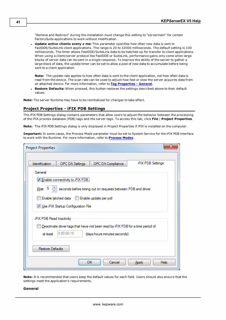
Project Properties - iFIX PDB SettingsThe iFIX PDB Settings dialog contains parameters that allow users to adjust the behavior between the processingof the iFIX process database (PDB) tags and the server tags. To access this tab, click File | Project Properties.
Note: The iFIX PDB Settings dialog is only displayed in Project Properties if iFIX is installed on the computer.
Important: In some cases, the Process Mode parameter must be set to System Service for the iFIX PDB interfaceto work with the Runtime. For more information, refer to Process Modes.
Note: It is recommended that users keep the default values for each field. Users should also ensure that thesettings meet the application's requirements.
General
www. kepware.com
41

KEPServerEX V5 Help
l Enable connectivity to iFIX PDB: This parameter is used to enable or disable support of theclient/server protocols. If the iFIX PDB operation is disabled, the server does not respond to any requestfor iFIX PDB data. For better performance and security when the server is only being used for OPCconnectivity, disable this parameter.
l Wait x seconds before timing out on requests between PDB and driver: This parameter specifiesthe amount of time that the iFIX PDB waits for a response from an add, remove, read, or write requestbefore timing out. Once timed out, the request is discarded on behalf of the server. A timeout can occur ifthe server is busy processing other requests or if the server has lost communications with iFIX PDB. Inthe case of lost communications, the iFIX PDB automatically re-establishes communications with theserver so that successive timeouts do not occur. The valid range is 5 to 60 seconds. The default setting is5 seconds.
l Enable latched data: Normally, the iFIX application's data links display a series of question marks (suchas "????") if a communication failure has occurred. Users may want to have a value displayed at all times,however. By enabling latched data, the last value successfully read is preserved on the screen. Thedefault setting is checked.Note: Data latching is not supported for AR and DR blocks.
l Enable update per poll:When checked, the server delivers the current value, quality, and timestamp toiFIX every time that the driver polls the device. When unchecked, the server only delivers an update toiFIX when it determines the value or the quality has changed. The default setting is unchecked.Note: This setting is dynamic, meaning that the server immediately begins to deliver updates to the iFIXclient at the device scan rate after the option is applied.
l Use iFIX Startup Configuration File:When checked, this file is created by iFIX and contains all itemsaccessed by the iFIX client. It automatically starts scanning items before iFIX requests item data. Thedefault setting is checked.See Also: Project Startup for iFIX Applications
iFIX PDB Read InactivityThis parameter allows the server to automatically deactivate tags that have not been read by iFIX for the timeperiod specified. This reduces unnecessary polling of the process hardware. When iFIX PDB Read Inactivityfeature is enabled, the server reads its list of tags every 15 seconds and deactivates any that are idle. If iFIX hasnot performed a read request of a tag for the time period specified, the tag is considered idle. Since the serverchecks for idle tags on a 15 second cycle, a tag may not get set inactive at precisely this time from its last read; itcould be up to 15 seconds longer depending on when the last read occurred in the check cycle. If iFIX requestsdata from a tag that has been previously deactivated, the server reactivates the tag and resumes polling thehardware. The default setting is unchecked. Once this feature is enabled, however, it becomes applied to allprojects. Users may specify an idle time of up to 6:23:59:59 (1 week). The time period can also be specified inseconds. For example, if 62 is entered, the page shows 0:00:01:02 when accessed next.
Caution: This feature is meant to be used with Register tags only and can cause non-register tags to go off scan.To avoid this situation when using this feature, set the inactivity timer greater than the longest scan timeconfigured in the iFIX database.
Format Range Default Value[days:hours:minutes:seconds] 0:00:00:15 to 6:23:59:59 0:00:00:15 (15 seconds)
ExamplesTime Format20 seconds 0:00:00:20 or 201 minute 0:00:01:00 or 601 hour and 30 minutes 0:01:30:00 or 54002 days 2:00:00:00
Restore DefaultsWhen pressed, this button restores the settings described above to their default values.
Project Properties - OPC UAOPC Unified Architecture (UA) provides a platform independent interoperability standard. It is not a replacementfor OPC Data Access (DA) technologies: for most industrial applications, UA complements or enhances an existingDA architecture. The OPC UA tab displays the current OPC UA settings in the server.
Note: To change a setting, click in the specific parameter's second column. This invokes a drop-down menu thatdisplays the options available.
www. kepware.com
42
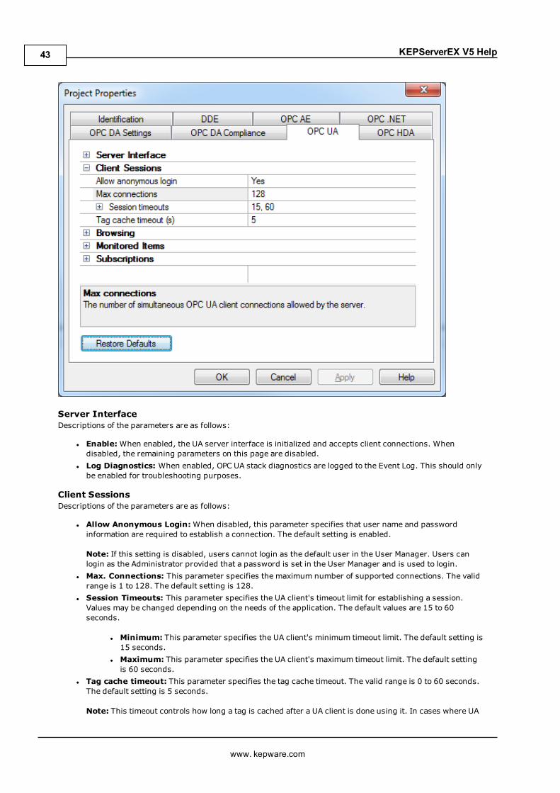
KEPServerEX V5 Help
Server InterfaceDescriptions of the parameters are as follows:
l Enable:When enabled, the UA server interface is initialized and accepts client connections. Whendisabled, the remaining parameters on this page are disabled.
l Log Diagnostics: When enabled, OPC UA stack diagnostics are logged to the Event Log. This should onlybe enabled for troubleshooting purposes.
Client SessionsDescriptions of the parameters are as follows:
l Allow Anonymous Login:When disabled, this parameter specifies that user name and passwordinformation are required to establish a connection. The default setting is enabled.
Note: If this setting is disabled, users cannot login as the default user in the User Manager. Users canlogin as the Administrator provided that a password is set in the User Manager and is used to login.
l Max. Connections: This parameter specifies the maximum number of supported connections. The validrange is 1 to 128. The default setting is 128.
l Session Timeouts: This parameter specifies the UA client's timeout limit for establishing a session.Values may be changed depending on the needs of the application. The default values are 15 to 60seconds.
l Minimum: This parameter specifies the UA client's minimum timeout limit. The default setting is15 seconds.
l Maximum: This parameter specifies the UA client's maximum timeout limit. The default settingis 60 seconds.
l Tag cache timeout: This parameter specifies the tag cache timeout. The valid range is 0 to 60 seconds.The default setting is 5 seconds.
Note: This timeout controls how long a tag is cached after a UA client is done using it. In cases where UA
www. kepware.com
43
KEPServerEX V5 Help
clients read/write to unregistered tags at a set interval, users can improve performance by increasing thetimeout. For example, if a client is reading an unregistered tag every 5 seconds, the tag cache timeoutshould be set to 6 seconds. Since the tag does not have to be recreated during each client request,performance improves.
BrowsingDescriptions of the parameters are as follows:
l Return Tag Properties: When enabled, this parameter allows UA client applications to browse the tagproperties available for each tag in the address space. This setting is disabled by default.
l Return Address Hints: When enabled, this parameter allows UA client applications to browse theaddress formatting hints available for each item. Although the hints are not valid UA tags, certain UAclient applications may try to add them to the tag database. When this occurs, the client receives an errorfrom the server. This may cause the client to report errors or stop adding the tags automatically. Toprevent this from occurring, make sure that this parameter is disabled. This setting is disabled bydefault.
Monitored ItemsDescription of the parameter is as follows:
l Max. Data Queue Size: This parameter specifies the maximum number of data notifications to bequeued for an item. The valid range is 1 to 100. The default setting is 2.
Note: The data queue is used when the monitored item's update rate is faster than the subscription'spublish rate. For example, if the monitored item update rate is 1 second, and a subscription publishesevery 10 seconds, then 10 data notifications are published for the item every 10 seconds. Becausequeuing data consumes memory, this value should be limited when memory is a concern.
SubscriptionsDescriptions of the parameters are as follows:
l Max. Retransmit Queue Size: This parameter specifies the maximum number of publishes to bequeued per subscription. The valid range is 1 to 100. A value of zero disables retransmits. The defaultsetting is 0.
Note: Subscription publish events are queued and retransmitted at the client's request. Because queuingconsumes memory, this value should be limited when memory is a concern.
l Max. Notifications Per Publish: This parameter specifies the maximum number of notifications perpublish. The valid range is 1 to 65536. The default setting is 65536.
Note: This value may affect the connection's performance by limiting the size of the packets sent from theserver to the client. In general, large values should be used for high-bandwidth connections and smallvalues should be used for low-bandwidth connections.
Note: For more information on OPC UA, refer to the OPC UA Configuration Manager help file.
Project Properties - OPC AEEvents are used to signal an occurrence in the server and are similar to data updates in OPC Data Access. TheOPC AE functionality allows users to receive Simple Events from the server, including system startup andshutdown messages, warnings, errors, and so forth. These events are then displayed in the Event Log.
The OPC AE tab is used to specify a number of project-level AE settings. Changes made to these settings takeeffect after all A&E clients disconnect from the server.
Note: The Alarms & Events Plug-In allows Alarms & Events (A&E) clients to receive A&E data from the OPCserver. It is used to convert OPC server events into A&E format and to create custom alarms using OPC servertags. For more information, contact the OPC vendor.
www. kepware.com
44

KEPServerEX V5 Help
Descriptions of the parameters are as follows:
l Enable AE Connections to the Server: This parameter turns the OPC AE server on and off.l Enable Simple Events:When checked, simple events are made available to clients. When unchecked,the events are sent. The default setting is checked.
l Max. Subscription Buffer Size: This parameter specifies the maximum number of events that the A&EPlug-In sends to a client in one send call. The range is 0 to 65534. The default setting is 100. 0 meansthere is no limit.
l Min. Subscription Buffer Time: This parameter specifies the minimum time between send calls to aclient. The supported range is 1000 to 60000 milliseconds. The default setting is 1000 milliseconds.
l Min. Keep-Alive Time: This parameter specifies the minimum amount of time between keep-alivemessages sent from the server to the client. The default setting is 1000 milliseconds.
l Restore Defaults:When pressed, this button reverts the settings described above to their last appliedstate.
www. kepware.com
45
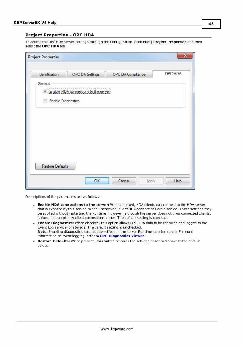
KEPServerEX V5 Help
Project Properties - OPC HDATo access the OPC HDA server settings through the Configuration, click File | Project Properties and thenselect theOPC HDA tab.
Descriptions of the parameters are as follows:
l Enable HDA connections to the server:When checked, HDA clients can connect to the HDA serverthat is exposed by this server. When unchecked, client HDA connections are disabled. These settings maybe applied without restarting the Runtime; however, although the server does not drop connected clients,it does not accept new client connections either. The default setting is checked.
l Enable Diagnostics:When checked, this option allows OPC HDA data to be captured and logged to theEvent Log service for storage. The default setting is unchecked.Note: Enabling diagnostics has negative effect on the server Runtime's performance. For moreinformation on event logging, refer toOPC Diagnostics Viewer.
l Restore Defaults:When pressed, this button restores the settings described above to the defaultvalues.
www. kepware.com
46

KEPServerEX V5 Help
Project Properties - OPC .NETTo access the OPC .NET server settings through the Configuration, click File | Project Properties and thenselect theOPC .NET tab.
Descriptions of the parameters are as follows:
l Enable:When checked, the OPC .NET Wrapper is initialized and accept client connections.l Restore Defaults:When pressed, this button restores the setting described above to its default value.
Notes:
1. The OPC .NET Wrapper runs as a System Service called "xi_server_runtime.exe". It is only started whenthe server starts and the option described above is enabled. Unlike OPC DA, clients cannot launch theserver.
2. To use and install OPC .NET, Microsoft .NET 3.5 must be present on the machine prior to serverinstallation.
www. kepware.com
47

KEPServerEX V5 Help
Server OptionsTo access the Server Options tabs from the configuration, click Tools | Options. These settings are configuredon an individual basis. For more information, select a link from the list below.
Options - GeneralOptions - Runtime Connection
Options - GeneralThis dialog is used to specify general server options (such as when to establish a connection with the Runtime,when to back up saved Configuration project files, and what conditions invoke warning pop-ups).
Descriptions of the parameters are as follows:
l Immediately attempt to establish a Runtime connection on start: This parameter specifieswhether the configuration tool connects to the Runtime when started. When unchecked, users mustconnect manually. The default setting is checked.
l Keep track of the __ most recently used project files: This parameter specifies how many projectfiles are presented in theMRU (Most Recently Used) list of projects. The valid range is 1 to 16. Thedefault setting is 8.
l Backup saved Configuration project files prior to overwriting:When checked, the systemautomatically makes a backup copy of the last saved Configuration project before it is overwritten with anew project file. The backup file's name and location are displayed in the Event Log.
l CSV Import: TheDelimiter setting specifies the Comma Separated Variable (CSV) that the server usesto import and export tag data in a CSV file. Options include comma and semicolon. The default setting iscomma. For more information, refer to Tag Management.
l Confirmations: This parameter specifies the conditions that force the Configuration to present warningpop-ups to an operator. Descriptions of the options are as follows:
l Deleting an object:When enabled, all Configuration delete operations invoke a warning popupthat requires confirmation before the delete operation can be completed.
www. kepware.com
48
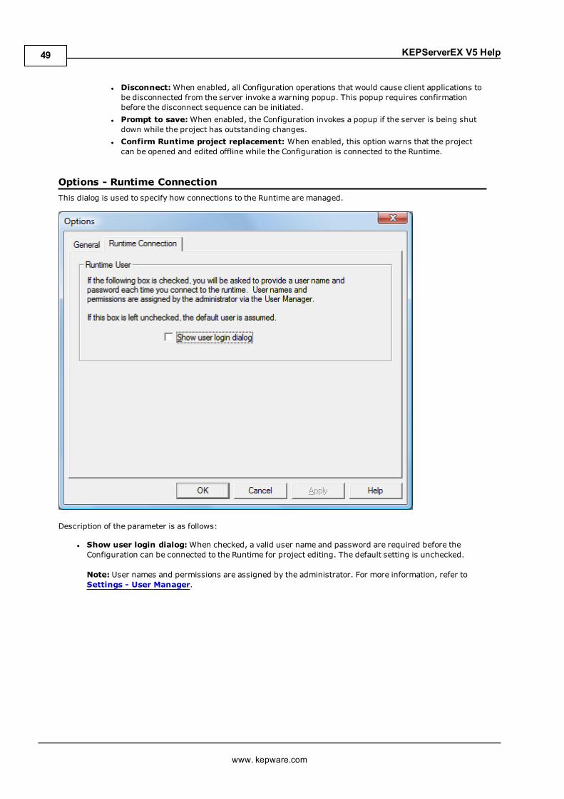
KEPServerEX V5 Help
l Disconnect:When enabled, all Configuration operations that would cause client applications tobe disconnected from the server invoke a warning popup. This popup requires confirmationbefore the disconnect sequence can be initiated.
l Prompt to save:When enabled, the Configuration invokes a popup if the server is being shutdown while the project has outstanding changes.
l Confirm Runtime project replacement: When enabled, this option warns that the projectcan be opened and edited offline while the Configuration is connected to the Runtime.
Options - Runtime ConnectionThis dialog is used to specify how connections to the Runtime are managed.
Description of the parameter is as follows:
l Show user login dialog:When checked, a valid user name and password are required before theConfiguration can be connected to the Runtime for project editing. The default setting is unchecked.
Note: User names and permissions are assigned by the administrator. For more information, refer toSettings - User Manager.
www. kepware.com
49
KEPServerEX V5 Help
Basic Server ComponentsFor more information on a specific server component, select a link from the list below.
What is a Channel?What is a Device?What is a Tag?What is a Tag Group?What is the Alias Map?What is the Event Log?
What is a Channel?A channel represents a communication medium from the PC to one or more external devices. A channel can beused to represent a serial port, a card installed in the PC or an Ethernet socket.
Before adding devices to a project, users must define the channel to be used when communicating with devices.A channel and a device driver are closely tied. After creating a channel, only devices that the selected driversupports can be added to this channel.
Adding a ChannelChannels are added using the channel wizard, which guide users through the channel definition process. Tostart, users are prompted for a logical name to assign the channel. This namemust be unique among all channelsand devices defined in the project. For information on reserved characters, refer toHow To... Properly Name aChannel, Device, Tag, and Tag Group.
Next, users are prompted for the device driver to be used. A list box is presented that displays all of the devicedrivers currently installed in the system. All serial drivers can be used with multiple channels in the sameproject.
Note: For hardware card drivers, refer to the driver's help documentation to determine the ability to use withmultiple channels in a single project. For information on how to determine the number of supported channels,refer to Server Summary Information.
Users are prompted for the specific communication parameters to be used. Multiple channels cannot shareidentical communication parameters; for example, two serial drivers cannot use COM1. For the correctcommunication parameters of a particular device, refer to both the manufacturer's and the driver's helpdocumentation.
Note: Flow Control settings for serial drivers are primarily used when connecting RS422/485 network devices tothe RS232 serial port via a converter. Most RS232 to RS422/485 converters require either no flow control (None)or that the RTS line be on when the PC is transmitting and off when listening (RTS).
The channel wizard finishes with a summary of the new channel.
Removing a ChannelTo remove a channel from the project, select the desired channel and then press theDelete key. Alternatively,select Edit | Delete from the Edit menu or toolbar.
Displaying Channel PropertiesTo display the channel properties of a specific channel, select the channel and then click Edit | Properties fromthe Edit menu or toolbar.
See Also:Channel Properties - General
Channel Properties - GeneralEach protocol or driver used in a server project is called a channel. A server project may consist of manychannels with the same communications driver or with unique communications drivers.
www. kepware.com
50
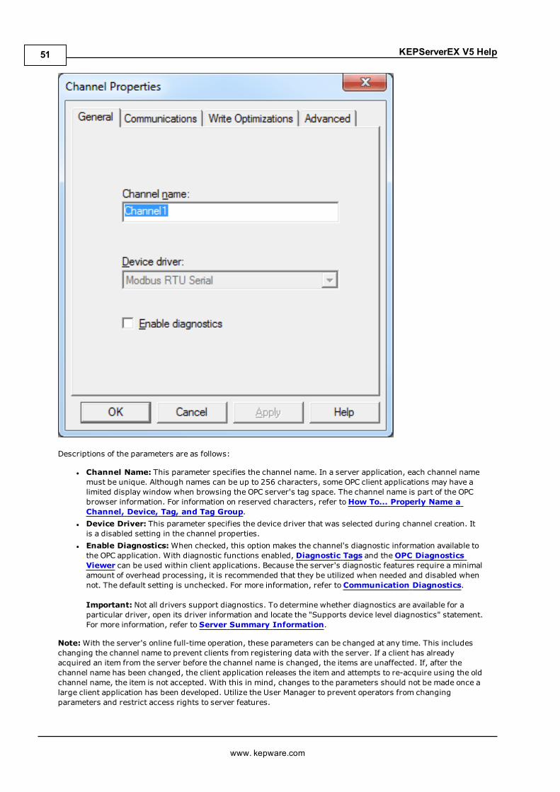
KEPServerEX V5 Help
Descriptions of the parameters are as follows:
l Channel Name: This parameter specifies the channel name. In a server application, each channel namemust be unique. Although names can be up to 256 characters, some OPC client applications may have alimited display window when browsing the OPC server's tag space. The channel name is part of the OPCbrowser information. For information on reserved characters, refer toHow To... Properly Name aChannel, Device, Tag, and Tag Group.
l Device Driver: This parameter specifies the device driver that was selected during channel creation. Itis a disabled setting in the channel properties.
l Enable Diagnostics:When checked, this option makes the channel's diagnostic information available tothe OPC application. With diagnostic functions enabled, Diagnostic Tags and theOPC DiagnosticsViewer can be used within client applications. Because the server's diagnostic features require a minimalamount of overhead processing, it is recommended that they be utilized when needed and disabled whennot. The default setting is unchecked. For more information, refer to Communication Diagnostics.
Important: Not all drivers support diagnostics. To determine whether diagnostics are available for aparticular driver, open its driver information and locate the "Supports device level diagnostics" statement.For more information, refer to Server Summary Information.
Note:With the server's online full-time operation, these parameters can be changed at any time. This includeschanging the channel name to prevent clients from registering data with the server. If a client has alreadyacquired an item from the server before the channel name is changed, the items are unaffected. If, after thechannel name has been changed, the client application releases the item and attempts to re-acquire using the oldchannel name, the item is not accepted. With this in mind, changes to the parameters should not be made once alarge client application has been developed. Utilize the User Manager to prevent operators from changingparameters and restrict access rights to server features.
www. kepware.com
51

KEPServerEX V5 Help
See Also:Channel Properties - CommunicationChannel Properties - Write OptimizationChannel Properties - AdvancedChannel Properties - Communication Serialization
Channel Properties - CommunicationsThe Communications tab varies depending on the driver and connection type selected. The connection typespecifies the type of hardware device for data communications. Options include COM Port, None, Modem, andEthernet Encapsulation. The default setting is COM Port. For more information on the parameters available for aspecific connection type, select a link from the list below.
NoneCOM PortModemEthernet Encapsulation
Note: These parameters are only available to serial drivers.
None
Description of the parameter is as follows:
www. kepware.com
52
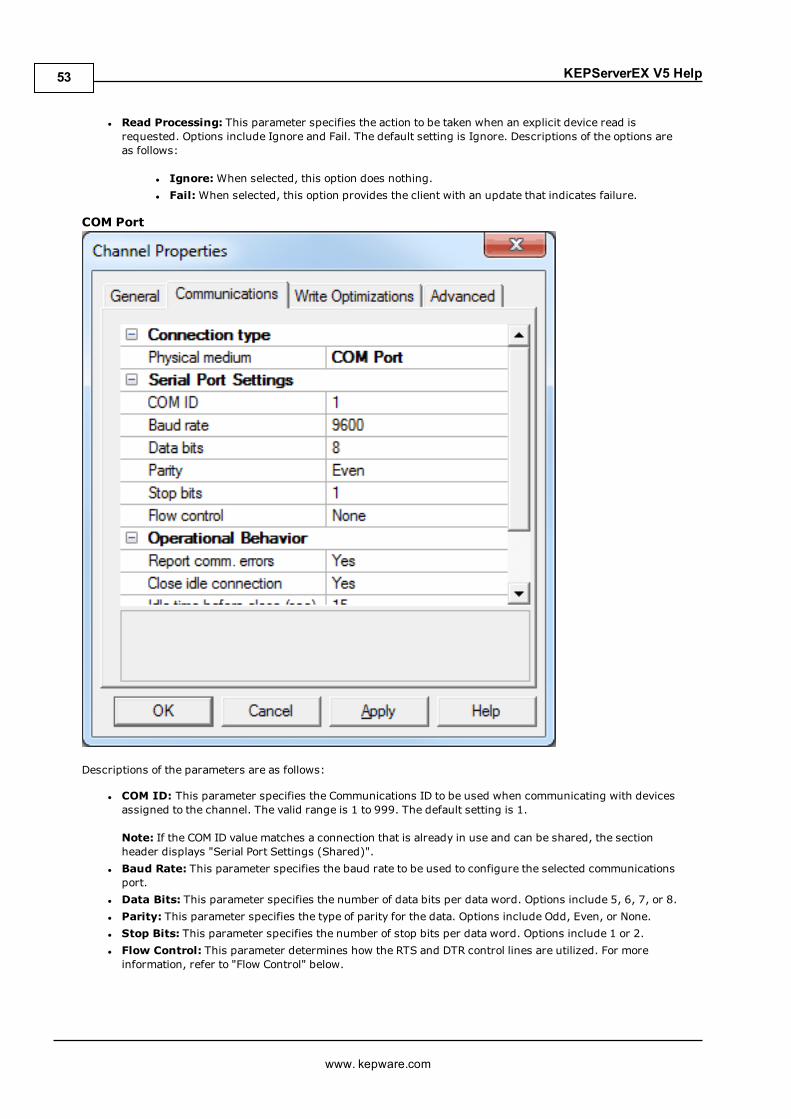
KEPServerEX V5 Help
l Read Processing: This parameter specifies the action to be taken when an explicit device read isrequested. Options include Ignore and Fail. The default setting is Ignore. Descriptions of the options areas follows:
l Ignore:When selected, this option does nothing.l Fail:When selected, this option provides the client with an update that indicates failure.
COM Port
Descriptions of the parameters are as follows:
l COM ID: This parameter specifies the Communications ID to be used when communicating with devicesassigned to the channel. The valid range is 1 to 999. The default setting is 1.
Note: If the COM ID value matches a connection that is already in use and can be shared, the sectionheader displays "Serial Port Settings (Shared)".
l Baud Rate: This parameter specifies the baud rate to be used to configure the selected communicationsport.
l Data Bits: This parameter specifies the number of data bits per data word. Options include 5, 6, 7, or 8.l Parity: This parameter specifies the type of parity for the data. Options include Odd, Even, or None.l Stop Bits: This parameter specifies the number of stop bits per data word. Options include 1 or 2.l Flow Control: This parameter determines how the RTS and DTR control lines are utilized. For moreinformation, refer to "Flow Control" below.
www. kepware.com
53
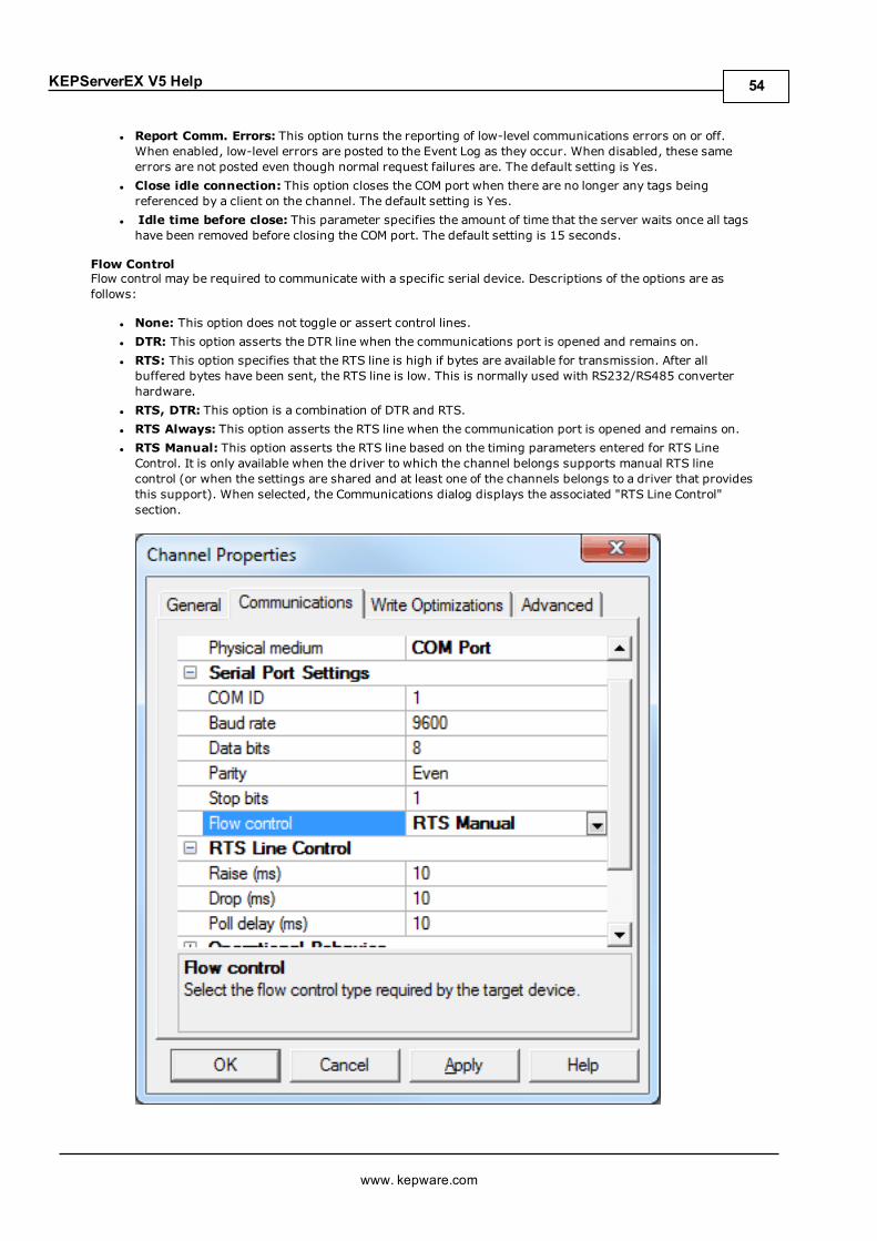
KEPServerEX V5 Help
l Report Comm. Errors: This option turns the reporting of low-level communications errors on or off.When enabled, low-level errors are posted to the Event Log as they occur. When disabled, these sameerrors are not posted even though normal request failures are. The default setting is Yes.
l Close idle connection: This option closes the COM port when there are no longer any tags beingreferenced by a client on the channel. The default setting is Yes.
l Idle time before close: This parameter specifies the amount of time that the server waits once all tagshave been removed before closing the COM port. The default setting is 15 seconds.
Flow ControlFlow control may be required to communicate with a specific serial device. Descriptions of the options are asfollows:
l None: This option does not toggle or assert control lines.l DTR: This option asserts the DTR line when the communications port is opened and remains on.l RTS: This option specifies that the RTS line is high if bytes are available for transmission. After allbuffered bytes have been sent, the RTS line is low. This is normally used with RS232/RS485 converterhardware.
l RTS, DTR: This option is a combination of DTR and RTS.l RTS Always: This option asserts the RTS line when the communication port is opened and remains on.l RTS Manual: This option asserts the RTS line based on the timing parameters entered for RTS LineControl. It is only available when the driver to which the channel belongs supports manual RTS linecontrol (or when the settings are shared and at least one of the channels belongs to a driver that providesthis support). When selected, the Communications dialog displays the associated "RTS Line Control"section.
www. kepware.com
54
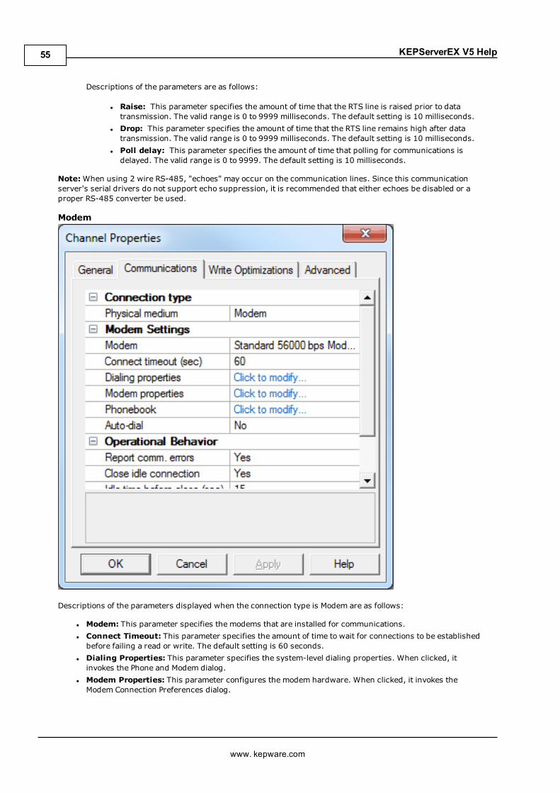
KEPServerEX V5 Help
Descriptions of the parameters are as follows:
l Raise: This parameter specifies the amount of time that the RTS line is raised prior to datatransmission. The valid range is 0 to 9999 milliseconds. The default setting is 10 milliseconds.
l Drop: This parameter specifies the amount of time that the RTS line remains high after datatransmission. The valid range is 0 to 9999 milliseconds. The default setting is 10 milliseconds.
l Poll delay: This parameter specifies the amount of time that polling for communications isdelayed. The valid range is 0 to 9999. The default setting is 10 milliseconds.
Note:When using 2 wire RS-485, "echoes" may occur on the communication lines. Since this communicationserver's serial drivers do not support echo suppression, it is recommended that either echoes be disabled or aproper RS-485 converter be used.
Modem
Descriptions of the parameters displayed when the connection type is Modem are as follows:
l Modem: This parameter specifies the modems that are installed for communications.l Connect Timeout: This parameter specifies the amount of time to wait for connections to be establishedbefore failing a read or write. The default setting is 60 seconds.
l Dialing Properties: This parameter specifies the system-level dialing properties. When clicked, itinvokes the Phone and Modem dialog.
l Modem Properties: This parameter configures the modem hardware. When clicked, it invokes theModem Connection Preferences dialog.
www. kepware.com
55
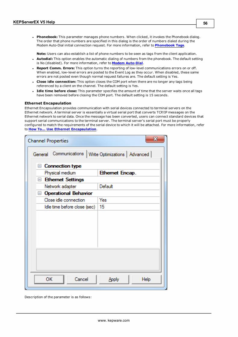
KEPServerEX V5 Help
l Phonebook: This parameter manages phone numbers. When clicked, it invokes the Phonebook dialog.The order that phone numbers are specified in this dialog is the order of numbers dialed during theModem Auto-Dial initial connection request. For more information, refer to Phonebook Tags.
Note: Users can also establish a list of phone numbers to be seen as tags from the client application.l Autodial: This option enables the automatic dialing of numbers from the phonebook. The default settingis No (disabled). For more information, refer toModem Auto-Dial.
l Report Comm. Errors: This option turns the reporting of low-level communications errors on or off.When enabled, low-level errors are posted to the Event Log as they occur. When disabled, these sameerrors are not posted even though normal request failures are. The default setting is Yes.
l Close idle connection: This option closes the COM port when there are no longer any tags beingreferenced by a client on the channel. The default setting is Yes.
l Idle time before close: This parameter specifies the amount of time that the server waits once all tagshave been removed before closing the COM port. The default setting is 15 seconds.
Ethernet EncapsulationEthernet Encapsulation provides communication with serial devices connected to terminal servers on theEthernet network. A terminal server is essentially a virtual serial port that converts TCP/IP messages on theEthernet network to serial data. Once the message has been converted, users can connect standard devices thatsupport serial communications to the terminal server. The terminal server's serial port must be properlyconfigured to match the requirements of the serial device to which it will be attached. For more information, refertoHow To... Use Ethernet Encapsulation.
Description of the parameter is as follows:
www. kepware.com
56
KEPServerEX V5 Help
l Network Adapter: This parameter specifies the network adapter to bind. When Default is selected, theoperating system selects the default adapter.
l Close idle connection: This option closes the connection when it is not in use. The default setting isYes.
l Idle time before close: This parameter specifies the amount of time that the server waits before closingthe connection. The default setting is 15 seconds.
Note: Specific drivers may display additional Ethernet Encapsulation parameters. For more information,refer to Additional Ethernet Encapsulation Settings.
Note:With the server's online full-time operation, these parameters can be changed at any time. Utilize the UserManager to restrict access rights to server features, as changes made to these parameters can temporarilydisrupt communications.
Additional Ethernet Encapsulation SettingsEthernet Encapsulation can be used over wireless network connections (such as 802.11b and CDPD packetnetworks) and has also been developed to support a wide range of serial devices. With a terminal server device,users can place RS-232 and RS-485 devices throughout the plant while still allowing a single localized PC toaccess the remotely-mounted devices. Ethernet Encapsulation also allows an individual network IP address to beassigned to devices as needed. Multiple terminal servers provide users access to hundreds of serial devices froma single PC. One channel can be defined to use the local PC serial port while another channel can be defined to useEthernet Encapsulation.
Note: These parameters are only available to serial drivers. The settings that are displayed depend on theselected communications driver.
www. kepware.com
57

KEPServerEX V5 Help
Descriptions of the parameters are as follows:
l Network adapter: This parameter specifies the network adapter.l Device address: This parameter specifies the four-field IP address of the terminal server to which thisdevice is attached. IPs are specified as YYY.YYY.YYY.YYY. The YYY designates the IP address: each YYYbyte should be in the range of 0 to 255. Each channel has its own IP address.
l Port: This parameter configures the Ethernet port that used when connecting to a remote terminalserver. The valid range is 1 to 65535, with some numbers reserved. The default setting is 2101.
l Protocol: This parameter specifies TCP/IP or UDP communications, and depends on the nature of theterminal server being used. The default setting is TCP/IP. For more information on the protocol available,refer to the terminal server's help documentation.
Important: The Ethernet Encapsulation mode is completely transparent to the actual serialcommunications driver. Users must configure the remaining device settings as if they were connecting tothe device directly on the local PC serial port.
l Connect timeout: This parameter specifies the amount of time that is required to establish a socketconnection for a remote device to be adjusted. In many cases, the connection time to a device can takelonger than a normal communications request to that same device. The valid range is 1 to 999 seconds.The default setting is 3 seconds.
Note: With the server's online full-time operation, these parameters can be changed at any time. Utilize the UserManager to restrict access rights to server features and prevent operators from changing the parameters.
Cable DiagramsFor more information on cables, refer toHow To... Select the Correct Network Cable.
www. kepware.com
58

KEPServerEX V5 Help
Channel Properties - Communication SerializationThe server's multi-threading architecture allows channels to communicate with devices in parallel. Although thisis efficient, communication can be serialized in cases with physical network restrictions (such as Ethernetradios). Communication serialization limits communication to one channel at a time within a virtual network.
The term "virtual network" describes a collection of channels and associated devices that use the same pipelinefor communications. For example, the pipeline of an Ethernet radio is the master radio. All channels using thesamemaster radio associate with the same virtual network. Channels are allowed to communicate each in turn, ina “round-robin” manner. By default, a channel can process one transaction before handing communications off toanother channel. A transaction can include one or more tags. If the controlling channel contains a device that isnot responding to a request, the channel cannot release control until the transaction times out. This results indata update delays for the other channels in the virtual network.
The Channel-Level Settings are as follows:
l Virtual Network: This parameter specifies the channel's mode of communication serialization. Optionsinclude None and Network 1 - Network 50. The default setting is None. Descriptions of the options are asfollows:
l None: This option disables communication serialization for the channel.l Network 1 - Network 50: This option specifies the virtual network to which the channel will beassigned.Note: For more information on virtual networks, refer to the "Communication Serialization"subtopic below.
www. kepware.com
59
KEPServerEX V5 Help
l Transactions per cycle: This parameter specifies the number of single blocked/non-blocked read/writetransactions that can occur on the channel. When a channel is given the opportunity to communicate, thisnumber of transactions attempted. The valid range is 1 to 99. The default setting is 1.
The Global Settings are as follows:
l Network Mode: This parameter is used to control how channel communication is delegated. In LoadBalancedmode, each channel is given the opportunity to communicate in turn, one at a time. In Prioritymode, channels are given the opportunity to communicate according to the following rules (highest tolowest priority):
l Channels with pending writes have the highest priority.l Channels with pending explicit reads (through internal plug-ins or external client interfaces) areprioritized based on the read’s priority.
l Scanned reads and other periodic events (driver specific).The default setting is Load Balanced and affects all virtual networks and channels.
Important: Devices that rely on unsolicited responses should not be placed in a virtual network. In situationswhere communications must be serialized, it is recommended that Auto-Demotion be enabled.
Due to differences in the way that drivers read and write data (such as in single, blocked, or non-blockedtransactions); the application's Transactions per cycle parameter may need to be adjusted. When doing so,consider the following factors:
l How many tags must be read from each channel?l How often is data written to each channel?l Is the channel using a serial or Ethernet driver?l Does the driver read tags in separate requests, or are multiple tags read in a block?l Have the device's Timing settings (such as Request timeout and Fail after x successive timeouts) beenoptimized for the virtual network's communication medium?
Inter-Device DelayThis feature delays the next device on a channel from starting a new transaction until the last transaction iscomplete. For example, the current device may have a very long response time. When that response is complete,the delay occurs before the next transaction starts. This has the effect of suppressing communications for thenext device in line. Other communications settings (such as Communication Serialization) can extend this delay.
Note: The Inter-Device Delay is not employed when switching between channels.
See Also:Communication Serialization Tags
Channel Properties - Network InterfaceWith Ethernet Encapsulation, virtually all drivers currently available support some form of Ethernetcommunications. Some form of a network interface will be used, whether for a natively Ethernet-based driver or aserial driver configured for Ethernet Encapsulation. In most cases, that interface takes the form of a NetworkInterface Card (NIC). For a PC that has networking installed, this usually means that a single NIC will be installedthat provides a connection to either the IT or plant floor network (or both).
This configuration works well for typical network configurations and loading. Problems may arise if data needs tobe received from an Ethernet device at a regular interval, however. If the plant floor network is mixed with the ITnetwork, a large batch file transfer could completely disrupt the interval of the plant floor data. The most commonway to deal with this issue is to install a second NIC in the PC. One NIC can be used for accessing the IT networkwhile the other NIC accesses the plant floor data. Although this may sound reasonable, problems may occur whentrying to separate the networks. When using multiple NICs, users must determine the bind order. The bind orderdetermines what NIC is used to access different portions of the Ethernet network. In many cases, bind settingscan be easily managed using the operating system's tools.
When there is a clear separation between the types of protocols and services that will be used on each NIC card,the bind order can be created by the operating system. If there isn't a clear way to select a specific bind order,users may find that the Ethernet device connection is being routed to the wrong network. In this case, thenetwork interface shown below can be used to select a specific NIC card to use with the Ethernet driver. Thenetwork interface selection can be used to select a specific NIC card based on either the NIC name or its currentlyassigned IP address. This list of available NICs will include either unique NIC cards or NICs that have multiple IPassigned to them. The selection will also display any WAN connections are active (such as a dial up connection).
www. kepware.com
60

KEPServerEX V5 Help
Note: This parameter is only available to Ethernet drivers.
By selecting a specific NIC interface, users can force the driver to send all Ethernet communication through thespecified NIC. When a NIC is selected, the normal operating system bind order will be bypassed completely. Thisensures that users have control over how the network operates and eliminates any guesswork.
The selections displayed in the Network Adapter drop-down menu depend on the network configuration settings,the number of unique NICs installed in the PC, and the number of unique IPs assigned to the NICs. To force theoperating system to create the bind order selection, select Default as the network adapter. This allows the driverto use the operating system's normal bind order to set the NIC.
Important:When unsure of which NIC to use, select the default condition. Furthermore, when an Ethernet-based device is being used and this feature is exposed through a product upgrade, select the default condition.
Note:With the server's online full-time operation, these parameters can be changed at any time. Utilize the UserManager to restrict access rights to server features and prevent operators from changing the parameters. Keepin mind that changes made to this parameter can temporarily disrupt communications.
Channel Properties - Write OptimizationsAs with any OPC server, writing data to the device may be the application's most important aspect. The serverintends to ensure that the data written from the OPC client application gets to the device on time. Given this goal,the server provides a number of optimization settings that can be used to meet specific needs and improve theapplication's responsiveness.
Optimization Method
www. kepware.com
61
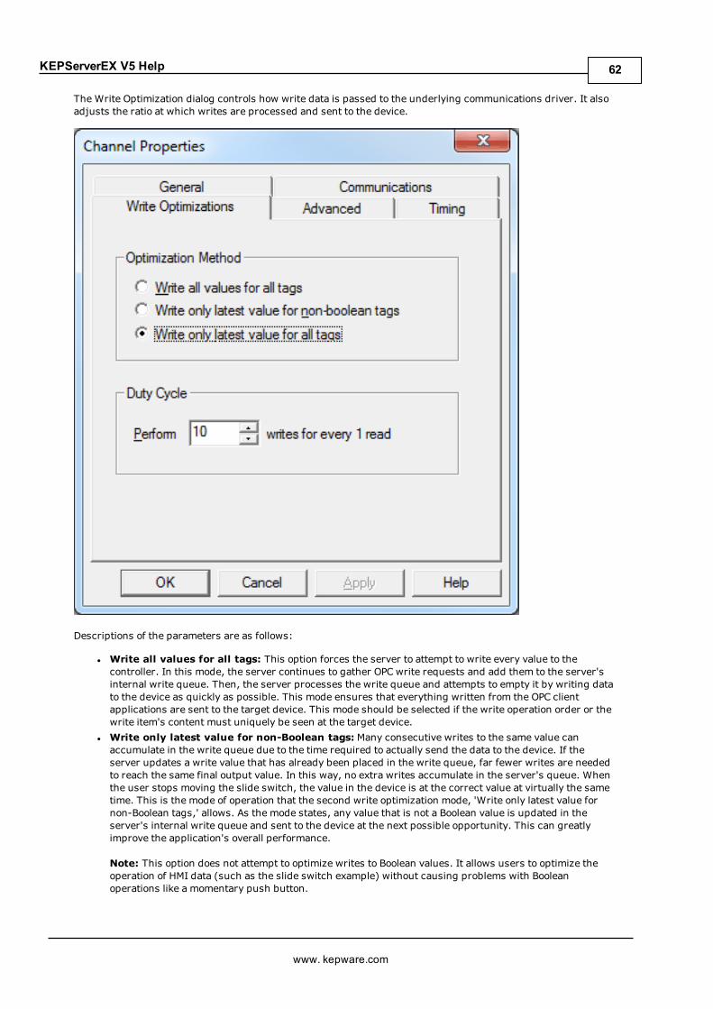
KEPServerEX V5 Help
The Write Optimization dialog controls how write data is passed to the underlying communications driver. It alsoadjusts the ratio at which writes are processed and sent to the device.
Descriptions of the parameters are as follows:
l Write all values for all tags: This option forces the server to attempt to write every value to thecontroller. In this mode, the server continues to gather OPC write requests and add them to the server'sinternal write queue. Then, the server processes the write queue and attempts to empty it by writing datato the device as quickly as possible. This mode ensures that everything written from the OPC clientapplications are sent to the target device. This mode should be selected if the write operation order or thewrite item's content must uniquely be seen at the target device.
l Write only latest value for non-Boolean tags: Many consecutive writes to the same value canaccumulate in the write queue due to the time required to actually send the data to the device. If theserver updates a write value that has already been placed in the write queue, far fewer writes are neededto reach the same final output value. In this way, no extra writes accumulate in the server's queue. Whenthe user stops moving the slide switch, the value in the device is at the correct value at virtually the sametime. This is the mode of operation that the second write optimization mode, 'Write only latest value fornon-Boolean tags,' allows. As the mode states, any value that is not a Boolean value is updated in theserver's internal write queue and sent to the device at the next possible opportunity. This can greatlyimprove the application's overall performance.
Note: This option does not attempt to optimize writes to Boolean values. It allows users to optimize theoperation of HMI data (such as the slide switch example) without causing problems with Booleanoperations like a momentary push button.
www. kepware.com
62

KEPServerEX V5 Help
l Write only the latest value for all tags: This option takes the theory behind the second optimizationmode and applies it to all tags. It is especially useful if the application only needs to send the latest valueto the device. This mode optimizes all writes by updating the tags currently in the write queue before theyare sent. This is the default mode.
Duty CycleThe Duty Cycle selection is used to control the ratio of write operations to read operations. The ratio is alwaysbased on one read for every one to ten writes. The duty cycle is set to ten by default, meaning that ten writesoccur for each read operation. Although the application is doing a large number of continuous writes, it must beensured that read data is still given time to process. A setting of one results in one read operation for every writeoperation. If there are no write operations to perform, reads are processed continuously.
Note: It is recommended that the application be characterized for compatibility with the write optimizationenhancements before being used in a production environment.
Channel Properties - Device DiscoveryThe Device Discovery tab is available for drivers that support device discovery, and is used to specify parametersfor locating devices on the network. Once devices are found, they may be added to the channel. The maximumnumber of devices that can be discovered at once is 65535.
Descriptions of the parameters are as follows:
l Name: This parameter specifies the name of the discovered device.l ID: This parameter specifies the ID of the discovered device. This may be the device ID or the device's IPaddress, depending on the driver being used.
l Description: This parameter specifies the description of the discovered device.l Begin discovery...: This button launches the Discovery Settings dialog, which is used to specify thediscovery parameters. Its parameters and appearance are driver-specific.
l Add selected device...: This button launches the General tab in the driver's Device Properties.
Note: For more information on device discovery, refer to the driver's help documentation.
www. kepware.com
63
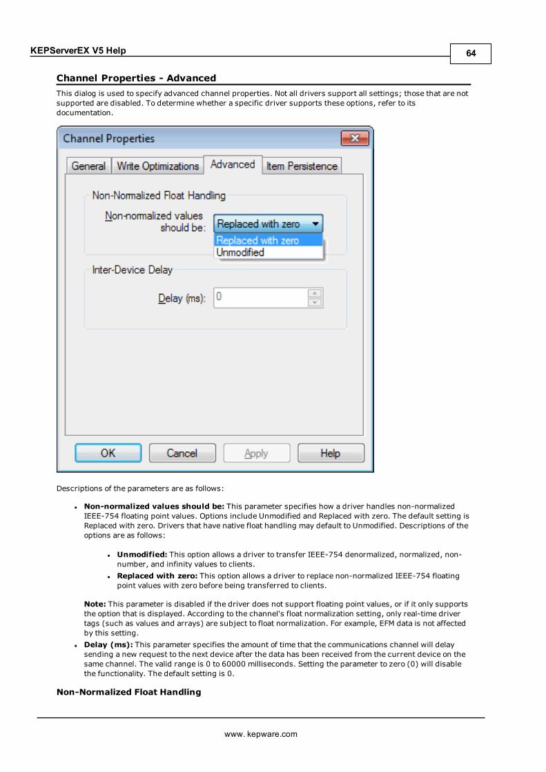
KEPServerEX V5 Help
Channel Properties - AdvancedThis dialog is used to specify advanced channel properties. Not all drivers support all settings; those that are notsupported are disabled. To determine whether a specific driver supports these options, refer to itsdocumentation.
Descriptions of the parameters are as follows:
l Non-normalized values should be: This parameter specifies how a driver handles non-normalizedIEEE-754 floating point values. Options include Unmodified and Replaced with zero. The default setting isReplaced with zero. Drivers that have native float handling may default to Unmodified. Descriptions of theoptions are as follows:
l Unmodified: This option allows a driver to transfer IEEE-754 denormalized, normalized, non-number, and infinity values to clients.
l Replaced with zero: This option allows a driver to replace non-normalized IEEE-754 floatingpoint values with zero before being transferred to clients.
Note: This parameter is disabled if the driver does not support floating point values, or if it only supportsthe option that is displayed. According to the channel's float normalization setting, only real-time drivertags (such as values and arrays) are subject to float normalization. For example, EFM data is not affectedby this setting.
l Delay (ms): This parameter specifies the amount of time that the communications channel will delaysending a new request to the next device after the data has been received from the current device on thesame channel. The valid range is 0 to 60000 milliseconds. Setting the parameter to zero (0) will disablethe functionality. The default setting is 0.
Non-Normalized Float Handling
www. kepware.com
64
KEPServerEX V5 Help
Non-normalized float handling allows users to specify how a driver handles non-normalized floating point data. Anon-normalized value is defined as Infinity, Not-a-Number (NaN), or as a Denormalized Number. For moreinformation on the floating point values, refer toHow To ... Work with Non-Normalized Floating PointValues.
What is a Device?Devices represent the PLCs or other hardware with which the server communicates. The device driver that thechannel is using restricts device selection.
Adding a DeviceDevices can be added using the New Device Wizard both at the initial setup and afterward. To do so, click Edit |New Device. Users will be prompted to enter the device name, which is user-defined and should be logical forthe device. This will be the browser branch name used in OPC links to access the device's assigned tags. Forinformation on reserved characters, refer toHow To... Properly Name a Channel, Device, Tag, and TagGroup.
Users will also be prompted to enter a Network ID, which is a number or string that uniquely identifies the deviceon the device's network. Networked, multi-dropped devices must have a unique identifier so that the server'sdata requests are routed correctly. Devices that are not multi-dropped do not need an ID; this setting is notavailable.
Removing a DeviceTo remove a device from the project, select the desired device then press Delete. Alternatively, click Edit |Delete.
Displaying Device PropertiesTo display a device's properties, first select the device and then click Edit | Properties. For more information,refer toDevice Properties.
Device Properties - GeneralA device represents a single target on a communications channel. If the driver supports multiple controllers,users must enter a device ID for each controller. The following images display the appearance of the General tabin the device properties of serial and Ethernet devices.
Serial Device Properties
www. kepware.com
65

KEPServerEX V5 Help
Ethernet Device Properties
www. kepware.com
66
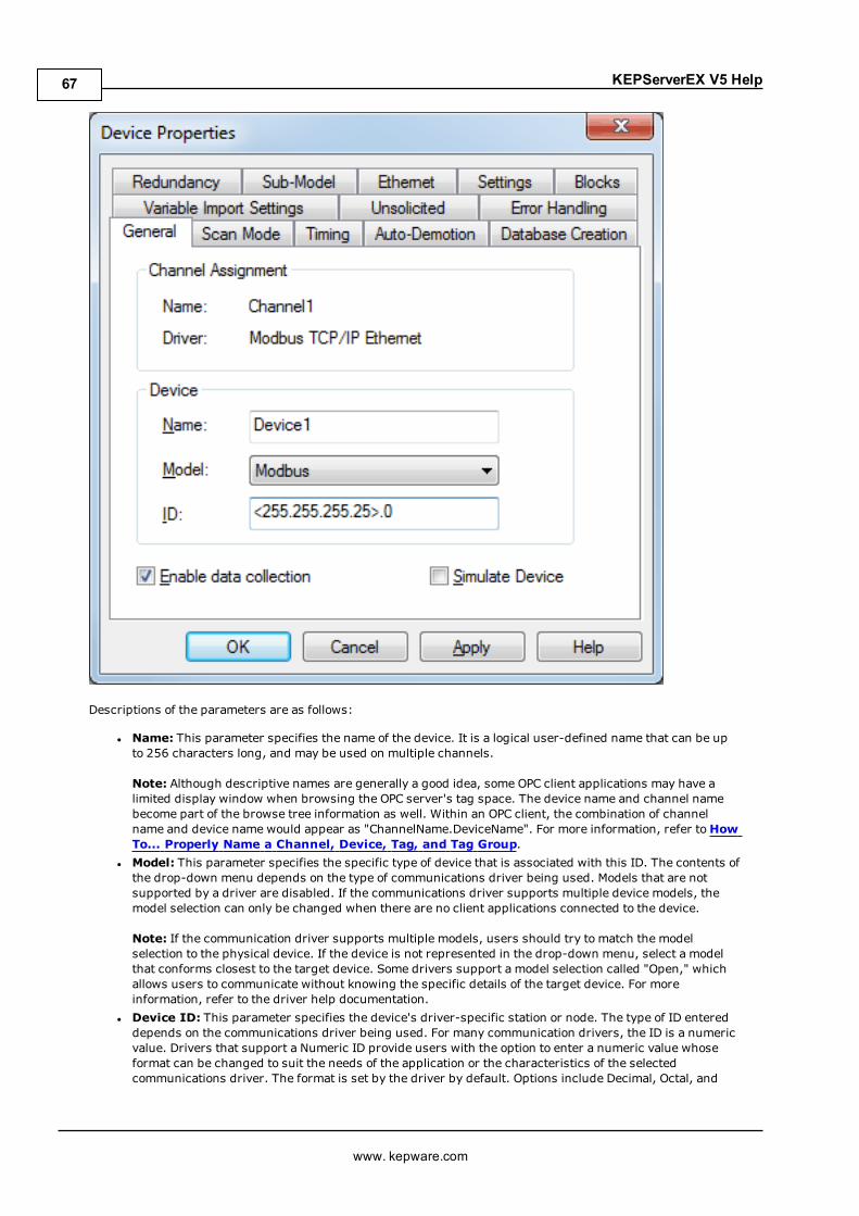
KEPServerEX V5 Help
Descriptions of the parameters are as follows:
l Name: This parameter specifies the name of the device. It is a logical user-defined name that can be upto 256 characters long, and may be used on multiple channels.
Note: Although descriptive names are generally a good idea, some OPC client applications may have alimited display window when browsing the OPC server's tag space. The device name and channel namebecome part of the browse tree information as well. Within an OPC client, the combination of channelname and device name would appear as "ChannelName.DeviceName". For more information, refer toHowTo... Properly Name a Channel, Device, Tag, and Tag Group.
l Model: This parameter specifies the specific type of device that is associated with this ID. The contents ofthe drop-down menu depends on the type of communications driver being used. Models that are notsupported by a driver are disabled. If the communications driver supports multiple device models, themodel selection can only be changed when there are no client applications connected to the device.
Note: If the communication driver supports multiple models, users should try to match the modelselection to the physical device. If the device is not represented in the drop-down menu, select a modelthat conforms closest to the target device. Some drivers support a model selection called "Open," whichallows users to communicate without knowing the specific details of the target device. For moreinformation, refer to the driver help documentation.
l Device ID: This parameter specifies the device's driver-specific station or node. The type of ID entereddepends on the communications driver being used. For many communication drivers, the ID is a numericvalue. Drivers that support a Numeric ID provide users with the option to enter a numeric value whoseformat can be changed to suit the needs of the application or the characteristics of the selectedcommunications driver. The format is set by the driver by default. Options include Decimal, Octal, and
www. kepware.com
67
KEPServerEX V5 Help
Hexadecimal.
Note: If the driver is Ethernet-based or supports an unconventional station or node name, the device'sTCP/IP address may be used as the device ID. TCP/IP addresses consist of four values that are separatedby periods, with each value in the range of 0 to 255. Some device IDs are string based. There may beadditional parameters to configure within the ID field, depending on the driver. For more information,refer to the driver's help documentation.
l Enable Data Collection: This parameter controls the device's active state. Although devicecommunications are enabled by default, this parameter can be used to disable a physical device forservicing. Communications are not attempted once a device has been disabled. From a client standpoint,the data is marked as invalid and write operations are not accepted. This parameter can be changed atany time through the menu selection or the device's System tags.
l Simulate Device:When checked, this option places the device into Simulation Mode. In this mode, thedriver does not attempt to communicate with the physical device, but the server continues to return validOPC data. Unlike the Enable data collection parameter, Simulate Device stops physical communicationswith the device, but allows OPC data to be returned to the OPC client as valid data. While in SimulationMode, the server treats all device data as reflective: whatever is written to the simulated device is readback and each OPC item is treated individually. The item's memory map is based on the group UpdateRate. The data is not saved if the server removes the item (such as when the server is reinitialized). Thedefault setting is unchecked.
Note: This mode's System tag ("_Simulated") is read only and cannot be written to for Runtimeprotection. The System tag allows this parameter to be monitored from the client.
Caution: Simulation Mode is for test and simulation purposes only. It should never be applied or used ina production environment.
Note: In Simulation mode, the item's memory map is based on client update rate(s)(Group Update Ratefor OPC clients or Scan Rate for native and DDE interfaces). This means that two clients that reference thesame item with different update rates return different data.See the Simulation Mode Example
Note:With the server's online full-time operation, these parameters can be changed at any time. Changing thedevice name can prevent clients from registering data with the server. If a client has already acquired items fromthe server before the name was changed, the items are unaffected. If the client application releases the item afterthe device name has changed and attempts to reacquire it using the old name, the item is not accepted. Usersshouldn't make changes to parameters like device name, after a large client application has developed. Utilize theUser Manager to restrict access rights to server features to prevent operators from changing parameters.
test1test
Device Properties - Scan ModeThe Scan Mode parameters specify the device's scan rate. Options include Respect client specified scan rate,Request data no faster than x, Request all data at x, and Do not scan, demand poll only. The default setting isRespect client specified scan rate.
1test1
www. kepware.com
68
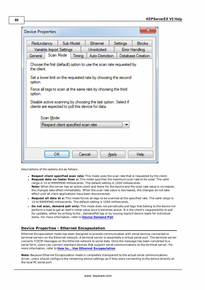
KEPServerEX V5 Help
Descriptions of the options are as follows:
l Respect client specified scan rate: This mode uses the scan rate that is requested by the client.l Request data no faster than x: This mode specifies the maximum scan rate to be used. The validrange is 10 to 99999990 milliseconds. The default setting is 1000 milliseconds.Note: When the server has an active client and items for the device and the scan rate value is increased,the changes take effect immediately. When the scan rate value is decreased, the changes do not takeeffect until all client applications have been disconnected.
l Request all data at x: This mode forces all tags to be scanned at the specified rate. The valid range is10 to 99999990 milliseconds. The default setting is 1000 milliseconds.
l Do not scan, demand poll only: This mode does not periodically poll tags that belong to the device norperform a read to get an item's initial value once it becomes active. It is the client's responsibility to pollfor updates, either by writing to the _DemandPoll tag or by issuing explicit device reads for individualitems. For more information, refer toDevice Demand Poll.
Device Properties - Ethernet EncapsulationEthernet Encapsulation mode has been designed to provide communication with serial devices connected toterminal servers on the Ethernet network. A terminal server is essentially a virtual serial port. The terminal serverconverts TCP/IP messages on the Ethernet network to serial data. Once the message has been converted to aserial form, users can connect standard devices that support serial communications to the terminal server. Formore information, refer toHow to... Use Ethernet Encapsulation.
Note: Because Ethernet Encapsulation mode is completely transparent to the actual serial communicationsdriver, users should configure the remaining device settings as if they were connecting to the device directly onthe local PC serial port.
www. kepware.com
69
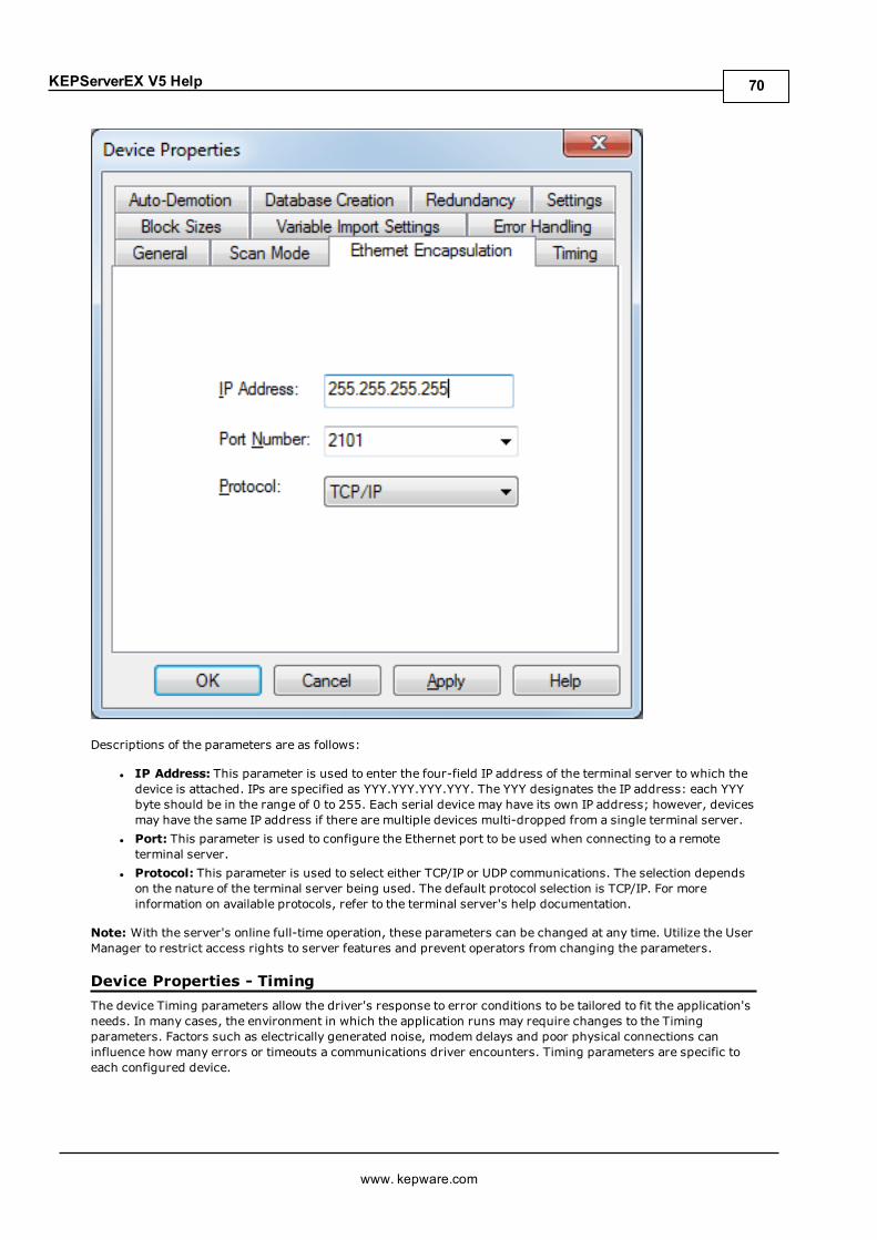
KEPServerEX V5 Help
Descriptions of the parameters are as follows:
l IP Address: This parameter is used to enter the four-field IP address of the terminal server to which thedevice is attached. IPs are specified as YYY.YYY.YYY.YYY. The YYY designates the IP address: each YYYbyte should be in the range of 0 to 255. Each serial device may have its own IP address; however, devicesmay have the same IP address if there are multiple devices multi-dropped from a single terminal server.
l Port: This parameter is used to configure the Ethernet port to be used when connecting to a remoteterminal server.
l Protocol: This parameter is used to select either TCP/IP or UDP communications. The selection dependson the nature of the terminal server being used. The default protocol selection is TCP/IP. For moreinformation on available protocols, refer to the terminal server's help documentation.
Note: With the server's online full-time operation, these parameters can be changed at any time. Utilize the UserManager to restrict access rights to server features and prevent operators from changing the parameters.
Device Properties - TimingThe device Timing parameters allow the driver's response to error conditions to be tailored to fit the application'sneeds. In many cases, the environment in which the application runs may require changes to the Timingparameters. Factors such as electrically generated noise, modem delays and poor physical connections caninfluence how many errors or timeouts a communications driver encounters. Timing parameters are specific toeach configured device.
www. kepware.com
70
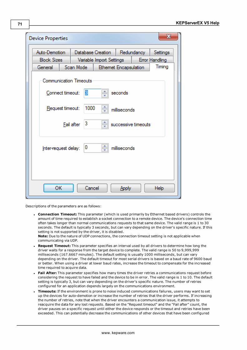
KEPServerEX V5 Help
Descriptions of the parameters are as follows:
l Connection Timeout: This parameter (which is used primarily by Ethernet based drivers) controls theamount of time required to establish a socket connection to a remote device. The device's connection timeoften takes longer than normal communications requests to that same device. The valid range is 1 to 30seconds. The default is typically 3 seconds, but can vary depending on the driver's specific nature. If thissetting is not supported by the driver, it is disabled.Note: Due to the nature of UDP connections, the connection timeout setting is not applicable whencommunicating via UDP.
l Request Timeout: This parameter specifies an interval used by all drivers to determine how long thedriver waits for a response from the target device to complete. The valid range is 50 to 9,999,999milliseconds (167.6667 minutes). The default setting is usually 1000 milliseconds, but can varydepending on the driver. The default timeout for most serial drivers is based on a baud rate of 9600 baudor better. When using a driver at lower baud rates, increase the timeout to compensate for the increasedtime required to acquire data.
l Fail After: This parameter specifies how many times the driver retries a communications request beforeconsidering the request to have failed and the device to be in error. The valid range is 1 to 10. The defaultsetting is typically 3, but can vary depending on the driver's specific nature. The number of retriesconfigured for an application depends largely on the communications environment.
l Timeouts: If the environment is prone to noise induced communications failures, users may want to setup the devices for auto-demotion or increase the number of retries that the driver performs. If increasingthe number of retries, note that when the driver encounters a communication issue, it attempts toreacquire the data for any lost requests. Based on the "Request timeout" and the "Fail after" count, thedriver pauses on a specific request until either the device responds or the timeout and retries have beenexceeded. This can potentially decrease the communications of other devices that have been configured
www. kepware.com
71

KEPServerEX V5 Help
on that channel. In this situation, it may be more appropriate to utilize the auto-demotion functionality tooptimize communications with other devices on the same channel.
l Inter-Request Delay: This parameter specifies how long the driver waits before sending the nextrequest to the target device. It overrides the normal polling frequency of tags associated with the device,as well as one-shot reads and writes. This delay can be useful when dealing with devices with slowturnaround times and in cases where network load is a concern. Configuring a delay for a device affectscommunications with all other devices on the channel. It is recommended that users segregate any devicethat requires an inter-request delay to a separate channel if possible. Other communications settings(such as Communication Serialization) can extend this delay. The valid range is 0 to 300,000milliseconds; however, some drivers may limit the maximum value due to a function of their particulardesign. The default setting is 0, which indicates no delay between requests with the target device. Thissetting is disabled if it is not supported by the driver.
Notes:
1. To determine when communication errors are occurring, use the device's _Error system tag.
2. To determine how long the device has been in an error state, use the _SecondsInError tag located in thedevice's _System tag group.
3. With the server's online full-time operation, these parameters can be changed at any time. Utilize theUser Manager to restrict access rights to server features to prevent operators from changing theparameters.
Device Properties - Auto-DemotionThe Auto-Demotion parameters allow a driver to temporarily place a device off-scan in the event that a device isnot responding. By placing a non-responsive device offline for a specific time period, the driver can continue tooptimize its communications with other devices on the same channel. After the time period has been reached, thedriver re-attempts to communicate with the non-responsive device. If the device is responsive, the device isplaced on-scan; otherwise, it restarts its off-scan time period.
www. kepware.com
72

KEPServerEX V5 Help
Descriptions of the parameters are as follows:
l Enable auto device demotion on communication failures:When checked, auto demotion isenabled.
l Demote after __ successive failures: This parameter indicates how many successive cycles ofrequest timeouts and retries occur before the device is placed off-scan. The valid range is 1 to 30successive failures. The default setting is 3.
l Demote for __milliseconds: This parameter indicates how long the device should be placed off-scanwhen the "Demote after" parameter has been reached. During this period, no read requests are sent tothe device and all data associated with the read requests are set to bad quality. When this period expires,the driver places the device on-scan and allows for another attempt at communications. The valid range is100 to 3600000 milliseconds. The default setting is 10000 milliseconds.
l Discard write requests during the demotion period: This parameter controls whether or not writerequests should be attempted during the off-scan period. The default setting always sends writerequests regardless of the demotion period. If users choose to discard writes, the server automaticallyfails any write request received from a client and does not post an "Unable to write..." message to theserver Event Log.
Note: Users can determine when a device is off-scan by monitoring its demoted state by using the _AutoDemoted System tag.
Device Properties - Time SynchronizationThis dialog is used to specify the device's time zone and time synchronization settings. It primarily applies toEFM data, which is time stamped. Because EFM devices are usually battery-powered at remote locations, the
www. kepware.com
73
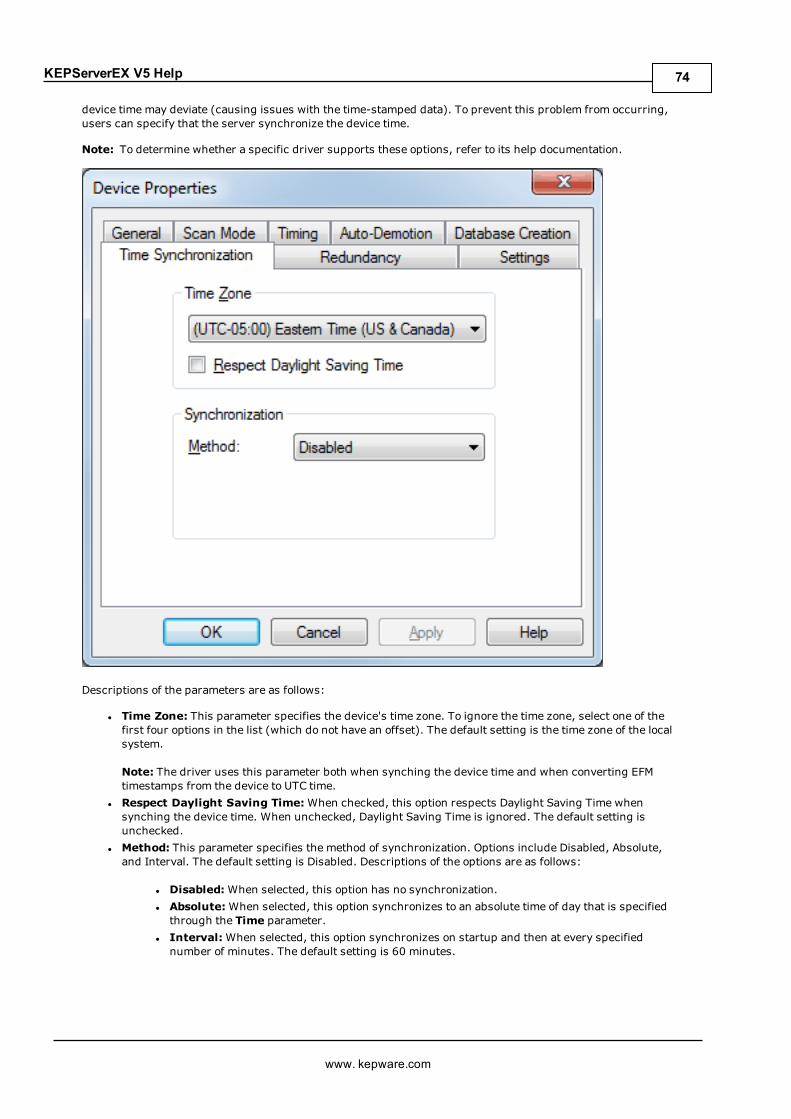
KEPServerEX V5 Help
device time may deviate (causing issues with the time-stamped data). To prevent this problem from occurring,users can specify that the server synchronize the device time.
Note: To determine whether a specific driver supports these options, refer to its help documentation.
Descriptions of the parameters are as follows:
l Time Zone: This parameter specifies the device's time zone. To ignore the time zone, select one of thefirst four options in the list (which do not have an offset). The default setting is the time zone of the localsystem.
Note: The driver uses this parameter both when synching the device time and when converting EFMtimestamps from the device to UTC time.
l Respect Daylight Saving Time:When checked, this option respects Daylight Saving Time whensynching the device time. When unchecked, Daylight Saving Time is ignored. The default setting isunchecked.
l Method: This parameter specifies the method of synchronization. Options include Disabled, Absolute,and Interval. The default setting is Disabled. Descriptions of the options are as follows:
l Disabled:When selected, this option has no synchronization.l Absolute:When selected, this option synchronizes to an absolute time of day that is specifiedthrough the Time parameter.
l Interval:When selected, this option synchronizes on startup and then at every specifiednumber of minutes. The default setting is 60 minutes.
www. kepware.com
74
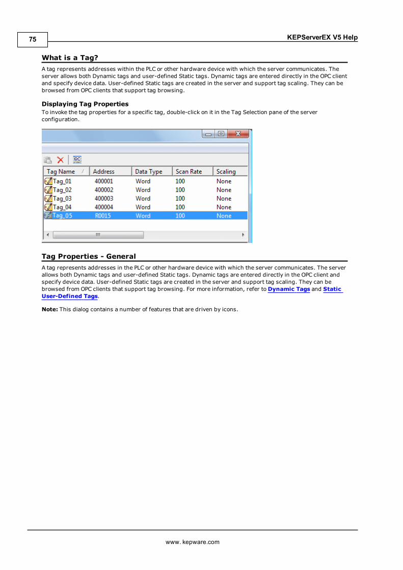
KEPServerEX V5 Help
What is a Tag?A tag represents addresses within the PLC or other hardware device with which the server communicates. Theserver allows both Dynamic tags and user-defined Static tags. Dynamic tags are entered directly in the OPC clientand specify device data. User-defined Static tags are created in the server and support tag scaling. They can bebrowsed from OPC clients that support tag browsing.
Displaying Tag PropertiesTo invoke the tag properties for a specific tag, double-click on it in the Tag Selection pane of the serverconfiguration.
Tag Properties - GeneralA tag represents addresses in the PLC or other hardware device with which the server communicates. The serverallows both Dynamic tags and user-defined Static tags. Dynamic tags are entered directly in the OPC client andspecify device data. User-defined Static tags are created in the server and support tag scaling. They can bebrowsed from OPC clients that support tag browsing. For more information, refer toDynamic Tags and StaticUser-Defined Tags.
Note: This dialog contains a number of features that are driven by icons.
www. kepware.com
75
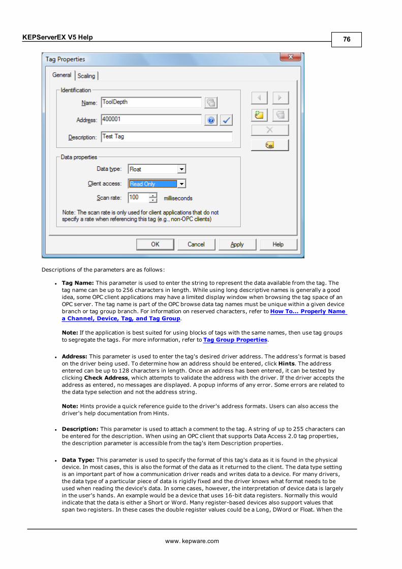
KEPServerEX V5 Help
Descriptions of the parameters are as follows:
l Tag Name: This parameter is used to enter the string to represent the data available from the tag. Thetag name can be up to 256 characters in length. While using long descriptive names is generally a goodidea, some OPC client applications may have a limited display window when browsing the tag space of anOPC server. The tag name is part of the OPC browse data tag names must be unique within a given devicebranch or tag group branch. For information on reserved characters, refer toHow To... Properly Namea Channel, Device, Tag, and Tag Group.
Note: If the application is best suited for using blocks of tags with the same names, then use tag groupsto segregate the tags. For more information, refer to Tag Group Properties.
l Address: This parameter is used to enter the tag's desired driver address. The address's format is basedon the driver being used. To determine how an address should be entered, click Hints. The addressentered can be up to 128 characters in length. Once an address has been entered, it can be tested byclicking Check Address, which attempts to validate the address with the driver. If the driver accepts theaddress as entered, no messages are displayed. A popup informs of any error. Some errors are related tothe data type selection and not the address string.
Note: Hints provide a quick reference guide to the driver's address formats. Users can also access thedriver's help documentation from Hints.
l Description: This parameter is used to attach a comment to the tag. A string of up to 255 characters canbe entered for the description. When using an OPC client that supports Data Access 2.0 tag properties,the description parameter is accessible from the tag's item Description properties.
l Data Type: This parameter is used to specify the format of this tag's data as it is found in the physicaldevice. In most cases, this is also the format of the data as it returned to the client. The data type settingis an important part of how a communication driver reads and writes data to a device. For many drivers,the data type of a particular piece of data is rigidly fixed and the driver knows what format needs to beused when reading the device's data. In some cases, however, the interpretation of device data is largelyin the user's hands. An example would be a device that uses 16-bit data registers. Normally this wouldindicate that the data is either a Short or Word. Many register-based devices also support values thatspan two registers. In these cases the double register values could be a Long, DWord or Float. When the
www. kepware.com
76

KEPServerEX V5 Help
driver being used supports this level of flexibility, users must tell it how to read data for this tag. Byselecting the appropriate data type, the driver is being told to read one, two, four, eight, or sixteenregisters or possibly a Boolean value. The driver governs the data format being chosen. For specificinformation on available data types, click Hints to access the driver's help documentation. Available datatype selections are as follows:
Default - This selection allows the driver to choose its default data type. Boolean - Binary value of true or false Char - Signed 8-bit integer data Byte - Unsigned 8-bit integer data Short - Signed 16-bit integer data Word - Unsigned 16-bit integer data Long - Signed 32-bit integer data DWord - Unsigned 32-bit integer data LLong - Signed 64-bit integer data QWord - Unsigned 64-bit integer data Float - 32-bit real value IEEE-754 standard definition Double - 64-bit real value IEEE-754 standard definition String - Null-terminated Unicode string BCD - Two byte-packed BCD value range is 0-9999 LBCD - Four byte-packed BCD value range is 0-99999999 Date - SeeMicrosoft® Knowledge Base.
l Client Access: This parameter is used to specify whether the tag is Read Only or Read/Write. Byselecting Read Only, users can prevent client applications from changing the data contained in this tag.By selecting Read/Write, users allow client applications to change this tag's value as needed. The Clientaccess selection also affects how the tag appears in the browse space of an OPC client. Many OPC clientapplications allow users to filter tags based on their attributes. Changing the access method of this tagmay change how and when the tag appears in the browse space of the OPC client.
l Scan Rate: This parameter is used to specify the update interval for this tag when used with a non-OPCclient. OPC clients can control the rate at which data is scanned by using the update rate that is part of allOPC groups. Normally non-OPC clients don't have that luxury. The server is used to specify an update rateon a tag per tag basis for non-OPC clients. Using the scan rate, users can tailor the bandwidthrequirements of the server to suit the needs of the application. If, for example, data that changes veryslowly needs to be read, there is no reason to read the value very often. Using the scan rate this tag canbe forced to read at a slower rate reducing the demand on the communications channel. The valid rangeis 10 to 99999990 milliseconds (ms), with a 10 ms increment. The default is 100 milliseconds.
Note:With the server's online full-time operation, these parameters can be changed at any time. Changes madeto tag properties take effect immediately; however, OPC clients that have already connected to this tag are notaffected until they release and attempt to reacquire it. Utilize the User Manager to restrict access rights to serverfeatures and prevent operators from changing the parameters.
www. kepware.com
77
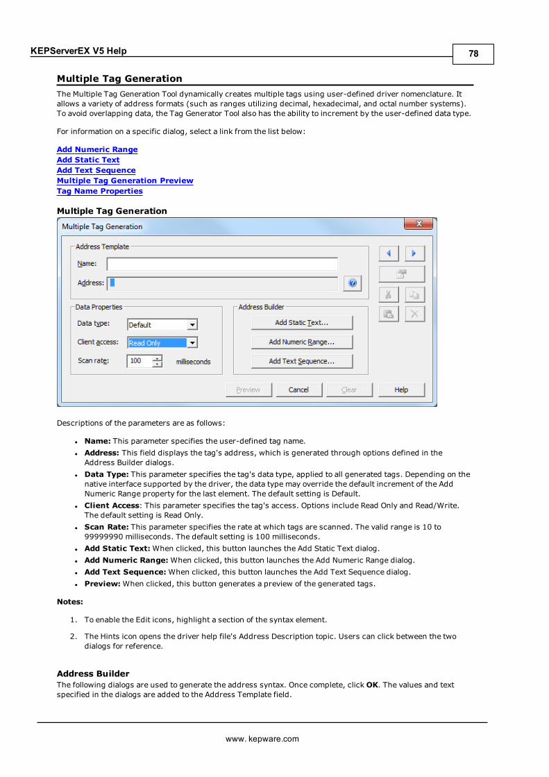
KEPServerEX V5 Help
Multiple Tag GenerationThe Multiple Tag Generation Tool dynamically creates multiple tags using user-defined driver nomenclature. Itallows a variety of address formats (such as ranges utilizing decimal, hexadecimal, and octal number systems).To avoid overlapping data, the Tag Generator Tool also has the ability to increment by the user-defined data type.
For information on a specific dialog, select a link from the list below:
Add Numeric RangeAdd Static TextAdd Text SequenceMultiple Tag Generation PreviewTag Name Properties
Multiple Tag Generation
Descriptions of the parameters are as follows:
l Name: This parameter specifies the user-defined tag name.l Address: This field displays the tag's address, which is generated through options defined in theAddress Builder dialogs.
l Data Type: This parameter specifies the tag's data type, applied to all generated tags. Depending on thenative interface supported by the driver, the data type may override the default increment of the AddNumeric Range property for the last element. The default setting is Default.
l Client Access: This parameter specifies the tag's access. Options include Read Only and Read/Write.The default setting is Read Only.
l Scan Rate: This parameter specifies the rate at which tags are scanned. The valid range is 10 to99999990 milliseconds. The default setting is 100 milliseconds.
l Add Static Text:When clicked, this button launches the Add Static Text dialog.l Add Numeric Range:When clicked, this button launches the Add Numeric Range dialog.l Add Text Sequence:When clicked, this button launches the Add Text Sequence dialog.l Preview:When clicked, this button generates a preview of the generated tags.
Notes:
1. To enable the Edit icons, highlight a section of the syntax element.
2. The Hints icon opens the driver help file's Address Description topic. Users can click between the twodialogs for reference.
Address BuilderThe following dialogs are used to generate the address syntax. Once complete, clickOK. The values and textspecified in the dialogs are added to the Address Template field.
www. kepware.com
78
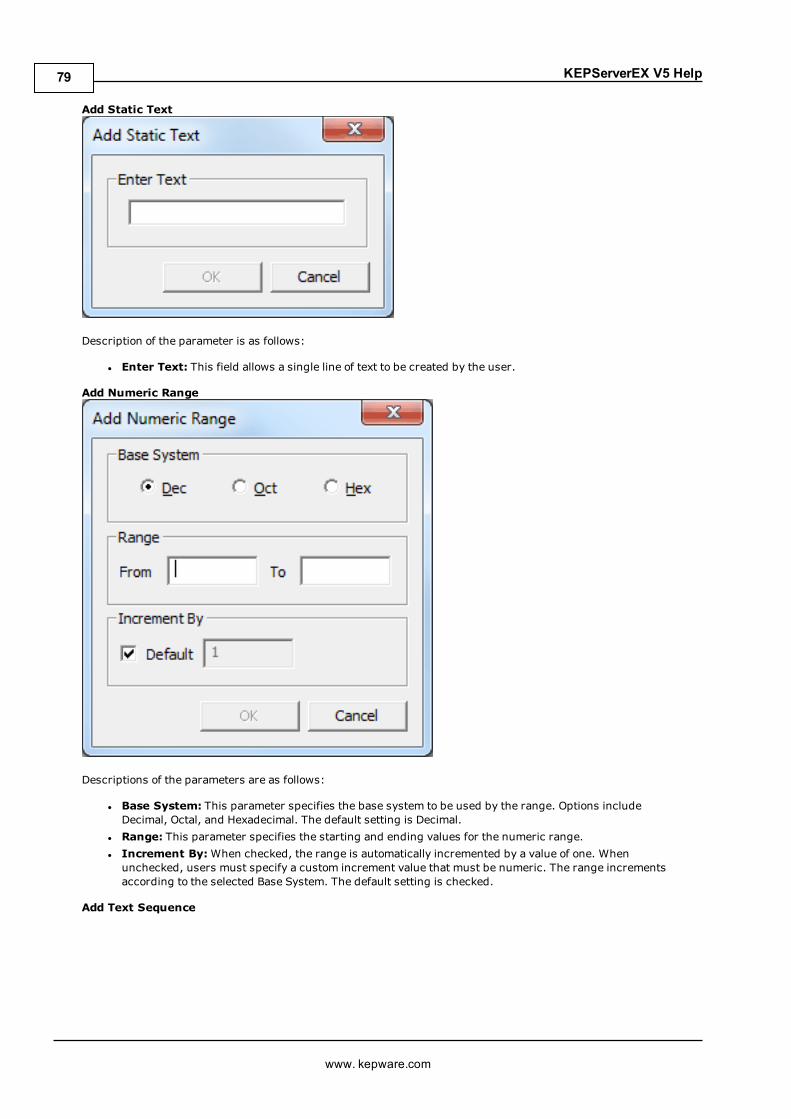
KEPServerEX V5 Help
Add Static Text
Description of the parameter is as follows:
l Enter Text: This field allows a single line of text to be created by the user.
Add Numeric Range
Descriptions of the parameters are as follows:
l Base System: This parameter specifies the base system to be used by the range. Options includeDecimal, Octal, and Hexadecimal. The default setting is Decimal.
l Range: This parameter specifies the starting and ending values for the numeric range.l Increment By:When checked, the range is automatically incremented by a value of one. Whenunchecked, users must specify a custom increment value that must be numeric. The range incrementsaccording to the selected Base System. The default setting is checked.
Add Text Sequence
www. kepware.com
79

KEPServerEX V5 Help
Description of the parameter is as follows:
l Enter Text: This field allows multiple strings to be created by the user. Each string is insertedindependently of the other strings specified in the list.
Multiple Tag Generation Preview
www. kepware.com
80
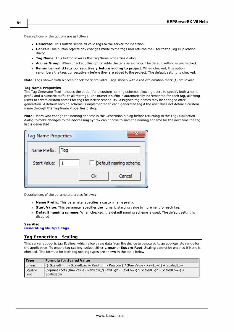
KEPServerEX V5 Help
Descriptions of the options are as follows:
l Generate: This button sends all valid tags to the server for insertion.l Cancel: This button rejects any changes made to the tags and returns the user to the Tag Duplicationdialog.
l Tag Name: This button invokes the Tag Name Properties dialog.l Add as Group: When checked, this option adds the tags as a group. The default setting is unchecked.l Renumber valid tags consecutively before adding to project:When checked, this optionrenumbers the tags consecutively before they are added to the project. The default setting is checked.
Note: Tags shown with a green check mark are valid. Tags shown with a red exclamation mark (!) are invalid.
Tag Name PropertiesThe Tag Generator Tool includes the option for a custom naming scheme, allowing users to specify both a nameprefix and a numeric suffix to all the tags. The numeric suffix is automatically incremented for each tag, allowingusers to create custom names for tags for better readability. Assigned tag names may be changed aftergeneration. A default naming scheme is implemented to each generated tag if the user does not define a customname through the Tag Name Properties dialog.
Note: Users who change the naming scheme in the Generation dialog before returning to the Tag Duplicationdialog to make changes to the addressing syntax can choose to save the naming scheme for the next time the taglist is generated.
Descriptions of the parameters are as follows:
l Name Prefix: This parameter specifies a custom name prefix.l Start Value: This parameter specifies the numeric starting value to increment for each tag.l Default naming scheme:When checked, the default naming scheme is used. The default setting isdisabled.
See Also:Generating Multiple Tags
Tag Properties - ScalingThis server supports tag Scaling, which allows raw data from the device to be scaled to an appropriate range forthe application. To enable tag scaling, select either Linear or Square Root. Scaling cannot be enabled if None ischecked. The formula for both tag scaling types are shown in the table below.
Type Formula for Scaled ValueLinear (((ScaledHigh - ScaledLow)/(RawHigh - RawLow))*(RawValue - RawLow)) + ScaledLowSquareroot
(Square root ((RawValue - RawLow)/(RawHigh - RawLow))*(ScaledHigh - ScaledLow)) +ScaledLow
www. kepware.com
81

KEPServerEX V5 Help
Descriptions of the parameters are as follows:
l Raw Value Range: These settings are used to specify the range of raw data from the device. The rawvalue High setting must be greater than the Low setting. The valid range depends on the raw tag value'sdata type. For example, if the raw value is Short, the valid range of the raw value would be from -32768 to32767.
l Scaled Value Range: These settings are used to specify the range of the resulting scaled value.l Data Type: A scaled value is usually assumed to result in a floating-point value, although the server doesnot make that assumption. The data type can be set to any valid OPC data type. This gives users the abilityto scale from a raw data type such as Short to an engineering value with a data type of Long if needed.The default scaled data type is Double.
l High and Low: The scaled value High must be greater than the scaled value Low. The valid rangedepends on the data type of the scaled value. For example, if the scaled data type is set to Long, then thevalid range would be -2147483648 to 2147483647.
l Clamp: The raw data from the device may exceed the range that has been specified for the raw data.When this occurs, the scaled value is also forced outside of the established range. To prevent this fromoccurring, the High and Low Clamps can be used to constrain the scaled value to the range specified.
l Units: The server also allows a unit's string to be assigned to a scaled tag. The unit's string can be up to32 characters long.
l Negate scaled value: This parameter forces the resulting value to be negated before being passed tothe client.
Note: The OPC server supports the OPC tag properties available in the 2.0 Data Access specifications. If the OPCclient being used supports these properties, it can automatically configure the range of objects (such as userinput objects or displays) by using the Scaling settings. Utilize the User Manager to restrict access rights toserver features to prevent any unauthorized operator from changing these parameters.
Dynamic TagsDynamic tag addressing is a second method of defining tags that allows users to define tags only in the clientapplication. As such, instead of creating a tag item in the client that addresses another tag item created in theserver, users only need to create tag items in the client that directly accesses the device driver's addresses. Onclient connect, the server creates a virtual tag for that location and starts scanning for data automatically.
To specify an optional data type, append one of the following strings after the '@' symbol:
www. kepware.com
82

KEPServerEX V5 Help
l BCDl Booleanl Bytel Charl Doublel DWordl Floatl LBCDl LLongl Longl QWordl Shortl Stringl Word
If the data type is omitted, the driver chooses a default data type based on the device and address beingreferenced. The default data types for all locations are documented in each individual driver's helpdocumentation. If the data type specified is not valid for the device location, the server rejects the tag and anerror posts in the Event Log.
OPC Client Using Dynamic Addressing ExampleScan the 16-bit location "R0001" on the Simulator device. The following Dynamic tag examples assume that theproject created is part of the example.
1. Start the OPC client application and connect to the server.
2. Using the Simulator Driver, create a channel and name it "Channel1." Then, make a device and name it"Device1."
3. In the client application, define an item name as "Channel1.Device1.R0001@Short."
4. The client project automatically starts receiving data. The default data type for address R0001 in theSimulator device is Word. To override this, the @Short has been appended to select a data type of Short.
Note: When utilizing Dynamic tags in an OPC client application, the use of the @[Data Type] modifier is notnormally required. OPC clients can specify the desired data type as part of the request when registering a link fora specific data item. The data type specified by the OPC client is used if it is supported by the communicationsdriver. The @[Data Type] modifier can be useful when ensuring that a communications driver interprets a pieceof data exactly as needed.
Non-OPC Client ExampleNon-OPC clients can override the update rate on a per-tag basis by appending @[Update Rate].
For example, appending "<DDE service name>|_ddedata!Device1.R0001@500" overrides just the update rate."<DDE service name>|_ddedata!Device1.R0001@500,Short" overrides both update rate and data type.
Notes:
1. The server creates a special Boolean tag for every device in a project that can be used by a client todetermine whether a device is functioning properly. To use this tag, specify the item in the link as "Error."If the device is communicating properly, the tag's value is zero; otherwise, it is one.
2. If the device address is used as the item of a link such that the address matches the name of a user-defined tag in the server, the link references the address pointed to by the user-defined tag.
3. Static tags must be used to scale data in the server.
See Also:Static Tags (User-Defined)Designing a Project: Adding User-Defined Tags
www. kepware.com
83

KEPServerEX V5 Help
Static Tags (User-Defined)The most common method that uses the server to get data from the device to the client application has tworequirements. Users must first define a set of tags in the server project and then use the assigned tag name asthe item of each link between the client and the server. The primary benefit to using this method is that all user-defined tags are available for browsing within most OPC clients. Before deciding whether or not to create Statictags, ensure that the client can browse or import tags from the server.
Note: User-defined tags support scaling.
What is a Tag Group?This server allows tag groups to be added to the project. Tag groups are used to tailor the layout of OPC data intological groupings that fit the application's needs. Tag groups allow multiple sets of identical tags to be addedunder the same device: this can be convenient when a single device handles a number of similar machinesegments.
Tag Group PropertiesFrom an OPC client standpoint, tag groups allow users to segregate OPC data into smaller tag lists, makingfinding specific tags easier when browsing the server. The following image used the supplied OPC Quick Client tocreate Cell1 and Cell2 tag groups and simplify the OPC client browsing.
To add a new tag group to the project, right-click on either an existing device or tag group branch and selectNew Tag Group from the context menu. Alternatively, click on either an existing device or tag group branch andthen click the New Tag Group icon on the toolbar.
www. kepware.com
84
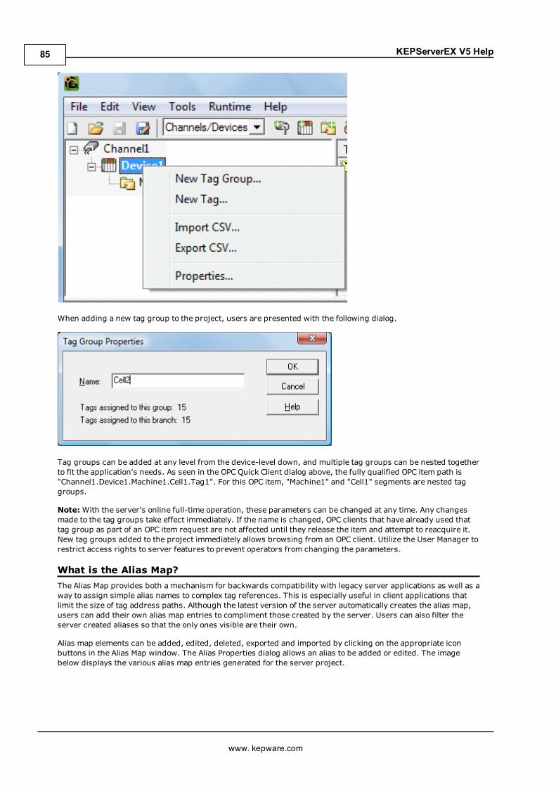
KEPServerEX V5 Help
When adding a new tag group to the project, users are presented with the following dialog.
Tag groups can be added at any level from the device-level down, and multiple tag groups can be nested togetherto fit the application's needs. As seen in the OPC Quick Client dialog above, the fully qualified OPC item path is"Channel1.Device1.Machine1.Cell1.Tag1". For this OPC item, "Machine1" and "Cell1" segments are nested taggroups.
Note:With the server's online full-time operation, these parameters can be changed at any time. Any changesmade to the tag groups take effect immediately. If the name is changed, OPC clients that have already used thattag group as part of an OPC item request are not affected until they release the item and attempt to reacquire it.New tag groups added to the project immediately allows browsing from an OPC client. Utilize the User Manager torestrict access rights to server features to prevent operators from changing the parameters.
What is the Alias Map?The Alias Map provides both a mechanism for backwards compatibility with legacy server applications as well as away to assign simple alias names to complex tag references. This is especially useful in client applications thatlimit the size of tag address paths. Although the latest version of the server automatically creates the alias map,users can add their own alias map entries to compliment those created by the server. Users can also filter theserver created aliases so that the only ones visible are their own.
Alias map elements can be added, edited, deleted, exported and imported by clicking on the appropriate iconbuttons in the Alias Map window. The Alias Properties dialog allows an alias to be added or edited. The imagebelow displays the various alias map entries generated for the server project.
www. kepware.com
85

KEPServerEX V5 Help
Descriptions of the icons are as follows.
l To create a new alias, click .
l To edit an existing alias, select the alias from the list and then click .
l To deletemanually created aliases, click .
l To import an alias map as a .CSV file, click .
l To export an alias map as a .CSV file, click .
Note: When checked, the Show auto-generated aliases parameter shows the server's automaticallygenerated aliases. The default setting is unchecked.
See Also:How to... Create and Use an Alias
Alias PropertiesThe Alias Map allows a way to assign alias names to complex tag references that can be used in clientapplications. An alias is constructed by entering an alias name and then clicking on the desired device name orgroup name.
www. kepware.com
86
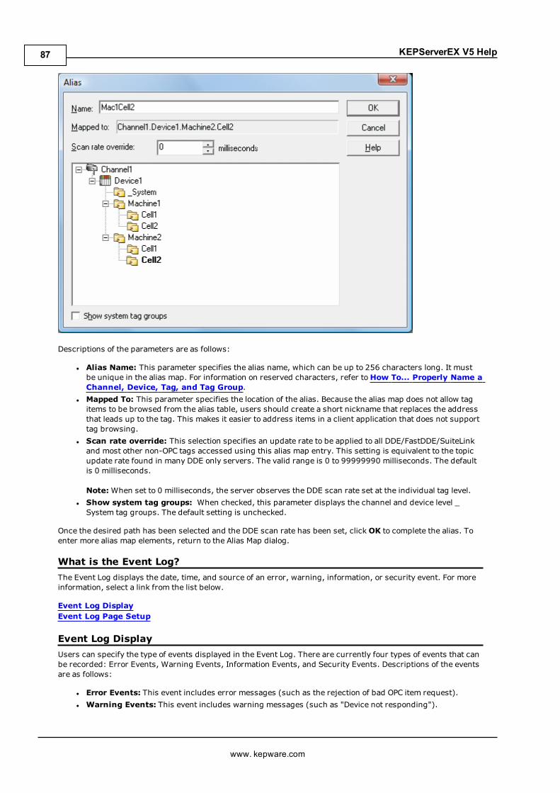
KEPServerEX V5 Help
Descriptions of the parameters are as follows:
l Alias Name: This parameter specifies the alias name, which can be up to 256 characters long. It mustbe unique in the alias map. For information on reserved characters, refer toHow To... Properly Name aChannel, Device, Tag, and Tag Group.
l Mapped To: This parameter specifies the location of the alias. Because the alias map does not allow tagitems to be browsed from the alias table, users should create a short nickname that replaces the addressthat leads up to the tag. This makes it easier to address items in a client application that does not supporttag browsing.
l Scan rate override: This selection specifies an update rate to be applied to all DDE/FastDDE/SuiteLinkand most other non-OPC tags accessed using this alias map entry. This setting is equivalent to the topicupdate rate found in many DDE only servers. The valid range is 0 to 99999990 milliseconds. The defaultis 0 milliseconds.
Note:When set to 0 milliseconds, the server observes the DDE scan rate set at the individual tag level.l Show system tag groups: When checked, this parameter displays the channel and device level _System tag groups. The default setting is unchecked.
Once the desired path has been selected and the DDE scan rate has been set, clickOK to complete the alias. Toenter more alias map elements, return to the Alias Map dialog.
What is the Event Log?The Event Log displays the date, time, and source of an error, warning, information, or security event. For moreinformation, select a link from the list below.
Event Log DisplayEvent Log Page Setup
Event Log DisplayUsers can specify the type of events displayed in the Event Log. There are currently four types of events that canbe recorded: Error Events, Warning Events, Information Events, and Security Events. Descriptions of the eventsare as follows:
l Error Events: This event includes error messages (such as the rejection of bad OPC item request).l Warning Events: This event includes warning messages (such as "Device not responding").
www. kepware.com
87

KEPServerEX V5 Help
l Information Events: This event includes server startup and shutdown messages.l Security Events: This event includes security messages.
Note: To access the event types in the Configuration client, click Tools | Event Log. Alternatively, right-clickanywhere in the Event Log display.
Accessing Through the Tools Menu
Accessing Through the Context Menu
Note: The Event Log system would be useless if there was no mechanism to protect its contents. If operatorscould change these parameters or reset the log, the purpose would be lost. Utilize the User Manager to limit thefunctions an operator can access and prevent these actions from occurring.
See Also:Settings - Event Log
www. kepware.com
88
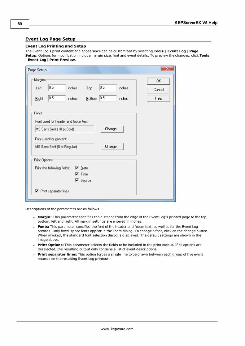
KEPServerEX V5 Help
Event Log Page SetupEvent Log Printing and SetupThe Event Log's print content and appearance can be customized by selecting Tools | Event Log | PageSetup. Options for modification include margin size, font and event details. To preview the changes, click Tools| Event Log | Print Preview.
Descriptions of the parameters are as follows.
l Margin: This parameter specifies the distance from the edge of the Event Log's printed page to the top,bottom, left and right. All margin settings are entered in inches.
l Fonts: This parameter specifies the font of the header and footer text, as well as for the Event Logrecords. Only fixed-space fonts appear in the Fonts dialog. To change a font, click on the change button.When invoked, the standard font selection dialog is displayed. The default settings are shown in theimage above.
l Print Options: This parameter selects the fields to be included in the print output. If all options aredeselected, the resulting output only contains a list of event descriptions.
l Print separator lines: This option forces a single line to be drawn between each group of five eventrecords on the resulting Event Log printout.
www. kepware.com
89

KEPServerEX V5 Help
Tag ManagementThe server's user-defined tag management features can create a tag database structure to fit each application'sspecific nature. Users can define multiple tag groups to segregate tag data on a device-by-device basis, and canalso easily add large numbers of tags through drag and drop editing. CSV import and export also allow tag editingin any application. Like all other server features, new tags can be added to the application at any time.
Automatic Tag Database GenerationThe OPC server's ability to automatically generate tags for select communication drivers brings OPC technologyone step closer to Plug and Play operation. Tag information can be read directly from a device, and tags can alsobe generated from stored tag data. In either case, users no longer need to manually enter OPC tags into theserver.
System TagsSystem tags provide general error feedback to client applications, allow the operation control over when a deviceis actively collecting data, and also permit a channel or device's standard parameters to be changed from an OPCclient application. The number of System tags available at the channel or device level depends on the nature ofthe driver being used.
Note: System tags can be grouped according to their purpose as both status and control or parametermanipulation.
Property TagsProperty tags are additional tags that can be accessed by any Data Access client by appending the property nameto any fully qualified tag address. When using an OPC client that supports item browsing, users can browse tagproperties by turning on Include tag properties when a client browses the server under OPC DA settings.For more information, refer to Project Properties - OPC DA Settings.
Statistics TagsStatistics tags provide feedback to client applications regarding the operation of the channel communications inthe server. When diagnostics are enabled, seven built-in Statistics tags are available. For more information, refertoOPC Diagnostic Viewer.
Modem TagsModem tags configure modem properties and monitor modem status. They are only available when theConnection Type in Channel Properties is set toModem. For more information, refer to Channel Properties- Communications.
Communication Serialization TagsDriver communications normally occur simultaneously across multiple channels, yielding higher datathroughput. In some applications, however, it is required that only one channel be allowed to communicate at atime. Communication Serialization provides this support. Communication Serialization tags are used to configureand monitor a channel's serialization status. Both the feature and its tags are only available to specific drivers.For more information, refer to the driver's help documentation.
CSV Import and ExportThis server can import and export tag data in a Comma Separated Variable (CSV) file to quickly create tags in anapplication. The CSV functions are only available when a device or tag group is selected.
Note: For information on which character to specify as the variable, refer toOptions - General.
To jump to a specific section, select a link from the list below.
Exporting a Server Tag ListImporting a Server Tag List into the ServerUsing Other Characters as the Delimiter
Creating a TemplateThe easiest way to create and import CSV file is to create a template. For more information, refer to theinstructions below.
1. To start, click File | Export CSV. Then, define the channels and devices for the project.
2. Define a tag for each device.
www. kepware.com
90

KEPServerEX V5 Help
3. Next, export each device or tag group as a CSV file.
4. Use this template in a spreadsheet application that supports CSV files and then modify the file as desired.
Note: The resulting CSV file can be saved to disk and re-imported into the server under the same (ornew) device or tag group.
Exporting a Server Tag ListExporting a server tag list generates a .CSV text file that contains a heading record followed by a record for eachtag defined under the selected device or tag group. The heading record contains the following fields:
l Tag Name: The name of the tag as referenced in an OPC client.
Note: The tag namemay contain a group name prefix that is separated from the tag name with a period.For example, a tag name of "Group1.Tag1" creates a group named "Group1" that contains "Tag1".
l Address: The device location referenced by the tag.l Data Type: The data type used for the tag as shown in the server tag's data type drop-down list.l Respect Data Type: This forces the tag to follow its defined data type, not the OPC client request (1, 0).l Client Access: Read/write access (read only and read/write).l Scan Rate: The rate in milliseconds at which the tag address is scanned when used with most non-OPCclients.
l Scaling: Scaling mode (None, Linear, and Square Root).l Raw Low: Low raw value.l Raw High: High raw value.l Scaled Low: Scaled low value.l Scaled High: Scaled high value.l Scaled Data Type: The data type used for the tag after scaling is applied.l Clamp Low: Forces the resulting scaled value to stay within the limit of Scaled Low (1, 0).l Clamp High: Forces the resulting scaled value to stay within the limit of Scaled High (1, 0).l Eng. Units: Units string.l Description: The description of the tag.l Negate Value: Negates the resulting value before being passed to the client when scaling is applied (1,0).
Note: Each tag record contains the data for each field.
Microsoft Excel is an excellent tool for editing large groups of tags outside the server. Once a template CSV filehas been exported, it can be loaded directly into Excel for editing. A CSV file load in Excel would appear as shownin the image below.
www. kepware.com
91
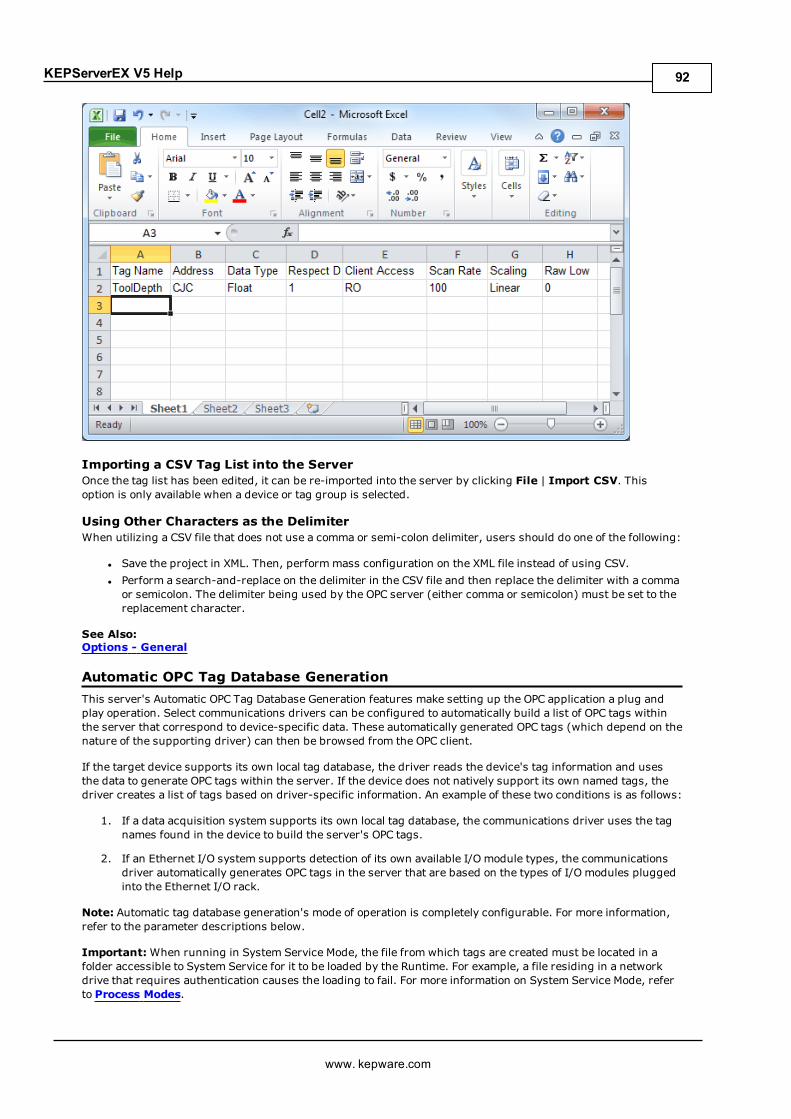
KEPServerEX V5 Help
Importing a CSV Tag List into the ServerOnce the tag list has been edited, it can be re-imported into the server by clicking File | Import CSV. Thisoption is only available when a device or tag group is selected.
Using Other Characters as the DelimiterWhen utilizing a CSV file that does not use a comma or semi-colon delimiter, users should do one of the following:
l Save the project in XML. Then, performmass configuration on the XML file instead of using CSV.l Perform a search-and-replace on the delimiter in the CSV file and then replace the delimiter with a commaor semicolon. The delimiter being used by the OPC server (either comma or semicolon) must be set to thereplacement character.
See Also:Options - General
Automatic OPC Tag Database GenerationThis server's Automatic OPC Tag Database Generation features make setting up the OPC application a plug andplay operation. Select communications drivers can be configured to automatically build a list of OPC tags withinthe server that correspond to device-specific data. These automatically generated OPC tags (which depend on thenature of the supporting driver) can then be browsed from the OPC client.
If the target device supports its own local tag database, the driver reads the device's tag information and usesthe data to generate OPC tags within the server. If the device does not natively support its own named tags, thedriver creates a list of tags based on driver-specific information. An example of these two conditions is as follows:
1. If a data acquisition system supports its own local tag database, the communications driver uses the tagnames found in the device to build the server's OPC tags.
2. If an Ethernet I/O system supports detection of its own available I/O module types, the communicationsdriver automatically generates OPC tags in the server that are based on the types of I/O modules pluggedinto the Ethernet I/O rack.
Note: Automatic tag database generation's mode of operation is completely configurable. For more information,refer to the parameter descriptions below.
Important:When running in System Service Mode, the file from which tags are created must be located in afolder accessible to System Service for it to be loaded by the Runtime. For example, a file residing in a networkdrive that requires authentication causes the loading to fail. For more information on System Service Mode, referto Process Modes.
www. kepware.com
92
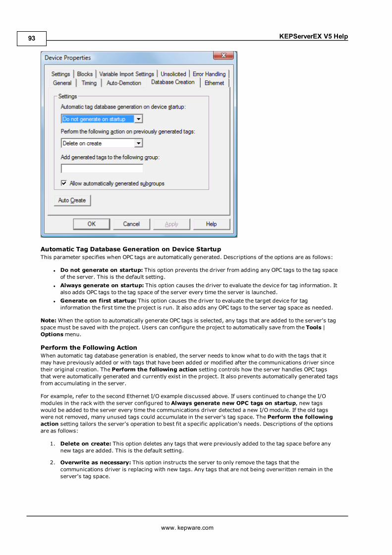
KEPServerEX V5 Help
Automatic Tag Database Generation on Device StartupThis parameter specifies when OPC tags are automatically generated. Descriptions of the options are as follows:
l Do not generate on startup: This option prevents the driver from adding any OPC tags to the tag spaceof the server. This is the default setting.
l Always generate on startup: This option causes the driver to evaluate the device for tag information. Italso adds OPC tags to the tag space of the server every time the server is launched.
l Generate on first startup: This option causes the driver to evaluate the target device for taginformation the first time the project is run. It also adds any OPC tags to the server tag space as needed.
Note:When the option to automatically generate OPC tags is selected, any tags that are added to the server's tagspace must be saved with the project. Users can configure the project to automatically save from the Tools |Optionsmenu.
Perform the Following ActionWhen automatic tag database generation is enabled, the server needs to know what to do with the tags that itmay have previously added or with tags that have been added or modified after the communications driver sincetheir original creation. The Perform the following action setting controls how the server handles OPC tagsthat were automatically generated and currently exist in the project. It also prevents automatically generated tagsfrom accumulating in the server.
For example, refer to the second Ethernet I/O example discussed above. If users continued to change the I/Omodules in the rack with the server configured to Always generate new OPC tags on startup, new tagswould be added to the server every time the communications driver detected a new I/O module. If the old tagswere not removed, many unused tags could accumulate in the server's tag space. The Perform the followingaction setting tailors the server's operation to best fit a specific application's needs. Descriptions of the optionsare as follows:
1. Delete on create: This option deletes any tags that were previously added to the tag space before anynew tags are added. This is the default setting.
2. Overwrite as necessary: This option instructs the server to only remove the tags that thecommunications driver is replacing with new tags. Any tags that are not being overwritten remain in theserver's tag space.
www. kepware.com
93

KEPServerEX V5 Help
3. Do not overwrite: This option prevents the server from removing any tags that were previouslygenerated or already existed in the server. The communications driver can only add tags that arecompletely new.
4. Do not overwrite, log error: This option has the same effect as the third option, and also posts an errormessage to the server's Event Log when a tag overwrite would have occurred.
Note: Removing OPC tags affects tags that have been automatically generated by the communications driver aswell as any tags that have been added using names that match generated tags. Users should avoid adding tags tothe server using names that may match tags that are automatically generated by the driver.
Add Generated Tags to the Following GroupThis parameter keeps automatically generated tags frommixing with tags that have been entered manually. Itspecifies a subgroup to be used when adding all automatically generated tags. The name of the subgroup can beup to 256 characters in length. As shown in the images below, this parameter provides a root branch to which allautomatically generated tags are added.
Note: In this image, the parameter was left blank.
www. kepware.com
94

KEPServerEX V5 Help
Note: In this image, the parameter specified "MyGroup".
Allow Automatically Generated SubgroupsThis parameter controls whether the server automatically creates subgroups for the automatically generatedtags.
Checked The server automatically generates the device's tags and organizes them into subgroups. In theserver project, the resulting tags retain their tag names.
Note: This is the default setting.Unchecked The server automatically generates the device's tags in a list without any subgrouping. In the
server project, the resulting tags are named with the address value. For example, the tag namesare not retained during the generation process. The image below shows how the tag names werecreated using the tag's address.
www. kepware.com
95

KEPServerEX V5 Help
Note: If, as the server is generating tags, a tag is assigned the same name as an existing tag,the system automatically increments to the next highest number so that the tag name is notduplicated. For example, if the generation process creates a tag named "AI22" that alreadyexists, it creates the tag as "AI23" instead.
Auto CreateThis button manually initiates the creation of automatically generated OPC tags. If the device's configuration hasbeen modified, clicking Auto Create forces the communications driver to reevaluate the device for possible tagchanges. Its ability to be accessed from the System tags allows OPC client application to initiate tag databasecreation.
Note: The Auto-Create button is disabled when the Configuration edits a project offline.
Important:With the server's online full-time operation, these parameters can be changed at any time. Utilizethe User Manager to restrict access rights to server features to prevent operators from changing the parameters.
System TagsSystem tags provide general error feedback to client applications, allow operational control when a device isactively collecting data, and allow a channel or device's standard parameters to be changed by an OPC clientapplication when needed.
The number of system tags available at both the channel level and device level depends on the nature of thedriver being used. In addition, application-level system tags allow client applications to monitor the server'sstatus. System tags can also be grouped according to their purpose as both status and control or parametermanipulation. Descriptions are as follows:
l Status Tags: Status tags are read-only tags that provide data on server operation.l Parameter Control Tags: Parameter control tags can be used to modify the server application'soperational characteristics. This provides a great deal of flexibility in the OPC applications. By using theparameter control tags, users can implement redundancy by switching communications links or changingthe device ID of a target device. Users can also provide access to the tags through special supervisoryscreens that allow a plant engineer to make changes to the communication parameters of the server ifneeded.
The tables below include descriptions of the following:
Application-Level System TagsChannel-Level System Tags for Serial Port DriversChannel-Level System Tags for Ethernet DriversDevice-Level System Tags for both Serial and Ethernet Drivers
Application-Level System TagsSyntax Example: <Channel Name>.<Device Name>._System._ActiveTagCount
Tag Class Description_ActiveTagCount Status Tag The _ActiveTagCount tag indicates the number of tags
that are currently active in the server.
This is a read-only tag._ClientCount Status Tag The _ClientCount tag indicates the number of clients that
are currently connected to the server.
This is a read-only tag.
www. kepware.com
96

KEPServerEX V5 Help
_Date Status Tag The _Date tag indicates the current date of the systemthat the server is running on. The format of this string isdefined by the operating system date/time settings.
This is a read-only tag._DateTime Status Tag The _DateTime tag indicates the GMT date and time of the
system that the server is running on. The format of thestring is '2004-05-21T20:39:07.000'.
This is a read-only tag._DateTimeLocal Status Tag The _DateTimeLocal tag indicates the localized date and
time of the system that the server is running on. Theformat of the string is '2004-05-21T16:39:07.000'.
This is a read-only tag._Date_Day Status Tag The _Date_Day tag indicates the current day of the month
of the system on which the server is running.
This is a read-only tag._Date_Month Status Tag The _Date_Month tag indicates the current month of the
system on which the server is running. The format of thestring is a number (such as "9" instead of "September").
This is a read-only tag._Date_Year2 Status Tag The _Date_Year2 tag indicates the last two digits of the
current year of the system on which the server isrunning.
This is a read-only tag._Date_Year4 Status Tag The _Date_Year4 tag indicates the current year of the
system on which the server is running.
This is a read-only tag._FullProjectName Status Tag The _FullProjectName tag indicates the fully qualified
path and file name to the currently loaded project.
This is a read-only tag._IsDemo Status Tag The _IsDemo tag indicates whether the server is running
in Demo Mode. When True, the Demo timer is running.When False, either the product is licensed or the productis unlicensed but a licensable action has not yet occurred.
This is a read-only tag._OpcClientNames Status Tag The _OpcClientNames tag is a String Array that lists the
names of all OPC clients that connect to the server andregister their name through theIOPCCommon::SetClientNamemethod.
This is a read-only tag._ProjectName Status Tag The _ProjectName tag indicates the currently loaded
project file name and does not include path information.
This is a read-only tag._ProjectTitle Status Tag The _ProjectTitle tag is a String tag that indicates the title
of the project that is currently loaded.
This is a read-only tag._Time Status Tag The _Time tag indicates the current time of the system
that the server is running on. The format of this string isdefined by the operating system date/time settings.
This is a read-only tag.
www. kepware.com
97
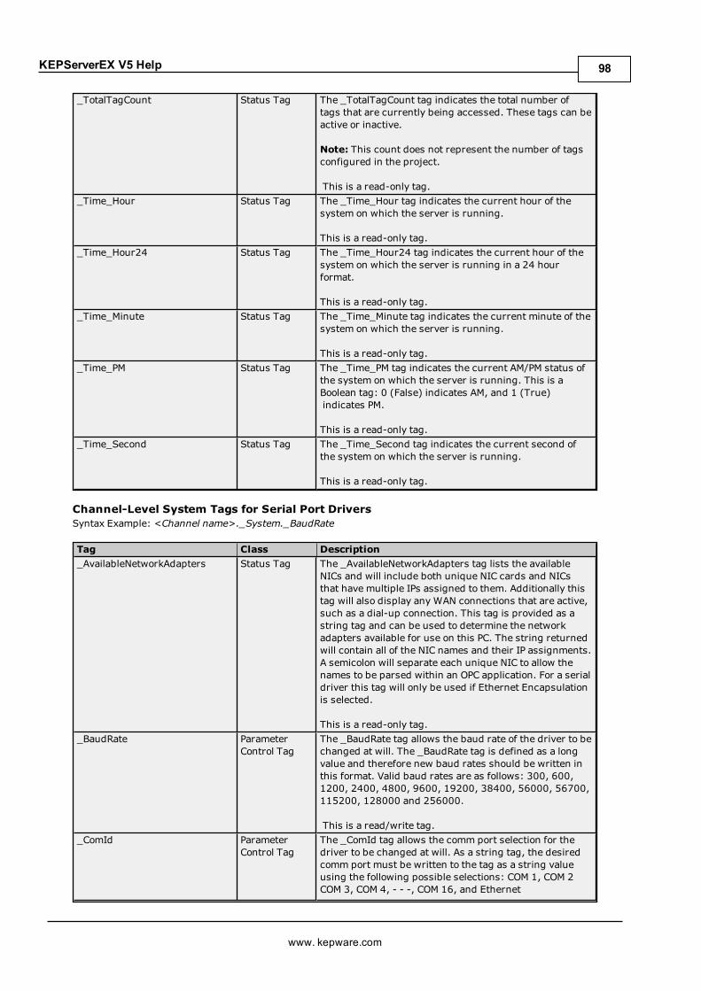
KEPServerEX V5 Help
_TotalTagCount Status Tag The _TotalTagCount tag indicates the total number oftags that are currently being accessed. These tags can beactive or inactive.
Note: This count does not represent the number of tagsconfigured in the project.
This is a read-only tag._Time_Hour Status Tag The _Time_Hour tag indicates the current hour of the
system on which the server is running.
This is a read-only tag._Time_Hour24 Status Tag The _Time_Hour24 tag indicates the current hour of the
system on which the server is running in a 24 hourformat.
This is a read-only tag._Time_Minute Status Tag The _Time_Minute tag indicates the current minute of the
system on which the server is running.
This is a read-only tag._Time_PM Status Tag The _Time_PM tag indicates the current AM/PM status of
the system on which the server is running. This is aBoolean tag: 0 (False) indicates AM, and 1 (True) indicates PM.
This is a read-only tag._Time_Second Status Tag The _Time_Second tag indicates the current second of
the system on which the server is running.
This is a read-only tag.
Channel-Level System Tags for Serial Port DriversSyntax Example: <Channel name>._System._BaudRate
Tag Class Description_AvailableNetworkAdapters Status Tag The _AvailableNetworkAdapters tag lists the available
NICs and will include both unique NIC cards and NICsthat have multiple IPs assigned to them. Additionally thistag will also display any WAN connections that are active,such as a dial-up connection. This tag is provided as astring tag and can be used to determine the networkadapters available for use on this PC. The string returnedwill contain all of the NIC names and their IP assignments.A semicolon will separate each unique NIC to allow thenames to be parsed within an OPC application. For a serialdriver this tag will only be used if Ethernet Encapsulationis selected.
This is a read-only tag._BaudRate Parameter
Control TagThe _BaudRate tag allows the baud rate of the driver to bechanged at will. The _BaudRate tag is defined as a longvalue and therefore new baud rates should be written inthis format. Valid baud rates are as follows: 300, 600,1200, 2400, 4800, 9600, 19200, 38400, 56000, 56700,115200, 128000 and 256000.
This is a read/write tag._ComId Parameter
Control TagThe _ComId tag allows the comm port selection for thedriver to be changed at will. As a string tag, the desiredcomm port must be written to the tag as a string valueusing the following possible selections: COM 1, COM 2COM 3, COM 4, - - -, COM 16, and Ethernet
www. kepware.com
98
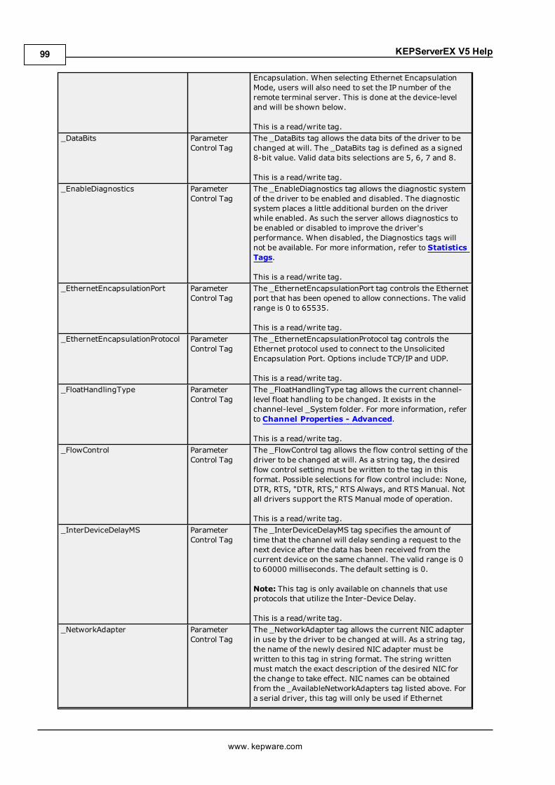
KEPServerEX V5 Help
Encapsulation. When selecting Ethernet EncapsulationMode, users will also need to set the IP number of theremote terminal server. This is done at the device-leveland will be shown below.
This is a read/write tag._DataBits Parameter
Control TagThe _DataBits tag allows the data bits of the driver to bechanged at will. The _DataBits tag is defined as a signed8-bit value. Valid data bits selections are 5, 6, 7 and 8.
This is a read/write tag._EnableDiagnostics Parameter
Control TagThe _EnableDiagnostics tag allows the diagnostic systemof the driver to be enabled and disabled. The diagnosticsystem places a little additional burden on the driverwhile enabled. As such the server allows diagnostics tobe enabled or disabled to improve the driver'sperformance. When disabled, the Diagnostics tags willnot be available. For more information, refer to StatisticsTags.
This is a read/write tag._EthernetEncapsulationPort Parameter
Control TagThe _EthernetEncapsulationPort tag controls the Ethernetport that has been opened to allow connections. The validrange is 0 to 65535.
This is a read/write tag._EthernetEncapsulationProtocol Parameter
Control TagThe _EthernetEncapsulationProtocol tag controls theEthernet protocol used to connect to the UnsolicitedEncapsulation Port. Options include TCP/IP and UDP.
This is a read/write tag._FloatHandlingType Parameter
Control TagThe _FloatHandlingType tag allows the current channel-level float handling to be changed. It exists in thechannel-level _System folder. For more information, referto Channel Properties - Advanced.
This is a read/write tag._FlowControl Parameter
Control TagThe _FlowControl tag allows the flow control setting of thedriver to be changed at will. As a string tag, the desiredflow control setting must be written to the tag in thisformat. Possible selections for flow control include: None,DTR, RTS, "DTR, RTS," RTS Always, and RTS Manual. Notall drivers support the RTS Manual mode of operation.
This is a read/write tag._InterDeviceDelayMS Parameter
Control TagThe _InterDeviceDelayMS tag specifies the amount oftime that the channel will delay sending a request to thenext device after the data has been received from thecurrent device on the same channel. The valid range is 0to 60000 milliseconds. The default setting is 0.
Note: This tag is only available on channels that useprotocols that utilize the Inter-Device Delay.
This is a read/write tag._NetworkAdapter Parameter
Control TagThe _NetworkAdapter tag allows the current NIC adapterin use by the driver to be changed at will. As a string tag,the name of the newly desired NIC adapter must bewritten to this tag in string format. The string writtenmust match the exact description of the desired NIC forthe change to take effect. NIC names can be obtainedfrom the _AvailableNetworkAdapters tag listed above. Fora serial driver, this tag will only be used if Ethernet
www. kepware.com
99
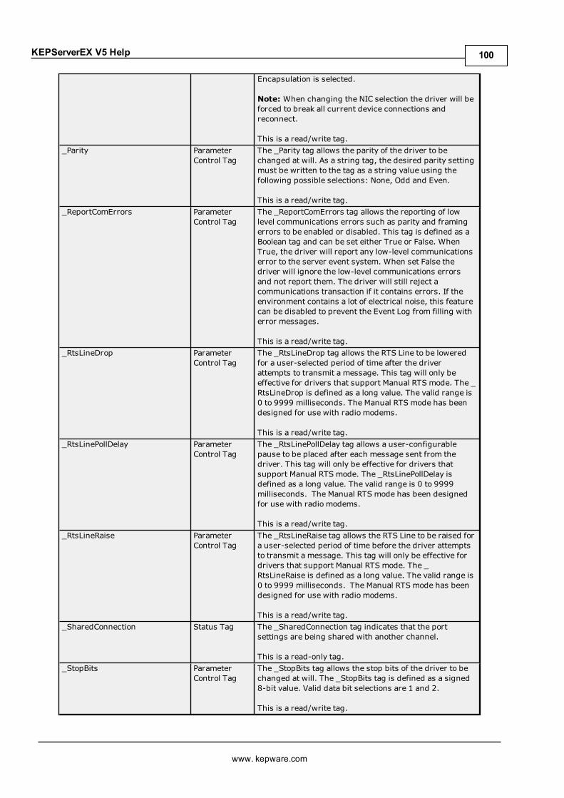
KEPServerEX V5 Help
Encapsulation is selected.
Note: When changing the NIC selection the driver will beforced to break all current device connections andreconnect.
This is a read/write tag._Parity Parameter
Control TagThe _Parity tag allows the parity of the driver to bechanged at will. As a string tag, the desired parity settingmust be written to the tag as a string value using thefollowing possible selections: None, Odd and Even.
This is a read/write tag._ReportComErrors Parameter
Control TagThe _ReportComErrors tag allows the reporting of lowlevel communications errors such as parity and framingerrors to be enabled or disabled. This tag is defined as aBoolean tag and can be set either True or False. WhenTrue, the driver will report any low-level communicationserror to the server event system. When set False thedriver will ignore the low-level communications errorsand not report them. The driver will still reject acommunications transaction if it contains errors. If theenvironment contains a lot of electrical noise, this featurecan be disabled to prevent the Event Log from filling witherror messages.
This is a read/write tag._RtsLineDrop Parameter
Control TagThe _RtsLineDrop tag allows the RTS Line to be loweredfor a user-selected period of time after the driverattempts to transmit a message. This tag will only beeffective for drivers that support Manual RTS mode. The _RtsLineDrop is defined as a long value. The valid range is0 to 9999 milliseconds. The Manual RTS mode has beendesigned for use with radio modems.
This is a read/write tag._RtsLinePollDelay Parameter
Control TagThe _RtsLinePollDelay tag allows a user-configurablepause to be placed after each message sent from thedriver. This tag will only be effective for drivers thatsupport Manual RTS mode. The _RtsLinePollDelay isdefined as a long value. The valid range is 0 to 9999milliseconds. The Manual RTS mode has been designedfor use with radio modems.
This is a read/write tag._RtsLineRaise Parameter
Control TagThe _RtsLineRaise tag allows the RTS Line to be raised fora user-selected period of time before the driver attemptsto transmit a message. This tag will only be effective fordrivers that support Manual RTS mode. The _RtsLineRaise is defined as a long value. The valid range is0 to 9999 milliseconds. The Manual RTS mode has beendesigned for use with radio modems.
This is a read/write tag._SharedConnection Status Tag The _SharedConnection tag indicates that the port
settings are being shared with another channel.
This is a read-only tag._StopBits Parameter
Control TagThe _StopBits tag allows the stop bits of the driver to bechanged at will. The _StopBits tag is defined as a signed8-bit value. Valid data bit selections are 1 and 2.
This is a read/write tag.
www. kepware.com
100

KEPServerEX V5 Help
_WriteOptimizationDutyCycle ParameterControl Tag
The _WriteOptimizationDutyCycle tag allows the dutycycle of the write to read ratio to be changed at will. Theduty cycle controls how many writes the driver will do foreach read it performs. The _WriteOptimizationDutyCycleis defined as an unsigned long value. The valid range is 1to 10 write per read. For more information, refer toChannel Properties - Write Optimizations.
This is a read/write tag.
Channel-Level System Tags for Ethernet DriversSyntax Example: <Channel name>._System._NetworkAdapter
Tag Class Description_AvailableNetworkAdapters Status Tag The _AvailableNetworkAdapters tag lists the available
NICs and includes both unique NIC cards and NICs thathave multiple IPs assigned to them. Additionally this tagalso displays any WAN connections that are active, suchas a dial-up connection. This tag is provided as a stringtag and can be used to determine the network adaptersavailable for use on this PC. The string returned containsall of the NIC names and their IP assignments. Asemicolon separates each unique NIC to allow the namesto be parsed within an OPC application. For a serial driver,this tag is only used if Ethernet Encapsulation is selected.
This is a read-only tag._EnableDiagnostics Parameter
Control TagThe _EnableDiagnostics tag allows the diagnostic systemof the driver to be enabled and disabled. The diagnosticsystem places a little additional burden on the driverwhile enabled. As such the server allows diagnostics tobe enabled or disabled to improve the driver'sperformance. When disabled, the Diagnostics tags willnot be available. For more information, refer to StatisticsTags.
This is a read/write tag._FloatHandlingType Parameter
Control TagThe _FloatHandlingType tag allows the current channel-level float handling to be changed. It exists in thechannel-level _System folder. For more information, referto Channel Properties - Advanced.
This is a read/write tag._InterDeviceDelayMS Parameter
Control TagThe _InterDeviceDelayMS tag specifies the amount oftime that the channel will delay sending a request to thenext device after the data has been received from thecurrent device on the same channel. The valid range is 0to 60000 milliseconds. The default setting is 0.
Note: This tag is only available on channels that useprotocols that utilize the Inter-Device Delay.
This tag is a read/write tag._NetworkAdapter Parameter
Control TagThe _NetworkAdapter tag allows the current NIC adapterin use by the driver to be changed at will. As a string tag,the name of the newly desired NIC adapter must bewritten to this tag in string format. The string writtenmust match the exact description of the desired NIC forthe change to take effect. NIC names can be obtainedfrom the _AvailableNetworkAdapters tag listed above. Fora serial driver, this tag will only be used if EthernetEncapsulation is selected.
www. kepware.com
101
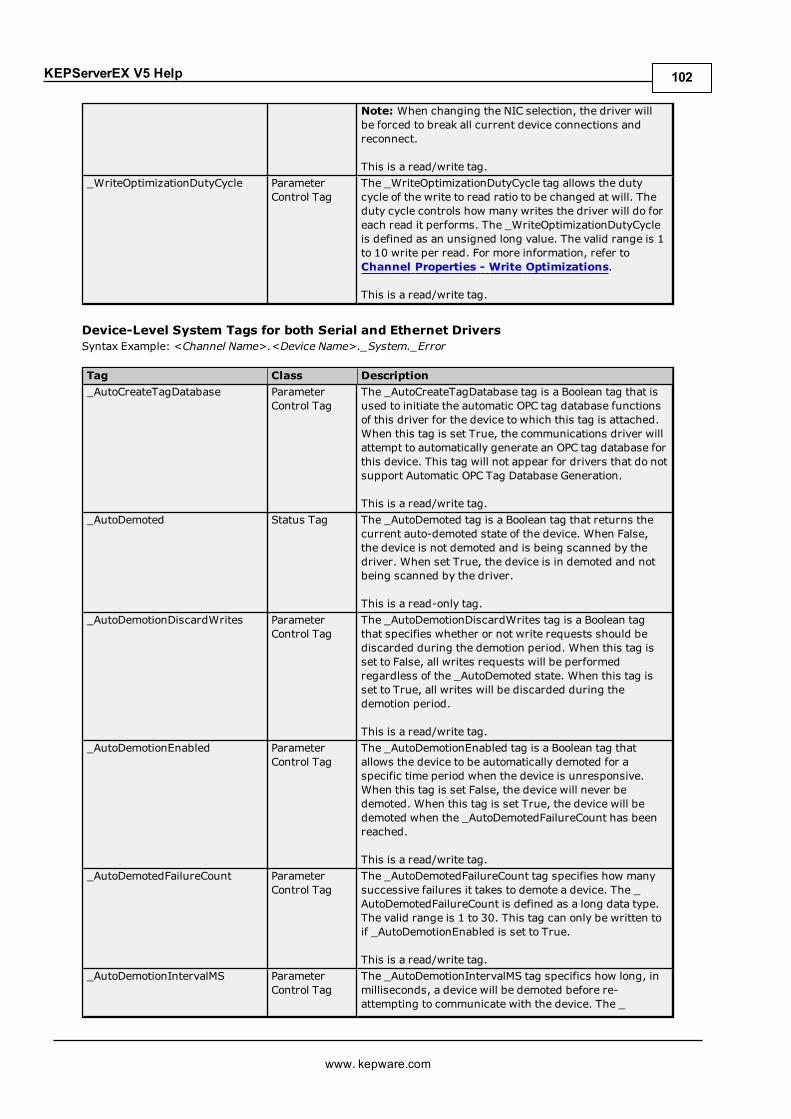
KEPServerEX V5 Help
Note: When changing the NIC selection, the driver willbe forced to break all current device connections andreconnect.
This is a read/write tag._WriteOptimizationDutyCycle Parameter
Control TagThe _WriteOptimizationDutyCycle tag allows the dutycycle of the write to read ratio to be changed at will. Theduty cycle controls how many writes the driver will do foreach read it performs. The _WriteOptimizationDutyCycleis defined as an unsigned long value. The valid range is 1to 10 write per read. For more information, refer toChannel Properties - Write Optimizations.
This is a read/write tag.
Device-Level System Tags for both Serial and Ethernet DriversSyntax Example: <Channel Name>.<Device Name>._System._Error
Tag Class Description_AutoCreateTagDatabase Parameter
Control TagThe _AutoCreateTagDatabase tag is a Boolean tag that isused to initiate the automatic OPC tag database functionsof this driver for the device to which this tag is attached.When this tag is set True, the communications driver willattempt to automatically generate an OPC tag database forthis device. This tag will not appear for drivers that do notsupport Automatic OPC Tag Database Generation.
This is a read/write tag._AutoDemoted Status Tag The _AutoDemoted tag is a Boolean tag that returns the
current auto-demoted state of the device. When False,the device is not demoted and is being scanned by thedriver. When set True, the device is in demoted and notbeing scanned by the driver.
This is a read-only tag._AutoDemotionDiscardWrites Parameter
Control TagThe _AutoDemotionDiscardWrites tag is a Boolean tagthat specifies whether or not write requests should bediscarded during the demotion period. When this tag isset to False, all writes requests will be performedregardless of the _AutoDemoted state. When this tag isset to True, all writes will be discarded during thedemotion period.
This is a read/write tag._AutoDemotionEnabled Parameter
Control TagThe _AutoDemotionEnabled tag is a Boolean tag thatallows the device to be automatically demoted for aspecific time period when the device is unresponsive.When this tag is set False, the device will never bedemoted. When this tag is set True, the device will bedemoted when the _AutoDemotedFailureCount has beenreached.
This is a read/write tag._AutoDemotedFailureCount Parameter
Control TagThe _AutoDemotedFailureCount tag specifies how manysuccessive failures it takes to demote a device. The _AutoDemotedFailureCount is defined as a long data type.The valid range is 1 to 30. This tag can only be written toif _AutoDemotionEnabled is set to True.
This is a read/write tag._AutoDemotionIntervalMS Parameter
Control TagThe _AutoDemotionIntervalMS tag specifics how long, inmilliseconds, a device will be demoted before re-attempting to communicate with the device. The _
www. kepware.com
102

KEPServerEX V5 Help
AutoDemotionIntervalMS is defined as a long data type.The valid range is 100 to 3600000 milliseconds. This tagcan only be written to if _AutoDemotionEnabled is set toTrue.
This is a read/write tag._ConnectTimeout Parameter
Control TagThe _ConnectTimeout tag allows the timeout associatedwith making an IP connection to a device to be changed atwill. This tag is available when either a native Ethernetdriver is in use or a serial driver is in EthernetEncapsulation mode. The _ConnectTimeout is defined asa Long data type. The valid range is 1 to 30 seconds.
This is a read/write tag._DemandPoll Status /
Control TagThe _DemandPoll tag issues a device read to all the activeclient items associated with the device. This is theequivalent of a client performing an asynchronous deviceread for those items. It takes priority over any scheduledreads that are supposed to occur for items that are beingactively scanned.
The _DemandPoll tag becomes True (1) when written to.It returns to False (0) when the final active tag signalsthat the read requests have completed. Subsequentwrites to the _DemandPoll tag will fail until the tag valuereturns to False. The demand poll respects the read/writeduty cycle for the channel.
This is a read/write tag._DeviceId Parameter
Control TagThe _DeviceId tag allows the ID of the device to bechanged at will. The data format of the _DeviceIddepends on the type of device. For most serial devicesthis tag will be a Long data type. For Ethernet drivers the_DeviceId will be formatted as a string tag, allowing theentry of an IP address. In either case, writing a newdevice ID to this tag will cause the driver to change thetarget field device. This will only occur if the device IDwritten to this tag is correctly formatted and within thevalid range for the given driver.
This is a read/write tag._Enabled Parameter
Control TagThe _Enabled tag is a Boolean tag that allows the activestate of the device to be turned On or Off. When this tagis set False, all other user-defined tags and data from thisdevice will be marked as invalid and writes will not beaccepted for the device. When this tag is set True, normalcommunications will occur with the device.
This is a read/write tag._EncapsulationIp Parameter
Control TagThe _EncapsulationIp tag allows the IP of a remoteterminal server to be specified and changed at will. Thistag is only available on serial drivers that support DeviceProperties - Ethernet Encapsulation mode. The _EncapsulationIp is defined as a string data type, allowingthe entry of an IP address number. The server will rejectentry of invalid IP addresses. This tag is only valid for aserial driver in Ethernet Encapsulation mode.
This is a read/write tag._EncapsulationPort Parameter
Control TagThe _EncapsulationPort tag allows the port number of theremote terminal server to be specified and changed atwill. The _EncapsulationPort is defined as a long datatype. The valid range is 0 to 65535. The port numberentered in this tag must match that of the desired remote
www. kepware.com
103
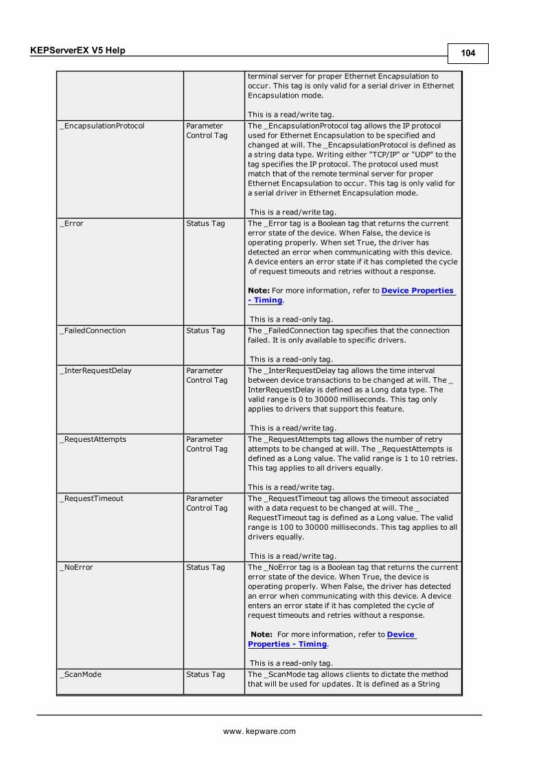
KEPServerEX V5 Help
terminal server for proper Ethernet Encapsulation tooccur. This tag is only valid for a serial driver in EthernetEncapsulation mode.
This is a read/write tag._EncapsulationProtocol Parameter
Control TagThe _EncapsulationProtocol tag allows the IP protocolused for Ethernet Encapsulation to be specified andchanged at will. The _EncapsulationProtocol is defined asa string data type. Writing either "TCP/IP" or "UDP" to thetag specifies the IP protocol. The protocol used mustmatch that of the remote terminal server for properEthernet Encapsulation to occur. This tag is only valid fora serial driver in Ethernet Encapsulation mode.
This is a read/write tag._Error Status Tag The _Error tag is a Boolean tag that returns the current
error state of the device. When False, the device isoperating properly. When set True, the driver hasdetected an error when communicating with this device.A device enters an error state if it has completed the cycleof request timeouts and retries without a response.
Note: For more information, refer toDevice Properties- Timing.
This is a read-only tag._FailedConnection Status Tag The _FailedConnection tag specifies that the connection
failed. It is only available to specific drivers.
This is a read-only tag._InterRequestDelay Parameter
Control TagThe _InterRequestDelay tag allows the time intervalbetween device transactions to be changed at will. The _InterRequestDelay is defined as a Long data type. Thevalid range is 0 to 30000 milliseconds. This tag onlyapplies to drivers that support this feature.
This is a read/write tag._RequestAttempts Parameter
Control TagThe _RequestAttempts tag allows the number of retryattempts to be changed at will. The _RequestAttempts isdefined as a Long value. The valid range is 1 to 10 retries.This tag applies to all drivers equally.
This is a read/write tag._RequestTimeout Parameter
Control TagThe _RequestTimeout tag allows the timeout associatedwith a data request to be changed at will. The _RequestTimeout tag is defined as a Long value. The validrange is 100 to 30000 milliseconds. This tag applies to alldrivers equally.
This is a read/write tag._NoError Status Tag The _NoError tag is a Boolean tag that returns the current
error state of the device. When True, the device isoperating properly. When False, the driver has detectedan error when communicating with this device. A deviceenters an error state if it has completed the cycle ofrequest timeouts and retries without a response.
Note: For more information, refer toDeviceProperties - Timing.
This is a read-only tag._ScanMode Status Tag The _ScanMode tag allows clients to dictate the method
that will be used for updates. It is defined as a String
www. kepware.com
104
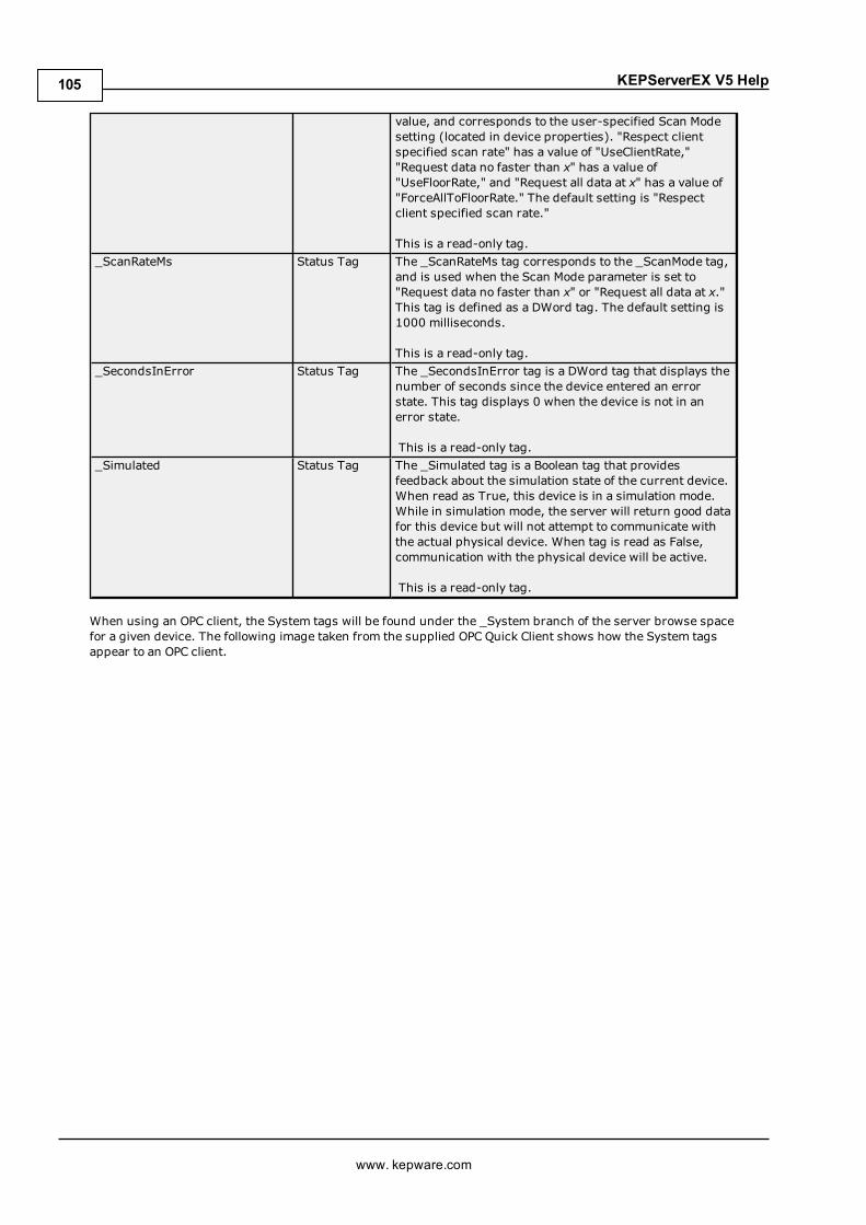
KEPServerEX V5 Help
value, and corresponds to the user-specified Scan Modesetting (located in device properties). "Respect clientspecified scan rate" has a value of "UseClientRate,""Request data no faster than x" has a value of"UseFloorRate," and "Request all data at x" has a value of"ForceAllToFloorRate." The default setting is "Respectclient specified scan rate."
This is a read-only tag._ScanRateMs Status Tag The _ScanRateMs tag corresponds to the _ScanMode tag,
and is used when the Scan Mode parameter is set to"Request data no faster than x" or "Request all data at x."This tag is defined as a DWord tag. The default setting is1000 milliseconds.
This is a read-only tag._SecondsInError Status Tag The _SecondsInError tag is a DWord tag that displays the
number of seconds since the device entered an errorstate. This tag displays 0 when the device is not in anerror state.
This is a read-only tag._Simulated Status Tag The _Simulated tag is a Boolean tag that provides
feedback about the simulation state of the current device.When read as True, this device is in a simulation mode.While in simulation mode, the server will return good datafor this device but will not attempt to communicate withthe actual physical device. When tag is read as False,communication with the physical device will be active.
This is a read-only tag.
When using an OPC client, the System tags will be found under the _System branch of the server browse spacefor a given device. The following image taken from the supplied OPC Quick Client shows how the System tagsappear to an OPC client.
www. kepware.com
105

KEPServerEX V5 Help
The _System branch found under the DeviceName branch is always available. If referencing a system tag from aDDE application given the above example and the DDE defaults, the link would appear as "<DDE service name>|_ddedata!Channel1.Device1._System._Error".
The _Enabled tag provides a very flexible means of controlling the OPC applications. In some cases, specifically inmodem applications, it can be convenient to disable all devices except the device currently connected to themodem. Additionally, using the _Enable tag to allow the application to turn a particular device off while thephysical device is being serviced can eliminate harmless but unwanted communications errors in the server'sEvent Log.
See Also:Property TagsModem TagsStatistics Tags
Property TagsProperty tags are used to provide read-only access to tag properties for client applications. To access a tagproperty, append the property name to the fully qualified tag address that has been defined in the server's tagdatabase. For more information, refer to Tag Properties - General.
If the fully qualified tag address is "Channel1.Device1.Tag1," its description can be accessed by appending thedescription property as "Channel1.Device1.Tag1._Description".
Supported Property Tag NamesTag Name Description_Name The _Name property tag indicates the current name for the tag it is referencing._Address The _Address property tag indicates the current address for the tag it is
referencing._Description The _Description property tag indicates the current description for the tag it is
referencing._RawDataType The _RawDataType property tag indicates the raw data type for the tag it is
referencing.
www. kepware.com
106
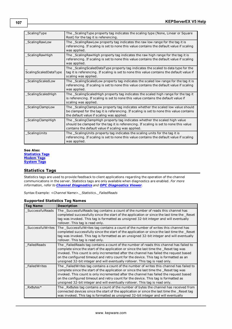
KEPServerEX V5 Help
_ScalingType The _ScalingType property tag indicates the scaling type (None, Linear or SquareRoot) for the tag it is referencing.
_ScalingRawLow The _ScalingRawLow property tag indicates the raw low range for the tag it isreferencing. If scaling is set to none this value contains the default value if scalingwas applied.
_ScalingRawHigh The _ScalingRawHigh property tag indicates the raw high range for the tag it isreferencing. If scaling is set to none this value contains the default value if scalingwas applied.
_ScalingScaledDataType
The _ScalingScaledDataType property tag indicates the scaled to data type for thetag it is referencing. If scaling is set to none this value contains the default value ifscaling was applied.
_ScalingScaledLow The _ScalingScaledLow property tag indicates the scaled low range for the tag it isreferencing. If scaling is set to none this value contains the default value if scalingwas applied.
_ScalingScaledHigh The _ScalingScaledHigh property tag indicates the scaled high range for the tag itis referencing. If scaling is set to none this value contains the default value ifscaling was applied.
_ScalingClampLow The _ScalingClampLow property tag indicates whether the scaled low value shouldbe clamped for the tag it is referencing. If scaling is set to none this value containsthe default value if scaling was applied.
_ScalingClampHigh The _ScalingClampHigh property tag indicates whether the scaled high valueshould be clamped for the tag it is referencing. If scaling is set to none this valuecontains the default value if scaling was applied.
_ScalingUnits The _ScalingUnits property tag indicates the scaling units for the tag it isreferencing. If scaling is set to none this value contains the default value if scalingwas applied.
See Also:Statistics TagsModem TagsSystem Tags
Statistics TagsStatistics tags are used to provide feedback to client applications regarding the operation of the channelcommunications in the server. Statistics tags are only available when diagnostics are enabled. For moreinformation, refer to Channel Diagnostics and OPC Diagnostics Viewer.
Syntax Example: <Channel Name>._Statistics._FailedReads
Supported Statistics Tag NamesTag Name Description_SuccessfulReads The _SuccessfulReads tag contains a count of the number of reads this channel has
completed successfully since the start of the application or since the last time the _Resettag was invoked. This tag is formatted as unsigned 32-bit integer and will eventuallyrollover. This tag is read only.
_SuccessfulWrites The _SuccessfulWrites tag contains a count of the number of writes this channel hascompleted successfully since the start of the application or since the last time the _Resettag was invoked. This tag is formatted as an unsigned 32-bit integer and will eventuallyrollover. This tag is read only.
_FailedReads The _FailedReads tag contains a count of the number of reads this channel has failed tocomplete since the start of the application or since the last time the _Reset tag wasinvoked. This count is only incremented after the channel has failed the request basedon the configured timeout and retry count for the device. This tag is formatted as anunsigned 32-bit integer and will eventually rollover. This tag is read only.
_FailedWrites The _FailedWrites tag contains a count of the number of writes this channel has failed tocomplete since the start of the application or since the last time the _Reset tag wasinvoked. This count is only incremented after the channel has failed the request basedon the configured timeout and retry count for the device. This tag is formatted asunsigned 32-bit integer and will eventually rollover. This tag is read only.
_RxBytes* The _RxBytes tag contains a count of the number of bytes the channel has received fromconnected devices since the start of the application or since the last time the _Reset tagwas invoked. This tag is formatted as unsigned 32-bit integer and will eventually
www. kepware.com
107
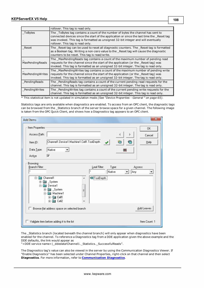
KEPServerEX V5 Help
rollover. This tag is read only._TxBytes The _TxBytes tag contains a count of the number of bytes the channel has sent to
connected devices since the start of the application or since the last time the _Reset tagwas invoked. This tag is formatted as unsigned 32-bit integer and will eventuallyrollover. This tag is read only.
_Reset The _Reset tag can be used to reset all diagnostic counters. The _Reset tag is formattedas a Boolean tag. Writing a non-zero value to the _Reset tag will cause the diagnosticcounters to be reset. This tag is read/write.
_MaxPendingReads
The _MaxPendingReads tag contains a count of the maximum number of pending readrequests for the channel since the start of the application (or the _Reset tag) wasinvoked. This tag is formatted as an unsigned 32-bit integer. The tag is read only.
_MaxPendingWrites
The _MaxPendingWrites tag contains a count of the maximum number of pending writerequests for the channel since the start of the application (or the _Reset tag) wasinvoked. This tag is formatted as an unsigned 32-bit integer. The tag is read only.
_PendingReads The _PendingReads tag contains a count of the current pending read requests for thechannel. This tag is formatted as an unsigned 32-bit integer. The tag is read only.
_PendingWrites The _PendingWrites tag contains a count of the current pending write requests for thechannel. This tag is formatted as an unsigned 32-bit integer. This tag is read only.
* This statistical item is not updated in simulation mode (See "Device Properties - General " on page 65).
Statistics tags are only available when diagnostics are enabled. To access from an OPC client, the diagnostic tagscan be browsed from the _Statistics branch of the server browse space for a given channel. The following imageis taken from the OPC Quick Client, and shows how a Diagnostics tag appears to an OPC client.
The _Statistics branch (located beneath the channel branch) will only appear when diagnostics have beenenabled for the channel. To reference a Diagnostics tag from a DDE application given the above example and theDDE defaults, the link would appear as"<DDE service name>|_ddedata!Channel1._Statistics._SuccessfulReads".
The Diagnostics tag's value can also be viewed in the server by using the Communication Diagnostics Viewer. If"Enable Diagnostics" has been selected under Channel Properties, right-click on that channel and then selectDiagnostics. For more information, refer to Communication Diagnostics.
www. kepware.com
108
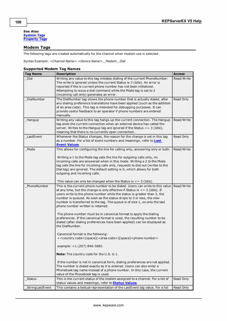
KEPServerEX V5 Help
See Also:System TagsProperty Tags
Modem TagsThe following tags are created automatically for the channel when modem use is selected.
Syntax Example: <Channel Name>.<Device Name>._Modem._Dial
Supported Modem Tag NamesTag Name Description Access_Dial Writing any value to this tag initiates dialing of the current PhoneNumber.
The write is ignored unless the current Status is 3 (Idle). An error isreported if the is current phone number has not been initialized.Attempting to issue a dial command while the Mode tag is set to 2(incoming call only) generates an error.
Read/Write
_DialNumber The DialNumber tag shows the phone number that is actually dialed, afterany dialing preference translations have been applied (such as the additionof an area code). This tag is intended for debugging purposes. It canprovide useful feedback to an operator if phone numbers are enteredmanually.
Read Only
_Hangup Writing any value to this tag hangs up the current connection. The Hanguptag ends the current connection when an external device has called theserver. Writes to the Hangup tag are ignored if the Status <= 3 (Idle),meaning that there is no currently open connection.
Read/Write
_LastEvent Whenever the Status changes, the reason for the change is set in this tagas a number. For a list of event numbers and meanings, refer to LastEvent Values.
Read Only
_Mode This allows for configuring the line for calling only, answering only or both.
Writing a 1 to the Mode tag sets the line for outgoing calls only, noincoming calls are answered when in this mode. Writing a 2 to the Modetag sets the line for incoming calls only, requests to dial out (writes to theDial tag) are ignored. The default setting is 0, which allows for bothoutgoing and incoming calls.
This value can only be changed when the Status is <= 3 (Idle).
Read/Write
_PhoneNumber This is the current phone number to be dialed. Users can write to this valueat any time, but the change is only effective if Status is <= 3 (Idle). Ifusers write to the phone number while the status is greater than 3, thenumber is queued. As soon as the status drops to 3 or less, the newnumber is transferred to the tag. The queue is of size 1, so only the lastphone number written is retained.
The phone number must be in canonical format to apply the dialingpreferences. If the canonical format is used, the resulting number to bedialed (after dialing preferences have been applied) can be displayed asthe DialNumber.
Canonical format is the following:+<country code>[space](<area code>)[space]<phone number>
example: +1 (207) 846-5881
Note: The country code for the U.S. is 1.
If the number is not in canonical form, dialing preferences are not applied.The number is dialed exactly as it is entered. Users can also enter aPhonebook tag name instead of a phone number. In this case, the currentvalue of the Phonebook tag is used.
Read/Write
_Status This is the current status of the modem assigned to a channel. For a list ofstatus values and meanings, refer to Status Values.
Read Only
_StringLastEvent This contains a textual representation of the LastEvent tag value. For a list Read Only
www. kepware.com
109

KEPServerEX V5 Help
of event numbers and meanings, refer to Last Event String Values._StringStatus This contains a textual representation of the Status tag value. For a list of
event numbers and meanings, refer to Status String Values.Read Only
Status ValuesThe five lowest bits of the 32-bit status variable are currently being used.
Bit Meaning0 Initialized with TAPI1 Line open2 Connected3 Calling4 Answering
When read as an integer, the value of the Status tag is always one of the following:
Value Meaning0 Un-initialized, the channel is not usable1 Initialized, no line open3 Line open and the state is idle7 Connected11 Calling19 Answering
Status String ValuesStatus Value StringStatus Text0 Uninitialized, channel is unusable1 Initialized, no line open3 Idle7 Connected11 Calling19 Answering
Last Event ValuesLastEvent Reason for Change-1 <blank> [no events have occurred yet]0 Initialized with TAPI1 Line closed2 Line opened3 Line connected4 Line dropped by user5 Line dropped at remote site6 No answer7 Line busy8 No dial tone9 Incoming call detected10 User dialed11 Invalid phone number12 Hardware error on line caused line close
Last Event String ValuesLastEvent StringLastEvent-1 <blank> [no events have occurred yet]0 Initialized with TAPI1 Line closed2 Line opened
www. kepware.com
110

KEPServerEX V5 Help
3 Line connected4 Line dropped by user5 Line dropped at remote site6 No answer7 Line busy8 No dial tone9 Incoming call detected10 User dialed11 Invalid phone number12 Hardware error on line caused line close13 Unable to dial
Communication Serialization TagsSyntax Example: <Channel Name>._CommunicationSerialization._VirtualNetwork
Tag Description_NetworkOwner
Class: Status Tag
The _NetworkOwner tag indicates if the channel currently ownscontrol of communications on the network. The frequency ofchange reflects how often the channel is granted control.
This tag is read only._Registered
Class: Status Tag
The _Registered tag indicates whether the channel is currentlyregistered to a virtual network. After setting the _VirtualNetwork,the channel unregisters from the network it is currently registeredto (indicated in _RegisteredTo) when it is capable of doing so. Inother words, if the channel owns control during the switch, itcannot unregister until it has released control. Upon unregistering,the channel registers with new virtual network. This tag is FALSE if_VirtualNetwork is None.
This tag is read only._RegisteredTo
Class: Status Tag
The _RegisteredTo tag indicates the virtual network to which thechannel is currently registered. After setting the _VirtualNetwork,the channel unregisters from the network it is currently registeredto when it is capable of doing so. In other words, if the channelowns control during the switch, it cannot unregister until it hasreleased control. Upon unregistering, the channel registers withnew virtual network. This tag indicates if there are delays switchingnetworks as _VirtualNetwork and _RegisteredTo could differ for aperiod of time. This tag is N/A if _VirtualNetwork is None.
This tag is read only._StatisticAvgNetworkOwnershipTimeSec
Class: Status Tag
The _StatisticAvgNetworkOwnershipTimeSec tag indicates howlong on average the channel holds ownership of control since thestart of the application (or since the last time _StatisticsReset waswritten to). This tag helps identify busy channels/bottlenecks. Thistag is formatted as a 32-bit floating point and may eventuallyrollover.
This tag is read only._StatisticNetworkOwnershipCount
Class: Status Tag
The _StatisticNetworkOwnershipCount tag indicates the number oftimes the channel has been granted control of communicationssince the start of the application (or since the last time _StatisticsReset was written to). This tag is formatted as anunsigned 32-bit integer and may eventually rollover.
This tag is read only._StatisticNetworkOwnershipTimeSec
Class: Status Tag
The _StatisticNetworkOwnershipTimeSec tag indicates how long inseconds the channel has held ownership since the start of theapplication (or since the last time _StatisticsReset was written to).This tag is formatted as a 32-bit floating point and may eventually
www. kepware.com
111
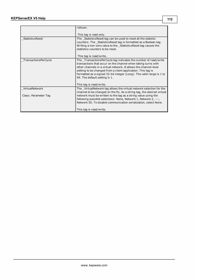
KEPServerEX V5 Help
rollover.
This tag is read only._StatisticsReset The _StatisticsReset tag can be used to reset all the statistic
counters. The _StatisticsReset tag is formatted as a Boolean tag.Writing a non-zero value to the _StatisticsReset tag causes thestatistics counters to be reset.
This tag is read/write._TransactionsPerCycle The _TransactionsPerCycle tag indicates the number of read/write
transactions that occur on the channel when taking turns withother channels in a virtual network. It allows the channel-levelsetting to be changed from a client application. This tag isformatted as a signed 32-bit integer (Long). The valid range is 1 to99. The default setting is 1.
This tag is read/write._VirtualNetwork
Class: Parameter Tag
The _VirtualNetwork tag allows the virtual network selection for thechannel to be changed on the fly. As a string tag, the desired virtualnetwork must be written to the tag as a string value using thefollowing possible selections: None, Network 1, Network 2, ---,Network 50. To disable communication serialization, select None.
This tag is read/write.
www. kepware.com
112

KEPServerEX V5 Help
Communications ManagementAuto-DemotionThe Auto-Demotion parameters allow a driver to temporarily place a device off-scan in the event that a device isnot responding. By placing a non-responsive device offline, the driver can continue to optimize itscommunications with other devices on the same channel by stopping communications with the non-responsivedevice for a specific time period. After the specific time period has been reached, the driver re-attempts tocommunicate with the non-responsive device. If the device is responsive, the device is placed on-scan;otherwise, it restarts its off-scan time period. For more information, refer toDevice Properties - Auto-Demotion.
Network Interface SelectionAn NIC card can be selected for use with any Ethernet driver or serial driver running in Ethernet Encapsulationmode. The Network Interface feature is used to select a specific NIC card based on either the NIC name or itscurrently assigned IP address. The list of available NICs includes both unique NIC cards and NICs that havemultiple IPs assigned to them. The selection displays any WAN connections that may be active (such as a dial-upconnection).
Ethernet EncapsulationThe Ethernet Encapsulation mode has been designed to provide communications with serial devices connected toterminal servers on the Ethernet network. A terminal server is essentially a virtual serial port: the terminal serverconverts TCP/IP messages on the Ethernet network to serial data. Once the message has been converted to aserial form, users can connect standard devices that support serial communications to the terminal server. Usinga terminal server device allows users to place RS-232 and RS-485 devices throughout the plant operations whilestill allowing a single localized PC to access the remotely mounted devices. Furthermore, the EthernetEncapsulation mode allows an individual network IP address to be assigned to each device as needed. By usingmultiple terminal servers, users can access hundreds of serial devices from a single PC via the Ethernet network.For more information, refer toHow Do I... and Device Properties - Ethernet Encapsulation.
Modem SupportThis server supports the use of modems to connect to remote devices, which is established through the use ofspecial modem tags that become available at the channel-level when a dial-up network connection has beencreated. These channel-level modem tags can be used to dial a remote device, monitor the modem status whileconnected and terminate the call when completed.
Note: Not all serial drivers support the use of modems. To determine modem support, refer to the specificdriver's help documentation.
When accessing the new modem tags, the channel name can be used as either a base group or topic name. If theproject contains more than one channel definition, users need to configure the channel names so that each isunique. This remains true for device names, as well. Channel names can no longer match the device name whenthe project needs to be configured to use a modem. The channel name requirements do not apply to projects thatare not using a modem.
To be used, modems must be configured with the operating system through the Control Panel settings. Forspecific setup information, refer to the Windows and modem documentation. Once the modem has been properlyinstalled, it can be enabled by selecting the Use Modem checkbox in the channel wizard.
Important:Many new commercial modems are designed to dial-up network server connections and negotiatethe fastest and clearest signal. When communicating to a serial automation device, the modem needs to connectat a specific Baud (Bits per Second) and Parity. For this reason, an external modem (which can be configured todial using specific Baud Rate and Parity settings) is strongly recommended. To determine the best modem for aspecific application, refer to Technical Support. For examples on how to use a modem in a project, refer toUsinga Modem in the Server Project.
Using a Modem in the Server ProjectModems convert serial data from the RS-232 port into signal levels that can be transmitted over the phone line.To do this, they break down each byte of the serial data into bits that are used to generate the signal transmitted.Most modems can convert up to 10 bits of information for every byte of data that is sent. Devices must be able touse 10 bits or less to communicate through a modem. To determine the amount of bits being used by a specificdevice, refer to the formula below.
Start Bits + Data Bits + Parity + Stop Bits = Total Bit Count
www. kepware.com
113
KEPServerEX V5 Help
For example, the Modbus RTU Driver is configured to use 8 Data Bits, Even Parity, 1 Stop Bit, and 1 Start Bit.When plugged into the formula, it would be 1 + 8 + 1 + 1, which equals 11 bits. A normal modem could nottransmit data to this Modbus device. If Parity is changed to None, it would be 1 + 8 + 0 + 1, which equals 10Bits. A normal modem could transmit data to this Modbus device.
Some drivers cannot be configured to use a 10-bit or less data format, and so cannot use standard modems.Instead, they require modems that can handle transmitting 11 data bits. For drivers that fall into this category,consult the device's manufacturer for recommendations on an appropriate modem vendor. Modem operation isenabled for all serial drivers regardless of their suitability for modem operation.
Configuring the Initiating ModemThis server uses the Windows TAPI interface to access modems attached to the PC. The TAPI interface wasdesigned to provide Windows programs a common interface that could be accessed by a range of modemsexisting in a PC. A set of drivers provided by the modem's manufacturer for the Windows OS must be installedbefore the server can use the modem in a project. The Windows Control Panel can be used to install newmodems. For information regarding modem installation and setup, refer to both the Windows and the modem'shelp documentation.
Once the modem has been properly installed, users can begin using it in a server project. The receiving end, orthe device modem, must be properly configured before it can be used. Users must confirm that the receivingmodemmatches the profile provided by the driver.
Configuring the Receiving ModemTo easily configure the receiving modem, use the Hyperterminal program that is included with Windows. Formore information, follow the instructions below.
Note: The following example uses a project that specified the connection to use 10 bits or less.
1. To start, use an available serial Port to connect the desired receiving modem to the PC.
2. Next, start Hyperterminal and open a new connection. Name this new connection "ModemSetup".
3. In Connect To, click the Connect Using drop-down menu and then select the communication port towhich the receiving modem is attached. Other modems may appear in this list.
4. In COMx Properties, configure the communications port settings to be used to talk to the receivingmodem.
Important: The COMx properties settings must match the baud rate, data bits, parity, and stop bits usedby the target device. Modems remember the settings that were used to talk to it last; if the receivingmodem was configured at 19,200 baud but the device was configured for 9600 baud, the modem is notable to speak to the device. Although it could connect, the receiving modem would send all the data to thedevice at 19,200 baud. This is true even if the modem connects at 9600 baud or if the transmittingmodem is being spoken to at 9600 baud. Any disparity between the settings causes the modemapplication to fail. To avoid the error, match the settings between the newly created server project andone that has a direct cable connection.
5. Next, enter the port settings. Once finished, clickOK.
Note: At this point, users should be able to issue commands to the receiving modem. On many modems,this can be tested by typing "ATI4" followed by "Enter". If the modem is properly attached to the PC, itresponds by displaying its current profile settings. For information on a specific modem, refer to its helpdocumentation.
6. Set the receiving modem's desired profile and then save the settings by issuing a write command. To doso, type "AT&W0" followed by "Enter".
Note: To test the receiving modem's configuration, turn it off for a moment and turn it back on.
7. Next, type "AT14" followed by "Enter" (or another applicable command). The modem should display itscurrent profile, including any changes that have been made.
Important: The profile settings and reference documents are provided as examples. Due to thedifferences in configuration commands and codes among modemmanufacturers, users should refer tothe modem's help documentation.
Cables
www. kepware.com
114

KEPServerEX V5 Help
Before the project can be used, the cable connection must be configured between the receiving modem and thedevice. Three cables are required: the existing device communication cable for direct connection, a NULL modemadapter, and a NULL modem cable. A NULL modem cable is connected to the modem, and all pins are connectedto the same pins on both ends of the cable. The device communication cable is used to connect to the targetdevice, and usually has pins 2 and 3 reversed. Because the cable being used to talk to the device for the directconnection is working by this point, it can be used on the receiving modem by attaching a NULL modem adapter.Similarly, a PCmodem cable runs from the PC to the initiating modem. With the cables in place, a modem can nowbe used in the application.
Note: NULL modem adapters can be found at most computer stores.
Example: Server Side Modem ConfigurationAfter the modems have been configured and installed, they can be used with the server.
1. To start, load the direct connect project and then double-click on the channel name. In ChannelProperties, open the Communications tab.
2. In the Physical Medium drop-down menu, selectModem. Beneath Modem Settings, select a modemthat is available on the computer.
Note: Users are not able to select Modem from the Physical Medium drop-down menu if there are noneavailable on the computer. If this occurs, exit the server and attempt to reinstall the modem using theModem Configuration tools supplied by the operating system.
3. To configure the initiating modem's characteristics, use the parameters available beneath ModemSettings. For more information, refer to Channel Properties - Communications.
4. Once finished, click Apply. Then, clickOK to save and exit the Channel Properties.
Note: For more information on recommended modem settings, refer to the specific driver's help documentation.
Using a Modem in Your ApplicationOnce modem operation has been enabled, a list of pre-defined tags are available in the driver's tag Window.These Modem tags control and monitor an attached modem, and are contained under the channel name (whichhas become an active OPC access path through which the Modem tags are accessed). Because the server knowsvery little about what the application needs for modem control, it does not imply any type of control. By using thepredefined Modem tags, users can apply the application's scripting capabilities to control how the server usesthe selected modem.
Phonebook TagsA Phonebook tag can be used in place of specifying a telephone number by directly writing to the Phone Numbertag. A Phonebook tag can be created on the channel, along with the other modem system tags previouslydescribed. The data associated with a Phonebook tag is a phone number that can be assigned when the tag iscreated and/or later modified when the server has an active client connection. The phone number stored in aphonebook tag can be used to dial by writing anything to the tag. The act of writing causes the selectedPhonebook tag to dial.
Syntax Example: <Channel Name>._Phonebook.<Phonebook Tag Name>
Data Type PrivilegeString Read/Write
Phonebook tags are entered using the dialog shown below. To add a new Phonebook tag, click on the NewPhonebook icon to display the Phone Number Tags dialog.
www. kepware.com
115

KEPServerEX V5 Help
Modem Auto-DialWhen Modem Auto-Dial has been enabled in the channel, the initial connection request begins by attempting todial the first phone number encountered in the phonebook. If that attempt is unsuccessful, the next number inthe phonebook is attempted and so on. This sequence continues until a modem connection is established or theclient releases all references to data that can be supplied by the channel.
Note: The phone number order is user-defined. To re-order the phone numbers, drag and drop the entries asdesired.
ExampleA Phonebook tag name was created for 'Site1.'
Syntax Example: <Channel Name>.<Device Name>._Phonebook.Site1
Tag Name Description Access<Name ofPhone book tagcreated inModemConfiguration>
Instead of specifying a telephone number by directly writing to the PhoneNumber tag, a Phonebook tag can be used. A Phonebook tag can be created onthe channel, along with the other modem system tags previously described.The data associated with a Phonebook tag is a phone number that can beassigned when the tag is created and/or later modified when the server has anactive client connection. The phone number stored in a Phonebook tag can beused to dial by writing anything to the tag. The act of writing causes theselected Phonebook tag to dial.
Read/Write
Phone Number TagsThe Phone Number dialog is used to enter a new Phonebook tag, which can then be used to dial a desired phonenumber. Phonebook tags keep the list in the server, which is useful if the OPC client application cannot store thephone number for a device location. To invoke a Phonebook tag, the OPC client must write any string value to thedesired Phonebook tag. The phone number dialog should appear as shown below.
www. kepware.com
116

KEPServerEX V5 Help
Descriptions of the parameters are as follows:
l Name: This parameter is used to enter the string to represent the phone number available from thePhonebook tag. Names can be up to 256 characters in length. Although using descriptive names isgenerally a good idea, some OPC client applications may have a limited display window when browsing thetag space of an OPC server. The Phonebook tag name is part of the OPC browse data. Phonebook tagnames must be unique within a given device. For information on reserved characters, refer toHow To...Properly Name a Channel, Device, Tag, and Tag Group.
l Number: This parameter is used to enter the phone number to be dialed when the tag is invoked from anOPC client application. A string of up to 64 digits can be entered.
l Description: This parameter is used to attach a comment to this tag. A string of up to 64 characters canbe entered.
Note:With the server's online full-time operation, these parameters can be changed at any time. Changes madeto tag properties take effect immediately; however, OPC clients that have already connected to this tag are notaffected until they release and reacquire this tag. To prevent operators from changing these parameters use theUser Manager to restrict access rights to server features.
Modem Auto-DialModem Auto-Dial (MAD) automates the actions required of a client application when modem use is specifiedwithin the server project. Without MAD, these actions (which include connecting, disconnecting, and assigningphone numbers) would be performed by an external client application through the use of channel-level Modemtags. For example, to begin the process of establishing a connection, the client would write a dial string to"<channel>._Modem._PhoneNumber" and then write a value to "<channel>._Modem._Dial". When data fromthe remote device is no longer needed, the client would end the call by writing to "<channel>._Modem._Hangup".
Modem Auto-Dial relieves the client of these responsibilities by automatically dialing phone numbers defined inthe Phonebook when attempting to establish a connection. The connection is automatically dropped when thereare no client references to tags that rely on the modem connection. To access the Modem Auto-Dial settings, clickChannel Properties | Communications. For more information, refer to Channel Properties -Communications.
Modem Connection and DisconnectionThe process of establishing a modem connection begins when a client connects to the server Runtime andrequests data from a device connection to a channel on which Modem Auto-Dial is enabled. The initial connectionrequest begins by attempting to dial the first phone number encountered in the phonebook. If that attempt isunsuccessful, the next number in the phonebook is attempted and so on. This sequence continues until a modemconnection is established or the client releases all references to data that can be supplied by the channel.
Note:When re-establishing a connection, the phonebook entry that last produced a successful connection isused. If no previous phonebook entry was successful (or if the entry has since been deleted), the user-definedsequence of phone numbers is used. The number used for re-dialing is not preserved during serverreinitialization or restart.
See Also:Phonebook Tags
TimingTiming settings (such as how long to wait for a connection before proceeding to the next phone number) aredetermined by the TAPI modem configuration and not by any specific Modem Auto-Dial setting.
Note: Some drivers do not allow the serial port to close once it has opened. Connections established using thesedrivers do not experience disconnection until all client references have been released (unless the TAPI settingsare configured to disconnect after a period of idle time).
Client AccessModem tags may be used to exert client-level control over the modem. If Modem Auto-Dialing is enabled,however, write access to the Modem tags is restricted so that only one form of access is possible. The Modemtags' values are updated just as they would if the client were in control of the modem.
Changing the Modem Auto-Dial Settings from the ConfigurationThe runtime reacts to changes in settings according to the following rules:
www. kepware.com
117

KEPServerEX V5 Help
l If MAD is enabled after the client has already dialed the modem and established a connection, the changeis ignored until the modem is disconnected. If the client is still requesting data from the channel at thetime of disconnection, the initial connection sequence begins.
l If MAD is enabled while no modem connection exists and data is being requested from the channel by theclient, the initial connection sequence begins.
l If MAD is disabled while an existing auto-dial connection exists, no action is taken and the connection isdropped.
l If all entries are deleted from the phonebook, MAD is disabled.
See Also:Channel Properties - Communications
www. kepware.com
118
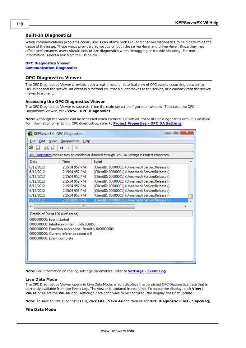
KEPServerEX V5 Help
Built-In DiagnosticsWhen communications problems occur, users can utilize both OPC and channel diagnostics to help determine thecause of the issue. These views provide diagnostics on both the server-level and driver-level. Since they mayaffect performance, users should only utilize diagnostics when debugging or trouble-shooting. For moreinformation, select a link from the list below.
OPC Diagnostics ViewerCommunication Diagnostics
OPC Diagnostics ViewerThe OPC Diagnostics Viewer provides both a real-time and historical view of OPC events occurring between anOPC client and the server. An event is a method call that a client makes to the server, or a callback that the servermakes to a client.
Accessing the OPC Diagnostics ViewerThe OPC Diagnostics Viewer is separate from the main server configuration window. To access the OPCDiagnostics Viewer, click View | OPC Diagnostics.
Note: Although the viewer can be accessed when capture is disabled, there are no diagnostics until it is enabled.For information on enabling OPC diagnostics, refer to Project Properties - OPC DA Settings.
Note: For information on the log settings parameters, refer to Settings - Event Log.
Live Data ModeThe OPC Diagnostics Viewer opens in Live Data Mode, which displays the persisted OPC Diagnostics data that iscurrently available from the Event Log. The viewer is updated in real time. To pause the display, click View |Pause or select the Pause icon. Although data continues to be captured, the display does not update.
Note: To save an OPC Diagnostics file, click File | Save As and then select OPC Diagnostic Files (*.opcdiag).
File Data Mode
www. kepware.com
119
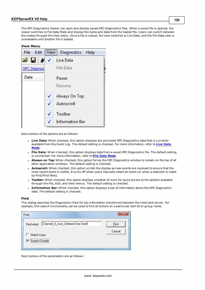
KEPServerEX V5 Help
The OPC Diagnostics Viewer can open and display saved OPC Diagnostics files. When a saved file is opened, theviewer switches to File Data Mode and display the name and data from the loaded file. Users can switch betweenthe modes through the View menu. Once a file is closed, the view switches to Live Data, and the File Data view isunavailable until another file is loaded.
View Menu
Descriptions of the options are as follows:
l Live Data:When checked, this option displays any persisted OPC Diagnostics data that is currentlyavailable from the Event Log. The default setting is checked. For more information, refer to Live DataMode.
l File Data:When checked, this option displays data from a saved OPC Diagnostics file. The default settingis unchecked. For more information, refer to File Data Mode.
l Always on Top:When checked, this option forces the OPC Diagnostics window to remain on the top of allother application windows. The default setting is checked.
l Autoscroll:When checked, this option scrolls the display as new events are received to ensure that themost recent event is visible. It turns off when users manually select an event (or when a selection is madeby Find/Find Next).
l Toolbar:When checked, this option displays a toolbar of icons for quick access to the options availablethrough the File, Edit, and View menus. The default setting is checked.
l Information Bar: When checked, this option displays a bar of information above the OPC Diagnosticsdata. The default setting is checked.
FindThis dialog searches the Diagnostics View for key information transferred between the client and server. Forexample, this search functionality can be used to find all actions on a particular item ID or group name.
Descriptions of the parameters are as follows:
www. kepware.com
120

KEPServerEX V5 Help
l Find What: This field specifies the search criteria.l Match Case:When checked, the search criteria is case sensitive.l Search Details:When checked, the search criteria includes details.
Note:When an event or detail with the specified text is found, the line containing the text is highlighted. Toperform a Find Next operation (and look for the next occurrence of the specified text), press "F3". When the lastoccurrence is found, a message box indicates this condition. Users can change the search criteria at any time bypressing "Ctrl+F".
FilterThis dialog specifies which events is visible in the OPC Diagnostics Viewer. For example, most clients makecontinuous GetStatus calls into the server to determine whether the server is still available. By filtering this event,users can just examine the diagnostics data. The filtering applied is to the view, not to the capture. All eventtypes are captured regardless of the filter settings. Furthermore, because filters can be applied while the dialogis open, settings can be changed and applied independently. Changes may be made without closing andreopening the dialog.
Note: Each method (such as "IOPCCommon" or "GetErrorString") of every OPC Data Access 1.0, 2.0, and 3.0interface that is supported by the server is available as a filter.
Descriptions of the options are as follows:
www. kepware.com
121
KEPServerEX V5 Help
l Select All:When clicked, this button selects all of the events for viewing. To select all methods within aspecific event type, double-click on the topmost event type. All methods for all interfaces are selected bydefault. For more information, refer toOPC Diagnostic Events.
l Deselect All:When clicked, this button deselects all event types and methods.l Import:When clicked, this button allows users to select an INI file for import to the Filter.l Export:When clicked, this button allows users to export the Filter as an INI file.
Notes:
1. Because the Filter settings are persisted when the OPC Diagnostics Viewer is closed, users can reopenand view the OPC diagnostic files at a later time. Files opened in File Data Mode may be filtered. When a fileis saved from the OPC Diagnostics Viewer, only the events that are displayed as a result of the appliedfilter is saved. If an unfiltered data file is required, users must turn off filtering before saving the file.
2. The server's performance is affected when diagnostic information is captured because it is an additionallayer of processing that occurs between the client/server communications. Furthermore, logging OPCDiagnostics in the Extended Datastore Persistence Mode can consume a lot of disk space. The WindowsEvent Viewer reports any related errors. For information on persistence modes, refer to Settings - EventLog.
OPC Diagnostic EventsFor more information on a specific OPC Diagnostic Event, select a link from the list below.
IClassFactoryServerIOPCCommonIOPCServerIConnectionPointContainer (Server)IConnectionPoint (Server)IOPCBrowseIOPCBrowseServerAddressSpaceIOPCItemPropertiesIOPCItemIOGroupIOPCGroupStateMgtIOPCGroupStateMgt2IOPCItemMgtIOPCItemDeadbandMgtIOPCItemSamplingMgtIOPCSyncIOIOPCSyncIO2IOPCAsyncIOIDataObjectIAdviseSinkIAsyncIO2IAsyncIO3IConnectionPointContainer (Group)IConnectionPoint (Group)IOPCDataCallbackIEnumOPCItemAttributes
IClassFactoryThe IClassFactory interface contains several methods intended to deal with an entire class of objects. It isimplemented on the class object for a specific class of objects and is identified by a CLSID.
l QueryInterface: The client can ask the object whether it supports any outgoing interfaces by callingQueryInterface for IConnectionPointContainer. If the object answers "yes" by handing back a validpointer, the client knows it can attempt to establish a connection.
l AddRef: Increments the reference count for an interface on an object. It should be called for every newcopy of a pointer to an interface on a given object.
www. kepware.com
122

KEPServerEX V5 Help
l Release: Decreases the reference count of the interface by 1.l CreateInstance: Creates an uninitialized object.l LockServer: Allows instances to be created quickly when called by the client of a class object to keep aserver open in memory.
ServerThe client calls CoCreateInstance to create the server object and the initial interface.
l QueryInterface: The client can ask the object whether it supports any outgoing interfaces by callingQueryInterface for IConnectionPointContainer. If the object answers "yes" by handing back a validpointer, the client knows it can attempt to establish a connection.
l AddRef: Increments the reference count for an interface on an object. It should be called for every newcopy of a pointer to an interface on a given object.
l Release: Decreases the reference count of the interface by 1.
IOPCCommonThis interface is used by all OPC server types (DataAccess, Alarm&Event, Historical Data, and so forth). Itprovides the ability to set and query a Locale ID which would be in effect for the particular client/server session.The actions of one client do not affect other clients.
l GetErrorString: Returns the error string for a server specific error code. The expected behavior is thatthis includes handling of Win32 errors as well (such as RPC errors).
l GetLocaleID: Returns the default Locale ID for this server/client session.l QueryAvailableLocaleIDs: Returns the available Locale IDs for this server/client session.l SetClientName: Allows the client to optionally register a client name with the server. This is includedprimarily for debugging purposes. The recommended behavior is that users set the Node name and EXEname here.
l SetLocaleID: Sets the default Locale ID for this server/client session. This Locale ID is used by theGetErrorString method on this interface. The default value for the server should be LOCALE_SYSTEM_DEFAULT.
IOPCServerThis is an OPC server's main interface. The OPC server is registered with the operating system as specified in theInstallation and Registration Chapter of this specification.
l AddGroup: Adds a group to a server. A group is a logical container for a client to organize and manipulatedata items.
l CreateGroupEnumerator: Creates various enumerators for the groups provided by the server.l GetErrorString: Returns the error string for a server specific error code.l GetGroupByName: Returns an additional interface pointer when given the name of a private group(created earlier by the same client). Use GetPublicGroupByName to attach to public groups. This functioncan be used to reconnect to a private group for which all interface pointers have been released.
l GetStatus: Returns current status information for the server.l RemoveGroup: Deletes the group. A group is not deleted when all the client interfaces are released,since the server itself maintains a reference to the group. The client may still call GetGroupByName afterall the interfaces have been released. RemoveGroup() causes the server to release its 'last' reference tothe group, which results in the group being deleted.
IConnectionPointContainer (Server)This interface provides the access to the connection point for IOPCShutdown.
l EnumConnectionPoints: Creates an enumerator for the connection points supported between the OPCgroup and the client. OPCServers must return an enumerator that includes IOPCShutdown. Additionalvendor specific callbacks are allowed.
l FindConnectionPoint: Finds a particular connection point between the OPC server and the client.OPCServers must support IID_IOPCShutdown. Additional vendor specific callbacks are allowed.
IConnectionPoint (Server)This interface establishes a call back to the client.
www. kepware.com
123

KEPServerEX V5 Help
l Advise: Establishes an advisory connection between the connection point and the caller's sink object.l EnumConnections: Creates an enumerator object for iteration through the connections that exist to thisconnection point.
l GetConnectionInterface: Returns the IID of the outgoing interface managed by this connection point.l GetConnectionPointContainer: Retrieves the IConnectionPointContainer interface pointer to theconnectable object that conceptually owns the connection point.
l Unadvise: Terminates an advisory connection previously established through the Advise method.l ShutdownRequest: Allows the server to request that all clients disconnect from the server.
IOPCBrowseIOPCBrowse interface provides improved methods for browsing the server address space and for obtaining theitem properties.
l GetProperties: Returns an array of OPCITEMPROPERTIES, one for each item ID.l Browse: Browses a single branch of the address space and returns zero or more OPCBROWSEELEMENTstructures.
IOPCBrowseServerAddressSpaceThis interface provides a way for clients to browse the available data items in the server, giving the user a list ofthe valid definitions for an item ID. It allows for either flat or hierarchical address spaces and is designed to workwell over a network. It also insulates the client from the syntax of a server vendor specific item ID.
l BrowseAccessPaths: Provides a way to browse the available AccessPaths for an item ID.l BrowseOPCItemIDs: Returns an IENUMString for a list of item IDs as determined by the passedparameters. The position from which the browse is made can be set in ChangeBrowsePosition.
l ChangeBrowserPosition: Provides a way to move up, down or to in a hierarchical space.l GetItemID: Provides a way to assemble a fully qualified item ID in a hierarchical space. This is requiredsince the browsing functions return only the components or tokens that make up an item ID and do notreturn the delimiters used to separate those tokens. Also, at each point one is browsing just the namesbelow the current node (e.g. the units in a cell).
l QueryOrganization: Provides a way to determine if the underlying system is inherently flat orhierarchical and how the server may represent the information of the address space to the client. Flat andhierarchical spaces behave somewhat different. If the result is flat then the client knows that there is noneed to pass the Branch or Leaf flags to BrowseOPCItem IDs or to call ChangeBrowsePosition.
IOPCItemPropertiesThis interface can be used to browse the available properties associated with an item ID as well as to read theproperties' current values.
l GetItemProperties: Returns a list of the current data values for the passed ID codes.l LookUpItemIDs: Returns a list of item IDs for each of the passed ID codes if any are available. Theseindicate the item ID which could be added to an OPC group and used for more efficient access to the datacorresponding to the item properties.
l QueryAvailableProperties: Returns a list of ID codes and descriptions for the available properties forthis item ID. This list may differ for different item IDs. This list is expected to be relatively stable for aparticular item ID, although it could be affected from time to time by changes to the underlying system'sconfiguration. The item ID is passed to this function because servers are allowed to return different setsof properties for different item IDs.
IOPCItemIOThe purpose of this interface is to provide an easy way for basic applications to obtain OPC data.
l Read: Reads one or more values, qualities, and timestamps for the items specified. This is functionallysimilar to the IOPCSyncIO::Read method.
l WriteVQT:Writes one or more values, qualities, and timestamps for the items specified. This isfunctionally similar to the IOPCSyncIO2::WriteVQT except that there is no associated group. If a clientattempts to write VQ, VT, or VQT it should expect that the server will write them all or none at all.
GroupThe client calls CoCreateInstance to create the server object and the initial interface.
www. kepware.com
124
KEPServerEX V5 Help
l QueryInterface: The client can ask the object whether it supports any outgoing interfaces by callingQueryInterface for IConnectionPointContainer. If the object answers "yes" by handing back a validpointer, the client knows it can attempt to establish a connection.
l AddRef: Increments the reference count for an interface on an object. It should be called for every newcopy of a pointer to an interface on a given object.
l Release: Decreases the reference count of the interface by 1.
IOPCGroupStateMgtIOPCGroupStateMgt allows the client to manage the overall state of the group. Primarily, this accounts forchanges made to the group's update rate and active state.
l CloneGroup: Creates a second copy of a group with a unique name.l GetState: Gets the current state of the group. This function is typically called to obtain the currentvalues of this information prior to calling SetState. This information was all supplied by or returned to theclient when the group was created.
l SetName: Changes the name of a private group. The namemust be unique. The name cannot bechanged for public groups. Group names are required to be unique with respect to an individual client toserver connection.
l SetState: Sets various properties of the group. This represents a new group which is independent of theoriginal group.
IOPCGroupStateMgt2This interface was added to enhance the existing IOPCGroupStateMgt interface.
l SetKeepAlive: Causes the server to provide client callbacks on the subscription when there are no newevents to report. Clients can then be assured of the health of the server and subscription withoutresorting to pinging the server with calls to GetStatus().
l GetKeepAlive: Returns the currently active keep-alive time for the subscription.
IOPCItemMgtThis interface allows a client to add, remove and control the behavior of items is a group.
l AddItems: Adds one or more items to a group. It is acceptable to add the same item to the group morethan once, generating a second item with a unique ServerHandle.
l CreateEnumerator: Creates an enumerator for the items in the group.l RemoveItems: Removes items from a group. Removing items from a group does not affect the addressspace of the server or physical device. It indicates whether or not the client is interested in thoseparticular items.
l SetActiveState: Sets one or more items in a group to active or inactive. This controls whether or notvalid data can be obtained from read cache for those items and whether or not they are included in theIAdvise subscription to the group. Deactivating items does not result in a callback, since by definitioncallbacks do not occur for inactive items. Activating items generally results in an IAdvise callback at thenext UpdateRate period.
l SetClientHandles: Changes the client handle for one or more items in a group. In general, it is expectedthat clients set the client handle when the item is added and not change it later.
l SetDataTypes: Changes the requested data type for one or more items in a group. In general, it isexpected that clients set the requested datatype when the item is added and not change it later.
l ValidateItems: Determines if an item is valid and could be added without error. It also returnsinformation about the item such as canonical datatype. It does not affect the group in any way.
IOPCItemDeadbandMgtForce a callback to IOPCDataCallback::OnDataChange for all active items in the group, whether they havechanged or not. Inactive items are not included in the callback. The MaxAge value determines where the data isobtained. There is only one MaxAge value, which determines the MaxAge for all active items in the group. Thismeans some of the values may be obtained from cache while others could be obtained from the device, dependingon the "freshness" of the data in the cache.
l SetItemDeadband: Overrides the deadband specified for the group for each item.l GetItemDeadband: Gets the deadband values for each of the requested items.l ClearItemDeadband: Clears the individual item PercentDeadband, effectively reverting them back to thedeadband value set in the group.
www. kepware.com
125

KEPServerEX V5 Help
IOPCItemSamplingMgtThis optional interface allows the client to manipulate the rate at which individual items within a group areobtained from the underlying device. It does not affect the group update rate of the callbacks for OnDataChange.
l SetItemSamplingRate: Sets the sampling rate on individual items. This overrides the update rate of thegroup as far as collection from the underlying device is concerned. The update rate associated withindividual items does not affect the callback period.
l GetItemSamplingRate: Gets the sampling rate on individual items, which was previously set withSetItemSamplingRate.
l ClearItemSamplngRate: Clears the sampling rate on individual items, which was previously set withSetItemSamplingRate. The item reverts to the update rate of the group.
l SetItemBufferEnable: Requests that the server turns on or off, depending on the value of the Enableparameter, the buffering of data for the identified items, which are collected for items that have an updaterate faster than the group update rate.
l GetItemBufferEnable: Queries the current state of the servers buffering for requested items.
IOPCSyncIOIOPCSyncIO allows a client to perform synchronous read and write operations to a server. The operations run tocompletion.
l Read: Reads the value, quality and timestamp information for one or more items in a group. The functionruns to completion before returning. The data can be read from cache in which case it should be accurateto within the UpdateRate and percent deadband of the group. The data can be read from the device, inwhich case an actual read of the physical device must be performed. The exact implementation of cacheand device reads are not defined by the specification.
l Write:Writes values to one or more items in a group. The function runs to completion. The values arewritten to the device, meaning that the function should not return until it verifies that the device hasactually accepted or rejected the data. Writes are not affected by the active state of the group or item.
IOPCSyncIO2This interface was added to enhance the existing IOPCSyncIO interface.
l ReadMaxAge: Reads one or more values, qualities and timestamps for the items specified. This isfunctionally similar to the OPCSyncIO::Read method except no source is specified (device or cache). Theserver determines whether the information is obtained from the device or cache. This decision is based onthe MaxAge parameter. If the information in the cache is within the MaxAge, the data is obtained from thecache; otherwise, the server must access the device for the requested information.
l WriteVQT:Writes one or more values, qualities and timestamps for the items specified. This isfunctionally similar to the IOPCSyncIO::Write except that Quality and Timestamp may be written. If aclient attempts to write VQ, VT or VQT it should expect that the server will write to all or none.
IOPCAsyncIOIOPCAsyncIO allows a client to perform asynchronous read and write operations to a server. The operations arequeued and the function returns immediately so that the client can continue to run. Each operation is treated as atransaction and is associated with a Transaction ID. As the operations are completed, a callback is made to theIAdvise Sink in the client (if one is established). The information in the callback indicates the Transaction ID andthe error results. By convention, 0 is an invalid Transaction ID.
l Cancel: Requests that the server cancel an outstanding transaction.l Read: Reads one or more items in a group. The results are returned via the IAdvise Sink connectionestablished through the IDataObject. For cache reads the data is only valid if both the group and the itemare active. Device reads are not affected by the active state of the group or item.
l Refresh: Forces a callback for all active items in the group, whether they have changed or not. Inactiveitems are not included in the callback.
l Write:Writes one or more items in a group. The results are returned via the IAdviseSink connectionestablished through the IDataObject.
IDataObjectIDataObject is implemented on the OPCGroup rather than on the individual items. This allows the creation of anAdvise connection between the client and the group using the OPC Data Stream Formats for the efficient datatransfer.
www. kepware.com
126
KEPServerEX V5 Help
l DAdvise: Creates a connection for a particular stream format between the OPC group and the client.l DUnadvise: Terminates a connection between the OPC group and the client.
IAdviseSinkThe client only has to provide a full implementation of OnDataChange.
l OnDataChange: This method is provided by the client to handle notifications from the OPC group forexception based data changes, Async reads and Refreshes and Async Write Complete.
IAsyncIO2This interface is similar to IOPCAsync(OPC 1.0) and is intended to replace IOPCAsyncIO. It was added in OPC2.05.
l Cancel2: Requests that the server cancel an outstanding transaction.l GetEnable: Retrieves the last Callback Enable value set with SetEnable.l Read: Reads one or more items in a group. The results are returned via the client's IOPCDataCallbackconnection established through the server's IConnectionPointContainer. Reads are from device and arenot affected by the active state of the group or item.
l Refresh2: Forces a callback to IOPCDataCallback::OnDataChange for all active items in the group,whether they have changed or not. Inactive items are not included in the callback.
l SetEnable: Controls the operation of OnDataChange. Setting Enable to False disables any OnDataChangecallbacks with a transaction ID of 0 (not the result of a Refresh). The initial value of this variable when thegroup is created is True; OnDataChange callbacks are enabled by default.
l Write:Writes one or more items in a group. The results are returned via the client's IOPCDataCallbackconnection established through the server's IConnectionPointContainer.
IAsyncIO3This interface was added to enhance the existing IOPCAsyncIO2 interface.
l ReadMaxAge: Reads one or more values, qualities and timestamps for the items specified. This isfunctionally similar to the OPCSyncIO::Read method except it is asynchronous and no source is specified(device or cache). The server determines whether the information is obtained from the device or cache.This decision is based on the MaxAge parameter. If the information in the cache is within the MaxAge, thedata is obtained from the cache; otherwise, the server must access the device for the requestedinformation.
l WriteVQT:Writes one or more values, qualities and timestamps for the items specified. The results arereturned via the client's IOPCDataCallback connection established through the server'sIConnectionPointContainer. This is functionally similar to the IOPCAsyncIO2::Write except that Quality andTimestamp may be written. If a client attempts to write VQ, VT or VQT it should expect that the server willwrite them all or none at all.
l RefreshMaxAge: Forces a callback to IOPCDataCallback::OnDataChange for all active items in the group,whether or not they have changed. Inactive items are not included in the callback. The MaxAge valuedetermines where the data is obtained. There is only one MaxAge value, which determines the MaxAge forall active items in the group. This means some of the values may be obtained from cache while others canbe obtained from the device, depending on the type of the data in the cache.
IConnectionPointContainer (Group)This interface provides functionality similar to the IDataObject but is easier to implement and to understand. Italso provides the functionality missing from the IDataObject interface. The client must use the newIOPCAsyncIO2 interface to communicate via connections established with this interface. The old IOPCAsnyccontinues to communicate via IDataObject connections as in the past.
l EnumConnectionPoints: Creates an enumerator for the connection points supported between the OPCgroup and the client.
l FindConnectionPoint: Finds a particular connection point between the OPC group and the client.
IConnectionPoint (Group)This interface establishes a call back to the client.
l Advise: Establishes an advisory connection between the connection point and the caller's sink object.l EnumConnections: Creates an enumerator object for iteration through the connections that exist to thisconnection point.
www. kepware.com
127
KEPServerEX V5 Help
l GetConnectionInterface: Returns the IID of the outgoing interface managed by this connection point.l GetConnectionPointContainer: Retrieves the IConnectionPointContainer interface pointer to theconnectable object that conceptually owns the connection point.
l Unadvise: Terminates an advisory connection previously established through the Advise method.
IOPCDataCallbackTo use connection points, the client must create an object that supports both the IUnknown andIOPCDataCallback interface.
l OnDataChange: This method is provided by the client to handle notifications from the OPC group forexception based data changes and Refreshes.
l OnReadComplete: This method is provided by the client to handle notifications from the OPC group oncompletion of Async reads.
l OnWriteComplete: This method is provided by the client to handle notifications from the OPC group oncompletion of AsyncIO2 Writes.
l OnCancelComplete: This method is provided by the client to handle notifications from the OPC group oncompletion of Async cancel.
IEnumOPCItemAttributesIEnumOPCItemAttributes allows clients to find out the contents of a group and the attributes of those items. Mostof the returned information is either supplied by or returned to the client at the time it called AddItem.
l Clone: Creates a second copy of the enumerator. The new enumerator is initially in the same state as thecurrent enumerator.
l Next: Fetches the next 'celt' items from the group.l Reset: Resets the enumerator back to the first item.l Skip: Skips over the next 'celt' attributes.
Important: For more information on the general principles of connection points, refer to Microsoftdocumentation.
Communication DiagnosticsThe server's diagnostic features provide real-time information on the communication driver's performance. Allread and write operations can be viewed in the Diagnostics Viewer or tracked directly in the OPC client applicationwith built-in Diagnostics tags. The Diagnostic Viewer also provides a real-time protocol view, which is usefulwhen making changes to key communication parameter settings (such as baud rate, parity, or device IDs). Thechanges' effects are displayed in real-time. Once the correct communication and device settings are set, the dataexchange with the device is visible.
Enabling Communication DiagnosticsTo enable Communication Diagnostics, right-click on the channel in the Project View and then click Properties| Enable Diagnostics. Alternatively, double-click on the channel and then select Enable Diagnostics. Usersmay enable diagnostics after channel creation.
See Also:Channel Properties - General
Accessing the Communication Diagnostics ViewerTo access the Communication Diagnostics Viewer, right-click on the channel or device in the Project View andthen select Diagnostics. Alternatively, select the channel or device and then click View | CommunicationDiagnostics. The Communication Diagnostics Viewer operates in a modeless form that allows it to exist whileother dialogs in the server are open. Once the viewer is open, it should begin capturing the real-time protocoldata. If communications are occurring properly, there is a stream of communications messages between theserver and the device. Users should be able to view the TX and RX events, as well as the Total Event count.
Note: Although the Communication Diagnostics Viewer can be opened when capture is disabled, there are nodiagnostics until it is enabled. When enabled, the viewer displays "Capturing". When disabled, the viewerdisplays "Diagnostics capture disabled".
www. kepware.com
128
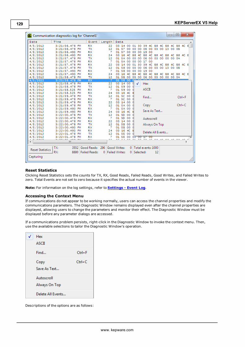
KEPServerEX V5 Help
Reset StatisticsClicking Reset Statistics sets the counts for TX, RX, Good Reads, Failed Reads, Good Writes, and Failed Writes tozero. Total Events are not set to zero because it specifies the actual number of events in the viewer.
Note: For information on the log settings, refer to Settings - Event Log.
Accessing the Context MenuIf communications do not appear to be working normally, users can access the channel properties and modify thecommunications parameters. The Diagnostic Window remains displayed even after the channel properties aredisplayed, allowing users to change the parameters and monitor their effect. The Diagnostic Window must bedisplayed before any parameter dialogs are accessed.
If a communications problem persists, right-click in the Diagnostic Window to invoke the context menu. Then,use the available selections to tailor the Diagnostic Window's operation.
Descriptions of the options are as follows:
www. kepware.com
129

KEPServerEX V5 Help
l Hex:When checked, the TX/RX details are formatted using hexadecimal notation.l ASCII:When checked, the TX/RX details are formatted using ASCII notation.l Find: This option invokes a dialog for entering a search string to be applied to the event details. For moreinformation, refer to Find.
l Copy: This option formats the protocol capture buffer's contents as text for easy "cut and paste" into anemail or fax message. This information helps Technical Support analyze and diagnose manycommunications issues.
l Save as Text File: This option saves all the events in the view to a specified file name (as text).l Autoscroll: This option scrolls the display as new events are received to ensure that the most recent oneis visible. It is turned off when users manually select an event (or when a selection is made by Find/FindNext).
l Always on Top: This option forces the Diagnostics Window to remain on the top of all other applicationwindows. This is the default setting.
l Delete All Events: This option clears the log being maintained by the Event Log and results in thedeletion of data.
FindThis dialog searches the Diagnostics View for key information transferred between the client and server.
Description of the parameter is as follows:
l Search all data for: This field specifies the search criteria.
Note:When an event or detail with the specified text is found, the line containing the text is highlighted. Toperform a Find Next operation (and look for the next occurrence of the specified text), press "F3". When the lastoccurrence is found, a message box is displayed indicating this condition. Users can change the search criteriaat any time by pressing "Ctrl+F".
www. kepware.com
130
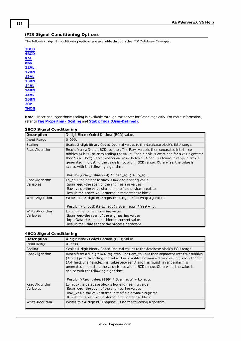
KEPServerEX V5 Help
iFIX Signal Conditioning OptionsThe following signal conditioning options are available through the iFIX Database Manager:
3BCD4BCD8AL8BN12AL12BN13AL13BN14AL14BN15AL15BN20PTNON
Note: Linear and logarithmic scaling is available through the server for Static tags only. For more information,refer to Tag Properties - Scaling and Static Tags (User-Defined).
3BCD Signal ConditioningDescription 3-digit Binary Coded Decimal (BCD) value.Input Range 0-999.Scaling Scales 3-digit Binary Coded Decimal values to the database block's EGU range.Read Algorithm Reads from a 3-digit BCD register. The Raw_value is then separated into three
nibbles (4 bits) prior to scaling the value. Each nibble is examined for a value greaterthan 9 (A-F hex). If a hexadecimal value between A and F is found, a range alarm isgenerated, indicating the value is not within BCD range. Otherwise, the value isscaled with the following algorithm:
Result=((Raw_value/999) * Span_egu) + Lo_egu.Read AlgorithmVariables
Lo_egu-the database block's low engineering value.Span_egu -the span of the engineering values.Raw_value-the value stored in the field device's register.Result-the scaled value stored in the database block.
Write Algorithm Writes to a 3-digit BCD register using the following algorithm:
Result=(((InputData-Lo_egu) / Span_egu) * 999 + .5.Write AlgorithmVariables
Lo_egu-the low engineering value.Span_egu-the span of the engineering values.InputData-the database block's current value.Result-the value sent to the process hardware.
4BCD Signal ConditioningDescription 4-digit Binary Coded Decimal (BCD) value.Input Range 0-9999.Scaling Scales 4-digit Binary Coded Decimal values to the database block's EGU range.Read Algorithm Reads from a 4-digit BCD register. The Raw_value is then separated into four nibbles
(4 bits) prior to scaling the value. Each nibble is examined for a value greater than 9(A-F hex). If a hexadecimal value between A and F is found, a range alarm isgenerated, indicating the value is not within BCD range. Otherwise, the value isscaled with the following algorithm:
Result=((Raw_value/9999) * Span_egu) + Lo_egu.Read AlgorithmVariables
Lo_egu-the database block's low engineering value.Span_egu -the span of the engineering values.Raw_value-the value stored in the field device's register.Result-the scaled value stored in the database block.
Write Algorithm Writes to a 4-digit BCD register using the following algorithm:
www. kepware.com
131

KEPServerEX V5 Help
Result=(((InputData-Lo_egu) / Span_egu) * 9999 + .5.Write AlgorithmVariables
Lo_egu-the low engineering value.Span_egu-the span of the engineering values.InputData-the database block's current value.Result-the value sent to the process hardware.
8AL Signal ConditioningDescription 8-bit binary number.Input Range 0-255.Scaling Scales 8-bit binary values to the database block's EGU range.Read Algorithm Reads from a 16-bit register using the same algorithm as 8BN, and returns a status
indicating whether the value is out of range and in an alarm state, or OK.
Result=((Raw_value/255) * Span_egu) + Lo_egu.Read AlgorithmVariables
Lo_egu-the database block's low engineering value.Span_egu -the span of the engineering values.Raw_value-the value stored in the field device's register.Result-the scaled value stored in the database block.
Write Algorithm Writes to a 16-bit register using the same algorithm as 8BN, and returns a statusindicating whether the value is out of range and in an alarm state, or OK.
Result=(((InputData-Lo_egu)/Span_egu) * 255) + .5.Write AlgorithmVariables
Lo_egu-the low engineering value.Span_egu-the span of the engineering values.InputData-the database block's current value.Result-the value sent to the process hardware.
8BN Signal ConditioningDescription 8-bit binary number.Input Range 0-255.Scaling Scales 8-bit binary values to the database block's EGU range. Ignores the most
significant byte.Read Algorithm Reads from a 16-bit register using the following algorithm:
Result =((Raw_value/255) * Span_egu) + Lo_egu.Read AlgorithmVariables
Lo_egu-the database block's low engineering value.Span_egu -the span of the engineering values.Raw_value-the value stored in the field device's register.Result-the scaled value stored in the database block.
Write Algorithm Writes to an 8-bit register using the following algorithm:
Result =(((InputData-Lo_egu)/Span_egu) * 255) + .5.Write AlgorithmVariables
Lo_egu-the low engineering value.Span_egu-the span of the engineering values.InputData-the database block's current value.Result-the value sent to the process hardware.
12AL Signal ConditioningDescription 12-bit binary number.Input Range 0-4095.Scaling Scales 12-bit binary values to the database block's EGU range.Read Algorithm Reads from a 16-bit register using the same algorithm as 12BN, and returns a status
indicating whether the value is out of range and in an alarm state, or OK.
Result=((Raw_value/4095) * Span_egu) + Lo_egu.Read AlgorithmVariables
Lo_egu-the database block's low engineering value.Span_egu -the span of the engineering values.Raw_value-the value stored in the field device's register.Result-the scaled value stored in the database block.
Write Algorithm Writes to a 16-bit register using the same algorithm as 12BN, and returns a statusindicating whether the value is out of range and in an alarm state, or OK.
www. kepware.com
132

KEPServerEX V5 Help
Result=(((InputData-Lo_egu)/Span_egu) * 4095) + .5.Write AlgorithmVariables
Lo_egu-the low engineering value.Span_egu-the span of the engineering values.InputData-the database block's current value.Result-the value sent to the process hardware.
12BN Signal ConditioningDescription 12-bit binary number.Input Range 0-4095.Scaling Scales 12-bit binary values to the database block's EGU range. Ignores the most
significant nibble (4-bits). Out of range value are treated as 12-bit values. Forexample, 4096 is treated as 0 because the four most significant bits are ignored.
Read Algorithm Reads from a 16-bit register using the following algorithm:
Result =((Raw_value/4095) * Span_egu) + Lo_egu.Read AlgorithmVariables
Lo_egu-the database block's low engineering value.Span_egu -the span of the engineering values.Raw_value-the value stored in the field device's register.Result-the scaled value stored in the database block.
Write Algorithm Writes to a 16-bit register using the following algorithm:
Result =(((InputData-Lo_egu)/Span_egu) * 4095) + .5.Write AlgorithmVariables
Lo_egu-the low engineering value.Span_egu-the span of the engineering values.InputData-the database block's current value.Result-the value sent to the process hardware.
13AL Signal ConditioningDescription 13-bit binary number.Input Range 0-8191.Scaling Scales 13-bit binary values to the database block's EGU range.Read Algorithm Reads from a 16-bit register using the same algorithm as 13BN, and returns a status
indicating whether the value is out of range and in an alarm state, or OK.
Result=((Raw_value/8191) * Span_egu) + Lo_egu.Read AlgorithmVariables
Lo_egu-the database block's low engineering value.Span_egu -the span of the engineering values.Raw_value-the value stored in the field device's register.Result-the scaled value stored in the database block.
Write Algorithm Writes to a 16-bit register using the same algorithm as 13BN, and returns a statusindicating whether the value is out of range and in an alarm state, or OK.
Result=(((InputData-Lo_egu)/Span_egu) * 8191) + .5.Write AlgorithmVariables
Lo_egu-the low engineering value.Span_egu-the span of the engineering values.InputData-the database block's current value.Result-the value sent to the process hardware.
13BN Signal ConditioningDescription 13-bit binary number.Input Range 0-8191.Scaling Scales 13-bit binary values to the database block's EGU range. Ignores the most
significant 3 bits.Read Algorithm Reads from a 16-bit register using the following algorithm:
Result =((Raw_value/8191) * Span_egu) + Lo_egu.Read AlgorithmVariables
Lo_egu-the database block's low engineering value.Span_egu -the span of the engineering values.Raw_value-the value stored in the field device's register.Result-the scaled value stored in the database block.
www. kepware.com
133

KEPServerEX V5 Help
Write Algorithm Writes to a 16-bit register using the following algorithm:
Result =(((InputData-Lo_egu)/Span_egu) * 8191) + .5.Write AlgorithmVariables
Lo_egu-the low engineering value.Span_egu-the span of the engineering values.InputData-the database block's current value.Result-the value sent to the process hardware.
14AL Signal ConditioningDescription 14-bit binary number.Input Range 0-16383.Scaling Scales 14-bit binary values to the database block's EGU range.Read Algorithm Reads from a 16-bit register using the same algorithm as 14BN, and returns a status
indicating whether the value is out of range and in an alarm state, or OK.
Result=((Raw_value/16383) * Span_egu) + Lo_egu.Read AlgorithmVariables
Lo_egu-the database block's low engineering value.Span_egu-the span of the engineering values.Raw_value-the value stored in the field device's register.Result-the scaled value stored in the database block.
Write Algorithm Writes to a 16-bit register using the same algorithm as 14BN, and returns a statusindicating whether the value is out of range and in an alarm state, or OK.
Result=(((InputData-Lo_egu)/Span_egu) * 16383) + .5.Write AlgorithmVariables
Lo_egu-the low engineering value.Span_egu-the span of the engineering values.InputData-the database block's current value.Result-the value sent to the process hardware.
14BN Signal ConditioningDescription 14-bit binary number.Input Range 0-16383.Scaling Scales 14-bit binary values to the database block's EGU range. Ignores the most
significant 2 bits.Read Algorithm Reads from a 16-bit register using the following algorithm:
Result=((Raw_value/16383) * Span_egu) + Lo_egu.Read AlgorithmVariables
Lo_egu-the database block's low engineering value.Span_egu-the span of the engineering values.Raw_value-the value stored in the field device's register.Result-the scaled value stored in the database block.
Write Algorithm Writes to a 16-bit register using the following algorithm:
Result=(((InputData-Lo_egu)/Span_egu) * 16383) + .5.Write AlgorithmVariables
Lo_egu-the low engineering value.Span_egu-the span of the engineering values.InputData-the database block's current value.Result-the value sent to the process hardware.
15AL Signal ConditioningDescription 15-bit binary number.Input Range 0-32767.Scaling Scales 15-bit binary values to the database block's EGU range.Read Algorithm Reads from a 16-bit register with alarming using the same algorithm as 15BN, and
returns a status indicating whether the value is out of range and in an alarm state, orOK.
Result=((Raw_value/32767) * Span_egu) + Lo_egu.Read AlgorithmVariables
Lo_egu-the database block's low engineering value.Span_egu -the span of the engineering values.Raw_value-the value stored in the field device's register.
www. kepware.com
134

KEPServerEX V5 Help
Result-the scaled value stored in the database block.Write Algorithm Writes to a 16-bit register with alarming using the same algorithm as 15BN, and
returns a status indicating whether the value is out of range and in an alarm state, orOK.
Result=(((InputData-Lo_egu)/Span_egu) * 32767) + .5.Write AlgorithmVariables
Lo_egu-the low engineering value.Span_egu-the span of the engineering values.InputData-the database block's current value.Result-the value sent to the process hardware.
15BN Signal ConditioningDescription 15-bit binary number.Input Range 0-32767.Scaling Scales 15-bit binary values to the database block's EGU range. Ignores the most
significant bit.Read Algorithm Reads from a 16-bit register using the following algorithm:
Result =((Raw_value/32767) * Span_egu) + Lo_egu.Read AlgorithmVariables
Lo_egu-the database block's low engineering value.Span_egu -the span of the engineering values.Raw_value-the value stored in the field device's register.Result-the scaled value stored in the database block.
Write Algorithm Writes to a 16-bit register using the following algorithm:
Result =(((InputData-Lo_egu)/Span_egu) * 32767) + .5.Write AlgorithmVariables
Lo_egu-the low engineering value.Span_egu-the span of the engineering values.InputData-the database block's current value.Result-the value sent to the process hardware.
20P Signal ConditioningDescription 6400 – 32000 clamp.Input Range 6400 – 32000.Scaling Scales binary values to the database block's EGU range. Clamps value to 6400 –
32000 range.Read Algorithm Reads from a 16-bit register using the following algorithm:
Result =(((Raw_value-6400)/25600) * Span_egu) + Lo_egu.Read AlgorithmVariables
Lo_egu-the database block's low engineering value.Span_egu -the span of the engineering values.Raw_value-the value stored in the field device's register.Result-the scaled value stored in the database block.
Write Algorithm Writes to a 16-bit register using the following algorithm:
Result =(((InputData-Lo_egu)/Span_egu) * 25600) + 6400.5.Write AlgorithmVariables
Lo_egu-the low engineering value.Span_egu-the span of the engineering values.InputData-the database block's current value.Result-the value sent to the process hardware.
TNON Signal ConditioningDescription 0 – 32000 Clamp.Input Range 0 – 32000.Scaling Scales binary values to the database block's EGU range. Clamps value to 0 – 32000
range.Read Algorithm Reads from a 16-bit register using the following algorithm:
Result =((Raw_value/32000) * Span_egu) + Lo_egu.Read AlgorithmVariables
Lo_egu-the database block's low engineering value.Span_egu -the span of the engineering values.
www. kepware.com
135
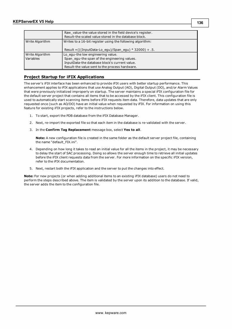
KEPServerEX V5 Help
Raw_value-the value stored in the field device's register.Result-the scaled value stored in the database block.
Write Algorithm Writes to a 16-bit register using the following algorithm:
Result =(((InputData-Lo_egu)/Span_egu) * 32000) + .5.Write AlgorithmVariables
Lo_egu-the low engineering value.Span_egu-the span of the engineering values.InputData-the database block's current value.Result-the value sent to the process hardware.
Project Startup for iFIX ApplicationsThe server's iFIX interface has been enhanced to provide iFIX users with better startup performance. Thisenhancement applies to iFIX applications that use Analog Output (AO), Digital Output (DO), and/or Alarm Valuesthat were previously initialized improperly on startup. The server maintains a special iFIX configuration file forthe default server project that contains all items that to be accessed by the iFIX client. This configuration file isused to automatically start scanning items before iFIX requests item data. Therefore, data updates that are onlyrequested once (such as AO/DO) have an initial value when requested by iFIX. For information on using thisfeature for existing iFIX projects, refer to the instructions below.
1. To start, export the PDB database from the iFIX Database Manager.
2. Next, re-import the exported file so that each item in the database is re-validated with the server.
3. In the Confirm Tag Replacement message box, select Yes to all.
Note: A new configuration file is created in the same folder as the default server project file, containingthe name "default_FIX.ini".
4. Depending on how long it takes to read an initial value for all the items in the project, it may be necessaryto delay the start of SAC processing. Doing so allows the server enough time to retrieve all initial updatesbefore the iFIX client requests data from the server. For more information on the specific iFIX version,refer to the iFIX documentation.
5. Next, restart both the iFIX application and the server to put the changes into effect.
Note: For new projects (or when adding additional items to an existing iFIX database) users do not need toperform the steps described above. The item is validated by the server upon its addition to the database. If valid,the server adds the item to the configuration file.
www. kepware.com
136
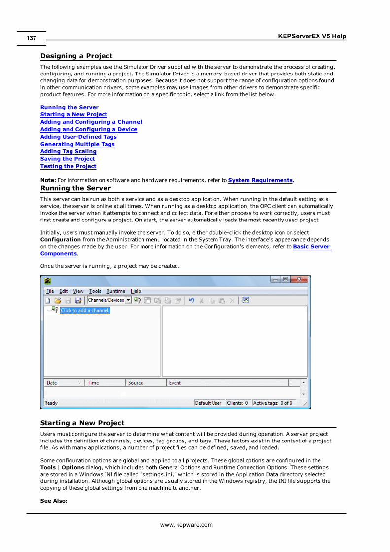
KEPServerEX V5 Help
Designing a ProjectThe following examples use the Simulator Driver supplied with the server to demonstrate the process of creating,configuring, and running a project. The Simulator Driver is a memory-based driver that provides both static andchanging data for demonstration purposes. Because it does not support the range of configuration options foundin other communication drivers, some examples may use images from other drivers to demonstrate specificproduct features. For more information on a specific topic, select a link from the list below.
Running the ServerStarting a New ProjectAdding and Configuring a ChannelAdding and Configuring a DeviceAdding User-Defined TagsGenerating Multiple TagsAdding Tag ScalingSaving the ProjectTesting the Project
Note: For information on software and hardware requirements, refer to System Requirements.Running the ServerThis server can be run as both a service and as a desktop application. When running in the default setting as aservice, the server is online at all times. When running as a desktop application, the OPC client can automaticallyinvoke the server when it attempts to connect and collect data. For either process to work correctly, users mustfirst create and configure a project. On start, the server automatically loads the most recently used project.
Initially, users must manually invoke the server. To do so, either double-click the desktop icon or selectConfiguration from the Administration menu located in the System Tray. The interface's appearance dependson the changes made by the user. For more information on the Configuration's elements, refer to Basic ServerComponents.
Once the server is running, a project may be created.
Starting a New ProjectUsers must configure the server to determine what content will be provided during operation. A server projectincludes the definition of channels, devices, tag groups, and tags. These factors exist in the context of a projectfile. As with many applications, a number of project files can be defined, saved, and loaded.
Some configuration options are global and applied to all projects. These global options are configured in theTools | Options dialog, which includes both General Options and Runtime Connection Options. These settingsare stored in a Windows INI file called "settings.ini," which is stored in the Application Data directory selectedduring installation. Although global options are usually stored in the Windows registry, the INI file supports thecopying of these global settings from one machine to another.
See Also:
www. kepware.com
137

KEPServerEX V5 Help
Options - General
Adding and Configuring a ChannelWhen creating a new project, users must first determine the communications driver that is required by theapplication: this is referred to as a channel in the server. A number of channels can be defined within a singleproject, depending on the driver or drivers installed. For more information, refer to the instructions below.
1. To start, add a new channel to the project by clicking Edit | Channels/Devices | New Channel.Alternatively, click theNew Channel icon on the toolbar.
2. In the channel wizard, leave the channel name at its default setting "Channel1". Then, clickNext.
3. In Device Driver, select the communications driver to be applied to the channel. Then, clickNext. Inthis example, the Simulator Driver is used.
4. For the Simulator Driver, the next dialog is Channel Summary. Other devices may have additionalchannel wizard pages that allow the configuration of other parameters (such as communications port,baud rate, and parity). For more information, refer to Channel Properties - Communications.
5. Once complete, click Finish.
www. kepware.com
138

KEPServerEX V5 Help
Important: A small red "x" should be visible below the channel icon. This denotes that the channel does notcontain a valid configuration (because no devices have been added yet).
See Also:How to... Optimize the Server ProjectServer Summary Information
Adding and Configuring a DeviceOnce a channel has been defined, a device can be added. The device identifies a communication link's physicalnode or station, and can be thought of as a way to frame the connection's definition to a specific point of interestin the application. In this respect, a device is the correct term for describing the connection to a database object.As such, "device" refers to a specific device on a network, support multiple device nodes, and allows users tosimulate networked devices.
Note: In this example, the Simulator Driver is used. The number of device wizard dialogs depends on the driver.
1. To start, select the channel to which the device will be added. Then, click Edit | Channels/Devices |New Device. Alternatively, click the Add Device icon on the toolbar.
www. kepware.com
139
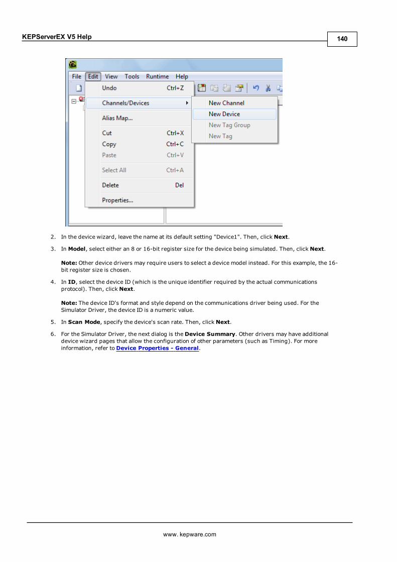
KEPServerEX V5 Help
2. In the device wizard, leave the name at its default setting "Device1". Then, clickNext.
3. In Model, select either an 8 or 16-bit register size for the device being simulated. Then, clickNext.
Note: Other device drivers may require users to select a device model instead. For this example, the 16-bit register size is chosen.
4. In ID, select the device ID (which is the unique identifier required by the actual communicationsprotocol). Then, clickNext.
Note: The device ID's format and style depend on the communications driver being used. For theSimulator Driver, the device ID is a numeric value.
5. In Scan Mode, specify the device's scan rate. Then, clickNext.
6. For the Simulator Driver, the next dialog is theDevice Summary. Other drivers may have additionaldevice wizard pages that allow the configuration of other parameters (such as Timing). For moreinformation, refer toDevice Properties - General.
www. kepware.com
140

KEPServerEX V5 Help
7. Once complete, click Finish.
Note: With the server's online full-time mode of operation, the server can start providing OPC data immediately.At this point, however, the configuration can potentially be lost because the project hasn't been saved. Beforesaving, users can add tags to the server. For more information, refer to Adding User-Defined Tags.
Adding User-Defined TagsThe server can get data from a device to the client application in two ways. The most common method requiresthat users define a set of tags in the server project and then use the name previously assigned to each tag as theitem of each link between the client and the server. This method makes all user-defined tags available forbrowsing within OPC clients.
Tips: User-defined tags support scaling. For more information, refer to Adding Tag Scaling. Some situations support browsing for and selecting multiple tags. For more information, refer to Browsingfor Tags.
1. To start, select a device name from the channel/device tree hierarchy in the server. In this example, theselected device is "Device1".
2. Next, click Edit | Channels/Devices | New Tag. Alternatively, right-click on the device and select AddTag.
www. kepware.com
141

KEPServerEX V5 Help
3. In Tag Properties - General, edit the parameters to match the following:
l Tag Name: MyFirstTag
l Address: R000
l Description (Optional):My First Simulator Tag
l Data Type:Word
l Client Access: read/write
l Scan Rate: 100 milliseconds. This parameter does not apply to OPC tags.
Note: For more information, refer to Tag Properties - General.
4. If necessary, useHints to determine the driver's correct settings. To invoke Hints, click on the questionmark icon in Tag Properties.
www. kepware.com
142
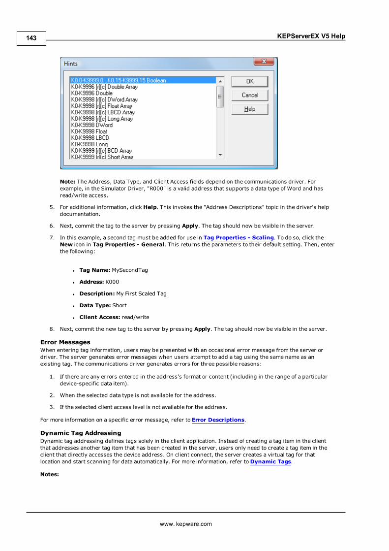
KEPServerEX V5 Help
Note: The Address, Data Type, and Client Access fields depend on the communications driver. Forexample, in the Simulator Driver, "R000" is a valid address that supports a data type of Word and hasread/write access.
5. For additional information, click Help. This invokes the "Address Descriptions" topic in the driver's helpdocumentation.
6. Next, commit the tag to the server by pressing Apply. The tag should now be visible in the server.
7. In this example, a second tag must be added for use in Tag Properties - Scaling. To do so, click theNew icon in Tag Properties - General. This returns the parameters to their default setting. Then, enterthe following:
l Tag Name: MySecondTag
l Address: K000
l Description:My First Scaled Tag
l Data Type: Short
l Client Access: read/write
8. Next, commit the new tag to the server by pressing Apply. The tag should now be visible in the server.
Error MessagesWhen entering tag information, users may be presented with an occasional error message from the server ordriver. The server generates error messages when users attempt to add a tag using the same name as anexisting tag. The communications driver generates errors for three possible reasons:
1. If there are any errors entered in the address's format or content (including in the range of a particulardevice-specific data item).
2. When the selected data type is not available for the address.
3. If the selected client access level is not available for the address.
For more information on a specific error message, refer to Error Descriptions.
Dynamic Tag AddressingDynamic tag addressing defines tags solely in the client application. Instead of creating a tag item in the clientthat addresses another tag item that has been created in the server, users only need to create a tag item in theclient that directly accesses the device address. On client connect, the server creates a virtual tag for thatlocation and start scanning for data automatically. For more information, refer toDynamic Tags.
Notes:
www. kepware.com
143
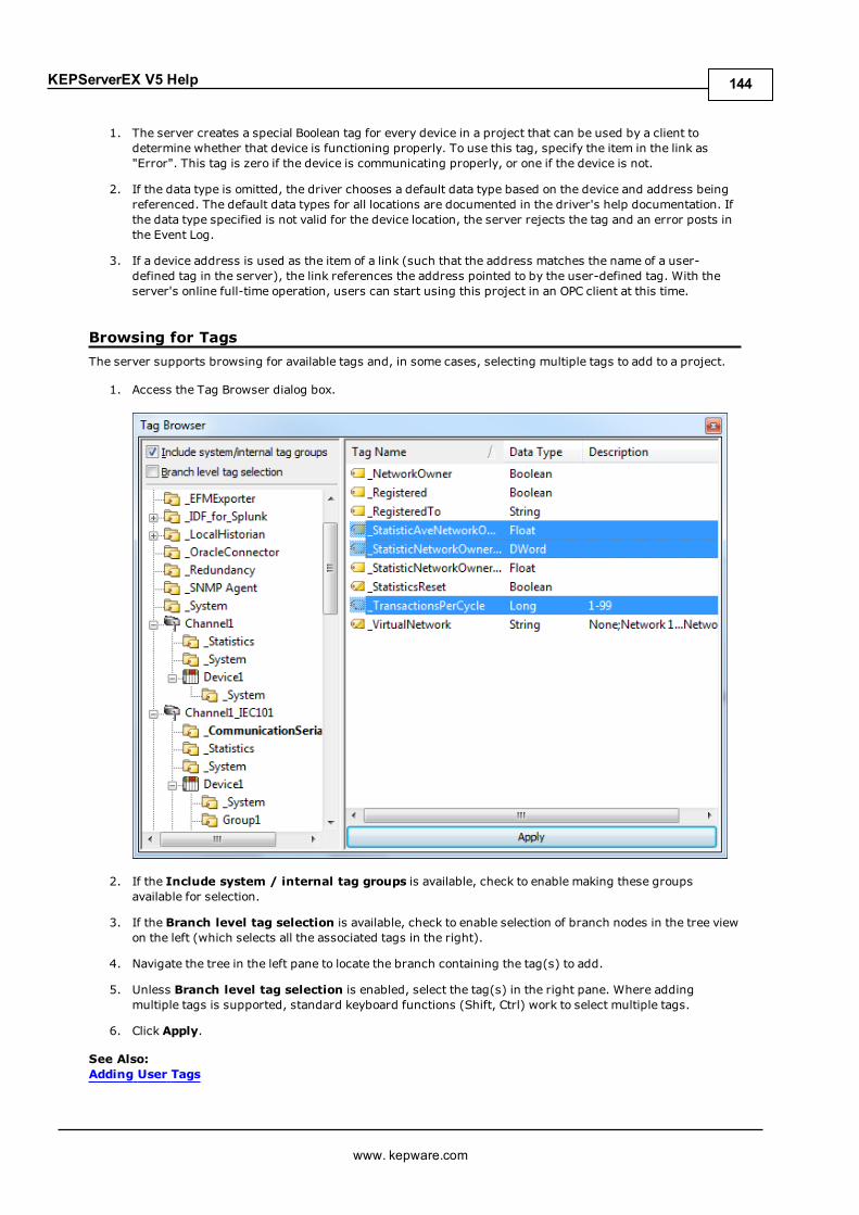
KEPServerEX V5 Help
1. The server creates a special Boolean tag for every device in a project that can be used by a client todetermine whether that device is functioning properly. To use this tag, specify the item in the link as"Error". This tag is zero if the device is communicating properly, or one if the device is not.
2. If the data type is omitted, the driver chooses a default data type based on the device and address beingreferenced. The default data types for all locations are documented in the driver's help documentation. Ifthe data type specified is not valid for the device location, the server rejects the tag and an error posts inthe Event Log.
3. If a device address is used as the item of a link (such that the address matches the name of a user-defined tag in the server), the link references the address pointed to by the user-defined tag. With theserver's online full-time operation, users can start using this project in an OPC client at this time.
Browsing for TagsThe server supports browsing for available tags and, in some cases, selecting multiple tags to add to a project.
1. Access the Tag Browser dialog box.
2. If the Include system / internal tag groups is available, check to enable making these groupsavailable for selection.
3. If the Branch level tag selection is available, check to enable selection of branch nodes in the tree viewon the left (which selects all the associated tags in the right).
4. Navigate the tree in the left pane to locate the branch containing the tag(s) to add.
5. Unless Branch level tag selection is enabled, select the tag(s) in the right pane. Where addingmultiple tags is supported, standard keyboard functions (Shift, Ctrl) work to select multiple tags.
6. Click Apply.
See Also:Adding User Tags
www. kepware.com
144

KEPServerEX V5 Help
Generating Multiple TagsThe Multiple Tag Generation Tool dynamically creates tags using user-defined driver nomenclature. Forinformation on using the tool, refer to the instructions below. For more information on its dialogs and parameters,refer toMultiple Tag Generation.
1. To start, select a device and then click Edit | Channels/Devices | New Tag. Alternatively, right-click ona device and then select New Tag.
2. In Tag Properties, select theMultiple Tag Generation icon (located to the bottom-right of theIdentification parameters).
3. In Multiple Tag Generation, first define the tag name. Then, configure theData Propertiesparameters as desired.
www. kepware.com
145

KEPServerEX V5 Help
4. Next, click Add Static Text. In this dialog, enter the text as desired. Once finished, press OK.
5. Next, click Add Numeric Range. In this dialog, enter the base system, range, and increment. Oncefinished, press OK.
www. kepware.com
146
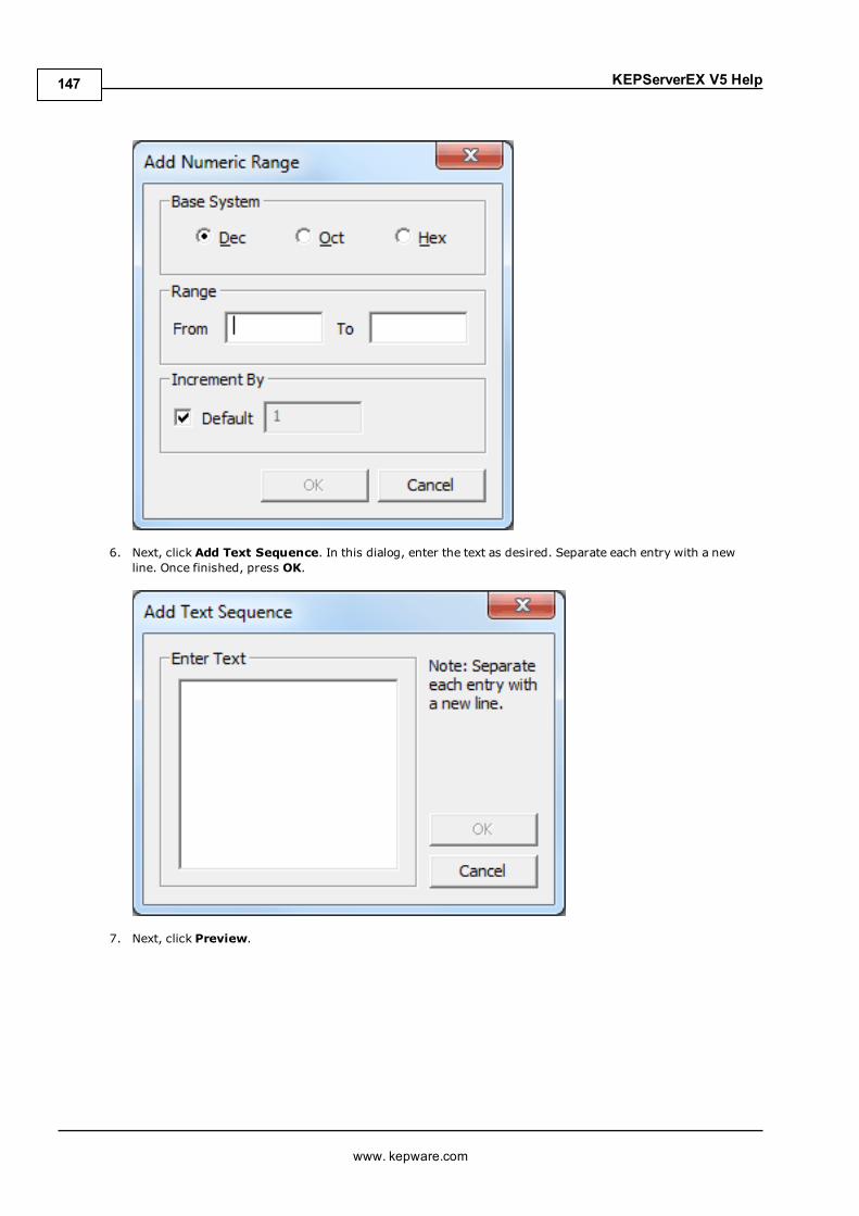
KEPServerEX V5 Help
6. Next, click Add Text Sequence. In this dialog, enter the text as desired. Separate each entry with a newline. Once finished, press OK.
7. Next, click Preview.
www. kepware.com
147

KEPServerEX V5 Help
Note: Valid tags are displayed with a green checkmark. Invalid tags are displayed with a red x.
8. To add the tags as a group, check Add as Group.
9. To change a tag's name or starting value, select Tag Name. Once finished, clickOK.
10. To generate the tags, click Generate. If the generation is successful, users return to the Multiple TagGeneration dialog.
11. Click Close. Then, clickOK.
Note: The generated tags should now be visible in the tag display window.
www. kepware.com
148

KEPServerEX V5 Help
See Also:Multiple Tag Generation
Adding Tag ScalingUsers have the option of applying tag scaling when creating a new tag in the server. This allows raw data fromthe device to be scaled to an appropriate range for the application. There are two types of scaling: Linear andSquare Root. For more information, refer to Tag Properties - Scaling.
Note: The image below uses the second tag created in Adding User-Defined Tags.
1. To start, open the tag's Tag Properties.
2. Next, open the Scaling tab and select Linear.
3. In Raw Value Range, specify the expected data range from the device. The scaled data type also allowsusers to specify how the resulting scaled value is presented to the OPC client application.
4. In Scaled Value Range, specify the desired range for the resulting value in engineering units. Applyingthe high and low clamps ensures that the output stays within the configured limits. If the raw dataexceeds the range set by the raw value High and Low, it forces the scaled value beyond the range that hasbeen entered for the scaled value. The clamps prevent this from occurring.
www. kepware.com
149

KEPServerEX V5 Help
5. In Units, specify a string to the OPC client that describes the format or unit for the resulting engineeringvalue. To use the Units field, an OPC client that can access the Data Access 2.0 tag properties data isrequired. If the client does not support these features, there is no need to configure this field.
6. Once the data has been entered as shown above, clickOK.
Saving the ProjectThere should now be a project configured with two user-defined tags that are ready to be saved. How the projectis saved depends on whether the project is a Runtime project or an offline project.
l When editing a Runtime project, the server's online full-time operation allows immediate access to tagsfrom an OPC client once it has been saved to disk. Because the changes are made to the actual project,users can save by clicking File | Save. Users can overwrite the existing project or save the edits as a newproject, and are also given the option of loading the new project as the default Runtime project.
www. kepware.com
150
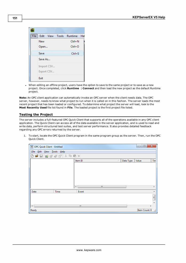
KEPServerEX V5 Help
l When editing an offline project, users have the option to save to the same project or to save as a newproject. Once completed, click Runtime | Connect and then load the new project as the default Runtimeproject.
Note: An OPC client application can automatically invoke an OPC server when the client needs data. The OPCserver, however, needs to know what project to run when it is called on in this fashion. The server loads the mostrecent project that has been loaded or configured. To determine what project the server will load, look to theMost Recently Used file list found in File. The loaded project is the first project file listed.
Testing the ProjectThe server includes a full-featured OPC Quick Client that supports all of the operations available in any OPC clientapplication. The Quick Client can access all of the data available in the server application, and is used to read andwrite data, perform structured test suites, and test server performance. It also provides detailed feedbackregarding any OPC errors returned by the server.
1. To start, locate the OPC Quick Client program in the same program group as the server. Then, run the OPCQuick Client.
www. kepware.com
151

KEPServerEX V5 Help
2. Next, establish a connection by clicking Edit | New Server Connection.
3. In Server Properties, make connections with an OPC server either locally or remotely via DCOM. Bydefault, this dialog is pre-configured with the server's Prog ID (which is used by OPC clients to referencea specific OPC server).
www. kepware.com
152
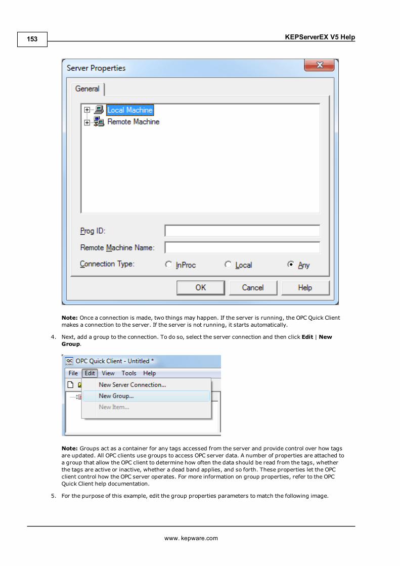
KEPServerEX V5 Help
Note: Once a connection is made, two things may happen. If the server is running, the OPC Quick Clientmakes a connection to the server. If the server is not running, it starts automatically.
4. Next, add a group to the connection. To do so, select the server connection and then click Edit | NewGroup.
Note: Groups act as a container for any tags accessed from the server and provide control over how tagsare updated. All OPC clients use groups to access OPC server data. A number of properties are attached toa group that allow the OPC client to determine how often the data should be read from the tags, whetherthe tags are active or inactive, whether a dead band applies, and so forth. These properties let the OPCclient control how the OPC server operates. For more information on group properties, refer to the OPCQuick Client help documentation.
5. For the purpose of this example, edit the group properties parameters to match the following image.
www. kepware.com
153
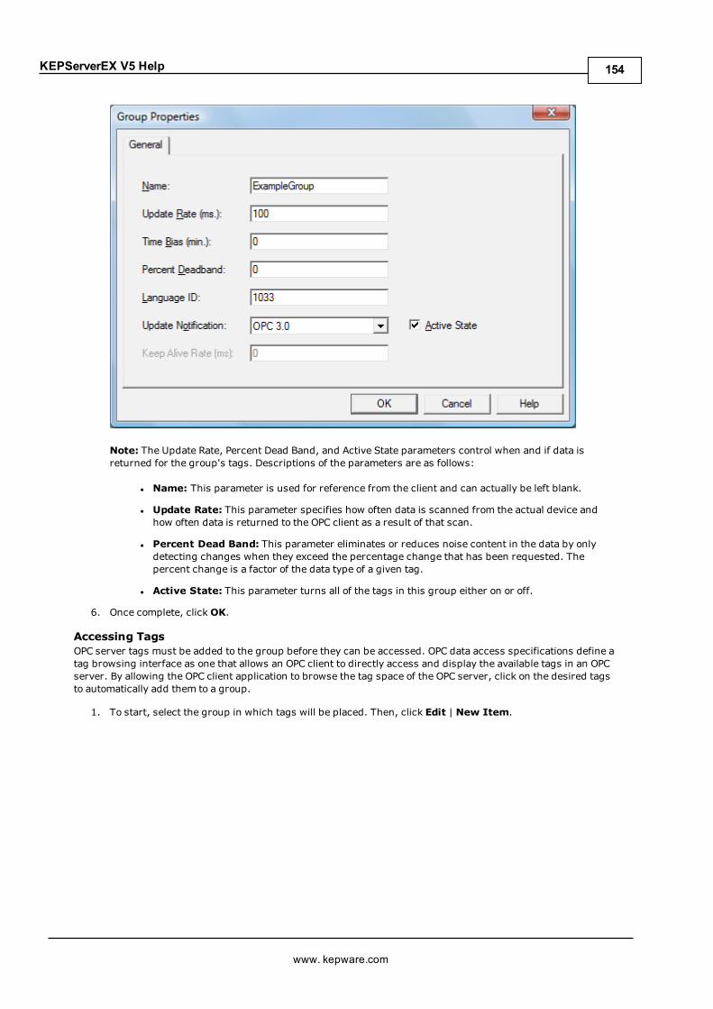
KEPServerEX V5 Help
Note: The Update Rate, Percent Dead Band, and Active State parameters control when and if data isreturned for the group's tags. Descriptions of the parameters are as follows:
l Name: This parameter is used for reference from the client and can actually be left blank.
l Update Rate: This parameter specifies how often data is scanned from the actual device andhow often data is returned to the OPC client as a result of that scan.
l Percent Dead Band: This parameter eliminates or reduces noise content in the data by onlydetecting changes when they exceed the percentage change that has been requested. Thepercent change is a factor of the data type of a given tag.
l Active State: This parameter turns all of the tags in this group either on or off.
6. Once complete, clickOK.
Accessing TagsOPC server tags must be added to the group before they can be accessed. OPC data access specifications define atag browsing interface as one that allows an OPC client to directly access and display the available tags in an OPCserver. By allowing the OPC client application to browse the tag space of the OPC server, click on the desired tagsto automatically add them to a group.
1. To start, select the group in which tags will be placed. Then, click Edit | New Item.
www. kepware.com
154
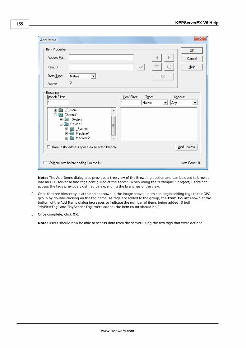
KEPServerEX V5 Help
Note: The Add Items dialog also provides a tree view of the Browsing section and can be used to browseinto an OPC server to find tags configured at the server. When using the "Example1" project, users canaccess the tags previously defined by expanding the branches of the view.
2. Once the tree hierarchy is at the point shown in the image above, users can begin adding tags to the OPCgroup by double-clicking on the tag name. As tags are added to the group, the Item Count shown at thebottom of the Add Items dialog increases to indicate the number of items being added. If both"MyFirstTag" and "MySecondTag" were added, the item count should be 2.
3. Once complete, clickOK.
Note: Users should now be able to access data from the server using the two tags that were defined.
www. kepware.com
155

KEPServerEX V5 Help
Note: The first tag, "MyFirstTag," should contain a changing value. The second tag should be zero at thispoint. If users only needed to test the reading of an OPC item, they are now finished. If, however, usersdesired to change an OPC item, they can use one of the write methods to send new data to the OPC item.
Writing Data to the OPC ServerThe OPC Quick Client supports twomethods for writing data to an OPC server: Synchronous Writes andAsynchronous Writes. Synchronous writes perform a write operation on the OPC server and wait for it tocomplete. Asynchronous writes perform a write on the OPC server but do not wait for the write to complete. Eithermethod can be chosen when writing data to an OPC item: the different write methods are more of a factor in OPCclient application design.
1. To start, first select the item. Then, right-click and select Synchronous or Asynchronous Writes. Forthe purpose of this example, right-click on "MyFirstTag" and select Asynchronous Write.
Note: Although the Asynchronous 2.0 Write dialog is displayed, the value continues to update.
2. To enter a new value for this item, clickWrite Value and then enter a different value.
3. Once finished, click Apply to write the data. This allows users to continue writing new values, whereasclicking OK writes the new value and closes the dialog.
4. Once complete, clickOK.
Note: If no new data has been entered, clicking OK does not send data to the server.
Conclusion
www. kepware.com
156

KEPServerEX V5 Help
At this point, all of the basic steps involved in building and testing an OPC project have been discussed. Users areencouraged to continue testing various features of the server and the OPC Quick Client for greater understandingand comprehension. For more information on the OPC Quick Client, refer to its help documentation.
Users can now begin developing the OPC application. If using Visual Basic, refer to the supplied exampleprojects. These two projects provide both a simple and complex example of how OPC technology can be useddirectly in Visual Basic applications.
New Channel - IdentificationThis server supports the use of simultaneous multiple communications drivers. Each protocol or driver used in aproject is called a channel, which refers to a specific communications driver. A server project can consist ofmany channels, each with either unique communications drivers or with the same. A channel acts as the basicbuilding block of an OPC link. Its properties control parameters such as communications port, baud rate andparity.
In a server project, each Channel Namemust be unique and can be up to 256 characters long. Althoughdescriptive names are usually a good idea, some OPC client applications may have a limited display window forbrowsing an OPC server's tag space. For information on reserved characters, refer toHow To... Properly Namea Channel, Device, Tag, and Tag Group.
Note: The channel name entered is part of the OPC browser information.
New Channel - Device DriverAfter a name has been entered for the new channel, a communications driver must be selected from the "Devicedriver:" drop-down list. The drop-down list's contents depend on the communications drivers currently installedon the PC. The list contains the drivers available for use in the server project.
www. kepware.com
157

KEPServerEX V5 Help
Since the server supports the use of simultaneous multiple communications drivers, users can add a number ofchannels to the project. It is not necessary to select a different communications driver for each channel. Many ofthe communications drivers available for the server support operation on either multiple communications ports oracross multiple network connections. If the driver chosen does not support multiple channels (or if the number ofsupported channels has been exceeded) the driver displays a dialog stating so.
Another server feature is the ability to run channel diagnostics. To make diagnostic information available to theOPC application, select the Enable Diagnostics check box. When diagnostic functions are enabled, Diagnostictags are available for use within client applications. A diagnostic window is available when this feature is enabled.For more information, refer toOPC Diagnostics Viewer.
New Channel - CommunicationsAfter a device driver has been selected, users must configure its communications. Because the server supportsseveral mediums for communications, the Communications dialog's format varies depending on the driver'srequirements. For more information on the available settings, refer to Channel Properties - Communications.
Note: This dialog is only available to serial drivers.
www. kepware.com
158

KEPServerEX V5 Help
Note: The dialog's additional options allow users to select and use dial-up modem support or EthernetEncapsulation for connecting to devices via serial to Ethernet terminal servers. For more information, refer toUsing a Modem in the Server Project and Device Properties - Ethernet Encapsulation.
New Channel - Modem Auto DialWhen the connection type is set to Modem, users are prompted to specify a phone number that can be dialedwhen establishing a connection to the channel. This ensures that a phone number is supplied in support of ashared connection. Users not utilizing shared connections can leave this parameter blank; however, if one isprovided, it is listed as the first item in the phonebook. For more information, refer toModem Auto-Dial.
Note: This dialog is only available to serial drivers.
www. kepware.com
159

KEPServerEX V5 Help
See Also:Phonebook TagsChannel Properties - Communications
New Channel - Connection BehaviorWhen the connection type is set to COM Port or modem, users can configure additional connection behaviors. Formore information, refer to Channel Properties - Communications.
Note: This dialog is only available to serial drivers.
www. kepware.com
160
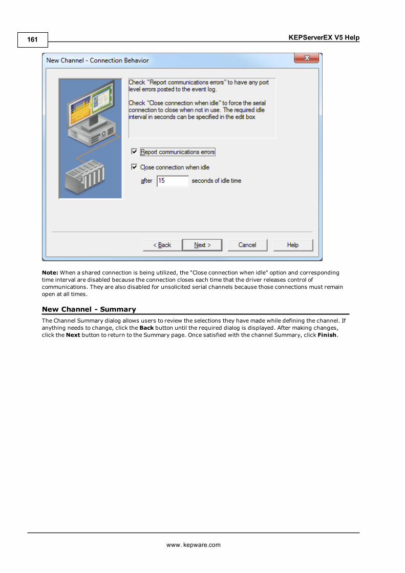
KEPServerEX V5 Help
Note:When a shared connection is being utilized, the "Close connection when idle" option and correspondingtime interval are disabled because the connection closes each time that the driver releases control ofcommunications. They are also disabled for unsolicited serial channels because those connections must remainopen at all times.
New Channel - SummaryThe Channel Summary dialog allows users to review the selections they have made while defining the channel. Ifanything needs to change, click the Back button until the required dialog is displayed. After making changes,click theNext button to return to the Summary page. Once satisfied with the channel Summary, click Finish.
www. kepware.com
161

KEPServerEX V5 Help
New Device - NameA device name can be the same from one channel to the next; however, each device under a channel must have aunique name. The device name is a user-defined logical name for the device that can be up to 256 characterslong. While long descriptive names are generally good, some OPC client applications may have a limited displaywindow when browsing the tag space of an OPC server. For information on reserved characters, refer toHowTo... Properly Name a Channel, Device, Tag, and Tag Group.
Note: The device name and channel name are part of the browse tree information.
www. kepware.com
162

KEPServerEX V5 Help
Note: Within an OPC client, the combination of channel name and device name would appear as"ChannelName.DeviceName".
New Device - ModelThe model parameter is used to select the device model associated with the device ID. The model selection drop-down menu contents vary depending on the chosen communication driver. If a driver does not support modelselection, this option is unavailable. If the communication driver does support multiple models, users shouldmatch the model selection to the physical device. If the device being used is not represented in the model drop-down list, select a model that conforms closest to the target device. This can be determined from the specificdriver's help documentation.
Note: Some drivers support an Open model, which allows users to communicate without knowing the targetdevice's specific details.
Note:With the server's online full-time operation, these parameters can be changes at any time. If thecommunications driver supports multiple device models, the model selection can only be changed if there arecurrently no client applications connected to the device. Since the device is being added at this time, any modelcan be selected. Utilize the User Manager to restrict access rights to server features and prevent operators fromchanging parameters.
New Device - IDThe device ID parameter is used to specify a device's driver-specific station or node. The type of ID entereddepends on the communication driver being used. For example, many communication drivers use a numericvalue. As shown in the image below, when a driver supports aNumeric ID, the menu option allows users toenter a numeric value. The numeric value's format can be changed to suit the needs of either the application orthe communication driver's characteristics. The format is set by the driver by default. Possible formats includeDecimal, Octal and Hexadecimal.
www. kepware.com
163
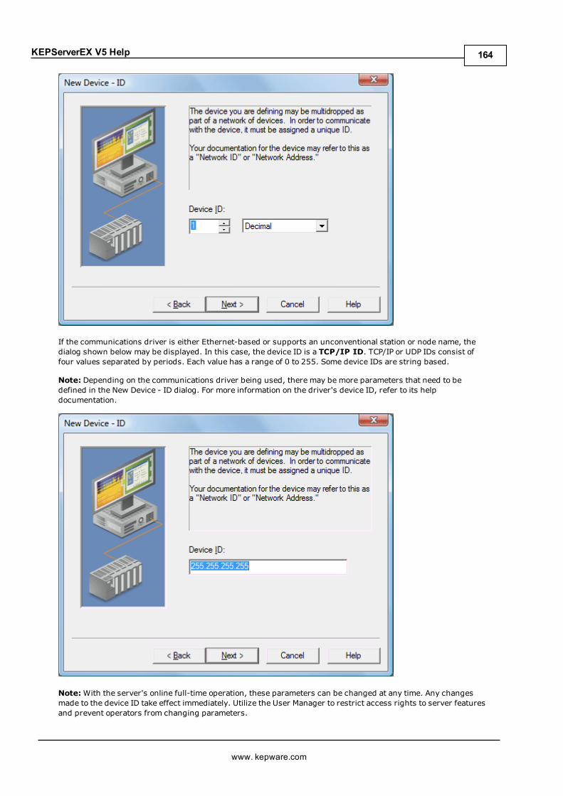
KEPServerEX V5 Help
If the communications driver is either Ethernet-based or supports an unconventional station or node name, thedialog shown below may be displayed. In this case, the device ID is a TCP/IP ID. TCP/IP or UDP IDs consist offour values separated by periods. Each value has a range of 0 to 255. Some device IDs are string based.
Note: Depending on the communications driver being used, there may be more parameters that need to bedefined in the New Device - ID dialog. For more information on the driver's device ID, refer to its helpdocumentation.
Note:With the server's online full-time operation, these parameters can be changed at any time. Any changesmade to the device ID take effect immediately. Utilize the User Manager to restrict access rights to server featuresand prevent operators from changing parameters.
www. kepware.com
164

KEPServerEX V5 Help
New Device - Scan ModeThe Scan Mode parameters determine the device's scan rate. Users can specify whether to use the scan rate thatis requested by the client, to define a maximum scan rate that can be used, or to force all tags to be scanned atthe specified rate. The default setting is Respect client specified scan rate.
See Also:Device Properties - Scan Mode
New Device - TimingDevice Timing parameters allow a driver's response to error conditions to be tailored to the application's needs.The environment in which the application runs may require changes to the timing parameters. Factors such aselectrically generated noise, modem delays and bad physical connections can all influence how many errors ortimeouts a communications driver may encounter. The timing parameters are specific to each configured device.
www. kepware.com
165

KEPServerEX V5 Help
Note: For most projects, the default timeout settings work well. If users find that the project takes too long totime out a device or that there are too many timeouts, they can adjust the settings to improve performance.
New Device - SummaryThe device Summary page allows users to review the selections that have been made for the device. To make achange, click the Back button until the required dialog is displayed. After making changes, users can click theNext button to return to the Summary page. Once satisfied with the device Summary, click Finish.
www. kepware.com
166

KEPServerEX V5 Help
How Do I...For more information, select a link from the list below.
Allow Desktop InteractionsCreate and Use an AliasOptimize the Server ProjectProcess Array DataProperly Name a Channel, Device, Tag, and Tag GroupResolve Comm Issues When the DNS/DHCP Device Connected to the Server is Power CycledSelect the Correct Network CableUse an Alias to Optimize a ProjectUse DDE with the ServerUse Dynamic Tag AddressingUse Ethernet EncapsulationUse Net DDE Across a NetworkWork with Non-Normalized Floating Point Values
How To... Allow Desktop InteractionsSome communication interfaces require the server to interact with the desktop. For example, WindowsMessaging Layer is used by DDE and FastDDE. It is important that the operating system be taken intoconsideration when choosing how to communicate with the desktop.
Windows Vista, Windows Server 2008, and Later Operating SystemsIn Windows Vista, Windows Server 2008, and later operating systems, services run in an isolated session that isinaccessible to users logged on to the console. These operating systems require that the process mode be set toInteractive. This allows the Runtime to run in the same user account as the current user. For information onchanging the process mode, refer to Settings - Runtime Process.
Windows XP, Windows Server 2003, and Earlier Operating SystemsIn Windows XP, Windows Server 2003, and earlier operating systems, the process mode can remain set as aSystem Service. The runtime service, however, must be allowed to interact with the desktop. This is thepreferred mode of operation since a user is not required to be logged on to the console for the server to start. Forinformation on allowing a service to interact with the desktop, follow the instructions below.
Note: These service settings only apply when the server is running in Service Mode.
1. To start, launch the Services snap-in (which is part of theMicrosoft Management Console). To do so,click Start | Run.
2. Type "services.msc" and clickOK. Then, locate the server by its name in the list of services. Open itscontext menu and select Properties.
3. Next, open the Log On tab and check Allow service to interact with desktop. Then, click Apply.
4. ClickOK to exit.
5. Next, locate the Administration icon. Open its context menu and select Stop Runtime Service.
6. Then, re-open the context menu and select Start Runtime Service.
See Also:Accessing the Administration Menu
www. kepware.com
167
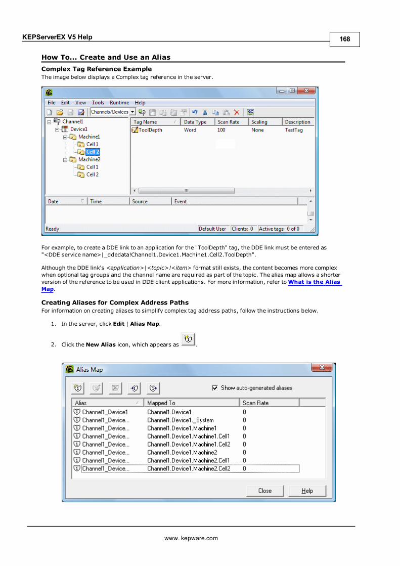
KEPServerEX V5 Help
How To... Create and Use an AliasComplex Tag Reference ExampleThe image below displays a Complex tag reference in the server.
For example, to create a DDE link to an application for the "ToolDepth" tag, the DDE link must be entered as"<DDE service name>|_ddedata!Channel1.Device1.Machine1.Cell2.ToolDepth".
Although the DDE link's <application>|<topic>!<item> format still exists, the content becomes more complexwhen optional tag groups and the channel name are required as part of the topic. The alias map allows a shorterversion of the reference to be used in DDE client applications. For more information, refer toWhat is the AliasMap.
Creating Aliases for Complex Address PathsFor information on creating aliases to simplify complex tag address paths, follow the instructions below.
1. In the server, click Edit | Alias Map.
2. Click theNew Alias icon, which appears as .
www. kepware.com
168

KEPServerEX V5 Help
3. Next, browse to the group or device that contains the item to be referenced.
4. Enter an alias name to represent the complex tag reference. This alias name can now be used in the clientapplication to address the tag found in the server. For information on reserved characters, refer toHowTo... Properly Name a Channel, Device, Tag, and Tag Group.
5. The complex topic and item name "_ddedata! Channel1.Device1.Machine1.Cell2" can be replaced byusing the alias "Mac1Cell2". When applied to the example above, the DDE link in the application can beentered as "<DDE service name>|Mac1Cell2!ToolDepth".
Notes:
1. If Net DDE is enabled, the alias map entries are registered as DDE shares for use by remote applications.The names given to each alias map entry must not conflict with any existing DDE shares already definedon the server PC. For more information, refer toHow to Use Net DDE Across a Network.
2. Although possible, it is not recommended that users create an alias that shares a name with a channel.The client's item fails if it references a dynamic address using the shared name. For example, if an alias isnamed "Channel1" and is mapped to "Channel1.Device1," an item in the client that references"Channel1.Device1.<address>" is invalid. The alias must be removed or renamed so that the client'sreference can succeed.
See Also:Alias Properties
www. kepware.com
169
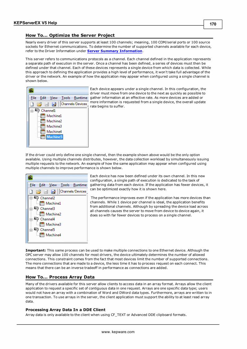
KEPServerEX V5 Help
How To... Optimize the Server ProjectNearly every driver of this server supports at least 100 channels; meaning, 100 COM/serial ports or 100 sourcesockets for Ethernet communications. To determine the number of supported channels available for each device,refer to the Driver Information under Server Summary Information.
This server refers to communications protocols as a channel. Each channel defined in the application representsa separate path of execution in the server. Once a channel has been defined, a series of devices must then bedefined under that channel. Each of these devices represents a single device from which data is collected. Whilethis approach to defining the application provides a high level of performance, it won't take full advantage of thedriver or the network. An example of how the application may appear when configured using a single channel isshown below.
Each device appears under a single channel. In this configuration, thedriver must move from one device to the next as quickly as possible togather information at an effective rate. As more devices are added ormore information is requested from a single device, the overall updaterate begins to suffer.
If the driver could only define one single channel, then the example shown above would be the only optionavailable. Using multiple channels distributes, however, the data collection workload by simultaneously issuingmultiple requests to the network. An example of how the same application may appear when configured usingmultiple channels to improve performance is shown below.
Each device has now been defined under its own channel. In this newconfiguration, a single path of execution is dedicated to the task ofgathering data from each device. If the application has fewer devices, itcan be optimized exactly how it is shown here.
The performance improves even if the application has more devices thanchannels. While 1 device per channel is ideal, the application benefitsfrom additional channels. Although by spreading the device load acrossall channels causes the server to move from device to device again, itdoes so with far fewer devices to process on a single channel.
Important: This same process can be used to make multiple connections to one Ethernet device. Although theOPC server may allow 100 channels for most drivers, the device ultimately determines the number of allowedconnections. This constraint comes from the fact that most devices limit the number of supported connections.The more connections that are made to a device, the less time it has to process request on each connect. Thismeans that there can be an inverse tradeoff in performance as connections are added.
How To... Process Array DataMany of the drivers available for this server allow clients to access data in an array format. Arrays allow the clientapplication to request a specific set of contiguous data in one request. Arrays are one specific data type; userswould not have an array with a combination of Word and DWord data types. Furthermore, arrays are written to inone transaction. To use arrays in the server, the client application must support the ability to at least read arraydata.
Processing Array Data In a DDE ClientArray data is only available to the client when using CF_TEXT or Advanced DDE clipboard formats.
www. kepware.com
170

KEPServerEX V5 Help
For client applications using Advanced DDE, the number of elements in the array is specified in the SPACKDDE_DATAHDR_TAG structure. Only single dimensional arrays are supported by this protocol. This structure shouldbe used when poking array data to the server.
For clients using CF_TEXT, one or two-dimensional arrays are supported. Data in each row is separated by a TAB(0x09) character and each row is terminated with a CR (0x0d) and a LF (0x0a) character. When a client wants topoke an array of data values, the text string written should have this delimiter format.
When poking to an Array tag in either format, the entire array does not need to be written, but the startinglocation is fixed. If attempting to poke data in an array format to a tag that was not declared as an array, only thefirst value in the array is written. If attempting to poke more data than the tag's array size, only as much data asthe tag's array size is written. If attempting to poke data while leaving some data values blank, the server usesthe last known value for that array element when writing back to the device. If the value in that register has beenchanged but has not been updated in the server, it is overwritten with the old value. For this reason, it is best tobe cautious when writing data to arrays.
Processing Array Data In an OPC ClientIn OPC clients that support arrays, the OPC item data value is actually a variant array data type. The OPC clientparses the array element data: some clients create sub tags for display purposes. For example, if the OPC clientcreated a tag in its database named 'Process,' and the associated OPC item was a single dimensional array of 5elements, it might create 5 tags named 'Process_1', 'Process2,' and so forth. Other clients (such as the OPCQuick Client) may display the data as Comma Separated Values (CSV).
How To... Properly Name a Channel, Device, Tag, and Tag GroupWhen naming a channel, device, tag, or tag group, the following characters are reserved or restricted:
l Periods.l Double quotation marks.l Leading underscores.l Leading or trailing spaces.
Note: Some of the restricted characters can be used in specific situations. For more information, refer to the listbelow.
1. Periods are used in aliases to separate the original channel name and the device name. For example, avalid name is "Channel1.Device1".
2. Underscores can be used after the first character. For example, a valid name is "Tag_1".
3. Spaces may be used within the name. For example, a valid name is "Tag 1".
How To... Resolve Comm Issues When the DNS/DHCP Device Connected to theServer is Power CycledCertain drivers support DNS/DHCP resolution for connectivity, which allows users to assign uniquedomain/network names for identification purposes. When starting and connecting to the network, the devicesrequest an IP address from the network DNS server. This process of resolving a domain name to an IP address forconnectivity takes time. For greater speed, the operating system caches all of the resolved IP/domain names andre-uses them. The resolved names are held in cache for two hours by default.
Important: The server fails to reconnect to a device when the name of the IP address associated with thedevice's domain / network changes. If this change is a result of the device being power cycled, it acquires a newIP. This change may also be a result of the IP being manually changed on the device. In both cases, the IPaddress that was being used no longer exists.
Because the server automatically flushes the cache every 30 seconds, the IP is forced to resolve. If this does notcorrect the issue, users can manually flush the cache by typing the command string "ipconfig /flushdns" in thePC's command prompt.
Note: For more information, refer to the following Microsoft Support articleDisabling and Modifying ClientSide DNS Caching.
How To... Select the Correct Network Cable
www. kepware.com
171

KEPServerEX V5 Help
Without prior experience of Ethernet enabled devices or serial to Ethernet converters, users may find selectingthe correct network cable a confusing task. There are generally two ways to determine the proper cable setup. Ifconnecting to the device or converter through a network hub or switch, users need Patch Cable. A Patch Cablegets its name from the days when a telephone operator-style board was used to patch or connect devices to eachother. If connecting directly to the device from the PC, however, users need a Crossover Cable. Both of thesecables can be purchased from an electronic or PC supply store.
Cable Diagrams
www. kepware.com
172

KEPServerEX V5 Help
How To... Use an Alias to Optimize a ProjectTo get the best performance out of a project, it is recommended that each device be placed on its own channel. Ifa project needs to be optimized for communication after it has been created, it can be difficult to change theclient application to reference the new item names. By using an alias map, however, users can allow the client tomake the legacy request to the new Configuration. To start, follow the instructions below.
Unoptimized: Channel with multiple devices.
Optimized: Channel with each device under a different channel.
1. To start, create a new channel for each device. Place the device under the new channel and then deletethe original channel.
2. Create aNew Alias for each device in the Alias Map. The alias name is the original channel and devicename separated by a period. For example, "Channel1.Device1". For information on reserved characters,refer toHow To... Properly Name a Channel, Device, Tag, and Tag Group.
www. kepware.com
173

KEPServerEX V5 Help
Note: The server validates any request for items against the alias map before responding back to the clientapplication with an error that the item does not exist.
How To... Use DDE with the ServerUsing DDE in Your ApplicationDynamic Data Exchange (DDE) is a Microsoft communications protocol that provides a method for exchangingdata between applications running on a Windows operating system. The DDE client program opens a channel tothe DDE server application and then requests item data using a hierarchy of the application (service) name, topicname, and item name.
Important: For DDE clients to connect to the server interface, the runtime must be allowed to interact with thedesktop. For more information, refer toHow to Allow Desktop Interactions.
Example 1: Accessing a Register Locally (Using the Default Topic)The syntax is <application>|<topic>!<item> where:
l application: DDE service namel topic: _ddedata*l item: Modbus.PLC1.40001
*This is the default topic for all DDE data that does not use an alias map entry.
Note: An example of the syntax is "MyDDE|_ddedata!Modbus.PLC1.40001".
Example 2: Accessing a Register Locally (Using an Alias Name as a Topic)The syntax is <application>|<topic>!<item> where:
l application: DDE service namel topic: ModPLC1*l item: 40001
*This is the topic using the alias map entry.
Note: An example of the syntax is "MyDDE|ModPLC1!40001" . For additional possible syntax, refer to the DDEclient's specific help documentation.
See Also:Project Properties - DDEProject Properties - FastDDE & SuiteLinkWhat is the Alias Map?
Note: For information on how to connect to remote applications using DDE, refer toUsing Net DDE Across aNetwork.
www. kepware.com
174

KEPServerEX V5 Help
How To... Use Dynamic Tag AddressingThis server can also be used to dynamically reference a physical device data address from the server. The serverdynamically creates a tag for the requested item. Users cannot browse for tags from one client that weredynamically added by another. Before adding tags dynamically, users should note the following:
l The correct syntax must be used for the data address. For more information on the specific driver'ssyntax, refer to its help documentation.
l If users do not specify the requested item's data type, it is set to the default setting by the application. Formore information on the specific driver's supported data types, refer to its help documentation.
Note: In the examples below, the Simulator Driver is used with a channel name of 'Channel1' and a device nameof 'Device1'.
Example 1: Using Dynamic Tag Addressing In a Non-OPC ClientTo get data from register 'K0001' in the simulated device, use an item ID of "Channel1.Device1.K001." Thedefault data type for this register is Short. Since non-OPC clients do not provide an update rate to the server, theDynamic tag's default update rate is 100 ms. Both data type and update rate can be overridden after the dynamicrequest is sent.
To override the tag defaults, use the commercial AT sign ('@') at the end of the item. If intending to add theregister as a DWord (unsigned 32-bit) data type, use an item ID of "Channel1.Device1.K0001@DWord." Tochange the default update rate to 1000 ms, use "Channel1.Device1.K0001@1000." To change both defaults, use"Channel1.Device1.K0001@DWord,1000."
Note: The client application must be able to accept special characters like the '@' in its address space.
Example 2: Using Dynamic Tag Addressing In an OPC ClientIn an OPC client, the same syntax can be used to override the data type if the client application does not provide away to specify a data type when the OPC item is added. Since the item's update rate is not used in OPC, there is noneed to override it.
Note: The client application must be able to accept special characters like the '@' in its address space.
How To... Use Ethernet EncapsulationEthernet Encapsulation mode is designed to provide communications with serial devices connected to terminalservers on the Ethernet network. A terminal server is essentially a virtual serial port that converts TCP/IPmessages on the Ethernet network to serial data. Once the message has been converted to serial form, users canconnect standard devices that support serial communications to the terminal server. The diagram below showshow to employ Ethernet Encapsulation mode.
www. kepware.com
175

KEPServerEX V5 Help
Note: For unsolicited drivers that support Ethernet Encapsulation, users must configure the port and theprotocol settings at the channel level. This allows the driver to bind to the specified port and process incomingrequests frommultiple devices. An IP address is not entered at the channel because the channel acceptsincoming requests from all devices.
Ethernet Encapsulation can be used over wireless network connections (such as 802.11b and CDPD packetnetworks) and has been developed to support a wide range of serial devices. By using a terminal server device,users can place RS-232 and RS-485 devices throughout the plant operations while still allowing a single localizedPC to access the remotely mounted devices. Furthermore, Ethernet Encapsulation mode allows an individualnetwork IP address to be assigned to each device as needed. While using multiple terminal servers, users canaccess hundreds of serial devices from a single PC.
Configuring Ethernet Encapsulation ModeTo enable Ethernet Encapsulation mode, open Channel Properties and then select the Communications tab.In the Connection Type drop-down menu, select Ethernet Encap.
Note: Only the drivers that support Ethernet Encapsulation allows the option to be selected.
www. kepware.com
176

KEPServerEX V5 Help
Note: The server's multiple channel support allows up to 16 channels on each driver protocol. This allows usersto specify one channel to use the local PC serial port and another channel to use Ethernet Encapsulation mode.
Important:When Ethernet Encapsulation mode is selected, the serial port settings (such as baud rate, databits, and parity) are unavailable. After the channel has been configured for Ethernet Encapsulation mode, usersmust configure the device for Ethernet operation. When a new device is added to the channel, the EthernetEncapsulation settings can be used to select an Ethernet IP address, an Ethernet Port number, and the Ethernetprotocol.
Note: The terminal server being used must have its serial port configured to match the requirements of the serialdevice to be attached to the terminal server.
How To... Use Net DDE Across a NetworkDDE provides a way to share data between Windows applications as long as they exist on the samemachine. NetDDE shares data from a DDE server located on a local PC with DDE client applications located on remote PCs. Moreinformation on how to configure a PC to support Net DDE is available online.
How To ... Work with Non-Normalized Floating Point ValuesA non-normalized floating point value is defined as Infinity, Not-a-Number (NaN), or as a Denormalized Number.For more information, refer to the table below.
Term DefinitionNon-NormalizedFloating Point Value
An IEEE-754 floating point number that is one of the following:
www. kepware.com
177

KEPServerEX V5 Help
l Negative Infinity to Quiet Negative NaN.l Positive Infinity to Quiet Positive NaN.l Negative Denormalized Values.l Positive Denormalized Values.
NaN A number that exists outside of the range that may be represented as floating points.There are two types of NaN representations: Quiet and Signaling.*
DenormalizedNumber
A non-zero floating point number whose magnitude is less than the magnitude of thesmallest IEEE 754-2008 value that may be represented for a Float or a Double.
l For Floats, these include numbers between -1.175494E-38 and -1.401298E-45 (Negative Denormalized) and 1.401298E-45 and 1.175494E-38 (PositiveDenormalized).
l For Doubles, these include numbers between -2.225074E-308 and -4.940657E-324 (Negative Denormalized) and 4.940657E-324 and2.225074E-308 (Positive Denormalized).
*A floating point value that falls within the Signaling NaN range is converted to a Quiet NaN before beingtransferred to a client for Float and Double data types. To avoid this conversion, use a single element floating-point array.
Handling Non-Normalized IEEE-754 Floating Point ValuesUsers can specify how a driver handles non-normalized IEEE-754 floating point values through the "Non-Normalized Value Should Be" parameter located in Channel Properties - Advanced. When Unmodified isselected, all values are transferred to clients without any modifications. For example, a driver that reads a 32-bitfloat value of 0xFF800000(-Infinity) transfers that value "as is" to the client. When Replaced with Zero isselected, certain values are replaced with zero before being transferred to clients. For example, a driver thatreads a 32-bit float value of 0xFF800000(-Infinity) are replaced with zero before being transferred to a client.
Note: For information on which values are replaced with zero before being transferred to clients, refer to thetables below.
IEEE-754 Range for 32-Bit Floating Point ValuesName Hexadecimal Range Decimal RangeQuiet -NaN 0xFFFFFFFF to 0xFFC00001 N/AQuiet +NaN 0x7FC00000 to 7FFFFFFF N/AIndeterminate 0xFFC00000 N/ASignaling -NaN 0xFFBFFFFF to 0xFF800001 N/ASignaling +NaN 0x7F800001 to 7FBFFFFF N/A-Infinity(Negative Overflow)
0xFF800000 ≤ -3.4028235677973365E+38
+Infinity(Positive Overflow)
0x7F800000 ≥ 3.4028235677973365E+38
Negative Normalized-1.m × 2(e-127)
0xFF7FFFFF to 0x80800000 -3.4028234663852886E+38 to -1.1754943508222875E-38
Negative Denormalized-0.m × 2(-126)
0x807FFFFF to 0x80000001 -1.1754942106924411E-38 to -1.4012984643248170E-45(-7.0064923216240862E-46)
Positive Denormalized0.m × 2(-126)
0x00000001 to 0x007FFFFF (7.0064923216240862E-46) *1.4012984643248170E-45to 1.1754942106924411E-38
Positive Normalized1.m × 2(e-127)
0x00800000 to 0x7F7FFFFF 1.1754943508222875E-38 to3.4028234663852886E+38
IEEE-754 Range for 64-Bit Floating Point ValuesName Hexadecimal Range Decimal RangeQuiet -NaN 0xFFFFFFFFFFFFFFFF to
0xFFF8000000000001N/A
Quiet +NaN 0x7FF8000000000000 to0x7FFFFFFFFFFFFFFF
N/A
Indeterminate 0xFFF8000000000000 N/A
www. kepware.com
178

KEPServerEX V5 Help
Signaling -NaN 0xFFF7FFFFFFFFFFFF to0xFFF0000000000001
N/A
Signaling +NaN 0x7FF0000000000001 to0x7FF7FFFFFFFFFFFF
N/A
-Infinity(Negative Overflow)
0xFFF0000000000000 ≤ -1.7976931348623158E+308
+Infinity(Positive Overflow)
0x7FF0000000000000 ≥ 1.7976931348623158E+308
Negative Normalized-1.m × 2(e-1023)
0xFFEFFFFFFFFFFFFF to0x8010000000000000
-1.7976931348623157E+308 to -2.2250738585072014E-308
Negative Denormalized-0.m × 2(-1022)
0x800FFFFFFFFFFFFF to0x8000000000000001
-2.2250738585072010E-308 to -4.9406564584124654E-324 (-2.4703282292062328E-324)
Positive Denormalized0.m × 2(-1022)
0x0000000000000001 to0x000FFFFFFFFFFFFF
(2.4703282292062328E-324) *4.9406564584124654E-324 to2.2250738585072010E-308
Positive Normalized1.m × 2(e-1023)
0x0010000000000000 to0x7FEFFFFFFFFFFFFF
2.2250738585072014E-308 to1.7976931348623157E+308
Device Demand PollDevice Demand Poll is useful for customers that require full control of polling devices from their clientapplications. It is particularly helpful in SCADA industries like Oil & Gas, Water/Waste Water, Electric, and othersthat may experience significant communication delays.
Many client-side SCADA systems either do not have configurable scan rates or have scan rates whose minimumvalue is too long for the data updates that are required by SCADA operators. To bypass this limitation, the SCADAsystem can perform writes to the Device Demand Poll tags available in the server. In this scenario, each device inthe server exposes a _DemandPoll tag that polls all referenced tags on the device when written to by a client.During the poll, the _DemandPoll tag becomes True (1). It returns to False (0) when the final active tag signalsthat the read requests have completed. Subsequent writes to the _DemandPoll tag fails until the tag value returnsto False. The demand poll respects the read/write duty cycle for the channel. Client-side SCADA scripts (such asa Refresh button script) can then be developed to write to the _DemandPoll tag and cause a poll to occur. The pollresults are passed on to the client application. For more information, refer to System Tags.
Note: The procedure described above is not OPC-compliant behavior. If this is a problem, it is recommended thatcommunications be separated onto two devices. One device can use the classic OPC update interval, and theother device can set the Scan Mode to "Do not scan, demand poll only" and only poll when the _DemandPoll tag iswritten to.
Regardless of whether Device Demand Poll is being utilized, clients that are limited by tag scan rates may alsoencounter operator wait time due to the server complying with the OPC client's group update rate. To circumventthis OPC-compliant behavior, users can configure the "Ignore group update rate, return data as soon as it isavailable" setting. This returns the poll results immediately and disregards the update interval. For moreinformation, refer to Project Properties - OPC DA Compliance.
See Also:Device Properties - Scan Mode
www. kepware.com
179
KEPServerEX V5 Help
Message DescriptionsThe following categories of messages may be generated. Click on a link for a list of messages.
General Operation System MessagesiFIX MessagesServer Administration MessagesServer Configuration MessagesServer Runtime Messages
General Operation System MessagesThe following messages may be generated. Click on the link for a description of the message.
Dialing <phone number> on line <modem name>.Dialing aborted on <modem name>.Dialing on line <modem name> canceled by user.Failed to open modem line <modem name> [TAPI error].Hardware error on line <modem name>.Incoming call detected on line <modem name>.Line <modem name> connected.Line <modem name> connected at <baud rate> baud.Line <modem name> disconnected.Line <modem name> is already in use.Line dropped at remote site on <modem name>.Modem line closed: <modem name>.Modem line opened: <modem name>.Modem to Modem DCE: <connection parameters>.MODEMSETTINGS unavailable.No comm handle provided on connect for line <modem name>.No dial tone on <modem name>.Remote line is busy on <modem name>Remote line is not answering on <modem name>.Socket error <code> occurred on <device name>. Operation <operation name> failed because<reason>.TAPI configuration has changed, reinitializing...TAPI line initialization failed: <modem name>.The phone number is invalid <phone number>.Unable to apply Modem Configuration on line <modem name>.Unable to dial on line <modem name>.Unable to start Net DDE.
Dialing <phone number> on line <modem name>.Error Type:Informational
Source:TAPI Manager
Possible Cause:TAPI manager is dialing the specified number for the server.
Solution:N/A
Dialing aborted on <modem name>.Error Type:Informational
Source:TAPI Manager
www. kepware.com
180
KEPServerEX V5 Help
Possible Cause:Dialing was aborted by the user.
Solution:N/A
Dialing on line <modem name> canceled by user.Error Type:Informational
Source:TAPI Manager
Possible Cause:The server has canceled its request to dial a device on the specified line.
Solution:N/A
Failed to open modem line <modem name> [TAPI error].Error Type:Error
Source:TAPI Manager
Possible Cause:TAPI attempted to open the modem line for the server and encountered an error.
Solution:Correct the specified error. Then, re-attempt to open the modem line.
Hardware error on line <modem name>.Error Type:Error
Source:TAPI Manager
Possible Cause:A hardware error was returned after a request was made for a tag in a device connected to the modem.
Solution:Disable data collection on the device. Only enable it after the modem has connected to the destination modem.
Note:The error occurs on first scan and is not repeated.
Incoming call detected on line <modem name>.Error Type:Informational
Source:TAPI Manager
Possible Cause:The modem has detected an incoming call on the phone line to which it is connected. If the modem is set toautomatically answer, it answers the incoming call.
Solution:
www. kepware.com
181

KEPServerEX V5 Help
N/A
Line <modem name> connected.Error Type:Informational
Source:TAPI Manager
Possible Cause:The modem line is connected.
Solution:None available.
Line <modem name> connected at <baud rate> baud.Error Type:Informational
Source:TAPI Manager
Possible Cause:The modem connected to the dialed modem at the specified rate.
Solution:N/A
Line <modem name> disconnected.Error Type:Informational
Source:TAPI Manager
Possible Cause:TAPI manager has disconnected the modem for the server.
Solution:N/A
Line <modem name> is already in use.Error Type:Warning
Source:TAPI Manager
Possible Cause:An attempt was made to open the modem line but could not be completed because it was already open.
Solution:Find the application that is currently holding the modem open. Then, either close or release it.
Line dropped at remote site on <modem name>.Error Type:Informational
Source:TAPI Manager
www. kepware.com
182
KEPServerEX V5 Help
Possible Cause:The remote modem has hung up and dropped the call.
Solution:N/A
Modem line closed: <modem name>.Error Type:Warning
Source:TAPI Manager
Possible Cause:The modem line was closed by the TAPI manager.
Solution:This message is normally posted when a project is stopped and the driver no longer needs the modem line.
Modem line opened: <modem name>.Error Type:Warning
Source:TAPI Manager
Possible Cause:The modem line was opened by the TAPI manager.
Solution:This message is normally posted when a project is started and the driver needs the modem line.
Modem to Modem DCE: <connection parameters>.Error Type:Informational
Source:TAPI Manager
Possible Cause:Modem connection is established to the remote modem. Distributed Computing Environment DCE successfulcommunication.
Variants:
Modem to Modem DCE, Error controlPossible Cause:Error control has been set in the Modem Configuration dialog.
Modem to Modem DCE, Forced error controlPossible Cause:Forced error control has been set in the Modem Configuration dialog.
Modem to Modem DCE, Hardware flow controlPossible Cause:Hardware Flow control has been set in the Modem Configuration dialog.
Modem to Modem DCE, Software flow controlPossible Cause:Software Flow control has been set in the Modem Configuration dialog.
www. kepware.com
183

KEPServerEX V5 Help
Solution:N/A
MODEMSETTINGS unavailable.Error Type:Informational
Source:TAPI Manager
Possible Cause:The Modem Configuration dialog has been loaded but the modem settings for the selected modem are notaccessible.
Solution:If the modem was recently installed, try stopping and restarting the server. The PCmay need to be rebooted forthe modem settings to become available.
No comm handle provided on connect for line <modem name>.Error Type:Warning
Source:TAPI Manager
Possible Cause:An attempt was made to connect to the modem line with no specified COMM handle.
Solution:Make sure the modem is both installed and initialized correctly.
No dial tone on <modem name>.Error Type:Informational
Source:TAPI Manager
Possible Cause:There is no dial tone on the line.
Solution:
1. Make sure that the modem is connected.
2. The phone line may require a code or number to get an outside line or dial tone. Make sure that the Modemsettings are correctly set to automatically dial this number when a connection is made to the modem.
Remote line is busy on <modem name>.Error Type:Warning
Source:TAPI Manager
Possible Cause:The dialed location is busy.
Solution:
www. kepware.com
184
KEPServerEX V5 Help
Hang up and try again later.
Remote line is not answering on <modem name>.Error Type:Informational
Source:TAPI Manager
Possible Cause:The dialed modem is not answering the call.
Solution:
1. Hang up and then try again later.
2. Verify that the remote modem is configured to answer calls.
Socket error <code> occurred on <device name>. Operation <operationname> failed because <reason>.Error Type:Warning
Possible Cause:Ethernet encapsulation communications with <device name> failed during the specified socket operation.Possible operations include:
l connectl wait for send data (test socket before sending)l sendl wait for receive data (test socket before receiving)l receive
Both error <code> and detailed <reason> are provided by the operating system. This error is posted when the<device name> is in an error state (_Error is true).
Solution:The <reason> details why the error occurred and suggests a remedy when appropriate.
See Also:See "Additional Ethernet Encapsulation Settings" on page 57
TAPI configuration has changed, reinitializing...Error Type:Informational
Source:TAPI Manager
Possible Cause:The TAPI Line configuration has changed. TAPI is now reinitializing the modem with the changes.
Solution:None available.
TAPI line initialization failed: <modem name>.Error Type:Warning
Source:
www. kepware.com
185

KEPServerEX V5 Help
TAPI Manager
Possible Cause:The telephony service is not required to be running for the Runtime to start. When the service is disabled and aserial driver is added to the project, this error message is reported.
Solution:
1. If modem communications are not going to be used, no action is required.
2. If modem communications are required, the telephony service needs to be started on the PC.
The phone number is invalid <phone number>.Error Type:Informational
Source:TAPI Manager
Possible Cause:The phone number entered and dialed is incorrectly formatted for the local or long distance settings.
Solution:Open the Modem Configuration and verify the number formats required. Then, re-dial the number with thecorrect format.
Unable to apply Modem Configuration on line <modem name>.Error Type:Warning
Source:TAPI Manager
Possible Cause:TAPI Manager was unable to apply the configuration changes to the server.
Solution:
1. Verify the cabling to the modem.
2. Verify that the modem is set to accept configuration changes.
3. Verify that the modem is not being used by another application.
Unable to dial on line <modem name>.Error Type:Informational
Source:TAPI Manager
Possible Cause:The server is unable to have the modem dial the number because the modem is not in a state that allows dialing.
Solution:To dial a number, the line must be idle. Monitor the _Mode Modem tag and dial when it indicates an idle state.
Unable to start Net DDE.Error Type:Warning
www. kepware.com
186
KEPServerEX V5 Help
Source:DDE
Possible Cause:
1. The server project is configured to allow Net DDE but was unable to launch Net DDE.
2. Net DDE servers are not enabled to run as a service on this PC or have been completely disabled.
Solution:
1. Go to the service manager and ensure that Net DDE services is enabled and set to automatically start.
2. Check with the IT administrator and make sure that Net DDE services are allowed. If not, have the localpolicy changed to allow Net DDE.
iFIX MessagesThe following messages may be generated. Click on the link for a description of the message.
Attempt to add iFIX PDB item <item name> failed.Failed to enable iFIX PDB support for this server [OS error = n].Unable to enable iFIX PDB support for this server.Unable to read <tag name> on device <channel name/device name>.
Attempt to add iFIX PDB item < item name> failed.Error Type:Informational
Source:NIO
Possible Cause:The server was not able to add the NIO interface.
Solution:The server could be in use by a client application. In this case, changes (such as, new interfaces) can bedisabled.
Failed to enable iFIX PDB support for this server [OS error = n].Error Type:Informational
Source:NIO
Possible Cause:The server was unable to access the registry to enable the NIO interface.
Solution:This error generally concerns user account access rights. Users must have administrator privileges to write tothe registry.
Unable to enable iFIX PDB support for this server.Error Type:Informational
Source:NIO
Possible Cause:The interface cannot be enabled for use because it may already be enabled for someone else.
www. kepware.com
187

KEPServerEX V5 Help
Solution:If possible, stop the other application that is using the interface.
Unable to read <tag name> on device <channel name/device name>.Error Type:Warning
Possible Cause:A database tag has been created within the iFIX database containing an invalid I/O address.
Solution Steps:
1. Delete the tag from the iFIX database (if not already deleted).
2. Delete the "<server project>_FIX.ini" file.
3. Export the PDB database from the iFIX Database Manager.
4. Re-import the exported file so that "<server project>_FIX.ini" is recreated with the current list of iFIXdatabase items. This allows each item that is in the iFIX database to be re-validated with the server.
See Also:Project Startup for iFIX Applications
Server Administration MessagesThe following messages may be generated. Click on the link for a description of the message.
Cannot export user information until all passwords have been updated.Password for user <name> has been changed.Password for user 'Administrator' was reset by <Windows user>.Password reset for user 'Administrator' failed. <Windows user> is not a Windows administrator.Permissions definition has changed on user group <name>.User <name> has been created as a member of user group <name>.User <name> has been disabled.User <name> has been enabled.User <name> has been renamed to <new name>.User <name> moved from user group <old group> to <new group>.User group <name> has been created.User group <name> has been disabled.User group <name> has been enabled.User group <name> has been renamed to <new name>.User information replaced by import from <file name>.
Cannot export user information until all passwords have been updated.Error Type:Warning
Source:Administration
Possible Cause:The project contains user passwords that were set using an older server version.
Solution:Change the user passwords and attempt the export again.
Password for user <name> has been changed.Error Type:Informational
www. kepware.com
188
KEPServerEX V5 Help
Source:Administration
Possible Cause:The password has been changed for the specified user.
Solution:N/A
Password for user 'Administrator' was reset by <Windows user>.Error Type:Informational
Source:Administration
Possible Cause:The password for the Administrator has been reset.
Solution:N/A
Password reset for user 'Administrator' failed. <Windows user> is not aWindows administrator.Error Type:Error
Source:Administration
Possible Cause:An attempt was made to reset a password by a user who is not a Windows Administrator.
Solution:Reset the password from aWindows Administrator account.
Permissions definition has changed on user group <name>.Error Type:Informational
Source:Administration
Possible Cause:The access rights or privileges have changed for the specified user group.
Solution:N/A
User <name> has been created as a member of user group <name>.Error Type:Informational
Source:Administration
Possible Cause:The specified user has been created as a member of the specified user group.
Solution:
www. kepware.com
189
KEPServerEX V5 Help
N/A
User <name> has been disabled.Error Type:Informational
Source:Administration
Possible Cause:The specified user has been disabled.
Solution:N/A
User <name> has been enabled.Error Type:Informational
Source:Administration
Possible Cause:The specified user has been enabled.
Solution:N/A
User <name> has been renamed to <new name>.Error Type:Informational
Source:Administration
Possible Cause:The specified user has been renamed.
Solution:N/A
User <name> moved from user group <old group> to <new group>.Error Type:Informational
Source:Administration
Possible Cause:The specified user has been moved to a new user group.
Solution:N/A
User group <name> has been created.Error Type:Informational
Source:Administration
www. kepware.com
190
KEPServerEX V5 Help
Possible Cause:The specified user group has been created.
Solution:N/A
User group <name> has been disabled.Error Type:Informational
Source:Administration
Possible Cause:The specified user group has been disabled.
Solution:N/A
User group <name> has been enabled.Error Type:Informational
Source:Administration
Possible Cause:The specified user group has been enabled.
Solution:N/A
User group <name> has been renamed to <new name>.Error Type:Informational
Source:Administration
Possible Cause:The specified user group has been renamed.
Solution:N/A
User information replaced by import from <file name>.Error Type:Informational
Source:Administration
Possible Cause:The previous user information has been replaced with information from the specified import file.
Solution:N/A
www. kepware.com
191

KEPServerEX V5 Help
Server Configuration MessagesThe following messages may be generated. Click on the link for a description of the message.
<device name> device driver loaded successfully.<driver name> device driver unloaded from memory.<driver name> device driver was not found or could not be loaded.<driver name> driver does not currently support XML persistence.<plug-in> plug-in was not found or could not be loaded.<COM/Modem ID> is already in use by channel <channel name>.<COM/Modem ID> is already in use on <virtual network>.<Virtual network> already contains a shared connection.A client application has <enabled/disabled> auto-demotion on device <device name>.A connection share pairing on <COM/Modem ID> is not supported by drivers <driver name> and<driver name>.Closing project <project name>.Created backup of project <project name> to <file location>.Error importing CSV tag record <record number>: <tag name> is not a valid tag group name.Error importing CSV tag record <record number>: <tag name> is not a valid tag name.Error importing CSV tag record <record number>: Missing address.Error importing CSV tag record <record number>: Tag or group name exceeds 256 characters.Failed to reset channel diagnostics.Failed to retrieve Runtime project.Invalid Ethernet encapsulation IP <IP address>.Invalid or missing Modem Configuration on channel <channel name, substituting <modem>.Invalid XML document <XML name>.Maximum channel count exceeded for the lite version <driver name> driver license.Maximum device count exceeded for the lite version <driver name> driver license.Maximum Runtime tag count exceeded for the lite version <driver name> driver license.Modem initialization failed on channel <channel name>.Opening project <project name>.Project containing custom access control permissions cannot be saved as XML.Required schema file <schema name> not found.Runtime project update failed.Starting OPC diagnostics.Stopping OPC diagnostics.Unable to add channel due to driver-level failure.Unable to add device due to driver-level failure.Unable to backup project file to <file path>.Unable to begin device discovery on channel <channel name>.Unable to launch OPC Quick Client [Path: <path> OS error: <error>].Unable to load driver DLL <driver name>.Unable to load the <driver name> driver because more than one copy exists (<driver name> and<driver name>.Unable to use network adapter <adapter> on channel <channel name>. Using default networkadapter.Validation error on <tag name>: Invalid scaling parameters.
<device name> device driver loaded successfully.Error Type:Informational
Possible Cause:The Configuration was able to successfully load the driver into its workspace.
Solution:N/A
<driver name> device driver unloaded from memory.Error Type:Informational
www. kepware.com
192
KEPServerEX V5 Help
Source:Configuration
Possible Cause:The driver was unloaded from the server's memory space because it was no longer needed.
SolutionN/A
<driver name> device driver was not found or could not be loaded.Error Type:Error
Source:Configuration
Possible Cause:An attempt was made to load a project with a channel using the specified driver which could not be found orloaded.
1. If the project has been moved from one PC to another, the required drivers may have not been installedyet.
2. The specified driver may have been removed from the installed server.
3. The specified driver may be the wrong version for the installed server version.
Solution:
1. Re-run the server install and add the required drivers.
2. Re-run the server install and re-install the specified drivers.
3. Ensure that a driver has not been placed in the installed server directory (which is out of sync with theserver version).
<Driver name> driver does not currently support XML persistence.Error Type:Warning
Source:Configuration
Possible Cause:The specified driver does not support XML formatting.
Solution:Save the project in .opf format.
<Plug-in> plug-in was not found or could not be loaded.Error Type:Error
Source:Configuration
Possible Cause:The server project being loaded is using a plug-in that cannot be found.
Solution:Re-run the server install and select the specified plug-in for installation.
www. kepware.com
193

KEPServerEX V5 Help
<COM/Modem ID> is already in use by channel <channel name>.Error Type:Informational
Source:Configuration
Possible Cause:The COM ID or modem ID is already in use on the specified channel.
Solution:Specify a different COM ID or modem ID.
<COM/Modem ID> is already in use on <virtual network>.Error Type:Informational
Source:Configuration
Possible Cause:The COM ID or Modem ID is already in use on the specified virtual network.
Solution:Specify a different COM ID or Modem ID.
See Also:Channel Properties - Advanced
<Virtual network> already contains a shared connection.Error Type:Informational
Source:Configuration
Possible Cause:The specified virtual network already contains a shared connection.
Solution:Re-attempt the shared connection on another virtual network.
A client application has <enabled/disabled> auto-demotion on device <devicename>.Error Type:Informational
Source:Configuration
Possible Cause:A client application that is connected to the server has enabled or disabled Auto Demotion on the specified device.
Solution:To restrict the client application from doing this, disable its ability to write to System-level tags through the OPCDA settings.
www. kepware.com
194
KEPServerEX V5 Help
A connection share pairing on <COM/Modem ID> is not supported by drivers<driver name> and <driver name>.Error Type:Informational
Source:Configuration
Possible Cause:An attempt was made to share a connection on the specified COM ID or Modem ID that is not supported by thedrivers.
Solution:Change the connection share pairing to one that is supported by the specified drivers.
Closing project <project name>.Error Type:Informational
Source:Configuration
Possible Cause:The specified project was closed.
Solution:N/A
Created backup of project <project name> to <file location>.Error Type:Informational
Source:Configuration
Possible Cause:The server was able to successfully backup the server project.
Solution:N/A
Error importing CSV tag record <record number>: <tag name> is not a validtag group name.Error Type:Warning
Source:Configuration
Possible Cause:A tag group has been imported in the CSV file that is incorrectly formatted.
Solution:Correct the syntax in the CSV file and then re-import.
Note:Tag group names may not start with '_' (Underscores), '.' (Periods) or ' ' (spaces).
www. kepware.com
195
KEPServerEX V5 Help
Error importing CSV tag record <record number>: <tag name> is not a validtag name.Error Type:Warning
Source:Configuration
Possible Cause:A tag has been imported in the CSV file that is incorrectly formatted.
Solution:Correct the syntax in the CSV file and then re-import.
Note:Tag names may not start with '_' (Underscores), '.'(Periods) or ' ' (spaces).
Error importing CSV tag record <record number>: Missing address.Error Type:Warning
Source:Configuration
Possible Cause:An attempt was made to import a CSV file. The tag was configured in the CSV without an address specified in theaddress field.
Solution:Add an address to the specified record and re-run the CSV import.
Error importing CSV tag record <record number>: Tag or group name exceeds256 characters.Error Type:Warning
Source:Configuration
Possible Cause:A tag or tag group has been imported from a CSV file that has a name exceeding the 256 character limit.
Solution:Correct the specified name in the CSV file and then re-import.
Note:The tag record is calculated from the List of tags in the CSV file, beginning with the first item listed.
Failed to reset channel diagnostics.Error Type:Warning
Source:Configuration
Possible Cause:A failed attempt was made to reset the channel diagnostics data.
Solution:Ensure that diagnostics are enabled for this channel.
www. kepware.com
196
KEPServerEX V5 Help
See Also:Channel Diagnostics
Channel PropertiesFailed to retrieve Runtime project.Error Type:Error
Source:Configuration
Possible Cause:The Configuration connected to the Runtime, but was unable to load the project for editing.
Solution:
1. The Configuration could be a different version than the Runtime. Ensure that the client and Runtimeversions can work together. If not, install the correct Configuration.
2. The project loaded by the Runtime may have been deleted. Verify that the project still exists; if it does not,restore it.
Invalid Ethernet encapsulation IP <IP address>.Error Type:Warning
Source:Configuration
Possible Cause:The IP address that is specified for a device on an Ethernet Encapsulated channel is not a valid IP address.
Solution:Correct the IP in the XML file and then re-load the project.
Note:This error occurs when loading XML formatted projects. These projects have usually been created or edited witha third-party XML software.
Invalid or missing modem configuration on channel <channel name>,substituting <modem>.Error Type:Warning
Source:Configuration
Possible Cause:A server project was loaded that uses a modem unavailable on this PC.
Solution:
1. Change the Modem Configuration in the project to use a supported modem.
2. Add the specified modem to the PC's Configuration.
Invalid XML document <XML name>.Error Type:Error
www. kepware.com
197

KEPServerEX V5 Help
Source:Configuration
Possible Cause:The server attempted to open a project formatted with XML and was unable to parse the XML file.
Solution:If the server project was edited using a third party XML editor, verify that the format is correct via the schemasfor the server and drivers.
Maximum channel count exceeded for the lite version <driver name> driverlicense.Error Type:Warning
Source:Configuration
Possible Cause:The specified driver was activated with a lite license, which limits the number of channels that can be configured.
Solution:
1. Verify the number of channels authorized by the license. Then, correct the project design to use only thatnumber of channels.
2. If more channels are needed or the lite activation is incorrect, contact a sales representative aboutupgrading the license to a version that supports the number of desired channels.
Consult Event Log and the License Utility Help for licensing information.
Maximum device count exceeded for the lite version <driver name> driverlicense.Error Type:Warning
Source:Configuration
Possible Cause:The specified driver was activated with a lite license, which limits the number of devices that can be configured.
Solution:
1. Verify the number of devices authorized by the license. Then, correct the project design to use only thatnumber of devices.
2. If more devices are needed or the lite activation is incorrect, contact a sales representative aboutupgrading the license to a version that supports the number of desired devices.
Consult Event Log and the License Utility Help for licensing information.
Maximum Runtime tag count exceeded for the lite version <driver name>driver license.Error Type:Error
Source:Configuration
Possible Cause:
www. kepware.com
198
KEPServerEX V5 Help
The specified driver was activated with a lite license, which limits the number of tags that can be configured.
Solution:
1. Verify the number of tags authorized by the license and then correct the project design to use only thatnumber of tags.
2. If more tags are needed or if the lite activation is incorrect, contact a sales representative aboutupgrading the license to a version that supports the number of desired tags.
Consult Event Log and the License Utility Help for licensing information.
Modem initialization failed on channel <channel name>.Error Type:Error
Source:Configuration
Possible Cause:A server made a failed attempt to initialize the modem assigned to the specified channel.
Solution:Refer to the additional events posted with details on the initialization errors.
Opening project <project name>.Error Type:Informational
Source:Configuration
Possible Cause:The specified project was opened.
Solution:N/A
Project containing custom access control permissions cannot be saved as XML.Error Type:Error
Source:Configuration
Possible Cause:An attempt was made to save a project that contains custom access control permissions as XML.
Solution:Save the project as an .opf file.
Required schema file <schema name> not found.Error Type:Error
Source:Configuration
Possible Cause:A project formatted with XML was loaded but the specified schema file was not found in the schemas folder.
www. kepware.com
199

KEPServerEX V5 Help
Solution:Re-run the server install and make sure that all the drivers are selected. This installs any missing schema files.
Runtime project update failed.Error Type:Error
Source:Configuration
Possible Cause:The attempted update to the Runtime project failed.
Solution:
1. The user may not have permission to make changes to the project. Log in to the User Manager with thecorrect user credentials.
2. The folder containing the project may be locked to changes. Verify that all users with access to the projecthave permissions in the folder.
Starting OPC diagnostics.Error Type:Informational
Source:Configuration
Possible Cause:OPC diagnostics captures were started by a connected Configuration.
Solution:N/A
Stopping OPC diagnostics.Error Type:Informational
Source:Configuration
Possible Cause:OPC diagnostics capturing was stopped by a connected Configuration.
Solution:N/A
Unable to add channel due to driver-level failure.Error Type:Error
Source:Configuration
Possible Cause:An attempt was made to add a channel to the server and it failed due to issues in the driver.
Solution:
www. kepware.com
200
KEPServerEX V5 Help
1. Refer to the additional messages posted with information on the driver-level error.
2. If necessary, contact Technical Support for additional help.
Unable to add device due to driver-level failure.Error Type:Error
Source:Configuration
Possible Cause:An attempt was made to create a device in a server project, but it failed due to an issue in the driver.
Solution:Refer to the additional error messages, to learn about the driver error.
Unable to backup project file to <file path>.Error Type:Error
Source:Configuration
Possible Cause:The server was unable to back up the server project to the specified file location.
Solution:
1. Ensure that the destination file is not locked by another application.
2. Ensure that the destination file, along with the folder where it is located, has read/write access.
Note:This error is most likely due to read/write access permissions.
Unable to begin device discovery on channel <channel name>.Error Type:Informational
Source:Configuration
Possible Cause:
1. The driver could not be started.
2. The server's demonstration time period has expired.
Solution:
1. Verify that the driver is licensed
2. Verify that the server is running.
3. Restart the server to reset the demonstration time period.
See Also:
www. kepware.com
201
KEPServerEX V5 Help
Unable to launch OPC Quick Client [Path: <path> OS error: <error>].Error Type:Error
Source:Configuration
Possible Cause:An attempt was made to launch the OPC Quick Client from the Configuration and it failed.
Solution:
1. Verify that the OPC Quick Client is installed in the specified location. If not, re-run the server installationand select it for installation.
2. Verify that the required access rights to launch the OPC Quick Client from its specified location are had.
3. Contact Technical Support for assistance in determining the fault from the OS error.
Unable to load driver DLL <driver name>.Error Type:Error
Source:Configuration
Possible Cause:The specified driver could not be loaded when the project started.
Solution:
1. Verify the version of the driver that is installed. Check the OPC server's website to see if the driver versionis for the version of the server that is installed. If not, correct the server or re-run the server install.
2. If the driver is found to be corrupted, delete it and then re-run the server install.
Note:This problem is usually due to corrupted driver DLLs or drivers that are not in sync with the server version.
Unable to load the <driver name> driver because more than one copy exists(<driver name> and <driver name>).Error Type:Error
Source:Configuration
Possible Cause:There are multiple versions of the driver DLL existing in the driver's folder in the server.
Solution:Contact Technical support and verify which version should be installed for the version of the server being run.Remove the driver that is invalid and then restart the server and load the project.
Unable to use network adapter <adapter> on channel <channel name>. Usingdefault network adapter.Error Type:Warning
Source:Configuration
www. kepware.com
202

KEPServerEX V5 Help
Possible Cause:The network adapter specified in the project does not exist on this PC. The server defaults to using the defaultnetwork adapter.
Solution:Select the network adapter to be used on the PC and then save the project.
See Also:Channel Properties - Network Interface
Validation error on <tag name>: Invalid scaling parameters.Error Type:Warning
Source:Configuration
Possible Cause:An attempt was made to set invalid scaling parameters on the specified tag.
Solution:Correct the scaling parameters and then save the tag.
See Also:Tag Properties - Scaling
Server Runtime MessagesThe following messages may be generated. Click on the link for a description of the message.
<driver name> device driver was not found or could not be loaded.<server name> server started.<server runtime> successfully configured to run as a system service.<server runtime> successfully removed from the service control manager database.Access denied to user <name> requesting <permission> on <object path>.Attempt to add DDE item <item name> failed.Attempt to add FastDDE/SuiteLink item <tag name> failed.Attempt to add OPC client item <item name> failed.Attempting to automatically generate tags for device <device name>.Auto generation for tag <tag name> already exists and will not be overwritten.Auto generation produced too many overwrites, stopped posting error messages.Cannot delete <object path> because it belongs to a client access policy defined under user group<user group name>.Channel diagnostics started on channel <channel name>.Channel diagnostics stopped on channel <channel name>.Completed automatic tag generation for device <device name>.Configuration session assigned to <user name> as default user has ended.Configuration session assigned to <user name> demoted to read only.Configuration session assigned to <user name> promoted to write access.Configuration session started by <user name>.Configuration TCP/IP port number changed to <port number>.Data collection is <enabled/disabled> on device <device name>.DDE client attempt to add topic <topic> failed.Delete object <item name> failed.Demo timer started. <days> <hours> <minutes> <seconds>.Demo timer updated. <time remaining>.Demonstration time has expired.Device <device name> has been auto-demoted.Device <device name> has been auto-promoted to determine if communications can be re-established.Failed to upload project XML.
www. kepware.com
203

KEPServerEX V5 Help
FLEXnet Licensing Service must be enabled to process your license.Module <module> is unsigned or has a corrupt signature.Move object <group> to <group> failed.Move object <object name> failed.No device driver DLLs were loaded.Runtime project replaced from <project location>.Simulation mode is <enabled/disabled> on device <device name>.Starting <driver name> device driver.Starting <plug-in name> plug-in.Stopping <driver name> device driver.Stopping <plug-in name> plug-in.The tier information for feature <feature> is invalid.Unable to generate a tag database for device <device name>. Reason: <reason>.Unable to generate a tag database for device <device name>. The device is not responding.Unable to load project <project name>.Unable to write to item <item name>.Update of object <object> failed.Write request rejected on item reference <item name> since the device it belongs to is disabled.Write request rejected on read-only item reference <item name>.
<Driver name> device driver was not found or could not be loaded.Error Type:Warning
Possible Cause:A project using a driver that has not been installed or that is not compatible with the current server/driverversion was started but could not properly launch.
Solution:
1. If the driver is not installed, re-run the install and select the driver.
2. If the driver is installed, verify the version that the project was created with and install a compatibleversion on the running PC.
Note:Every attempt is made to ensure backwards compatibility in the server so that projects created in older versionsmay be loaded in newer versions. However, since new versions of the server and driver may have properties andconfigurations that do not exist in older version, users may not be able to open or load a project created in anewer version of the server in an older version.
<Server name> server started.Error Type:Informational
Source:Runtime
Possible Cause:The server Runtime has started successfully.
Solution:N/A
<Server Runtime> successfully configured to run as a system service.Error Type:Informational
Possible Cause:The server Runtime process has been switched from "Interactive" to "System service" mode.
www. kepware.com
204
KEPServerEX V5 Help
Solution:None
<Server runtime> successfully removed from the service control managerdatabase.Error Type:Informational
Possible Cause:The server runtime process has been switched from "System Service" to "Interactive" mode.
Solution:None
Access denied to user <name> requesting <permission> on <object path>.Error Type:Warning
Source:Runtime
Possible Cause:A request was made to an object that the user does not have permission to access.
Solution:Verify the permissions assigned to the user. Then, change or reattempt the request.
See Also:Settings - User Manager
Attempt to add DDE item <item name> failed.Error Type:Error
Source:Runtime
Possible Cause:An attempt to add an item from a DDE client failed.
Solution:
1. If attempting to add an item dynamically to a tag group that is not supported in the server, add dynamictags to the device level only.
2. If attempting to add an item dynamically using the incorrect address syntax, correct the syntax and tryagain.
3. If attempting to add an item not created as a static tag in the server, add the tag in the server then addthe item from the client.
4. If attempting to add an item with incorrect syntax, correct the syntax and try again.
Attempt to add FastDDE/SuiteLink item <tag name> failed.Error Type:Error
Source:Runtime
Possible Cause:
www. kepware.com
205

KEPServerEX V5 Help
1. The user attempted to add an item from a FastDDE/Suitelink client that was not a static tag in the server.
2. The user attempted to add an item from a FastDDE/Suitelink client that had incorrect syntax.
Solution:
1. Check the item syntax and correct if necessary.
2. Verify that the item is a valid address in the driver. If not, either use the correct address or remove therequest.
3. Verify that the static tag exists in the project. If not, either add it or remove the request.
Attempt to add OPC client item <item name> failed.Error Type:Error
Source:Runtime
Possible Cause:An attempt to add an item from an OPC client failed.
Solution:
1. If attempting to add an item dynamically to a tag group that is not supported in the server: Add dynamictags to the device level only.
2. If attempting to add an item dynamically but used the incorrect address syntax: Verify the syntax and tryagain.
3. If attempting to add an item that was not created as a static tag in the server: Add the tag in the serverand then try adding the item from the client.
4. If attempting to add an item but used incorrect syntax: Correct the syntax and try again.
Attempting to automatically generate tags for device <device name>.Error Type:Informational
Source:Runtime
Possible Cause:The server is attempting to generate tags for the specified device.
Solution:N/A
Auto generation for tag <tag name> already exists and will not beoverwritten.Error Type:Warning
Source:Runtime
Possible Cause:Although the server is regenerating tags for the tag database, it has been set not to overwrite tags that alreadyexist.
www. kepware.com
206
KEPServerEX V5 Help
Solution:If this is not the desired action, change the setting in the Database Creation Properties dialog.
Auto generation produced too many overwrites, stopped posting errormessages.Error Type:Warning
Source:Runtime
Possible Cause:To keep from filling the error log, the server has stopped posting error messages on tags that cannot beoverwritten during automatic tag generation.
Solution:N/A
Cannot delete <object path> because it belongs to a client access policydefined under user group <user group name>.Error Type:Error
Source:Runtime
Possible Cause:The object cannot be deleted because it belongs to a client access policy defined in the specified user group.
Solution:N/A
Channel diagnostics started on channel <channel name>.Error Type:Informational
Source:Runtime
Possible Cause:Channel diagnostics have started successfully on the channel.
Solution:N/A
Channel diagnostics stopped on channel <channel name>.Error Type:Informational
Source:Runtime
Possible Cause:Channel diagnostics have stopped successfully on the channel.
Solution:N/A
www. kepware.com
207
KEPServerEX V5 Help
Completed automatic tag generation for device <device name>.Error Type:Informational
Source:Runtime
Possible Cause:The server successfully generated tags for the tag database.
Solution:N/A
Configuration session assigned to <user name> as default user has ended.Error Type:Warning
Source:Runtime
Possible Cause:The specified user connected to the runtime has ended the session.
Solution:None
Configuration session assigned to <user name> demoted to read only.Error Type:Informational
Source:Runtime
Possible Cause:The connected user has been idle for more than 15 minutes, and so the server automatically demoted them.
Solution:When connected with the Configuration, do not leave the connection idle if in write access mode.
Configuration session assigned to <user name> promoted to write access.Error Type:Informational
Source:Runtime
Possible Cause:The specified user has been granted write access.
Solution:Verify any change in permissions was intentional and warranted.
Configuration session started by <user name>.Error Type:Warning
Source:Runtime
Possible Cause:
www. kepware.com
208

KEPServerEX V5 Help
A user on the local or remote PC has started a configuration session using a user login with read/write access tothe Runtime project.
Solution:The first user to connect to the Runtime with a Configuration has read/write access to the Runtime; all otherusers to connect have read-only access.
Configuration TCP/IP port number changed to <port number>.Error Type:Informational
Source:Runtime
Possible Cause:The port number that is used to connect the Configuration to the Runtime has been changed.
Solution:The port was changed in the Administration settings. Change the port number in the Configuration Options in theRuntime Connection Options to match the new Runtime port.
Data collection is <enabled/disabled> on device <device name>.Error Type:Informational
Source:Runtime
Possible Cause:
1. A client application has programmatically Enabled/Disabled Data Collection for the specified device.
2. The user's configuration has Enabled/Disabled Data Collection for the specified device.
Solution:N/A
DDE client attempt to add topic <topic> failed.Error Type:Error
Source:Runtime
Possible Cause:An attempt was made by a DDE client to add or reference a topic that does not exist.
Solution:
1. Verify that an alias has been created in the alias map with the same name as the topic.
2. The global topic is '_ddeData.' If using it, make sure to use the correct syntax. It is not case sensitive.
Delete object <item name> failed.Error Type:Warning
Source:Runtime
Possible Cause:
www. kepware.com
209

KEPServerEX V5 Help
1. An attempt to remove an object failed.
2. An active connection exists for the object.
Solution:
1. Reference the item by something else. The user may not have privileges to remove the object.
2. Disconnect the client or plug-in actively connected before attempting to delete the object.
Demo timer started. <Days> <hours> <minutes> <seconds>.Error Type:Warning
Source:Runtime
Possible Cause:The server has started in demomode with the specified time remaining in the demo period.
Solution:
1. If evaluating the server, no action needs to be taken.
2. If this is a production machine, activate the product licenses for the installed components before thedemo time period expires.
Demo timer updated. <time remaining>.Error Type:Informational
Possible Cause:The clock or version has changed, causing the demonstration timer to update.
Solution:This alerts the user to the remaining time in unlicensed demonstration mode before the timer expires.
Demonstration time period has expired for <feature name>.Error Type:Warning
Source:Runtime
Possible Cause:The server was running in demomode, but the demo period has expired.
Solution:
1. Obtain a license for the drivers or plug-ins that were functioning as a demo. For more information, refer to"Support Information," which may be accessed either from the server's Help menu or from the server'sAdministration menu (located in the System Tray).
2. Reset the two-hour demo period by stopping and restarting the server Runtime. To do so, select "StopRuntime Service" and then "Start Runtime Service" from the server's Administration menu.
Notes:
1. For information on managing licenses, refer to the license utility help file.
2. Often, an unlicensed (demo) driver or plug-in is temporarily activated either prior to or after a project isloaded with licensed drivers or plug-ins. This triggers the two-hour demo period, which stops the server
www. kepware.com
210

KEPServerEX V5 Help
Runtime project once it expires. To properly restart a licensed project without triggering the demo period,load a project which only uses licensed drivers and plug-ins. Then, stop and the start the server Runtimefrom the Administration menu.
Device <device name> has been auto-demoted.Error Type:Warning
Source:Runtime
Possible Cause:Communications with the specified device have failed. The device has been demoted from the poll cycle.
Solution:
1. If the device fails to reconnect, investigate the reason behind the communications loss and correct it.
2. To stop the device from being demoted, disable Auto-Demotion.
Device <device name> has been auto-promoted to determine ifcommunications can be re-established.Error Type:Informational
Source:Runtime
Possible Cause:A device that was demoted from the poll cycle has been promoted to check its availability.
Solution:N/A
Notes:If communications fail, the device is demoted again.
Failed to upload project XML.Error Type:Error
Source:Runtime
Possible Cause:
1. The driver, driver schema file, or both are not installed.
2. The project was saved in a newer version of the server or one that has incompatible schema fields.
Solution:
1. Verify that the driver and schema files are installed.
2. Compare the version of the server in which the file was created against the version in which it is beingloaded.
www. kepware.com
211
KEPServerEX V5 Help
FLEXnet Licensing Service must be enabled to process your license. Runtimereferences are limited to demo operation.Error Type:Warning
Source:Runtime
Possible Cause:The user is attempting to license a driver or component without the Runtime enabled and running.
Solution:Start the Runtime Service and then re-attempt licensing.
Module <module> is unsigned or has a corrupt signature. Runtime referencesare limited to demo operation.Error Type:Warning
Source:Runtime
Possible Cause:Runtime attempted to validate a license certificate and failed.
Solution:
1. Ensure that the license subscriptions are updated.
2. Ensure that the drivers or suites being used are properly licensed.
Note:Until the problem is corrected, the Runtime project runs in demomode.
Move object <group> to <group> failed.Error Type:Warning
Source:Runtime
Possible Cause:An attempt to move a tag or group to another group or device failed because the item is referenced by anotherobject.
Solution:The object may be referenced by another object, although the user may not have the privileges to make thechange.
Move object <object> failed.Error Type:Warning
Source:Runtime
Possible Cause:
1. An attempt to move an object failed because the item is referenced by another object.
2. An active connection exists for the object.
www. kepware.com
212
KEPServerEX V5 Help
Solution:
1. Reference the item by something else if the user does not have privileges to move the object or give theuser rights to move the object.
2. Disconnect the client or plug-in actively connected before attempting to move the object.
No device driver DLLs were loaded.Error Type:Error
Source:Runtime
Possible Cause:The drivers may not have been installed or updated when the server was installed.
Solution:
1. Drivers are synchronized with the server build. Drivers from previous builds may not have requiredchanges; therefore, they cannot be loaded when the server starts. Re-run the server install.
2. The drivers folder is empty; therefore, no drivers could be loaded. Re-run the server install.
Runtime project replaced from <project location>.Error Type:Informational
Source:Runtime
Possible Cause:A new project was selected for the Runtime to run.
Solution:N/A
Simulation mode is disabled on device <device name>.Error Type:Informational
Source:Runtime
Possible Cause:The configuration has disabled Simulation mode for the specified device.
Solution:If Simulation mode is desired, the feature must be enabled under Device Properties.
Simulation mode is enabled on device <device name>.Error Type:Informational
Source:Runtime
Possible Cause:The configuration has enabled Simulation mode for the specified device.
Note:
www. kepware.com
213

KEPServerEX V5 Help
In Simulation mode, the memory map is based on client update rate(s). Refer to server help for more information.
Solution:N/A
Starting <driver name> device driver.Error Type:Warning
Possible Cause:The server successfully loaded and started a driver in the active project.
Solution:N/A
Starting <plug-in name> plug-in.Error Type:Informational
Source:Runtime
Possible Cause:The server started and successfully loaded the plug-in for use.
Solution:N/A
Stopping <driver name> device driver.Error Type:Warning
Possible Cause:The server successfully stopped the specified driver in preparation for server shutdown or project change.
Solution:None
Stopping <plug-in name> plug-in.Error Type:Informational
Source:Runtime
Possible Cause:The server is shutting down and the plug-in was successfully unloaded.
Solution:N/A
The tier information for feature <feature> is invalid.Error Type:Error
Source:Runtime
Possible Cause:
www. kepware.com
214

KEPServerEX V5 Help
This is a custom licensed product for OEMs and vendors. An error has occurred loading the custom licensingstring.
Solution:Contact the OEM/Vendor for more information and support.
Unable to generate a tag database for device <device name>. Reason:<reason>Error Type:Warning
Source:Runtime
Possible Cause:The server attempted to generate tags for the specified device and failed with the specified reason.
Solution:Correct the reason of failure and retry the tag generation.
Unable to generate a tag database for device <device name>. The device isnot responding.Error Type:Warning
Source:Runtime
Possible Cause:The server attempted to generate tags from the physical device and failed because the device did not respond tothe communications request.
Solution:
1. Verify that the device is powered on and that the PC is on (so that the server can connect to it).
2. Verify that all cabling is correct.
3. Verify that the device IDs are correct.
Unable to load project <project name>.Error Type:Warning
Possible Cause:The project was created in a server version that is not compatible with the version trying to load it.
Solution:Typically this happens when a project was created in a newer version of the server and it is being opened in anolder version.
Note:Every attempt is made to ensure backwards compatibility in the server so that projects created in older versionsmay be loaded in newer versions. However, since new versions of the server and driver may have properties andconfigurations that do not exist in older versions, it may not be possible to open or load a project created in anewer version.
Unable to write to item <item name>.Error Type:Warning
www. kepware.com
215

KEPServerEX V5 Help
Source:Runtime
Possible Cause:The client application sent a write to an item and it was rejected.
Solution:
1. The tag may have read/write access in the server even though the device only allows reads. Verify thatthe item is read only and change the access rights in the server. Additionally, change the action in theconnected client application.
2. The server may have timed-out in demomode. Save and then restart the server.
Update of object <object> failed.Error Type:Warning
Source:Runtime
Possible Cause:
1. An attempt was made to update an object in the project that is neither accessible nor available.
2. The object failed to update due to an invalid item (e.g., the item does not exist in the project, has aninvalid address, or an unsupported data type).
Solution:
1. Save the project to a different location.
2. Locate and correct the item that caused the object to fail to update.
Write request rejected on item reference <item name> since the device itbelongs to is disabled.Error Type:Warning
Source:Runtime
Possible Cause:An attempt was made to write to a tag that is on a disabled device.
Solution:Devices can be programmatically disabled, indicating to the server that it should not be communicated with atthis time. To enable it, write to the _Enabled system tag. Alternatively, check the Enable data collection checkbox in device properties.
Write request rejected on read-only item reference <item name>.Error Type:Warning
Source:Runtime
Possible Cause:An attempt was made by the client application to write to a read-only item.
www. kepware.com
216

KEPServerEX V5 Help
Solution:
1. Change the tag's access to read/write (if supported).
2. Change the client application so that it does not attempt to write to the item.
www. kepware.com
217
KEPServerEX V5 Help
Index
_
_ Error control 183
_ Forced error control 183
_ Hardware flow control 183
_ Software flow control 183
<
<COM/Modem ID> is already in use by channel <channel name>. 194
<COM/Modem ID> is already in use on <virtual network>. 194
<device name> device driver loaded successfully. 192
<driver name> device driver unloaded frommemory. 192
<driver name> device driver was not found or could not be loaded. 193
<Driver name> device driver was not found or could not be loaded. 204
<Driver name> driver does not currently support XML persistence. 193
<Plug-in> plug-in was not found or could not be loaded. 193
<Server name> server started. 204
<Server runtime> successfully configured to run as a system service. 204
<Server runtime> successfully removed from the service control manager database. 205
<Virtual network> already contains a shared connection. 194
A
A client application has <enabled/disabled> auto-demotion on device <device name>. 194
A connection share pairing on <COM/Modem ID> is not supported by drivers <driver name> and <drivername>. 195
Access denied to user <name> requesting <permission> on <object path>. 205
Accessing the Administration Menu 18
Adding and Configuring a Channel 138
Adding and Configuring a Device 139
Adding Tag Scaling 149
Adding User-Defined Tags 141
Additional Ethernet Encapsulation Settings 57
Alias Properties 86
Attempt to add DDE item <item name> failed. 205
Attempt to add FastDDE/SuiteLink item <tag name> failed. 205
Attempt to add iFIX PDB item < item name> failed. 187
Attempt to add OPC client item <item name> failed. 206
Attempting to automatically generate tags for device <device name>. 206
Auto generation for tag <tag name> already exists and will not be overwritten. 206
Auto generation produced too many overwrites, stopped posting error messages. 207
Automatic OPC Tag Database Generation 92
www. kepware.com
218

KEPServerEX V5 Help
B
Basic Server Components 50
Browsing for Tags 144
Built-In Diagnostics 119
Button Bar 32
C
Cannot delete <object path> because it belongs to a client access policy defined under user group <usergroup name>. 207
Cannot export user information until all passwords have been updated. 188
Channel diagnostics started on channel <channel name>. 207
Channel diagnostics stopped on channel <channel name>. 207
Channel Properties - Advanced 64
Channel Properties - Communication Serialization 59
Channel Properties - Communications 52
Channel Properties - Device Discovery 63
Channel Properties - General 50
Channel Properties - Network Interface 60
Channel Properties - Write Optimizations 61
Closing project <project name>. 195
Communication Diagnostics 128
Communication Serialization Tags 111
Communications Management 113
Completed automatic tag generation for device <device name>. 208
Components 11
Configuration session assigned to <user name> as default user has ended. 208
Configuration session assigned to <user name> demoted to read only. 208
Configuration session assigned to <user name> promoted to write access. 208
Configuration session started by <user name>. 208
Configuration TCP/IP port number changed to <port number>. 209
Created backup of project <project name> to <file location>. 195
D
Data collection is <enabled/disabled> on device <device name>. 209
DDE 16
DDE client attempt to add topic <topic> failed. 209
Delete object <item name> failed. 209
Demo timer started. <Days> <hours> <minutes> <seconds>. 210
Demo timer updated. <time remaining>. 210
Demonstration time period has expired for <feature name>. 210
Designing a Project 137
Detail View 34
www. kepware.com
219

KEPServerEX V5 Help
Device <device name> has been auto-demoted. 211
Device <device name> has been auto-promoted to determine if communications can be re-established. 211
Device Demand Poll 179
Device Properties - Auto-Demotion 72
Device Properties - Ethernet Encapsulation 69
Device Properties - General 65
Device Properties - Scan Mode 68
Device Properties - Time Synchronization 73
Device Properties - Timing 70
Dialing <phone number> on line <modem name>. 180
Dialing aborted on <modem name>. 180
Dialing on line <modem name> canceled by user. 181
Dynamic Tags 82
E
Error Descriptions 180
Error importing CSV tag record <record number>: Missing address. 196
Error importing CSV tag record <record number>: Tag or group name exceeds 256 characters. 196
Error importing CSV tag record <record number>: <tag name> is not a valid tag group name. 195
Error importing CSV tag record <record number>: <tag name> is not a valid tag name. 196
Event 34
Event Log Display 87
Event Log Page Setup 89
F
Failed to enable iFIX PDB support for this server [OS Error = n]. 187
Failed to open modem line <modem name> [TAPI error]. 181
Failed to reset channel diagnostics. 196
Failed to retrieve runtime project. 197
Failed to upload project XML. 211
FastDDE/SuiteLink 16
FLEXnet Licensing Service must be enabled to process your license. 212
G
General Operation System Messages 180
Generating Multiple Tags 145
H
Hardware error on line <modem name>. 181
How Do I... 167
www. kepware.com
220

KEPServerEX V5 Help
How To ... Work with Non-Normalized Floating Point Values 177
How To... Allow Desktop Interactions 167
How To... Create and Use an Alias 168
How To... Optimize the Server Project 170
How To... Properly Name a Channel, Device, Tag, and Tag Group 171
How To... Resolve Comm Issues When the DNS/DHCP Device Connected to the Server is Power Cycled 171
How To... Use an Alias to Optimize a Project 173
How To... Use Dynamic Tag Addressing 175
How To... Use Ethernet Encapsulation 175
How To...Process Array Data 170
How To...Select the Correct Network Cable 171
How To...Use DDE with the Server 174
How To...Use NetDDE Across a Network 177
I
iFIX Messages 187
iFIX Native Interfaces 16
iFIX Signal Conditioning Options 131
Incoming call detected on line <modem name>. 181
Interfaces and Connectivity 13
Introduction 9
Invalid Ethernet encapsulation IP <IP address>. 197
Invalid or missing modem configuration on channel <channel name>, substituting <modem>. 197
Invalid XML document <XML name>. 197
K
KEPServerEX 9
L
Line <modem name> connected at <baud rate> baud. 182
Line <modem name> connected. 182
Line <modem name> disconnected. 182
Line <modem name> is already in use. 182
Line dropped at remote site on <modem name>. 182
M
Maximum channel count exceeded for the lite version <driver name> driver license. 198
Maximum device count exceeded for the lite version <driver name> driver license. 198
Maximum runtime tag count exceeded for the lite version <driver name> driver license. 198
Menu Bar 32
www. kepware.com
221

KEPServerEX V5 Help
Modem Auto-Dial 117
Modem initialization failed on channel <channel name>. 199
Modem line closed <modem name>. 183
Modem line opened <modem name>. 183
Modem Tags 109
Modem to Modem DCE <connection parameters>. 183
MODEMSETTINGS unavailable. 184
Module <module> is unsigned or has a corrupt signature. Runtime references are limited to demooperation. 212
Move object <group> to <group> failed. 212
Move object <object> failed. 212
Multiple Tag Generation 78
N
Navigating the Configuration 32
New Channel - Communications 158
New Channel - Connection Behavior 160
New Channel - Device Driver 157
New Channel - Identification 157
New Channel - Modem Auto Dial 159
New Channel - Summary 161
New Device - ID 163
New Device - Model 163
New Device - Name 162
New Device - Scan Mode 165
New Device - Summary 166
New Device - Timing 165
No comm handle provided on connect for line <modem name>. 184
No device driver DLLs were loaded. 213
No dial tone on <modem name>. 184
O
OPC .NET 15
OPC AE 13
OPC DA 13
OPC Diagnostic Events 122
OPC Diagnostics Viewer 119
OPC UA 15
Opening project <project name>. 199
Options - General 48
Options - Runtime Connection 49
www. kepware.com
222

KEPServerEX V5 Help
P
Password for user 'Administrator' was reset by <Windows user>. 189
Password for user <name> has been changed. 188
Password reset for user 'Administrator' failed. <Windows user> is not a Windows administrator. 189
Permissions definition has changed on user group <name>. 189
Phone Number Tags 116
Phonebook Tags 115
Process Modes 12
Project containing custom access control permissions cannot be saved as XML. 199
Project Properties 35
Project Properties - DDE 38
Project Properties - FastDDE/Suitelink 40
Project Properties - Identification 35
Project Properties - iFIX PDB Settings 41
Project Properties - OPC .NET 47
Project Properties - OPC AE 44
Project Properties - OPC DA Compliance 37
Project Properties - OPC DA Settings 35
Project Properties - OPC HDA 46
Project Properties - OPC UA 42
Project Startup for iFIX Applications 136
Project View 33
Property Tags 106
R
Remote line is busy on <modem name>. 184
Remote line is not answering on <modem name>. 185
Required schema file <schema name> not found. 199
Running the Server 137
Runtime project replaced from <project location>. 213
Runtime project update failed. 200
S
Saving the Project 150
Server Administration Messages 188
Server Configuration Messages 192
Server Options 48
Server Runtime Messages 203
Server Summary Information 10
Settings 19
Settings - Administration 20
Settings - Configuration 21
www. kepware.com
223
KEPServerEX V5 Help
Settings - Event Log 24
Settings - ProgID Redirect 26
Settings - Runtime Options 23
Settings - Runtime Process 22
Settings - User Manager 28
Simulation mode is disabled on device <device name>. 213
Simulation mode is enabled on device <device name>. 213
Socket error <code> occurred on <device name>. Operation <operation name> failed because<reason>. 185
Starting <plug-in name> plug-in. 214
Starting <driver name> device driver. 214
Starting a New Project 137
Starting OPC diagnostics. 200
Static Tags (User-Defined) 84
Statistics Tags 107
Stopping <driver name> device driver. 214
Stopping <plug-in name> plug-in. 214
Stopping OPC diagnostics. 200
System Requirements 10
System Tags 96
T
Tag Group Properties 84
Tag Management 90
Tag Properties - General 75
Tag Properties - Scaling 81
TAPI configuration has changed, reinitializing... 185
TAPI line initialization failed <modem name>. 185
Testing the Project 151
The phone number is invalid <phone number>. 186
The tier information for feature <feature> is invalid. 214
Thin-Client Terminal Server 17
U
Unable to add channel due to driver-level failure. 200
Unable to add device due to driver level failure. 201
Unable to apply Modem Configuration on line <modem name>. 186
Unable to backup project file to <file path>. 201
Unable to begin device discovery on channel <channel name>. 201
Unable to dial on line <modem name>. 186
Unable to enable iFIX PDB support for this server. 187
Unable to generate a tag database for device <device name>. Reason: <reason> 215
Unable to generate a tag database for device <device name>. The device is not responding. 215
Unable to launch OPC Quick Client [Path: <path> OS error: <error>]. 202
www. kepware.com
224

KEPServerEX V5 Help
Unable to load driver DLL <driver name>. 202
Unable to load project <project name>. 215
Unable to load the <driver name> driver because more than one copy exists (<driver name> and <drivername>). 202
Unable to read <tag name> on device <channel name/device name>. 188
Unable to start NETDDE. 186
Unable to use network adapter <adapter> on channel <channel name>. Using default network adapter. 202
Unable to write to item <item name>. 215
Update of object <object> failed. 216
User <name> has been created as a member of user group <name>. 189
User <name> has been disabled. 190
User <name> has been enabled. 190
User <name> has been renamed to <new name>. 190
User <name> moved from user group <old group> to <new group>. 190
User group <name> has been created. 190
User group <name> has been disabled. 191
User group <name> has been enabled. 191
User group <name> has been renamed to <new name>. 191
User information replaced by import from <file name>. 191
Using a Modem in the Server Project 113
V
Validation error on <tag name>: Invalid scaling parameters. 203
View Selector 32
W
What is a Channel? 50
What is a Device? 65
What is a Tag Group? 84
What is a Tag? 75
What is the Alias Map? 85
What is the Event Log? 87
Write request rejected on item reference <item name> since the device it belongs to is disabled. 216
Write request rejected on read-only item reference <item name>. 216
www. kepware.com
225