keeping technology on the move - new hampshire … · nhbb precision division products and...
TRANSCRIPT

NH
BB
P
REC
ISION
DIV
ISION
: Prod
uc
ts an
d En
gin
ee
ring
Precision Division andCorporate Headquarters9700 Independence Avenue
Chatsworth, CA 91311 tel: 818.993.4100 fax: 818.407.5020
Astro Division 155 Lexington Drive Laconia, NH 03246
tel: 603.524.0004 fax: 603.524.9025
HiTech Division 175 Jaffrey Road
Peterborough, NH 03458 tel: 603.924.4100 fax: 603.924.4419
myonic USA
9700 Independence AvenueChatsworth, CA 91311
tel: 818.701.4833 fax: 818.407.5020
NHBB Europe
Siemensstrasse 30 63225 Langen
Germany tel: (49) 6103.913.341 fax: (49) 6103.913.342
www.nhbb.com
© 2012 NHBB, Inc.
PRECISION DIVISIONProducts and Engineering
Miniature and Instrument
Torque Tube and Thinex
Custom Specialty
Bearing Assemblies
Middle Size Bearings
66844_Cov.indd 1 11/7/12 3:09 PM

Keeping Technology on the Move®
66844_Cov.indd 2 11/7/12 3:09 PM

NHBB PRECISION DIVISIONProducts and Engineering
NHBB has a long history of providing a vast array of precision ball bearing solutions to various industries. With the advent of this revised, comprehensive catalog, you’ll see that we’ve worked to define those solutions in an easy, accessible manner. Within these pages you will find detailed product listings, accu-rate measurements and helpful schematics, as well as conversion charts and explanations of relevant terminology.
You’ll notice a few additions to this catalog: new product tables (including torque tube and thinex bearings, and middle size bearings up to 2.5 inches O.D.), a helpful size chart, additional examples of special assemblies for your review, and updated information within the engineering section.
Our goal at NHBB has always been to meet the ever-changing needs of our customers through innovation. Our reference catalog is intended to streamline your review of our offerings and assist in your decision-making experience.
Thank you for your continued interest in our products and services.
see reverse for size chart
66844_InCov.indd 1 11/7/12 3:13 PM
MEDICAL AND DENTAL Handpieces and Drills
Centrifuges
Diagnostic Equipment
Artificial Heart Pumps
Blood Analyzers
Cryogenic Pumps
Lasers
COMMERCIAL AND MILITARY AEROSPACEAirframe Control Systems
Auxiliary Drive Systems
Fuel/Air Valves
Aircraft Instruments
Navigation Systems
Turn Coordinators
DEFENSE Missiles
Tanks
UAVs
HIGH TECH/HIGH PERFORMANCEScanners
Semiconductor Processing
Optical Encoders
Robotics
Galvos
Microturbines
Turbomolecular Pumps
Flow Meters
ApplicationsSize Chart
i
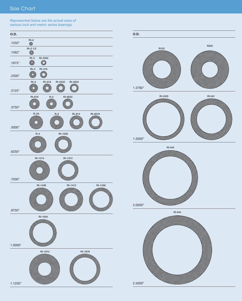
RI–2
RI–2 1/2
RI–3 RI–3332
RI–1812 RI–1878
RI–5 RI–518 RI–5532 RI–5632
R–2A R–3 RI–814 RI–8516
RI–618 R–2 RI–6632
RI–4 RI–418
R–4 RI–1038
RI–1438 RI–1412 RI–1458
RI–1214 RI–1212
RI–1634
Represented below are the actual sizes of various inch and metric series bearings.
O.D.
.1250"
.1562"
.1875"
.2500"
.3125"
.3750"
.5000"
.6250"
.7500"
.8750"
1.0000"
1.1250"
O.D.
1.3780"
1.5000”
2.0000”
2.5000”
R202R103
RI-2420
RI-544
RI-543
RI-541
66844_InCov.indd 2 11/7/12 3:13 PM

MEDICAL AND DENTAL Handpieces and Drills
Centrifuges
Diagnostic Equipment
Artificial Heart Pumps
Blood Analyzers
Cryogenic Pumps
Lasers
COMMERCIAL AND MILITARY AEROSPACEAirframe Control Systems
Auxiliary Drive Systems
Fuel/Air Valves
Aircraft Instruments
Navigation Systems
Turn Coordinators
DEFENSE Missiles
Tanks
UAVs
HIGH TECH/HIGH PERFORMANCEScanners
Semiconductor Processing
Optical Encoders
Robotics
Galvos
Microturbines
Turbomolecular Pumps
Flow Meters
ApplicationsSize Chart
i
RI–2
RI–2 1/2
RI–3 RI–3332
RI–1812 RI–1878
RI–5 RI–518 RI–5532 RI–5632
R–2A R–3 RI–814 RI–8516
RI–618 R–2 RI–6632
RI–4 RI–418
R–4 RI–1038
RI–1438 RI–1412 RI–1458
RI–1214 RI–1212
RI–1634
Represented below are the actual sizes of various inch and metric series bearings.
O.D.
.1250"
.1562"
.1875"
.2500"
.3125"
.3750"
.5000"
.6250"
.7500"
.8750"
1.0000"
1.1250"
O.D.
1.3780"
1.5000”
2.0000”
2.5000”
R202R103
RI-2420
RI-544
RI-543
RI-541
66844_InCov.indd 2 11/7/12 3:13 PM

www.nhbb.com i i
Table of Contents
Introduction
03 Precision Division
04 Precision Capabilities
06 Basic Technical Information
09 Ultra-High-Speed Bearing Designs
10 Special Designs and Assemblies
12 Part Numbering System
Miniature Inch Series
16 Radial, Open, Unflanged
17 Radial, Open, Flanged
18 Radial, Shielded, Unflanged
19 Radial, Shielded, Flanged
20 Full Ball Complement, Radial, Open, Unflanged and Flanged
21 Full Ball Complement, Radial, Shielded, Unflanged and Flanged
22 Extended Inner Ring, Radial, Open, Unflanged and Flanged
23 Extended Inner Ring, Radial, Shielded, Unflanged and Flanged
24 Modified Dimension, Radial, Open, Unflanged and Flanged
25 Modified Dimension, Radial, Shielded, Unflanged and Flanged
Custom Specialty
30 Angular Contact, Full Ball Complement
31 Angular Contact
32 Radial
Torque Tube and Thinex
36 Torque Tube, Standard Width
37 Torque Tube, Extended Inner Ring
38 Thinex
(continued other side)
66844_Text.indd 1 11/16/12 9:45 AM

www.nhbb.com i i i
Table of Contents
Metric Series
40 Middle Size Metric Series – Radial, Unflanged
41 Miniature Metric L Series – Radial, Open, Unflanged and Flanged
42 Miniature Metric L Series – Radial, Shielded, Unflanged and Flanged
43 Miniature Metric R Series – Radial, Open, Unflanged and Flanged
44 Miniature Metric R Series – Radial, Shielded, Unflanged and Flanged
Engineering
46 Engineering Services
47 Materials
49 Cages
52 Seals and Shields
53 Internal Bearing Geometry
55 Lubrication
57 Preload and Duplex Ball Bearings
58 Load Ratings and Bearing Life
61 Mounting and Coding
62 Recommended Fits
63 Tolerances
65 Torque
65 Post Service Analysis
66 Interchange Chart
68 Metric Conversion Table
69 Temperature Conversion Table
New Hampshire Ball Bearings, Inc.
72 NHBB Overview
73 Astro Division, Laconia, NH
74 HiTech Division, Peterborough, NH
75 myonic USA, Chatsworth, CA
76 Minebea Co., Ltd.
NHBB reserves the right to change specifications and other information included in this catalog without notice. All information, data, and dimension tables in this catalog have been carefully compiled and thoroughly checked. However, no responsibility for possible errors or omissions can be assumed.
66844_Text.indd 2 11/16/12 9:45 AM
www.nhbb.com 1
Introduction
Contents
03 Precision Division
04 Precision Capabilities
06 Basic Technical Information
09 Ultra-High-Speed Bearing Designs
10 Special Designs and Assemblies
12 Part Numbering System
66844_Text.indd 3 11/16/12 9:45 AM

www.nhbb.com 2
66844_Text.indd 4 11/16/12 9:45 AM

www.nhbb.com 3
Introduction
Precision Division
NHBB’s Precision Division has a longstanding commitment to cost-competitive
volume production methods for nonstandard, ultraprecision miniature and instrument
bearings as well as medium-size bearings up to 2.5 inches in outer diameter. We provide
significant technical expertise by working collaboratively with our customers throughout
the product development process. Our applications engineers incorporate design
innovations in a broad range of bearing construction types, and always leverage the
latest technologies to achieve optimal performance and customer satisfaction.
Our commitment to research and development, as demonstrated by our modern product
development and testing lab, has strengthened our ability to offer unique solutions,
especially in high speed and low torque applications. With our expanded testing
capabilities, we are able to simulate customer application parameters, which results in
bearings that last longer, perform more consistently, and run quieter. We are also proud
of several industry firsts, including our patented silver-polymer retainer, which extends
bearing life by up to 60%.
The Precision Division factory in Chatsworth, California features advanced CNC
equipment for machining and grinding, and a Class 1000 clean room where all bearing
assembly takes place. This is also the state-of-the-art location for unique lubricant
processing, functional testing, precise dimensional coding of ring components, and
laser marking.
Our commitment to excellence and our strong customer partnerships reveal a
deeper goal…Keeping Technology on the Move®.
66844_Text.indd 5 11/16/12 9:45 AM

www.nhbb.com 4
Introduction
Precision Capabilities
ENGINEERING SUPPORTExperienced sales and applications engineers
work closely with you throughout the product
development process to create customized
bearings for unique applications. We offer:
DESIGN FLEXIBILITYWorking from preliminary design concepts,
we’re able to customize bearings to meet your
specific application challenges. Our focus is to
maximize value to our customers by providing
cost-effective solutions. What makes design
flexibility possible?
coatings for extreme environments
QUALITY CERTIFICATIONSWe offer exceptional quality with an emphasis
on dimensional accuracy, process control, and
and aerospace standards, including:
66844_Text.indd 6 11/16/12 9:45 AM
www.nhbb.com 5
Introduction
Precision Capabilities
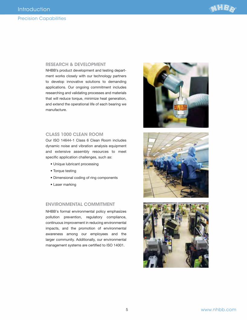
RESEARCH & DEVELOPMENTNHBB’s product development and testing depart-
ment works closely with our technology partners
to develop innovative solutions to demanding
applications. Our ongoing commitment includes
researching and validating processes and materials
that will reduce torque, minimize heat generation,
and extend the operational life of each bearing we
manufacture.
CLASS 1000 CLEAN ROOM
dynamic noise and vibration analysis equipment
and extensive assembly resources to meet
specific application challenges, such as:
ENVIRONMENTAL COMMITMENTNHBB's formal environmental policy emphasizes
pollution prevention, regulatory compliance,
continuous improvement in reducing environmental
impacts, and the promotion of environmental
awareness among our employees and the
66844_Text.indd 7 11/16/12 9:45 AM

www.nhbb.com
Ball Bearing ComponentsViewing a cross-section of a standard ball bearing can help you
select a bearing with the appropriate components for your
design or application, as it illustrates the relative position of
these components in the ball bearing assembly.
Outside Diameter(O.D.)
BearingWidth
O.D. Chamfer
Snap Ring
Stainless Steel Shield
Inner Ring Face
Outer Ring Face
Inside Diameter(BORE)
Flange
Undercut
Seal or ShieldGroove
Inner Ring
I.D. Chamfer
Inner Ring Raceway
Inner Ring Land
Stainless SteelRibbon Retainer
Outer Ring Land
Outer Ring
Outer Ring Raceway
Cross-section View of a Ball Bearing
Bearing SelectionTo ensure optimal speed and load carrying capacity, several
factors must be considered when choosing the proper bearing
for your application. These factors include ring material, design,
MaterialsMiniature and instrument bearings are normally made of either
steel for applications that require corrosion resistance and 52100
chrome steel for maximum fatigue life. These materials are heat-
treated to achieve optimum hardness and dimensional stability
and they are suitable for most applications. When more difficult
operating conditions necessitate an alternative to standard
® and nitrogen-enriched steel.
6
Radial Angular Contact
Introduction
Basic Technical Information
ROOM TEMP. HARDNESS (HRC) MATERIAL SPECIFICATION MELT ATTRIBUTES
BALLS RINGS
METHOD
quality Very low impurity level
quality
purity level
*440C stainless steel is the preferred material with the best availability.**Consumable Electrode Vacuum Melted
DesignThe design of a bearing is critical in determining its load carrying
capacity and maximum operating speed—factors which directly
impact the bearing’s operating life. Various types of bearings
have been designed to meet the operating parameters of your
application.
The radial or conrad bearing
the most popular type due to its ability to handle both radial
loads and thrust loads in either direction. This type is offered with
various seal or shield options.
The angular contact bearing is designed with a relieved shoul-
der to allow for a greater number of balls, thereby increasing its
load carrying capacity. The angular contact design also allows
for the use of a full section cage, which is desirable for high speed
applications. This type of bearing can handle thrust loads in one
direction only.
BG42® is a registered trademark of Latrobe Specialty Steel Company.
66844_Text.indd 8 11/16/12 9:45 AM

www.nhbb.com
Seals and Shields
and prevent particulate contamination from reaching critical
offer greater deterrence to particulate contamination but increase
torque and limit operating speed. NHBB offers a variety of enclo-
describes these options in greater detail.
CagesThe cage, also referred to as the retainer or separator, is the com-
ponent that separates and positions the balls at approximately
equal intervals around the bearing raceway. Proper selection of
a bearing cage is critical for meeting the load, speed, and
temperature requirements of your application.
The standard cages for radial or conrad miniature and instrument
ball bearings are stamped metal ribbon or crown. The application
-
priate for most general purpose applications. For high speed
applications, machined cages made of phenolic, polyamide-
ABEC Grade
include radial and axial runout requirements, bore and O.D. fits,
and audible noise level. The table below shows the bore and
applications.
The chart on page 63 provides a complete description of the
-
mends these grades for precision assemblies where low noise
-
tant considerations for noise sensitive applications.
7
Introduction
Basic Technical Information
One-piece Crown, Metallic, Stamped
Two-piece Ribbon, Metallic, Stamped and Crimped
One-piece Full Type, Polymer, Machined
One-piece Crown, Phenolic, Machined
RADIAL MEAN DIAMETER RUNOUT TOLERANCE
ABEC O.D. INNER OUTER BORE O.D.
GRADE SIZE RING RING
66844_Text.indd 9 11/16/12 9:45 AM
Radial Play
balls and the races with no load applied to the bearing in any
thermal expansions, the effects of interference fits, and to
suggested radial play for some typical applications.
LubricantThere are hundreds of lubricants available for ball bearings and
each has a particular characteristic that makes it suitable for a
torque is a problem, grease is preferred for prelubrication since it
is less susceptible to migration and leakage. Grease can in-
crease bearing torque by a factor of 1.2 to 5.0 depending on the
further information.
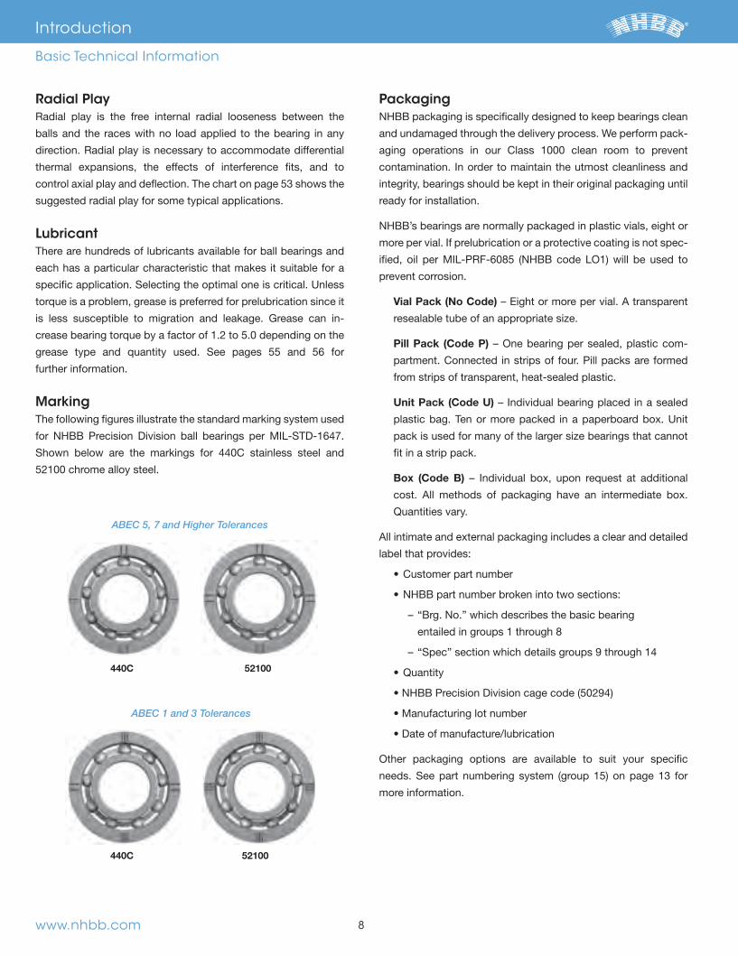
MarkingThe following figures illustrate the standard marking system used
52100 chrome alloy steel.
PackagingNHBB packaging is specifically designed to keep bearings clean
and undamaged through the delivery process. We perform pack-
aging operations in our Class 1000 clean room to prevent
integrity, bearings should be kept in their original packaging until
ready for installation.
NHBB’s bearings are normally packaged in plastic vials, eight or
-
prevent corrosion.
Vial Pack (No Code)
resealable tube of an appropriate size.
Pill Pack (Code P) – One bearing per sealed, plastic com-
partment. Connected in strips of four. Pill packs are formed
from strips of transparent, heat-sealed plastic.
Unit Pack (Code U)
pack is used for many of the larger size bearings that cannot
fit in a strip pack.
Box (Code B)
Quantities vary.
label that provides:
– “Brg. No.” which describes the basic bearing
Other packaging options are available to suit your specific
more information.
8www.nhbb.com
Introduction
Basic Technical Information
440C 52100
52100440C
ABEC 5, 7 and Higher Tolerances
ABEC 1 and 3 Tolerances
66844_Text.indd 10 11/16/12 9:45 AM

9 www.nhbb.com
Introduction
Ultra-High-Speed Bearing Designs
NHBB is recognized as the leader in the design and manufacture
of ultra-high-speed bearings, which can operate at speeds up to
500,000 rpm. This capability is based on an unwavering commit-
ment to superior product design, backed by a cutting-edge
product development and test laboratory. Our lab is dedicated to
validating new retainer materials, in addition to conducting ex-
haustive testing of new lubricants and surface treatments—all
with the goal of extending bearing operational life.
-
lutions per second, bearing components must be made from the
best materials available and manufactured to extremely tight
machined retainer made from a specialty material that provides
lubricity, lower thermal expansion, resistance to high tempera-
tures, and the option of autoclavability.
Our applications engineers work collaboratively with you to
ensure the best bearing design for your ultra-high-speed appli-
Meldin® is a registered trademark of Saint-Gobain Performance Plastics Corporation.
Torlon® is a registered trademark of Solvay Advanced Polymers, L.L.C.
Ultra-precise Tolerances* Exacting dimensional accuracy of bearing raceways
NHBB offers:
honed lands
than 0.000010 in. on average
ances—available within
0.0001 in.
better
* To specify the features referenced above,
notate “MC” in the NHBB part number.
High Quality Bearing Steel
optimal hardness and dimensional stability, low noise,
as well as economical price points
For more information about bearing steel, see page 47.
Machined Retainers
– Meldin®
– Polyamide-imide
– Patented silver coated machined Torlon® retainer—
crown or full. Extends operational life in marginally
lubricated applications and provides added benefit with
the antimicrobial properties of the silver coating
For more information on machined retainers, see pages 49
through 51.
Optimal Lubricant Type and Fill
load carrying properties, wear resistance, life, and
corrosion resistance
fill ratios
For more information about lubricants, see pages 55 and 56.
66844_Text.indd 11 11/16/12 9:45 AM

www.nhbb.com
Today’s high technology products demand increasingly sophisti-
cated bearing designs. NHBB stands ready to support your
needs with:
and assembly
Our experienced staff will help you design quality, cost-effective
next-up bearing assemblies for your specific applications —and
manufacture them in small or volume production quantities.
Below are a few examples of the unique designs and special
features we offer. They include ceramic balls, machined retainers,
anti-rotation slots, integral shields, extended rings, and custom
double row configurations. Contact us to learn more about how
we can assist you with your customization needs.
10
Special Assemblies Integral Duplex Designs
Flanged Integral Duplex Bearing with Extended Inner Ring
Double Row Miniature Cam Follower Assembly with Threaded Shaft
Integral Duplex Angular Contact Bearing
Pulley Assembly Bonded to Discrete Sealed Bearings
Bearing Pin Assembly
Pulley Assembly with Discrete Shielded and Flanged Bearings
Introduction
Special Designs and Assemblies
66844_Text.indd 12 11/16/12 9:45 AM

www.nhbb.com 11
Custom Flange with Mounting Holes
Extended Outer Ring with Flange
Custom Machined Retainer, Ceramic Balls
Integral Shield, Custom Machined Retainer, Ceramic Balls
Custom Designs
Double Row, Spherical O.D.
High Speed Dental Bearing with Integral Shield
Metric Radial Bearing with Anti-rotation Slots
Shielded Miniature Double Row Bearing Duplex Set with Matched Spacers
End Cap for Gyro Application
Double Row, Full Ball Complement
High Speed Angular Contact Bearingwith Custom Machined Retainer
Introduction
Special Designs and Assemblies
66844_Text.indd 13 11/16/12 9:45 AM
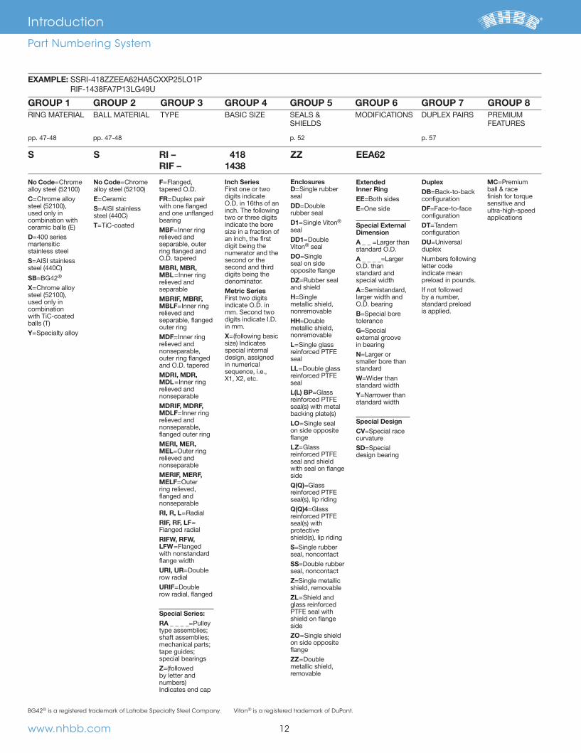
No Code=Chrome
C=Chrome alloy
used only in combination with
D= martensitic stainless steel S=
SB= ®
X=Chrome alloy
used only in combination with TiC-coated
Y=
No Code=Chrome
E=Ceramic S=
T=TiC-coated
F=Flanged, tapered O.D.FR=Duplex pair with one flanged and one unflanged bearingMBF=relieved and separable, outer ring flanged and O.D. taperedMBRI, MBR, MBL=relieved and separableMBRIF, MBRF, MBLF=relieved and separable, flanged outer ringMDF=relieved and nonseparable, outer ring flanged and O.D. taperedMDRI, MDR, MDL=relieved and nonseparableMDRIF, MDRF, MDLF=relieved and nonseparable, flanged outer ringMERI, MER, MEL=Outer ring relieved and nonseparableMERIF, MERF, MELF=Outer ring relieved, flanged and nonseparableRI, R, L=RIF, RF, LF= Flanged radialRIFW, RFW, LFW=Flanged with nonstandard flange widthURI, UR=Double row radialURIF=Double row radial, flanged Special Series:RA _ _ _ _=Pulley
special bearingsZ by letter and
Inch Series First one or two digits indicate O.D. in 16ths of an inch. The following two or three digits indicate the bore size in a fraction of an inch, the first digit being the numerator and the second or the second and third digits being the denominator.Metric Series First two digits indicate O.D. in
in mm.X=
special internal design, assigned in numerical sequence, i.e., X1, X2, etc.
Enclosures D=sealDD=Double rubber sealD1= ® sealDD1=Double Viton® sealDO seal on side opposite flangeDZand shieldH metallic shield, nonremovableHH=Double metallic shield, nonremovableL= reinforced PTFE sealLL=Double glass reinforced PTFE sealL(L) BP=Glass reinforced PTFE
LO= on side opposite flangeLZ=Glass reinforced PTFE seal and shield with seal on flange sideQ(Q)=Glass reinforced PTFE
Q(Q)4=Glass reinforced PTFE
protective
S seal, noncontactSS=Double rubber seal, noncontactZshield, removableZL=glass reinforced PTFE seal with shield on flange sideZO=on side opposite flangeZZ=Double metallic shield, removable
Extended Inner RingEE=Both sidesE=One side
Special External DimensionA _ _ standard O.D.A _ _ _ _O.D. than standard and special widthAlarger width and O.D. bearingB toleranceG external groove in bearingN smaller bore than standardW=Wider than standard widthY=Narrower than standard width
Special DesignCV curvatureSDdesign bearing
DuplexDB=Back-to-back configurationDF=Face-to-face configurationDT=Tandem configurationDUduplexNumbers following letter code indicate mean preload in pounds.
by a number, standard preload is applied.
MC=Premium ball & race finish for torque sensitive and ultra-high-speed applications
EXAMPLE:
S S RI – RIF –
4181438
ZZ EEA62
GROUP 1 GROUP 2 GROUP 3 GROUP 4 GROUP 5 GROUP 6 GROUP 7 GROUP 8
12www.nhbb.com
Introduction
Part Numbering System
BG42® is a registered trademark of Latrobe Specialty Steel Company. Viton® is a registered trademark of DuPont.
66844_Text.indd 14 11/16/12 9:45 AM
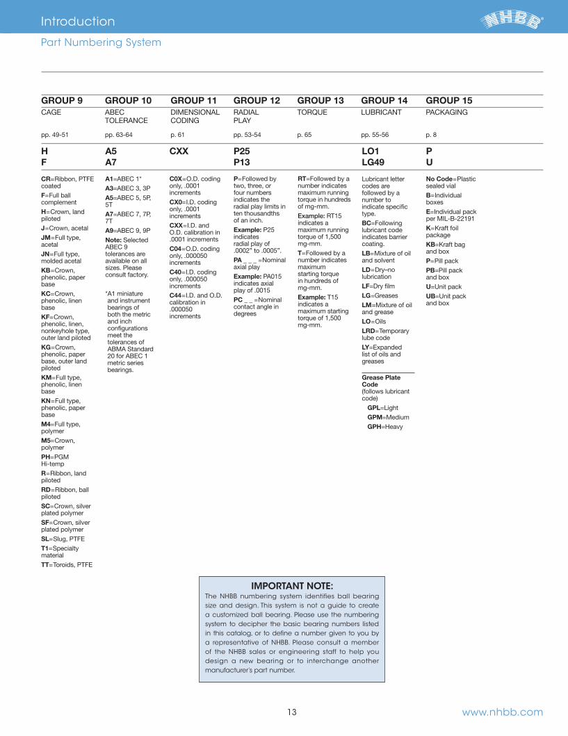
IMPORTANT NOTE:The NHBB numbering system identifies ball bearing size and design. This system is not a guide to create a customized ball bearing. Please use the numbering system to decipher the basic bearing numbers listed in this catalog, or to define a number given to you by a representative of NHBB. Please consult a member of the NHBB sales or engineering staff to help you design a new bearing or to interchange another manufacturer’s part number.
HF
A5A7
CXX P25P13
LO1LG49
PU
13
GROUP 9 GROUP 10 GROUP 11 GROUP 12 GROUP 13 GROUP 14 GROUP 15
www.nhbb.com
CR=coatedF=Full ball complementH=Crown, land pilotedJ=Crown, acetalJM=Full type, acetalJN=Full type, molded acetalKB=Crown, phenolic, paper baseKC=Crown, phenolic, linen baseKF=Crown, phenolic, linen, nonkeyhole type, outer land pilotedKG=Crown, phenolic, paper base, outer land pilotedKM=Full type, phenolic, linen baseKN=Full type, phenolic, paper baseM4=Full type, polymerM5=Crown, polymerPH=PGM Hi-tempR= pilotedRD= pilotedSC=Crown, silver plated polymerSF=Crown, silver plated polymerSL=T1=materialTT=Toroids, PTFE
A1A3A55TA7
A9Note:
tolerances are available on all sizes. Please consult factory.
and instrument bearings of both the metric and inch configurations meet the tolerances of
metric series bearings.
C0X=O.D. coding only, .0001 incrementsCX0=only, .0001 incrementsCXX=O.D. calibration in .0001 incrementsC04=O.D. coding only, .000050 incrementsC40=only, .000050 incrementsC44=calibration in .000050 increments
P=Followed by two, three, or four numbers indicates the radial play limits in ten thousandths of an inch.Example: P25 indicates radial play of .0002” to .0005”.PA _ _ _ =Nominal axial playExample:indicates axial play of .0015PC _ _ =Nominal contact angle in degrees
RT=Followed by a number indicates maximum running torque in hundreds of mg-mm.Example: indicates a maximum running torque of 1,500 mg-mm.T=Followed by a number indicates maximum starting torque in hundreds of mg-mm.Example: T15 indicates a maximum starting torque of 1,500 mg-mm.
codes are followed by a number to indicate specific type.BC=Following lubricant code indicates barrier coating.LB=Mixture of oil and solventLD=Dry–no lubricationLF=Dry filmLG=Greases LM=Mixture of oil and greaseLO=OilsLRD=Temporary lube codeLY=Expanded list of oils and greases
Grease Plate Code
GPLGPM=MediumGPH=Heavy
No Code=Plastic sealed vialB=boxesE
K=Kraft foil packageKB=Kraft bag and boxP=Pill packPB=Pill pack and boxUUB and box
Introduction
Part Numbering System
66844_Text.indd 15 11/16/12 9:45 AM

www.nhbb.com 14
66844_Text.indd 16 11/16/12 9:45 AM

www.nhbb.com 15
Miniature Inch Series
Contents
16 Radial, Open, Unflanged
17 Radial, Open, Flanged
18 Radial, Shielded, Unflanged
19 Radial, Shielded, Flanged
20 Full Ball Complement, Radial, Open, Unflanged and Flanged
21 Full Ball Complement, Radial, Shielded, Unflanged and Flanged
22 Extended Inner Ring, Radial, Open, Unflanged and Flanged
23 Extended Inner Ring, Radial, Shielded, Unflanged and Flanged
24 Modified Dimension, Radial, Open, Unflanged and Flanged
25 Modified Dimension, Radial, Shielded, Unflanged and Flanged
66844_Text.indd 17 11/16/12 9:45 AM

www.nhbb.com
.0400 1.016 .1250 .0469
.0469 .1562 .0625
.0550 .1875 .0781
.0781 .2500 6.350 .0937
.0937 .1875 .0625
.0937 .1875 .0625
.0937 .3125 .1094
.1250 .2500 6.350 .0937
.1250 .2500 6.350 .0937
.1250 .3125 .1094
.1250 .3750 .1094
.1250 .3750 .1562
.1250 .5000 .1719
.1562 .3125 .1094
.1562 .3125 .1094
.1875 .3125 .1094
.1875 .3125 .1094
.1875 .3750 .1250
.1875 .5000 .1562
.2500 6.350 .3750 .1250
.2500 6.350 .5000 .1250
.2500 6.350 .6250 .1960
.2500 6.350 .7500 .2188
.3125 .5000 .1562
.3750 .6250 .1562
.3750 .8750 22.225 .2188
.5000 .8750 22.225 .2188
.5000 1.1250 .2500
.6250 1.3750 .2812♦ .7500 1.6250 .3125♦ .8750 22.225 1.8750 .3750
r
r
Lo d DLi
BRibbon Cage
r
r
Lo d DLi
B
CAGE BORE O.D. WIDTH
LAND DIAMETER
BALL LOAD RATINGS** TYPE
d D B
(REFERENCE) FILLET COMPLEMENT LB. BRG.
BASIC P/N * RADIUS NO. SIZE DYN. STATIC WT. RIBBON CROWN INCH (mm)◊ INCH (mm) INCH (mm)◊ Li Lo r Z Db C Co GMS. ▼
Notes: 1. Inch to metric conversion—see page 68. 2. Basic part numbers shown above include
code “SS” for AISI 440C stainless steel. If SAE 52100 chrome alloy steel is desired, delete "SS."
3. See page 63 for ABEC tolerances. 4. r=Maximum shaft or housing fillet radius that
bearing corners will clear. 5. Open bearings may or may not have shield
grooves (detail not shown in the above draw-ings). Consult the factory for reference infor-mation regarding the shield recess diameter.
* “R” Ribbon or “H” Crown cages are available as indicated. Please consult with factory for machined cage availability.
◊ Metric dimensions are for reference only.
** Load ratings are based on ABMA Standard #12.
♦ Limited retainer options available. Please consult with factory.
▼ Bearing weights are for reference only.
Crown Cage
Miniature Inch Series
Radial, Open, Unflanged
16
66844_Text.indd 18 11/16/12 9:45 AM

www.nhbb.com
.0400 1.016 .1250 .0469
.0469 .1562 .0625
.0550 .1875 .0781
.0781 .2500 6.350 .0937
.0937 .1875 .0625
.0937 .1875 .0625
.0937 .3125 .1094
.1250 .2500 6.350 .0937
.1250 .2500 6.350 .0937
.1250 .3125 .1094
.1250 .3750 .1094
.1250 .3750 .1562
.1562 .3125 .1094
.1562 .3125 .1094
.1875 .3125 .1094
.1875 .3125 .1094
.1875 .3750 .1250
.1875 .5000 .1562
.2500 6.350 .3750 .1250
.2500 6.350 .5000 .1250
.2500 6.350 .6250 .1960
.3125 .5000 .1562
.3750 .8750 22.225 .2812
.5000 1.1250 .2500
r
BfB
DfLoD Li d
r
LoL di
B
r
fDD
r
Bf
Notes: 1. Inch to metric conversion—see page 68. 2. Basic part numbers shown above include
code “SS” for AISI 440C stainless steel. If SAE 52100 chrome alloy steel is desired, delete "SS."
3. See page 63 for ABEC tolerances. 4. r=Maximum shaft or housing fillet radius that
bearing corners will clear. 5. Open bearings may or may not have shield
grooves (detail not shown in the above draw-ings). Consult the factory for reference infor-mation regarding the shield recess diameter.
* “R” Ribbon or “H” Crown cages are available as indicated. Please consult with factory for machined cage availability.
◊ Metric dimensions are for reference only.
** Load ratings are based on ABMA Standard #12.
▼ Bearing weights are for reference only.
Ribbon Cage Crown Cage
CAGE LAND DIAMETER
BALL LOAD RATINGS** TYPE BORE O.D. WIDTH FLANGE FLANGE
(REFERENCE) FILLET COMPLEMENT LB. BRG.
BASIC P/N * d D B DIA. WIDTH RADIUS NO. SIZE DYN. STATIC WT. RIBBON CROWN INCH (mm)◊ INCH (mm)◊ INCH (mm)◊ Df Bf Li Lo r Z Db C Co GMS. ▼
Miniature Inch Series
Radial, Open, Flanged
17
66844_Text.indd 19 11/16/12 9:45 AM
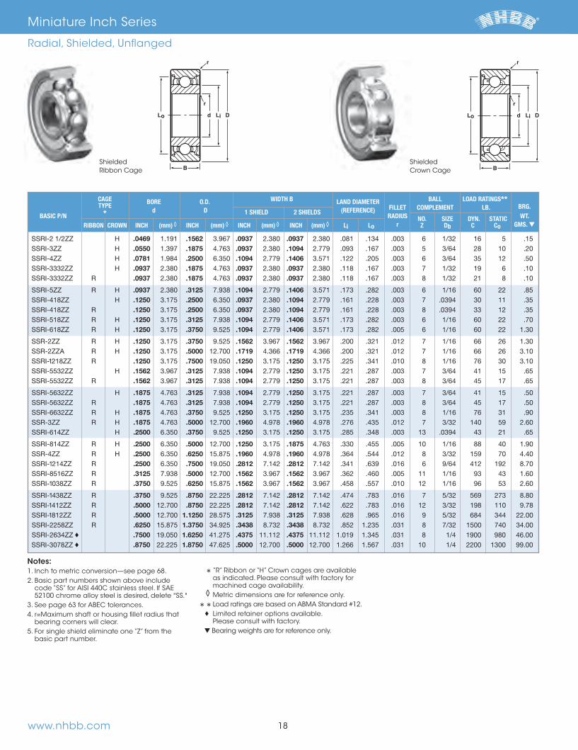
www.nhbb.com
.0469 .1562 .0937 .0937
.0550 .1875 .0937 .1094
.0781 .2500 6.350 .1094 .1406
.0937 .1875 .0937 .0937
.0937 .1875 .0937 .0937
.0937 .3125 .1094 .1406
.1250 .2500 6.350 .0937 .1094
.1250 .2500 6.350 .0937 .1094
.1250 .3125 .1094 .1406
.1250 .3750 .1094 .1406
.1250 .3750 .1562 .1562
.1250 .5000 .1719 .1719
.1250 .7500 .1250 .1250
.1562 .3125 .1094 .1250
.1562 .3125 .1094 .1250
.1875 .3125 .1094 .1250
.1875 .3125 .1094 .1250
.1875 .3750 .1250 .1250
.1875 .5000 .1960 .1960
.2500 6.350 .3750 .1250 .1250
.2500 6.350 .5000 .1250 .1875
.2500 6.350 .6250 .1960 .1960
.2500 6.350 .7500 .2812 .2812
.3125 .5000 .1562 .1562
.3750 .6250 .1562 .1562
.3750 .8750 22.225 .2812 .2812
.5000 .8750 22.225 .2812 .2812
.5000 1.1250 .3125 .3125
.6250 1.3750 .3438 .3438 ♦ .7500 1.6250 .4375 11.112 .4375♦ .8750 22.225 1.8750 .5000 .5000
ShieldedRibbon Cage
r
r
Lo d DLi
B
r
r
Lo d DLi
B
CAGE BORE O.D. WIDTH B LAND DIAMETER BALL LOAD RATINGS** TYPE d D 1 SHIELD 2 SHIELDS (REFERENCE) FILLET COMPLEMENT LB. BRG. BASIC P/N * RADIUS NO. SIZE DYN. STATIC WT. RIBBON CROWN INCH (mm)◊ INCH (mm)◊ INCH (mm)◊ INCH (mm)◊ Li Lo r Z Db C Co GMS. ▼
Notes: 1. Inch to metric conversion—see page 68. 2. Basic part numbers shown above include
code “SS” for AISI 440C stainless steel. If SAE 52100 chrome alloy steel is desired, delete "SS."
3. See page 63 for ABEC tolerances. 4. r=Maximum shaft or housing fillet radius that
bearing corners will clear. 5. For single shield eliminate one “Z” from the
basic part number.
* “R” Ribbon or “H” Crown cages are available as indicated. Please consult with factory for machined cage availability.
◊ Metric dimensions are for reference only.
** Load ratings are based on ABMA Standard #12.
♦ Limited retainer options available. Please consult with factory.
▼ Bearing weights are for reference only.
Miniature Inch Series
Radial, Shielded, Unflanged
18
Shielded Crown Cage
66844_Text.indd 20 11/16/12 9:45 AM
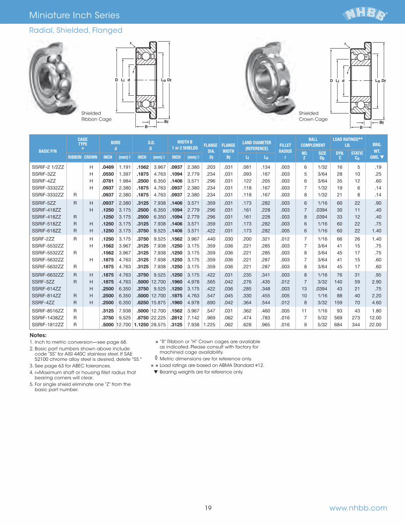
www.nhbb.com
.0469 .1562 .0937
.0550 .1875 .1094
.0781 .2500 6.350 .1406
.0937 .1875 .0937
.0937 .1875 .0937
.0937 .3125 .1406
.1250 .2500 6.350 .1094
.1250 .2500 6.350 .1094
.1250 .3125 .1406
.1250 .3750 .1406
.1250 .3750 .1562
.1562 .3125 .1250
.1562 .3125 .1250
.1875 .3125 .1250
.1875 .3125 .1250
.1875 .3750 .1250
.1875 .5000 .1960
.2500 6.350 .3750 .1250
.2500 6.350 .5000 .1875
.2500 6.350 .6250 .1960
.3125 .5000 .1562
.3750 .8750 22.225 .2812
.5000 1.1250 .3125
r
Df
r
D d LoLi
BfB
Df
r
LoD dLi
BfB
r
CAGE WIDTH B LAND DIAMETER
BALL LOAD RATINGS** TYPE BORE O.D.
1 or 2 SHIELDS FLANGE FLANGE (REFERENCE)
FILLET COMPLEMENT LB. BRG. BASIC P/N * d D DIA. WIDTH RADIUS NO. SIZE DYN. STATIC WT. RIBBON CROWN INCH (mm)◊ INCH (mm)◊ INCH (mm)◊ Df Bf Li Lo r Z Db C Co GMS. ▼
Notes: 1. Inch to metric conversion—see page 68. 2. Basic part numbers shown above include
code “SS” for AISI 440C stainless steel. If SAE 52100 chrome alloy steel is desired, delete "SS."
3. See page 63 for ABEC tolerances. 4. r=Maximum shaft or housing fillet radius that
bearing corners will clear. 5. For single shield eliminate one “Z” from the
basic part number.
* “R” Ribbon or “H” Crown cages are available as indicated. Please consult with factory for machined cage availability.
◊ Metric dimensions are for reference only.
** Load ratings are based on ABMA Standard #12.
▼ Bearing weights are for reference only.
ShieldedRibbon Cage
Miniature Inch Series
Radial, Shielded, Flanged
19
ShieldedCrown Cage
66844_Text.indd 21 11/16/12 9:45 AM
www.nhbb.com
.0469 .1562 .0625
.0550 .1875 .0781
.0781 .2362 6.000 .0937
.0781 .2500 6.350 .0937
.0937 .1875 .0625
.0937 .3125 .1094
.1250 .2500 6.350 .0937
.1250 .3125 .1094
.1250 .3750 .1094
.1250 .3750 .1562
.1562 .3125 .1094
.1875 .3125 .1094
.1875 .3750 .1250
.1875 .5000 .1562
.2500 6.350 .3750 .1250
.2500 6.350 .5000 .1250
.2500 6.350 .6250 .1960
.2500 6.350 .7500 .2188
.3125 .5000 .1562
.3750 .8750 22.225 .2188
.5000 .8750 22.225 .2188
Unflanged Flanged
r
r
Lo d DLi
B
LAND DIAMETER
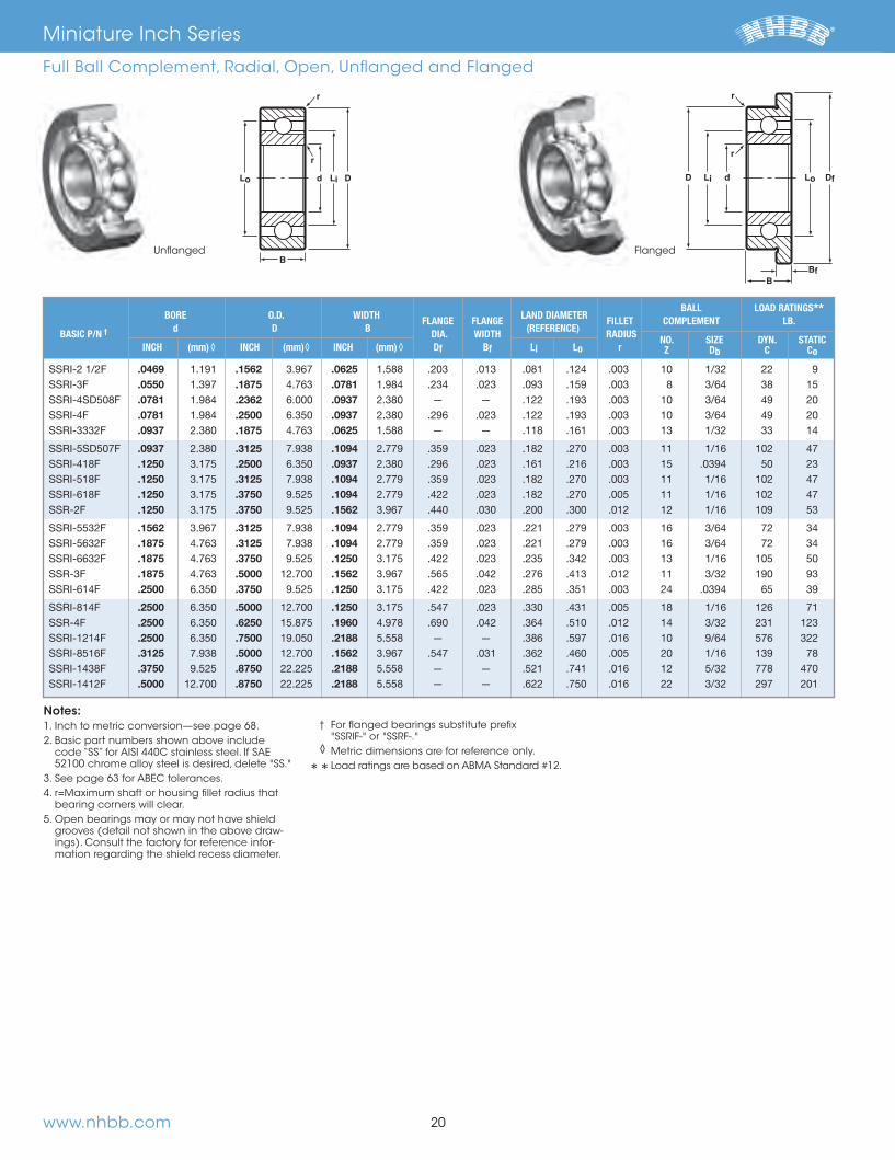
BALL LOAD RATINGS** BORE O.D. WIDTH FLANGE FLANGE
(REFERENCE) FILLET COMPLEMENT LB.
BASIC P/N † d D B DIA. WIDTH RADIUS NO. SIZE DYN. STATIC INCH (mm)◊ INCH (mm)◊ INCH (mm)◊ Df Bf Li Lo r Z Db C Co
Notes: 1. Inch to metric conversion—see page 68. 2. Basic part numbers shown above include
code “SS” for AISI 440C stainless steel. If SAE 52100 chrome alloy steel is desired, delete "SS."
3. See page 63 for ABEC tolerances. 4. r=Maximum shaft or housing fillet radius that
bearing corners will clear. 5. Open bearings may or may not have shield
grooves (detail not shown in the above draw-ings). Consult the factory for reference infor-mation regarding the shield recess diameter.
† For flanged bearings substitute prefix "SSRIF-" or "SSRF-."
◊ Metric dimensions are for reference only.
** Load ratings are based on ABMA Standard #12.
Miniature Inch Series
Full Ball Complement, Radial, Open, Unflanged and Flanged
20
66844_Text.indd 22 11/16/12 9:45 AM

www.nhbb.com
.0469 .1562 .0937
.0550 .1875 .1094
.0781 .2500 6.350 .1406
.0937 .1875 .0937
.0937 .3125 .1406
.1250 .2500 6.350 .1094
.1250 .3125 .1406
.1250 .3750 .1406
.1250 .3750 .1562
.1562 .3125 .1250
.1875 .3125 .1250
.1875 .3750 .1250
.1875 .5000 .1960
.2500 6.350 .3750 .1250
.2500 6.350 .5000 .1875
.2500 6.350 .6250 .1960
.2500 6.350 .7500 .2812
.3125 .5000 .1562
.3750 .8750 22.225 .2812
.5000 .8750 22.225 .2812
r
Lo d DLi
B
r
D d Df
r
LoLi
BfB
r
LAND DIAMETER
BALL LOAD RATINGS** BORE O.D. WIDTH FLANGE FLANGE
(REFERENCE) FILLET COMPLEMENT LB.
BASIC P/N † d D B DIA. WIDTH RADIUS NO. SIZE DYN. STATIC INCH (mm)◊ INCH (mm)◊ INCH (mm)◊ Df Bf Li Lo r Z Db C Co
Notes: 1. Inch to metric conversion—see page 68. 2. Basic part numbers shown above include
code “SS” for AISI 440C stainless steel. If SAE 52100 chrome alloy steel is desired, delete "SS."
3. See page 63 for ABEC tolerances. 4. r=Maximum shaft or housing fillet radius that
bearing corners will clear. 5. For single shield eliminate one “Z” from the
basic part number.
† For flanged bearings substitute prefix "SSRIF-" or "SSRF-."
◊ Metric dimensions are for reference only.
** Load ratings are based on ABMA Standard #12.
UnflangedShielded
FlangedShielded
21
Miniature Inch Series
Full Ball Complement, Radial, Shielded, Unflanged and Flanged
66844_Text.indd 23 11/16/12 9:45 AM

www.nhbb.com
.0400 1.016 .1250 .0781 .0469
.0469 .1562 .0937 .0625
.0550 .1875 .1094 .0781
.0781 .2500 6.350 .1250 .0937
.0937 .1875 .0937 .0625
.0937 .1875 .0937 .0625
.0937 .3125 .1406 .1094
.1250 .2500 6.350 .1250 .0937
.1250 .2500 6.350 .1250 .0937
.1250 .3125 .1406 .1094
.1250 .3750 .1406 .1094
.1250 .3750 .1875 .1562
.1562 .3125 .1406 .1094
.1562 .3125 .1406 .1094
.1875 .3125 .1406 .1094
.1875 .3125 .1406 .1094
.1875 .3750 .1562 .1250
.2500 6.350 .3750 .1562 .1250
.2500 6.350 .5000 .1562 .1250
.3125 .5000 .1875 .1562
UnflangedRibbon Cage
r
d DLiLo
BoBi
r
r
D dLi Lo
BfBoBi
Df
r
BORE O.D. INNER WIDTH OUTER WIDTH LAND DIAMETER BALL LOAD RATINGS** CAGE d D Bi Bo FLANGE FLANGE (REFERENCE) FILLET COMPLEMENT LB. BASIC P/N † TYPE DIA. WIDTH RADIUS NO. SIZE DYN. STATIC * INCH (mm)◊ INCH (mm)◊ INCH (mm)◊ INCH (mm)◊ Df Bf Li Lo r Z Db C Co
Notes: 1. Inch to metric conversion—see page 68. 2. Basic part numbers shown above include
code “SS” for AISI 440C stainless steel. If SAE 52100 chrome alloy steel is desired, delete "SS."
3. See page 63 for ABEC tolerances. 4. r=Maximum shaft or housing fillet radius that
bearing corners will clear. 5. Open bearings may or may not have shield
grooves (detail not shown in the above draw-ings). Consult the factory for reference infor-mation regarding the shield recess diameter.
† For flanged bearings substitute prefix "SSRIF-" or "SSRF-."
* “R” Ribbon or “H” Crown cages are available as indicated. Please consult with factory for machined cage availability.
◊ Metric dimensions are for reference only.
** Load ratings are based on ABMA Standard #12.
FlangedRibbon Cage
Miniature Inch Series
Extended Inner Ring, Radial, Open, Unflanged and Flanged
22
66844_Text.indd 24 11/16/12 9:45 AM

www.nhbb.com
.0469 .1562 .1250 .0937
.0550 .1875 .1406 .1094
.0781 .2500 6.350 .1719 .1406
.0937 .1875 .1250 .0937
.0937 .1875 .1250 .0937
.0937 .3125 .1719 .1406
.1250 .2500 6.350 .1406 .1094
.1250 .2500 6.350 .1406 .1094
.1250 .3125 .1719 .1406
.1250 .3750 .1719 .1406
.1250 .3750 .1875 .1562
.1562 .3125 .1562 .1250
.1562 .3125 .1562 .1250
.1875 .3125 .1562 .1250
.1875 .3125 .1562 .1250
.1875 .3750 .1562 .1250
.1875 .5000 .2272 .1960
.2500 6.350 .3750 .1562 .1250
.2500 6.350 .5000 .2188 .1875
.2500 6.350 .6250 .2260 .1960
.3125 .5000 .1875 .1562
BORE O.D. INNER WIDTH OUTER WIDTH LAND DIAMETER BALL LOAD RATINGS** CAGE d D Bi Bo FLANGE FLANGE (REFERENCE) FILLET COMPLEMENT LB. BASIC P/N † TYPE DIA. WIDTH RADIUS NO. SIZE DYN. STATIC * INCH (mm)◊ INCH (mm)◊ INCH (mm)◊ INCH (mm)◊ Df Bf Li Lo r Z Db C Co
Notes: 1. Inch to metric conversion—see page 68. 2. Basic part numbers shown above include
code “SS” for AISI 440C stainless steel. If SAE 52100 chrome alloy steel is desired, delete "SS."
3. See page 63 for ABEC tolerances. 4. r=Maximum shaft or housing fillet radius that
bearing corners will clear. 5. For single shield eliminate one “Z” from the
basic part number.
† For flanged bearings substitute prefix "SSRIF-" or "SSRF-."
* “R” Ribbon or “H” Crown cages are available as indicated. Please consult with factory for machined cage availability.
◊ Metric dimensions are for reference only.
** Load ratings are based on ABMA Standard #12.
FlangedShieldedRibbon Cage
Unflanged ShieldedRibbon Cage
r
d DLi
BoBi
Lo
r
r
D dLi Lo
BfBoBi
Df
r
Miniature Inch Series
Extended Inner Ring, Radial, Shielded, Unflanged and Flanged
23
66844_Text.indd 25 11/16/12 9:45 AM
www.nhbb.com
▲ H .0400 1.016 .1250 .0469 ▲ .0781 .1875 .0625
▲ .0781 .2500 6.350 .0625 .0925 2.350 .1875 .0625 .0937 .3125 .0625
.0937 .3125 .0625
.0937 .4250 .0937
.0937 .4250 .0937
.0937 .4500 .1094
.0947 .2500 6.350 .0937
.0947 .2500 6.350 .0937
.1250 .2188 .0937
.1250 .2500 6.350 .0625 ▲ .1250 .3125 .1094
.1250 .3125 .0937
.1250 .3750 .0650▲ H .1250 .3750 .1094
.1250 .4100 .1094
.1250 .4500 .1094
.1250 .5000 .1094
▲ H .1562 .4100 .1094▲ .1562 .4100 .1094
.1875 .5000 .3125
.2500 6.350 .3750 .1094 ▲ .2500 6.350 .5000 .1250
.3750 .6250 .1250 ▲ .3750 .8750 22.225 .2188
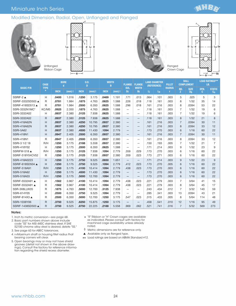
BORE O.D. WIDTH LAND DIAMETER BALL LOAD RATINGS** CAGE d D B FLANGE FLANGE (REFERENCE) FILLET COMPLEMENT LB. BASIC P/N TYPE DIA. WIDTH RADIUS NO. SIZE DYN. STATIC * INCH (mm)◊ INCH (mm)◊ INCH (mm)◊ Df Bf Li Lo r Z Db C Co
1. Inch to metric conversion—see page 68. 2. Basic part numbers shown above include
code “SS” for AISI 440C stainless steel. If SAE 52100 chrome alloy steel is desired, delete "SS."
3. See page 63 for ABEC tolerances. 4. r=Maximum shaft or housing fillet radius that
bearing corners will clear. 5. Open bearings may or may not have shield
grooves (detail not shown in the above draw-ings). Consult the factory for reference informa-tion regarding the shield recess diameter.
“R” Ribbon or “H” Crown cages are available as indicated. Please consult with factory for machined cage availability unless already noted.
◊ Metric dimensions are for reference only. ▲ Available only as flanged type. Load ratings are based on ABMA Standard #12.
Notes:
r
rLo d DLi
B
UnflangedRibbon Cage
FlangedCrown Cage
Miniature Inch Series
Modified Dimension, Radial, Open, Unflanged and Flanged
24
Df
r
LodLD i
BfB
r
66844_Text.indd 26 11/16/12 9:45 AM
www.nhbb.com
.0469 .1875 .0937 ▲ .0781 .2500 6.350 — — .0937
.0781 .2500 6.350 — — .1094
.0800 2.032 .2500 6.350 .1094
.0902 .3125 .1094
.0932 .1875 .0937
.0937 .2500 6.350 .0937
.0937 .2500 6.350 — — .1094
.0937 .2500 6.350 .0937
.0937 .2500 6.350 — — .1094
.0937 .2500 6.350 — — .0937
.0937 .2750 .0625
.0937 .2883 .0625
.0937 .4100 .1094
.0937 .4100 .1094
.1250 .2500 6.350 — — .0937
.1250 .2500 6.350 .1094
.1250 .2500 6.350 .1094
.1250 .3125 .1094
.1250 .3750 .0937
.1250 .3750 .0937
.1250 .3750 .1094 ▲ .1250 .3750 .1406
.1250 .4100 .0937
.1250 .4100 .0937
.1250 .4100 .1094
.1250 .4250 .0937
.1250 .4250 .1094
.1250 .4250 .0937
.1250 .4250 .1094
.1250 .4250 .1094
.1250 .4375 11.113 .0937
.1250 .4375 11.113 — — .0937
.1250 .5000 .1094
.1250 .5000 .1562
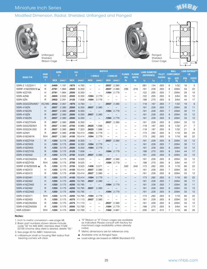
BORE O.D. WIDTH B LAND DIAMETER BALL LOAD RATINGS** CAGE d D 1 SHIELD 2 SHIELDS
FLANGE FLANGE (REFERENCE) FILLET COMPLEMENT LB. BASIC P/N TYPE DIA. WIDTH RADIUS NO. SIZE DYN. STATIC * INCH (mm)◊ INCH (mm)◊ INCH (mm)◊ INCH (mm)◊ Df Bf Li Lo r Z Db C Co
1. Inch to metric conversion—see page 68. 2. Basic part numbers shown above include
code “SS” for AISI 440C stainless steel. If SAE 52100 chrome alloy steel is desired, delete "SS."
3. See page 63 for ABEC tolerances. 4. r=Maximum shaft or housing fillet radius that
bearing corners will clear.
“R” Ribbon or “H” Crown cages are available as indicated. Please consult with factory for machined cage availability unless already noted.
◊ Metric dimensions are for reference only. ▲ Available only as flanged type. Load ratings are based on ABMA Standard #12.
Notes:
FlangedShieldedCrown Cage
Unflanged ShieldedRibbon Cage
r
rLo d DLi
B
Df
r
LoD dLi
BfB
r
Miniature Inch Series
Modified Dimension, Radial, Shielded, Unflanged and Flanged
25
66844_Text.indd 27 11/16/12 9:45 AM

www.nhbb.com
.1250 .5000 .1250 ▲ H .1250 .5000 .1250
.1250 .5769 .1250
.1250 .7500 .1250
.1562 .3750 .1562
.1567 .3750 .1250
.1567 .3750 .1562
.1875 .3125 .1094
.1875 .3125 .1094 ▲ .1875 .3125 .1250
.1875 .3750 .1094
.1875 .3750 .1094
.1875 .3750 .1094
.1875 .4100 .1094
.1875 .4100 .1094
.1875 .4250 .1250
.1875 .4250 .1094
.1875 .4250 .1250
.1875 .4375 11.113 — — .1094
.1875 .4600 .1094
.1875 .5000 .1094
.1875 .5000 .1250
.1875 .5000 .1250
.1875 .5000 .1562
.1875 .5000 .1562
.1875 .5000 .1562 ▲ H .1875 .5000 .1250
.1875 .6250 .1960
.1875 .7435 .1960
.1875 .7500 .1960
.1875 .7717 .1960
.1875 .8750 22.225 — — .1960
.1875 .5000 .3125
.2500 6.350 .4375 11.113 — — .1250
.2500 6.350 .5000 .1094
BORE O.D. WIDTH B LAND DIAMETER BALL LOAD RATINGS** CAGE d D 1 SHIELD 2 SHIELDS
FLANGE FLANGE (REFERENCE) FILLET COMPLEMENT LB. BASIC P/N TYPE DIA. WIDTH RADIUS NO. SIZE DYN. STATIC * INCH (mm)◊ INCH (mm)◊ INCH (mm)◊ INCH (mm)◊ Df Bf Li Lo r Z Db C Co
1. Inch to metric conversion—see page 68. 2. Basic part numbers shown above include
code “SS” for AISI 440C stainless steel. If SAE 52100 chrome alloy steel is desired, delete "SS."
3. See page 63 for ABEC tolerances. 4. r=Maximum shaft or housing fillet radius that
bearing corners will clear.
“R” Ribbon or “H” Crown cages are available as indicated. Please consult with factory for machined cage availability.
◊ Metric dimensions are for reference only. ▲ Available only as flanged type. Load ratings are based on ABMA Standard #12.
Notes:
FlangedShieldedCrown Cage
Unflanged ShieldedRibbon Cage
r
rLo d DLi
B
Df
r
LoD dLi
BfB
r
Miniature Inch Series
Modified Dimension, Radial, Shielded, Unflanged and Flanged (continued)
26
66844_Text.indd 28 11/16/12 9:45 AM

www.nhbb.com
.2500 6.350 .5000 .1562 .2500 6.350 .5000 .1562
.2500 6.350 .7500 .1960
.2500 6.350 .8685 22.060 — — .1960
.2500 6.350 1.0415 .1960
.2500 6.350 .6250 .3120
.2500 6.350 .7050 .1960 7.000 22.000 10.312
.3125 .6250 .1562 8.000 22.000 10.312 8.000 22.000 12.000
.3750 1.0000 .2812
BORE O.D. WIDTH B LAND DIAMETER BALL LOAD RATINGS** CAGE d D 1 SHIELD 2 SHIELDS
FLANGE FLANGE (REFERENCE) FILLET COMPLEMENT LB. BASIC P/N TYPE DIA. WIDTH RADIUS NO. SIZE DYN. STATIC * INCH (mm)◊ INCH (mm)◊ INCH (mm)◊ INCH (mm)◊ Df Bf Li Lo r Z Db C Co
www.nhbb.com
1. Inch to metric conversion—see page 68. 2. Basic part numbers shown above include
code “SS” for AISI 440C stainless steel. If SAE 52100 chrome alloy steel is desired, delete "SS."
3. See page 63 for ABEC tolerances. 4. r=Maximum shaft or housing fillet radius that
bearing corners will clear.
“R” Ribbon or “H” Crown cages are available as indicated. Please consult with factory for machined cage availability.
◊ Metric dimensions are for reference only. Load ratings are based on ABMA Standard #12.
Notes:
FlangedShieldedCrown Cage
Unflanged ShieldedRibbon Cage
r
rLo d DLi
B
Df
r
LoD dLi
BfB
r
Miniature Inch Series
Modified Dimension, Radial, Shielded, Unflanged and Flanged (continued)
27
66844_Text.indd 29 11/16/12 9:45 AM

www.nhbb.com 28
66844_Text.indd 30 11/16/12 9:45 AM

www.nhbb.com
30 Angular Contact, Full Ball Complement
31 Angular Contact
32 Radial
Custom Specialty
Contents
29
66844_Text.indd 31 11/16/12 9:45 AM

www.nhbb.com 30
Inner Ring Relieved
r
r
Ld Di
B
Lo
Notes: 1. Inch to metric conversion—see page 68. 2. See page 63 for ABEC tolerances. 3. r=Maximum shaft or housing fillet radius that
bearing corners will clear. 4. Metric/inch conversions are given for reference
only.
**Load ratings are based on ABMA Standard #12.
Outer Ring Relieved
LAND DIAMETER
BALL LOAD RATINGS** BORE O.D. WIDTH
(REFERENCE) FILLET COMPLEMENT LB.
BASIC P/N d D B RADIUS NO. SIZE DYN. STATIC INCH (mm) INCH (mm) INCH (mm) Li Lo r Z Db C Co
Custom Specialty
Angular Contact, Full Ball Complement (limited speed capability)
.1250 .3750 .1562
.1250 .3750 .1562
.1875 .5000 .1960
.1875 .5000 .1562
6.000 19.000 .2362 6.000 .2500 6.350 .5000 .1875 .2500 6.350 .6250 .1960
7.000 22.000 7.000 8.000 22.000 7.000
.3750 .8750 22.225 .2812 10.000 1.0236 26.000 .3150 8.000
.5000 .7500 .1562 .8750 22.225 1.1250 .1562
r
r
d DLo
B
Li
66844_Text.indd 32 11/16/12 9:45 AM

www.nhbb.com
CUSTOM SPECIALTY BEARINGS have been developed for applications that require precise running accuracy and high speed capability, with the option of autoclavability. The machined Torlon® cage, designated as retainer option (M4, M5), is proven to withstand repeated autoclaving. This machined Torlon® retainer also has the option of a patented silver coating, which extends operational life in marginally lubricated applications and provides an added benefit with the antimicrobial properties of the silver coating.
These bearings are widely used in critical dental/medical applications, although they are ideally suited for any high speed application (up to
500,000 rpm). The design of these bearings incorporates the advantage of ultra-precision tolerances, a geometrically balanced design, super finished raceways, improved ball grade and a variety of retainer options.
The standard cage options are noted by chassis size, although there are numerous other materials available that can be used to optimize perfor-mance specific to your unique application. All of the sizes listed represent current production sizes, although almost any part can be designed to take advantage of the operating characteristics of our Custom Specialty Bearings.
Torlon® is a registered trademark of Solvay Advanced Polymers, L.L.C.
r
r
Lid D
B
Lor
r
Ld Do
B
Li
Outer Ring Relieved
Inner Ring Relieved
31
Custom Specialty
Angular Contact
2.000 .2362 6.000 2.301 .1250 .2500 6.350 .0937
■ .1250 .2500 6.350 .1094 .1250 .3750 .1562 .1875 .5000 .1562
.1875 .5000 .1562 6.000 19.000 .2362 6.000
.2500 6.350 .6250 .1960 .2500 6.350 .6250 .1960
8.000 22.000 7.000
.3750 .6250 .1562
.3750 .8750 22.225 .2188 10.000 22.000 .2362 6.000 10.000 1.0236 26.000 .3150 8.000 12.000 24.000 .2362 6.000
.6250 .8750 22.225 .1562
.7500 1.0000 .1562
.8750 22.225 1.1250 .1562
LAND DIAMETER
BALL LOAD RATINGS** CAGE BORE O.D. WIDTH
(REFERENCE) FILLET COMPLEMENT LB.
BASIC P/N TYPE d D B RADIUS NO. SIZE DYN. STATIC * INCH (mm) INCH (mm) INCH (mm) Li Lo r Z Db C Co
Notes: 1. Inch to metric conversion—see page 68. 2. See page 63 for ABEC tolerances. 3. r=Maximum shaft or housing fillet radius that
bearing corners will clear. 4. Metric/inch conversions are given for reference
only.
* Please consult with factory for machined cage options.
■ Also available in flanged version. Please consult with factory.
**Load ratings are based on ABMA Standard #12.
66844_Text.indd 33 11/16/12 9:45 AM

www.nhbb.com
r
r
Lid D
B
Lor
r
Lid D
B
Lo
ShieldedMachined Crown Cage
.0925 2.350 .1875 .0625
.0927 2.355 .1969 5.000 .0591
.0937 .1250 .1406 ■ .0937 .1875 .0625
■ .0937 .1875 .0937
3.000 7.000 2.000 3.000 7.000 3.000
■ ◗ .1250 .2500 6.350 .0937 .1250 .2500 6.350 .1094
◗ .1250 .2500 6.350 .0937
■ .1250 .2500 6.350 .1094 ■ .1250 .2500 6.350 .1094
■ KC .1250 .3125 .1094 .1250 .3125 .1406
■ .1250 .3125 .1406
.1250 .3750 .1406 ■ .1250 .3750 .1562
.1250 .5000 .1719
.1562 .3125 .1250 4.000 7.000 2.000
4.000 9.000 2.500 4.000 9.000 4.000
■ M5 .1875 .3125 .1250 ■ .1875 .3125 .1250 ■ M5 .1875 .3750 .1250
■ .1875 .3750 .1250 ■ .1875 .5000 .1960
5.000 11.000 5.000 .2500 6.350 .3750 .1250
■ .2500 6.350 .5000 .1875
■ .2500 6.350 .6250 .1960 ■ .2500 6.350 .6250 .1960
7.000 13.000 4.000 8.000 16.000 4.000 8.000 16.000 5.000 8.000 16.000 .2362 6.000
LAND DIAMETER BALL LOAD RATINGS** CAGE
BORE O.D. WIDTH (REFERENCE) FILLET COMPLEMENT LB.
BASIC P/N TYPE d D B RADIUS NO. SIZE DYN. STATIC * INCH (mm) INCH (mm) INCH (mm) Li Lo r Z Db C Co
Notes: 1. Inch to metric conversion—see page 68. 2. Basic part numbers shown above include
code “SS” for AISI 440C stainless steel. If SAE 52100 chrome alloy steel is desired, delete "SS."
3. See page 63 for ABEC tolerances. 4. r=Maximum shaft or housing fillet radius that
bearing corners will clear. 5. Metric/inch conversions are given for reference
only.
* Please consult with factory for machined cage options.
■ Also available in flanged version. Please con-sult with factory.
**Load ratings are based on ABMA Standard #12. ◗ D=Ring material made of 400 series martensitic
stainless steel.
OpenMachined Crown Cage
Custom Specialty
Radial
32
66844_Text.indd 34 11/16/12 9:45 AM

www.nhbb.com
r
r
Lid D
B
Lor
r
Lid D
B
Lo
ShieldedMachined Crown Cage
OpenMachined Crown Cage
■ M5 .3125 .5000 .1562 .3125 .5000 .1562
8.000 16.000 .2362 6.000 8.000 22.000 7.000 8.000 22.000 10.312
.3750 .6250 .1562
.3750 .6250 .1550
.3750 .6250 .1960 ■ .3750 .8750 22.225 .2188
■ .3750 .8750 22.225 .2812
.5000 .7500 .1562
.5000 .7500 .1960
.6250 .8750 22.225 .1562
.6250 .8750 22.225 .1960
.7500 1.0000 .1562
.7500 1.0000 .1960
LAND DIAMETER
BALL LOAD RATINGS** CAGE BORE O.D. WIDTH
(REFERENCE) FILLET COMPLEMENT LB.
BASIC P/N TYPE d D B RADIUS NO. SIZE DYN. STATIC * INCH (mm) INCH (mm) INCH (mm) Li Lo r Z Db C Co
Notes: 1. Inch to metric conversion—see page 68. 2. Basic part numbers shown above include
code “SS” for AISI 440C stainless steel. If SAE 52100 chrome alloy steel is desired, delete "SS."
3. See page 63 for ABEC tolerances. 4. r=Maximum shaft or housing fillet radius that
bearing corners will clear. 5. Metric/inch conversions are given for reference
only.
* Please consult with factory for machined cage options.
■ Also available in flanged version. Please consult with factory.
**Load ratings are based on ABMA Standard #12.
Torlon® is a registered trademark of Solvay Advanced Polymers, L.L.C.
33
Custom Specialty
Radial
CUSTOM SPECIALTY BEARINGS have been developed for applications that require precise running accuracy and high speed capability, with the option of autoclavability. The machined Torlon® cage, designated as retainer option (M4, M5), is proven to withstand repeated autoclaving. This machined Torlon® retainer also has the option of a patented silver coating, which extends operational life in marginally lubricated applications and provides an added benefit with the antimicrobial properties of the silver coating.
These bearings are widely used in critical dental/medical applications, although they are ideally suited for any high speed application (up to
500,000 rpm). The design of these bearings incorporates the advantage of ultra-precision tolerances, a geometrically balanced design, super finished raceways, improved ball grade and a variety of retainer options.
The standard cage options are noted by chassis size, although there are numerous other materials available that can be used to optimize perfor-mance specific to your unique application. All of the sizes listed represent current production sizes, although almost any part can be designed to take advantage of the operating characteristics of our Custom Specialty Bearings.
66844_Text.indd 35 11/16/12 9:45 AM

www.nhbb.com 34
66844_Text.indd 36 11/16/12 9:45 AM

www.nhbb.com 35
36 Torque Tube, Standard Width
37 Torque Tube, Extended Inner Ring
38 Thinex
Torque Tube and Thinex
Contents
66844_Text.indd 37 11/16/12 9:45 AM
www.nhbb.com 36
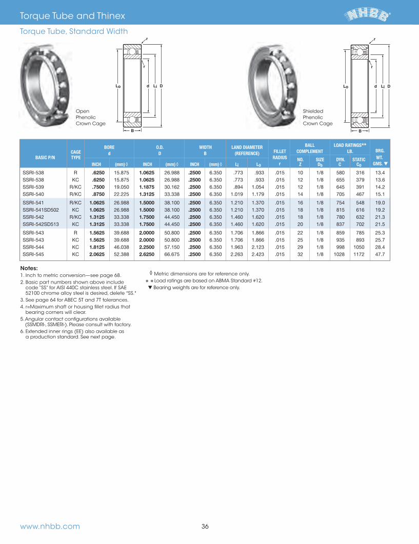
Notes: 1. Inch to metric conversion—see page 68. 2. Basic part numbers shown above include
code “SS” for AISI 440C stainless steel. If SAE 52100 chrome alloy steel is desired, delete "SS."
3. See page 64 for ABEC 5T and 7T tolerances. 4. r=Maximum shaft or housing fillet radius that
bearing corners will clear. 5. Angular contact configurations available
(SSMDRI-, SSMERI-). Please consult with factory. 6. Extended inner rings (EE) also available as
a production standard. See next page.
◊ Metric dimensions are for reference only.
**Load ratings are based on ABMA Standard #12. ▼ Bearing weights are for reference only.
Shielded Phenolic Crown Cage
r
r
Lid D
B
Lo
r
r
Lid D
B
Lo
OpenPhenolic Crown Cage
.6250 1.0625 .2500
.6250 1.0625 .2500
.7500 1.1875 30.162 .2500
.8750 22.225 1.3125 .2500
1.0625 1.5000 .2500 1.0625 1.5000 .2500 1.3125 1.7500 .2500 1.3125 1.7500 .2500
1.5625 2.0000 .2500 1.5625 2.0000 .2500 1.8125 2.2500 .2500 2.0625 2.6250 .2500
BORE O.D. WIDTH LAND DIAMETER BALL LOAD RATINGS** CAGE d D B (REFERENCE) FILLET COMPLEMENT LB. BRG. BASIC P/N TYPE RADIUS NO. SIZE DYN. STATIC WT. INCH (mm)◊ INCH (mm)◊ INCH (mm)◊ Li Lo r Z Db C Co GMS. ▼
Torque Tube and Thinex
Torque Tube, Standard Width
66844_Text.indd 38 11/16/12 9:45 AM

www.nhbb.com 37
r
r
Lid D
B
Lo
r
r
Lid D
B
Lo
Notes: 1. Inch to metric conversion—see page 68. 2. Basic part numbers shown above include
code “SS” for AISI 440C stainless steel. If SAE 52100 chrome alloy steel is desired, delete "SS."
3. See page 64 for ABEC 5T and 7T tolerances. 4. r=Maximum shaft or housing fillet radius that
bearing corners will clear. 5. Angular contact configurations available
(SSMDRI-, SSMERI-), please consult with factory.
◊ Metric dimensions are for reference only.
**Load ratings are based on ABMA Standard #12. ▼ Bearing weights are for reference only.
Shielded Phenolic Crown Cage
OpenPhenolic Crown Cage
.6250 1.0625 .2812 .2500
.6250 1.0625 .2812 .2500
.7500 1.1875 30.162 .2812 .2500
.8750 22.225 1.3125 .2812 .2500
1.0625 1.5000 .2812 .2500 1.0625 1.5000 .2812 .2500 1.3125 1.7500 .2812 .2500 1.3125 1.7500 .2812 .2500
1.5625 2.0000 .2812 .2500 1.5625 2.0000 .2812 .2500 1.8125 2.2500 .2812 .2500 2.0625 2.6250 .2812 .2500
BORE O.D. INNER WIDTH OUTER WIDTH LAND DIAMETER BALL LOAD RATINGS** CAGE d D Bi Bo (REFERENCE) FILLET COMPLEMENT LB. BRG. BASIC P/N TYPE RADIUS NO. SIZE DYN. STATIC WT. INCH (mm)◊ INCH (mm)◊ INCH (mm)◊ INCH (mm)◊ Li Lo r Z Db C Co GMS. ▼
Torque Tube and Thinex
Torque Tube, Extended Inner Ring
66844_Text.indd 39 11/16/12 9:45 AM

www.nhbb.com 38
Notes: 1. Inch to metric conversion—see page 68. 2. Basic part numbers shown above include
code “SS” for AISI 440C stainless steel. If SAE 52100 chrome alloy steel is desired, delete "SS."
3. See page 64 for ABEC 5T and 7T tolerances. 4. r=Maximum shaft or housing fillet radius that
bearing corners will clear. 5. Angular contact configurations available
(SSMDRI-, SSMERI-). Please consult with factory. 6. Extended inner rings (EE) also available as
a production standard.
* The “R” Ribbon cage is available as indicated. Please consult with factory for machined cage availability.
◊ Metric dimensions are for reference only.
**Load ratings are based on ABMA Standard #12. ♦ Limited retainer options available.
Please consult with factory. ▼ Bearing weights are for reference only. † Single or double shielded or sealed configura-
tion with specific internal design may be avail- able in the open width.
.3750 .6250 .1562 .1562
.5000 .7500 .1562 .1562
.6250 .8750 22.225 .1562 .1562
.6250 .8750 22.225 .1562
.7500 1.0000 .1562 .1562
.7500 1.0000 .1562
.8750 22.225 1.1250 .1562 .1562
.8750 22.225 1.1250 .1562
♦† 1.0625 1.3125 .1562 .1960 ♦† 1.2500 1.5000 .1562 .1960
BORE O.D. WIDTH B LAND DIAMETER BALL LOAD RATINGS** CAGE d D OPEN SHIELDED (REFERENCE) FILLET COMPLEMENT LB. BRG. BASIC P/N TYPE RADIUS NO. SIZE DYN. STATIC WT. * INCH (mm)◊ INCH (mm)◊ INCH (mm)◊ INCH (mm)◊ Li Lo r Z Db C Co GMS.▼
Shielded Phenolic Crown Cage
r
r
Lid D
B
Lo
r
r
Lid D
B
Lo
OpenPhenolic Crown Cage
Torque Tube and Thinex
Thinex
66844_Text.indd 40 11/16/12 9:45 AM

www.nhbb.com
40 Middle Size Metric Series – Radial, Unflanged
41 Miniature Metric L Series – Radial, Open, Unflanged and Flanged
42 Miniature Metric L Series – Radial, Shielded, Unflanged and Flanged
43 Miniature Metric R Series – Radial, Open, Unflanged and Flanged
44 Miniature Metric R Series – Radial, Shielded, Unflanged and Flanged
Metric Series
Contents
39
66844_Text.indd 41 11/16/12 9:45 AM

www.nhbb.com
✩ 10.0 22.0 6.0 .30 ✩ 10.0 26.0 1.0236 8.0 .30 10.0 26.0 1.0236 8.0 .30 ✩ 10.0 30.0 9.0 .61 ✩ 10.0 30.0 9.0 .61
✩ 12.0 24.0 6.0 .30 12.0 24.0 6.0 .30 ✩ 12.0 28.0 8.0 .30
12.0 32.0 10.0 .61 ✩ 15.0 24.0 5.0 .30
✩ 15.0 28.0 7.0 .30 ✩ 15.0 32.0 9.0 .30 ✩ 15.0 35.0 11.0 .61
17.0 30.0 7.0 .30 ✩ 17.0 35.0 10.0 .30
17.0 40.0 12.0 .61 20.0 37.0 9.0 .30 20.0 42.0 1.6535 12.0 .61 20.0 47.0 14.0 1.02
✩ 25.0 37.0 7.0 .30
25.0 42.0 1.6535 9.0 .30 25.0 47.0 12.0 .61
LAND DIAMETER FILLET BALL LOAD RATINGS ** BORE O.D. WIDTH (REFERENCE) RADIUS COMPLEMENT LB. BASIC P/N CAGE TYPE d D B
Li Lo
r NO. SIZE DYN. STATIC * mm (INCH)◊ mm (INCH)◊ mm (INCH)◊ mm mm mm (INCH) Z Db C Co
r
r
Lo d DLi
BShielded Ribbon Cage
Open Ribbon Cage
Notes:1. Metric to inch conversion—see page 68.2. Basic part numbers shown above include code
“SS” for AISI 440C stainless steel. If SAE 52100 chrome alloy steel is desired, delete "SS."
3. Tolerances per ABMA standard #20.4. r=Maximum shaft or housing fillet radius that
bearing corners will clear.
5. While we have the capability to produce the sizes listed, they are not all currently in produc-tion. Please consult with factory for minimum order quantity and quote.
6. Add “Z” for single shield, “ZZ” for two shields, as a suffix to basic part number.
* Please consult with factory for machined cage options. ◊ Inch conversions are given for reference only.
**Load ratings are based on ABMA Standard #9.
✩ Production standard.
Middle Size Metric Series
Radial, Unflanged
40
r
r
Lo d DLi
B
66844_Text.indd 42 11/16/12 9:45 AM

www.nhbb.com
1.0 3.0 1.0 .051.0 3.0 1.5 .05
✩ 1.5 4.0 1.2 .05 ✩ ▲ H 1.5 4.0 1.2 .05 ✩ 2.0 5.0 1.5 .08
2.5 6.0 .2362 1.8 .08 ✩ 3.0 6.0 .2362 2.0 .08 ✩ 3.0 7.0 2.0 .10 ✩ 4.0 7.0 2.0 .08
4.0 8.0 .3150 2.0 .10
✩ 4.0 9.0 2.5 .104.0 10.0 3.0 .155.0 8.0 .3150 2.0 .08 5.0 9.0 2.5 .105.0 10.0 3.0 .15
✩ 5.0 11.0 3.0 .15 ✩ 6.0 .2362 10.0 2.5 .10
6.0 .2362 12.0 3.0 .15 ✩ 6.0 .2362 13.0 3.5 .15
7.0 11.0 2.5 .10
7.0 13.0 3.0 .15 ✩ 7.0 14.0 .5512 3.5 .15
8.0 .3150 12.0 2.5 .108.0 .3150 14.0 .5512 3.5 .15
✩ 8.0 .3150 16.0 4.0 .20
9.0 17.0 4.0 .209.0 20.0 5.0 - .30
✩ 10.0 19.0 5.0 - .30 ✩ 10.0 19.0 5.0 - — 12.22 16.50 .30
r
r
Lo d DLi
B
r
BfB
DfLoD Li d
r
UnflangedRibbon Cage
Flanged Ribbon Cage
BORE O.D. WIDTH FLANGE FLANGE LAND DIAMETER
FILLET BALL LOAD RATINGS** CAGE d D B DIA. WIDTH (REFERENCE) RADIUS COMPLEMENT LB. BASIC P/N † TYPE Df Bf Li
Lo r NO. SIZE Dyn. STATIC
* mm (INCH)◊ mm (INCH)◊ mm (INCH)◊ mm mm mm mm mm (INCH)◊ Z Db C Co
Notes: 1. Metric to inch conversion—see page 68. 2. Basic part numbers shown above include code
“SS” for AISI 440C stainless steel. If SAE 52100 chrome alloy steel is desired, delete "SS."
3. See page 63 for ABEC tolerances. 4. r=Maximum shaft or housing fillet radius that
bearing corners will clear.
5. While we have the capability to produce the sizes listed, they are not all currently in produc-tion. Please consult with factory for minimum order quantity and quote.
† For flanged bearing, substitute prefix "SSLF-" when applicable.
* Please consult with factory for cage availability. ▲ Available only as flanged type. ◊ Inch conversions are given for reference only.
** Load ratings are based on ABMA Standard #12.
✩ Production standard.
41
Miniature Metric L Series
Radial, Open, Unflanged and Flanged
66844_Text.indd 43 11/16/12 9:45 AM

www.nhbb.com
BORE O.D. WIDTH FLANGE FLANGE LAND DIAMETER
FILLET BALL LOAD RATINGS** CAGE d D B DIA. WIDTH (REFERENCE) RADIUS COMPLEMENT LB. BASIC P/N † TYPE Df Bf Li
Lo r NO. SIZE Dyn. STATIC
* mm (INCH)◊ mm (INCH)◊ mm (INCH)◊ mm mm mm mm mm (INCH)◊ Z Db C Co
2.0 5.0 2.3 .082.5 6.0 .2362 2.6 .083.0 6.0 .2362 2.5 .08
✩ 3.0 7.0 3.0 .10 ✩ 3.0 7.0 3.0 .10
4.0 7.0 2.5 .084.0 8.0 .3150 3.0 .104.0 9.0 4.0 .10
✩ ▲ 4.0 9.0 4.0 .104.0 10.0 4.0 .15
5.0 8.0 .3150 2.5 .085.0 9.0 3.0 .105.0 10.0 4.0 .15
✩ 5.0 11.0 5.0 .15 ✩ 6.0 .2362 10.0 3.0 .10
✩ 6.0 .2362 10.0 3.0 .106.0 .2362 12.0 4.0 .156.0 .2362 13.0 5.0 .15 7.0 11.0 3.0 .10
✩ 7.0 13.0 4.0 .15
✩ 7.0 14.0 .5512 5.0 .158.0 .3150 12.0 3.5 .108.0 .3150 14.0 .5512 4.0 .15
✩ 8.0 .3150 16.0 5.0 .20 ✩ 8.0 .3150 16.0 6.0 .20
9.0 17.0 5.0 .209.0 20.0 6.0 .30
✩ 10.0 19.0 7.0 .30 ✩ 10.0 19.0 5.0 .30
r
Df
r
D d LoLi
BfB
FlangedShielded Ribbon Cage
UnflangedShielded Ribbon Cage
Notes:1. Metric to inch conversion—see page 68.2. Basic part numbers shown above include code
“SS” for AISI 440C stainless steel. If SAE 52100 chrome alloy steel is desired, delete "SS."
3. See page 63 for ABEC tolerances.4. r=Maximum shaft or housing fillet radius that
bearing corners will clear.
5. While we have the capability to produce the sizes listed, they are not all currently in production. Please consult with factory for minimum order quantity and quote.
6. Add “Z” for single shield, “ZZ” for two shields, as a suffix to basic part number before “Y” or “W” width variations.
† For flanged bearing, substitute prefix "SSLF-" when applicable.
* Please consult with factory for cage availability. ▲ Available only as flanged type. ◊ Inch conversions are given for reference only.
** Load ratings are based on ABMA Standard #12.
✩ Production standard.
42
Miniature Metric L Series
Radial, Shielded, Unflanged and Flanged
r
r
Lo d DLi
B
66844_Text.indd 44 11/16/12 9:45 AM

www.nhbb.com
BORE O.D. WIDTH FLANGE FLANGE LAND DIAMETER
FILLET BALL LOAD RATINGS** CAGE d D B DIA. WIDTH (REFERENCE) RADIUS COMPLEMENT LB. BASIC P/N † TYPE Df Bf Li
Lo r NO. SIZE Dyn. STATIC
* mm (INCH)◊ mm (INCH)◊ mm (INCH)◊ mm mm mm mm mm (INCH)◊ Z Db C Co
1.2 4.0 1.8 .10 1.5 5.0 2.0 .15 1.5 6.0 .2362 2.5 .15 2.0 6.0 .2362 2.3 .15 2.0 7.0 2.8 .15
2.5 7.0 2.5 .15 2.5 8.0 .3150 2.8 .15 3.0 8.0 .3150 3.0 .15 3.0 9.0 3.0 .15
✩ 3.0 10.0 4.0 .15
✩ 4.0 11.0 4.0 .15 4.0 12.0 4.0 .20 4.0 13.0 5.0 .20
✩ 4.0 16.0 5.0 .30 ✩ 5.0 13.0 4.0 .20
5.0 14.0 .5512 5.0 .20 ✩ 5.0 16.0 5.0 .30 ✩ 5.0 19.0 6.0 .30
6.0 .2362 15.0 5.0 .15 6.0 .2362 17.0 6.0 .20
✩ 6.0 .2362 19.0 6.0 .30 ✩ 7.0 19.0 6.0 .30 ✩ 7.0 22.0 7.0 .30 ✩ 8.0 .3150 22.0 7.0 .30 ✩ 9.0 26.0 1.0236 8.0 .30
r
BfB
DfLoD Li d
r
r
r
Lo d DLi
BFlanged Ribbon Cage
Unflanged Ribbon Cage
Notes:1. Metric to inch conversion—see page 68.2. Basic part numbers shown above include code
“SS” for AISI 440C stainless steel. If SAE 52100 chrome alloy steel is desired, delete "SS."
3. See page 63 for ABEC tolerances.4. r=Maximum shaft or housing fillet radius that
bearing corners will clear.
5. While we have the capability to produce
the sizes listed, they are not all currently in production. Please consult with factory for minimum order quantity and quote.
† For flanged bearing, substitute prefix "SSRF-" when applicable.
* Please consult with factory for cage availability. ◊ Inch conversions are given for reference only.
** Load ratings are based on ABMA Standard #12.
✩ Production standard.
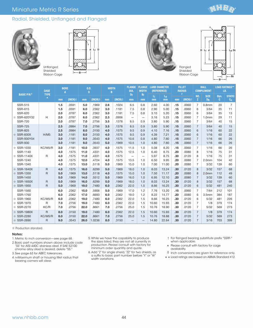
Miniature Metric R Series
Radial, Open, Unflanged and Flanged
43
66844_Text.indd 45 11/16/12 9:45 AM
www.nhbb.com
BORE O.D. WIDTH FLANGE FLANGE LAND DIAMETER
FILLET BALL LOAD RATINGS** CAGE d D B DIA. WIDTH (REFERENCE) RADIUS COMPLEMENT LB. BASIC P/N † TYPE Df Bf Li
Lo r NO. SIZE Dyn. STATIC
* mm (INCH)◊ mm (INCH)◊ mm (INCH)◊ mm mm mm mm mm (INCH)◊ Z Db C Co
1.5 5.0 2.6 .15 1.5 6.0 .2362 3.0 .15 2.0 6.0 .2362 3.0 .15
✩ 2.0 6.0 .2362 2.3 .15 2.0 7.0 3.5 .15
2.5 7.0 3.5 .15 2.5 8.0 .3150 4.0 .15
✩ 3.0 8.0 .3150 4.0 .15 3.0 9.0 4.0 .15 3.0 9.0 5.0 .15
✩ 3.0 10.0 4.0 .15 4.0 11.0 4.0 .20
✩ 4.0 11.0 4.0 .30 4.0 12.0 4.0 .20 4.0 13.0 5.0 .20
✩ 4.0 16.0 5.0 .30 ✩ 5.0 13.0 4.0 .20
5.0 14.0 .5512 5.0 .20 ✩ 5.0 16.0 5.0 .30 ✩ 5.0 19.0 6.0 .30
6.0 .2362 15.0 5.0 .15 6.0 .2362 17.0 6.0 .20
✩ 6.0 .2362 19.0 6.0 .30 ✩ 7.0 19.0 6.0 .30 ✩ 7.0 22.0 7.0 .30
✩ 8.0 .3150 19.0 6.0 .30 ✩ 8.0 .3150 22.0 7.0 .30 ✩ 9.0 26.0 1.0236 8.0 .30
r
Df
r
D d LoLi
BfB
FlangedShielded Ribbon Cage
UnflangedShielded Ribbon Cage
Notes:1. Metric to inch conversion—see page 68.2. Basic part numbers shown above include code
“SS” for AISI 440C stainless steel. If SAE 52100 chrome alloy steel is desired, delete "SS."
3. See page 63 for ABEC tolerances.4. r=Maximum shaft or housing fillet radius that
bearing corners will clear.
5. While we have the capability to produce the sizes listed, they are not all currently in production. Please consult with factory for minimum order quantity and quote.
6. Add “Z” for single shield, “ZZ” for two shields, as a suffix to basic part number before “Y” or “W” width variations.
† For flanged bearing substitute prefix "SSRF-" when applicable.
* Please consult with factory for cage availability. ◊ Inch conversions are given for reference only.
** Load ratings are based on ABMA Standard #12.
✩ Production standard.
Miniature Metric R Series
Radial, Shielded, Unflanged and Flanged
44
r
r
Lo d DLi
B
66844_Text.indd 46 11/16/12 9:45 AM
www.nhbb.com 45
Engineering
Contents
46 Engineering Services
47 Materials
49 Cages
52 Seals and Shields
53 Internal Bearing Geometry
55 Lubrication
57 Preload and Duplex Ball Bearings
58 Load Ratings and Bearing Life
61 Mounting and Coding
62 Recommended Fits
63 Tolerances
65 Torque
65 Post Service Analysis
66 Interchange Chart
68 Metric Conversion Table
69 Temperature Conversion Table
The information contained in this section is provided to assist you
with selecting the proper ball bearing product for your application.
Early involvement of NHBB applications engineering is recommended
to assure that the product chosen meets your critical requirements
for performance, life, and cost.
66844_Text.indd 47 11/16/12 9:45 AM

Computer Design and AnalysisNHBB utilizes computerized design capabilities to examine and
analyze complex ball bearing applications. These capabilities
ensure that the ultraprecision ball bearing you select will meet
your specific requirements for performance, life, and cost.
Engineering Test LaboratoryWe maintain a fully equipped engineering test laboratory that
enables us to validate the performance characteristics of our ball
bearing designs. The lab contains a full complement of commer-
cially available equipment, as well as specialized equipment
developed by NHBB and precisely tailored for specific test
requirements, such as our patented high speed bearing vibra-
tional analysis system.
Materials LaboratoryOur materials laboratory is specifically designed and equipped
to perform complex chemical, metallurgical, and visual analysis
of the many component parts in ball bearings. The lab is also
used to perform wear and failure studies on customer bearings.
Metallurgical studies are conducted with a metallograph and
micro-hardness testers. The metallograph performs micro-struc-
ture photography at magnifications from 25 to 2,000 times.
Micro-hardness testers use diamond indentors under loads from
1 to 10,000 grams to test material hardness. More in depth stud-
ies of surface topography and material composition are possible
During laboratory wear studies, ball bearings are disassembled
be permanently recorded with a 200X photo-microscope for
analysis and future reference.
Functional Tests for Ball BearingsNHBB has devised a series of rigidly monitored tests that measure
starting and running torque, as well as vibration or “noise” levels.
During testing, a ball bearing is normally mounted with a thrust
load applied.
movements.
rotation under a certain load after rotation has been initiated.
NHBB measures running torque values at standard speeds of
test is fully monitored with results permanently recorded onto a
strip chart. This chart may be analyzed for various ball bearing
characteristics, such as surface finish, contamination, brinelling,
and overall geometry. The test for running torque is time
consuming and primarily used on a sample basis or for perform-
ing diagnostic analysis. Both starting and running torque tests
the consistent performance of every bearing we manufacture.
and vibration under a controlled load and speed.
Please consult NHBB Engineering for recommendations on the
many specialized tests we can perform.
46www.nhbb.com
Engineering
Engineering Services
Anderonmeter, Dynamic Noise and Vibration Tester
66844_Text.indd 48 11/16/12 9:45 AM
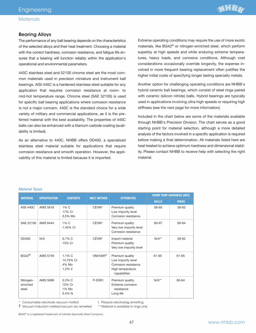
47
Bearing AlloysThe performance of any ball bearing depends on the characteristics
of the selected alloys and their heat treatment. Choosing a material
with the correct hardness, corrosion resistance, and fatigue life en-
sures that a bearing will function reliably within the application's
operational and environmental parameters.
-
mon materials used in precision miniature and instrument ball
application that requires corrosion resistance at room- to
for specific ball bearing applications where corrosion resistance
variety of military and commercial applications, as it is the pre-
-
stainless steel material suitable for applications that require
corrosion resistance and smooth operation. However, the appli-
cability of this material is limited because it is imported.
Extreme operating conditions may require the use of more exotic ® or nitrogen-enriched steel, which perform
superbly at high speeds and while enduring extreme tempera-
considerations occasionally override longevity, the expense in-
volved in more frequent bearing replacement often justifies the
higher initial costs of specifying longer lasting specialty metals.
hybrid ceramic ball bearings, which consist of steel rings paired
used in applications involving ultra-high speeds or requiring high
through NHBB's Precision Division. The chart serves as a good
starting point for material selection, although a more detailed
analysis of the factors involved in a specific application is required
heat treated to achieve optimum hardness and dimensional stabil-
ity. Please contact NHBB to receive help with selecting the right
material.
www.nhbb.com
Engineering
Materials
ROOM TEMP. HARDNESS (HRC) MATERIAL SPECIFICATION CONTENTS MELT METHOD ATTRIBUTES
BALLS RINGS
0.5% Mo Corrosion resistance
Corrosion resistance
13% Cr Premium quality Very low impurity level
® ◊ Premium quality 61-65 61-65
1.2% V High temperature capabilities
† enriched 15% Cr Extreme corrosion steel 1% Mo resistance
* Consumable electrode vacuum melted ◊ Vacuum induction melted/vacuum arc remelted
† Pressure electroslag remelting ** Material is available in rings only.
Material Types
BG42® is a registered trademark of Latrobe Specialty Steel Company.
66844_Text.indd 49 11/16/12 9:45 AM

48www.nhbb.com
Engineering
Materials
Alternative Ball MaterialCERBEC® silicon nitride balls
® silicon nitride
and inertness of silicon nitride offer significant bearing perfor-
mance advantages, including higher operating speeds, extended
bearing life, and expanded design possibilities for unique and
demanding bearing applications.
Typical Applications
ROOM TEMP. MATERIAL SPECIFICATION ATTRIBUTES HARDNESS (HRC)
® Nitride silicon lighter weight, higher stiffness nitride
Performance Benefits
Hybrid Ceramic Bearings
CERBEC® is a registered trademark of Saint-Gobain Performance Plastics Corporation.
Specifications
PROPERTIES
IMPROVEMENT IN BEARING PERFORMANCE
than steel Decreased centrifugal force Decreased gyroscopic movement
Corrosion resistance Durability in harsh environments
Higher maximum temperature: Wider operating range 1000˚C vs. 320˚C for steel
Radial Hybrid Ceramic Bearing with Phenolic Crown Retailer
66844_Text.indd 50 11/16/12 9:45 AM
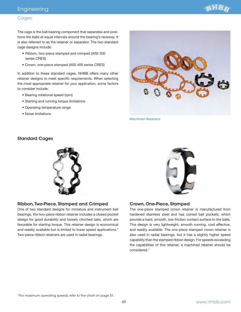
49 www.nhbb.com
Engineering
Cages
Ribbon, Two-Piece, Stamped and CrimpedOne of two standard designs for miniature and instrument ball bearings, the two-piece ribbon retainer includes a closed pocket design for good durability and loosely clinched tabs, which are favorable for starting torque. This retainer design is economical
Two-piece ribbon retainers are used in radial bearings.
Crown, One-Piece, StampedThe one-piece stamped crown retainer is manufactured from hardened stainless steel and has coined ball pockets, which provide a hard, smooth, low-friction contact surface to the balls. This design is very lightweight, smooth running, cost effective, and readily available. The one-piece stamped crown retainer is also used in radial bearings, but it has a slightly higher speed capability than the stamped ribbon design. For speeds exceeding the capabilities of this retainer, a machined retainer should be
The cage is the ball bearing component that separates and posi-
is also referred to as the retainer or separator. The two standard cage designs include:
retainer designs to meet specific requirements. When selecting the most appropriate retainer for your application, some factors to consider include:
Standard Cages
Machined Retainers
*For maximum operating speeds, refer to the chart on page 51.
66844_Text.indd 51 11/16/12 9:45 AM

50www.nhbb.com
Engineering
Cages
Meldin® is a registered trademark of Saint-Gobain Performance Plastics Corporation.
Delrin® is a registered trademark of DuPont.
Full Type, One-PieceThis retainer design is best suited for ultra-high speed applica-
high speeds. This retainer, which can only be utilized with angular contact bearings, is manufactured from a variety of materials to meet specific application requirements, including paper and linen-based phenolics and polyamide-imide. Both phenolic materials may be vacuum impregnated with oil, allowing for bet-ter lubricity within the ball pockets. The polyamide-imide mate-rial is fully autoclavable, making it well suited for many medical
small amount of graphite and PTFE, which aids in lubricity
silver coating.
Crown, One-PieceFor high speed applications, a machined crown retainer design is a more appropriate choice than the two standard designs
meet specific application requirements, including paper and linen-based phenolics and polyamide-imide. Both phenolic mate-rials can be vacuum impregnated with oil, allowing for better lubricity within the ball pockets. The polyamide-imide material is fully autoclavable, making it well suited for many medical and
small amount of graphite and PTFE, which aids in lubricity
silver coating.
Alternative Machined Cage MaterialsNHBB manufactures machined cages from the following materials
®
®
Molded Cages
Division offers a limited variety of molded retainers. These may
have a lower speed capability as compared to machined
retainers, which is mainly due to the fact that machined retainers
may be held to tighter tolerances for critical dimensions.
Machined Cages
Machined Phenolic Crown Cage Machined Polyamide-imide Full Type Cage
66844_Text.indd 52 11/16/12 9:45 AM
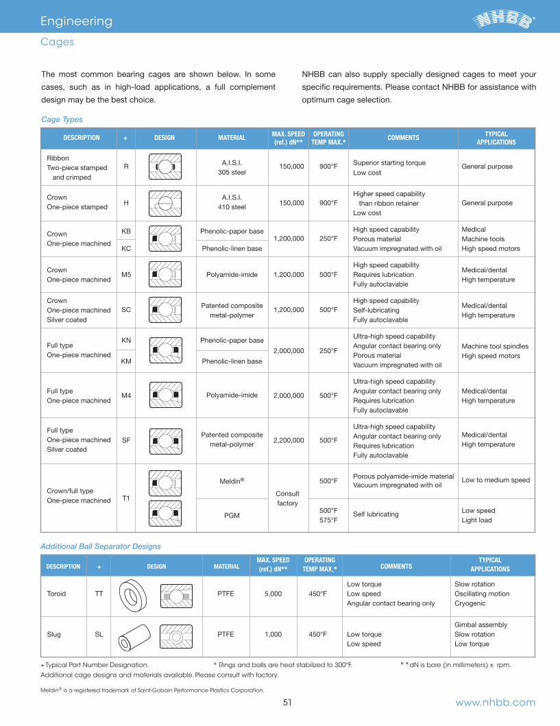
51
DESCRIPTION + DESIGN MATERIAL MAX. SPEED OPERATING COMMENTS TYPICAL (ref.) dN** TEMP MAX.* APPLICATIONS
General purpose
Two-piece stamped
305 steel
and crimped
Crown H
Higher speed capability
General purpose One-piece stamped than ribbon retainer
Crown KB Phenolic-paper base High speed capability Medical One-piece machined
Porous material Machine tools KC Phenolic-linen base Vacuum impregnated with oil High speed motors
Crown High speed capability
One-piece machined High temperature
Fully autoclavable
Crown Patented composite
High speed capability
One-piece machined metal-polymer High temperature
Full type
KN Phenolic-paper base
Machine tool spindles One-piece machined
KMHigh speed motors Porous material
Phenolic-linen base Vacuum impregnated with oil
Full type
l
One-piece machined High temperature
Polyamide-imide
Fully autoclavable
Full type Patented composite
One-piece machined
metal-polymer High temperature
Fully autoclavable
Porous polyamide-imide material
Meldin® Vacuum impregnated with oil
T1 Consult
One-piece machined
factory
PGM
cases, such as in high-load applications, a full complement
design may be the best choice.
NHBB can also supply specially designed cages to meet your
specific requirements. Please contact NHBB for assistance with
optimum cage selection.
Cage Types
+ Typical Part Number Designation. * Rings and balls are heat stabilized to 300°F. **dN is bore (in millimeters) x rpm.
Additional cage designs and materials available. Please consult with factory.
Meldin® is a registered trademark of Saint-Gobain Performance Plastics Corporation.
DESCRIPTION + DESIGN MATERIAL MAX. SPEED OPERATING
COMMENTS TYPICAL
(ref.) dN** TEMP MAX.* APPLICATIONS
Gimbal assembly
Additional Ball Separator Designs
Engineering
Cages
www.nhbb.com
66844_Text.indd 53 11/16/12 9:45 AM

www.nhbb.com 52
and assist in preventing contaminants from reaching internal
surfaces. When specifying a seal or shield, consideration should
be given to the compatibility of the cage and enclosure type to
it may be advantageous to use shields rather than seals because
there are no contacting surfaces to create drag.
The following chart includes the common types of shields and
seals offered by NHBB. Please consult the factory for help in
determining the appropriate seal or shield for your particular
application.
Seal and Shield Types
DESCRIPTION TYPE DESIGN MATERIAL MAX. OPERATING TEMP.*
Minimal clearance Most popular
Provides minimal clearance to light contact resulting in low torque
Excellent sealing characteristics Metallic backing plate
Excellent sealing characteristics
® Excellent sealing characteristics High cost
Excellent sealing characteristics
lip riding Excellent sealing characteristics
Engineering
Seals and Shields
Viton® is a registered trademark of DuPont.
* Rings and balls are heat stabilized to 300°F.
66844_Text.indd 54 11/16/12 9:45 AM

When a ball bearing is running under a load, force is transmitted
contact area between each ball and the rings is relatively small,
moderate loads can produce stresses of tens, even hundreds of
thousands, of pounds per square inch. These internal stresses
have a significant impact on the bearing’s life and performance.
The internal geometry of a bearing —its radial play, raceway
curvature and contact angle—must be carefully chosen so loads
will be distributed for optimal performance.
Radial and Axial PlayMost ball bearings are assembled so that a slight amount of
looseness exists between the balls and the raceways. This
is the maximum distance that one bearing ring may be displaced
with respect to the other in a direction perpendicular to the bear-
end play, is the maximum relative displacement between the two
rings of an unmounted ball bearing in a direction parallel to the
bearing axis.
same degree of looseness between the components, they bear a
mutual dependence, yet their values are usually quite different in
in., while axial play may range from .001 in. to .010 in. The
suggested radial play ranges for typical applications should
always be consulted when a device is in the initial design phase.
Suggested Radial Play
critical than axial play. While radial play has become the standard
purchasing specification, you may also specify axial play require-
ments. Keep in mind, however, the values of radial play and axial
play for any given bearing design are mathematically interdepen-
actual radial play remaining after assembly of the complete
device, the radial play specification for the bearing must be modified
in accordance with the discussion in the mounting and coding
section on page 61.
Free Angle of Misalignment
permitted to exist between the components of most ball bear-
ings, the inner ring may be cocked or tilted a small amount with
respect to the outer ring. This displacement is called free angle
of misalignment. The amount of misalignment allowable in a ball
bearing is determined by its radial play and track curvature
values. Misalignment has positive practical significance because
it enables a ball bearing to accommodate small dimensional vari-
ations that may exist in associated shafts and housings. The
performance of a misaligned bearing will be degraded to a
certain extent, but for slight misalignments under reasonably
general, the amount of misalignment a bearing is subject to by the
shaft and housing’s physical arrangement should never exceed
the bearing’s free angle of misalignment. Free angle of misalign-
ment is typically less than one degree.
DESCRIPTION RADIAL PLAY RANGE* NHBB CODE
Tight .0001 to .0003 P13
Normal .0002 to .0005 P25
*Measurement in inches. Nonstandard ranges may be specified.
53
Engineering
Internal Bearing Geometry
Axial Play
Radial Play
F(Neg)
F(Neg)2
*Measurement in inches.
Tape guides, belt guides, low speed aps. .0002 to .0005
Gyro gimbals, horizontal axis .0002 to .0005
Precision gear trains, low speed electric motors, .0002 to .0005 synchros and servos
Gyro spin bearings, ultra-high-speed turbines Consult factory and spindles
TYPICAL APPLICATIONSUGGESTED
RADIAL PLAY*
Standard Radial Play Ranges
Radial and Axial Play
Free Angle of Misalignment
www.nhbb.com
66844_Text.indd 55 11/16/12 9:45 AM
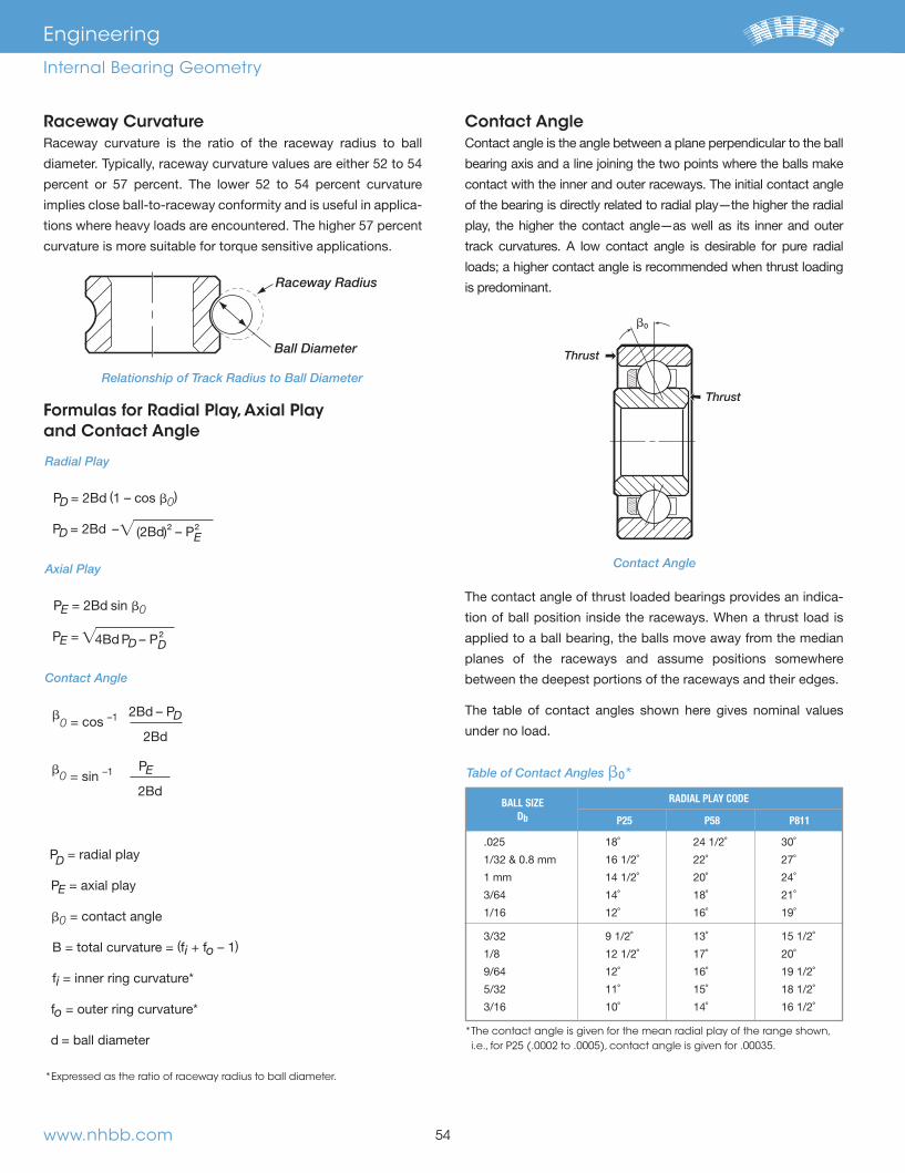
Raceway Curvature
implies close ball-to-raceway conformity and is useful in applica-
curvature is more suitable for torque sensitive applications.
Formulas for Radial Play, Axial Play and Contact Angle
Contact AngleContact angle is the angle between a plane perpendicular to the ball
bearing axis and a line joining the two points where the balls make
contact with the inner and outer raceways. The initial contact angle
of the bearing is directly related to radial play—the higher the radial
play, the higher the contact angle—as well as its inner and outer
is predominant.
Thrust
Thrust
�0
The contact angle of thrust loaded bearings provides an indica-
tion of ball position inside the raceways. When a thrust load is
applied to a ball bearing, the balls move away from the median
planes of the raceways and assume positions somewhere
between the deepest portions of the raceways and their edges.
The table of contact angles shown here gives nominal values
under no load.
Radial Play
PD = 2Bd 1 – cos b0
PD = 2Bd –
² – P²E
Axial Play
PE = 2Bd sin b0
PE = D – P²
D Contact Angle
b0 = cos –1 2B d – PD
2Bd
b0 = sin –1 PE
2Bd
PD = radial play
PE = axial play
b0 = contact angle
B = total curvature = fi o – 1
fi
fo
d = ball diameter
*Expressed as the ratio of raceway radius to ball diameter.
www.nhbb.com 54
Raceway Radius
Ball Diameter
Engineering
Internal Bearing Geometry
Contact Angle
Relationship of Track Radius to Ball Diameter
BALL SIZE RADIAL PLAY CODE Db
P25 P58 P811
Table of Contact Angles �0*
* The contact angle is given for the mean radial play of the range shown, i.e., for P25 (.0002 to .0005), contact angle is given for .00035.
�
�
66844_Text.indd 56 11/16/12 9:45 AM
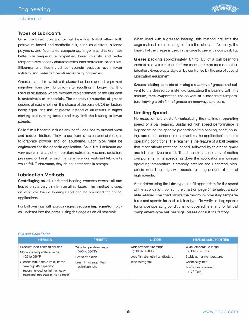
55
Types of LubricantsOil is the basic lubricant for ball bearings. NHBB offers both
petroleum-based and synthetic oils, such as diesters, silicone
better low temperature properties, lower volatility, and better
Grease is an oil to which a thickener has been added to prevent
used in situations where frequent replenishment of the lubricant
is undesirable or impossible. The operative properties of grease
depend almost wholly on the choice of the base oil. Other factors
being equal, the use of grease instead of oil results in higher
starting and running torque and may limit the bearing to lower
speeds.
and reduce friction. They range from simple sacrificial cages
to graphite powder and ion sputtering. Each type must be
very useful in areas of temperature extremes, vacuum, radiation,
pressure, or harsh environments where conventional lubricants
would fail. Furthermore, they do not deteriorate in storage.
Lubrication MethodsCentrifuging an oil-lubricated bearing removes excess oil and
leaves only a very thin film on all surfaces. This method is used
on very low torque bearings and can be specified for critical
applications.
For ball bearings with porous cages, vacuum impregnation forc-
es lubricant into the pores, using the cage as an oil reservoir.
When used with a greased bearing, this method prevents the
cage material from leaching oil from the lubricant. Normally, the
base oil of the grease is used in the cage to prevent incompatibility.
Grease packing
internal free volume is one of the most common methods of lu-
brication. Grease quantity can be controlled by the use of special
lubrication equipment.
Grease plating consists of mixing a quantity of grease and sol-
vent to the desired consistency, lubricating the bearing with this
mixture, then evaporating the solvent at a moderate tempera-
ture, leaving a thin film of grease on raceways and balls.
Limiting SpeedNo exact formula exists for calculating the maximum operating
dependent on the specific properties of the bearing, shaft, hous-
ing, and other components, as well as the application’s specific
operating conditions. The retainer is the feature of a ball bearing
that most affects rotational speed, followed by tolerance grade
and lubricant type and fill. The dimensional accuracy of mating
components limits speeds, as does the application’s maximum
precision ball bearings will operate for long periods of time at
high speeds.
of the application, consult the chart on page 51 to select a suit-
able retainer. The chart shows the maximum operating tempera-
tures and speeds for each retainer type. To verify limiting speeds
for unique operating conditions not covered here, and for full ball
complement-type ball bearings, please consult the factory.
Engineering
Lubrication
Oils and Base Fluids
PETROLEUM
Excellent load carrying abilities
Moderate temperature range
Greases with petroleum oil bases have high dN capability
SYNTHETIC
Wide temperature range
petroleum oils
SILICONE
Wide temperature range
Tend to migrate
PERFLUORINATED POLYETHER
Wide temperature range
Chemically inert
www.nhbb.com
66844_Text.indd 57 11/16/12 9:45 AM

www.nhbb.com 56
Engineering
Lubrication
TYPE dN TEMPERATURE RANGE °F (°C)
Recommended Speed Limits (dN) for Grease with Select Base Oils
Lubricant SpecificationsNHBB has included a table of commercial and military lubricants
and their recommended uses. When ball bearings are ordered
without a specified lubricant, it is the policy of NHBB to lubricate
consult the factory to select an appropriate type.
The standard quantity of oil varies with bearing size: it is
grease is 25-35% of the bearing’s internal free volume. For non-
standard applications, please consult the factory for specific
lube fill recommendations.
CODE BRAND NAME BASIC TYPE OPERATING TEMP. USES
Fuchs Mineral Oil
®
® Dupont Good lubricity properties
Carnation
EXXON Mobil
®
®
EXXON Mobil grease Good low temperature torque
®
Dupont lubricity properties
Kyodo
® Micronic®
Castrol®
Kluber
Lubrication Types
Speed FactorThe maximum usable operating speed of a grease lubricant is
dependent on the type of base oil. The speed factor is a function
Royco® is a registered trademark of Anderol Company.
Krytox® is a registered trademark of DuPont.
Bracote®, Micronic®, and Castrol® are registered trade-marks of Castrol Limited.
Rheotemp® is a registered trademark of Nye Lubricants.
66844_Text.indd 58 11/16/12 9:45 AM

Preload is defined as the initial axial load placed on a bearing or
set of bearings during installation. Preloading facilitates precise
control over the operating geometry of the bearing’s mating
parts, a useful function in applications where axial and radial
movement must be held within critical limits.
Ball bearings are preloaded in order to:
Preloading is accomplished either by using a spring preload or,
as in duplex ball bearings, through a solid stack of parts.
Spring Preloading
applies a force against the inner or outer ring of one of the bear-
ings in the assembly. The spring force is normally applied against
over a wide range of compressed length, the use of a spring for
preloading eliminates the need for holding tight location toler-
ances on machined parts. For example, retaining rings can be
used in the spindle assembly, thus saving the cost of a locating
shoulder, shims or threaded members. Normally, a spring would
not be used where the assembly must withstand reversing
thrust loads.
Duplex Ball BearingsDuplex ball bearings are stacked pairs with built-in preloads.
Duplex bearings are manufactured with the raceways of the inner
and outer rings offset slightly. When the set of bearings is
assembled, the thrust load required to press the adjacent faces
of the rings together becomes the desired preload. Duplex ball
bearings are used when precise location control is required. They
also help satisfy the requirements of increased axial and radial
The three methods of mounting preloaded duplex bearings are
PreloadOffset
loadinner
loadinner
Bearings in True State Bearings Preloaded O.D. Marking
57
Engineering
Preload and Duplex Ball Bearings
rings abut and the inner rings are drawn together, providing
maximum moment stiffness.
are capable of sharing a thrust load, providing increased thrust
capacity.
NHBB can provide assistance in selecting the appropriate
preload specifications for your application.
PreloadOffset
Bearings in True State Bearings Preloaded O.D. Marking
loadouter
loadouter
abut and the outer rings are drawn together, providing a higher
radial and axial stiffness and accommodation of misalignment.
www.nhbb.com
PreloadOffset (TYP)
Bearings in True State Bearings Preloaded O.D. Marking
loadouter
loadinner
66844_Text.indd 59 11/16/12 9:45 AM
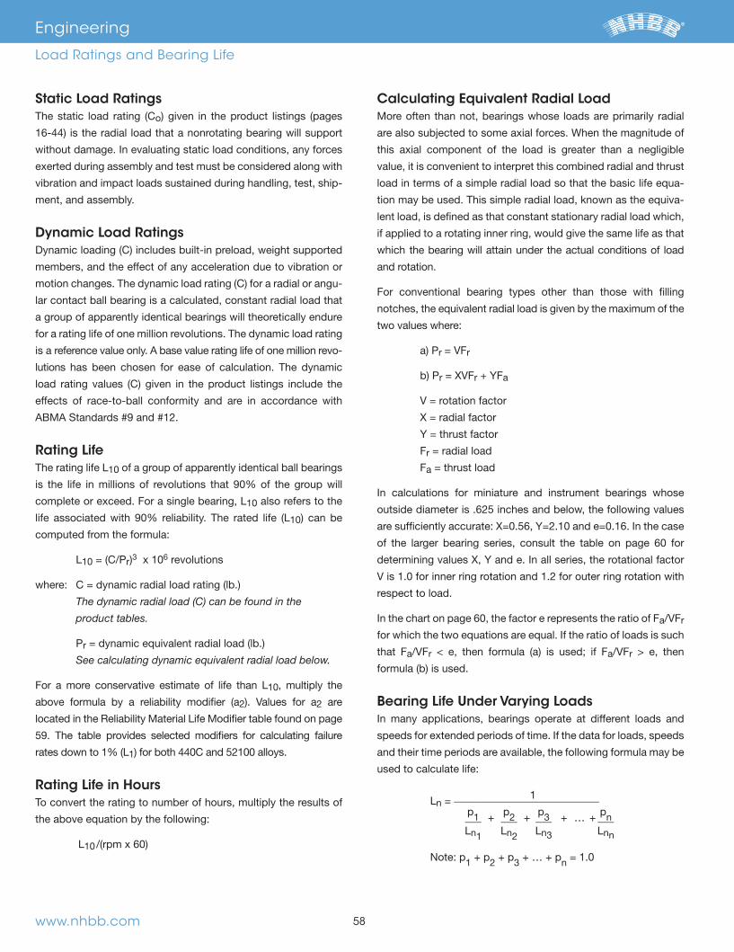
Static Load Ratingso
exerted during assembly and test must be considered along with
vibration and impact loads sustained during handling, test, ship-
ment, and assembly.
Dynamic Load Ratings
members, and the effect of any acceleration due to vibration or
-
lar contact ball bearing is a calculated, constant radial load that
a group of apparently identical bearings will theoretically endure
for a rating life of one million revolutions. The dynamic load rating
-
lutions has been chosen for ease of calculation. The dynamic
effects of race-to-ball conformity and are in accordance with
Rating Life10 of a group of apparently identical ball bearings
10 also refers to the
10
computed from the formula:
10 r 3 x 10⁶ revolutions
where:
The dynamic radial load (C) can be found in the
product tables.
Pr
See calculating dynamic equivalent radial load below.
10, multiply the
2 2 are
1
Rating Life in HoursTo convert the rating to number of hours, multiply the results of
the above equation by the following:
10
Calculating Equivalent Radial LoadMore often than not, bearings whose loads are primarily radial
are also subjected to some axial forces. When the magnitude of
this axial component of the load is greater than a negligible
value, it is convenient to interpret this combined radial and thrust
load in terms of a simple radial load so that the basic life equa-
tion may be used. This simple radial load, known as the equiva-
lent load, is defined as that constant stationary radial load which,
if applied to a rotating inner ring, would give the same life as that
which the bearing will attain under the actual conditions of load
and rotation.
For conventional bearing types other than those with filling
notches, the equivalent radial load is given by the maximum of the
two values where:
r = VFr
r = XVFr a
V = rotation factor
X = radial factor
Fr = radial load
Fa = thrust load
outside diameter is .625 inches and below, the following values
of the larger bearing series, consult the table on page 60 for
V is 1.0 for inner ring rotation and 1.2 for outer ring rotation with
respect to load.
a r
that Fa r a r > e, then
Bearing Life Under Varying Loads
and their time periods are available, the following formula may be
used to calculate life:
www.nhbb.com 58
Engineering
Load Ratings and Bearing Life
n = 1 ___________________________ p1 p2 p3 pn
n1 n2 n3 nn
Note: p1 2 3 n = 1.0
66844_Text.indd 60 11/16/12 9:45 AM

Life Modifiers10 life obtained from the basic rating life
formula described earlier will provide a satisfactory criteria for
bearing performance. For particular applications, however, it may
be desirable to consider life calculations for different reliabilities
and special bearing properties and operating conditions.
Bearing MaterialNHBB recommends reducing the load rating published for 52100
the bearing capacity is not exceeded under the most adverse
2
shown:
Elastohydrodynamics (EHD Effect)The presence of a thin film of oil at the mutually contacting
ball-to-raceway interface enhances the load capacity of a
ball bearing.
Lubricant Life
This is usually the case for applications involving very light loads
fatigue life calculated will be unrealistically high. The lubricant’s
ability to provide sufficient film strength is affected by:
-
mance characteristics over an extended period, are available.
Other Life Adjustments
life has to be modified due to application abnormalities, inten-
tional or unknown. The following conditions have the practical
10
While it is difficult to provide the exact effect upon life under any
of these conditions, NHBB is able to provide bearing life
estimates based on empirical data to help you forecast bearing
life for your application.
59
Engineering
Load Ratings and Bearing Life
Table of Reliability Material Life Modifier (a2)
www.nhbb.com
REQUIRED LN
52100 440C RELIABILITY (%) a2 = a2 =
10 1.00 0.50
5 0.62 0.31
3
2
1 0.21 0.11
66844_Text.indd 61 11/16/12 9:45 AM

www.nhbb.com 60
Engineering
Load Ratings and Bearing Life
IN RELATION TO THE LOAD SINGLE ROW BEARINGS BEARING THE INNER RING IS: TYPE UNITS ROTATING STATIONARY LB., IN. V V X Y e
1,000 1.00 0.52
100 1.52 0.36
10
300 1.12 0.50 500 1.02 0.55
1,000 1.00 0.56
Table A: Factors X, V and Y
FaZD2 Fa > e
VFr
Nomenclature is as follows:- V = rotation factor- X = radial factor- Y = thrust factor- Fr = radial load- Fa = thrust load- Z = number of balls- D = ball diameter in inches
Values of X, Y, and e for load or contact angle other than shown are obtained by linear interpolation.
Turn to page 58 for instructions on how to calculate equivalent radial load.
66844_Text.indd 62 11/16/12 9:45 AM
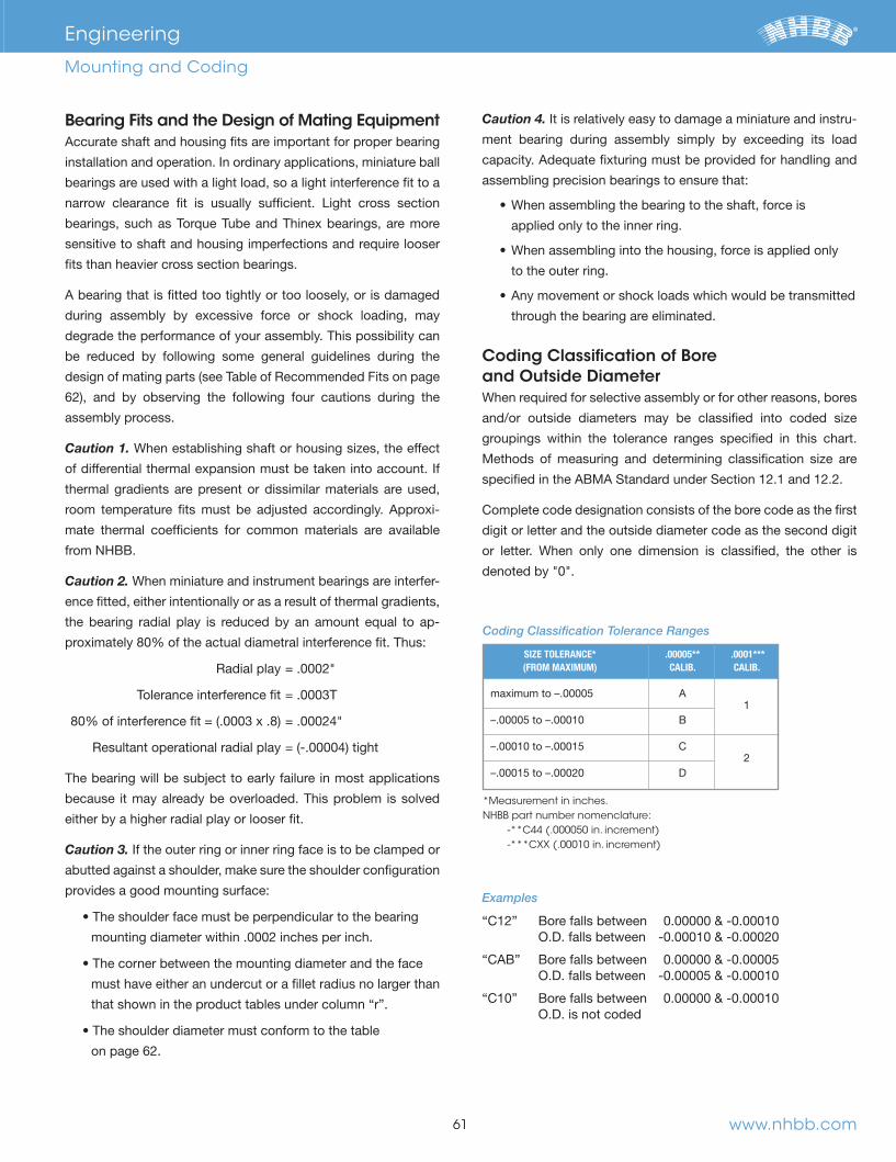
Bearing Fits and the Design of Mating Equipment
bearings are used with a light load, so a light interference fit to a
bearings, such as Torque Tube and Thinex bearings, are more
sensitive to shaft and housing imperfections and require looser
fits than heavier cross section bearings.
during assembly by excessive force or shock loading, may
degrade the performance of your assembly. This possibility can
be reduced by following some general guidelines during the
assembly process.
Caution 1. When establishing shaft or housing sizes, the effect
thermal gradients are present or dissimilar materials are used,
-
mate thermal coefficients for common materials are available
from NHBB.
Caution 2. When miniature and instrument bearings are interfer-
ence fitted, either intentionally or as a result of thermal gradients,
the bearing radial play is reduced by an amount equal to ap-
Tolerance interference fit = .0003T
The bearing will be subject to early failure in most applications
because it may already be overloaded. This problem is solved
either by a higher radial play or looser fit.
Caution 3.
abutted against a shoulder, make sure the shoulder configuration
provides a good mounting surface:
mounting diameter within .0002 inches per inch.
must have either an undercut or a fillet radius no larger than
that shown in the product tables under column “r”.
on page 62.
Caution 4. -
ment bearing during assembly simply by exceeding its load
assembling precision bearings to ensure that:
applied only to the inner ring.
to the outer ring.
through the bearing are eliminated.
Coding Classification of Bore and Outside DiameterWhen required for selective assembly or for other reasons, bores
groupings within the tolerance ranges specified in this chart.
Methods of measuring and determining classification size are
Complete code designation consists of the bore code as the first
digit or letter and the outside diameter code as the second digit
or letter. When only one dimension is classified, the other is
61
Engineering
Mounting and Coding
www.nhbb.com
SIZE TOLERANCE* .00005** .0001*** (FROM MAXIMUM) CALIB. CALIB.
1
–.00005 to –.00010 B
–.00010 to –.00015 C 2
–.00015 to –.00020 D
Examples
“C12” Bore falls between 0.00000 & -0.00010 O.D. falls between -0.00010 & -0.00020
O.D. falls between -0.00005 & -0.00010
“C10” Bore falls between 0.00000 & -0.00010 O.D. is not coded
*Measurement in inches.NHBB part number nomenclature:
-**C44 (.000050 in. increment)-***CXX (.00010 in. increment)
Coding Classification Tolerance Ranges
66844_Text.indd 63 11/16/12 9:45 AM
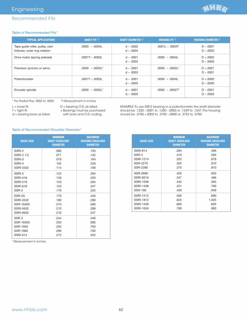
www.nhbb.com 62
Engineering
Recommended Fits
Table of Recommended Fits*
L = loose fit.T = tight fit.d = bearing bore as listed.
D = bearing O.D. as listed.+ Bearings must be purchased
with bore and O.D. coding.
EXAMPLE: To use SSR-2 bearing in a potentiometer, the shaft diameter should be .1250 –.0001 to .1250 –.0003 or .1249 to .1247. The housing should be .3750 +.0002 to .3750 –.0000 or .3752 to .3750.
* For Radial Play .0002 to .0005 ◊ Measurement in inches.
Table of Recommended Shoulder Diameter*
*Measurement in inches.
MINIMUM MAXIMUM BASIC SIZE SHAFT SHOULDER HOUSING SHOULDER DIAMETER DIAMETER
MINIMUM MAXIMUM BASIC SIZE SHAFT SHOULDER HOUSING SHOULDER DIAMETER DIAMETER
TYPICAL APPLICATIONS SHAFT FIT ◊ SHAFT DIAMETER ◊ HOUSING FIT ◊ HOUSING DIAMETER ◊
d – .0003 D – .0000
d – .0003 D – .0001
d – .0003 D – .0000
d – .0003 D – .0003
66844_Text.indd 64 11/16/12 9:45 AM
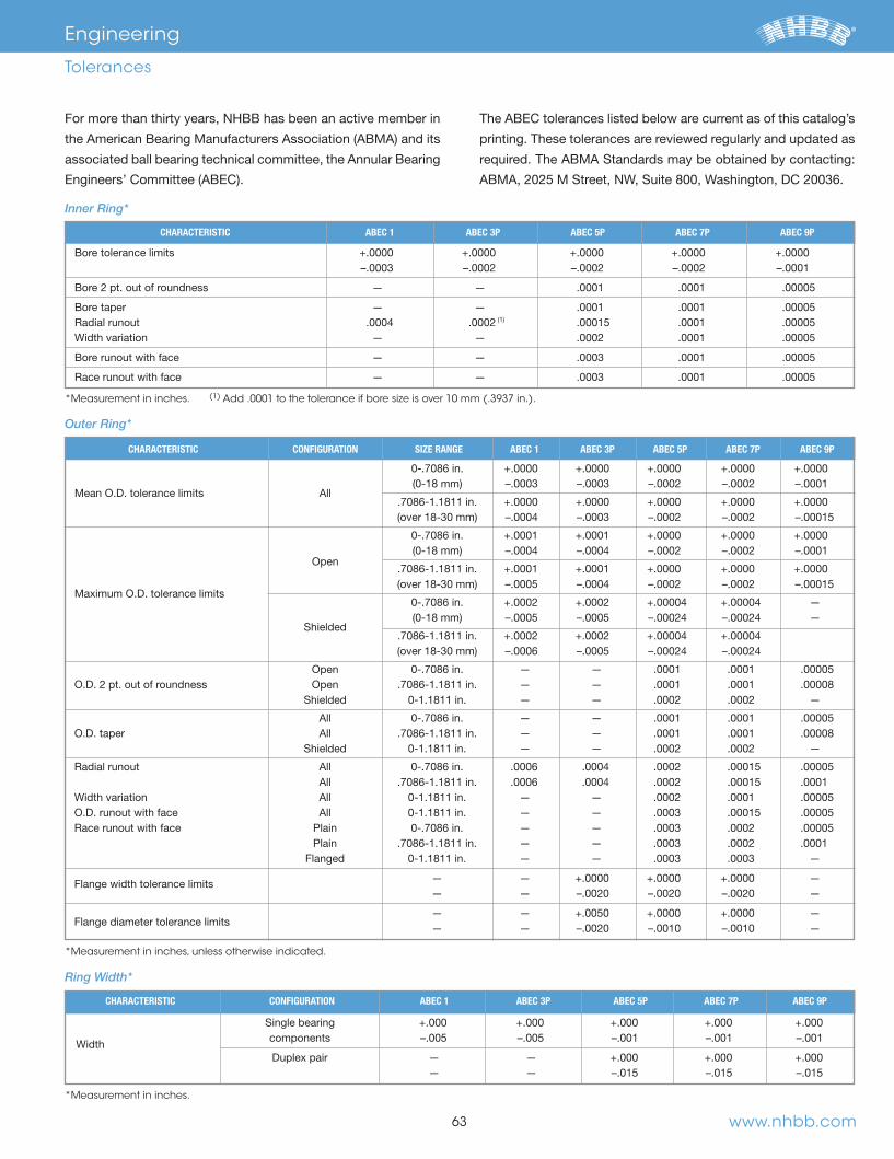
63
Engineering
Tolerances
For more than thirty years, NHBB has been an active member in
printing. These tolerances are reviewed regularly and updated as
CHARACTERISTIC ABEC 1 ABEC 3P ABEC 5P ABEC 7P ABEC 9P
–.0003 –.0002 –.0002 –.0002 –.0001
Bore 2 pt. out of roundness . — . — .0001 .0001 .00005
Bore taper . — . — .0001 .0001 .00005 .0002 .00015 .0001 .00005
Width variation . — . — .0002 .0001 .00005
Bore runout with face . — . — .0003 .0001 .00005
. — . — .0003 .0001 .00005
Inner Ring*
*Measurement in inches. (1) Add .0001 to the tolerance if bore size is over 10 mm (.3937 in.).
Outer Ring*
*Measurement in inches, unless otherwise indicated.
Ring Width*
*Measurement in inches.
CHARACTERISTIC CONFIGURATION SIZE RANGE ABEC 1 ABEC 3P ABEC 5P ABEC 7P ABEC 9P
Mean O.D. tolerance limits
Open
Maximum O.D. tolerance limits . — . —
. — . — .0001 .0001 .00005
. — .
. — . — .0002 .0002 . —
. — . — .0001 .0001 .00005
. — .
. — . — .0002 .0002 . —
. — . — .0002 .0001 .00005
. — . — .0003 .00015 .00005
. — . — .0003 .0002 .00005
. — . — .0003 .0002 .0001
. — . — .0003 .0003 . —
Flange width tolerance limits — . . — — . — –.0020 –.0020 –.0020 . —
Flange diameter tolerance limits
— . . — — . — –.0020 –.0010 –.0010 . —
www.nhbb.com
CHARACTERISTIC CONFIGURATION ABEC 1 ABEC 3P ABEC 5P ABEC 7P ABEC 9P
components –.005 –.005 –.001 –.001 –.001
Width
Duplex pair .— . .— .— –.015 –.015 –.015
66844_Text.indd 65 11/16/12 9:45 AM

www.nhbb.com 64
Engineering
Tolerances
-.0002 -.0003
OUTSIDE DIAMETER
-.0002
BORE DIAMETER RADIAL MEAN DIAMETER OVER INCL. RUNOUT TOLERANCE
Please refer to ABMA Standard #12 for more information.
-.0002 -.0002
-.0003
OUTSIDE DIAMETER
-.0002
-.0003
BORE DIAMETER RADIAL MEAN DIAMETER OVER INCL. RUNOUT TOLERANCE
-.001 -.015 -.005 -.020
BORE INNER RING SINGLE WIDTH DUPLEX WIDTH OVER INCL.
Please refer to ABMA Standard #12 for more information.
-.001 -.015 -.001 -.020
BORE INNER RING SINGLE WIDTH DUPLEX WIDTH OVER INCL.
ABEC 5T Tolerances ABEC 7T Tolerances
66844_Text.indd 66 11/16/12 9:45 AM

65 www.nhbb.com
Post Service Analysis
NHBB BASIC SIZE
TEST LOAD(THRUST)GRAMS
MAXIMUM STARTING TORQUEMILLIGRAM – MILLIMETERS
RADIAL PLAY
TIGHT FIT.0001" –.0003"
NORMAL FIT.0002" –.0005"
LOOSE FIT.0005" –.0008"
applications such as gyro gimbals, low power consumption
the total system should be evaluated in the design phase for
may be modified to reduce torque.
Maximum Starting Torque Values For ABEC 7P Bearings
Our precision miniature and instrument bearings have proven to
be highly reliable when used within the defined limits of their
capabilities. However, bearings, like any mechanical device, are
subject to failure. Failure may occur due to improper mounting,
lubrication, environment, loading, maintenance, or contamina-
tion after installation, as well as poor workmanship or material
deficiencies.
NHBB maintains a technical staff experienced in the analysis of
tools, and ultra-precision measuring and testing equipment, the
cause of bearing failure can often be determined. This capability
is available to customers experiencing bearing-related problems.
contact a NHBB sales representative who will make the necessary
arrangements.
The hardware and information required to successfully perform a
post-service analysis include:
bearing was used
under which the device operated, such as speed, loads,
temperature, and atmospheric conditions, as well as any
unusual shock, vibration, electrical arcing, or handling
situations to which the device was subjected
our findings will be provided.
Engineering
Torque
66844_Text.indd 67 11/16/12 9:45 AM

66www.nhbb.com
NHBB NMB TIMKEN (MPB) BARDEN MYONIC (RMB) ORIGINAL NHBB P/N
This chart is intended as a reference only. Users should consult with the listed manufacturers’ catalogs to establish dimensional interchangeability. Ball complements and load ratings may differ although dimensionally equivalent. NHBB cannot be held responsible for any errors contained herein.
Engineering
Interchange Chart
66844_Text.indd 68 11/16/12 9:45 AM

67 www.nhbb.com
NHBB NMB TIMKEN (MPB) BARDEN MYONIC (RMB) ORIGINAL NHBB P/N
This chart is intended as a reference only. Users should consult with the listed manufacturers’ catalogs to establish dimensional interchangeability. Ball complements and load ratings may differ although dimensionally equivalent. NHBB cannot be held responsible for any errors contained herein.
Engineering
Interchange Chart
66844_Text.indd 69 11/16/12 9:45 AM

68
0.0250 0.6350
1.0000
2.0000
3.0000
4.0000
5.0000
0.2362 6.0000
7.0000
0.3150 8.0000
9.0000
10.0000
11.0000
12.0000
13.0000
0.5512 14.0000
15.0000
16.0000
0.6500 16.5100
17.0000
18.0000
Engineering
Metric Conversion Table
19.0000
20.0000
21.0000
22.0000
23.0000
24.0000
25.0000
1.0236 26.0000
1.0630 27.0000
1.1025 28.0000
29.0000
30.0000
40.0000
www.nhbb.com
FRACTION INCH mm FRACTION INCH mm FRACTION INCH mm
66844_Text.indd 70 11/16/12 9:45 AM

Engineering
Temperature Conversion Table
www.nhbb.com 69
°C
60
66
110
116
121
132
160
166
°F/°C
100
110
120
130
140
150
160
170
180
190
200
210
220
230
240
250
260
270
280
290
300
310
320
330
340
350
360
370
380
390
°F
212
230
266
302
320
356
500
536
626
662
°C
210
216
221
232
260
266
310
316
321
332
360
366
°F/°C
400
410
420
430
440
450
460
470
480
490
500
510
520
530
540
550
560
570
580
590
600
610
620
630
640
650
660
670
680
690
°F
1022
1112
1130
1166
1202
1220
1256
°C
510
516
521
532
°F/°C
700
710
720
730
740
750
760
770
780
790
800
810
820
830
840
850
860
870
880
890
900
910
920
930
940
950
960
970
980
990
°F
1310
1526
1562
1616
1652
The numbers in the center column refer to the temperatures
either in Celsius or Fahrenheit which need conversion to the other
scale. When converting from Fahrenheit to Celsius, the equivalent
-
verting from Celsius to Fahrenheit, the answer will be found to
the right.
°C
-62
-51
-23
-16.1
-15.6
-15.0
-13.3
-12.2
-1.1
10
15.6
21.1
32.2
°F/°C
-110
-100
-90
-80
-70
-60
-50
-40
-30
-20
-10
0
1
2
3
4
5
6
7
8
9
10
20
30
40
50
60
70
80
90
°F
-166
-130
-112
-22
32
35.6
50.5
122
Celsius to Fahrenheit Conversion Table
66844_Text.indd 71 11/16/12 9:45 AM

www.nhbb.com 70
66844_Text.indd 72 11/16/12 9:45 AM
www.nhbb.com 71
New Hampshire Ball Bearings, Inc.
72 NHBB Overview
73 Astro Division, Laconia, NH
74 HiTech Division, Peterborough, NH
75 myonic USA, Chatsworth, CA
76 Minebea Co., Ltd.
66844_Text.indd 73 11/16/12 9:45 AM

www.nhbb.com 72
New Hampshire Ball Bearings, Inc.
NHBB Overview
Committed to Excellence
We continue to build strong alliances within the aerospace, defense, dental, medical, and
high technology markets, working across the enterprise to provide business solutions
that keep pace with our customers’ technological advances.
The precision tolerances required by the customers we support necessitate a complete
an investment in advanced capabilities, to real-time quality control, to continuous
improvement in both processes and people. Our commitment to manufacturing excel-
lence is seen time and again in our high level of service and product quality.
Applications Engineering
Knowing how to leverage knowledge, industry experience, emerging technology, and
industry trends is the true differentiator when it comes to customized bearing assem-
product’s life cycle, and we do this with a passion for serving as a valued technical
resource to our customers.
Manufacturing
-
tage in precision manufacturing. We’re able to guarantee the close tolerances necessary
in life-critical and high speed applications, as well as address manufacturing challenges
in-house through new tools, precision gages, and state-of-the-art production processes.
Care for the Environment
regulatory compliance, and continuous improvement aimed at reducing the
impact of every phase of the manufacturing process. Our objectives also include the
promotion of environmental awareness among employees and within our communities.
66844_Text.indd 74 11/16/12 9:45 AM

www.nhbb.com 73
New Hampshire Ball Bearings, Inc.
Astro Division, Laconia, NH
PRODUCTS
Bushings
Custom-lined parts
Next-up assemblies & machined parts
NMB, KARUIZAWA, JAPAN*
Next-up assemblies & machined parts
QUALITY CERTIFICATIONS
NADCAP
ENVIRONMENTAL MANAGEMENT CERTIFICATION
significant engineering expertise and specialty materials. Our stringent process controls and advanced planning system
enable us to satisfy unique production requirements and provide improved delivery scheduling as part of our continuous
improvement culture and commitment to customer satisfaction.
giving customers access to a global supply of high quality commercial aerospace parts.
66844_Text.indd 75 11/16/12 9:45 AM
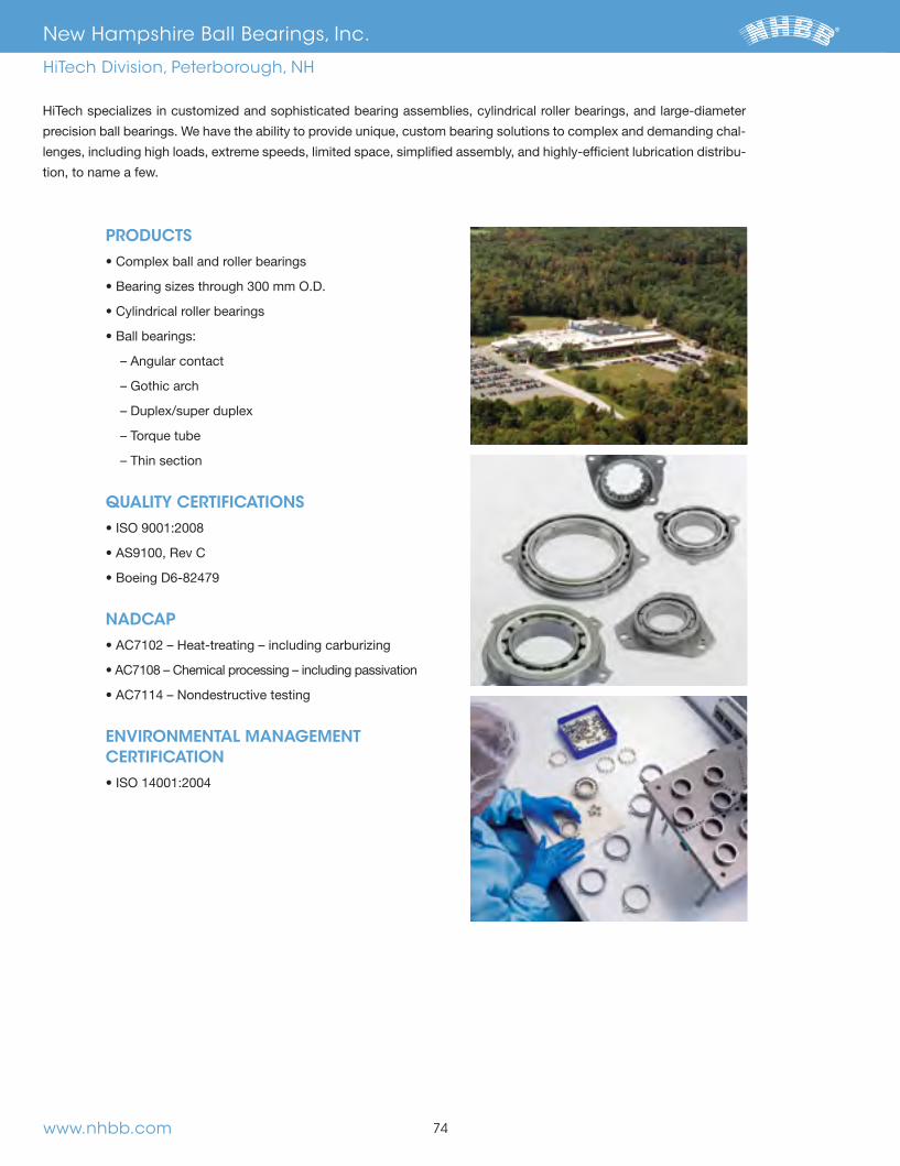
www.nhbb.com 74
New Hampshire Ball Bearings, Inc.
HiTech Division, Peterborough, NH
PRODUCTS
– Gothic arch
– Torque tube
– Thin section
QUALITY CERTIFICATIONS
NADCAP
ENVIRONMENTAL MANAGEMENT CERTIFICATION
HiTech specializes in customized and sophisticated bearing assemblies, cylindrical roller bearings, and large-diameter
precision ball bearings. We have the ability to provide unique, custom bearing solutions to complex and demanding chal-
lenges, including high loads, extreme speeds, limited space, simplified assembly, and highly-efficient lubrication distribu-
tion, to name a few.
66844_Text.indd 76 11/16/12 9:45 AM
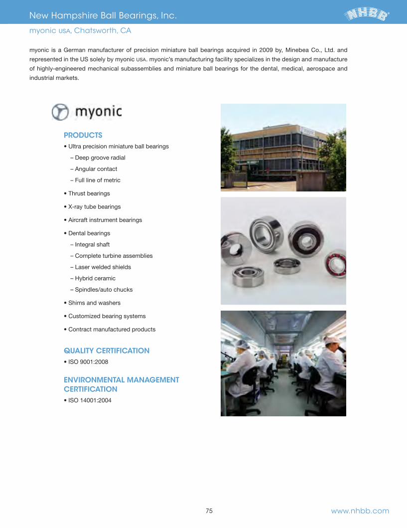
www.nhbb.com 75
New Hampshire Ball Bearings, Inc.
myonic USA, Chatsworth, CA
PRODUCTS
– Deep groove radial
– Full line of metric
– Complete turbine assemblies
– Hybrid ceramic
QUALITY CERTIFICATION
ENVIRONMENTAL MANAGEMENT CERTIFICATION
. myonic’s manufacturing facility specializes in the design and manufacture
of highly-engineered mechanical subassemblies and miniature ball bearings for the dental, medical, aerospace and
industrial markets.
66844_Text.indd 77 11/16/12 9:45 AM

www.nhbb.com 76
New Hampshire Ball Bearings, Inc.
The Minebea Group of Companies
New Hampshire Ball Bearings and myonic are an integral part of an international business, the Minebea Group of
precision components for the telecommunications, aerospace, automotive, and electrical appliance industries.
its worldwide manufacturing capabilities, Minebea’s vision is to lead the competition through manufacturing and
technological excellence.
66844_Text.indd 78 11/16/12 9:45 AM
NH
BB
P
REC
ISION
DIV
ISION
: Prod
uc
ts an
d En
gin
ee
ring
Precision Division andCorporate Headquarters9700 Independence Avenue
Chatsworth, CA 91311 tel: 818.993.4100 fax: 818.407.5020
Astro Division 155 Lexington Drive Laconia, NH 03246
tel: 603.524.0004 fax: 603.524.9025
HiTech Division 175 Jaffrey Road
Peterborough, NH 03458 tel: 603.924.4100 fax: 603.924.4419
myonic USA
9700 Independence AvenueChatsworth, CA 91311
tel: 818.701.4833 fax: 818.407.5020
NHBB Europe
Siemensstrasse 30 63225 Langen
Germany tel: (49) 6103.913.341 fax: (49) 6103.913.342
www.nhbb.com
© 2012 NHBB, Inc.
PRECISION DIVISIONProducts and Engineering
Miniature and Instrument
Torque Tube and Thinex
Custom Specialty
Bearing Assemblies
Middle Size Bearings
66844_Cov.indd 1 11/7/12 3:09 PM