ke-484c instruction manual - brother
TRANSCRIPT

KE-484C
Please read this manual before using the machine.
Please keep this manual within easy reach for quick reference.
ELECTRONIC LOCKSTITCH PATTERN TACKER WITH TREBLE HOOK
INSTRUCTION MANUAL

iKE-484C
Thank you very much for buying a BROTHER sewing machine. Before using your new machine, please read the safety
instructions below and the explanations given in the instruction manual.
With industrial sewing machines, it is normal to carry out work while positioned directly in front of moving parts such as the
needle and thread take-up lever, and consequently there is always a danger of injury that can be caused by these parts.
Follow the instructions from training personnel and instructors regarding safe and correct operation before operating the
machine so that you will know how to use it correctly.
SAFETY INSTRUCTIONS
1. Safety indications and their meaningsThis instruction manual and the indications and symbols that are used on the machine itself are provided in order to ensure
safe operation of this machine and to prevent accidents and injury to yourself or other people.
The meanings of these indications and symbols are given below.
Indications
DANGER The instructions which follow this term indicate situations where failure to follow theinstructions will almost certainly result in death or severe injury.
CAUTIONThe instructions which follow this term indicate situations where failure to follow theinstructions could cause injury when using the machine or physical damage to equipmentand surroundings.
Symbols
··········· This symbol ( ) indicates something that you should be careful of. The picture inside the triangleindicates the nature of the caution that must be taken.(For example, the symbol at left means “beware of injury”.)
··········· This symbol ( ) indicates something that you must not do.
··········· This symbol ( ) indicates something that you must do. The picture inside the circle indicates thenature of the thing that must be done.(For example, the symbol at left means “you must make the ground connection”.)

ii KE-484C
2. Notes on safety
DANGER
Wait at least 5 minutes after turning off the power switch and disconnecting the power cord from the wall outlet beforeopening the face plate of the control box. Touching areas where high voltages are present can result in severe injury.
��CAUTION
Environmental requirements
Use the sewing machine in an area which is free fromsources of strong electrical noise such as high-frequency welders.Sources of strong electrical noise may cause prob-lems with correct operation.
Any fluctuations in the power supply voltage should
be within �10% of the rated voltage for the machine.Voltage fluctuations which are greater than this maycause problems with correct operation.
The power supply capacity should be greater than therequirements for the sewing machine’s electricalconsumption.Insufficient power supply capacity may cause prob-lems with correct operation.
The pneumatic delivery capability should be greaterthan the requirements for the sewing machine’s totalair consumption.Insufficient pneumatic delivery capability may causeproblems with correct operation.
The ambient temperature should be within the range
of 5�C to 35�C during use.Temperatures which are lower or higher than this maycause problems with correct operation.
The relative humidity should be within the range of45% to 85% during use, and no dew formation shouldoccur in any devices.Excessively dry or humid environments and dew for-mation may cause problems with correct operation.
Avoid exposure to direct sunlight during use.Exposure to direct sunlight may cause problems withcorrect operation.
In the event of an electrical storm, turn off the powerand disconnect the power cord from the wall outlet.Lightning may cause problems with correct operation.
Installation
Machine installation should only be carried out by aqualified technician.
Contact your Brother dealer or a qualified electricianfor any electrical work that may need to be done.
The sewing machine weighs more than 56 kg. Theinstallation should be carried out by two or morepeople.
Do not connect the power cord until installation iscomplete, otherwise the machine may operate if thefoot switch is depressed by mistake, which couldresult in injury.
Hold the machine head with both hands when tilting itback or returning it to its original position.Furthermore, after tilting back the machine head, donot push the face plate side or the pulley side fromabove, as this could cause the machine head totopple over, which may result in personal injury ordamage to the machine.
Be sure to connect the ground. If the ground connec-tion is not secure, you run a high risk of receiving aserious electric shock, and problems with correctoperation may also occur.
All cords should be secured at least 25 mm away fromany moving parts. Furthermore, do not excessivelybend the cords or secure them too firmly with staples,otherwise there is the danger that fire or electricshocks could occur.
Install the belt covers to the machine head and motor.
If using a work table which has casters, the castersshould be secured in such a way so that they cannotmove.
Be sure to wear protective goggles and gloves whenhandling the lubricating oil and grease, so that they donot get into your eyes or onto your skin, otherwiseinflammation can result.Furthermore, do not drink the oil or eat the greaseunder any circumstances, as they can cause vomitingand diarrhoea.Keep the oil out of the reach of children.

iiiKE-484C
CAUTION
Sewing
This sewing machine should only be used by opera-tors who have received the necessary training in safeuse beforehand.
The sewing machine should not be used for anyapplications other than sewing.
Be sure to wear protective goggles when using themachine.If goggles are not worn, there is the danger that if aneedle breaks, parts of the broken needle may enteryour eyes and injury may result.
Set the needle to the needle up stop position beforeturning off the power.If this is not done, the wiper may strike the needle,which might cause the needle to break.
Turn off the power switch at the following times,otherwise the machine may operate if the foot switchis depressed by mistake, which could result in injury.
� When threading the needle
� When replacing the needle and bobbin
� When not using the machine and when leaving themachine unattended
If using a work table which has casters, the castersshould be secured in such a way so that they cannotmove.
Attach all safety devices before using the sewingmachine. If the machine is used without these devicesattached, injury may result.
Do not touch any of the moving parts or press anyobjects against the machine while sewing, as this mayresult in personal injury or damage to the machine.
If an error occurs in machine operation, or if abnormalnoises or smells are noticed, immediately turn off thepower switch. Then contact your nearest Brotherdealer or a qualified technician.
If the machine develops a problem, contact yournearest Brother dealer or a qualified technician.
Cleaning
Set the needle to the needle up stop position beforeturning off the power.If this is not done, the wiper may strike the needle,which might cause the needle to break.
Turn off the power switch before carrying outcleaning, otherwise the machine may operate if thefoot switch is depressed by mistake, which couldresult in injury.
Be sure to wear protective goggles and gloves whenhandling the lubricating oil and grease, so that they donot get into your eyes or onto your skin, otherwiseinflammation can result.Furthermore, do not drink the oil or eat the grease un-der any circumstances, as they can cause vomitingand diarrhoea.Keep the oil out of the reach of children.
Maintenance and inspection
Maintenance and inspection of the sewing machineshould only be carried out by a qualified technician.
Ask your Brother dealer or a qualified electrician tocarry out any maintenance and inspection of theelectrical system.
Set the needle to the needle up stop position beforeturning off the power.If this is not done, the wiper may strike the needle,which might cause the needle to break.
Turn off the power switch and disconnect the powercord from the wall outlet at the following times,otherwise the machine may operate if the foot switchis depressed by mistake, which could result in injury.
� When carrying out inspection, adjustment and main-tenance
� When replacing consumable parts such as the ro-tary hook
Disconnect the air hoses from the air supply and waitfor the needle on the pressure gauge to drop to “0”before carrying out inspection, adjustment and repairof any parts which use the pneumatic equipment.
If the power switch and air need to be left on whencarrying out some adjustment, be extremely careful toobserve all safety precautions.
Hold the machine head with both hands when tilting itback or returning it to its original position.Furthermore, after tilting back the machine head, donot push the face plate side or the pulley side fromabove, as this could cause the machine head totopple over, which may result in personal injury ordamage to the machine.
Use only the proper replacement parts as specified byBrother.
If any safety devices have been removed, be abso-lutely sure to re-install them to their original positionsand check that they operate correctly before using themachine.
Any problems in machine operation which result fromunauthorized modifications to the machine will not becovered by the warranty.
iv KE-484C
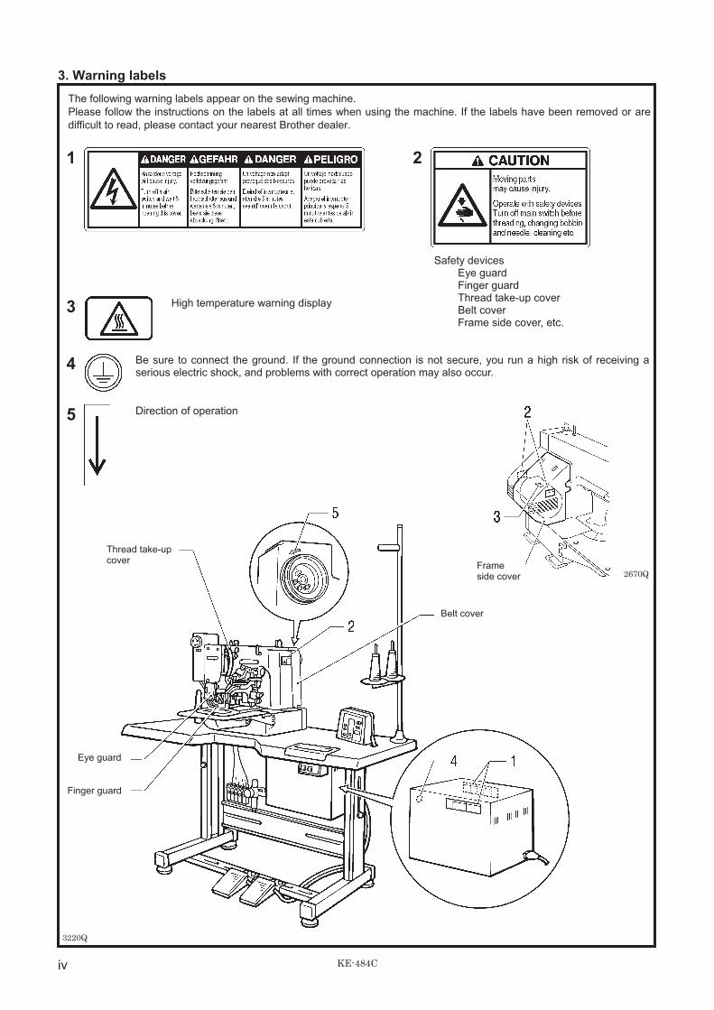
3. Warning labels
The following warning labels appear on the sewing machine.
Please follow the instructions on the labels at all times when using the machine. If the labels have been removed or are
difficult to read, please contact your nearest Brother dealer.
1 2
3 High temperature warning display
Safety devicesEye guardFinger guardThread take-up coverBelt coverFrame side cover, etc.
4 Be sure to connect the ground. If the ground connection is not secure, you run a high risk of receiving aserious electric shock, and problems with correct operation may also occur.
5 Direction of operation
3220Q
Finger guard
Eye guard
Thread take-upcover
Belt cover
2670QFrameside cover
KE-484C
CONTENTS
1. NAME OF EACH PART............................... 1
2. SPECIFICATIONS ....................................... 2
2-1. Specifications ......................................................... 2
3. INSTALLATION ........................................... 3
3-1. Power table............................................................. 3
3-2. Installing the control box......................................... 4
3-3. Installing the rubber cushions ................................. 5
3-4. Installing the oil pan................................................ 5
3-5. Installing the cushions ............................................ 5
3-6. Installing the switching plate ................................... 6
3-7. Installing the machine head .................................... 6
3-8. Installing the head rest ........................................... 7
3-9. Installing the operation panel.................................. 7
3-10. Connecting the ground wire.................................. 8
3-11. Connecting the cords............................................ 9
3-12. Piping ..................................................................12
3-13. Installing the belt cover ........................................15
3-14. Installing the foot switch.......................................15
3-15. Installing the needle sub plate .............................16
3-16. Installing the spool stand .....................................17
3-17. Installing the eye guard........................................17
4. LUBRICATION............................................ 18
4-1. Lubrication points ..................................................18
5. OPERATION............................................... 19
5-1. Name and function of each operation panel item ......19
5-2. Operating procedure..............................................21
5-3. Operating the foot switch .......................................22
5-4. Operating the emergency stop switch....................23
5-5. Operating the thread wiper switch ........................23
6. CHECKING THE SEWING PATTERN........ 24
7. CORRECT USE.......................................... 25
7-1. Installing the needle...............................................25
7-2. Threading the upper thread ...................................25
7-3. Winding the lower thread.......................................26
7-4. Replacing the bobbin case and
threading the thread ..............................................27
7-5. Thread tension.......................................................27
8. SEWING ..................................................... 30
9. MAINTENANCE AND INSPECTION.......... 31
9-1. Checking the needle..............................................31
9-2. Cleaning the rotary hook........................................31
9-3. Lubrication.............................................................32
9-4. Draining the oil.......................................................33
9-5. Cleaning the control box air inlet port ....................33
9-6. Cleaning the air holes of belt cover
and frame side cover.............................................33
9-7. Cleaning the eye guard..........................................33
10. STANDARD ADJUSTMENTS................... 34
10-1. Adjusting the needle bar height ...........................34
10-2. Adjusting the needle bar lift amount .................... 34
10-3. Adjusting the needle clearance ........................... 35
10-4. Adjusting the thread take-up amount .................. 35
10-5. Adjusting the movable knife ................................ 36
10-6. Adjusting the work clamp lift amount................... 38
10-7. Work clamp interchangeability ............................ 39
10-8. Adjusting the needle up stop position.................. 39
10-9. Adjusting the thread wiper................................... 40
10-10. Adjustment of air pressure ................................ 40
10-11. Checking the input sensor and DIP switch input..... 41
10-12. Checking the input voltage................................ 42
10-13. Clearing all memory settings............................. 42
10-14. Moving stitch patterns ....................................... 43
11. USING THE COUNTERS ..........................44
11-1. Using the bobbin thread counter ......................... 44
11-2. Using the production counter .............................. 44
12. CHANGING FUNCTIONS USINGTHE DIP SWITCHES.................................45
12-1. Operation panel DIP switches ............................. 45
12-2. DIP switches inside the control box..................... 46
12-3. Using user programs........................................... 47
13. CHANGING SPECIAL FUNCTIONSUSING THE MEMORY SWITCHES......... 49
13-1. Using the cycle sewing function .......................... 52
14. SETTING THE WORK CLAMP MODE .....54
14-1. Light work clamp ................................................. 55
15. TABLE OF ERROR CODES .....................56
16. TROUBLESHOOTING ..............................58
17. OPTIONAL PARTS ...................................61

1. NAME OF EACH PART
1 KE-484C
1. NAME OF EACH PART
3157Q
(1) Power switch(2) Control box(3) Operation panel(4) Foot switch(5) Motor(6) EMERGENCY STOP switch(7) Pulley(8) Spool stand(9) Thread take-up lever(10) Thread wiper switch
3212Q
Safety devices;(11) Finger guard(12) Eye guard(13) Thread take-up cover(14) Belt cover(15) Frame side cover

2. SPECIFICATIONS
2KE-484C
2. SPECIFICATIONS
2-1. Specifications
Main use Seat Belt
Stitch formation Single needle lock stitch
Maximum sewing speed 2,200 rpm (Pitch 3 mm)
Maximum pattern size 100 ���60 mm max.
Feed mechanism R-� �intermittent feed mechanism (pulse-motor driven mechanism)
Stitch length 0.1 - 10.0 mm
Number of stitches Variable
Maximum stitch number 20,000 stitches (including 10,000 stitches which can be added)
Work clamp lifter Pneumatic type
Work clamp height 25 mm max.
Rotary hook Treble hook
Needle DP���17 #25
Wiper device Standard equipment
Thread trimmer device Standard equipment
Thread take-up device Standard equipment
Safety device built-in stopping mechanism
Data storage method P-ROM (Any sewing pattern can be added using PS-3000.)
Number of user programs 16
Number of cycle programs 4
Number of stored dataUp to 100 patterns can be added. Total number of stitches of stored data
which can be added is within 10,000.
Motor Three-phase 400W induction motor
WeightsMachine head: 56 kg, Operation panel: 0.6 kg,
Control box: 9 - 19 kg (depending on destination)
Power sourceSingle-phase 110, 220 - 230, 240V
3-phase 220-230, 380, 400VMaximum electric power consumption; 600VA
If you want to sew a pattern, you can create your original pattern using the PS-3000.Consult with your local Brother Sales Office for details.
Note when creating additional dataWhen sewing data with a small number of stitches (15 stitches or less) is sewn repeatedly (short cycle operation), the uppershaft motor may overheat and the “E-20” error code may be generated.

3. INSTALLATION
3 KE-484C
3. INSTALLATION
CAUTIONMachine installation should only be carried out by aqualified technician.
Contact your Brother dealer or a qualified electricianfor any electrical work that may need to be done.
The sewing machine head weighs more than 56 kg.The installation should be carried out by two or morepeople.
Do not connect the power cord until installation iscomplete, otherwise the machine may operate if thefoot switch is depressed by mistake, which couldresult in injury.
Hold the machine head with both hands when tilting itback or returning it to its original position.Furthermore, after tilting back the machine head, donot push the face plate side or the pulley side fromabove, as this could cause the machine head totopple over, which may result in personal injury ordamage to the machine.
All cords should be secured at least 25 mm away fromany moving parts. Furthermore, do not excessivelybend the cable or secure it too firmly staples,otherwise there is the danger that fire or electricshocks could occur.
Be sure to connect the ground. If the groundconnection is not secure, you run the risk of receivinga serious electric shock, and problems with correctoperation may also occur.
Install the belt covers to the machine head and motor.
3-1. Power table
Model code� Use the power table which has been specially designed for each
sewing machines.* If using a commercially-available table, process it as shown in
the illustration below.Table/ legs assembly 127-V30-50001
Note:The thickness of the table should be at least 40 mm, and it should be strong enough to bear the weight and vibration of thesewing machine.If the distance A between the insides of the legs is less than 740 mm, move the control box installation position to the left (B= 247 mm).Check that the control box is at least 10 mm away from the leg. If the control box and leg are touching, it could cause thesewing machine to operate incorrectly.
2739Q
3. INSTALLATION
4KE-484C
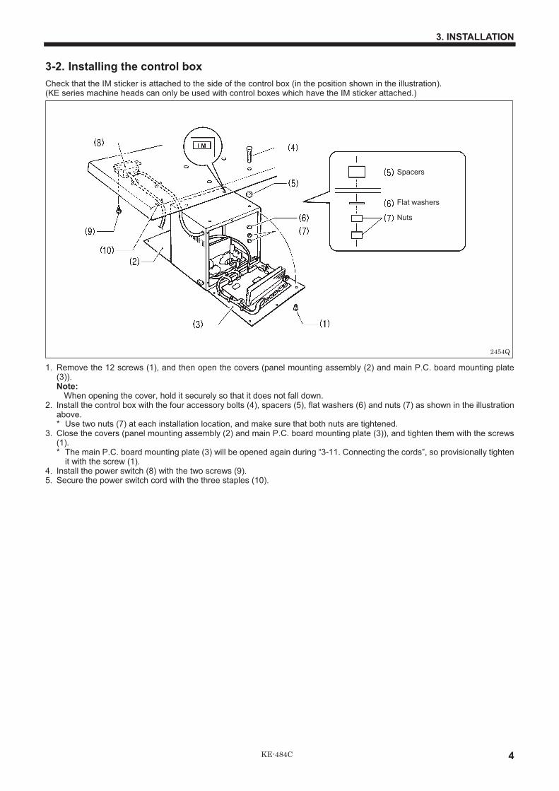
3-2. Installing the control box
Check that the IM sticker is attached to the side of the control box (in the position shown in the illustration).(KE series machine heads can only be used with control boxes which have the IM sticker attached.)
1. Remove the 12 screws (1), and then open the covers (panel mounting assembly (2) and main P.C. board mounting plate(3)).Note:
When opening the cover, hold it securely so that it does not fall down.2. Install the control box with the four accessory bolts (4), spacers (5), flat washers (6) and nuts (7) as shown in the illustration
above.* Use two nuts (7) at each installation location, and make sure that both nuts are tightened.
3. Close the covers (panel mounting assembly (2) and main P.C. board mounting plate (3)), and tighten them with the screws(1).* The main P.C. board mounting plate (3) will be opened again during “3-11. Connecting the cords”, so provisionally tighten
it with the screw (1).4. Install the power switch (8) with the two screws (9).5. Secure the power switch cord with the three staples (10).
2454Q
Spacers
Flat washers
Nuts

3. INSTALLATION
5 KE-484C
3-3. Installing the rubber cushions
Install the rubber cushions (1) with the nails (2).* Install so that the head of the nail does not protrude from the
rubber surface
3-4. Installing the oil pan
1. Insert the tabs of the oil pan (2) into the holes for thecushions (1), and then secure it in place with the five nails(3) so that the oil pan (2) is not at an angle.
2. While pushing the oil pan (2) down from above, screw in theoil container (4).
3-5. Installing the cushions
Place the two cushions (1) into the holes in the work table sothat the notches are aligned with the tabs in the oil pan, andsecure them in place with the nails (2).
2489Q
2492Q
2491Q
2490Q

3. INSTALLATION
6KE-484C
3-6. Installing the switching plate
Install the switching plate (1) to the work table with the two woodscrews (2) in the position shown in the illustration.* The switching plate and the switch bracket which is attached to
the machine head prevent the sewing machine from startingwhen the machine head is tilted back. Therefore, this meansthat the sewing machine will not start if the switching plate isnot installed.
3-7. Installing the machine head
1. Insert the head hinges (1) into the machine head so that they are parallel, and then secure them with the two set screws (2).2. Place the machine head gently on top of the rubber cushions (3) and cushions (4).
Note:Pull the cords (5) out as shown in the illustration above in order to prevent them from being clamped by the machine head.
3. Install the hinge presser (6) with the two bolts and two nuts.4. Check that the head position switch is turned on as shown in Figure 1.5. Connect the motor cord connector (7) to the accessory cord connector (8).
2493Q
2494Q
2495Q 2496Q
Fig. 1
3. INSTALLATION
7 KE-484C
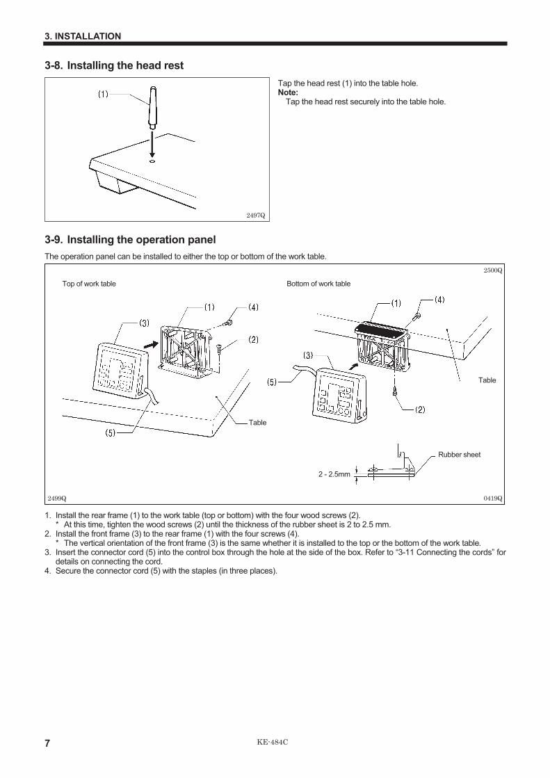
3-8. Installing the head rest
Tap the head rest (1) into the table hole.Note:
Tap the head rest securely into the table hole.
3-9. Installing the operation panel
The operation panel can be installed to either the top or bottom of the work table.
1. Install the rear frame (1) to the work table (top or bottom) with the four wood screws (2).* At this time, tighten the wood screws (2) until the thickness of the rubber sheet is 2 to 2.5 mm.
2. Install the front frame (3) to the rear frame (1) with the four screws (4).* The vertical orientation of the front frame (3) is the same whether it is installed to the top or the bottom of the work table.
3. Insert the connector cord (5) into the control box through the hole at the side of the box. Refer to “3-11 Connecting the cords” fordetails on connecting the cord.
4. Secure the connector cord (5) with the staples (in three places).
2497Q
2499Q
2500Q
0419Q
Top of work table Bottom of work table
Table
Table
Rubber sheet
2 - 2.5mm

3. INSTALLATION
8KE-484C
3-10. Connecting the ground wire
CAUTION
Be sure to connect the ground. If the ground connection is not secure, you run the risk of receiving a serious electric shock,and problems with correct operation may also occur.
2741Q
Connect to the power switch. However, theblack wire is insulated to the inside of thebox and is not used.
Connect to ground

3. INSTALLATION
9 KE-484C
3-11. Connecting the cords
3221Q
2502Q 2503Q 2504Q

3. INSTALLATION
10KE-484C
1. Gently tilt back the machine head.Note:
After tilting back the machine head, do not push the face side or the pulley side from above.2. Pass the cord bundle (1) from the machine head through the hole (2) in the work table.3. Gently return the machine head to its original position.4. Remove the six screws (3), and then open the control box cover (main P.C. board mounting plate (4)).
Note:When opening the cover, hold it securely so that it does not fall down.
5. Loosen the two screws (5), and then open the cord presser plate (6) in the direction of the white arrow and pass the cord bundle(1) through the opening.
6. Remove the screw (7), and then pass it through the terminal holes in the ground cord (8) from the machine head and the groundcord (9) from the operation panel. Then re-tighten the screw (7) so that the ground cords (8) and (9) are secured as shown in theillustration.
7. Remove the screw (10) , and then pass it through the terminal hole in the ground cord (11) from the upper shaft motor. Then re-tighten the screw (10) so that the ground cord (11) is secured as shown in the illustration.Note:
Make sure that the ground connections are secure in order to ensure safety.8. Securely connect connectors P1 to P8, P11, P14 and P18 as indicated in the table below.
Note:Check that the connector is facing the correct way, and then insert it firmly until it locks into place.Furthermore, lock the cord clamp at the top.
Machine head connectors
Connection location No. of pins Cord mark
Connection locationon circuit board
Cord clamps used
Head position switch 9-pin [1A] P1 - A (ORG1) None
X, Y sensor 12-pin [1] P1 - B (ORG2) None
Synchronizer 5-pin [2] P2 (SYNCHRO) (G)
Machine specificationselect connector
8-pin [3] P3 (SELECT) None
Thread trimmer solenoid 4-pin [5] P5 (SOL) (G) (H)
Pulse motor, Y 4-pin (blue) [6] P6 (YPM) (G) (H)
Pulse motor, X 4-pin [7] P7 (XPM) (G) (H)
Operation panel 26-pin None P8 (PANEL) None
Upper shaft motor 3-pin None P11 (UVW) (A)(B)(C)(D)(E)(F)
EMERGENCY STOP switch 6-pin [18] P18 (HEAD) None
Solenoid valve 12-pin None P14 (AIR) (A)(B)(C)(D)
9. Secure the cord bundle (1) with the cord clamps (12) and (13).10. Close the cord presser plate (6) in the direction of the black arrow, and secure it by tightening the screws (5).
Note:Check that the cords do not get pulled when the machine head is tilted back gently.

3. INSTALLATION
11 KE-484C
11. Replace PROM control assembly with one which contains sewing data.1) Use the special tool to remove the PROM control assembly (14) from the PROM socket (15).
* Store the removed PROM control assembly in the special case provided.2) Bend the pins of the PROM control assembly which contains sewing data (16) so that they are at an angle of approximately
90°.3) Make the directions of the PROM control assembly (16) and the PROM socket (15) same so that the portions (a) come on the
same side, and press the PROM gently into the socket while checking that the pins of the PROM are going into the socketproperly.
Note:� If the PROM has been replaced, press the RESET switch (17) while turning on the power in order to initialize the memory.
All of the user programs, cycle programs and memory switches which have been recorded will then be cleared.� The PROM which is installed at the time of shipment from the factory does not include any sewing data. If you try to change
the program number without replacing the PROM, error “E-b1” will be displayed.To create sewing data, use the PS-3000 electronic pattern sewer/reader (sold separately).
12. Tighten the cover (main P.C. board mounting plate (4)) with the six screws (3).Note:
Check that the cords do not come into contact with the fan (18) and that they are not clamped by the cover at this time.
Note:Check that the main PROM ( * ) is version MN-L or later.
2479Q
2544Q 2597Q
2595Q 2596Q
3. INSTALLATION
12 KE-484C
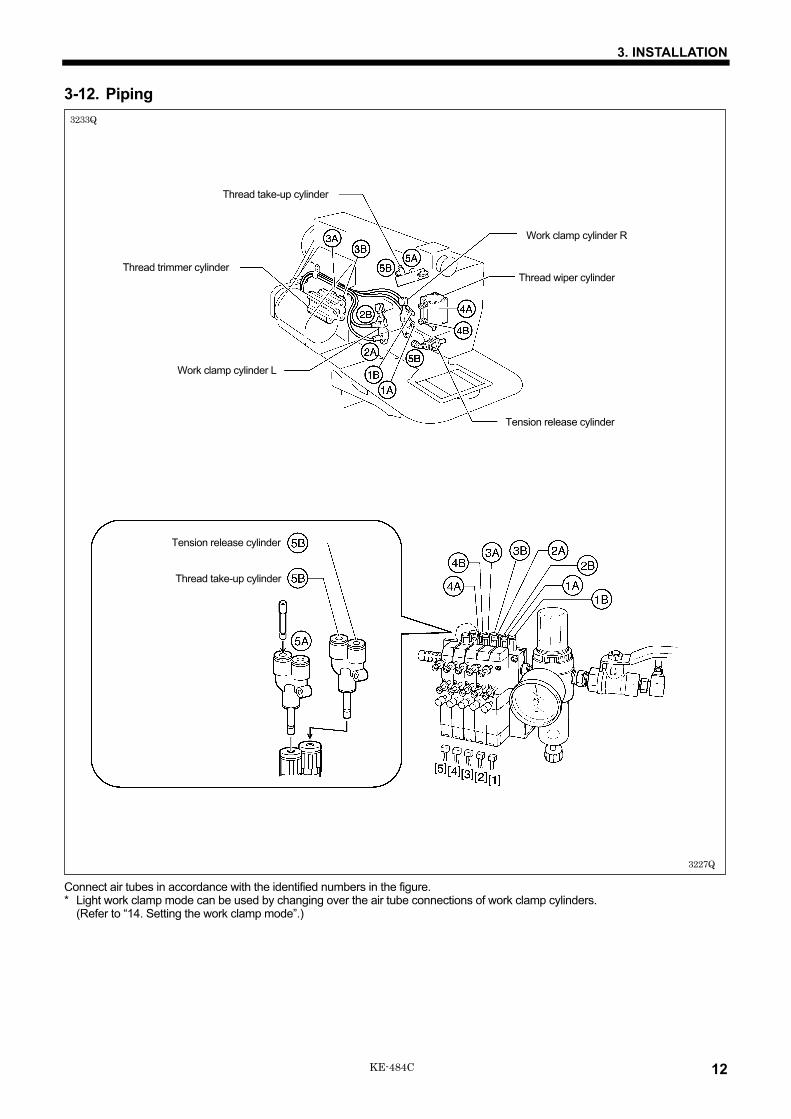
3-12. Piping
Connect air tubes in accordance with the identified numbers in the figure. * Light work clamp mode can be used by changing over the air tube connections of work clamp cylinders.
(Refer to “14. Setting the work clamp mode”.)
Thread trimmer cylinder
Thread take-up cylinder
Work clamp cylinder R
Work clamp cylinder L
Tension release cylinder
Thread wiper cylinder
3233Q
3227Q
Tension release cylinder
Thread take-up cylinder

3. INSTALLATION
13 KE-484C
3-12-1. Installing the air unitMake sure that the air unit does not touch the control box or the work table leg.
<When installing to the underside of the work table>1. Remove the two screws (1) and the valve setting plate (2).2. Turn the valve setting plate (2) upside down, and install it to the underside of the work table using the two wood screws (3) and
washers (4) which are provided as accessories.* At this time, install the valve setting plate (2) in a position where it will not be in the way when using the machine. (The
recommended installation position is shown in Figure 1.)3. Install the ground cord (5) to the machine head.4. Install the air unit (6) to the valve setting plate (2) with two screws (1).5. Connect the air hose (7).6. Adjust the air pressure. (Refer to “10-10. Adjusting the air pressure”.)
<When installing to a beam>1. Make holes in the beam as shown in the illustration above. (Button hole diameter is 5.4 mm. The pitch is 50 mm.)2. Install the air unit (8) to the beam with two accessory screws (9) and two bolts (10).3. Install the ground cord (11) to the machine head.4. Connect the air hose (12).5. Adjust the air pressure. (Refer to “10-10. Adjusting the air pressure”.)
3161Q 1093Q
2598Q 3162Q
Fig. 1

3. INSTALLATION
14 KE-484C
3-12-2. Connecting the thread wiper switch
Connect the thread wiper switch (1) to the solenoid valve as shown in the figure.
3-12-3. Adjusting the speed controller
The speeds at which the work clamps and other devices operate can be adjusted by loosening or tightening the valve control knobs. The speeds should be adjusted to speeds which are suitable for the intended application. When the power is turned off, the operation of the devices can be checked by pressing the switches. 1. Work clamp (Valve 1 and 2)
Adjust the control knobs so that the left and right work clamps both operate at the same speed. * If the upper control knob is tightened, the raising speed becomes slower; if it is loosened, the raising speed becomes faster. * If the lower control knob is tightened, the lowering speed becomes slower; if it is loosened, the lowering speed becomes faster.
2. Thread trimmer (Valve 3) Fully open the upper and lower control knobs. Then turn the lower control knob to adjust the thread trimming speed as required.
3. Thread wiper (Valve 4) Fully open the upper and lower control knobs.
4. Tension release and thread take-up (Valve 5) Fully open the upper and lower control knobs.
3163Q
Upper knob
Lower knob
Switch
Yellow
3232Q3231Q

3. INSTALLATION
15 KE-484C
3-13. Installing the belt cover
1. Loosen the screw (2) of the upper cover (1).2. Insert the belt cover (3) in the direction of the arrow, and then
secure it with the two screws (2) and the two screws (4).Check that the cords do not get clamped by the belt cover atthis time.
* It is not necessary to remove the belt cover (3) when tiltingback the machine head.
3-14. Installing the foot switch
1. Insert the connector of the foot switch (3) into the connector (2) of the control box (1).2. Install the foot switch (3) to the work table leg (12) with foot switch support plate A (4), foot switch support plate C (5), the bolt (6),
spring washer (7), flat washer (8), bolt (9), spring washer (10) and flat washer (11) as shown in Figure A.
If foot switch support plate B (13) is used in a back-to-front position, it can be used as shown in Figure B.1. Remove the screw (14) and rubber plug (15).
* Note that the spring (16) will come out when the screw (14) is removed.2. Turn foot switch support plate B (13) back to front, and then install it with the bolt (17), spring washer (18) and flat washer (19) as
shown in Figure B.Note:
If using the foot switch without installing it to the work table leg, move the foot switch at least 10 mm away from the leg. If thefoot switch is not fully in contact with the work table leg when the foot switch is used, for example, if it is just hooked loosely ontothe work table leg, it may cause the sewing machine to operate incorrectly.
2456Q
2508Q
2507Q
2683Q
[A]
[B]

3. INSTALLATION
16KE-484C
3-15. Installing the needle sub plate
1. Install the four needle sub plate supports (1) with the fourscrews (2).
2. Insert the needle sub plate (3) from the front of the machineso that it is level.Note:
Insert the needle sub plate (3) so that the X feed lever cap(4) sits on top of the needle sub plate (3).
3. Install the needle sub plate (3) with the four screws (5).4. Loosen the screws (2) and make fine adjustments to the
height of the needle sub plate (3) so that it is at the sameheight as the needle plate (6).
5. Provisionally secure the two auxiliary plate supports (7) withthe washers (8) and the screws (9) and (10), and then firmlytighten the screws (9) and (10) in that order.
2599Q
2601Q
2600Q
3. INSTALLATION
17 KE-484C
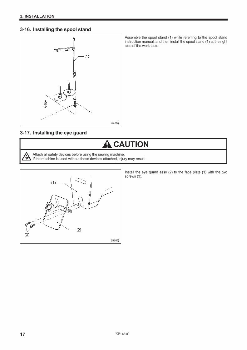
3-16. Installing the spool stand
Assemble the spool stand (1) while referring to the spool standinstruction manual, and then install the spool stand (1) at the rightside of the work table.
3-17. Installing the eye guard
CAUTIONAttach all safety devices before using the sewing machine.If the machine is used without these devices attached, injury may result.
Install the eye guard assy (2) to the face plate (1) with the twoscrews (3).
2509Q
2510Q

4. LUBRICATION
18KE-484C
4. LUBRICATION
CAUTIONTurn off the power switch before starting lubricating, otherwise the machine may operate if the foot switch is depressed bymistake, which could result in injury.
Be sure to wear protective goggles and gloves when handling the lubricating oil and grease, so that they do not get intoyour eyes or onto your skin, otherwise inflammation can result.Furthermore, do not drink the oil or eat the grease under any circumstances, as they can cause vomiting and diarrhoea.Keep the oil out of the reach of children.
Note 1: Fill the machine with oil when the oil level is down to about one-third full in the oil sight glass.If oil is not added and the oil drops below this level, there is the danger that the machine may seize during operation.
Note 2: Be sure to let the machine operate for a while after adding the oil.Note 3: If there is no more oil on the felt of the shuttle race base, problems with sewing may result, so add oil to the felt until it is
slightly soaked.Note 4: Use only specified Brother oil (Nisseki Mitsubishi Sewing Lube 10N;VG10) for the machine oil.
4-1. Lubrication points
1. Fill the arm-side oil tank with oil. 2. Fill the bed-side oil tank with oil
3. Add oil to the races (1) of the rotating hook and shuttlehook.* When setting up the sewing machine and when it hasn’t
been used for an extended period of time, be sure to add2-3 drops oil to the felt.
4. Fill the liquid cooling tank (2) with silicon oil (100 mm2/s).
3164Q 2513Q
2686Q2685Q
5. OPERATION
19 KE-484C
5. OPERATION
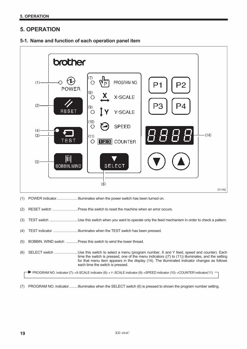
5-1. Name and function of each operation panel item
(1) POWER indicator......................Illuminates when the power switch has been turned on.
(2) RESET switch ..........................Press this switch to reset the machine when an error occurs.
(3) TEST switch .............................Use this switch when you want to operate only the feed mechanism in order to check a pattern.
(4) TEST indicator .........................Illuminates when the TEST switch has been pressed.
(5) BOBBIN. WIND switch ............Press this switch to wind the lower thread.
(6) SELECT switch ........................Use this switch to select a menu (program number, X and Y feed, speed and counter). Eachtime the switch is pressed, one of the menu indicators ((7) to (11)) illuminates, and the settingfor that menu item appears in the display (14). The illuminated indicator changes as followseach time the switch is pressed.
PROGRAM NO. indicator (7)�X-SCALE indicator (8)��-SCALE indicator (9)�SPEED indicator (10)�COUNTER indicator(11)
(7) PROGRAM NO. indicator.........Illuminates when the SELECT switch (6) is pressed to shown the program number setting.
2514Q

5. OPERATION
20KE-484C
(8) X-SCALE indicator....................Illuminates when the SELECT switch (6) is pressed to shown the X-scale setting.
(9) Y-SCALE indicator....................Illuminates when the SELECT switch (6) is pressed to shown the Y-scale setting.
(10) SPEED indicator .......................Illuminates when the SELECT switch (6) is pressed to shown the speed setting.
(11) COUNTER indicator .................Illuminates when the SELECT switch (6) is pressed to show the bobbin thread or productioncounter setting.
(12) DISPLAY SET switches............Used to change the menu details which are displayed in the window (14).
(13) User program switches.............Used to set and select user programs.
(14) Display window .........................This display window will indicate the current statu for the selected menu, error or memoryswitch.
2515Q

5. OPERATION
21 KE-484C
5-2. Operating procedure
PreparationTurn on the power switch.* The POWER indicator (1) will illuminate and the
program number will flash in the display window (14).
*1 For checking the origin points for X and Y feed*2 Custom-made program
Note when creating additional dataWhen sewing data with a small number of stitches (15 stitches or less) is sewn repeatedly (short cycle operation), theupper shaft motor may overheat and the “E-20” error code may be generated.
5-2-1. Setting the program number
1Press the SELECT switch (6)until the PROGRAM NO. in-dicator illuminates.
2Press the DISPLAY SETswitches (12) until the desiredprogram number is flashing inthe display window.
3Depress the work clamp switchto lower the work clamp, anddepress the start switch.
The display will stop flashing andilluminates steadily, and the feedmechanism will move to the sewing startposition.
This completes the setting of the programnumber.
5-2-2. Setting the X-scale and Y-scale
1Press the SELECT switch (6)until the X-scale or Y-scaleindicator illuminates.
2Press the DISPLAY SETswitches (12) until the desiredscale setting is flashing in thedisplay window.(The setting is displayed as a per-centage.)
3Depress the work clamp switchto lower the work clamp, anddepress the start switch.
The display will stop flashing andilluminates steadily, and the feedmechanism will move to the sewing startposition.
This completes the setting of the X-scale or Y-scale.
Note:* Be sure to check the sewing pattern (refer to page 24) after setting has been completed to make sure that the needle hole
does not go out of the area circumscribed by the work clamp.* The needle racking width for backtack stitches (with stitch widths of 1 mm or less) is not enlarged or reduced. If this results
in problems, set memo-0d to "ON" to enlarge or reduce the needle racking width for backtack stitches.
Factory default Variable rangeProgram No. 0*1 100- *2
X-scale (%) 100 20 - 200Y-scale (%) 100 20 - 200Speed (rpm) 2,000 1,000 - 2,200
2518Q 2519Q
3165Q
2516Q 2602Q
3165Q

5. OPERATION
22KE-484C
5-2-3. Setting the sewing speed
1Press the SELECT switch (6)until the SPEED indicator il-luminates.
2Press the DISPLAY SETswitches (12) until the desiredspeed setting is flashing in thedisplay window.
Note:Be sure to check the sewing pattern (refer to page 24) after setting has been completed to make sure that the needle hole does notgo out of the area circumscribed by the work clamp.
5-3. Operating the foot switch
When the work clamp switch (left side) is depressed to step 1,the work clamps on both sides are lowered.The work clamp lowering pattern can be set to a variety ofdifferent patterns. (Refer to “14. SETTING THE WORK CLAMPMODE”.When the start switch (right side) is depressed, sewing starts.
2520Q 3166Q
0330Q
Start switch
Work clamp switch
1st step2nd step

5. OPERATION
23 KE-484C
5-4. Operating the emergency stop switch
If the emergency stop switch is pressed while normal sewing or test sewing is being carried out, the sewing machine willimmediately stop operating.
Canceling an emergency stop1. Turn the emergency stop switch (1) clockwise and then
pull it out to release the lock.2. Press the RESET switch (2) on the control panel.
* The electronic alarm will stop sounding.3. If not joining a new thread, press the BOBBIN. WIND
switch (3) to trim the thread. Then, press the RESETswitch (2) once more so that the display panel flashes.Turn the pulley by hand to set the needle to the needle upstop position, and then continue with sewing.
Continuing sewing from a stopping pointIf the emergency stop switch was pressed because a threadbreakage occurred or the lower thread ran out, sewing canbe resumed from the point where the thread ended.1. Turn the emergency stop switch (1) clockwise and then
pull it out to release the lock.2. Press the RESET switch (2) on the control panel.
* The electronic alarm will stop sounding.3. Press the BOBBIN. WIND switch (3) to trim the thread.4. Press the BOBBIN. WIND switch (3) once more.
* The work clamp will move backward one stitch at atime while this switch is being pressed. If the workclamp moves back too far, press the TEST switch (4) tomove the work clamp forward. Press the TEST switch(4) once more when you would like the work clamp tostop.
5. Once the work clamp has returned to the desiredposition, depress the start switch. The sewing machinewill then resume sewing.
5-5. Operating the thread wiper switch
The thread wiper can be turned on and off using the threadwiper switch (1).
Note:When memory switch 2F (memo-2F) is ON, turn off thepower switch before operating the thread wiper switch.If you operate the thread wiper switch while the power is stillturned on, the work clamp may obstruct the thread wiper.
3167Q
2605Q
3169Q
2606Q
2607Q
3168Q
6. CHECKING THE SEWING PATTERN
24KE-484C
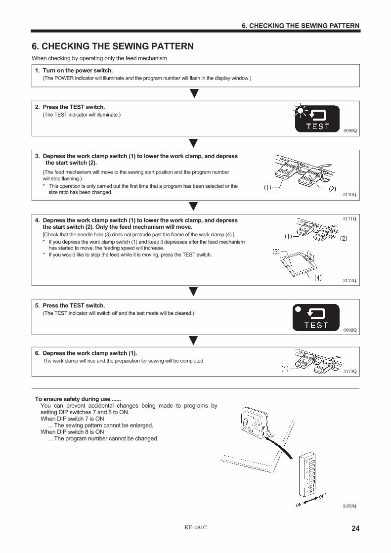
6. CHECKING THE SEWING PATTERN
When checking by operating only the feed mechanism
1. Turn on the power switch.
(The POWER indicator will illuminate and the program number will flash in the display window.)
2. Press the TEST switch.
(The TEST indicator will illuminate.)
3. Depress the work clamp switch (1) to lower the work clamp, and depress the start switch (2).
(The feed mechanism will move to the sewing start position and the program number
will stop flashing.)
* This operation is only carried out the first time that a program has been selected or thesize ratio has been changed.
4. Depress the work clamp switch (1) to lower the work clamp, and depressthe start switch (2). Only the feed mechanism will move.
[Check that the needle hole (3) does not protrude past the frame of the work clamp (4).]
* If you depress the work clamp switch (1) and keep it depresses after the feed mechanismhas started to move, the feeding speed will increase.
* If you would like to stop the feed while it is moving, press the TEST switch.
5. Press the TEST switch.
(The TEST indicator will switch off and the test mode will be cleared.)
6. Depress the work clamp switch (1).
The work clamp will rise and the preparation for sewing will be completed.
To ensure safety during use ......You can prevent accidental changes being made to programs bysetting DIP switches 7 and 8 to ON.When DIP switch 7 is ON
... The sewing pattern cannot be enlarged.When DIP switch 8 is ON
... The program number cannot be changed.
3173Q
0092Q
2459Q
3172Q
3171Q
0090Q
3170Q

7. CORRECT USE
25 KE-484C
7. CORRECT USE
7-1. Installing the needle
CAUTIONTurn off the power switch before installing the needle, otherwise the machine may operate if the foot switch is depressed bymistake , which could result in injury.
Loosen the set screw (1), insert the needle (2) as far as it will goso that the groove is facing toward you, and then tighten the setscrew (1).
7-2. Threading the upper thread
CAUTIONTurn off the power switch before threading the thread, otherwise the machine may operate if the foot switch is depressedby mistake, which could result in injury.
Thread the upper thread correctly as shown in the illustration below.
3176Q
Approx. 40mm
3175Q
3174Q

7. CORRECT USE
26KE-484C
7-3. Winding the lower thread
CAUTIONDo not touch any of the moving parts or press any objects against the machine while winding the lower thread, as this mayresult in personal injury or damage to the machine.
1. Place the bobbin all the way onto the shaft.
2. Thread the thread as shown in the illustration atright, wind the thread around the bobbin severaltimes in the direction of the arrow, and then pressthe bobbin presser (1).
3. Turn on the power switch.(The POWER indicator on the operation panel will illuminate.)
4. Depress the foot switch (2) to move the feed mechanism to thesewing start and raise the work clamp.
Depress the work clamp switch (3) to lower the work clamp.
5. Check that the needle is not touching the work clamp, and then while pressing theBOBBIN. WIND switch (4), depress the start switch (2) to start the machine. Keepdepressing the start switch (2) until the lower thread stops being wound onto thebobbin.
Release the BOBBIN. WIND switch (4) after the machine starts operating. If you release the startswitch before winding is completed, depress it once more while pressing and holding the BOBBIN.WIND switch (4).
6. The bobbin presser (1) will automatically return to its original position after a set amount of thread (80 - 90% of thebobbin capacity) has been wound on.
7. Release the start switch (2).
<<If the thread winds onto the bobbin unevenly>>If the thread winds onto the bobbin unevenly, loosenthe nut (7) and turn the bobbin winder thread tensionstud (8) to adjust.* If the thread winds on as shown in A, turn the bobbin
winder thread tension stud (8) clockwise; if it winds on asshown in B, turn the bobbin winder thread tension stud (8)counterclockwise.
8. Remove the bobbin,hook the thread ontothe knife (5), and thenpull the bobbin in thedirection of the arrow tocut the thread.
9. To wind more threadonto the bobbin, loosenthe set screw (6) andpull the bobbin presser(1) outward.
3179Q
3180Q
3181Q
Case A
Case B
3178Q
2527Q
3177Q

7. CORRECT USE
27 KE-484C
7-4. Replacing the bobbin case and threading the thread
CAUTION
Turn off the power switch before removing or inserting the bobbin case, otherwise the machine may operate if the foot switch is depressed by mistake, which could result in injury.
1. Pull the shuttle race cover (1) toward you to open it. 2. Insert a new bobbin into the bobbin case, and then pass the thread through the slot (2) and the spring. Pull it out approximately
30 mm. Check that the bobbin turns in the direction of the arrow when the thread is pulled at this time.
7-5. Thread tension
7-5-1. Reference thread tension
Upper thread #4 or equivalent
Lower thread #4 or equivalent
Upper thread tension (N) 4.5 - 5.0
Lower thread tension (N) 1.0 - 1.2
Thread take-up spring height (mm) 0 - 5
Thread take-up spring tension (N) 2.0 - 2.5
Pre-tension (N) 0.3 - 0.5
3228Q
3229Q
3230Q
Pull

7. CORRECT USE
28KE-484C
7-5-2. Lower thread tension
Turn the thread tension nut (1) to adjust the lower thread tensionto between 1.0 - 1.2 N.
7-5-3. Upper thread tension
Turn the tension nut (1) (main tension) to adjust the tension asappropriate for the material being sewn.Furthermore, turn the thread nut (2) (sub-tension) to adjust theremaining length of upper thread to 35 - 40 mm, when the threadtake-up lever is not used.
7-5-4. Thread take-up spring height
Loosen the set screw (1) and turn the tensioner body to adjustthe thread take-up spring height.
3186Q
Weaker
Stronger
Weaker Stronger
3185Q
1.0 - 1.2 N
Weaker Stronger
3187Q
Lower Higher

7. CORRECT USE
29 KE-484C
7-5-5. Thread take-up spring tension
Turn the tension stud (1) with a screwdriver.
7-5-6. Adjusting arm thread guide R
The standard position of arm thread guide R (1) is the posi-tion where the screw (2) is in the center of the adjustablerange for arm thread guide R (1).To adjust the position, loosen the screw (2) and then movearm thread guide R (1).* When sewing thick material, move arm thread guide R (1)
to the left. (The thread take-up amount will becomegreater.)
* When sewing thin material, move arm thread guide R (1)to the right. (The thread take-up amount will becomeless.)
7-5-7. Thread take-up amount
Loosen the nut (1) and move the stopper (bolt) (2) to adjustthe protruding position of the cylinder (3).* To reduce the thread take-up amount, tighten the stopper
(2).* To increase the thread take-up amount, loosen the
stopper (2).
Become greater Become less
3189Q
3188Q
WeakerStronger
3190Q
8. SEWING
30KE-484C
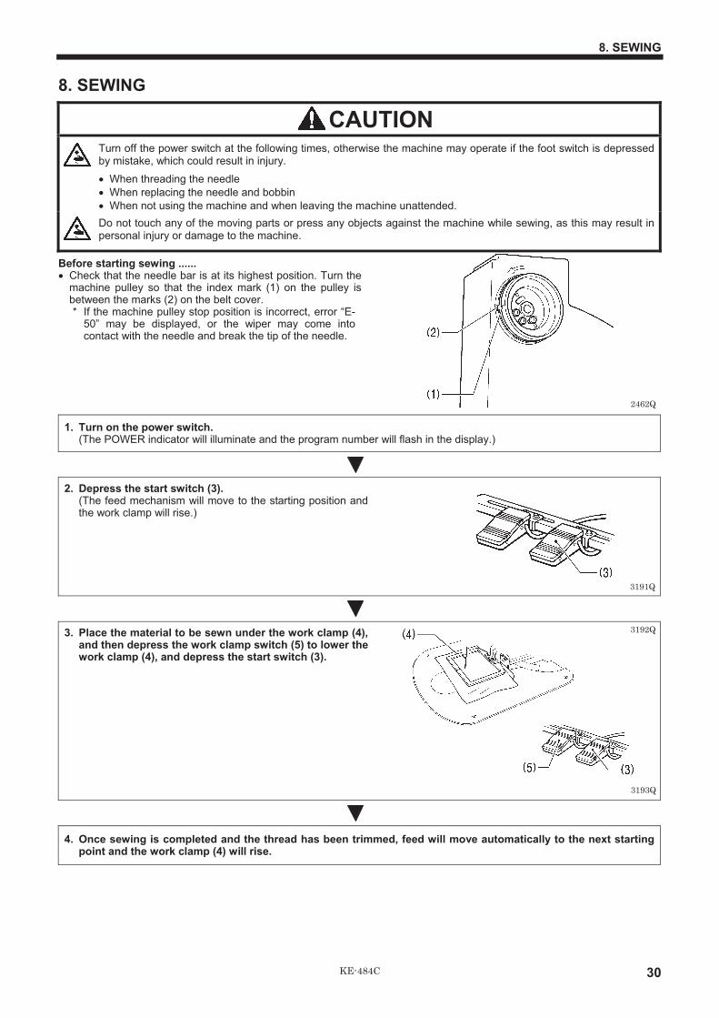
8. SEWING
CAUTIONTurn off the power switch at the following times, otherwise the machine may operate if the foot switch is depressedby mistake, which could result in injury.
� When threading the needle
� When replacing the needle and bobbin
� When not using the machine and when leaving the machine unattended.
Do not touch any of the moving parts or press any objects against the machine while sewing, as this may result inpersonal injury or damage to the machine.
Before starting sewing ......� Check that the needle bar is at its highest position. Turn the
machine pulley so that the index mark (1) on the pulley isbetween the marks (2) on the belt cover.* If the machine pulley stop position is incorrect, error “E-
50” may be displayed, or the wiper may come intocontact with the needle and break the tip of the needle.
1. Turn on the power switch.(The POWER indicator will illuminate and the program number will flash in the display.)
2. Depress the start switch (3).(The feed mechanism will move to the starting position andthe work clamp will rise.)
3. Place the material to be sewn under the work clamp (4),and then depress the work clamp switch (5) to lower thework clamp (4), and depress the start switch (3).
4. Once sewing is completed and the thread has been trimmed, feed will move automatically to the next startingpoint and the work clamp (4) will rise.
2462Q
3191Q
3193Q
3192Q

9. MAINTENANCE AND INSPECTION
31 KE-484C
9. MAINTENANCE AND INSPECTION
CAUTIONTurn off the power switch before carrying out cleaning, otherwise the machine may operate if the foot switch ispressed by mistake, which could result in injury.
Be sure to wear protective goggles and gloves when handling the lubricating oil and grease, so that they do not getinto your eyes or onto your skin, otherwise inflammation can result.Furthermore, do not drink the oil or eat the grease under any circumstances, as they can cause vomiting anddiarrhoea. Keep the oil out of the reach of children.
Wait until the motor has cooled down before cleaning the air holes.The motor may be hot immediately after it has been used, and it may cause burns if touched.
9-1. Checking the needle
Always check that the tip of the needle is not broken andalso the needle is not bent before starting sewing.
9-2. Cleaning the rotary hook
1. Pull the shuttle race cover toward you to open it, and thenremove the bobbin case.
2. Clean all the dust and thread ends from the shuttle race.
0121Q
3194Q
3195Q

9. MAINTENANCE AND INSPECTION
32KE-484C
9-3. Lubrication
Note1: Fill the machine with oil when the oil level is down to about one-third full in the oil sight glass. If oil is not added andthe oil drops below this level, there is the danger that the machine may seize during operation.
Note2: Be sure to let the machine operate for a while after adding the oil.Note3: If there is no more oil on the felt of the shuttle race base, problems with sewing may result, so add oil to the felt until it
is slightly soaked.Note4: Use only specified Brother oil (Nisseki Mitsubishi Sewing Lube 10N;VG10) for the machine oil.
1. Fill the arm-side oil tank with oil.
2. Fill the bed-side oil tank with oil.
3. Add oil to the races (1) of the rotating hook and shuttlehook.* When setting up the sewing machine and when it
hasn’t been used for an extended period of time, besure to add 2-3 drops oil to the felt.
4. Fill the liquid cooling tank (2) with silicon oil (100 mm2/s).
2513Q
3164Q
2685Q
2686Q

9. MAINTENANCE AND INSPECTION
33 KE-484C
9-4. Draining the oil
1. Remove and empty the waste oil container (1) wheneverit is full.
2. After emptying the waste oil container (1), screw it backinto its original position.
9-5. Cleaning the control box air inlet port
Use a vacuum cleaner to clean the filter in the air inlet port(2) of the control box (1) at least once a month.
* If the machine is used while the air inlet port is blocked,the inside of the control box will overheat.When this happens, the overheating error code “E-d0” willbe displayed and you will not be able to operate thesewing machine.
9-6. Cleaning the air holes of belt cover and frame side cover
Remove the belt cover (1) and the frame side cover (2), andthen clean the air holes (3).After cleaning, install the belt cover (1) and the frame sidecover (2).* If dust collects in the air holes, it may cause the motor to
overheat. The air holes should be cleaned at regularintervals.In addition, be careful not to let any foreign matter get intothe air holes.
9-7. Cleaning the eye guard
� �Wipe the eye guard clean with a soft cloth.Note:
Do not use solvents such as kerosene or thinner to cleanthe eye guard.
2550Q
2551Q
0128Q
2463Q

10. STANDARD ADJUSTMENTS
34KE-484C
10. STANDARD ADJUSTMENTS
CAUTIONMaintenance and inspection of the sewing machineshould only be carried out by a qualified technician.
Ask your Brother dealer or a qualified electrician tocarry out any maintenance and inspection of theelectrical system.
Turn off the power switch and disconnect the powercord from the wall outlet at the following times,otherwise the machine may operate if the foot switchis depressed by mistake, which could result in injury.
� When carrying out inspection, adjustment andmaintenance
� When replacing consumable parts such as therotary hook and knife
Hold the machine head with both hands when tilting itback or returning it to its original position.Furthermore, after tilting back the machine head, donot push the face plate side or the pulley side fromabove, as this could cause the machine head totopple over, which may result in personal injury ordamage to the machine.
If the power switch and air need to be left on whencarrying out some adjustment, be extremely carefulto observe all safety precautions.
If any safety devices have been removed, beabsolutely sure to re-install them to their originalpositions and check that they operate correctlybefore using the machine.
10-1. Adjusting the needle bar height
Turn the machine pulley to move the needle bar to the lowest position. Then remove the rubber plug (2), loosen the set screw(3) and then move the needle bar up or down to adjust so that the second reference line from the bottom of the needle(reference line A) is aligned with the lower edge of the needle bar bush (1).
10-2. Adjusting the needle bar lift amount
Turn the machine pulley to raise the needle bar from the lowest position until the lowest reference line on the needle(reference line B) is aligned with the lower edge of the needle bar bush (1). Then loosen the set screw (2) and move the rotaryhook to adjust so that the tip of the rotary hook is aligned with the needle center line.
3196Q 3197Q
3198Q 3200Q 3199Q

10. STANDARD ADJUSTMENTS
35 KE-484C
10-3. Adjusting the needle clearance
Turn the machine pulley to align the tip of the rotary hook (1)with the needle center line. Then loosen the set screw (2) toadjust so that the clearance between the needle and therotary hook (1) is 0.01 - 0.08 mm.
10-4. Adjusting the thread take-up amount
At the time of shipment from the factory, the thread take-up amount (stroke) of the thread take-up lever (1) is set to thestandard setting of 7 mm. You may need to adjust this setting depending on the sewing conditions to prevent the thread frompulling out at the sewing start.[Adjustment method]Loosen the nut (2) and move the stopper (bolt) (3) to adjust the protruding position of the cylinder (4).* To reduce the thread take-up amount, tighten the stopper (3).* To increase the thread take-up amount, loosen the stopper (3).Note:
If the stroke of the thread take-up lever (1) is shorter than necessary, the needle thread trailing length may become tooshort and the thread may come out of the needle. Furthermore, if it is larger than necessary, the needle thread trailinglength may become too long and the underside of the article being sewn may become untidy.
3201Q
Thread take-up amount (stroke)
3203Q 3202Q

10. STANDARD ADJUSTMENTS
36KE-484C
10-5. Adjusting the movable knife
Loosen the nut (2) and move the connecting rod lever (3) to the left or right to adjust so that the V section A is aligned with theindex mark B on the needle plate when the sewing machine in the stopped position and the movable knife (1) is pushed to themachine pulley side so that there is no play.
3206Q 3207Q

10. STANDARD ADJUSTMENTS
37 KE-484C
10-5-1. Replacing the movable knife and fixed knife
1. Open the large shuttle hook cover, remove the bolts (1) and the feed plate (2).2. Remove the two screws (3) and the two screws (4), and then remove the needle plate (5).3. Remove the two screws (6) and the feed bar guide plate FF (7).4. Remove the thread trimmer connecting rod (8) from the connecting rod lever pin (9).
5. Remove the movable knife (10) and replace it with a new one. At this time, check that the movable knife (10) and the fixedknife (11) cut the thread cleanly. If necessary, adjust by using the apropriate movable knife washer (12) (supplied asaccessories).* Apply grease to the outside of the collar (13) at this time.
6. Install the fixed knife (11) at a distance of 0.5 mm from the needle hole plate (14).7. Place the thread trimming connecting rod (8) onto the connecting rod lever pin (9), and then install to the needle plate(5).
2615Q 3208Q
3209Q 3210Q

10. STANDARD ADJUSTMENTS
38KE-484C
10-5-2. Adjusting the engagement of the movable knife and fixed knife
A. After the movable knife and fixed knife are properly engaged, tighten the screw as shown in Fig. 1.B. Turn the movable knife (in the direction of the arrow) while the screw is still tightened.C. Loosen the screw.D. Turn the movable knife (in the direction of the arrow) while the screw is still loosened.Repeat above steps A , B, C and D four or five times to maintain the cutting performance of the knife.
10-6. Adjusting the work clamp lift amount
The maximum work clamp lift amount is 25 mm from the top of the needle plate.The lift amount is adjusted 17 mm at the time of shipment.
1. Raise the work clamp (1) and loosen the screws (2).2. Adjust the work clamp lift by moving the presser levers (3) and (4) up and down and then tighten the screws (2).
* If movement is sluggish when the work clamp (1) is being raised and lowered, it may not be possible to increase thework clamp (1) lift amount.Apply grease to the sliding part of the work clamp (1) (grease is already applied at the time of shipment), and check thatthe movement becomes easier.
0149QFig. 1
Movable knife
Fixed knife
3213Q
Cutting
edge
Cutting
edge
3211Q
Cutting edge
Cuttingedge
2618Q
25 mm max.

10. STANDARD ADJUSTMENTS
39 KE-484C
10-7. Work clamp interchangeability
The BAS-311F work clamp can also be used with the KE-484C.Replace the feed bar guide cover (1) with the feed bar guidecover assembly, LL (2) (optional).Then, change the installation position for the presser armassembly (3) from the standard installation position A toinstallation position B.
To use the BAS-311F work clamp and the KE-484C workclamp interchangeablyUse the optional work clamp 434EMK2 air (5) with the KE-484C work clamp.It can then be used interchangeably with the BAS- 311F workclamp (6) at installation position B.
10-8. Adjusting the needle up stop position
The needle up stop position is adjusted so that the indexmark (2) on the machine pulley (1) is inside the mark (4) onthe belt cover (3).If adjustment is necessary, loosen the screw (5) at the “U”mark of the machine pulley (1) and adjust the position of themachine pulley (1). The machine pulley (1) stops later if it isturned clockwise, and it stops earlier if it is turned counter-clockwise.Note:
The screw (6) at the “D” mark is an adjusting screw for theneedle down detection function and is adjusted to matchthe feed timing, so it should not be loosened.The screw (7) is a screw for detecting the machine stopposition, and should not be loosened.
* If the index mark (2) is not inside the mark (4) when thesewing machine is started, error code “E-50” will bedisplayed. Turn the machine pulley to move the index mark(2) to the correct position and then start the sewingmachine.
2619Q
2620Q
2576Q

10. STANDARD ADJUSTMENTS
40KE-484C
10-9. Adjusting the thread wiper
1. Loosen the set screw (2) and move the wiper arm support (3) up or down to adjust so that the clearance between the topof the thread wiper and the needle point (1) is 2 � 0.5 mm when the thread wiper is aligned with the center of the needle.* Before carrying out this adjustment, check that the needle bar is lowered 3.5 to 4.0 mm from the needle up stop position
when the sewing machine stops.2. Loosen the two bolts (4) and move the wiper solenoid cover (5) up or down so that the thread wiper is approximately 38
mm from the needle when it is at the standby position.
10-10. Adjustment of air pressure
1. Air pressure should be 0.5 Mpa.The air pressure can be adjusted by pulling up and turningthe control knob (2) on the integrator (1).After adjustment is complete, push the control knob (2)downward to lock it.
2. If water stands in the bottle of the integrator (1), turn thedrain cock (3) in the direction indicated by an arrow todrain the water.
3214Q 3216Q
Approx.38 mm
3215Q 3217Q
3218Q
Increase pressure
10. STANDARD ADJUSTMENTS
41 KE-484C
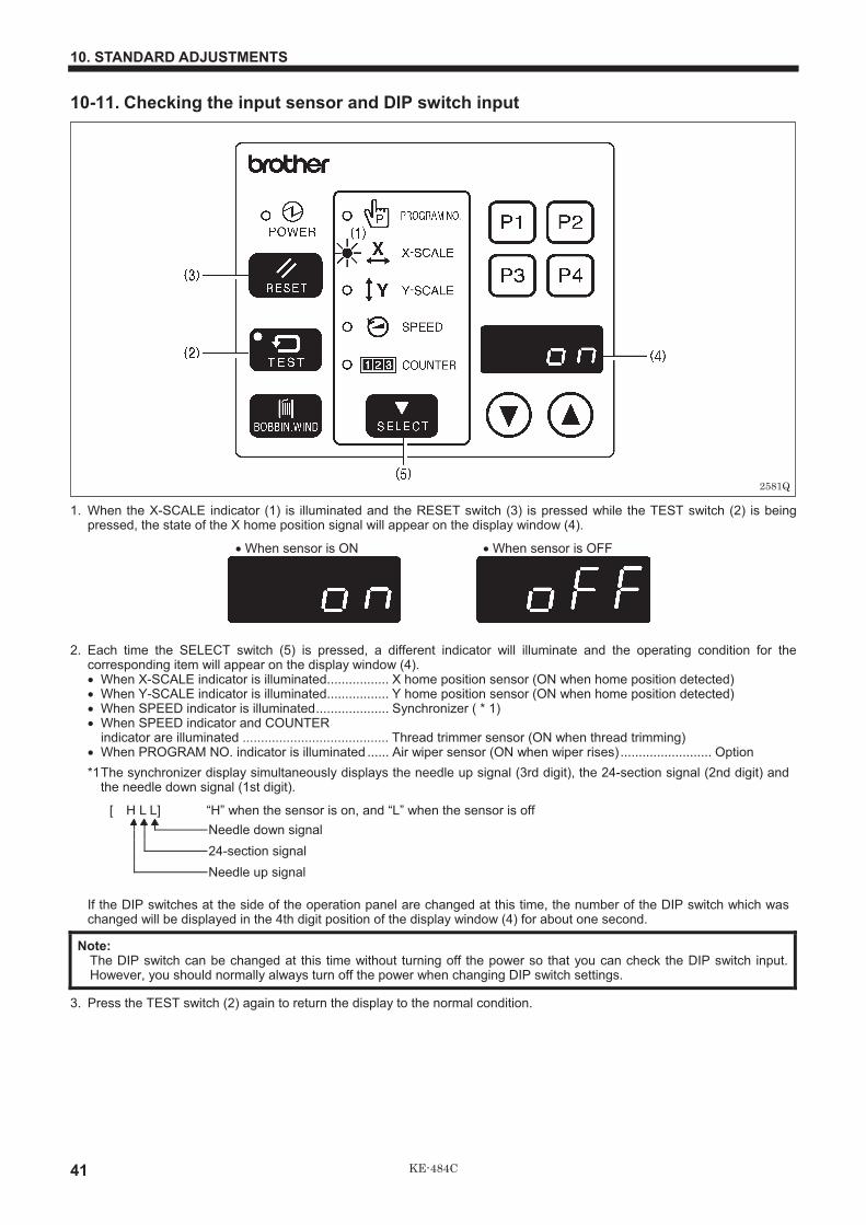
10-11. Checking the input sensor and DIP switch input
1. When the X-SCALE indicator (1) is illuminated and the RESET switch (3) is pressed while the TEST switch (2) is beingpressed, the state of the X home position signal will appear on the display window (4).
� When sensor is ON � When sensor is OFF
2. Each time the SELECT switch (5) is pressed, a different indicator will illuminate and the operating condition for thecorresponding item will appear on the display window (4).� When X-SCALE indicator is illuminated................. X home position sensor (ON when home position detected)� When Y-SCALE indicator is illuminated................. Y home position sensor (ON when home position detected)� When SPEED indicator is illuminated.................... Synchronizer ( * 1)� When SPEED indicator and COUNTER
indicator are illuminated ........................................ Thread trimmer sensor (ON when thread trimming)� When PROGRAM NO. indicator is illuminated ...... Air wiper sensor (ON when wiper rises) ......................... Option
*1The synchronizer display simultaneously displays the needle up signal (3rd digit), the 24-section signal (2nd digit) andthe needle down signal (1st digit).
[ H L L] “H” when the sensor is on, and “L” when the sensor is off
Needle down signal
24-section signal
Needle up signal
If the DIP switches at the side of the operation panel are changed at this time, the number of the DIP switch which waschanged will be displayed in the 4th digit position of the display window (4) for about one second.
Note:The DIP switch can be changed at this time without turning off the power so that you can check the DIP switch input.However, you should normally always turn off the power when changing DIP switch settings.
3. Press the TEST switch (2) again to return the display to the normal condition.
2581Q
10. STANDARD ADJUSTMENTS
42KE-484C
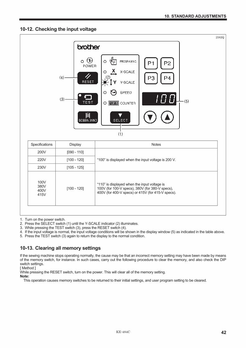
10-12. Checking the input voltage
1. Turn on the power switch.2. Press the SELECT switch (1) until the Y-SCALE indicator (2) illuminates.3. While pressing the TEST switch (3), press the RESET switch (4).4. If the input voltage is normal, the input voltage conditions will be shown in the display window (5) as indicated in the table above.5. Press the TEST switch (3) again to return the display to the normal condition.
10-13. Clearing all memory settings
If the sewing machine stops operating normally, the cause may be that an incorrect memory setting may have been made by meansof the memory switch, for instance. In such cases, carry out the following procedure to clear the memory, and also check the DIPswitch settings.[ Method ]While pressing the RESET switch, turn on the power. This will clear all of the memory setting.Note:
This operation causes memory switches to be returned to their initial settings, and user program setting to be cleared.
Specifications Display Notes
200V [090 - 110]
220V [100 - 120]
230V [105 - 125]
“100” is displayed when the input voltage is 200 V.
100V380V400V415V
[100 - 120]“110” is displayed when the input voltage is100V (for 100-V specs), 380V (for 380-V specs),400V (for 400-V specs) or 415V (for 415-V specs).
2582Q

10. STANDARD ADJUSTMENTS
43 KE-484C
10-14. Moving stitch patterns
� Programs which have already been programmed can be moved up, down and to the left and right.* Once the power switch has been turned off, the amount of movement that has been stored in memory is reset. However, if
memory switch memo-28 is set to ON, you can keep the amount of movement recorded in memory. (The amount of movementis retained in memory even when the power switch is turned off.)
* The amount of movement is reset when you change the program number.� The feed position can be set to the any position desired.
1. Select the program number, and then press the start switch once to move the feed mechanism to the sewing start position.2. Press the SELECT switch (1) until the PROGRAM NO. indicator (2) illuminates.3. While pressing the TEST switch (3), press the RESET switch (4).
* The TEST indicator (5) will illuminate and < > will appear in the display window (6).4. Press the SELECT switch (1) so that either the X-SCALE indicator (7) or Y-SCALE indicator (8) illuminates.5. Press the DISPLAY SET switches (9) to move the feed mechanism one pulse at a time.
� If the DISPLAY SET ( ) switch is pressed while the X-SCALE indicator is illuminated, the feed mechanism will move to theleft.
� If the DISPLAY SET ( ) switch is pressed while the X-SCALE indicator is illuminated, the feed mechanism will move to theright.
� If the DISPLAY SET ( ) switch is pressed while the Y-SCALE indicator is illuminated, the feed mechanism will move down.� If the DISPLAY SET ( ) switch is pressed while the Y-SCALE indicator is illuminated, the feed mechanism will move up.
6. When the TEST switch (3) is pressed after the above fine adjustments have been made, the TEST indicator (5) and displaywindow (6) will both switch off and movement of the stitch pattern will be completed.Note:
When moving the stitch pattern, take the whole of the pattern area into consideration so that no parts extend outside the sewingarea when the pattern is sewn.
* If you would like to set the feed position to a desired position, carry out steps 2. to 6. above while the display window (6) isflashing. The stitch pattern will not be moved at this time.
2583Q

11. USING THE COUNTERS
44KE-484C
11. USING THE COUNTERS
11-1. Using the bobbin thread counterIf you use the bobbin thread counter to set the number of articles which can be sewn with the amount of bobbin threadavailable, you can stop the bobbin thread running out in the middle of sewing a pattern.
1. Press the SELECT switch (1) until the COUNTERindicator (2) illuminates.
2. While pressing the TEST switch (3), press the RESETswitch (4).* The COUNTER indicator (2) will flash and the counter
will switch to bobbin thread counter setting mode.3. Press the DISPLAY SET switches (5) to set the number of
articles to be sewn.� The bobbin thread counter can be set to sew a number
of articles from one (“0001”) through to 9999 (“9999”).If the bobbin thread counter is set to “0000”, sewing iscarried out without the number of articles sewn beingcounted.
� If you press the RESET switch (4) while setting thebobbin thread counter, the setting will return to “0000”.
4. Press the TEST switch (3).* The number displayed in the display window (6) will
then be stored as the bobbin thread counter setting.
5. Each time the sewing of a single article is completed, the number being displayed in the display window (6) will becomesmaller. When the number of articles set by the bobbin thread counter have all been sewn, “0000” will be displayed in thedisplay window (6), and an alarm will start sounding continuously.* The sewing machine will not operate during this time, even if the foot switch is depressed.
6. Replace the bobbin, and then press the RESET switch (4).* The alarm will then stop sounding, and the number which was set in step 3. above will be re-displayed in the display
window (6).
11-2. Using the production counterThe production counter can be displayed in the display window (6) separately from the bobbin thread counter.
1. Press the SELECT switch (1) until the SPEED indicator(2) illuminates.
2. While pressing the TEST switch (3), press the RESETswitch (4).* The COUNTER indicator (5) and the SPEED indicator
(2) will illuminate, and the production counter will bedisplayed in the display window (6).
� Press the RESET switch (4) to reset the productioncounter to “0000”.
� You can also press the DISPLAY SET switches (7) toset the production counter to the desired value.
3. When the foot switch is depressed, the sewing machinewill start sewing.
4. If you press the TEST switch (3) or the SELECT switch (1),the display will return to showing the bobbin threadcounter.
11. USING THE COUNTERS2585Q
2584Q
12. CHANGING FUNCTIONS USING THE DIP SWITCHES
45 KE-484C
12. CHANGING FUNCTIONS USING THE DIP SWITCHES
12-1. Operation panel DIP switches
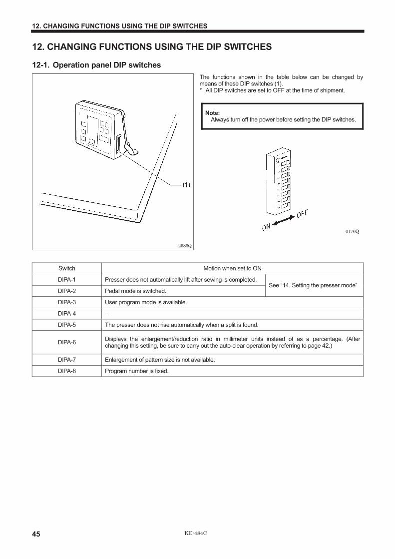
The functions shown in the table below can be changed bymeans of these DIP switches (1).* All DIP switches are set to OFF at the time of shipment.
Note:Always turn off the power before setting the DIP switches.
Switch Motion when set to ON
DIPA-1 Presser does not automatically lift after sewing is completed.
DIPA-2 Pedal mode is switched.See “14. Setting the presser mode”
DIPA-3 User program mode is available.
DIPA-4
DIPA-5 The presser does not rise automatically when a split is found.
DIPA-6Displays the enlargement/reduction ratio in millimeter units instead of as a percentage. (Afterchanging this setting, be sure to carry out the auto-clear operation by referring to page 42.)
DIPA-7 Enlargement of pattern size is not available.
DIPA-8 Program number is fixed.
0176Q
2586Q
12. CHANGING FUNCTIONS USING THE DIP SWITCHES
46KE-484C
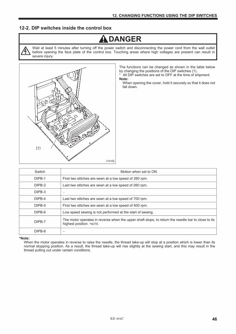
12-2. DIP switches inside the control box
DANGERWait at least 5 minutes after turning off the power switch and disconnecting the power cord from the wall outletbefore opening the face plate of the control box. Touching areas where high voltages are present can result insevere injury.
The functions can be changed as shown in the table belowby changing the positions of the DIP switches (1).* All DIP switches are set to OFF at the time of shipment.Note:
When opening the cover, hold it securely so that it does notfall down.
Switch Motion when set to ON
DIPB-1 First two stitches are sewn at a low speed of 260 rpm.
DIPB-2 Last two stitches are sewn at a low speed of 260 rpm.
DIPB-3
DIPB-4 Last two stitches are sewn at a low speed of 700 rpm.
DIPB-5 First two stitches are sewn at a low speed of 400 rpm.
DIPB-6 Low speed sewing is not performed at the start of sewing.
DIPB-7The motor operates in reverse when the upper shaft stops, to return the needle bar to close to itshighest position. *NOTE
DIPB-8
*Note:When the motor operates in reverse to raise the needle, the thread take-up will stop at a position which is lower than itsnormal stopping position. As a result, the thread take-up will rise slightly at the sewing start, and this may result in thethread pulling out under certain conditions.
2484Q

12. CHANGING FUNCTIONS USING THE DIP SWITCHES
47 KE-484C
12-3. Using user programs
Recording a user program
1. Turn off the power switch and then set DIP switch A-3of the DIP switches (1) to ON.
2. Turn on the power switch.While pressing the TEST switch (2), press the SELECTswitch (3).
* All of the menu indicators ((4) to (8)) will illuminate and the modewill switch to recording mode.
* In addition, “PP 1” will appear in the display window (9) toindicate that user program No.1 is being recorded. (Oncerecording of No.1 is completed, No.2 will be displayed; onceNo.2 is completed, No.3 will be displayed. Thus the nextunrecorded program letter is always displayed.)
3. Press the SELECT switch (3).
* The PROGRAM NO. indicator (4) will illuminate.
4. Press the DISPLAY SET switches (10) to select the number for the program that you would like to record.
5. Press the SELECT switch (3). * The X-SCALE indicator (5) will illuminate.
6. Press the DISPLAY SET swithes (10) to select the X scale setting that you would like to record.
7. Press the SELECT switch (3). * The Y-SCALE indicator (6) will illuminate.
8. Press the DISPLAY SET switches (10) to select the Y scale setting that you would like to record.
9. Press the SELECT switch (3). * The SPEED indicator (7) will illuminate.
10. Press the DISPLAY SET switches (10) to select the speed setting that you would like to record.
11. Press the SELECT switch (3). * This completes the recording of user program No.1.
* “PP 2” will then appear in the display window (9), to indicate that user program No.2 is now being recorded.Repeat steps 3. through to 11. to record further programs as desired.
12. Press the TEST switch (2). This completes the recording.
* The menu indicators ((4) to (8)) will all illuminate and “P1” will appear in the display to indicate that user program No.1 is currentlyselected.
It can store sixteen different programs which can include details such as the program number, X scale, Y scale and sewingspeed. If you are sewing certain patterns over and over again, it is useful to record the settings for these patterns into a userprogram.
User program...
2589Q
2588Q

12. CHANGING FUNCTIONS USING THE DIP SWITCHES
48KE-484C
Using a user program
1. Press the DISPLAY SET switches (10) to select the speed program number for the user program that you wouldlike to use.* The user program except P16 can also be selected using the user program switches (11). (See below.)
2. Depress the work clamp switch to lower the work clamp, and depress the start switch.
3. Check the sewing pattern (see P.24), and then sew the pattern selected.
* P1 to P4 can be selected using the P1 to P4 user program switches (11). P5 to P15 can be selected by pressing the P1 toP4 switches together in various combinations as shown below.
The switches with solid lines are valid switches for selection.
Clearing the user programs
1. Switch the machine to recording mode by the procedure in steps 2. of recording a user program.
2. Use the DISPLAY SET switches (10) to specify the user program number which is to be cleared of data.
3. Press the RESET switch (12).* The buzzer will sound and the user program with the number selected will be cleared.* If you press and hold the RESET switch (12) until after the buzzer has sounded twice, all user programs will be cleared.
Note:If data has been recorded in user programs P1, P2, P3 and P4 and you then clear the data in user program P2, thecontents of P3 will be transferred to P2, and the contents of P4 will be transferred to P3.
0472Q
To select P5 To select P10To select P9To select P8To select P7To select P6
To select P15To select P14To select P13To select P12To select P11

13. CHANGING SPECIAL FUNCTIONS USING THE MEMORY SWITCHES
49 KE-484C
13. CHANGING SPECIAL FUNCTIONS USING THE MEMORY SWITCHES
The functions of the switches on the operation panel (1) can be changed to carry out special functions.Note:
After changing the memory switch settings, press the power switch to turn the power off and then back on again.1. Turn on the power switch.2. While pressing the TEST switch (2), press the BOBBIN.
WIND switch (3).* “00 - - ” will appear in the display window (4).
3. Press the DISPLAY SET switches (5) to set the twodigits at the left of the display window (4) to thecorresponding number (00 to 4F) of the function shownin the table below that you would like to select.
4. When the BOBBIN. WIND switch (3) is pressed, thetwo spaces at the right in the display window willchange from “ - - ” to “ON”.* If you press the RESET switch (6) at this time,
memory switches will be returned to their initialsettings (factory default settings).
5. Press the TEST switch (2).* The display will return to normal.
<Memory switches 00 - 0F>
Switch Motion when set to ON Initial value
memo-00At the end of sewing, the feed plate will be returned to the sewing start point viamechanical home position.
--
memo-01 Work clamp will move to the sewing start point, and then will be lifted. ON
memo-02Feed will move automatically to the next starting point at the same time as a user programis switched.(Normally it moves to the starting point after sewing starts.)
--
memo-03When sewing using programs, the programs which have been set will be sewn innumerical order. (Cycle sewing mode is set.)
--
memo-04The sewing speed will be fixed at the minimum speed for the maximum pitch of the sewingdata. (Set this to ON if you are concerned that variations in pitch may cause changes inthe sewing speed.)
--
memo-05Increases the presser solenoid lifting force (Set to ON when using the optional spring forextra-heavy material)
--
memo-06 Enlargement and reduction ratio settings for X and Y become the same. --
memo-07 --
memo-08 Test feeding is carried out stitch by stitch when the foot switch is depressed. --
memo-09The sewing start point becomes the reference point for enlargements andreductions. (The reference point for enlargements and reductions isnormally the center of the sewing frame.)
--
memo-0A --
memo-0b --
memo-0c Needle stops in up position during emergency stop. --
memo-0dThe bar tacking stitches (with a pitch of less than 1 mm) are also enlarged and reduced.(Normally stitches with a pitch of less than 1 mm are not enlarged or reduced.)
--
memo-0ETest feeding will be performed at the same speed as that for actual sewing. (This is usedfor checking feeding operation.)
--
memo-0FAfter sewing is finished, the work clamp automatically opens and closes once (practiceoperation).
--
-- : OFF
2590Q
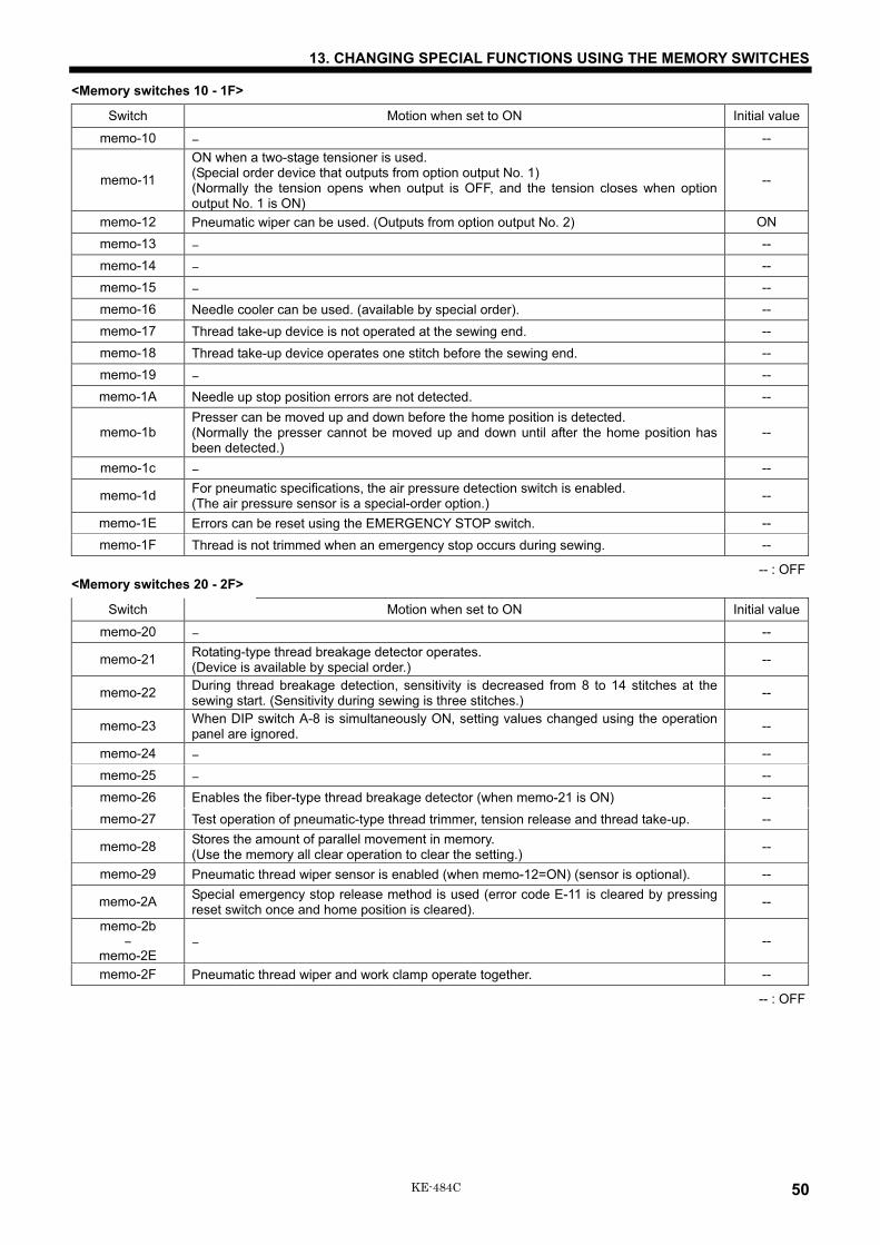
13. CHANGING SPECIAL FUNCTIONS USING THE MEMORY SWITCHES
50 KE-484C
<Memory switches 10 - 1F>
Switch Motion when set to ON Initial value
memo-10 � --
memo-11
ON when a two-stage tensioner is used. (Special order device that outputs from option output No. 1) (Normally the tension opens when output is OFF, and the tension closes when option output No. 1 is ON)
--
memo-12 Pneumatic wiper can be used. (Outputs from option output No. 2) ON
memo-13 � --
memo-14 � --
memo-15 � --
memo-16 Needle cooler can be used. (available by special order). --
memo-17 Thread take-up device is not operated at the sewing end. --
memo-18 Thread take-up device operates one stitch before the sewing end. --
memo-19 � --
memo-1A Needle up stop position errors are not detected. --
memo-1b Presser can be moved up and down before the home position is detected. (Normally the presser cannot be moved up and down until after the home position has been detected.)
--
memo-1c � --
memo-1d For pneumatic specifications, the air pressure detection switch is enabled. (The air pressure sensor is a special-order option.)
--
memo-1E Errors can be reset using the EMERGENCY STOP switch. --
memo-1F Thread is not trimmed when an emergency stop occurs during sewing. --
-- : OFF <Memory switches 20 - 2F>�
Switch Motion when set to ON Initial value
memo-20 � --
memo-21 Rotating-type thread breakage detector operates. (Device is available by special order.)
--
memo-22 During thread breakage detection, sensitivity is decreased from 8 to 14 stitches at the sewing start. (Sensitivity during sewing is three stitches.)
--
memo-23 When DIP switch A-8 is simultaneously ON, setting values changed using the operation panel are ignored.
--
memo-24 � --
memo-25 � --
memo-26 Enables the fiber-type thread breakage detector (when memo-21 is ON) --
memo-27 Test operation of pneumatic-type thread trimmer, tension release and thread take-up. --
memo-28 Stores the amount of parallel movement in memory. (Use the memory all clear operation to clear the setting.)
--
memo-29 Pneumatic thread wiper sensor is enabled (when memo-12=ON) (sensor is optional). --
memo-2A Special emergency stop release method is used (error code E-11 is cleared by pressing reset switch once and home position is cleared).
--
memo-2b �
memo-2E � --
memo-2F Pneumatic thread wiper and work clamp operate together. --
-- : OFF

13. CHANGING SPECIAL FUNCTIONS USING THE MEMORY SWITCHES
51 KE-484C
<Memory switches 30 - 4F>30 to 4F are set by entering two-digit values.These values are incremented using the P2 switch, and decremented using the P4 switch.
Switch Possible setting range Units Initial value Explanation
memo-30 0 - 99 mm 99Limits the maximum area in the horizontal direction (X).(If the value is set to 99, the maximum length allowed will be 100mm)
memo-31 0 - 60 mm 60 Limits the maximum area in the vertical direction (Y).
memo-32 12 - 25 � 100rpm 25 Changes the maximum sewing speed.
memo-33 1 - 10 � 7.5� 5Changes the feed timing.
1 (Fast) 5 (Standard) � 10 (Slow)
memo-34 0 - 5 Stitch 0The (setting value + 1) number of stitches are sewn at the speedset by memo-35 at the sewing start. (No low-speed sewing if setto 0.)
memo-35 3 - 9 � 100rpm 4Changes the sewing start speed for the number of stitchesspecified by memo-34.
memo-36
memo-37 1 - 20 � 7.5� 10Changes the feed timing one stitch before the sewing end.
1 (Fast) 10 (Standard) � 20 (Slow)
memo-38 1 - 20 � 7.5� 10 Changes the feed timing two stitches before the sewing end.
memo-39 1 - 20 � 7.5� 10 Changes the feed timing for the third stitch at the sewing start.
memo-3A 1 - 20 � 7.5� 10 Changes the feed timing for the second stitch at the sewing start.
memo-3b 1 - 20 � 7.5� 10 Changes the feed timing for the first stitch at the sewing start.
memo-3c 0 - 99 Stitch 0
Sets the number of stitches for which the feed timing (memo-33setting) is enabled.0: Enabled for all stitches1 - 99: Enabled for the specified number of stitches from thesewing start
memo-3d
memo-3E
memo-3F
memo-40 1 - 5 4Changes the test feeding speed (with no material).
1 (Fast) � 5 (Slow)
memo-41
memo-42 0 - 13 0
The work clamp operating mode can be changed. (When set to“0”, the mode is selected according to the settings for DIPswitches A-1 and A-2.)Refer to “14. SETTING THE WORK CLAMP MODE” for details ofthe available modes.
memo-43 1 - 3 3Changes the allowable speed/sewing pitch.
1 (Fast) � 3 (Standard)
memo-44 0 - 3 0
Changes the path taken when moving from the machine homeposition to the start position.0: Across inside of work clamp, 1: Top-left, 2: Bottom-left,3: Bottom-right
memo-45 -
memo-4c
memo-4d 0 - 10 � 100 ms 0 Changes the work clamp lift timing after sewing is finished.
memo-4E 2 - 9 � 7.5� 5Tension release ON timing after thread trimming.2 (Fast) � 5 (Standard) �9 (Slow)
memo-4F 14 - 19 � 7.5� 14Thread trimming timing14 (Standard) � 19 (Slow)

13. CHANGING SPECIAL FUNCTIONS USING THE MEMORY SWITCHES
52KE-484C
13-1. Using the cycle sewing function
What is the cycle sewing function?
The cycle sewing function lets you program up to four patterns for cycle sewing of patterns in a predeter mined order.
Recording a cycle sewing program
1. Set DIP switch (1)-3 to ON, and then record thepatterns which you would like to use for cyclesewing. (Refer to “12-3. Using user programs”.)
* Cycle sewing cannot be performed using patterns (P1 to P16)which have not had a user program assigned.
2. Set the memo-03 switch to ON. (Refer to page 55 forhow to do this.)
3. While pressing the TEST switch (2), press theSELECT switch (3).
* All of the menu indicators ((4) to (8)) will illuminate and themode will switch to recording mode.
4. Press the P1 switch (9).� “Pc 1” will appear in the display window (10) to
indicate that cycle sewing program No. 1 is beingrecorded.
* Programs P2, P3 and P4 switches can also be used forprogramming.
5. Press the SELECT switch (3). *The PROGRAM No. indicator (4) will illuminate and “1- -” will appear in the display window (10).
6. Press the DISPLAY SET switches (11) to select the number for the user program that you would like to record.
7. Press the SELECT switch (3). *“2- -” will appear in the display window (10).
8. Press the DISPLAY SET switches (11) to select the number for the user program that you would like to record.
9. Repeat steps 5. and 6. to record all programs which you would like to include for cycle sewing.
* After “9- -” is displayed, “A- -”, “b- -”, “c- -”, “d- -”, “E- -” and “F- -” will be displayed in that order so that up to the 15th pattern can berecorded.
* If you would like to return to a previous number during the recording procedure, press the P1 switch so that “Pc 1” is displayed, andthen return to step 4.
10. Press the TEST switch (2).
• This completes the setting of cycle sewing program No. 1.
* The menu indicators ((4) to (8)) will all illuminate and “c1-1” will appear in the display window (10) to indicate that the cycle sewingprogram No.1 is currently selected.
2589Q
2591Q

13. CHANGING SPECIAL FUNCTIONS USING THE MEMORY SWITCHES
53 KE-484C
Using a cycle sewing program
1. When “c1-1” is flashing in the display window (10), depress the work clamp switch to lower the work clamp, anddepress the start switch.
2. Start sewing.
3. “c1-1”, “c1-2”, “c1-3” are sewn in order for each article, and when the last-recorded pattern has been sewn, thedisplay returns to “c1-1".
* If you press one of the DISPLAY SET switches (11) when “c1-*” is displayed, you can return to the previous stitch pattern or skip astitch pattern.
* If you press the SELECT switch (3) when “c1-*” is displayed, you can check the contents of the recorded user program.
Clearing a cycle sewing program
1. Switch the machine to recording mode by the procedure in step 3. of recording a user program.
2. Use one of the P* switches (user program switches) to specify which cycle sewing program to clear.
* Press the P1 switch (9) if you would like to clear cycle sewing program No. 1. (“Pc 1” will be displayed.)
3. Press the RESET switch (12).
* The recorded contents of the specified cycle sewing program will then be cleared.
* If you press and hold the RESET switch (12) until after the buzzer has sounded twice, all cycle sewing programs will be cleared.
Note:If you clear a user program after any cycle sewing programs have been recorded, all recorded cycle sewing programs willalso be cleared.

14. SETTING THE WORK CLAMP MODE
54KE-484C
14. SETTING THE WORK CLAMP MODE
Through the combination of DIP switches A-1 and A-2 on the operation panel, presser motions can be set as follows:When memo-42 = 0 (initial value)
DIPA-1 DIPA-2 Pedal specifications Raising the presser at the sewing end
ON Single pedal Presser is raised automatically.
ON ON Single pedal Presser is raised by pressing the pedal.
Two pedalsPresser is raised automatically, then it is lowered by pressingthe pedal. (factory default settings)
ON Two pedals Presser is kept lifted while the presser pedal is pressed.
Special memo-42 settings
memo-42 Pedal specifications Raising the presser at the sewing end
5 Two pedals
Left presser drops when presser pedal is at the 1st step, and right presser dropswhen presser pedal is at the 2nd step.Raising is carried out in the reverse order.* Setting used when using the light work clamp function (Refer to “14-1. Light work
clamp”.)
6 Two pedalsRight presser drops when presser pedal is at the 1st step, and left presser dropswhen presser pedal is at the 2nd step.Raising is carried out in the reverse order.
7 Two pedalsThe left/right operating sequence changes alternately for each item sewn whenusing two-pedal operation.Starts with right � left.
8Three pedals
(Option)
The left pedal is used to raise and lower the left presser, and the right (center) pedalis used to raise and lower the right presser.The start (right) pedal is used to start sewing.Furthermore, when DIP switch A-2 is at ON, and if one presser is already lowered,pressing the start pedal causes the other presser to be lowered and then sewingstarts.
9 Two pedalsWhen the presser pedal is depressed to the 1st step, both left and right pressers areraised simultaneously.When it is pressed to the 2nd step, sewing starts.
10 Two pedalsWhen the start pedal is depressed, both left and right pressers are loweredsimultaneously.When the start pedal is released, sewing starts.
11Three pedals
(Option)
The left pedal raises and lowers the left and right work clamps, and the right pedal(center) detects the home position.The start (right) pedal is used to start sewing.
12Three pedals
(Option)
The left pedal raises and lowers the left work clamp, and the right pedal (center)detects the home position.When the start pedal (right side) is depressed for a short time (200 ms), the rightwork clamp is lowered, and when it is depressed for a longer time the right workclamp is lowered and then sewing starts.
13 Two pedalsTwo-pedal operation raises and lowers the left and right work clampssimultaneously.
When memo-42 has been used to make a special setting, DIP switches A-1 and A-2 function as follows.� When DIP switch A-1 is at ON, the pressers are not raised automatically at the sewing end.� DIP switch A-2 is ignored except when memo-42 = 8.

14. SETTING THE WORK CLAMP MODE
55 KE-484C
14-1. Light work clamp
The hose connections can be changed so that the pressers are made to lower gently when the presser pedal is depressed tothe 1st step, and firmly when the presser pedal is depressed to the 2nd step. This makes it easier to carry out positionmatching when attaching small articles such as labels.[Memory switch setting]Set memo-42 to 5 for two-pedal mode so that the pressers lower in the order of left then right for the standard hoseconnection. (Refer to “13. Changing special functions using the memory switches”.)Hose connections for light work clamp operation by both pressers
[How to use]1. Depress the presser pedal to the 1st step to lower the pressers and apply a light pressure. You can then position small
articles such as labels at this time.2. After checking that everything is positioned correctly, depress the presser pedal to the 2nd step to firmly clamp the article
being sewn.3. Press the start pedal to start sewing.Other hose connections and corresponding operationsThe hoses can be connected in combinations other than the one shown above so that only one side of the presser operatesin light work clamp mode.
Cylinder connectorsBranch and plug
connectorsA B C D
Operation when presser pedal is depressed to the 1st step
Branch: 1B, 2APlug: 1A, 2B
1B 2A 1B 2ABoth pressers operate in light work clamp mode
(example shown above)
Branch: 1BPlug: 2B
1B 2A 1B 1A Only left presser lowers, and it lowers in light work clamp mode
Branch: 1BPlug: 2B
1B 1A 1B 2AOnly right presser lowers, and it lowers in light work clampmode
Branch: 2APlug: 1A
1B 2A 2B 2ABoth pressers lower, but only left presser lowers in light workclamp mode
Branch: 2APlug: 1A
2B 2A 1B 2ABoth pressers lower, but only right presser lowers in light workclamp mode
Plug
Branch
3219Q

15. TABLE OF ERROR CODES
56KE-484C
15. TABLE OF ERROR CODES
DANGERWait at least 5 minutes after turning off the power switch and disconnecting the power cord from the wall outlet beforeopening the face plate of the control box. Touching areas where high voltages are present can result in severe injury.
If a malfunction should occur with the sewing machine, a buzzer will sound and an error code will appear in the display window.Follow the remedy procedure to eliminate the cause of the problem.
Code Cause Remedy
E-10 Emergency stop switch was pressed.Turn the EMERGENCY STOP switch clockwise to releasethe lock, and then press the RESET switch to reset the error.
E-11 Emergency stop switch was pressed during sewing.
Turn the EMERGENCY STOP switch clockwise to releasethe lock, and then press the RESET switch to reset the error.You can then press the BOBBIN. WIND switch to repeat thesewing.
E-12Emergency stop switch is being continually pressed,or emergency switch connection error.
Turn off the power and check.
E-13Machine specification select connector is notconnected properly.
Turn off the power and check if connectors P3 isdisconnected.
E-17
The foot switch was pressed or the operation panelwas used while the machine head was tilted back, orthe machine head was tilted back while it wasoperating.
Turn off the power, and then return the machine head to itsoriginal position.
E-20Problem with machine motor stopping, or synchro-nizer connection error. Or thermostat inside sewingmachine motor has operated.
Turn off the power, and then turn the machine pulley to checkif the machine has locked up. Check the synchronizerconnection.Check if connectors P11, P12 and P13 are disconnected.Check that the correct combination of motor and PROM hasbeen installed.
E-21 Machine motor operation error. Turn off the power and check the ground wire connection.
E-30Data is outside possible sewing area due to enlarge-ment ratio setting.
Press the RESET switch, and then set the enlargement ratioagain.
E-31Stitch pattern data overlaps the sewing area whenarea limiting is active.
Press the RESET switch, and then reset the memoryswitches “30” and “31” or enlargement ratio.
E-32The data format of the user program (% or mm) doesnot match the setting of DIP switch A-6.
After changing the setting of DIP switch A-6, clear all memorysettings. (Refer to “10-13. Clearing all memory settings”.)
E-40 Length of a stitch exceeds 10 mm.Press the RESET switch, and then set the enlargement ratioagain.
E-41 Abnormality in the sewing data.If programming a new sewing data, repeat the procedurefrom the beginning.
E-42 Invalid program number specified. Press the RESET switch and specify a correct number.
E-50 Needle bar does not stop when the needle is raised.Turn the pulley to align the index mark with the needle upstop position. (Refer to “10-8. Adjusting the needle up stopposition”.)
E-66 Thread trimmer cylinder does not operate. Turn off the power and check the cylinder.
E-67 Thread wiper cylinder does not operate.Turn off the power, and then check if thread is tangled in thethread wiper.
E-70 Cooling fan does not operate.Turn off the power, and then check if the cooling fan isblocked with scraps of thread.

15. TABLE OF ERROR CODES
57 KE-484C
Code Cause Remedy
E-80 Motor PROM is not correctly inserted. Turn off the power and check.
E-81Foot switch was depressed when the power wasturned on.
Turn off the power and check.
E-82An operation panel switch was depressed when thepower was turned on.
Turn off the power and check the operation panel.Check that all panel cords are normal.
E-90Abnormal drop in power supply voltage, or powerwas turned on again immediately after it was turnedoff.
Turn off the power and check the input voltage. After turningoff the power, wait 3 seconds or more before turning it onagain. (Refer to “10-12. Checking the input voltage”.)
E-91 Abnormal rise in power supply voltage.Turn off the power and check the input voltage.(Refer to “10-12. Checking the input voltage”.)
E-A0Home position cannot be detected (malfunction ofhome position sensor), or malfunction of powersupply circuit board.
Turn off the power and check the connection of homeposition sensor connector P1.
E-b0You tried to change the program number when DIPswitch A-8 was set to ON.
Press the RESET switch. Set DIP switch A-8 to OFF beforetrying to change the program number.
E-b1 No sewing data available. Replace the PROM with one which contains sewing data.
E-d0 Heat sink of control circuit board is abnormally hot. Turn off the power and clean the air intake port of the box.
E-E0Malfunction of EEPROM (malfunction of main circuitboard).
Turn off the power, and turn it back on. If the error continuallyoccurs, contact a qualified service technician.
E-E1Corrupted EEPROM data, or main PROM versionhas been upgraded.
Press the RESET switch to reset the error. However, thedata (memory switches, display and user programs) will bereset to the backup data or initialized.
E-E2 Corrupted EEPROM control information data.Press the RESET switch to reset the error. However, thedata (memory switches, display and user programs) will allbe initialized.
E-F0Solenoid or feed motor short-circuit (malfunction ofmain circuit board), or power relay is not operating(malfunction of power supply circuit board).
Turn off the power and contact a qualified service technician.
E-F1Bad connection in cable between power supplycircuit board and main circuit board.
Turn off the power and check if connectors P16 isdisconnected.
E-F2Abnormal current detected in power supply circuitboard.
Turn off the power and contact a qualified service technician.
<Errors generated when optional equipment is connected>
Code Cause Remedy
E-14 Thread breakage detected.
Turn the EMERGENCY STOP switch clockwise to releasethe lock, and then press the RESET switch to reset the error.You can then press the BOBBIN. WIND switch to repeat thesewing.
E-15 Air pressure drop error.Turn off the power and check. If drops in air pressure are notbeing detected, clear all memory settings and then set thememo-1d switch to OFF.
REFERENCE segment LED alphabet
Panel display
Text display A b c d E F 6 H L O

16. TROUBLESHOOTING
58KE-484C
16. TROUBLESHOOTING
CAUTIONTurn off the power switch and disconnect the power cord before carrying out troubleshooting, otherwise the machinewill operate if the foot switch is depressed by mistake, which could result in injury.
Problem Cause Check Remedy Page
Work clamp operation issluggish.
Sliding part of the workclamp lubrication
Grease the sliding part ofthe work clamp.
38
Work clamp lift amount istoo great.
Distance between workclamp and top of needleplate
Adjust the height of thework clamp to within 25mm.
38
Work clamp does notrise.
Work clamp is contactingthread wiper.
Thread wiper standby po-sition
Adjust the position of thethread wiper.
40
Work clamp lift amountis incorrect.
Incorrect position ofpresser arm lever.
Distance between workclamp and top of needleplate.
Adjust the work clamp liftamount.
38
Clearance betweenthread wiper and needletip
Adjust the height of thethread wiper.
40The thread wiper is ob-structing the needle.
Thread wiper positionAdjust the operatingdistance of the threadwiper.
40
Thread wiper does notoperate correctly.
Thread wiper position isincorrect.
Thread wiper positionAdjust the operatingdistance of the threadwiper.
40
Lower thread winds toone side.
Bobbin winder threadtension stud height isincorrect.
Bobbin winder threadtension stud height
Adjust the height of thethread tension stud.
26
Lower thread windingamount is incorrect.
Bobbin presser position isincorrect.
Thread winding amountAdjust the position of thebobbin presser.
26
Stitches being skipped atthe sewing start.
Refer to “Skipped stitchesoccur”
Refer to “Skipped stitchesoccur”
59
Uneven upper threadlength.
Upper thread length Adjust the sub-tension 28
Thread comesunthreaded.
Upper thread is too short.Thread take-up leverstroke
Adjust the thread take-uplever stroke.
35

16. TROUBLESHOOTING
59 KE-484C
Problem Cause Check Remedy Page
Upper thread tension istoo strong.
Upper thread tensionAdjust the upper threadtension.
28
Needle is installed incor-rectly.
Needle directionInstall the needle cor-rectly.
25
Thread is too thick for theneedle.
Thread and needleUse the correct thread forthe needle.
Thread take-up springtension and height areincorrect.
Thread take-up springtension and height
Adjust the tension andheight of the thread take-up spring.
28, 29
Damaged or burredrotary hook, needle holeplate or needle.
Damage or burringFile smooth or replacethe affected part.
Upper thread breaks.
Thread melting (syntheticthread)
Thread edgeUse a thread coolingdevice.
Lower thread tension istoo strong.
Lower thread tensionAdjust the lower threadtension.
28Lower thread breaks.
Corners of needle holeplate is damaged.
DamageFile smooth or replacethe needle hole plate.
Clearance between nee-dle and rotary hook tip istoo great.
Needle clearanceAdjust the needle clear-ance.
35
Incorrect needle androtary hook timing.
Needle bar lift amountAdjust the needle bar liftamount.
34
Upper thread is too short.Thread take-up leverstroke
Adjust the thread take-uplever stroke.
35
Needle is bent. Bent needle Replace the needle.
Skipped stitches occur.
Needle is installed incor-rectly.
Needle directionInstall the needle cor-rectly.
25
Needle clearanceAdjust the needle clear-ance.
35Needle is touching therotary hook.
Needle bar lift amount.Adjust the needle bar liftamount.
34
Needle is bent. Bent needle Replace the needle.
Needle breaks.
Needle is too thin. Needle and threadUse the correct needlefor the material.

16. TROUBLESHOOTING
60KE-484C
Problem Cause Check Remedy Page
Movable knife is blunt. Movable knife bladeReplace the movableknife.
37
Fixed knife is blunt. Fixed knife bladeSharpen or replace thefixed knife.
37
Movable knife does notpick up the thread.
Needle bar lift amountAdjust the needle bar liftamount.
34
The movable knife doesnot pick up the threadbecause of skippedstitches at the sewingend.
Skipped stitches at sew-ing end
Refer to “Skipped stitchesoccur”.
59
Movable knife position isincorrect.
Movable knife positionAdjust the position of themovable knife.
36
Upper thread is nottrimmed.
Sub-tension is too weak. Sub-tensionTurn the sub-tension nutto adjust the tension.
28
Thread take-up springtension and height areincorrect.
Thread take-up springtension and height
Adjust the tension andheight of the thread take-up spring.
28, 29Thread jamming.
Incorrect needle androtary hook timing.
Needle bar lift amountAdjust the needle bar liftamount.
34
Upper thread is not prop-erly tight.
Upper thread tensionAdjust the upper threadtension.
28
Uneven upper threadlength.
Upper thread length Adjust the sub-tension. 28
Poor seam finish onreverse side ofmaterial.
Upper thread is too long.Thread take-up leverstroke
Adjust the thread take-uplever stroke.
35
Upper thread tension istoo weak.
Upper thread tensionAdjust the upper threadtension.
28
Lower thread tension istoo weak.
Lower thread tensionAdjust the lower threadtension.
28
Incorrect threadtightness.
Thread take-up springtension and height areincorrect.
Thread take-up springtension and height
Adjust the tension andheight of the thread take-up spring.
28, 29
Head position switch cordconnection
Check if the cord is dis-connected.
9, 10
Switching plate positionAdjust the position of theswitching plate.
6
Machine does notoperate when power isturned on and footswitch is depressed. Head position switch
does not work.
Head position switch isbroken.
Replace the head posi-tion switch.

17. OPTIONAL PARTS
61 KE-484C
17. OPTIONAL PARTS
Three-pedal foot switchThe switch has an independent left work clamp switch (leftside), right work clamp switch (center) and start switch (rightside).
3222Q

INSTRUCTION MANUAL
Printed in Japan 118-B84SA2032-0012003.03.B(2)