kd1800-kd6-rev-1-manual -...
TRANSCRIPT
© C
OP
YR
IGH
T 2
002,
MU
LTIQ
UIP
IN
C.
PARTS AND OPERATION MANUAL
Model KD1800/KD6A.C. GENERATOR
USED WITH MLT SERIESMODULAR LIGHT TOWERS
MULTIQUIP INC..... PARTS DEPARTMENT:18910 WILMINGTON AVE. 800-427-1244CARSON, CALIFORNIA 90746 FAX: 800-672-7877310-537-3700 SERVICE DEPARTMENT/TECHNICAL ASSISTANCE:800-421-1244 800-478-1244FAX: 310-537-3927 FAX: 310-631-5032E-mail:[email protected] • www:multiquip.comAtlanta • Boise • Dallas • Houston • NewarkMontreal, Canada • Manchester, UKRio De Janiero, Brazil • Guadalajara, Mexico
Revision #1 (06/16/05)
P/N 29309

PAGE 2 —KD1800/KD6 A.C. GENERATOR— PARTS & OPERATION MANUAL — REV. #1 (06/16/05)

KD1800/KD6 A.C. GENERATOR — PARTS & OPERATION MANUAL — REV. #1 (06/16/05) — PAGE 3
HERE'S HOW TO GET HELPPLEASE HAVE THE MODEL AND SERIAL NUMBERON-HAND WHEN CALLING
PARTS DEPARTMENT800-427-1244 or 310-537-3700FAX: 800-672-7877 or 310-637-3284
SERVICE DEPARTMENT/TECHNICAL ASSISTANCE800-478-1244 or 310-537-3700FAX: 310- 537-4259
WARRANTY DEPARTMENT888-661-4279, or 310-661-4279FAX: 310- 537-1173
MAIN800-421-1244 or 310-537-3700FAX: 310-537-3927

PAGE 4 —KD1800/KD6 A.C. GENERATOR— PARTS & OPERATION MANUAL — REV. #1 (06/16/05)
TABLE OF CONTENTS
Here's How To Get Help ............................................ 3Table Of Contents ..................................................... 4Parts Ordering Procedures ....................................... 5Safety Alert Message Symbols .............................. 6-7Rules For Safe Operation ...................................... 8-9Operation and Safety Decals ............................. 10-11Generator Specifications ........................................ 12Engine Specifications .............................................. 13General Information ................................................ 14
Multiquip KD1800/KD6AC GeneratorDimension ............................................................... 15Controls and Indicators ...................................... 16-17Installation ............................................................... 18Pre-Setup (Generator) ....................................... 19-20Pre-Setup (Engine) ............................................ 21-22Instrumentation ....................................................... 23Load Application ..................................................... 24Engine Operating Instructions ................................ 25Maintenance (Engine) ........................................ 26-27Maintenance (Generator) ....................................... 30Preparation For Long Term Storage ....................... 31Troubleshooting (Generator) .................................. 32Troubleshooting (Engine) ................................... 33-34Explanation Of Codes In Remarks Column ............ 36Suggested Spare Parts ........................................... 37Nameplate and Decals ....................................... 38-39Enclosure Assy. .................................................. 40-41Control Box Assy. ............................................... 42-43Engine Mounting Hardware Assy. ...................... 44-45Radiator Assy. .................................................... 46-47Air Cleaner and Muffler Assy. ............................ 48-49Battery Assy. ...................................................... 50-51Drain Plug Assy. ................................................. 52-53Fuel Assy. ........................................................... 54-55Generator Assy. ................................................. 56-57Control Box Wiring Diagram.................................... 58Generator Wiring Diagram ...................................... 59Engine Wiring Diagram ........................................... 60
Kubota D905EBG-2 EngineCrankcase Assembly .........................................62-63Oil Pan Assembly ...............................................64-65Cylinder Head Assembly ....................................66-67Gear Case Assembly .........................................68-69Head Cover Assembly .......................................70-71Oil Filter Assembly .............................................72-73Dipstick and Guide Assembly ............................74-75Main Bearing Case Assembly ............................76-77Camshaft and Idle Gear Shaft Assembly ...........78-79Piston and Crankshaft Assembly .......................80-81Flywheel Assembly ............................................82-83Fuel Camshaft and Governor Shaft Assembly ..84-85Engine Stop Lever Assembly .............................86-87Stop Solenoid Assembly ....................................88-89Injection Pump Assembly ...................................90-91Injection Pump (Component Parts) Assembly ...92-93Governor ............................................................94-95Speed Control Plate Assembly ..........................96-97Nozzle Holder and Glow Plug Assembly ............98-99Nozzle Holder (Component Parts) Assy. ...... 100-101Fuel Pump Assembly (Mechanical) .............. 102-103Alternator and Pulley Assembly .................... 104-105Alternator (Component Parts) Assembly ...... 106-107Starter Assembly .......................................... 108-109Starter (Component Parts) Assembly .......... 110-111Oil Switch/Thermometer and Plug Assembly 112-113Water Flange and Thermostat Assembly ...... 114-115Water Pump Assembly .................................. 116-117Water Pipe Assembly .................................... 118-119Fan Assembly................................................ 120-121Valve and Rocker Arm Assembly .................. 122-123Inlet Manifold Assembly ................................ 124-125Exhaust Manifold Assembly .......................... 126-127Accessories and Service Parts Assembly ..... 128-129Label and Operator's Manual ....................... 130-131
Terms and Conditions Of Sale — Parts ................ 132
NOTESpecification and partnumber are subject tochange without notice.

KD1800/KD6 A.C. GENERATOR — PARTS & OPERATION MANUAL — REV. #1 (06/16/05) — PAGE 5
PARTS ORDERING PROCEDURES
Get special freight allowanceswhen you order 10 or moreline items via FAX!**■■■■■ UPS Ground Service at no charge for freight
■■■■■ UPS Third Day Service at one-half of actual freight cost
No other allowances on freight shipped by any other carrier.
**Common nuts, bolts and washers (all items under $1.00 list price)do not count towards the 10+ line items.
*DISCOUNTS ARE SUBJECT TO CHANGE*
Fax order discount and UPS special programs revised June 1, 1995
Earn Extra Discounts whenyou order by FAX!
All parts orders which include complete part numbersand are received by fax qualify for the following extradiscounts:
Number ofline items ordered Additional Discount1-9 items 3%
10+ items** 5%
Now! Direct TOLL-FREE accessto our Parts Department!
Toll-free nationwide: 800-421-1244Toll-free FAX:
800/6-PARTS-7 • 800-672-7877
Extra Fax Discount
Extra Fax Discount
Extra Fax Discount
Extra Fax Discount
Extra Fax Discount
for Domestic USAfor Domestic USAfor Domestic USAfor Domestic USA
for Domestic USA
Dealers OnlyDealers OnlyDealers OnlyDealers OnlyDealers Only
■■■■■ Dealer account number■■■■■ Dealer name and address■■■■■ Shipping address (if different than billing address)■■■■■ Return fax number■■■■■ Applicable model number■■■■■ Quantity, part number and description of each part■■■■■ Specify preferred method of shipment:
• UPS Ground
• UPS Second Day or Third Day*
• UPS Next Day*
• Federal Express Priority One (please provide us with your FederalExpress account number)*
• Airborne Express*
• Truck or parcel post
*Normally shipped the same day the order is received, if prior to 2PM west coast time.

PAGE 6 —KD1800/KD6 A.C. GENERATOR— PARTS & OPERATION MANUAL — REV. #1 (06/16/05)
KD1800/KD6 — SAFETY MESSAGE ALERT SYMBOLS
Safety precautions should be followed at all times whenoperating this equipment. Failure to read and understand theSafety Messages and Operating Instructions could result ininjury to yourself and others.
FOR YOUR SAFETY AND THE SAFETY OF OTHERS!
This Owner's Manual has been developed to providecomplete instructions for the safe and efficient operationof the MQ Whiteman Model KD1800/KD6 6KWGenerator. Please refer to the engine manufacturersinstructions for data relative to its safe operation.Before using this Generator, ensure that theoperating individual has read and understands allinstructions in this manual.
NOTE
SAFETY MESSAGE ALERT SYMBOLS
The three (3) Safety Messages shown below will inform youabout potential hazards that could injure you or others. TheSafety Messages specifically address the level of exposure tothe operator, and are preceded by one of three words: DANGER,WARNING, or CAUTION.
DANGER: You WILL be KILLED orSERIOUSLY injured if you DO NOT followdirections.
WARNING: You CAN be KILLED orSERIOUSLY injured if you DO NOT followdirections.
CAUTION: You CAN be injured if youDO NOT follow directions.
HAZARD SYMBOLS
Engine exhaust gases contain poisonouscarbon monoxide. This gas is colorless andodorless, and can cause death if inhaled.NEVER operate this equipment in a confinedarea or enclosed structure that does notprovide ample free flow air.
Potential hazards associated with KD-1800/KD-6 Generatoroperation will be referenced with Hazard Symbols which appearthroughout this manual, and will be referenced in conjunctionwith Safety Message Alert Symbols.
Diesel fuel is extremely flammable, and itsvapors can cause an explosion if ignited. DONOT start the engine near spilled fuel orcombustible fluids. DO NOT fill the fuel tankwhile the engine is running or hot. DO NOToverfill tank, since spilled fuel could ignite if itcomes into contact with hot engine parts orsparks from the ignition system. Store fuel inapproved containers, in well-ventilated areasand away from sparks and flames. NEVERuse diesel fuel as a cleaning agent.
Explosive Fuel
Lethal Exhaust Gases
Burn Hazards
Engine components can generate extreme heat.To prevent burns, DO NOT touch these areaswhile the engine is running or immediately afteroperations. NEVER operate the engine withheat shields or heat guards removed.
Rotating Parts
NEVER operate equipment with covers, orguards removed. Keep fingers, hands, hair andclothing away from all moving parts to preventinjury.

KD1800/KD6 A.C. GENERATOR — PARTS & OPERATION MANUAL — REV. #1 (06/16/05) — PAGE 7
Accidental Starting
KD1800/KD6 — SAFETY MESSAGE ALERT SYMBOLS
ALWAYS place the ignition switch in the OFFposition, remove key when the equipment isnot in use. Store key in a safe place.
Over Speed Conditions
NEVER tamper with the factory settings of theengine governor or settings. Personal injuryand damage to the engine or equipment canresult if operating in speed ranges abovemaximum allowable.
ALWAYS wear approved eye and hearingprotection.
Sight and Hearing hazard
Equipment Damage Messages
Other important messages are provided throughout this manualto help prevent damage to your generator, other property, or thesurrounding environment.
This generator, other property, or thesurrounding environment could be damagedif you DO NOT follow instructions.
NOTE

PAGE 8 —KD1800/KD6 A.C. GENERATOR— PARTS & OPERATION MANUAL — REV. #1 (06/16/05)
KD1800/KD6 — RULES FOR SAFE OPERATION
CAUTION:Failure to follow instructions in this manual maylead to serious injury or even death! Thisequipment is to be operated by trained andqualified personnel only! This equipment isfor industrial use only.
The following safety guidelines should always be used whenoperating the KD1800/KD6 6 KW ACGenerator:
GENERAL SAFETY
■ DO NOT operate or service this equipmentbefore reading this entire manual.
■ This equipment should not be operated by persons under 18years of age.
■ NEVER operate this equipment without proper protectiveclothing, shatterproof glasses, steel-toed boots and otherprotective devices required by the job.
■ NEVER operate this equipment when notfeeling well due to fatigue, illness or takingmedicine.
■ NEVER operate this equipment under theinfluence or drugs or alcohol.
■ NEVER use accessories or attachments, which are notrecommended by Multiquip for this equipment. Damage tothe equipment and/or injury to user may result.
■ Manufacture does not assume responsibility for any accidentdue to equipment modifications.
■ Whenever necessary, replace nameplate, operation andsafety decals when they become difficult read.
■ ALWAYS check the machine for loosened threads or boltsbefore starting.
■ ALWAYS use extreme caution whenworking with flammable liquids. Whenrefueling, stop the engine and allow itto cool.
■ NEVER smoke around or near themachine. Fire or explosion could result fromfuel vapors, or if fuel is spilled on a hotengine.
■ NEVER operate the generator in an explosive atmosphere ornear combustible materials. An explosion or fire could resultcausing severe bodily harm or even death.
■ Topping-off to filler port is dangerous, as it tends to spill fuel.
■ NEVER touch the hot exhaustmanifold, muffler or cylinder. Allowthese parts to cool before servicingengine or generator.
■ The engine of this generator requires an adequate free flowof cooling air. NEVER operate the generator in any enclosed
or narrow area where freeflow of the air is restricted.If the air flow is restricted itwill cause serious damageto the generator engineand may cause injury topeople. Remember thegenerator's engine givesoff DEADLY carbonmonoxide gas.
■ High Temperatures – Allow the engine to cool before addingfuel or performing service and maintenance functions. Contactwith hot components can cause serious burns.
■ ALWAYS refuel in a well-ventilated area, away from sparksand open flames.

KD1800/KD6 A.C. GENERATOR — PARTS & OPERATION MANUAL — REV. #1 (06/16/05) — PAGE 9
■ DO NOT operate or service this equipment before readingthis entire manual.
■ This equipment should not be operated by persons under 18years of age.
■ NEVER operate this equipment without proper protectiveclothing, shatterproof glasses, steel-toed boots and otherprotective devices required by the job.
■ This generator is a source of providing LETHAL high voltages.NEVER permit unqualified personnel-especially children tooperate the generator.
■ ALWAYS refuel in a well-ventilated area, away from sparksand open flames.
■ ALWAYS use extreme caution when working with flammableliquids. When refueling, stop the engine and allow it to cool.DO NOT smoke around or near the machine. Fire or explosioncould result from flames or sparks, or if fuel is spilled on a hotengine.
■ This generator is equipped with a ground terminal for yourprotection. ALWAYS complete the grounding path from thegenerator to an external grounding source.
■ NEVER operate this generator, or handle any electricalequipment while standing in water, while bare foot, whilehands are wet, or in the rain. Dangerous electrical shockcould occur causing severe bodily harm or even death.
■ Keep electrical cords in good condition. Worn, bare or frayedwiring can cause electrical shock, thus causing bodily harmor even death.
■ This generator requires an adequate free flow of cooling air.NEVER operate the generator in any enclosed or narrow areawhere free flow of the air is restricted. If the air flow is restrictedit will cause serious damage to the generator and may causeinjury to people.
■ NEVER touch the hot exhaust manifold, muffler or cylinder.Allow these parts to cool before servicing generator.
■ Provide adequate ventilation when operating the generator.DO NOT operate the generator in any enclosed or narrowspace. The gasoline engine that provides power to thegenerator gives off DEADLY monoxide gas.
■ NEVER operate the generator in an explosive atmosphere ornear combustible materials. An explosion or fire could resultcausing severe bodily harm or even death.
■ ALWAYS make sure that the generator is secure on levelground so that it cannot slide or shift around, endangeringworkers. Also keep the immediate area free of bystanders.
■ High Temperatures – Allow the machine and engine to coolbefore adding fuel or performing service and maintenancefunctions. Contact with hot components can cause seriousburns.
CAUTION:
Emergencies
■ ALWAYS know the location of the nearestfire extinguisher and first aid kit. Know thelocation of the nearest telephone. Also know
the phone numbers of the nearest ambulance, doctor and firedepartment. This information will be invaluable in the case ofan emergency.
Maintenance Safety
■ NEVER lubricate components or attempt service on a runningmachine.
■ ALWAYS allow the machine a proper amount of time to coolbefore servicing.
■ Keep the machinery in proper running condition.
■ Fix damage to the machine immediately and always replacebroken parts.
■ Dispose of hazardous waste properly. Examples of potentiallyhazardous waste are used motor oil, fuel and fuel filters.
■ DO NOT use plastic containers to dispose of hazardouswaste.
■ DO NOT pour waste, oil or fuel directly onto the ground,down a drain or into any water source.
KD1800/KD6 — RULES FOR SAFE OPERATION

PAGE 10 —KD1800/KD6 A.C. GENERATOR— PARTS & OPERATION MANUAL — REV. #1 (06/16/05)
KD1800/KD6 — OPERATION AND SAFETY DECALS
Machine Safety Decals
The KD1800/KD6 generator is equipped with a number of safety decals. These decals are provided for operator safety andmaintenance information. The illustration below shows these decals as they appear on the machine. Should any of these decalsbecome unreadable, replacements can be obtained from your dealer. For a complete decal sheet order P/N 29345.

KD1800/KD6 A.C. GENERATOR — PARTS & OPERATION MANUAL — REV. #1 (06/16/05) — PAGE 11
KD1800/KD6 — OPERATION AND SAFETY DECALS

PAGE 12 —KD1800/KD6 A.C. GENERATOR— PARTS & OPERATION MANUAL — REV. #1 (06/16/05)
KD1800/KD6 — GENERATOR SPECIFICATIONS
SNOITACIFICEPSROTARENEG.1ELBAT
ledoM 3025ASC233nohtaraM
esahP esahPelgniS
tuptuOmumixaM sttaW000,6
tuptuOsuoinitnoC sttaW000,6
egatloVdetaR stloV042/021
042/021taspmA spmA52/05
ycneuqerF .zH06
deepS mpr008,1
thgieWyrD 1 ylnOrotareneG).gK05(.sbl011
thgieWyrD 2 etelpmoC).gK503(sbl207
1. This weight is for the generator only. It DOES NOTinclude the cabinet.
2. This weight is for a complete generator, which includesthe engine, radiator and cabinet enclosure.

KD1800/KD6 A.C. GENERATOR — PARTS & OPERATION MANUAL — REV. #1 (06/16/05) — PAGE 13
The maximum output of the engine listed above is applicable to supplying electrical power for continuous service at ambientconditions in accordance with SAE Test cord J607. The above ambient conditions are at standard sea level, with a barometricreading of 29.92 inches and a temperature of 60 degrees Fahrenheit.
Generally, the engine output power will decrease 3 1/2% for each 1000 feet of altitude above sea level, and 1% for each 10°°°°° FFahrenheit above the standard temperature of 60°°°°° F
KD1800/KD6 — GENERATOR SPECIFICATIONS
SNOITACIFICEPSENIGNE.2ELBAT
ledoM E2-GBE-509DATOBUK
rewoP)tnettimretnIssorG(tuptuOdetaRs'mpr008,[email protected]'mpr000,[email protected]
rewoPsuonitnoCteNs'mpr008,[email protected]'mpr000,[email protected]
tnemecalpsiD mc898(ni.uc08.45 2)
rebmahCnoitsubmoC )SCVT-E9(epyTlacirehpS
deepSeldIeraBmumixaM s'mpr008,3
srednilyCforebmuN 3
metsySgnilooC delooC-retaW
*yticapaCknaTleuF )sretil311(.lag03
daoL4/3,emiTnuR sruoh65
epyTleuF )579DMSTA(D-2.oNleseiD
rotaidaRyticapaCtnalooC )sretil1.3(lag28.0
knaTevreseRyticapaCtnalooC )sretil6.0(lag851.0
yticapacliOebuL )sretil1.5(lag43.1
)noitacifissalCIPA(tnacirbuL edarGDCevobA
yrettaB hA04-V21
)HxWxL(snoisnemiDni69.32x95.51x06.91)mm7.806x693x8.794(
thgieW ).gk39(.sbl502
.reliart)TLM(rewoTthgiLraludoMfotrapsiknatleuF*

PAGE 14 —KD1800/KD6 A.C. GENERATOR— PARTS & OPERATION MANUAL — REV. #1 (06/16/05)
KD1800/KD6 — GENERAL INFORMATIONKD1800/KD6 FAMILIARIZATIONGeneratorHoused within the KD1800/KD6 generator package is aMarathon Model 332, 6,000 watt (6-KW) generator. Thisgenerator can provide up to 50 amps of current. In additiontwo voltage output receptacles have been provided on thegenerator's control box. One receptacle has an output of120/250 VAC and the other is a 120 VAC, GFCI protectedreceptacle.The Marathon Model 332 generator should only be operatedat a frequency of 60 hertz. The speed should be 1,850 rpm's(no load) and 1,800 rpm's (full load). A single capacitor isused to regulate the voltage to within 5% of the rated load.The engine-generator set must be installed in a protectedenvironment, with a minimal exposure to fumes, moisture,dust and dirt.
Remember the following when using the generator:DO NOT obstruct the generator's intake and outletpassages.ALWAYS provide sufficient air circulation around thegenerator to remove engine heat and to provide amplegenerator cooling.HOT AIR from the radiator must not enter into thegenerator.Use extreme caution when handling capacitors. Apotential shock condition exist even when the enginehas been shut-off. See maintenance section of thismanual for the proper handling of capacitors.
For operation at high altitudes, ratings must be derated2% for each 1000 feet above sea level.
Frame temperatures above 60°°°°° C (104°°°°° F) are too high,indicating a temperature rise in the copper windings of105°°°°°C (122°°°°° F) or more.
After running the generator for 30 minutes at full loadcheck the temperature rise. If the temperature isexcessive, examine the generator for the following:
EngineThe KD1800/KD6 is powered by vertical, water-cooled, 4-cycle diesel engine. This engine is designed to meet everyperformance requirement for the generator.
ALWAYS perform a maintenancecheck list before starting the engine.
Reference Tables 1 and 2 for generator and enginespecifications.
Refer to the engine maintenancesection for more information aboutthe engine.
Figure 2 (page 16) shows the basic components andindicators for the KD1800/KD6 generator.
When operating the generator, remember theoutside air temperature must not exceed40°°°°°C (104°°°°°F).
NOTE
In keeping with Multiquip's policy ofconstantly improving its products, thespecifications quoted herein are subject tochange without prior notice.
NOTE
Control PanelThe generator's control box is provided with the followingcomponents:
One Duplex GFCI 120 VAC Receptacle, 15 Amps
One 120/250 VAC receptacle, 30 Amps
Main Circuit Breaker 240 V @30 Amps
GFCI Circuit Breaker 120 V @15 Amps
Pre-Heat Lamp Indicator
Ignition Switch
A. Obstructed air-flow
B. Hot air feeding into the inlet of the generator.
C. By-passed air (air not pulled throughgenerator)

KD1800/KD6 A.C. GENERATOR — PARTS & OPERATION MANUAL — REV. #1 (06/16/05) — PAGE 15
Figure 1. KD1800/KD6 Dimensions
KD1800/KD6 — DIMENSIONS
PAGE 16 —KD1800/KD6 A.C. GENERATOR— PARTS & OPERATION MANUAL — REV. #1 (06/16/05)
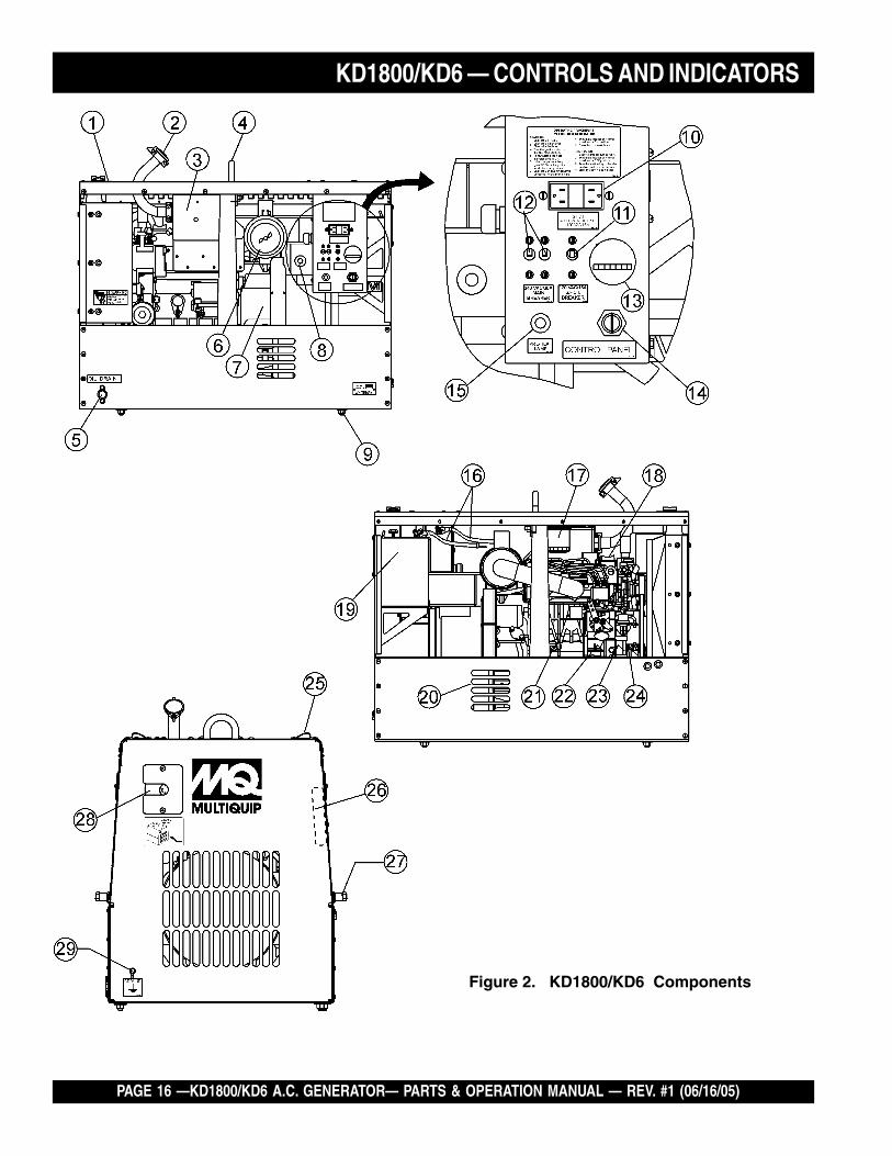
Figure 2. KD1800/KD6 Components
KD1800/KD6 — CONTROLS AND INDICATORS

KD1800/KD6 A.C. GENERATOR — PARTS & OPERATION MANUAL — REV. #1 (06/16/05) — PAGE 17
Figure 2 shows the location of the controls and indicators of theKD1800/KD6 generator. The functions of each control or indicatoris described below:
1. Radiator Filler Port – Remove this plate to add coolant(anti-freeze) to the radiator. NEVER add coolant to theradiator when the radiator is HOT!. Allow the radiator tocool before adding coolant. Use a water coolant mixture asrecommended in the maintenance section of this manual.
2. Air Outlet Exhaust Pipe – Allows engine exhaust to exitthe generator into the open air. NEVER block this opening.
3. Muffler– Used to reduce noise and emissions.
4. Lifting Hook – Use this hook to lift the generator. ALWAYSuse a lifting device of adequate lifting capacity to lift thegenerator.
5. Oil Drain Plug – Remove this plug to drain oil from theengine crankcase. Fill with recommended type oil asspecified in the maintenance section of this manual.
6. Engine Air Cleaner – Prevents dirt and other debris fromentering the fuel system. Lift locking latch on air filter cannisterto gain access to filter element.
7. Marathon Generator – Provides single-phase AC powerfor external equipment. See specification table (Table 1)within this manual.
8. Generator Output Box – Contains the excitationelectronics for the generator.
9. Generator Mounting Hardware – Use this hardware toinstall or remove the generator from the trailer frame.
10. Receptacle G.F.C.I. – Provides 120 volts output at 15amps.
11. Circuit Protector Circuit Breaker – This single pole circuitbreaker provides circuit protection (120V @15 amps) forthe G.F.C.I receptacle.
12. Main Circuit Breaker – This 2-pole circuit breaker providescircuit protection (120/240V @30 amps) for the load side ofthe generator.
13. Hour Meter – Indicates number of hours machine hasbeen in use or hours engine was run.
14. Ignition Switch – With key inserted turn clockwise to startengine.
15. Pre-Heat Indicator Light – Lights blue during enginestart-up. Indicates that engine glow plugs are being pre-heated. Light will go off after approximately 10 seconds.
KD1800/KD6 — CONTROLS AND INDICATORS16. Battery Terminals – Connect these terminals to the battery.
Always pay close attention to the polarity of the terminalswhen connecting to the battery, RED (positive), and BLACK(negative).
17. Fuel Filter – Prevents dirt and foreign debris from enteringthe fuel system. Replace this filter as recommended in themaintenance section of this manual.
18. Engine Oil Filler Port – Remove this cap to add engineoil. Use only recommended type oil. See table 3.
19. Battery – Provides +12 VDC power for the generator. Whenreplacing battery (12V 40 AH) use only recommended typebattery.
20. Air Inlet vent – Allows outside air to enter the generator.NEVER block this opening.
21. Engine Oil Dipstick – Remove this dipstick to determinethe level of the oil in the engine crankcase. For safe engineoperation always maintain the oil between the two notcheson the dipstick. Add recommended type engine oil asspecified in Table 4.
22. Oil Filter – Provides oil filtering for the engine. Replacewith only recommended type oil filter.
23. Primer Bulb – Removes air from the fuel system in theevent the engine has run out of gas.
24. Overflow Bottle – Supplies coolant to the radiator whenradiator coolant level is low. Fill to indicated level as shownon bottle
25. Cabinet Latch – Use this latch to keep cabinet door open.
26. Documentation Box – Operation, parts and servicemanuals are kept in this box.
27. Cabinet Handle – Turn handle clockwise to release lockingmechanism, then pull cabinet door upward to gain accessto engine compartment.
28. Output Receptacle – Remove cover plate to gain accessto receptacle. To receive power from the generator, plugexternal power cable into this receptacle.
29. Frame Ground Lug – Connect a ground strap betweenthis lug and a ground rod. Make sure that the ground rod isinserted deep into the ground to provide a good earthground. Consult with local Electrical and Safety Codes forproper connection.

PAGE 18 —KD1800/KD6 A.C. GENERATOR— PARTS & OPERATION MANUAL — REV. #1 (06/16/05)
KD1800/KD6 — INSTALLATION
Outdoor Installation
Install the generator in a location where it will not be exposedto rain or sunshine. Make sure that the welder/generator ison secure level ground so that it cannot slide or shift around.Also install the generator in a manner so that the exhaustwill not be discharged in the direction of nearby homes.
The installation site must be relatively free from moistureand dust. All electrical equipment should be protected fromexcessive moisture. Failure to do will result in deteriorationof the insulation and will result in short circuits and grounding.
Foreign materials such as dust, sand, lint and abrasivematerials have a tendency to cause excessive wear, notonly to the engine parts, but also to the alternator parts.
CAUTION :
Indoor Installation
Exhaust gases from diesel engines are extremely poisonous.Whenever an engine is installed indoors the exhaust fumesmust be vented to the outside. The engine should be installedat least two feet from any outside wall. Using an exhaustpipe which is too long or too small can cause excessiveback pressure which will cause the engine to heatexcessively and possibly burn the valves.
Eliminate the danger of deadly carbon monoxide gas.Remember that exhaust fumes from any gasoline engineare very poisonous if discharged in a closed room, butharmless if allowed to mix with the outside air. If the generatoris installed indoors, you must make provisions for ventingthe engine exhaust to the outside of the building.
Pay close attention to ventilation whenoperating the generator inside tunnels andcaves. The engine exhaust containsnoxious elements.

KD1800/KD6 A.C. GENERATOR — PARTS & OPERATION MANUAL — REV. #1 (06/16/05) — PAGE 19
General Inspection Prior to Operation
The KD1800/KD6 utilizes a generator that has beenthoroughly inspected and accepted prior to shipment fromthe factory. However, be sure to check for damaged parts orcomponents, or loose nuts and bolts, which could haveoccurred in transit.
Generator Grounding
To guard against electrical shock and possible damage tothe equipment, it is important to provide a good EARTHground.
Article 250 (Grounding) of the National Electrical Code (NEC)provides guide lines for proper grounding and specifies thatthe cable ground shall be connected to the grounding systemof the building as close to the point of cable entry as practical.If a building is not accessible, then the use of a ground rodis sufficient.
KD1800/KD6 — PRE-SETUP (GENERATOR)
NEC articles 250-91a and 250-95 sets the followinggrounding requirements:
1. Use one of the following wire types to connect thegenerator to earth ground.
a. Copper - 10 AWG (5.3 mm2) or larger.
b. Aluminum - 8 AWG (8.4 mm2) or larger.
2. The ground terminal on the generator should always beused to connect the generator to a suitable ground. Theground ring on the generator (Figure 3) should be able toaccommodate #8 size copper or aluminum wire.
3. Crimp the ground wire to the ground lug on the generator.Connect the other end of the ground wire to a suitablebuilding ground or ground rod.
4. NEC article 250-83c specifies that the earth ground rodshould be buried a minimum of 8 ft. into the ground.
When connecting the generator toany buildings electrical systemALWAYS consult with a licensedelectrician.
NOTE
Check local city codes for propergrounding requirements.
NOTE
Figure 3. Generator GroundingConfiguration

PAGE 20 —KD1800/KD6 A.C. GENERATOR— PARTS & OPERATION MANUAL — REV. #1 (06/16/05)
Circuit Breakers
To protect the generator from an overload, a 2-pole, 30 amp,main circuit breaker is provided. In addition a single pole,15 amp breaker is provided for the G.F.C.I. receptacle. Makesure to switch both circuit breakers to the "OFF" positionprior to starting the engine.
Extension Cable
When electric power is to be provided to various tools orloads at some distance from the generator, extension cordsare normally used. Cables should be sized to allow fordistance in length and amperage so that the voltage dropbetween the generator and point of use (load) is held to aminimum. Use the cable selection chart (Table 3 ) as a guidefor selecting proper cable size.
KD1800/KD6 — PRE-SETUP (GENERATOR)
)noitarepOesahPelgniS,zH06(noitceleSelbaCnoisnetxE.3elbaT
nitnerruCserepmA
sttaWnIdaoL htgneLelbaCelbawollAmumixaM
021tAstloV
042tAstloV
eriW01# eriW21# eriW41# eriW61#
5.2 003 006 .tf0001 .tf006 .tf573 .tf052
5 006 0021 .tf005 .tf003 .tf002 .tf521
5.7 009 0081 .tf053 .tf002 .tf521 .tf001
01 0021 0042 .tf052 .tf051 .tf001
51 0081 0063 .tf051 .tf001 .tf56
02 0042 0084 .tf521 .tf57 .tf05
03 0063 0027 .tf57 .tf05 .tf53
.egatlovwolmorftlusernacegamadtnempiuqE:NOITUAC

KD1800/KD6 A.C. GENERATOR — PARTS & OPERATION MANUAL — REV. #1 (06/16/05) — PAGE 21
Lubrication Oil (Engine)
Fill the engine crankcase with lubricating oil through the fillerhole, but do not overfill. Make sure the generator is level.With the dipstick inserted all the way into its holder. Verifythat the oil level is maintained between the two notches(Figure 4) on the dipstick. See Table 4 for proper selection ofengine oil.
Fuel
Fill the fuel tank with No. 2 diesel fuel. DO NOT fill the tankbeyond capacity. Use a strainer when pouring the fuel intothe tank. This will prevent dirt and debris from entering thefuel system.
Pay attention to the fuel tank capacity when replenishingfuel. Refer to the fuel tank capacity listed on page 13, EngineSpecification Table 2.
The fuel tank cap must be closed tightly after filling. Handlefuel in a safety container. If the container does not have aspout, use a funnel.
CAUTION :NEVER fill the fuel tank while the engineis running or in the dark. Diesel fuelspillage on a hot engine can cause a fireor explosion. If diesel fuel spillage occurs,wipe up the spilled gasoline completely toprevent fire hazards.
Coolant
Check coolant level as described in the maintenance section ofthis manual.
Use distilled water mixed with coolant. If hard water or waterwith many impurities is used, the inside of the engine andradiator may become coated with deposits and coolingefficiency will be reduced.
KD1800/KD6 — PRE-SETUP (ENGINE)
Figure 4. Engine Oil Dipstick
liOrotoMdednemmoceR.4elbaT
egnaRerutarepmeT liOepyT
����� )F°77(C°32 ro03EAS03-W01EAS04-W01EAS
°0 �� )F°77ot23(C°52 ro02EAS03-W01EAS04-W01EAS
����� °0 )F°23(C roW01EAS03-W01EAS04-W01EAS

PAGE 22 —KD1800/KD6 A.C. GENERATOR— PARTS & OPERATION MANUAL — REV. #1 (06/16/05)
Fan Belt Tension
A slack fan belt may contribute to overheating, or toinsufficient charging of the battery. Inspect and adjust it inaccordance with the KUBOTA engine manual.
The fan belt tension is proper if the fan belt (Figure 5) bends7 to 9 mm (0.28- to 0.35) when depressed with the thumb asshown in Figure 8 below.
CAUTION :
When adding coolant or anti-freeze to theradiator, DO NOT remove the radiator capuntil the unit has completely cooled.
Figure 5. Fan Belt Tension
RadiatorDay-to-day addition of coolant or anti-freeze is done via thereserve tank. See maintenance section (radiator) of thismanual for filling requirements.
Cleaning the RadiatorThe radiator may overheat if the fins become overloadedwith dust or debris. Periodically clean the radiator fins withcompressed air.
KD1800/KD6 — PRE-SETUP (ENGINE)

KD1800/KD6 A.C. GENERATOR — PARTS & OPERATION MANUAL — REV. #1 (06/16/05) — PAGE 23
KD1800/KD6 — INSTRUMENTATION
Power Outlets
The generator has the following single-phase 60 Hz, 120/240 volt receptacles.
Single Phase
One Duplex NEMA (GFCI) 5-15R (120V, 15 Amp)
One Twist Lock NEMA L14-30R (120/240V, 30 Amp)
Main Circuit Breaker (2-Pole)
This 2-pole, 30 amp main breaker protects the 120/240output receptacle from short circuiting or overloading.
GFCI Circuit Breaker (Single-Pole)
This single-pole, 15 amp breaker protects the GFCIreceptacle from short circuiting or overloading.
GFCI Receptacle
Before connecting a load to the generator's GFCI receptacle,push the "Test Button" on the front of receptacle beforeconnecting the load, to confirm that the receptacle isfunctioning correctly.
Pre-Heat Lamp
Lights blue during engine start-up. Indicates that engine glowplugs are being pre-heated. Light will go off afterapproximately 10 seconds.
CAUTION :When using a combination of dualreceptacles, total load should not exceedthe rated capacity of the generator set.

PAGE 24 —KD1800/KD6 A.C. GENERATOR— PARTS & OPERATION MANUAL — REV. #1 (06/16/05)
KD1800/KD6 — LOAD APPLICATIONSingle Phase Load
Always be sure to check the nameplate on the generatorand equipment to insure the wattage, amperage andfrequency requirements are satisfactorily supplied by thegenerator for operating the equipment.
Generally, the wattage listed on the nameplate of theequipment is its rated output. Equipment may require 130—150% more wattage than the rating on the nameplate, asthe wattage is influenced by the efficiency, power factor andstarting system of the equipment.
CAUTION:Motors and motor-driven equipment drawmuch greater current for starting thanduring operation.
An inadequate size connecting cable which cannot carrythe required load can cause a voltage drop which can burnout the appliance or tool and overheat the cable.
CAUTION:Before connecting this generator to anybuilding’s electrical system, a licensedelectrician must install an isolation(transfer) switch. Serious injury or deathmay result without this transfer switch.
NOTEIf wattage is not given on theequipment's name plate, approximatewattage may be determined bymultiplying nameplate voltage by thenameplate amperage.
WATTS = VOLTAGE x AMPERAGE
The power factor of this generator is 1.0. See Table 5 belowwhen connecting loads.
daoLyBrotcaFrewoP.5elbaT
daoLfOepyT rotcaFrewoP
srotomnoitcudniesahp-elgniS 57.0-4.0
tnecsednacni,sretaehcirtcelEspmal 0.1
spmalyrucem,spmaltnecseroulF 9.0-4.0
noitacinummoc,secivedcinortcelEtnempiuqe 0.1
When connecting ordinary power tools, a capacity ofup to the generating set’s rated output (kW) multipliedby 0.8 can be used.When connecting a resistance load such as anincandescent lamp or electric heater, a capacity of upto the generating set’s rated output (kW) can be used.
When connecting a fluorescent or mercury lamp, acapacity of up to the generating set’s rated output (kW)multiplied by 0.6 can be used.
When connecting an electric drill or other power tools,pay close attention to the required starting currentcapacity.

KD1800/KD6 A.C. GENERATOR — PARTS & OPERATION MANUAL — REV. #1 (06/16/05) — PAGE 25
KD1800/KD6 — ENGINE OPERATING INSTRUCTIONS
WARNING:WARNING:WARNING:WARNING:WARNING:
Before Starting
1. Be sure to disconnect the electrical load and switchthe main circuit breaker to the "OFF" position prior tostarting the engine. Also switch the GFCI circuit breakerto the "OFF" position.
2. NEVER start the engine with the main or GFCI circuitbreakers in the “ON” position.
3. Check the lubricating oil level prior to starting the engine.Make sure the generator is level. The oil level must bemaintained between two notches on the dipstick.
4. When there is not enough lubricating oil, fill the crankcasewith high grade motor oil. Use a high quality detergentoil classified CC or higher (See Table 4 on page 21).
5. Check the coolant level in the radiator and subtank.Replenish with anti-freeze as necessary. ALWAYSmaintain the coolant level between the FULL and LOWmarkings on the coolant container. Be sure that theradiator cap is fastened securely.
CAUTION:CAUTION:CAUTION:CAUTION:CAUTION:Check the fuel source for low fuel level.When fuel is low, fill the fuel tank withclean fresh automotive No. 2 diesel fuel.
If diesel fuel spillage occurs, completelywipe up the spilled diesel fuel.
The engine's exhaust contains harmfulemissions. ALWAYS ventilate theexhaust when operating inside tunnels,excavations or buildings. Direct exhaustaway from nearby personnel.
Engine Starting Procedure (Diesel)
1. ALWAYS operate the generator with the doors in theclosed position. Operation with the doors open maycause insufficient cooling to the unit, and damage mayresult.
2. Insert the key into the ignition switch and turn it counter-clockwise to the "PRE-HEAT" position.
3. When the "PRE-HEAT" lamp goes off, turn the key toclockwise to the ”START” position. As soon as theengine starts, release the key.
4. If the engine does not start within 10 seconds after thekey is turned to the “START” position, wait for about 30seconds and repeat the procedure as described in steps1 through 4.
5. Let the engine idle for five minutes with no load
6. If any abnormal vibrations, noises or oil leakages occur,turn the generator OFF immediately and rectify theproblem.
7. If the generator is running smoothly with no problemsconnect the load (output power cable) to the generator.
Engine Shut-down Procedure
1. Remove the load from the generator, then place boththe main and GFCI circuit breakers to the OFF position.
2. Listen for the engine speed to drop. Run at low speedfor 3-5 minutes.
3. Stop the engine by turning the key to the “CENTER”position and remove the key. Store key in a safe place.
NEVER turn the key to the “START”position while the engine is running.
CAUTION:CAUTION:CAUTION:CAUTION:CAUTION:
NOTEDuring winter or when the surrounding airtemperature is cold, in situations where acold start is required, turn the key to the"HEAT" position. Remember you mustwait until the preheat light goes off beforeturning the key to the start position.

PAGE 26 —KD1800/KD6 A.C. GENERATOR— PARTS & OPERATION MANUAL — REV. #1 (06/16/05)
General Inspection
At least daily or prior to each use, the generator should becleaned and inspected for deficiencies. Check for loose,missing or damaged nuts, bolts or other fasteners. Also checkfor fuel or oil leaks.
Engine Side:
For a more detail engine maintenance schedule refer to theKUBOTA Engine Shop and Operator's Manual.
Air Cleaner
Every 50 hours: The air cleaner employed on the KUBOTAengine Model D905EBG is a dry type, NEVER apply oil toit.
If the generator will be operating in very dusty and dry grassconditions, a clogged air cleaner will result in high fuelconsumption, loss of power and excessive carbon buildupin the combustion chamber. Service air cleaner daily.
1. Open the evacuator valve (Figure 6) once a week underordinary conditions or daily in dusty conditions. This willeliminate large particles of dust and dirt within the aircleaner.
KD1800/KD6 — MAINTENANCE (ENGINE)
Figure 6. Air Cleaner
2. Wipe the inside of the air cleaner with a damp clothand remove all dust and debris that may haveaccumulated inside air cleaner body.
3. Avoid touching the element except when cleaning.
4. Use compressed air to clean air filter element. Blowcompressed air from the inside while turning the element.ALWAYS keep the pressure of the compressed air below99 psi.
5. If carbon or oil adheres to the element, soak the elementin detergent for 15 minutes, then wash it several timesin water, rinse with clean water and let dry.
CAUTION:CAUTION:CAUTION:CAUTION:CAUTION:
6. After the element is fully dried, inspect the inside of theelement with a light, and check for damage (refer to theinstructions on the label attached to the element).
7. Replace the element once a year or every six cleanings.
Make sure the wing nut for the air cleaneris tight enough. If is loose, dust and dirtmay be sucked in, wearing down thecylinder liner and piston ring, and therebyresulting in poor power output.
DO NOT over service the air cleaner element. Overservicing may cause dirt to enter the engine causingpremature wear. Use the dust indicator as a guide onwhen to service the element.
Oil Change
Every 200 hours: Change the engine oil after the first 50hours of operation and every 200 hours thereafter. ALWAYScheck the crankcase oil level prior to each use, or when thefuel tank is filled. Insufficient oil may cause severe damageto the engine. Make sure the generator is level when checkingthe oil level.
1. Remove the oil dipstick from its holder, wipe it cleanand reinstall it.
2. Remove the oil dipstick again from its holder, and checkthe oil level.
3. The oil level must be between the two notches on thedipstick as shown in Figure 7.
Figure 7. Engine Oil Dipstick

KD1800/KD6 A.C. GENERATOR — PARTS & OPERATION MANUAL — REV. #1 (06/16/05) — PAGE 27
4. If the engine oil level is too low, remove the engine oilfiller cap Figure 9, and fill to the correct operating level.
Figure 9. Engine Oil Filler Hole
CAUTION:CAUTION:CAUTION:CAUTION:CAUTION:
Engine oil should be MIL-L2104C orhave properties of API classificationCD grades or higher.
When changing the engine oil, use a oil with a viscosityappropriate for the atmospheric temperature at the site.Use SAE-30 oil in the summer, SAE-20 in the winter, orall season SAE 10W-30 oil which offers stable viscosityat various ambient temperatures. See Table 4 .
When different type oil brands are used, be sure to drainall the previous oil before adding the new engine oil.
Oil Cartridge
Every 200 hours: Replace the engine oil filter cartridge(Figure 10) after every 200 hours of operation.
KD1800/KD6 — MAINTENANCE (ENGINE)
Figure 10. Oil Filter Cartridge
Fuel Lines
Every 50 hours: Check the fuel lines and associated clampbands every 50 hours of operation.
1. If the rubber fuel lines and clamp bands become worn,replace them immediately. Replace all rubber fuel linesevery two years.
Replacing the Fuel Filter
Every 400 hours: Replace the fuel filter (Figure 11) every400 hours.
Figure 11. Fuel Filter
The fuel tank for this generator is containedwithin the trailer section of the ModularLight Tower (MLT).
NOTE
1. Remove the old oil filter cartridge with a filter wrench.
2. Apply a film of oil to the gasket for the new cartridge.
3. Screw the new cartridge in by hand. DO NOT use thefilter wrench to tighten the new filter.
4. Run the engine for a few minutes, check for leaks. Checkengine oil level, add oil if necessary.
Fuel Addition
When adding diesel fuel to the fuel tank, the grade may varyaccording to season and locations. Typically use No. 2 dieselfuel will filling the fuel tank. Always pour through a meshfilter, this will prevent sand and dirt from entering the fuelsystem.
Removing Water (Condensation) from the Fuel TankAfter prolonged use, water and other impurities accumulatein the bottom of the tank. Occasionally remove the draincock and drain the contents. During cold weather, the moreempty area inside the tank, the easier it is for water toaccumulate. This can be reduced by always keeping thetank as full as possible.

PAGE 28 —KD1800/KD6 A.C. GENERATOR— PARTS & OPERATION MANUAL — REV. #1 (06/16/05)
KD1800/KD6 — MAINTENANCE (ENGINE)
Air Removal
If air enters the fuel system of a diesel engine, startingbecomes impossible. After running out of fuel, or afterdisassembling the fuel system, bleed the system accordingto the following procedure.
To restart after running out of fuel, turn the key switch to the“START” position for 15-30 seconds. Try again, if needed.This unit is equipped with an automatic air bleeding system.
Radiator
Check Daily: Coolant will last for one day's work if filled tothe maximum level.
CAUTION:CAUTION:CAUTION:CAUTION:CAUTION:
NEVER remove the radiator cap while the coolant ishot! Let radiator cool before removing cap. Severe burnsand bodily injury could result from removing the radiatorcap when the radiator is hot.
NEVER stop engine suddenly to add coolant, let engineidle for 3-5 minutes with no load. Then shut-down engineand let cool.
Checking Coolant Level
1. Remove the radiator cap (Figure 12) only after the enginehas completely cooled, and check to see that the coolantreaches the supply port.
2. Check the coolant level in the reserve tank, (Figure 13),make sure it is filled to the "FULL" marking with coolant.The coolant will last for one days work if filled to the"FULL" mark. Replenish coolant as coolant approaches"LOW" marking on reserve tank.
3. DO NOT refill the reserve tank with coolant beyond the"FULL" marking.
Figure 12. Radiator
Figure 13. Reserve Tank
Adding Coolant/Anti-freeze
Day-to-day addition of coolant or antifreeze is done via thereserve tank. See Table 6 for engine/radiator and reservetank coolant capacities and Table 7 for coolant operatingtemperatures. Make sure that the coolant level in the reservetank is always between the "FULL" and the "LOW" markings.
yticapaCtnalooC.6elbaT
rotaidaRdnaenignE sretiL1.3).laG28.0(
knaTevreseR )kraMlluF(sretiL6.
serutarepmeTgnitarepOezeerF-itnA.7elbaT
%loVezeerF-itnA
tnioPgnizeerF tnioPgnilioB
C° F° C° F°
04 42- 21- 601 222
05 73- 43- 801 622

KD1800/KD6 A.C. GENERATOR — PARTS & OPERATION MANUAL — REV. #1 (06/16/05) — PAGE 29
KD1800/KD6 — MAINTENANCE (ENGINE)
When the anti-freeze is mixed withwater, the anti-freeze mixing ratiomust be less than 50%.
NOTE
Anti-freeze Recommendations
Use rubber gloves when handling anti-freeze.
When anti-freeze comes in contact with the skin orclothing, wash it off immediately.
DO NOT mix different types of anti-freeze.
Keep fire, children and animals away from anti-freeze.
Check with local safety codes on the proper disposaltechniques of anti-freeze.
The battery is sufficiently charged if the specific gravity ofthe battery fluid is 1.28 (at 68° F). If the specific gravityshould fall to 1.245 or lower, it indicates that the battery isdead and needs to be recharged or replaced.
Check to see whether the battery cables are loose. Poorcontact may result in poor starting or malfunctions, alwayskeep the terminals firmly tightened. Coating the terminalswith a thin film of grease will help to inhibit corrosion.
The battery gradually deteriorates over time. The actual lifespan will vary according to operating conditions, but generallya battery two years or older should be replaced.
1. Make sure each electrolyte level (Figure 14) is to thebottom of the vent well. If necessary add distilled waterin a well-ventilated area.
Battery
CAUTION:CAUTION:CAUTION:CAUTION:CAUTION:
NEVER let the battery's electrolytecontact your body or clothing. ALWAYSwear gloves when handling the battery.
ALWAYS wear eye protection andrubber gloves when handling thebattery. Remember the dilutedsulfuric acid solution within thebattery burns skin and eats holesin clothing.
If any part of your body comes in contact with thesulfuric acid of the battery, immediately wash it off withrunning water and get medical attention.
This unit is of negative ground. DO NOT connect in reverse.Always maintain battery fluid level between the specifiedmarks. Battery life will be shortened, if the fluid level is notproperly maintained. Add only distilled water whenreplenishment is necessary.
ALWAYS follow safety rules whenhandling the battery. NEVER charge thebattery in a flammable environment.ALWAYS keep open sparks and flamesaway from the battery at all the times. Figure 14. Battery Electrolyte
Level
Direction For Long Term Storage (Battery)
1. Remove the battery from the generator. Adjust theelectrolyte to the correct level, and store in a dry anddark place.
2. Recharge battery once a month in summer, and everytwo months in winter.

PAGE 30 —KD1800/KD6 A.C. GENERATOR— PARTS & OPERATION MANUAL — REV. #1 (06/16/05)
KD1800/KD6 — MAINTENANCE (GENERATOR)
GeneratorCapacitor RegulationA single capacitor is used to regulate the voltage to within5% of the rated load.
ALWAYS USE EXTREME CAUTION when handlingcapacitors. The capacitor will still contain a high voltageeven after the engine has been shut-down.
ALWAYS discharge the capacitor before handling. Usea conductor or a screwdriver (Figure 15) with an insulatedhandle. Place screwdriver across both capacitorterminals while holding onto the handle. This will shortout the voltage and discharge the capacitor.
Checking the Charge of the Capacitor
1. Use an "OHMMETER" to check the charge anddischarge of the capacitor. Set the ohmmeter to theRX-1000 scale.
2. Place the ohmmeter leads on the capacitor terminalsone at a time. A meter deflection should be seen(charging), followed by a slow return to infinity(discharging).
3. Reverse the ohmmeter leads and repeat the procedure.The results should be the same. Replace the capacitorif no meter deflection or continuity has been indicatedby the ohmmeter.
Flashing Rotor Procedure
1. Disconnect all incoming power leads to the generator.
2. Connect the (+) lead of a 12 volt battery to the "R"connection (Figure 16).
Figure 15. Discharging Capacitor3. Connect the (-) lead of the battery to the rotor shaft.
4. Re-connect all incoming power leads to the generator
5. Start the generator as outlined in the "OperatingSection" of this manual.
6. With a voltmeter check the no load voltage at the 120/240 output connector located on the control box.
7. The no load should be within 10% of the rated load.
8. If residual voltage is normal, the capacitor is defectiveand should be replaced.
Diode Check
1. Check the diode individually by removing the (+) rotorlead stud connection (Figure 16). The diode is good ifthe resistance reading is approximately mid -scale onthe lowest ohm scale.
2. Check for leakage in the diode by reversing the polarity.The diode is good if the resistance reading is infinite.
3. A faulty diode will give a resistance value of zero.
Figure 16. Flashing The Rotor Configuration
DO NOT run the generator during thisprocedure.
NOTE
KD1800/KD6 A.C. GENERATOR — PARTS & OPERATION MANUAL — REV. #1 (06/16/05) — PAGE 31
Generator Storage
For storage of the generator for over 30 days, the followingis required:
Drain the fuel tank completely.
Completely drain the oil from the crankcase and refillwith fresh oil.
Disconnect the negative battery cable from the battery.
Clean all external parts of the generator with a cloth.
Cover the generating set and store in a clean, dry place.
KD1800/KD6 — PREPARATION FOR LONG -TERM STORAGE

PAGE 32 —KD1800/KD6 A.C. GENERATOR— PARTS & OPERATION MANUAL — REV. #1 (06/16/05)
KD1800/KD6 — TROUBLESHOOTING ( GENERATOR)
Practically all breakdowns can be prevented by properhandling and maintenance inspections, but in the event of abreakdown, please take a remedial action following the
diagnosis based on the Generator Troubleshooting (Table 8)information shown below . If the problem cannot be remedied,please leave the unit just as it is and consult our company'sbusiness office or service plant.
GNITOOHSELBUORTROTARENEG.8ELBAT
NOTPMYS MELBORPELBISSOP NOITULOS
.egatlovdlohtonlliW
?gnolootderotsneebrotarenegsaH .erudecorp"rotoRhsalF"mrofreP
?tohstegrotarenegnehwtuognitrohsrotoR .seriwdenrubronekorbrofsgnidniwrotorkcehC
?sdaeleriwdehcniP .yrassecensaecalpeR.sdaeleriwllaenimaxE
?roticapacevitcefeD .ecalpeR
?sedoidevitcefeD .sedoidecalpeR
-daolontaegatlovlluF.daollluftaspordegatlov
?sdaeleriwnekorbroesooL ?snoitcennocdnaseriwdaelkcehC
?detrohsroneporotoR .sdaelneewtebecnatsisererusaeM
?detrohsrodednuorgrotatS .yrotcaftlusnoC
WOLootegatloV?msitengamlaudiserfossoL .erudecorp"rotoRhsalF"mrofreP
?deepsenignewoL .zH06,s'mpr0081otdeepsenigneteS
HGIHootegatloV ?deepsenignetsaF .zH06,s'mpr0081otdeepsenigneteS
egatloVelballortnocnU ?tnemtsujdaenignetcerrocnI .srotcejnidnasenilleuf,deeps,noitarepoenignekcehC
ro"daol-on"taegatlovoN"daollluf"
?rosserppusytluaFesaercnisuoivbonasierehtfI.tiucricmorftcennocsiD
.rosserpusecalper,egatlovni
gniraeppasekipsegatloV.evawenisni
?sagroopro,enilleuf,tnemtsujdaenignetcerrocnI .deepsenignekcehcdnaretlifleufegnahC
?noitcennocesooL .snoitcennocllatcepsnI
?noitcennocdnuorgdaB .snoitcennocdnuorgllatcepsnI

KD1800/KD6 A.C. GENERATOR — PARTS & OPERATION MANUAL — REV. #1 (06/16/05) — PAGE 33
KD1800/KD6 — TROUBLESHOOTING (ENGINE)
GNITOOHSELBUORTENIGNE.9ELBAT
MOTPMYS MELBORPELBISSOP NOITULOS
.tratstonseodenignE
?leufoN .leufhsinelpeR
?metsysleufehtniriA .metsysdeelB
?metsysleufehtniretaW .knatleufmorfretawevomeR
?deggolcepipleuF .epipleufnaelC
?deggolcretlifleuF .retlifleufegnahcronaelC
foytisocsivhgihylevissecxEwoltalioenigneroleuf
?erutarepmet.lioenigneroleufdeificepsehtesU
?rebmunenatecwolhtiwleuF .leufdeificepsehtesU
noitcejniesooloteudkaelleuF?tungniniaterepip .tunnethgiT
?gnimitnoitcejnitcerrocnI .tsujdA
?nrowtfahsmacleuF .ecalpeR
?deggolcelzzonnoitcejnI .elzzonnoitcejninaelC
?gninoitcnuflampmupnoitcejnI .ecalperroriapeR
,tfahsmac,tfahsknarcfoeruzieS?gniraebrorenilrednilyc,notsip .ecalperroriapeR
morfkaelnoisserpmoC?rednilyc
dnagulpwolg,tlobdaehrednilycnethgit,teksagdaehecalpeR.redlohelzzon
?gnimitevlavreporpmI .raeggnimitecalperrotcerroC
?nrowrenildnagnirnotsiP .ecalpeR
?ecnaraelcevlavevissecxE .tsujdA
.nurtonseodretratS
?degrahcsidyrettaB .yrettabegrahC
?gninoitcnuflamretratS .ecalperroriapeR
?gninoitcnuflamhctiwsyeK .ecalperroriapeR
?detcennocsidgniriW .gniriwtcennoC
diagnosis based on the Engine Troubleshooting (Table 9)information shown below and on the proceeding page . If theproblem cannot be remedied, please leave the unit just as itis and consult our company's business office or serviceplant.
Practically all breakdowns can be prevented by properhandling and maintenance inspections, but in the event of abreakdown, please take a remedial action following the

PAGE 34 —KD1800/KD6 A.C. GENERATOR— PARTS & OPERATION MANUAL — REV. #1 (06/16/05)
KD1800/KD6 — TROUBLESHOOTING (ENGINE)
)DEUNITN0C(GNITOOHSELBUORTENIGNE.9ELBAT
MOTPMYS MELBORPELBISSOP NOITULOS
.htoomstonsinoituloverenignE
?ytridrodeggolcretlifleuF .egnahcronaelC
?deggolcrenaelcriA .egnahcronaelC
noitcejniesooloteudkaelleuF?tungniniaterepip .tunnethgiT
?gninoitcnuflampmupnoitcejnI .ecalperroriapeR
gninepoelzzontcerrocnI?erusserp .tsujdA
rokcutselzzonnoitcejnI?deggolc .ecalperroriapeR
?deggolcepipwolfrevoleuF .naelC
?gninoitcnuflamronrevoG .riapeR
sagtsuahxeeulbroetihwrehtiE.devresbosi
?lioenigneevissecxE .leveldeificepsehtotecudeR
ronrowrenildnagnirnotsiP?kcuts .ecalperroriapeR
?gnimitnoitcejnitcerrocnI .tsujdA
?noisserpmoctneicifeD .ecnaraelcpottsujdA
yargkradrokcalbrehtiE.devresbosisagtsuahxe
?daolrevO .daolehtnesseL
?desuleufedargwoL .leufdeificepsehtesU
?deggolcretlifleuF .egnahcronaelC
?deggolcrenaelcriA .egnahcronaelC
?noitcejnielzzontneicifeD .elzzonehtecalperroriapeR
.tuptuotneicifeD
?gnimitnoitcejnitcerrocnI .tsujdA
otmeesstrapgnivoms'enignE?gnizieseb .ecalperroriapeR
?noitcejnileufnevenU .pmupnoitcejniehtecalperroriapeR
?noitcejnielzzontneicifeD .elzzonehtecalperroriapeR
?kaelnoisserpmoC dnagulpwolg,tlobdaehrednilycnethgit,teksagdaehecalpeR.redlohelzzon

KD1800/KD6 A.C. GENERATOR — PARTS & OPERATION MANUAL — REV. #1 (06/16/05) — PAGE 35
NOTE PAGE

PAGE 36 —KD1800/KD6 A.C. GENERATOR— PARTS & OPERATION MANUAL — REV. #1 (06/16/05)
How to read the marks and remarks used in this parts book.
Section 1: Items Found In the “Remarks” Column
Serial Numbers-Where indicated, this indicates a serialnumber range (inclusive) where a particular part is used.
Model Number-Where indicated, this shows that thecorresponding part is utilized only with this specific modelnumber or model number variant.
Section 2: Items Found In the “Remarks” Column
Serial Numbers-Where indicated, this indicates a serial numberrange (inclusive) where a particular part is used.
Model Number-Where indicated, this shows that thecorresponding part is utilized only with this specific model numberor model number variant.
Section 3: Items Found In the “Items Number” Column
All parts with same symbol in the number column, *, #, +, %, or■, belong to the same assembly or kit.
Note: If more than one of the same reference number is listed,the last one listed indicates newest (or latest) part available.
NOTE
The contents of this parts catalog are subject tochange without notice.
KD1800/KD6 — EXPLANATION OF CODES IN REMARKS COLUMN

KD1800/KD6 A.C. GENERATOR — PARTS & OPERATION MANUAL — REV. #1 (06/16/05) — PAGE 37
KD1800/KD6 W/KUBOTA D905EBG-2DIESEL ENGINE 1 TO 3 UNITSQty. P/N Description5 ............ 1627132092 .......... OIL FILTER2 ............ 1491197010 .......... V-BELT1 ............ 1522443013 .......... FUEL FILTER5 ............ 29334 .................... OIL PRESSURE SENSOR5 ............ 29333 .................... WATER TEMPERATURE SENSOR1 ............ 20511 .................... IGNITION SWITCH2 ............ 12940 .................... KEYS1 ............ 29344 .................... TIMER GLOW PLUG1 ............ 1624173350 .......... BYPASS HOSE1 ............ 1626672941 .......... UPPER RADIATOR HOSE1 ............ 1628672851 .......... LOWER RADIATOR HOSE1 ............ 1661611013 .......... AIR CLEANER1 ............ 29343 .................... DUPLEX OUTLET1 ............ 19212 .................... HOUR METER1 ............ 19223 .................... CIRCUIT BREAKER 30 AMP1 ............ 2673 ...................... CIRCUIT BREAKER 20 AMP
KD1800/KD6 — SUGGESTED SPARE PARTS
NOTE
Part numbers on this SuggestedSpare Parts List may supercede/replace the P/N shown in the textpages of this book.

PAGE 38 —KD1800/KD6 A.C. GENERATOR— PARTS & OPERATION MANUAL — REV. #1 (06/16/05)
KD1800/KD6 — NAMEPLATE AND DECALS

KD1800/KD6 A.C. GENERATOR — PARTS & OPERATION MANUAL — REV. #1 (06/16/05) — PAGE 39
KD1800/KD6 — NAMEPLATE AND DECALS
ENCLOSURE ASSY.
NO. PART NO. PART NAME QTY. REMARKS1* DCL103 DECAL: LIFTING HOOK 12* DCL117 DECAL: CAUTION SHUT-DOWN GENERATOR 13* DCL180 DECAL: WARNING DANGEROUS FUMES 14* DCL181 DECAL: CAUTION HOT PARTS, BURN SKIN 15* DCL182 DECAL: WARNING MOVING PARTS 26* DCL183 DECAL: HOT COOLANT 17* DCL184 DECAL: WARNING DIESEL FUEL 18* DCL185 DECAL: GROUND 19* DCL186 DECAL: GFCI, 120 VAC POWER, 15A OUTPUT 110* DCL187 DECAL: DANGER DO NOT TOUCH WIRING 211* DCL188 DECAL: OPERATE WITH DOORS CLOSED 212* DCL189 DECAL: 240 VAC/30A MAIN BREAKER 113* DCL190 DECAL: PRE-HEAT LAMP 114* DCL191 DECAL: DANGER EXPLOSIVE GAS 115* DCL192 DECAL: OIL DRAIN 116* DCL193 DECAL: CAUTION CHECK OIL LEVEL 117* DCL194 DECAL: CAUTION CHECK COOLANT LEVEL 118* DCL195 DECAL: OPERATING PROCEDURE 119* DCL196 DECAL: PLUG IN FLOOD LIGHT CABLE 120* DCL197 DECAL: OPERATE 1800 RPM 121* DCL198 DECAL: CONTROL PANEL 122* DCL199 DECAL: 120 VAC/15A GFCI BREAKER 123 29360 DECAL: MQ MULTIQUIP 224 29358 DECAL: MQ MULTIQUIP MLT-KD1800 (RIGHT) ................ 1 ....... UP TO S/N FK300005124 29358 DECAL: MQ MULTIQUIP MLT-KD6 1800 RPM (RIGHT) 125 29359 DECAL: MQ MULTIQUIP MLT-KD1800 (LEFT) .................. 1 ....... UP TO S/N FK300005125 29359 DECAL: MQ MULTIQUIP MLT-KD6 1800 RPM (LEFT) 126 DECAL: NAMEPLATE ........................................................ 1 ....... CONTACT MQ SERVICE
....................................................................................................... DEPT. W/MODEL AND S/N27 29345 DECAL: KIT ........................................................................ 1 ....... INCLUDES ITEMS/*SEE DECAL ILLUSTRATIONS ON PAGES 10 AND 11

PAGE 40 —KD1800/KD6 A.C. GENERATOR— PARTS & OPERATION MANUAL — REV. #1 (06/16/05)
KD1800/KD6 — ENCLOSURE ASSY.
ENCLOSURE ASSY.

KD1800/KD6 A.C. GENERATOR — PARTS & OPERATION MANUAL — REV. #1 (06/16/05) — PAGE 41
KD-1800 /KD-6 — ENCLOSURE ASSY.
ENCLOSURE ASSY.
NO. PART NO. PART NAME QTY. REMARKS1 0131A SCREW, HHC 1/4-20 32 0447 WASHER, FLAT 1/2 SAE 43 0948 WASHER FLAT, 1/4 SAE 114 10024 NUT, NYLOC 1/4-20 175 10031 WASHER, EXT SHKP 1/4 16 10176 NUT, NYLOC 1/2-13 47 10981 TERMINAL, RING 12 GA. X .312 INS 18 12287 SCREW, THP 1/4-20 X 3/4 SS 429 19266 RIVNUT 1/4-20 2910 2691 SCREW, HHC 1/2-13 X1 411 29057 DOCUMENT BOX, (CP90007-07) 112 29258 COVER, POWER CORD 113 29260 SUPPORT, RIGHT-LEG 114 29262 SUPPORT, LEFT-LEG 115 29281 HOLD BACK, DOOR AUSTIN 5601-4 216 29282 HANDLE, DOOR T-LOCKING 217 29284 CAM, DOOR HANDLE 218 29285 SPACER, DOOR HANDLE 219 29291 COVER, RADIATOR CAP ACCESS 120 29297 BASE, GEN SET W/A 121 29298 PANEL, FRONT CABINET KD, W/A 122 29299 PANEL. CABINET REAR, W/A 123 29300 TOP, CABINET KD W/A 124 29316 DOOR, KD1800 LEFT W/A 125 29324 BRACKET, RADIATOR LEFT 126 29340 DOOR, KD1800 RIGHT W/A 127 29341 RIVET, POP 3/16" DIA X 1/4-3/8 SS 1628 29342 WASHER, 3/16" SS (POP RIVET SS 1629 29438 KEY, CABINET KD1800/KD6 231 3214 SCREW, HHC 1/2-13 X 1-1/4 432 4514 SCREW, HHC 1/4-20 X 5/8 333 5054A WASHER, LOCK, 1/2 MED 434 0181B WASHER, LOCK MED 2

PAGE 42 —KD1800/KD6 A.C. GENERATOR— PARTS & OPERATION MANUAL — REV. #1 (06/16/05)
KD1800/KD6 — CONTROL BOX ASSY.
CONTROL BOX ASSY.
STARTER
SWITCH
CO
NTACT
STARTDEMARRAGE
PR
EH
EAT
PR
EC
HA
UFFA
GE
AC INPUTWIRING
BACK VIEW
FRONTVIEW
CABINETTOP
222
24
25
10
17
9
7
14
12
11
13
24
3
28
23
23
4 1 3
13
20
NOTES:
1 INCLUDED WITH ITEM 25
2
2
2
26
1
INCLUDED WITH ITEM 7
3 INCLUDED WITH ITEM 14
3
15
218
8
8
2413
27
19
18
20
5
6
16

KD1800/KD6 A.C. GENERATOR — PARTS & OPERATION MANUAL — REV. #1 (06/16/05) — PAGE 43
KD1800/KD6 — CONTROL BOX ASSY.CONTROL BOX ASSY.
NO. PART NO. PART NAME QTY. REMARKS1 0948 WASHER, FLAT, 1/4 SAE 22 10019 NUT, NYLOC 10- 32 43 10024 NUT, NYLOC 1/4- 20 24 10031 WASHER, EXT. SHKP 1/4 15 26560 NUT, LOCKING 3/4 NPT CONDUIT 16 12307 +12 DCV BULB ASSY. 17 29363 LIGHT, BLUE INDICATOR .75 DIA. 18 12287 SCREW, THP 1/4- 20 X 3/4 SS 99 1450 WASHER, FLAT # 6 SAE 610 19212 HOUR METER ISSPRO R8861HV 111 19223 CIRCUIT BREAKER, 30A 277V 212 29376 CIRCUIT BREAKER, 15A, 277 VAC 113 19266 RIVNUT 1/4- 20 914 19695 CONN. STRAIN RELIEF, .625 TO .750 115 6900446 SEAL RING .755 ID 116 6900447 STRAIN RELIEF 117 19819 SCREW, PAN HEAD 6- 32 X 1/4 618 2673 CIRCUIT BREAKER (RE-SETTABLE), 30A, 12V 119 29276 RECEPTACLE, 30A, 120/250 VAC 120 29277 PANEL, CONTROL 121 29325 SHROUD, CONTROL PANEL ASSEMBLY 122 29343 DUPLEX OUTLET, 15A 120V GFCI 123 4514 SCREW, HHC 1/4-20 X 5/8 224 5065B SCREW, RHM 10- 32 X 1/2 625 20511 SWITCH, IGNITION W KEYS 126 12940 KEY SET (KUBOTA) 127 20486 DECAL, START 128 29344 TIMER, GLOW PLUG (B905 KUBOTA) 1

PAGE 44 —KD1800/KD6 A.C. GENERATOR— PARTS & OPERATION MANUAL — REV. #1 (06/16/05)
KD1800/KD6 — ENGINE MOUNTING HARDWARE ASSY.
ENGINE MOUNTING HARDWARE ASSY.
12
3
4
5
6
8
7
5
6
9
10
11
12
6
14
19
14
1215
20
16
17
18
NOTES:
ROUTE ENGINE CABLE HARNESS
THROUGH CLAMPS.1
1
15
6
12
1
2
6
19
USED WITH SERIAL NUMBERS
UP TO S/N FK300000512
2
BASE AND CRADLESHOWN P/N 29297
CRADLEP/N 29263 3
ENGINE CRADLE CANNOT BEPURCHASED SEPARATELY.ORDER P/N 29297 FOR ENGINECRADLE AND BASE.
3
CRADLE ISWELDED
TO BASE

KD1800/KD6 A.C. GENERATOR — PARTS & OPERATION MANUAL — REV. #1 (06/16/05) — PAGE 45
KD1800/KD6 — ENGINE MOUNTING HARDWARE ASSY.ENGINE MOUNTING HARDWARE ASSY.
NO. PART NO. PART NAME QTY. REMARKS1 10133 NUT, NYLOC 3/8"-16 52 29336 WASHER SNUBBING, 2.00 O.D. x .45 I.D. 43 29297 BASE ENG. SET W/A ....................................................... 1 ........... CRADLE P/N 29263 IS
........................................................................................................ WELDED TO BASE4 29269 MOUNT, VIBRATORY ENGINE 45 4370 SCREW, HHC 3/8"-16 x 2-1/4 46 4001 WASHER, FLAT 3/8" PLTD, STD. USS 87 0655 SCREW, HHC 5/16" x 18 x 1 88 0161C WASHER, LOCK, 5/16 MED 89 29270 BRACKET, GENERATOR MOUNT 110 29292 MOUNT, ENGINE (D905BG) 211 0205 SCREW, HHC 3/8" x 16 x 1 412 0166A WASHER, LOCK 714 8126 CLAMP, HOSE SUPPORT, 1/2" 215 4196 SCREW, HHC 3/8"-16 x 3/4 316 1162 HHC, SCREW M10 1.25 x 25 MM 817 2955 WASHER, LOCK 7/16" 818 10136 WASHER, FLAT 3/8 819 29318 SHROUD, LARGE BOX MARATHON ................................ 1 ........... UP TO S/N fk300005119 29319 SHROUD, SMALL BOX MARATHON 120 19623 ENGINE ASSY. KUBOTA D905BG 12 HP 1

PAGE 46 —KD1800/KD6 A.C. GENERATOR— PARTS & OPERATION MANUAL — REV. #1 (06/16/05)
KD1800/KD6 — RADIATOR ASSY.
RADIATOR ASSY.
NOTES:
RADIATOR SUPPORT BRACKET ISWELDED TO RADIATOR. SUPPORT
BRACKET IS NOT USED IN THISAPPLICATION.
1
1
UPPER RADIATOR
HOSE
LOWER RADIATOR
HOSE
2
13
4
1 5
16
789
10
11
121
FULL
LOW
13
14
14
19
18
16
17
15
20
15
21

KD1800/KD6 A.C. GENERATOR — PARTS & OPERATION MANUAL — REV. #1 (06/16/05) — PAGE 47
KD1800/KD6 — RADIATOR ASSY.
RADIATOR ASSY.
NO. PART NO. PART NAME QTY. REMARKS1 0931889039 CLAMP, HOSE 42 1628672851 HOSE, RADIATOR (LOWER) 27 MM I.D. 13 1941672251 NET, RADIATOR 14 1661372062 RADIATOR ASSY. 15 1626672941 HOSE, RADIATOR (LOWER) 16 0205650060 NUT 47 0105350614 BOLT 48 0451250060 WASHER, LOCK 49 0401450060 WASHER, PLAIN 410 0102350612 BOLT 611 0401550060 WASHER, SPLIT 612 0948 WASHER, FLAT, 1/4 SAE 613 11983 BOTTLE, OVERFLOW RADIATOR 114 19473 CLAMP 215 60013 HOSE .25 ID 4 FT.16 1944972502 OVERFLOW BOTTLE SUPPORT BRACKET 117 10133 NUT, NYLOC 3/8"-18 218 4001 WASHER, FLAT 3/8" PLTD STD. USS 219 0166 SCREW, HHC 3/8"-16 x 7/8 220 1661374121 COVER, FAN 380 MM BOLT CIRCLE 121 1527272020 CAP, RADIATOR 1

PAGE 48 —KD1800/KD6 A.C. GENERATOR— PARTS & OPERATION MANUAL — REV. #1 (06/16/05)
KD1800/KD6 — AIR CLEANER AND MUFFLER ASSY.
AIR CLEANER AND MUFFLER ASSY.

KD1800/KD6 A.C. GENERATOR — PARTS & OPERATION MANUAL — REV. #1 (06/16/05) — PAGE 49
KD1800/KD6 — AIR CLEANER AND MUFFLER ASSY.AIR CLEANER AND MUFFLER ASSY.
NO. PART NO. PART NAME QTY. REMARKS1 1661611621 PIPE INLET 12 1540111721 CLAMP, PIPE 13 1661611013 AIR CLEANER 14 1500036931 BAND, AIR CLEANER 15 0112350835 BOLT 16 0175450610 FLANGE BOLT 37 7663058110 COVER, MUFFLER 18 6795058510 MUFFLER ASSY 19 1661611571 STAY, AIR CLEANER` 110 0112350820 BOLT 111 0112350816 BOLT 112 0112350814 BOLT 213 1627191010 NUT 614 1626191510 STUD (SHORT) 315 1626191520 STUD (LONG) 316 29275 CLAMP, MUFFLER 1-3/8" 117 29290 EXHAUST PIPE 118 29397 EXHAUST, RAIN CAP 1-3/8 O.D. 119 1522111722 CLAMP, PIPE 120 29334 OIL PRESSURE SENSOR 121 29333 WATER TEMP. SENSOR 1

PAGE 50 —KD1800/KD6 A.C. GENERATOR— PARTS & OPERATION MANUAL — REV. #1 (06/16/05)
KD1800/KD6 — BATTERY ASSY.
BATTERY ASSY.
BATTERY
1
NEGATIVE BLACK
POSITIVERED
2
3
4
5
6
NOTES:
BATTERY TRAY IS WELDED
TO PANEL AND CANNOT BEPURCHASED SEPARTELY.
1
17
8
CONNECT TO
STARTER
CONNECT TO
ENGINE

KD1800/KD6 A.C. GENERATOR — PARTS & OPERATION MANUAL — REV. #1 (06/16/05) — PAGE 51
KD1800/KD6 — BATTERY ASSY.
BATTERY ASSY.
NO. PART NO. PART NAME QTY. REMARKS1 10024 NUT, NYLOC 1/4-20 12 0948 WASHER, FLAT 1/4 SAE 13 29311 HOLD-DOWN, BATTERY 14 10315 BATTERY (WET) 12V GR22 15 10313 CABLE, NEG BATTERY BLK 20" 16 19303 CABLE, POS BATTERY RED 48" (POST) 17 0205 SCREW, HHC 3/8-16 x 1 18 29299 PANEL CABINET REAR W/A 1

PAGE 52 —KD1800/KD6 A.C. GENERATOR— PARTS & OPERATION MANUAL — REV. #1 (06/16/05)
KD1800/KD6 — DRAIN PLUG ASSY.
DRAIN PLUG ASSY.
1
2
3
4
5
6
8
8
CONNECT TO ENGINECRANKCASE DRAIN
HOLE
9
3
4
5
7
19 IN.(483 MM.)

KD1800/KD6 A.C. GENERATOR — PARTS & OPERATION MANUAL — REV. #1 (06/16/05) — PAGE 53
KD1800/KD6 — DRAIN PLUG ASSY.
DRAIN PLUG ASSY.
NO. PART NO. PART NAME QTY. REMARKS1 29304 FITTING 12 x 1.25 MM TO 3/8" HOSE BEAD 12 29274 BLOCK, REMOTE FLUID DRAIN 13 0948 WASHER, FLAT 1/4" SAE 84 0181B WASHER, LOCK 25 4514 SCREW, HHC 1/4"-20 x 5/8 26 29272 FITTING, 8 MO PLUG 17 29303 FITTING, 3/8-18 NPT TO 3/8" HOSE BEAD 18 19473 CLAMP, WORM HOSE (1/4"-5/8") 29 60028 HOSE .312 I.D. 19" 1

PAGE 54 —KD1800/KD6 A.C. GENERATOR— PARTS & OPERATION MANUAL — REV. #1 (06/16/05)
KD1800/KD6 — FUEL ASSY.
FUEL ASSY.
SUPPLYRETURN
FUEL INLET
PORT LINE
FUEL
PUMP
PRIMER
BULB
FUEL
FILTER
TO ENGINE FUEL
RETURN LINE
FUE
LTAN
K
FUEL OUTLET
PORT LINE
CONNECT TO FUEL
INJECTOR PUMP
3 IN.(76 MM.)
23 IN.(584 MM.)
24.5 IN.(622 MM.)
NOTES:
SEE MLT OPERATION AND
PARTS MANUAL FOR PART
NUMBERS.
1
1
INCLUDED WITH ENGINE.2
2
2
1
25
4
4
6
4
4
7
4
3
5
8

KD1800/KD6 A.C. GENERATOR — PARTS & OPERATION MANUAL — REV. #1 (06/16/05) — PAGE 55
KD1800/KD6 — FUEL ASSY.
FUEL ASSY.
NO. PART NO. PART NAME QTY. REMARKS1 5283 NUT, NYLOC 5/16"-18 22 0300B WASHER, FLAT 5/16" 23 0202 SCREW, HHC 5/16" x 18 x 1 24 19473 CLAMP, WORM HOSE (1/4-5/8) 65 60013 HOSE, .25 I.D. RUBBER FUEL LINE 4 FT6 60028 HOSE, .312 I.D. RUBBER FUEL LINE 3" 17 29338 PRIMER BULB, 5/16" BARB ENDS 18 1522443013 FUEL FILTER 1

PAGE 56 —KD1800/KD6 A.C. GENERATOR— PARTS & OPERATION MANUAL — REV. #1 (06/16/05)
KD1800/KD6 — GENERATOR ASSY.GENERATOR ASSY.

KD1800/KD6 A.C. GENERATOR — PARTS & OPERATION MANUAL — REV. #1 (06/16/05) — PAGE 57
KD1800/KD6 — GENERATOR ASSY.GENERATOR ASSY.
NO. PART NO. PART NAME QTY. REMARKS1# 70611501 FRAME 12# 7820010A MAIN STATOR 13# 7865000A MAIN ROTOR 14# 71600201 FAN 15# 80986517 KEY, 0.380 X 0.380 X 2.380 16# DRIVE DISCS ......................................................... 2 ............ SEE ADAPTION KIT FOR P/N7# HEX SOC. HD. CAP SCREW 3/8- 24 ...................... 6 ............ SEE ADAPTION KIT FOR P/N8# 72533301 HARDENED SPACER DISC 19# 72062501 SCREEN ASSEMBLY 110# 9608925 EXTENSION SPRING 111# 80100407 HEX HD. CAP SCREW, 3/8- 16 X 1.5 GR5 ZN 212# 71802601 FOOT PLATE........................................................... 1 ............ OPTIONAL13# 70300401 BEARING BRACKET 114# 70164401 SHAFT 115# A90006R35 BEARING 116# 83282456 RETAINING RING 117# 86586901 O RING 118# 80100212 SCREW, HEX HD. CAP 5/16- 18 X 2.75 GR5 ZN 419# 80106506 WASHER, SPLIT LOCK 5/16 420# 7238360A TOP MOUNTED CONNECTION BOX ASSY. .......... 1 ........... INCLUDES ITEMS W/*21*# 78980604 CAPACITOR, 440V, 60UF 122*# 95053 TERMINAL BLOCK, 3 POLE 123*# 7292670A GROUNDING LEAD ASSEMBLY 124*# 84686801 DECAL, GROUND SYMBOL 125*# 76510402 CAPACITOR CLAMP 226*# 80106617 WASHER, LOCK EXTERNAL TOOTH 3/8 127# 72063501 POT COVER 128# 80102804 SCREW, SLOTTED PAN HD. 1/4- 20 X 5/8 ZN 329# 80106505 WASHER, SPLIT LOCK 1/4 330V 74489101 NAMEPLATE 131# 72386001 CONNECTION BOX BASE 132# A65856BX CONNECTION BOX COVER 133# A7672437 SCREW, HEX WRS. HD. 10- 32 X .50 434# 80111801 SCREW, PAN HD. #10- 32 X .75 235# 80105903 NUT, HEX #10- 32 236# 80106607 WASHER, INTERNAL LOCK TOOTH #10 237# 80100003 SCREW, HEX HD. CAP 1/4- 20 X 3/4 238# 80106005 NUT, HEX 1/4- 20 239# 80106505 WASHER, SPLIT LOCK 1/4 240# 80104201 SCREW, HEX SOC. HD CAP 3/8- 16 X 1/2 341# 80106424 WASHER, FLAT 3/8 242# 72582501 DIODE, STUD MOUNTED IN1190R 143# 76167001 SURGE SUPPRESSOR, 80 K OHM. 144# 80111811 SCREW, PAN HD. #10- 32 X 0.38 145 29399 GENERATOR MARATHON MODEL 332 ................. 1 ............ INCLUDES ITEMS W/#

PAGE 58 —KD1800/KD6 A.C. GENERATOR— PARTS & OPERATION MANUAL — REV. #1 (06/16/05)
KD1800/KD6 — CONTROL BOX WIRING DIAGRAM
Control Box Wiring Diagram

KD1800/KD6 A.C. GENERATOR — PARTS & OPERATION MANUAL — REV. #1 (06/16/05) — PAGE 59
KD1800/KD6 —GENERATOR WIRING DIAGRAM
Generator Wiring Diagram

PAGE 60 —KD1800/KD6 A.C. GENERATOR— PARTS & OPERATION MANUAL — REV. #1 (06/16/05)
KD1800/KD6 — ENGINE WIRING DIAGRAM
Engine Wiring Diagram

KD1800/KD6 A.C. GENERATOR — PARTS & OPERATION MANUAL — REV. #1 (06/16/05) — PAGE 61
NOTE PAGE

PAGE 62 —KD1800/KD6 A.C. GENERATOR— PARTS & OPERATION MANUAL — REV. #1 (06/16/05)
KUBOTA D905-EBG2 — CRANKCASE ASSY.
CRANKCASE ASSY.

KD1800/KD6 A.C. GENERATOR — PARTS & OPERATION MANUAL — REV. #1 (06/16/05) — PAGE 63
KUBOTA D905-EBG2 — CRANKCASE ASSY.CRANKCASE ASSY.
NO. PART NO. PART NAME QTY. REMARKS010 1622701010 COMPLETE CRANKCASE 1020 1545196270 CAP, SEALING 4030 1522103490 CAP, SEALING 1040 1526196010 PLUG 3050 1668396020 PLUG 1060 1624196010 PLUG 3070 1552196020 PLUG 2080 1739196160 PLUG, EXPANSION 3090 1627196160 PLUG, EXPANSION 1100 0501200508 PIN, STRAIGHT 2110 0501200814 PIN, STRAIGHT 2120 0501200610 PIN, STRAIGHT 2130 1523133960 PIN, PIP E 2140 1624133650 PIN, PIPE 1150 1624196262 PLUG, FUEL CAMSHAFT 1160 1626156280 PIN, START SPRING 1170 1628296010 PLUG 1180 1627155350 BUSH, GOVERNOR GEAR 1190 1522133610 PLUG 1200 1502133660 GASKET 1210 1522133700 O RING 1220 1584173020 ASSEMBLY COCK, DRAIN 1

PAGE 64 —KD1800/KD6 A.C. GENERATOR— PARTS & OPERATION MANUAL — REV. #1 (06/16/05)
OIL PAN ASSY.
KUBOTA D905-EBG2 — OIL PAN ASSY.

KD1800/KD6 A.C. GENERATOR — PARTS & OPERATION MANUAL — REV. #1 (06/16/05) — PAGE 65
OIL PAN ASSY.
NO. PART NO. PART NAME QTY. REMARKS010 1661301500 COMPLETE OIL PAN 1030 0102350612 BOLT 22040 1654133750 PLUG, DRAIN 1050 1545196670 GASKET 1060 1522133750 PLUG 1070 6C09058960 GASKET 1080 1624132114 FILTER, OIL 1090 0112350816 BOLT 1100 0481400160 O RING 1
KUBOTA D905-EBG2 — OIL PAN ASSY.

PAGE 66 —KD1800/KD6 A.C. GENERATOR— PARTS & OPERATION MANUAL — REV. #1 (06/16/05)
CYLINDER HEAD ASSY.
KUBOTA D905-EBG2 — CYLINDER HEAD ASSY.

KD1800/KD6 A.C. GENERATOR — PARTS & OPERATION MANUAL — REV. #1 (06/16/05) — PAGE 67
CYLINDER HEAD ASSY.
NO. PART NO. PART NAME QTY. REMARKS010 1624101750 HOOK, ENGINE 1020 1624101770 HOOK, ENGINE 1030 0112350814 BOLT 2040 1602203040 COMPLETE CYLINDER HEAD 1050 1532196260 CAP, SEALING 1060 1526196010 PLUG 2070 1624113540 GUIDE, INLET VALVE 3080 1624113560 GUIDE, EXHAUST VALVE 3090 1526103370 CAP, SEALING 2100 1624103450 BOLT, CYLINDER HEAD 14110 1622103310 GASKET, CYLINDER HEAD 1130 1522133700 O RING 1
KUBOTA D905-EBG2 — CYLINDER HEAD ASSY.

PAGE 68 —KD1800/KD6 A.C. GENERATOR— PARTS & OPERATION MANUAL — REV. #1 (06/16/05)
GEAR CASE ASSY.
KUBOTA D905-EBG2 — GEAR CASE ASSY.

KD1800/KD6 A.C. GENERATOR — PARTS & OPERATION MANUAL — REV. #1 (06/16/05) — PAGE 69
GEAR CASE ASSY.
NO. PART NO. PART NAME QTY. REMARKS010 1625904020 COMPLETE CASE, GEAR 1020 1624196020 PLUG 5030 1524132290 JOINT, PIPE 1040 1624136950 SPRING 1050 1624136930 SEAT, VALVE 1060 0771500201 BALL 1070 1625932882 COVER 1080 1625932900 BOLT 1090 0481450600 O RING 1100 0481400150 O RING 1110 1624135070 ASSEMBLY ROTOR, OIL PUMP 1120 1625935132 COVER, OIL PUMP 1130 1624193120 SCREW, CSK- HD 5140 1626404130 GASKET, GEAR CASE 1150 0102350645 BOLT 3160 0102360650 BOLT 4170 0102350655 BOLT 2180 1584191040 BOLT 1190 1624191040 BOLT 2200 1625991040 BOLT 1210 1624591530 STUD 1220 0205650060 NUT 1230 0451250060 WASHER, SPRING 1240 1625904210 SEAL, OIL 1250 0481406100 ORING 2260 0481400150 O RING 2270 1624591540 STUD 2280 1626483342 COVER, GEAR CASE 1290 1585233140 PLUG, OIL FILLER 1300 0481450300 O RING 1
KUBOTA D905-EBG2 — GEAR CASE ASSY.

PAGE 70 —KD1800/KD6 A.C. GENERATOR— PARTS & OPERATION MANUAL — REV. #1 (06/16/05)
KUBOTA D905-EBG2 — GEAR CASE ASSY.
HEAD COVER ASSY.

KD1800/KD6 A.C. GENERATOR — PARTS & OPERATION MANUAL — REV. #1 (06/16/05) — PAGE 71
HEAD COVER ASSY.
NO. PART NO. PART NAME QTY. REMARKS010 1626114503 ASSEMBLY COVER, CYLINDER HEAD 1020 1626114520 GASKET, HEAD COVER 1030 1624105550 JOINT, BREATHER PIPE 1040 1624105140 PLATE, B/THER ELEMENT 1050 1624105150 PLATE, B/THER ELEMENT 1060 1624105670 ELEMENT, BREATHER 1070 1624105370 OIL SHIELD, BREATHER 1080 0302450510 SCREW, WITH WASHER 2090 1595292330 NUT, CAP 3100 1595196660 GASKET 3110 1585233140 PLUG, OIL FILLER 1120 0481450300 O RING 1130 1624105510 PIPE, BREATHER 1
KUBOTA D905-EBG2 — GEAR CASE ASSY.

PAGE 72 —KD1800/KD6 A.C. GENERATOR— PARTS & OPERATION MANUAL — REV. #1 (06/16/05)
OIL FILTER ASSY.
KUBOTA D905-EBG2 — OIL FILTER ASSY.

KD1800/KD6 A.C. GENERATOR — PARTS & OPERATION MANUAL — REV. #1 (06/16/05) — PAGE 73
OIL FILTER ASSY.
NO. PART NO. PART NAME QTY. REMARKS010 1627132092 ASSEMBLY CARTRIDGE, OIL 1
KUBOTA D905-EBG2 — OIL FILTER ASSY.

PAGE 74 —KD1800/KD6 A.C. GENERATOR— PARTS & OPERATION MANUAL — REV. #1 (06/16/05)
DIPSTICK AND GUIDE ASSY.
KUBOTA D905-EBG2 — DIPSTICK AND GUIDE ASSY.

KD1800/KD6 A.C. GENERATOR — PARTS & OPERATION MANUAL — REV. #1 (06/16/05) — PAGE 75
DIPSTICK AND GUIDE ASSY.
NO. PART NO. PART NAME QTY. REMARKS010 1625936410 GAUGE, OIL 1
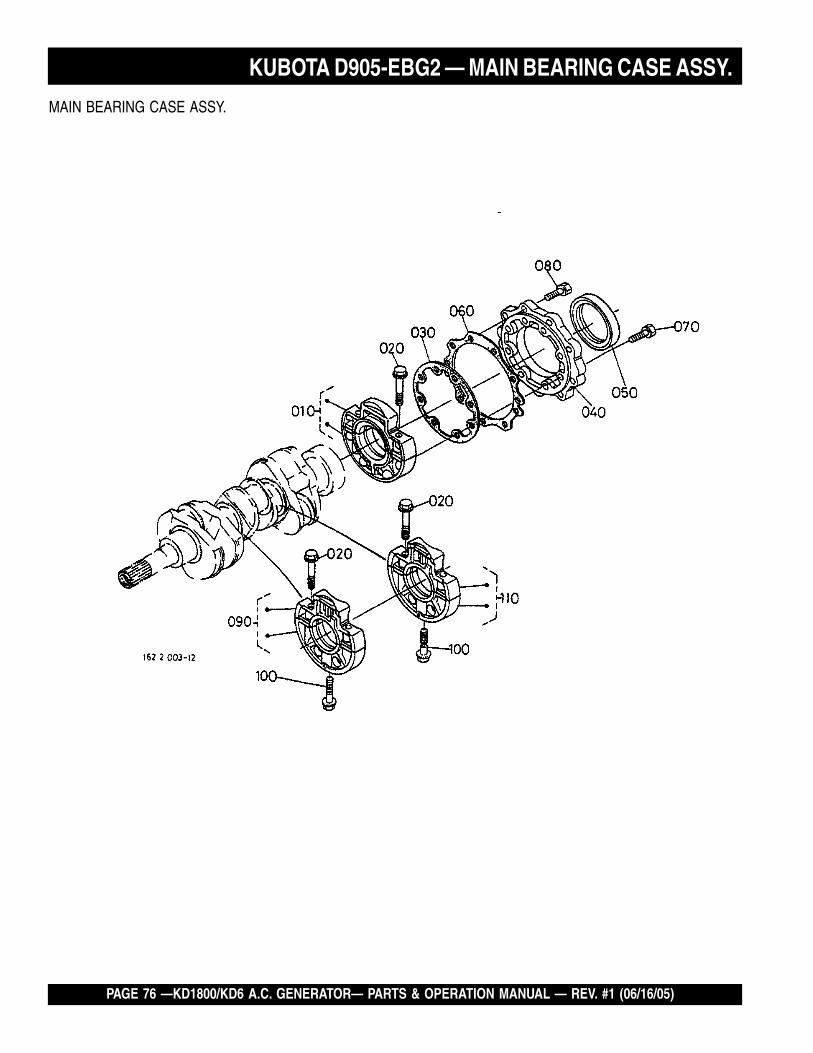
PAGE 76 —KD1800/KD6 A.C. GENERATOR— PARTS & OPERATION MANUAL — REV. #1 (06/16/05)
MAIN BEARING CASE ASSY.
KUBOTA D905-EBG2 — MAIN BEARING CASE ASSY.

KD1800/KD6 A.C. GENERATOR — PARTS & OPERATION MANUAL — REV. #1 (06/16/05) — PAGE 77
MAIN BEARING CASE ASSY.
NO. PART NO. PART NAME QTY. REMARKS010 1624104092 ASSEMBLY CASE, MAIN BRG. 1020 1624104540 BOLT, BEARING CASE 6030 1626404360 GASKET, BRG. CASE 1040 1624104813 COVER, BEARLING CASE 1050 1624104460 SEAL, OIL 1060 1626404820 GASKET 1070 0102350625 BOLT 8080 0102350620 BOLT 9090 1627104040 ASSEMBLY CASE, MAIN BRG. 1100 1624104560 BOLT, BEARING CASE 2110 1627104050 ASSEMBLY CASE, MAIN BRG. 1
KUBOTA D905-EBG2 — MAIN BEARING CASE ASSY.

PAGE 78 —KD1800/KD6 A.C. GENERATOR— PARTS & OPERATION MANUAL — REV. #1 (06/16/05)
CAMSHAFT AND IDLE GEAR SHAFT ASSY.
KUBOTA D905-EBG2 — CAMSHAFT AND IDLER GEAR SHAFT ASSY.

KD1800/KD6 A.C. GENERATOR — PARTS & OPERATION MANUAL — REV. #1 (06/16/05) — PAGE 79
CAMSHAFT AND IDLE GEAR SHAFT ASSY.
NO. PART NO. PART NAME QTY. REMARKS010 1626115550 TAPPET 6020 1624115110 PUSH ROD 6030 1626116010 ASSEMBLY CAMSHAFT 1040 1552193610 SCREW, SET 1050 1624116510 GEAR, CAM 1060 0571200518 KEY, FEATHER 1070 1624116270 STOPPER, CAMSHAFT 1080 0102350614 BOLT 2090 1627124010 COMPLETE GEAR, IDLE 1100 1627124980 BUSH, IDLE GEAR 1110 1624124360 COLLAR, IDLE GEAR 1120 1624124370 COLLAR, IDLE GEAR 1130 1624124320 CIR CLIP, IDLE GEAR 1140 1624124250 SHAFT, IDLE GEAR 1150 0102350616 BOLT 3
KUBOTA D905-EBG2 — CAMSHAFT AND IDLER GEAR SHAFT ASSY.

PAGE 80 —KD1800/KD6 A.C. GENERATOR— PARTS & OPERATION MANUAL — REV. #1 (06/16/05)
PISTON AND CRANKSHAFT ASSY.
KUBOTA D905-EBG2 — PISTON AND CRANKSHAFT ASSY.

KD1800/KD6 A.C. GENERATOR — PARTS & OPERATION MANUAL — REV. #1 (06/16/05) — PAGE 81
PISTON AND CRANKSHAFT ASSY.
NO. PART NO. PART NAME QTY. REMARKS010 1622421110 PISTON .....................................................3 .....................STD.010 1622421910 PISTON .....................................................3 ..................... +0. 50MM020 1590121050 ASSEMBLY PISTON RING ....................... 3 .....................STD.020 1590121090 ASSEMBLY PISTON RING ....................... 3 ..................... +0. 50MM030 1624121310 PIN, PISTON 3040 1624121330 CIR CLIP, PISTON PIN 6050 1624122012 ASSEMBLY ROD, CONNECTING 3060 1624121980 BUSH, PISTON PIN 3070 1624122140 BOLT, CONNECTING ROD 6080 1624122310 METAL, CRANKPIN .................................. 3 .....................STD. SET080 1624122970 METAL, CRANKPIN .................................. 3 ..................... - 0. 20MM SET080 1624122980 METAL, CRANKPIN .................................. 3 ..................... - 0. 40MM SET090 1623523013 COMPLETE CRANKSHAFT 1100 0771500401 BALL 3110 1624124110 GEAR, CRANK 1120 1627195230 KEY 1130 1624135630 GEAR, OIL PUMP DRIVE 1140 1624123280 SLEEVE, CRANKSHAFT 1150 1624123250 COLLAR, CRANKSHAFT 1160 0481410280 O RING 1170 1624123470 METAL, CRANKSHAFT .............................1 .....................STD.170 1624123910 METAL, CRANKSHAFT .............................1 ..................... - 0. 20MM170 1624123920 METAL, CRANKSHAFT .............................1 ..................... - 0. 40MM180 1624123480 METAL, CRANKSHAFT .............................2 .....................STD. SET180 1624123930 METAL, CRANKSHAFT .............................2 ..................... - 0. 20MM SET180 1624123940 METAL, CRANKSHAFT .............................2 ..................... - 0. 40MM SET190 1629223490 METAL, CRANKSHAFT .............................1 .....................STD. SET190 1624123860 METAL, CRANKSHAFT .............................1 ..................... - 0. 20MM SET190 1624123870 METAL, CRANKSHAFT .............................1 ..................... - 0. 40MM SET200 1552123530 METAL, SIDE ............................................ 2 .....................STD.200 1552123950 METAL, SIDE ............................................ 2 ..................... +0. 20MM200 1552123960 METAL, SIDE ............................................ 2 ..................... +0. 40MM210 1920223540 METAL, SIDE ............................................ 2 .....................STD.210 1920223970 METAL, SIDE ............................................ 2 ..................... +0. 20MM210 1920223980 METAL, SIDE ............................................ 2 ..................... +0. 40MM
KUBOTA D905-EBG2 — PISTON AND CRANKSHAFT ASSY.

PAGE 82 —KD1800/KD6 A.C. GENERATOR— PARTS & OPERATION MANUAL — REV. #1 (06/16/05)
FLYWHEEL ASSY.
KUBOTA D905-EBG2 — FLYWHEEL ASSY.

KD1800/KD6 A.C. GENERATOR — PARTS & OPERATION MANUAL — REV. #1 (06/16/05) — PAGE 83
FLYWHEEL ASSY.
NO. PART NO. PART NAME QTY. REMARKS010 1668325014 COMPLETE FLYWHEEL 1020 1626163820 GEAR, RING 1030 1624125160 BOLT, FLYWHEEL 6040 1668304610 HOUSING, FLYWHEEL 1050 1526191190 BOLT 8060 3122014170 COVER 1070 0112350814 BOLT 1080 0401350080 WASHER, PLAIN 1
KUBOTA D905-EBG2 — FLYWHEEL ASSY.

PAGE 84 —KD1800/KD6 A.C. GENERATOR— PARTS & OPERATION MANUAL — REV. #1 (06/16/05)
FUEL CAMSHAFT AND GOVERNOR SHAFT ASSY.
KUBOTA D905-EBG2 — FUEL CAMSHAFT AND GOVERNOR SHAFT ASSY.

KD1800/KD6 A.C. GENERATOR — PARTS & OPERATION MANUAL — REV. #1 (06/16/05) — PAGE 85
FUEL CAMSHAFT AND GOVERNOR SHAFT ASSY.
NO. PART NO. PART NAME QTY. REMARKS010 1602016170 CAMSHAFT, FUEL 1020 0810306202 BEARING, BALL 1030 0810306204 BEARING, BALL 1040 1627251150 GEAR, INJECTION PUMP 1050 1624151113 CAM, FUEL 1060 1624151190 WASHER 1070 1624192330 NUT, CAP 1080 1624195230 KEY, WOODRUFF 1090 0102350618 BOLT 3100 1624116320 STOPPER, FUEL. C/SHAFT 1110 0102350612 BOLT 2120 1668355010 ASSEMBLY SHAFT, GOVERNOR 1130 1668355310 SHAFT, GOVERNOR 1140 1669555390 HOLDER, GOVERNOR GEAR 1150 1668355320 GEAR, GOVERNOR 1160 1668355510 COLLAR, GOVERNOR WEIGHT 1170 1668355060 COMP. WEIGHT, GOVERNOR 2180 1981855340 WASHER 2190 1981855600 BEARING 2200 1668355260 WASHER, GOVERNOR WEIGHT 4210 1624155260 SHAFT, GOVERNOR WEIGHT 2220 1668355450 SLEEVE, GOVERNOR 1230 0810206304 BEARING, BALL 1240 1668355410 CIR- CLIP, GOVERNOR SHAFT 1250 1624155554 SCREW, SET 1
KUBOTA D905-EBG2 — FUEL CAMSHAFT AND GOVERNOR SHAFT ASSY.

PAGE 86 —KD1800/KD6 A.C. GENERATOR— PARTS & OPERATION MANUAL — REV. #1 (06/16/05)
KUBOTA D905-EBG2 — ENGINE STOP LEVER ASSY.
ENGINE STOP LEVER ASSY.

KD1800/KD6 A.C. GENERATOR — PARTS & OPERATION MANUAL — REV. #1 (06/16/05) — PAGE 87
ENGINE STOP LEVER ASSY.
NO. PART NO. PART NAME QTY. REMARKS010 1625954090 ASSEMBLY APPARATUS, IDLE 1020 1625954102 ASSEMBLY BOLT, ADJUSTING 1030 1584192020 NUT 1040 1584192330 NUT, CAP 1050 1560196650 GASKET 2060 1622154420 CAP 1070 1624154120 BOLT, ADJUSTING 1080 1G03154210 NUT, LOCK 1090 1584192330 NUT, CAP 1100 1560196650 GASKET 1110 BLANK120 1626483152 COVER, HYDRAULIC PUMP 1130 1G03196650 GASKET 1
KUBOTA D905-EBG2 — ENGINE STOP LEVER ASSY.

PAGE 88 —KD1800/KD6 A.C. GENERATOR— PARTS & OPERATION MANUAL — REV. #1 (06/16/05)
STOP SOLENOID ASSY.
KUBOTA D905-EBG2 — STOP SOLENOID ASSY.

KD1800/KD6 A.C. GENERATOR — PARTS & OPERATION MANUAL — REV. #1 (06/16/05) — PAGE 89
STOP SOLENOID ASSY.
NO. PART NO. PART NAME QTY. REMARKS010 1745460010 SOLENOID, STOP 1020 1629960150 GASKET 1030 0131110614 BOLT, HEX- SOC- HD 2040 0451250060 WASHER, SPRING 2
KUBOTA D905-EBG2 — STOP SOLENOID ASSY.

PAGE 90 —KD1800/KD6 A.C. GENERATOR— PARTS & OPERATION MANUAL — REV. #1 (06/16/05)
INJECTION PUMP ASSY.
KUBOTA D905-EBG2 — INJECTION PUMP ASSY.

KD1800/KD6 A.C. GENERATOR — PARTS & OPERATION MANUAL — REV. #1 (06/16/05) — PAGE 91
INJECTION PUMP ASSY.
NO. PART NO. PART NAME QTY. REMARKS010 1624195690 JOINT, EYE 1020 1603242010 ASSEMBLY TUBE, FUEL 1030 0966180075 TUBE, FUEL 1040 1491142750 CLIP, PIPE 2050 1603051010 ASSEMBLY PUMP, INJECTION 1060 1600652092 SHIM, INJECTION PUMP ......................... 1 ..................... 0. 20MM060 1600652112 SHIM, INJECTION PUMP ......................... 1 ..................... 0. 25MM070 1600652122 SHIM, INJECTION PUMP ......................... 1 ..................... 0. 30MM080 0131110620 BOLT, HEX- SOC- HD 2090 1584191500 STUD 2100 1584192320 NUT, CAP 2110 0451250060 WASHER, SPRING 4
KUBOTA D905-EBG2 — INJECTION PUMP ASSY.

PAGE 92 —KD1800/KD6 A.C. GENERATOR— PARTS & OPERATION MANUAL — REV. #1 (06/16/05)
INJECTION PUMP (COMPONENT PARTS) ASSY.
KUBOTA D905-EBG2 — INJECTION PUMP (COMPONENT PARTS) ASSY.

KD1800/KD6 A.C. GENERATOR — PARTS & OPERATION MANUAL — REV. #1 (06/16/05) — PAGE 93
INJECTION PUMP( COMPONENT PARTS) ASSY.
NO. PART NO. PART NAME QTY. REMARKS010 1603051010 ASSEMBLY PUMP, INJECTION 1020 1603051052 PLUNGER, PUMP 3030 1584151030 VALVE, DELIVERY 3040 1584151230 SPRING, DELIVERY VALVE 3050 1584151240 GASKET, DELIVERY VALVE 3060 1627151220 HOLDER, DELIVERY VALVE 3070 1584196760 O RING 3080 1584151560 FLANGE, SLEEVE 3090 1584194570 PIN, JOINT 3100 1584151200 O RING 6110 1586291430 SCREW 6120 1584151070 ASSEMBLY TAPPET 3130 1584151250 PIN, TAPPET GUIDE 3140 1586151430 PIN, CLAMP 1150 1584151280 SPRING, PLUNGER 3160 1584151270 SEAT, SPRING UPPER 3170 1584151290 SEAT, SPRING LOWER 3180 1584151490 SHIM 3190 1603051060 RACK, CONTROL 1200 1603051540 PLATE 1210 1584193110 SCREW, CSK- HD 4220 1584151380 SLEEVE, CONTROL 3230 1603051320 BOLT, JOINT 1240 1584196650 GASKET 2250 1584151350 SCREW 1260 1584196660 GASKET 1270 1603096010 PLUG 1280 1586196650 GASKET 1
KUBOTA D905-EBG2 — INJECTION PUMP (COMPONENT PARTS) ASSY.

PAGE 94 —KD1800/KD6 A.C. GENERATOR— PARTS & OPERATION MANUAL — REV. #1 (06/16/05)
GOVERNOR ASSY.
KUBOTA D905-EBG2 — GOVERNOR ASSY.

KD1800/KD6 A.C. GENERATOR — PARTS & OPERATION MANUAL — REV. #1 (06/16/05) — PAGE 95
GOVERNOR ASSY.
NO. PART NO. PART NAME QTY. REMARKS010 1626556480 SPRING, START 1020 1668456410 SPRING, GOVERNOR 1030 1668356052 ASSEMBLY LEVER, FORK 1040 1668356042 COMPLETE LEVER, FORK 1050 1981855600 BEARING 2060 1981855340 WASHER 2070 1668356130 LEVER, FORK 1080 1624156153 SHAFT, FORK LEVER 1090 1624194010 WASHER, PLAIN 1100 1624156330 BEARING, MINIATURIZE 1110 0461200090 CIR CLIP, EXTERNAL 1120 1624156250 COVER, FORK LEVER SHAFT 1130 1629956260 GASKET 1140 0102350614 BOLT 2150 1624156210 COLLAR 1160 1624156340 BEARING, MINIATURIZE 1
KUBOTA D905-EBG2 — GOVERNOR ASSY.

PAGE 96 —KD1800/KD6 A.C. GENERATOR— PARTS & OPERATION MANUAL — REV. #1 (06/16/05)
SPEED CONTROL PLATE ASSY.
KUBOTA D905-EBG2 — SPEED CONTROL PLATE ASSY.

KD1800/KD6 A.C. GENERATOR — PARTS & OPERATION MANUAL — REV. #1 (06/16/05) — PAGE 97
SPEED CONTROL PLATE ASSY.
NO. PART NO. PART NAME QTY. REMARKS010 1668357014 ASSEMBLY PLATE, CONTROL 1020 1627157150 LEVER, SPEED CONTROL 1030 1624157160 LEVER, SPEED CONTROL 1040 1668357162 LEVER, SPEED CONTROL 1050 0481400100 O RING 1060 0541100420 PIN, SPRING 2070 1624194020 WASHER, PLAIN 2080 1624192020 NUT 2090 1668356020 COMPLETE LEVER, GOVERNOR 1100 1627157720 LEVER, ENGINE STOP 1110 1547157980 SEAL, OIL 1120 1622257510 SPRING, RETURN 1130 1627157740 SHAFT, STOP LEVER 1140 1626457210 GASKET 1150 0102350616 BOLT 1160 0105350618 BOLT 1170 1560196650 GASKET 1180 1624591540 STUD 2190 0205650060 NUT 2200 0451250060 WASHER, SPRING 2
KUBOTA D905-EBG2 — SPEED CONTROL PLATE ASSY.

PAGE 98 —KD1800/KD6 A.C. GENERATOR— PARTS & OPERATION MANUAL — REV. #1 (06/16/05)
NOZZLE HOLDER AND GLOW PLUG ASSY.
KUBOTA D905-EBG2 — NOZZLE HOLDER AND GLOW PLUG ASSY.

KD1800/KD6 A.C. GENERATOR — PARTS & OPERATION MANUAL — REV. #1 (06/16/05) — PAGE 99
NOZZLE HOLDER AND GLOW PLUG ASSY.
NO. PART NO. PART NAME QTY. REMARKS010 1626142502 ASSEMBLY PIPE, OVER FLOW 1020 1584151360 SCREW, AIR BREEDER 1030 1560196650 GASKET 1040 1584142500 ASSEMBLY PIPE, OVER FLOW 1050 1497142750 CLIP, PIPE 2060 1603253000 ASSEMBLY HOLDER, NOZZLE 3070 1584153622 GASKET 3080 1907753650 SEAL, HEAT 3090 1627153712 PIPE, INJECTION 1100 1627153722 PIPE, INJECTION 1110 1627153732 PIPE, INJECTION 1120 1584153850 CLAMP, PIPE 2130 1584153860 CLAMP, PIPE 2140 0302450520 SCREW, WITH WASHER 2150 1685165510 GLOW PLUG 3160 1626165560 CORD, GLOW PLUG 1
KUBOTA D905-EBG2 — NOZZLE HOLDER AND GLOW PLUG ASSY.

PAGE 100 —KD1800/KD6 A.C. GENERATOR— PARTS & OPERATION MANUAL — REV. #1 (06/16/05)
NOZZLE HOLDER (COMPONENT PARTS) ASSY.
KUBOTA D905-EBG2 — NOZZLE HOLDER (COMPONENTS) ASSY.

KD1800/KD6 A.C. GENERATOR — PARTS & OPERATION MANUAL — REV. #1 (06/16/05) — PAGE 101
NOZZLE HOLDER (COMPONENT PARTS) ASSY.
NO. PART NO. PART NAME QTY. REMARKS010 1603253000 ASSEMBLY HOLDER, NOZZLE 3020 1603292030 NUT 3030 1603253230 WASHER, ADJUSTING 3040 1603253170 SPRING, NOZZLE 3050 1603253350 SPACER, DISTANCE 3060 1603253160 PUSH ROD 3070 1603253280 NUT, NOZZLE 3080 1603294040 WASHER, PLAIN 3090 1603253610 PIECE, NOZZLE 3100 1603298100 ASSEMBLY WASHER, ADJUST ...............3 .....................OPTION110 1603298500 WASHER, ADJUSTING .............................3 ..................... 0. 10MM110 1603298510 WASHER, ADJUSTING .............................3 ..................... 0. 20MM110 1603298520 WASHER, ADJUSTING .............................3 ..................... 0. 30MM110 1603298530 WASHER, ADJUSTING .............................3 ..................... 0. 40MM110 1603298540 WASHER, ADJUSTING .............................3 ..................... 0. 50MM110 1603298550 WASHER, ADJUSTING .............................3 ..................... 0. 52MM110 1603298560 WASHER, ADJUSTING .............................3 ..................... 0. 54MM110 16103298570 WASHER, ADJUSTING .............................3 ..................... 0. 56MM110 1603298580 WASHER, ADJUSTING .............................3 ..................... 0. 58MM110 1603298590 WASHER, ADJUSTING .............................3 ..................... 0.80MM
KUBOTA D905-EBG2 — NOZZLE HOLDER (COMPONENTS) ASSY.
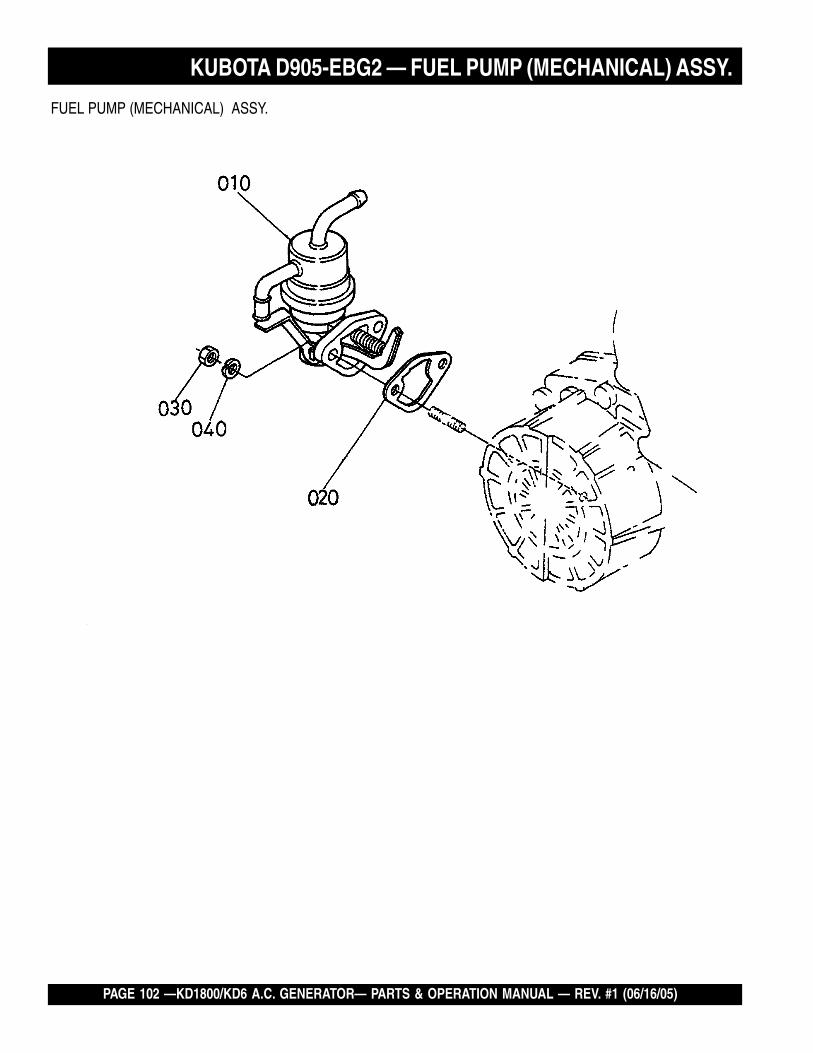
PAGE 102 —KD1800/KD6 A.C. GENERATOR— PARTS & OPERATION MANUAL — REV. #1 (06/16/05)
FUEL PUMP (MECHANICAL) ASSY.
KUBOTA D905-EBG2 — FUEL PUMP (MECHANICAL) ASSY.

KD1800/KD6 A.C. GENERATOR — PARTS & OPERATION MANUAL — REV. #1 (06/16/05) — PAGE 103
FUEL PUMP (MECHANICAL) ASSY.
NO. PART NO. PART NAME QTY. REMARKS010 1628552032 ASSEMBLY PUMP, FUEL 1020 1626452140 GASKET, FUEL PUMP 1030 0205650060 NUT 2040 0451250060 WASHER, SPRING 2
KUBOTA D905-EBG2 — FUEL PUMP (MECHANICAL) ASSY.

PAGE 104 —KD1800/KD6 A.C. GENERATOR— PARTS & OPERATION MANUAL — REV. #1 (06/16/05)
ALTERNATOR AND PULLEY ASSY.
KUBOTA D905-EBG2 — ALTERNATOR AND PULLEY ASSY.

KD1800/KD6 A.C. GENERATOR — PARTS & OPERATION MANUAL — REV. #1 (06/16/05) — PAGE 105
ALTERNATOR AND PULLEY ASSY.
NO. PART NO. PART NAME QTY. REMARKS010 1623164010 ASSEMBLY ALTERNATOR .......................1 ..................... 12V 30A020 1624164420 STAY, DYNAMO 1030 0112350830 BOLT 1040 0117351085 BOLT 1050 0401150100 WASHER, PLAIN 1060 0451250100 WASHER, SPRING 1070 0401550080 WASHER, PLAIN 1080 0102350616 BOLT 1090 1661613860 COVER, BELT 1100 1624174250 PULLEY, FAN 1110 1626174280 PULLEY, FAN DRIVE 1120 1624191020 BOLT, FAN DRIVE 1130 1491197010 V BELT ...................................................... 1 ..................... 37. 6IN140 1988365830 ASSEMBLY COUPLER 1150 1987265840 CONNECTOR 1160 1987265880 CONNECTOR 1170 1923765910 TERMINAL 7180 1926865780 ASSEMBLY TERMINAL 1190 6827165910 TERMINAL 1200 6827165920 SLEEVE 1210 1926865930 TERMINAL 1220 1926865870 SLEEVE 1230 1625965830 ASSEMBLY COUPLER, LOCK 1
KUBOTA D905-EBG2 — ALTERNATOR AND PULLEY ASSY.

PAGE 106 —KD1800/KD6 A.C. GENERATOR— PARTS & OPERATION MANUAL — REV. #1 (06/16/05)
ALTERNATOR (COMPONENT PARTS) ASSY.
KUBOTA D905-EBG2 — ALTERNATOR (COMPONENT PARTS) ASSY.

KD1800/KD6 A.C. GENERATOR — PARTS & OPERATION MANUAL — REV. #1 (06/16/05) — PAGE 107
ALTERNATOR (COMPONENT PARTS) ASSY.
NO. PART NO. PART NAME QTY. REMARKS010 1623164010 ASSEMBLY ALTERNATOR 1020 1588164110 PULLEY, DYNAMO 1030 1588192010 NUT 1040 1588164150 COLLAR 1050 1588164040 ROTOR 1060 1588164800 COVER, BEARING 1070 1588164770 BEARING, BALL 1080 1588164810 WASHER, THRUST 1090 1623164020 FRAME, DRIVE END 1100 1588164710 PLATE, RETAINER 1110 1588193010 SCREW, ROUND HEAD 4120 1588164260 BOLT, THROUGH 2130 1588164780 BEARING, BALL 1140 1624164060 FRAME, END 1150 1624164230 COVER, END 1160 1623164850 ASSEMBLY RECTIFIER 1170 1624164900 BUSH, INSULATION 1180 1588164310 HOLDER, BRUSH 1190 1588164090 BRUSH 2200 1588164330 SPRING, BRUSH 2210 1588193020 SCREW, ROUND HEAD 2220 1588193030 SCREW, ROUND HEAD 6230 1588193040 SCREW, ROUND HEAD 1240 1588191040 BOLT 3250 1588192020 NUT 2260 1588191050 BOLT 2270 1418292030 NUT 1280 1588164600 ASSEMBLY REGULATOR 1
KUBOTA D905-EBG2 — ALTERNATOR (COMPONENT PARTS) ASSY.

PAGE 108 —KD1800/KD6 A.C. GENERATOR— PARTS & OPERATION MANUAL — REV. #1 (06/16/05)
STARTER ASSY.
KUBOTA D905-EBG2 — STARTER ASSY.

KD1800/KD6 A.C. GENERATOR — PARTS & OPERATION MANUAL — REV. #1 (06/16/05) — PAGE 109
STARTER ASSY.
NO. PART NO. PART NAME QTY. REMARKS010 1661263010 ASSEMBLY STARTER ............................. 1 ..................... 12V 1. OKW020 0112350830 BOLT 2
KUBOTA D905-EBG2 — STARTER ASSY.

PAGE 110 —KD1800/KD6 A.C. GENERATOR— PARTS & OPERATION MANUAL — REV. #1 (06/16/05)
STARTER (COMPONENT PARTS) ASSY.
KUBOTA D905-EBG2 — STARTER (COMPONENT PARTS) ASSY.

KD1800/KD6 A.C. GENERATOR — PARTS & OPERATION MANUAL — REV. #1 (06/16/05) — PAGE 111
STARTER (COMPONENT PARTS) ASSY.
NO. PART NO. PART NAME QTY. REMARKS010 1651263010 ASSEMBLY STARTER 1020 1661263080 ASSEMBLY YOKE 1030 1550163370 BRUSH 2040 1550163070 ARMATURE 1050 1550463500 BEARING, BALL 1060 1550463530 BEARING BALL 1070 1550463040 CLUTCH 1080 1550463030 HOUSING 1090 1661263020 ASSEMBLY SWITCH, MAGNETIC 1100 1550163380 HOLDER, BRUSH 1110 1540163390 SPRING, BRUSH 4120 1627163200 FRAME, END 1130 1123363280 GEAR 1140 1921263100 ROLLER 5150 1921263110 RETAINER 1160 1921297130 BALL 1170 1921263120 SPRING 1180 1550196670 WASHER, FELT 1190 1550193310 SCREW, PAN- HEAD 2200 1550163320 BOLT, THROUGH 2210 1550191020 BOLT 2220 6795559230 NUT 1230 6795559240 COVER 1240 1661163660 CORD, STOP SOLENOID 1250 1661263100 BAND, COVER 1
KUBOTA D905-EBG2 — STARTER (COMPONENT PARTS) ASSY.

PAGE 112 —KD1800/KD6 A.C. GENERATOR— PARTS & OPERATION MANUAL — REV. #1 (06/16/05)
OIL SWITCH/ THERMOMETER AND PLUG ASSY.
KUBOTA D905-EBG2 — OIL SWITCH/THERMOMETER AND PLUG ASSY.

KD1800/KD6 A.C. GENERATOR — PARTS & OPERATION MANUAL — REV. #1 (06/16/05) — PAGE 113
OIL SWITCH/ THERMOMETER AND PLUG ASSY.
NO. PART NO. PART NAME QTY. REMARKS010 SWITCH, OIL ............................................ 1 .....................SEE PAGE 49, ITEM 20020 1584196020 PLUG 1
KUBOTA D905-EBG2 — OIL SWITCH/THERMOMETER AND PLUG ASSY.

PAGE 114 —KD1800/KD6 A.C. GENERATOR— PARTS & OPERATION MANUAL — REV. #1 (06/16/05)
WATER FLANGE AND THERMOSTAT ASSY.
KUBOTA D905-EBG2 — WATER FLANGE AND THERMOSTAT ASSY.

KD1800/KD6 A.C. GENERATOR — PARTS & OPERATION MANUAL — REV. #1 (06/16/05) — PAGE 115
WATER FLANGE AND THERMOSTAT ASSY.
NO. PART NO. PART NAME QTY. REMARKS010 1661372700 COMPLETE FLANGE, WATER 1020 1624173370 PIPE, WATER RETURN 1030 1929896020 PLUG 2040 1626472920 GASKET, WATER FLANGE 1050 0102350616 BOLT 3060 0102350655 BOLT 1070 1624173350 PIPE, WATER RETURN 1080 1624173360 BAND, PIPE 2090 1943473010 ASSEMBLY THERMOSTAT 1100 1621973260 COVER, THERMOSTAT 1110 1531373270 GASKET, THERMOSTAT 1120 0112350835 BOLT 2
KUBOTA D905-EBG2 — WATER FLANGE AND THERMOSTAT ASSY.

PAGE 116 —KD1800/KD6 A.C. GENERATOR— PARTS & OPERATION MANUAL — REV. #1 (06/16/05)
WATER PUMP ASSY.
KUBOTA D905-EBG2 — WATER PUMP ASSY.

KD1800/KD6 A.C. GENERATOR — PARTS & OPERATION MANUAL — REV. #1 (06/16/05) — PAGE 117
WATER PUMP ASSY.
NO. PART NO. PART NAME QTY. REMARKS010 1625973032 ASSEMBLY PUMP, WATER 1020 1625973520 FLANGE, WATER PUMP 1030 1625973550 BEARING 1040 1548173050 ASSEMBLY SEAL, MECHANICAL 1050 1625973510 IMPELLER, WATER PUMP 1060 1624173340 PIPE, WATER RETURN 1070 1623973430 GASKET, WATER PUMP 1080 0102350630 BOLT 4090 0102350680 BOLT 2
KUBOTA D905-EBG2 — WATER PUMP ASSY.

PAGE 118 —KD1800/KD6 A.C. GENERATOR— PARTS & OPERATION MANUAL — REV. #1 (06/16/05)
WATER PIPE ASSY.
KUBOTA D905-EBG2 — WATER PIPE ASSY.

KD1800/KD6 A.C. GENERATOR — PARTS & OPERATION MANUAL — REV. #1 (06/16/05) — PAGE 119
WATER PIPE ASSY.
NO. PART NO. PART NAME QTY. REMARKS010 1628572860 PIPE, WATER 1020 1624172870 PIPE, WATER 1030 3620082720 CLAMP 2
KUBOTA D905-EBG2 — WATER PIPE ASSY.

PAGE 120 —KD1800/KD6 A.C. GENERATOR— PARTS & OPERATION MANUAL — REV. #1 (06/16/05)
FAN ASSY.
KUBOTA D905-EBG2 — FAN ASSY.

KD1800/KD6 A.C. GENERATOR — PARTS & OPERATION MANUAL — REV. #1 (06/16/05) — PAGE 121
FAN ASSY.
NO. PART NO. PART NAME QTY. REMARKS010 1554774112 FAN 1020 0175450620 BOLT, FLANGE 4030 1587674150 COLLAR, FAN 1
KUBOTA D905-EBG2 — FAN ASSY.

PAGE 122 —KD1800/KD6 A.C. GENERATOR— PARTS & OPERATION MANUAL — REV. #1 (06/16/05)
VALVE AND ROCKER ARM ASSY.
KUBOTA D905-EBG2 — VALVE AND ROCKER ARM ASSY.

KD1800/KD6 A.C. GENERATOR — PARTS & OPERATION MANUAL — REV. #1 (06/16/05) — PAGE 123
VALVE AND ROCKER ARM ASSY.
NO. PART NO. PART NAME QTY. REMARKS010 1624113110 VALVE, INLET 3020 0624113120 VALVE, EXHAUST 3030 1627113240 SPRING, VALVE 6040 1624113330 RETAINER, VALVE SP. 6050 1526113360 COLLET, VALVE SPRING .........................6 .....................SET060 1C01013150 SEAL, VALVE STEM 6070 1624113280 CAP, VALVE 6080 1626114264 SHAFT, ROCKER ARM 1090 0102350610 BOLT 2100 1624114350 BRACKET, ROCKER ARM 3110 0541100428 PIN, SPRING 1120 1624114430 WASHER, R- ARM. SHAFT 2130 1584194022 WASHER, PLAIN 2140 1624114319 SPRING, ROCKER ARM 2160 1624114032 ASSEMBLY ROCKER ARM 6170 1624114230 SCREW, ADJUSTING 6180 1624114240 NUT 6190 1624114410 STUD 3200 1526192010 NUT 3210 1526194010 WASHER, PLAIN 3
KUBOTA D905-EBG2 — VALVE AND ROCKER ARM ASSY.
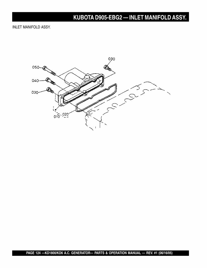
PAGE 124 —KD1800/KD6 A.C. GENERATOR— PARTS & OPERATION MANUAL — REV. #1 (06/16/05)
INLET MANIFOLD ASSY.
KUBOTA D905-EBG2 — INLET MANIFOLD ASSY.

KD1800/KD6 A.C. GENERATOR — PARTS & OPERATION MANUAL — REV. #1 (06/16/05) — PAGE 125
INLET MANIFOLD ASSY.
NO. PART NO. PART NAME QTY. REMARKS010 1626111770 ASSEMBLY MANIFOLD, INLET 1020 1626111822 GASKET, IN- MANIFOLD 1030 0102350618 BOLT 3040 0102350630 BOLT 1050 0102360650 BOLT 2
KUBOTA D905-EBG2 — INLET MANIFOLD ASSY.

PAGE 126 —KD1800/KD6 A.C. GENERATOR— PARTS & OPERATION MANUAL — REV. #1 (06/16/05)
EXHAUST MANIFOLD ASSY.
KUBOTA D905-EBG2 — EXHAUST MANIFOLD ASSY.

KD1800/KD6 A.C. GENERATOR — PARTS & OPERATION MANUAL — REV. #1 (06/16/05) — PAGE 127
EXHAUST MANIFOLD ASSY.
NO. PART NO. PART NAME QTY. REMARKS010 1721312312 MANIFOLD, EXHAUST 1020 1626112350 GASKET, EX- MANIFOLD 1030 1624191490 STUD 6040 1627192010 NUT 6
KUBOTA D905-EBG2 — EXHAUST MANIFOLD ASSY.

PAGE 128 —KD1800/KD6 A.C. GENERATOR— PARTS & OPERATION MANUAL — REV. #1 (06/16/05)
ACCESSORIES AND SERVICE PARTS ASSY.
KUBOTA D905-EBG2 — ACCESSORIES AND SERVICE PARTS ASSY.

KD1800/KD6 A.C. GENERATOR — PARTS & OPERATION MANUAL — REV. #1 (06/16/05) — PAGE 129
ACCESSORIES AND SERVICE PARTS ASSY.
NO. PART NO. PART NAME QTY. REMARKS010 1526312370 GASKET, MUFFLER NA 1020 0112350822 BOLT 4
KUBOTA D905-EBG2 — ACCESSORIES AND SERVICE PARTS ASSY.
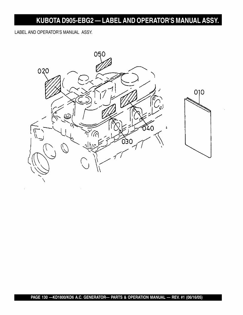
PAGE 130 —KD1800/KD6 A.C. GENERATOR— PARTS & OPERATION MANUAL — REV. #1 (06/16/05)
LABEL AND OPERATOR’S MANUAL ASSY.
KUBOTA D905-EBG2 — LABEL AND OPERATOR'S MANUAL ASSY.

KD1800/KD6 A.C. GENERATOR — PARTS & OPERATION MANUAL — REV. #1 (06/16/05) — PAGE 131
LABEL AND OPERATOR’S MANUAL ASSY.
NO. PART NO. PART NAME QTY. REMARKS010 1668389166 MANUAL, INSTRUCTION 1020 1622587114 NAME PLATE, ENGINE 1030 1942687903 LABEL 1040 1942687880 LABEL, INSTRUCTION 1050 1668388690 LABEL 1
KUBOTA D905-EBG2 — LABEL AND OPERATOR'S MANUAL ASSY.

PAGE 132 —KD1800/KD6 A.C. GENERATOR— PARTS & OPERATION MANUAL — REV. #1 (06/16/05)
PAYMENT TERMS
Terms of payment for parts are net 10 days.
FREIGHT POLICY
All parts orders will be shipped collect orprepaid with the charges added to the invoice.All shipments are F.O.B. point of origin.Multiquip’s responsibility ceases when a signedmanifest has been obtained from the carrier,and any claim for shortage or damage must besettled between the consignee and the carrier.
MINIMUM ORDER
The minimum charge for orders from Multiquipis $15.00 net. Customers will be asked forinstructions regarding handling of orders notmeeting this requirement.
RETURNED GOODS POLICY
Return shipments will be accepted and creditwill be allowed, subject to the followingprovisions:
1. A Returned Material Authorization mustbe approved by Multiquip prior to shipment.
2. To obtain a Return Material Authorization,a list must be provided to Multiquip PartsSales that defines item numbers,quantities, and descriptions of the items tobe returned.
a. The parts numbers and descriptionsmust match the current parts pricelist.
b. The list must be typed or computergenerated.
c. The list must state the reason(s) forthe return.
d. The list must reference the salesorder(s) or invoice(s) under whichthe items were originally purchased.
e. The list must include the name andphone number of the personrequesting the RMA.
3. A copy of the Return MaterialAuthorization must accompany the returnshipment.
PRICING AND REBATES
Prices are subject to change without priornotice. Price changes are effective on a specificdate and all orders received on or after that datewill be billed at the revised price. Rebates forprice declines and added charges for priceincreases will not be made for stock on hand atthe time of any price change.
Multiquip reserves the right to quote and selldirect to Government agencies, and to OriginalEquipment Manufacturer accounts who useour products as integral parts of their ownproducts.
SPECIAL EXPEDITING SERVICE
A $20.00 to $50.00 surcharge will be added tothe invoice for special handling including busshipments, insured parcel post or in caseswhere Multiquip must personally deliver theparts to the carrier.
LIMITATIONS OF SELLER’S LIABILITY
Multiquip shall not be liable here under fordamages in excess of the purchase price of theitem with respect to which damages are claimed,and in no event shall Multiquip be liable for lossof profit or good will or for any other special,consequential or incidental damages.
LIMITATION OF WARRANTIES
No warranties, express or implied, are made inconnection with the sale of parts or tradeaccessories nor as to any engine notmanufactured by Multiquip. Such warrantiesmade in connection with the sale of new,complete units are made exclusively by astatement of warranty packaged with suchunits, and Multiquip neither assumes notauthorizes any person to assume for it anyother obligation or liability whatever inconnection with the sale of its products. A partfrom such written statement of warranty, thereare no warranties, express, implied or statutory,which extend beyond the description of theproducts on the face hereof.
4. Freight is at the sender’s expense. Allparts must be returned freight prepaid toMultiquip’s designated receiving point.
5. Parts must be in new and resalablecondition, in the original Multiquip package(if any), and with Muiltiquip part numbersclearly marked.
6. The following items are not returnable:
a. Obsolete parts. (If an item is listedin the parts price book as beingreplaced by another item, it isobsolete.)
b. Any parts with a limited shelf life(such as gaskets, seals, “O” rings,and other rubber parts) that werepurchased more than six monthsprior to the return date.
c. Any line item with an extended dealernet price of less than $5.00.
d. Special order items.
e. Electrical components.
f. Paint, chemicals, and lubricants.
g. Decals and paper products.
h. Items purchased in kits.
7. The sender will be notified of any materialreceived that is not acceptable.
8. Such material will be held for 5 workingdays from notification, pendinginstructions. If a reply is not receivedwithin 5 days, the material will be returnedto the sender at his expense.
9. Credit on returned parts will be issued atdealer net price at time of the originalpurchase, less a 15% restocking charge.
10. In cases where an item is accepted forwhich the original purchase documentcan not be determined, the price will bebased on the list price that was effectivetwelve months prior to the RMA date.
11. Credit issued will be applied to futurepurchases only.
Effective: July 1, 2000 TERMS AND CONDITIONS OF SALE — PARTS

KD1800/KD6 A.C. GENERATOR — PARTS & OPERATION MANUAL — REV. #1 (06/16/05) — PAGE 133
NOTE PAGE

PARTS AND OPERATION MANUAL
MULTIQUIP INC.POST OFFICE BOX 6254CARSON, CA 90749310-537-3700 • 800-421-1244FAX: 310-537-3927E-MAIL: [email protected]: multiquip.com
Atlanta • Boise • Dallas • Houston • NewarkQuebec, Canada • Manchester, UK • Rio De Janiero, BR • Guadalajara, MX
HERE'S HOW TO GET HELPPLEASE HAVE THE MODEL AND SERIAL NUMBERON-HAND WHEN CALLING
PARTS DEPARTMENT800-427-1244 or 310-537-3700FAX: 800-672-7877 or 310-637-3284
SERVICE DEPARTMENT/TECHNICAL ASSISTANCE800-478-1244 or 310-537-3700FAX: 310- 537-4259
WARRANTY DEPARTMENT888-661-4279, or 310-661-4279FAX: 310- 537-1173
MAIN800-421-1244 or 310-537-3700FAX: 310-537-3927