k.balaji 𝐌𝐄 𝐜 )..,
TRANSCRIPT

WWWVIDYARTHIPLUSCOM
WWWVIDYARTHIPLUSCOM KBALAJI 119820119812 (119852119853119851119854119836119853)
ST7016 Prefabricated Structures
JAYAM COLLEGE OF ENGINEERING AND
TECHNOLOGY DHARMAPURI TAMILNADU
KBALAJI 119820119812 (119852119853119851119854119836119853)
WWWVIDYARTHIPLUSCOM
WWWVIDYARTHIPLUSCOM KBALAJI 119820119812 (119852119853119851119854119836119853)
Unit-1
Design principles
Prefabrication is the practice of assembling components of a structure in
a factory or other manufacturing site and transporting complete assemblies or sub-
assemblies to the construction site where the structure is to be located The term is used
to distinguish this process from the more conventional construction practice of
transporting the basic materials to the construction site where all assembly is carried out
Prefabrication is one of the architectural constructions Large units of a building are
produced in factories to be assembled ready-made on the building site This technique
permits the speedy erection of very large structures Units may include doors stairs
windows wall panels floor panels roof trusses and even entire buildings
Prefabricated building
Prefabricated building is a type of building that consists of several factory-built
components or units that are assembled on-site to complete the unit
The term prefabricated is buildings built in components (eg panels) modules (modular
homes) transportable sections (manufactured homes)It may also be used to refer to
mobile homes
Different Between Prefabricated Constructions and Conventional Type
The conventional method of building a house is to transport bricks timber
cement sand and construction aggregate etc to the site and to construct the house on
site from these materials In prefabricated construction only the foundations and floor
slabs are constructed in this way while sections of walls and roof are prefabricated
WWWVIDYARTHIPLUSCOM
WWWVIDYARTHIPLUSCOM KBALAJI 119820119812 (119852119853119851119854119836119853)
(assembled) in a factory (possibly with window and door frames included) transported to
the site lifted into place by a crane and bolted together
Need for Prefabrication
Cost of construction
shorter construction time
easy of expansion
utilization of material
attractive finishes
highly efficient for weather resistance
single source assurance
insurance advantage
Material Properties In of Prefabricated Structures
Quick to assemble
Cost-effective
Portablemovable
Strong
Waterproof Moisture proof
Fire Resistant
Prefabrication Types
1 Conventional prefabrication construction is the most traditional construction
method where all the construction activities are in-situ practices on site
2 Semi-prefabrication divides as two sub-categories system formwork and non-
structural semi-prefabrication involving a part of in-situ construction activities
and a part of prefabrication Normally the non-structural semi-prefabrication is
applied on faccedilade curtain walls lost form systems and dry wall systems
WWWVIDYARTHIPLUSCOM
WWWVIDYARTHIPLUSCOM KBALAJI 119820119812 (119852119853119851119854119836119853)
3 Comprehensive prefabrication involves a structural part and pre-finished
construction Examples of applications of structural comprehensive prefabrication
include staircases slabs columns and beams and
4 Volumetric off-site fabrication encloses usable space but does not constitute the
whole building Volumetric off-site fabrication is mainly used for lsquofacilitiesrsquo and
includes solutions on office washrooms plant rooms building services risers and
lifts
ADVANTAGES OF PREFABRICATION
1 Self-supporting ready-made components are used so the need for formwork
shuttering and scaffolding is greatly reduced
2 Construction time is reduced and buildings are completed sooner allowing an
earlier return of the capital invested
3 Quality control can be easier in a factory assembly line setting than a construction
site setting
4 Prefabrication can be located where skilled labour is more readily available and
costs of labour power materials space and overheads are lower
5 Time spent in bad weather or hazardous environments at the construction site is
minimized
6 Less waste may be generated and in a factory setting it may be easier to recycle it
back into the manufacturing process for instance it is less costly to recycle scrap
metal generated in a metal fabrication shop than on the construction site
7 On-site construction and congestion is minimized
DISADVANTAGES OF PREFABRICATION
1 Careful handling of prefabricated components such as concrete panels or steel and
glass panels is required
2 Attention has to be paid to the strength and corrosion-resistance of the joining of
prefabricated sections to avoid failure of the joint
3 Similarly leaks can form at joints in prefabricated components
WWWVIDYARTHIPLUSCOM
WWWVIDYARTHIPLUSCOM KBALAJI 119820119812 (119852119853119851119854119836119853)
4 Transportation costs may be higher for voluminous prefabricated sections than for
the materials of which they are made which can often be packed more compactly
5 Large prefabricated sections require heavy-duty cranes and precision measurement
and handling to place in position
6 Modular coordination
7 Modular coordination or MC is a dimensional system It is a dimension and space
coordination concept in which building and components are placed at their
designations based on the unit or basic module known as 1M that equals to 100
mm The use of MC is an important factor in IBS effective application as it
completes the industry through quality control and increase of productivity
WWWVIDYARTHIPLUSCOM
WWWVIDYARTHIPLUSCOM KBALAJI 119820119812 (119852119853119851119854119836119853)
MODULAR HOMES
Modular homes are houses divided into multiple modules sections which are
manufactured in a remote facility and then delivered to their intended site of use The
modules are assembled into a single residential building using either a crane or trucks
Steel andor wood framing are common options for building a modular homes Modular
components are typically constructed within a large indoor facility on assembly lines
WWWVIDYARTHIPLUSCOM
WWWVIDYARTHIPLUSCOM KBALAJI 119820119812 (119852119853119851119854119836119853)
Modular homes
Indoor Construction of modular homes
Such dwellings are often priced lower than their site-built counterparts and are typically
more cost-effective to builders and consumers These new homes can be constructed in
less time than it takes to build a home on-siteldquo
Importance of modular homes
1 Indoor construction Assembly is independent of weather which increases work
efficiency and avoids damaged building material
WWWVIDYARTHIPLUSCOM
WWWVIDYARTHIPLUSCOM KBALAJI 119820119812 (119852119853119851119854119836119853)
2 Favourable pricing from suppliers Large-scale manufacturers can effectively
bargain with suppliers for discounts on materials
3 Ability to service remote locations Particularly in countries such as Australia
there can be much higher costs to build a site-built house in a remote area or an
area experiencing a construction boom such as mining towns Modular homes can
be built in major towns and sold to regional areas
4 Low waste With the same plans being constantly built the manufacturer has
records of exactly what quantity of materials is needed for a given job While
waste from a site-built dwelling may typically fill several large dumpsters waste
from a modular dwelling generates much less waste
5 Building Strength According to manufacturers modular homes are generally
designed to be initially stronger than traditional homesFor example replacing
nails with screws and adding glue to joints This is supposed to help the modules
maintain their structural integrity as they are transported on trucks to the
construction site
6 Assembly Time The modules that will combine to form the house are assembled
off-site in a factory These modules can take one to three months to be constructed
but often take as little as 10 days to actually construct when they are first started
Then they are transported to the building site where a crane is brought in to
assemble the modules togetherThe placement of the modules together generally
takes several hours or days
Mobile Homes
Mobile homes or static caravans are prefabricated homes built in factories rather than on
site and then taken to the place where they will be occupied They are usually
transported by tractor-trailers over public roads to sites which are often in rural areas or
high-density developments In some countries they are used for temporary
WWWVIDYARTHIPLUSCOM
WWWVIDYARTHIPLUSCOM KBALAJI 119820119812 (119852119853119851119854119836119853)
accommodation on campsites While these houses are usually placed in one location and
left there permanently or they have the ability to be move
Behind the work fitted at installation to hide the base there are strong trailer frames
axles wheels and tow-hitches The two major sizes are single-wides and double-wides
1 Single-wides are eighteen feet or less in width and 90 feet (27 m) or less in length
and can be towed to their site as a single unit
Double-wides are twenty feet or more wide and are 90 feet (27 m) in length or less and
are towed to their site in two separate units which are then joined together
WWWVIDYARTHIPLUSCOM
WWWVIDYARTHIPLUSCOM KBALAJI 119820119812 (119852119853119851119854119836119853)
Mobile homes
Production Transportation and Erection
Considerations in production
The general rule is that the connection device must be as lsquofoolproofrsquo as possible It
should be possible to place it in the mould correctly oriented and within the necessary
tolerances with a minimum of effort
1 Avoid congestion
At the location of connections additional reinforcing steel embedded plates
inserts block-outs etc are frequently required It is not unusual that so many items are
concentrated in a small location that very little room is left for the concrete It must be
kept in mind that reinforcing bars and prestressing strands which appear as lines on the
drawing take up real space in the elements Reinforcing bars require more space than
their nominal diameter and there must be room for the curvature of bent bars If
congestion is suspected it is helpful to draw large-scale details of the region in question
2 Avoid penetration of the forms
Units requiring holes in the forms should be avoided if possible especially in steel
moulds Exceptions to this rule can be made if there is a substantial amount of repetition
in the production Holes in the forms may be necessary not only because the units are
WWWVIDYARTHIPLUSCOM
WWWVIDYARTHIPLUSCOM KBALAJI 119820119812 (119852119853119851119854119836119853)
protruding from the elements but also for the arrangement used to keep the units in place
during casting The units must also be designed so that they do not make the dismantling
of the form impossible without damage to the form Most forms are supposed to be used
more than once Connection units to be placed in the top surface during casting should be
secured against the edges of the mould using purpose made holding devices These
devices are mostly costly make it more difficult to obtain a smooth surface or the
holding device may hamper the placement of concrete or other surface material The
various disadvantages have to be evaluated before selecting the method However if the
same steel plate is placed in the bottom of the form it can be located with great accuracy
as it can be fixed to the bottom directly
3 Reduce post-stripping work
A plant casting operation is most efficient when the product can be taken directly
to the storage area immediately after removal from the form Any operations required
after stripping and before erection such as special cleaning or finishing welding on
projecting hardware etc should be avoided These operations require additional handling
(increased possibility of damage to the elements) extra workspace and added labour
often with skilled trades Sometimes a trade-off is necessary between penetration of the
forms and post-stripping work
4 Use repetitious details
It is very desirable to repeat details as much as possible Similar details should be
identical even ifit results in a slight over-design
5 Use standard items
Hardware items such as inserts studs steel elements etc should be readily
available standard items that are preferably from more than one supplier It also
simplifies fabrication if similar product items are standardised as to size and shape There
is also less chance of error The same principle applies to reinforcing bars embedded
plates etc
WWWVIDYARTHIPLUSCOM
WWWVIDYARTHIPLUSCOM KBALAJI 119820119812 (119852119853119851119854119836119853)
6 Be aware of material limitations
Examples of this are the radius requirements for bending reinforcing bars standard
lengths for
certain sizes of inserts etc
7 Avoid non-standard tolerances
Dimensional tolerances which are specified to be more rigid than industry
standards are difficult to achieve Connections which require close-fitting parts without
provision for adjustment should be avoided as much as possible
8 Allow alternatives
Very often precasters will prefer certain details The producer should be allowed
to use alternative methods or materials provided the design requirements are met
Allowing alternative solutions willoften result in the most economical and best
performing connections
Considerations for transportation
During transportation any units protruding from the concrete element must be
shielded in order not to create a hazard to people Protruding units must be able to
withstand any shocks they can be subjected to during handling Protruding units like
reinforcing bars can in many cases be difficult to handle during transportation For
example a wall panel shall be transported standing at the edge but has reinforcing bars
protruding at the bottom This will make it necessary to build up the support on the
trucks which is costly takes time and makes the load less stable This problem can be
solved by letting the bars protrude from the top of the element but then the total height
may make it difficult to negotiate the underpasses en route The solution may then be to
have the protruding bars replaced by insert and threaded bar to screw in after the element
has been transported to the site
WWWVIDYARTHIPLUSCOM
WWWVIDYARTHIPLUSCOM KBALAJI 119820119812 (119852119853119851119854119836119853)
If protruding units do not create the kind of problems described above because
they do not stick out that much there still may be some difficulties For example corbels
pointing down during transport may necessitate a lot of additional support provisions for
the columns on the trucks The consequence can be a less stable load or decreased
loading capacity of the truck This kind of problem can be solved by making columns
with the corbels in one plane only and then place every second column lsquotop-to-bottomrsquo
on the trucks Otherwise it is also possible to look for a corbel-free solution
Considerations for Erection
To fully realise this benefit of fast erection of a precast structure and to keep the
costs within reasonable limits field connections should be kept simple In order to fulfil
the design requirements it is sometimes necessary to compromise fabrication and
erection simplicity
1 Use connections that are not weather sensitive
Materials such as grout dry pack cast-in-place concrete and epoxies need special
provisions to be placed in cold weather Welding is slower when the ambient temperature
is low If the connections are designed so that these processes must be completed before
erection can continue costly delays may result
2 Stability of the elements
Some elements may require propping shoring bracing or fastening before the
hoist can be unhooked Planning for the fewest quickest and safest possible operations to
be executed before releasing the hoist will greatly facilitate the erection
WWWVIDYARTHIPLUSCOM
WWWVIDYARTHIPLUSCOM KBALAJI 119820119812 (119852119853119851119854119836119853)
3 Stability of the structure
In every stage of the erection process the stability of the structure as a whole must
be planned and assured If not costly additional measures may have to be taken The
type of connection used may play a decisive role in this
4 Be aware of possible different loading conditions during erection
During erection loading conditions can occur which induce stresses or
deformations as well in the precast concrete units as in the connections which are higher
than those under service conditions When designing the connections due consideration
has to be paid to these effects unless special measures are taken during the erection such
as temporary supports etc to prevent such situations
5 Standardize connection types
All connections which serve similar functions within the building should be
standardized as much as possible As workmen become familiar with the procedures
required to make the connection productivity is enhanced and there is less chance for
error
Some types of connections require skilled craftsmen to accomplish for example
welding and post tensioning The fewer of these skilled trades required the more
economical the connection will be
6 Standardize sizes of components
Whenever possible such things as field bolts loose angles etc should be of
common size for all connections This reduces the chance for error and the time required
searching for the proper item
WWWVIDYARTHIPLUSCOM
WWWVIDYARTHIPLUSCOM KBALAJI 119820119812 (119852119853119851119854119836119853)
7 Use connections that are not susceptible to damage in handling
Reinforcing bars steel plates dowels and bolts that project from the precast piece
will often be damaged in handling requiring repair to make them fit especially if they
are of small diameter or thickness
Connection detail that makes erection impossible
Support solution that makes erection impossible
SHEAR WALL
Shear walls are vertical elements of the horizontal force resisting system Shear walls are
constructed to counter the effects of lateral load acting on a structure In residential
construction shear walls are straight external walls that typically form a box which
provides all of the lateral support for the building
Importance of shear wall
WWWVIDYARTHIPLUSCOM
WWWVIDYARTHIPLUSCOM KBALAJI 119820119812 (119852119853119851119854119836119853)
When shear walls are designed and constructed property and they will have the strength
and stiffness to resist the horizontal forces In building construction a rigid vertical
diaphragm capable of transferring lateral forces from exterior walls floors and roofs to
the ground foundation in a direction parallel to their planes Lateral forces caused by
wind earthquake and uneven settlement loads In addition to the weight of structure and
occupants create powerful twisting (torsion) forces These forces can literally tear (shear)
a building apart Reinforcing a frame by attaching or placing a rigid wall inside it
maintains that shape of the frame and prevents rotation at the joints shear walls are
especially important in high-rise building subjected to lateral wind and seismic forces
In the last two decades shear walls became an important part of mid high rise residential
buildings As part of an earthquake resistant building design these walls are placed in
building plans reducing lateral displacements under earthquake loads So shear wall
frame structure are obtained
Shear wall buildings are usually regular in plan and in elevation However in some
buildings lower floors are used for commercial purposes and the buildings are
characterized with larger plan dimensions at those floors
Purpose of constructing shear walls
1 Shear walls are not only designed to resist gravityvertical loads due to its self weight
amp other living moving loads) but they are also designed for lateral loads of
earthquakeswind The walls are structurally integrated with roofsfloors (diaphragms)
and other lateral
2Shear wall structural systems are more stable because their supporting area (Total
cross sectional area of all shear walls) with reference to total plans area of building is
comparatively more unlike in the case of RCC framed structures
3 Walls have to resist the uplift forces caused by the pull of the wind walls have to
resist the shear forces that try to push the walls over walls have to resist the lateral force
of the wind that tries to push the walls in and pull them away from the building
4 Walls floors and roofs to the ground foundation in a direction parallel to their planes
Lateral forces caused by wind earthquake and uneven settlement loads In addition to the
weight of structure and occupants create powerful twisting (torsion) forces These forces
can literally tear (shear) a building apart Reinforcing a frame by attaching or placing a
WWWVIDYARTHIPLUSCOM
WWWVIDYARTHIPLUSCOM KBALAJI 119820119812 (119852119853119851119854119836119853)
rigid wall inside it maintain the joints shear walls are especially important in high-rise
building subjected to lateral wind and seismic forces
In the last two decades shear walls became as important part of mid high rise residential
buildings As part of an earthquake resistant building design these walls are placed in
building plans reducing lateral displacements under earthquake loads So shear wall
frame structures are obtained
Shear wall buildings are usually regular in plan and in elevation However in some
buildings lower floors are used for commercial purposes and the buildings are
characterized with larger plan dimensions at these floors
Comparisons of shear wall with construction of conventional load bearing walls
Load bearing masonry is very brittle material Due to different kinds of stresses such as
shear tensileetc Caused by the earthquakes the conventional unreinforced brick
masonry collapses instantly during the unpredictable and sudden earthquakes
The RCC framed structures are slender When compared to shear wall concept of box
like three-dimensional structures though it is possible to design the earthquake resistant
RCC frame it requires extra-ordinary skills at design detailing and construction levels
Which cannot be anticipated in all types of construction projects
On the other hand even moderately designed shear wall structures not only more stable
but also comparatively quite ductile In safety terms it means that during very severe
earthquakes they will not suddenly collapse causing death of people They give enough
indicative warnings such as widening structural cracks yielding rods etc offering most
precious moment for people to run out off structures before they totally collapse
For structural purposes we consider the exterior walls as the shear resisting walls Forces
from the ceiling and roof diaphragms make their way to the outside along assumed paths
enter the walls and exit at the foundation
Forces on shear wall
Shear wall resist two types of forces
1 Shear forces
2 Uplift forces
Shear Forces
Shear forces are generated in stationary buildings by accelerations resulting from ground
movement and by external forces like wind amp waves This action creates shear forces
throughout the height of the wall between the top and bottom shear wall connections
Uplift Forces
WWWVIDYARTHIPLUSCOM
WWWVIDYARTHIPLUSCOM KBALAJI 119820119812 (119852119853119851119854119836119853)
Uplift forces exist on shear walls because the horizontal forces are applied to the top of
the wall These uplift forces try to lift up one end of the wall and push the other end
down In some cases the uplift force is large enough to tip the wall over Uplift forces are
greater on tall short walls uplift shear walls need hold down devices at each end when the
gravity loads cannot resist all of the uplift The hold down device then provides the
necessary uplift resistance
Classification of shear walls
1 Simple rectangular types amp flanged walls
2 Coupled shear walls
3 Rigid frame shear walls
4 Framed walls with in filled frames
5 Column supported shear walls
6 Core type shear walls
Types of shear walls
1 RC shear wall
2 Plywood shear wall
3 Mid ply shear wall
WWWVIDYARTHIPLUSCOM
WWWVIDYARTHIPLUSCOM KBALAJI 119820119812 (119852119853119851119854119836119853)
4 RC Hollow concrete Block masonry wall
5 Steel plate shear wall
RC shear wall
It consists of reinforced concrete walls and reinforced concrete slabs wall thickness varies
from 140 mm to 500 mm depending on the number of stories building age and thermal
insulation requirement In general these walls are continuous throughout the building
height however Some walls are discontinued as the steel front or basement level to allow
for commercial or parking spaces Floors slabs are either cast in-situ flat slabs or less
often Precast hollow core slabs Buildings are supported by concrete strip or mat
foundations the latter type is common for buildings with basements
Ply wood shear wall
Plywood is the traditional material used in the construction of shear walls the creation of
pre-fabricated shear panels have made it possible to inject strong shear assemblies into
small walls that fall at either side of a opening in a shear wall plywood shear wall consist
of
o Plywood to transfer shear forces
o Chords to resist tensioncompression generated by the over turning
moments
o Base connections to transfer shear to foundations
Midply shear wall
The midply shear wall is an improved timber shear wall that was developed by
redesigning the joints between shearing and finishing members So that the failure modes
observed in standard wall testing are virtually eliminated at lateral loads levels high
enough to cause failures in standard walls
RC Hollow concrete block masonry walls (RHCBM)
These walls are constructed by reinforcing the hollow concrete block masonry by taking
advantage of hollow spaces amp shapes of the hollow blocks It requires continuous steel
rods (reinforcement) both in the vertical amp horizontal directions at structurally critical
locations of the wall panels packed with the fresh grout concrete in the hollow spaces of
masonry bocks
RHCBC elements are designed both as load bearing walls for gravity loads and also as
shear walls for lateral seismic loads to safety withstand earthquakes
Steel plate shear wall
In general steel plate shear wall system consists of a steel plate wall boundary columns
and horizontal floor beams Together the steel plate wall and boundary columns act as a
vertical plate girder The column act as flanges of the vertical plate girder and the steel
WWWVIDYARTHIPLUSCOM
WWWVIDYARTHIPLUSCOM KBALAJI 119820119812 (119852119853119851119854119836119853)
plates wall act as its web The horizontal floor beams act more or less as transverse
stiffeners in a plate girder steel plate shear wall systems have been used in recent years in
highly seismic area to resist lateral loads
Thus shear walls are one of the most effective building elements in resisting lateral forces
during earthquake By constructing shear walls damages due to effect of lateral forces
due to earthquake and high winds can be minimized shear walls construction will provide
larger stiffness to the buildings there by reducing the damage to structure and its contents
Hence it is preferable to have all these prefabricate approximately of some weight very
near to the lifting capacity of the equipment
SHEAR WALL
WWWVIDYARTHIPLUSCOM
WWWVIDYARTHIPLUSCOM KBALAJI 119820119812 (119852119853119851119854119836119853)
WWWVIDYARTHIPLUSCOM
WWWVIDYARTHIPLUSCOM KBALAJI 119820119812 (119852119853119851119854119836119853)
WWWVIDYARTHIPLUSCOM
WWWVIDYARTHIPLUSCOM KBALAJI 119820119812 (119852119853119851119854119836119853)
Off-site fabrication
Off-Site fabrication is a process that incorporates prefabrication and pre-assembly The
process involves the design and manufacture of units or modules usually remote from the
work site and the installation at the site to form the permanent works at the site In its
fullest sense off-site fabrication requires a project strategy that will change the
orientation of the project process from construction to manufacture to installation
Examples of off-site fabrication are wall panels for homes wooden truss bridge spans
airport control stations
There are 4 main categories of Off-Site fabrication which is often also referred to as Off-
Site Construction These can be described as component (or sub-assembly) systems
penalized systems volumetric systems and modular systems Below these categories
different branches or technologies are being developed There are a vast number of
different systems on the market which fall into these categories and with recent advances
in digital design such as Building Information Modeling (BIM) the task of integrating
WWWVIDYARTHIPLUSCOM
WWWVIDYARTHIPLUSCOM KBALAJI 119820119812 (119852119853119851119854119836119853)
these different systems into a construction project is becoming increasingly a digital
management proposition
Unit -1
Question with answer
Part-A-
1Define prefabrication
The term prefab can apply to any construction method where the significant part of the
construction takes place off site in a factory That produces relatively large complex
features that assembled at the site into the finished building
2What is meant by modular Coordination
Modular coordination is a concept for coordinating dimension and space for which
building and component are dimensionally it used and positioned in basic units (or)
modules
The standard specify that the module basic M = 100 mm As the basic unit be used in a
square of M
3What are the characteristics of Modular concept
I) The basic module is small in terms of add size in order to provide design flexibility
yet large enough to promote simplification in the component variation in sizes
II) Industry friendly features that not only for manufacturing but also the transportation
and assembly requirements
III) Internationally accepted to support international market
4 Write out the advantages amp disadvantages of prefabrication
I) Self supporting readymade components are used so the need for formwork shuttering
and scaffolding is greatly reduced
II) On-site construction and condition is minimized
III) Less waste may occur
Disadvantages
I)Careful handling of prefabricated components such as concrete panels (or) steel and
glass Panels is reduced
II) Similarly leaks can form at joints is prefabricated component
5) Define the term Off-site fabrication
WWWVIDYARTHIPLUSCOM
WWWVIDYARTHIPLUSCOM KBALAJI 119820119812 (119852119853119851119854119836119853)
Off-site fabrication is the process that incorporates prefabrication and preassemble the
process involves the design and manufacture of units usually remote from the work site
and the installation at the site to form the permanent work at the site
6) Write short note on Production process
The production of concrete blocks consists of four basic process They are
1) Mixing
2) Moulding
3) Curing
4) Cubing
7) List out the limitations of prefabrication
I) Extra reinforcement is required to take care of handling and erection stresses
II) Temporary props may be required in some cases before the un-site concrete joints
achieve strength
III) The cracks may develop at the joints between the precart in ndashsite concrete due to
shrinkage and temperature stresses To overcome them extra steel is required across
joint
8) What are all the Prefab materials
Structural insulated panels (SIPs)
Insulating concrete forms (ICFS)
Prefab foundation system
Steel framing
Concrete framing
Large - modular system
9) Insulating concrete forms
Insulating concrete forms (ICE) are a prefab construction material consisting of hollow
EPS foam blocks that are stacked and glued together on-site creating the form that is
filled with reinforcing bars and concrete
10) Write short note on Principles of MC Concept
The principle objective of implanting MC is to improve productivity through the
reduction of wastages in the production installation process to improve quality in the
construction industry and to encourage an open system
WWWVIDYARTHIPLUSCOM
WWWVIDYARTHIPLUSCOM KBALAJI 119820119812 (119852119853119851119854119836119853)
11 Define shear wall
These are simple type and these shear walls under forces and horizontal shear along its
length are subjected to bending and shear To resist these forces the uniform
distribution of steel along its length is used in simple shear walls
12 Different classification of shear walls
1) Plain rectangular shear wall
2) Bar bell type
3) Framed shear wall
4) Coupled shear wall
5) Care type
13What is Modular Coordination
Modular coordination or MC is a dimensional system It is a dimension and space
coordination concept in which building and components are placed at their
designations based on the unit
14 How dimensional coordination is helpful in prefabricated structures
Building production is the organization and management of the plans equipment
materials and labour involved in the construction of a building while at the same time
complying with all codes rules and contractual stipulations The procedure should be
designed to run efficiently to keep the costs low and to allow returns on the
investment to be realized as early as possible
15 Explain the term basic module
Modular are terms that usually refer to upscale housing that can be any combination
of pre-engineered home parts that re delivered to the building site ready to be
assembled in a quick manner
16 What are the factors to consider in transporting of prefabricated structures
Transport device being movable from the input end to the output end of the production
line through a series of workstations said building unit being fabricated on an upper
surface of said flatbed said flatbed having an anti-friction surface on the upper surface
WWWVIDYARTHIPLUSCOM
WWWVIDYARTHIPLUSCOM KBALAJI 119820119812 (119852119853119851119854119836119853)
thereof for permitting sliding movement of said building unit relative to said transport
device
17 Explain the role of shear connectors in pre fabricated structures
Shear connectors may be spaced uniformly between the sections of maximum and zero
moment Shear connectors should have at least 1 in (254 mm) of concrete cover in all
directions and unless studs are located directly over the web stud diameters may not
exceed 25 times the beam-flange thickness With heavy concentrated loads the uniform
spacing of shear connectors may not be sufficient between a concentrated load and the
nearest point of zero moment
18 What are the special material properties in of prefabricated structures
Quicktoassemble
Cost-effective
Portablemovable
Strong
Water proof Moisture proof
Fire Resistant
19 What are the types of shear walls
Vertical Offset of Shear Walls
Stiffness shear wall
Steel shear wall
20 Write short notes on prefabrication
Prefabrication is the practice of assembling components of a structure in a factory or
other manufacturing site and transporting complete assemblies or sub-assemblies to
the construction site where the structure is to be located prefabrication in
architectural construction a technique whereby large units of a building are produced
WWWVIDYARTHIPLUSCOM
WWWVIDYARTHIPLUSCOM KBALAJI 119820119812 (119852119853119851119854119836119853)
in factories to be assembled ready-made on the building site The technique permits
the speedy erection of very large structures
21 Write any two advantages of prefabrication construction
Self-supporting ready-made components are used so the need for formwork
shuttering and scaffolding is greatly reduced
Construction time is reduced and buildings are completed sooner allowing an
earlier return of the capital invested
22 Define the term module
23 Write short notes on shear wall
A shear wall is a wall which is designed to resist shear the lateral force which causes
the bulk of damage in earthquakes
24 Write any two prefabrication problem of materials
Non availability of materials
Economy
25 Write the types of Derricks
A derrick is a lifting device composed of one mast or pole which is hinged freely at
the bottom It is controlled by lines powered by some means such as man-hauling or
motors so that the pole can move in all four directions
Hallen Derrick
Velle Derrick
Stuumllcken Derrick
26 What are the advantages of prefabricated structures
WWWVIDYARTHIPLUSCOM
WWWVIDYARTHIPLUSCOM KBALAJI 119820119812 (119852119853119851119854119836119853)
On-site construction and congestion is minimized
Quality control can be easier in a factory assembly line setting than a construction
site setting
Prefabrication can be located where skilled labour is more readily available and
costs of labour power materials space and overheads are lower
Time spent in bad weather or hazardous environments at the construction site is
minimised
27 What are the safety factors to be considered in designing
28 Explain about the location of shear wall
Lateral forces caused by wind earthquake and uneven settlement loads in addition to
the weight of structure and occupants create powerful twisting (torsional) forces
These forces can literally tear (shear) a building apart Reinforcing a frame by
attaching or placing a rigid wall inside it maintains the shape of the frame and
prevents rotation at the joints Shear walls are especially important in high-rise
buildings subject to lateral wind and seismic forces
29 What are the lateral loads in a building Live load
Wind load
Earthquake load 30What are the lateral load resisting elements in a building (AUC NovDec 2013) Vertical Elements
Moment
Resisting Frames
Walls
Bearing walls Shear Walls Structural Walls
Gravity Frame + Walls
ldquoDualrdquo System (Frame + Wall)
WWWVIDYARTHIPLUSCOM
WWWVIDYARTHIPLUSCOM KBALAJI 119820119812 (119852119853119851119854119836119853)
Vertical Truss
Tube System
Bundled
Tube System FloorDiaphragm
Foundation
WWWVIDYARTHIPLUSCOM
WWWVIDYARTHIPLUSCOM KBALAJI 119820119812 (119852119853119851119854119836119853)
Part-B
1Explain Modular Coordination in detail
Modular coordination means the interdependent arrangement of a dimension based on a
primary value accepted as a module The strict observance of rules of modular
coordination facilitated
1 Assembly of single components into large components
2 Fewest possible different types of component
3 Minimum wastage of cutting needed
Modular coordination is the basis for a standardization of a mass production of
component A
set of rules would be adequate for meeting the requirements of conventional and
prefabricated construction These rules are adaptable for
a The planning grid in both directions of the horizontal plan shall be
1 3M for residential and institutional buildings
2 For industrial buildings
WWWVIDYARTHIPLUSCOM
WWWVIDYARTHIPLUSCOM KBALAJI 119820119812 (119852119853119851119854119836119853)
15M for spans up to 12m
30M for spans between 12m and 18m
60M for spans over 18m
The centre lines of load bearing walls shall coincide with the grid lines
b In case of external walls the grid lines shall coincide with the centre line of the wall or
a line on the wall 5 cm from the internal face of the wall
C The planning module in the vertical direction shall be 1M up to and including a ht of
28M
d Preferred increments for the still heights doors windows and other fenestration shall
be
1M
e In case of internal columns the grid lines shall coincide with the centre lines of
columns In case of external columns the grid lines shall coincide with the centre lines of
the columns in the storey or a line in the column from the internal face of the column in
the topmost storey A basic module can be represented as module and for larger project
modules are represented a Mp
For eg For a project module in horizontal coordination the component can be of 30cm
and for vertical component size be of 10cm
The storey height is fixed between finished floor levels as 28m and if the thickness of
slab is lt15cm storey height is fixed as 27m The centre distance between the load
bearing walls can be chose from a set of modules The use of other dimensions is not
allowed
In the design of a building modular grid can be used consisting of parallel line spaced at
a value of module M or Mp and a grid line chosen as a base for setting out a part of a
building becomes a modular axis In the fig (a) a typical grid is chosen for load bearing
walls without duct The interior walls are placed so that their centre lines coincide with
the modular axis In the fig (b) a grid is shown for load bearing walls with hollow ducts
in between The centre line of the grid is found by deducting the size of duct
WWWVIDYARTHIPLUSCOM
WWWVIDYARTHIPLUSCOM KBALAJI 119820119812 (119852119853119851119854119836119853)
2Systems of prefabrication
System is referred to a particular method of construction of buildings using the
prefabricated components which are inter related in functions and are produced to a set of
instructions With certain constraints several plans are possible using the same set of
components the degree of flexibility varies from system to system However in all the
systems there is a certain order and discipline The system of prefabricated construction
depends on the extend of the use of prefab components their characteristics to be
considered in devising a system
i Intensified usage of spaces
ii Straight and simple walling scheme
iii Limited sizes and numbers of components
iv Limited opening in bearing walls
v Regulated locations of partitions
vi Standardized service and stair units
vii Limited sizes of doors and windows with regulated positions
viii Structural clarity and efficiency
ix Suitability for adoption in low rise and high rise blocks
x Ease of manufacturing storing and transporting
xi Speed and ease of erection
xii Simple jointing system
a) Based on Disuniting of member
b) Based on the construction
WWWVIDYARTHIPLUSCOM
WWWVIDYARTHIPLUSCOM KBALAJI 119820119812 (119852119853119851119854119836119853)
Based on Disuniting of member
1 System consisting of linear member disunited at joints
2 System for prefabricates of entire rigid frame
3 System consisting of ITU of straight members disunited at points of minimum
moment
4 Two hinged and three hinged arches
System consisting of linear member disunited at joints
Advantage
Disuniting at joints gives linear member This means that a great advantage and facilitates
from the view point manufacture and assembly
Disadvantage
1 Joints are at corners ie at points of maximum moment values so forming the joint is
difficult
2 Joints must be over dimensioned to cope with in-situ concreting And one alternate
solution to replace moment resistant joints by hinged connection
System for prefabricates of entire rigid frame
WWWVIDYARTHIPLUSCOM
WWWVIDYARTHIPLUSCOM KBALAJI 119820119812 (119852119853119851119854119836119853)
In this system to reduce the no of joints and to precast larger numbers I one piece leads
to the prefabrication of entire frame Production of the frames does not cause any
particular trouble but the hoisting is more difficult and requires careful preparation The
stress distribution of straight members during hoisting is in general statistically
determinate
Advantage
1 It is ideal for site prefabrication
2 Small number of joints so rapid prefabrication work is possible
3 Suitable for long walls consisting of great number of uniform frames
System consisting of ITU of straight members disunited at points of minimum
moment
WWWVIDYARTHIPLUSCOM
WWWVIDYARTHIPLUSCOM KBALAJI 119820119812 (119852119853119851119854119836119853)
WWWVIDYARTHIPLUSCOM
WWWVIDYARTHIPLUSCOM KBALAJI 119820119812 (119852119853119851119854119836119853)
Another method of disuniting of structures is by division into different membranes at
points where the moments are thin or smallest This method is called as lambda method
Using this method hinge joints are made
Advantage
1 Functions are made at points of minimum moments or at points of contra flexure
2 Disuniting the main girder in this manner makes the application of different skylights
possible
Disadvantage
1 Hosting and temperature bracing of L joined asymmetric frame members is
WWWVIDYARTHIPLUSCOM
WWWVIDYARTHIPLUSCOM KBALAJI 119820119812 (119852119853119851119854119836119853)
particularly complicated
2 Temperature resting of frame member on each other necessitates the use of
cantilevers having half depth and proper forming of this cause difficulty
Two hinged and three hinged arches
Arched structures are normally two hinged and three hinged arches Arched structures are
normally used for bridging span more than 20-25m Their production and placing is more
difficult than straight members Arch can be two hinged and three hinged but they can
also be fixed at footings and can be constructed with or without tie
These members are generally precast and assembled in statistically determinant three
hinged variance and middle hinge is only eliminated after placing is finished The
reinforcing bars protruding both sides are welded together and the joint between the
members is filled in with insitu concrete
Arch structure can be precast in either vertical or horizontal positions In the first case
shuttering made of timber or concrete is required having the same curvature s the arch
itself
The prefabrication of larger arches in the horizontal position is found to be more
economical
The construction of arch trusses can be properly carried out in the horizontal position
only
WWWVIDYARTHIPLUSCOM
WWWVIDYARTHIPLUSCOM KBALAJI 119820119812 (119852119853119851119854119836119853)
3Methods of prefabrication
Site prefabrication- for large prefabricates
Plant prefabrication- large scale production
Site prefabrication
1 The RC members are produced t the site in the open air chiefly in the open air or in
the temporary sheds
2 The difficulties in construction in general are felt in this mechanization can case
3 Mechanization cannot be of such high degree as site PF is done for smaller duration
of time
4 When the pre fabricates are of large size it is difficult to transport the pre fabricates to
the site
5 In comparison with plant prefabrication transportation of the members are not needed
As large members are not transported the design and weight of the prefabricates are not
limited
Plant prefabrication
1 The members produced are to be transported t the place of construction this accounts
for about 10-15 of the cost of production and assembling
2 Certain restriction is made in the dimension of prefabrication leading to restraints in
the design and development of prefabrication
3 Prefabrication is appropriate for mass production for manufacture of standardized
members
4 Needs costly materials for batching and production
5 This method is most suited in the case of small prefabricates which are to be
prefabricated in very large number
Plant prefabrication is done under permanent plant or factories It is done under the
covered roof so the effect of weather does not affect the work So the quality and strength
of the members can be improved considerably Plant prefabrication reduces the cost of
prefabrication if the number of prefabricate needed is more
Dimensions of prefabricate
There are 3 commonly known dimension for the prefabricates
1 The design of the erection dimension governing the dimensional coordination of the
prefabricates
2 Theoretical dimension
3 The actual dimension of the element when delivered the design dimension should be a
multiple of a basic module size m or of a module lap
WWWVIDYARTHIPLUSCOM
WWWVIDYARTHIPLUSCOM KBALAJI 119820119812 (119852119853119851119854119836119853)
Production of prefabricates
Production techniques involved are
1 Stand method
2 Conveyor method or line method
3 Aggregate method
Stand Method
In this method the prefabrication mature where they are moulded while the production
teams moves to successive stands The bed on which prefabricates are cast may be fixed
or
movable Tilting forms are often used and in this method steam curing is generally done
Conveyor belt method
The whole production is split up in to series operations carried out at separate successive
and permanent points served by specialized teams The movement of the mould or
prefabricate one point to other vary by means of conveyor belt trolleys
The rigid steel forms are assembled at station 1 where they are mould oil to reduce the
adhesion of concrete The conveyor moves front 1 to 2 where prestressing wires are fixed
amp in the next station anchoring of the wires is carried out The prepared mould is then
carried to the station 1ie casting station After casting it is shifted to the vibrating table amp
finally stacked station 5 for setting After that it is passed through tunnel autoclave for
curing After steam curing move too station 7 for demoulding amp is finally stacked 8
Aggregate method
In the aggregate method aggregate describes large complex permanently installed
machines amp mechanical appliances which carry out most of the separate operations
involved in the casting of the concrete composition The stand is operated by a permanent
team amp the only move the prefabricate makes is to the maturing point
Aggregate method is used in the production of multi duct hollow floor panel in Poland
At production point the reinforcement is fixed in the form amp remote controlled
aggregate(machine)inserts the duct formers castamp vibrates the concrete floats the top
of the floor The prepared prefabricate then move to the autoclave chamber in which
hardening of concrete is accelerate In many factories combined technology are employed
when complex prefabricate are required
Advantages
1The stand technique is the most flexible one It is used in varying degrees of
mechanization in all kinds of prefabricate factories
2It is simple amp less capital is required It can be used for field prefabricate also
WWWVIDYARTHIPLUSCOM
WWWVIDYARTHIPLUSCOM KBALAJI 119820119812 (119852119853119851119854119836119853)
3Aggregate method is used for large scale production in which case number of
machineries is required
4 Explain specific requirements in layout of of prefabricated plants
WWWVIDYARTHIPLUSCOM
WWWVIDYARTHIPLUSCOM KBALAJI 119820119812 (119852119853119851119854119836119853)
WWWVIDYARTHIPLUSCOM
WWWVIDYARTHIPLUSCOM KBALAJI 119820119812 (119852119853119851119854119836119853)
5 Explain with neat sketch of the types of shear wall
WWWVIDYARTHIPLUSCOM
WWWVIDYARTHIPLUSCOM KBALAJI 119820119812 (119852119853119851119854119836119853)
WWWVIDYARTHIPLUSCOM
WWWVIDYARTHIPLUSCOM KBALAJI 119820119812 (119852119853119851119854119836119853)
6 What is the code use for prefabricated structures
WWWVIDYARTHIPLUSCOM
WWWVIDYARTHIPLUSCOM KBALAJI 119820119812 (119852119853119851119854119836119853)
7 Explain in detail various design consideration in the design of precast construction
WWWVIDYARTHIPLUSCOM
WWWVIDYARTHIPLUSCOM KBALAJI 119820119812 (119852119853119851119854119836119853)
WWWVIDYARTHIPLUSCOM
WWWVIDYARTHIPLUSCOM KBALAJI 119820119812 (119852119853119851119854119836119853)
4 Transportation costs may be higher for voluminous prefabricated sections than for
the materials of which they are made which can often be packed more compactly
5 Large prefabricated sections require heavy-duty cranes and precision measurement
and handling to place in position
6 Modular coordination
7 Modular coordination or MC is a dimensional system It is a dimension and space
coordination concept in which building and components are placed at their
designations based on the unit or basic module known as 1M that equals to 100
mm The use of MC is an important factor in IBS effective application as it
completes the industry through quality control and increase of productivity
WWWVIDYARTHIPLUSCOM
WWWVIDYARTHIPLUSCOM KBALAJI 119820119812 (119852119853119851119854119836119853)
MODULAR HOMES
Modular homes are houses divided into multiple modules sections which are
manufactured in a remote facility and then delivered to their intended site of use The
modules are assembled into a single residential building using either a crane or trucks
Steel andor wood framing are common options for building a modular homes Modular
components are typically constructed within a large indoor facility on assembly lines
WWWVIDYARTHIPLUSCOM
WWWVIDYARTHIPLUSCOM KBALAJI 119820119812 (119852119853119851119854119836119853)
Modular homes
Indoor Construction of modular homes
Such dwellings are often priced lower than their site-built counterparts and are typically
more cost-effective to builders and consumers These new homes can be constructed in
less time than it takes to build a home on-siteldquo
Importance of modular homes
1 Indoor construction Assembly is independent of weather which increases work
efficiency and avoids damaged building material
WWWVIDYARTHIPLUSCOM
WWWVIDYARTHIPLUSCOM KBALAJI 119820119812 (119852119853119851119854119836119853)
2 Favourable pricing from suppliers Large-scale manufacturers can effectively
bargain with suppliers for discounts on materials
3 Ability to service remote locations Particularly in countries such as Australia
there can be much higher costs to build a site-built house in a remote area or an
area experiencing a construction boom such as mining towns Modular homes can
be built in major towns and sold to regional areas
4 Low waste With the same plans being constantly built the manufacturer has
records of exactly what quantity of materials is needed for a given job While
waste from a site-built dwelling may typically fill several large dumpsters waste
from a modular dwelling generates much less waste
5 Building Strength According to manufacturers modular homes are generally
designed to be initially stronger than traditional homesFor example replacing
nails with screws and adding glue to joints This is supposed to help the modules
maintain their structural integrity as they are transported on trucks to the
construction site
6 Assembly Time The modules that will combine to form the house are assembled
off-site in a factory These modules can take one to three months to be constructed
but often take as little as 10 days to actually construct when they are first started
Then they are transported to the building site where a crane is brought in to
assemble the modules togetherThe placement of the modules together generally
takes several hours or days
Mobile Homes
Mobile homes or static caravans are prefabricated homes built in factories rather than on
site and then taken to the place where they will be occupied They are usually
transported by tractor-trailers over public roads to sites which are often in rural areas or
high-density developments In some countries they are used for temporary
WWWVIDYARTHIPLUSCOM
WWWVIDYARTHIPLUSCOM KBALAJI 119820119812 (119852119853119851119854119836119853)
accommodation on campsites While these houses are usually placed in one location and
left there permanently or they have the ability to be move
Behind the work fitted at installation to hide the base there are strong trailer frames
axles wheels and tow-hitches The two major sizes are single-wides and double-wides
1 Single-wides are eighteen feet or less in width and 90 feet (27 m) or less in length
and can be towed to their site as a single unit
Double-wides are twenty feet or more wide and are 90 feet (27 m) in length or less and
are towed to their site in two separate units which are then joined together
WWWVIDYARTHIPLUSCOM
WWWVIDYARTHIPLUSCOM KBALAJI 119820119812 (119852119853119851119854119836119853)
Mobile homes
Production Transportation and Erection
Considerations in production
The general rule is that the connection device must be as lsquofoolproofrsquo as possible It
should be possible to place it in the mould correctly oriented and within the necessary
tolerances with a minimum of effort
1 Avoid congestion
At the location of connections additional reinforcing steel embedded plates
inserts block-outs etc are frequently required It is not unusual that so many items are
concentrated in a small location that very little room is left for the concrete It must be
kept in mind that reinforcing bars and prestressing strands which appear as lines on the
drawing take up real space in the elements Reinforcing bars require more space than
their nominal diameter and there must be room for the curvature of bent bars If
congestion is suspected it is helpful to draw large-scale details of the region in question
2 Avoid penetration of the forms
Units requiring holes in the forms should be avoided if possible especially in steel
moulds Exceptions to this rule can be made if there is a substantial amount of repetition
in the production Holes in the forms may be necessary not only because the units are
WWWVIDYARTHIPLUSCOM
WWWVIDYARTHIPLUSCOM KBALAJI 119820119812 (119852119853119851119854119836119853)
protruding from the elements but also for the arrangement used to keep the units in place
during casting The units must also be designed so that they do not make the dismantling
of the form impossible without damage to the form Most forms are supposed to be used
more than once Connection units to be placed in the top surface during casting should be
secured against the edges of the mould using purpose made holding devices These
devices are mostly costly make it more difficult to obtain a smooth surface or the
holding device may hamper the placement of concrete or other surface material The
various disadvantages have to be evaluated before selecting the method However if the
same steel plate is placed in the bottom of the form it can be located with great accuracy
as it can be fixed to the bottom directly
3 Reduce post-stripping work
A plant casting operation is most efficient when the product can be taken directly
to the storage area immediately after removal from the form Any operations required
after stripping and before erection such as special cleaning or finishing welding on
projecting hardware etc should be avoided These operations require additional handling
(increased possibility of damage to the elements) extra workspace and added labour
often with skilled trades Sometimes a trade-off is necessary between penetration of the
forms and post-stripping work
4 Use repetitious details
It is very desirable to repeat details as much as possible Similar details should be
identical even ifit results in a slight over-design
5 Use standard items
Hardware items such as inserts studs steel elements etc should be readily
available standard items that are preferably from more than one supplier It also
simplifies fabrication if similar product items are standardised as to size and shape There
is also less chance of error The same principle applies to reinforcing bars embedded
plates etc
WWWVIDYARTHIPLUSCOM
WWWVIDYARTHIPLUSCOM KBALAJI 119820119812 (119852119853119851119854119836119853)
6 Be aware of material limitations
Examples of this are the radius requirements for bending reinforcing bars standard
lengths for
certain sizes of inserts etc
7 Avoid non-standard tolerances
Dimensional tolerances which are specified to be more rigid than industry
standards are difficult to achieve Connections which require close-fitting parts without
provision for adjustment should be avoided as much as possible
8 Allow alternatives
Very often precasters will prefer certain details The producer should be allowed
to use alternative methods or materials provided the design requirements are met
Allowing alternative solutions willoften result in the most economical and best
performing connections
Considerations for transportation
During transportation any units protruding from the concrete element must be
shielded in order not to create a hazard to people Protruding units must be able to
withstand any shocks they can be subjected to during handling Protruding units like
reinforcing bars can in many cases be difficult to handle during transportation For
example a wall panel shall be transported standing at the edge but has reinforcing bars
protruding at the bottom This will make it necessary to build up the support on the
trucks which is costly takes time and makes the load less stable This problem can be
solved by letting the bars protrude from the top of the element but then the total height
may make it difficult to negotiate the underpasses en route The solution may then be to
have the protruding bars replaced by insert and threaded bar to screw in after the element
has been transported to the site
WWWVIDYARTHIPLUSCOM
WWWVIDYARTHIPLUSCOM KBALAJI 119820119812 (119852119853119851119854119836119853)
If protruding units do not create the kind of problems described above because
they do not stick out that much there still may be some difficulties For example corbels
pointing down during transport may necessitate a lot of additional support provisions for
the columns on the trucks The consequence can be a less stable load or decreased
loading capacity of the truck This kind of problem can be solved by making columns
with the corbels in one plane only and then place every second column lsquotop-to-bottomrsquo
on the trucks Otherwise it is also possible to look for a corbel-free solution
Considerations for Erection
To fully realise this benefit of fast erection of a precast structure and to keep the
costs within reasonable limits field connections should be kept simple In order to fulfil
the design requirements it is sometimes necessary to compromise fabrication and
erection simplicity
1 Use connections that are not weather sensitive
Materials such as grout dry pack cast-in-place concrete and epoxies need special
provisions to be placed in cold weather Welding is slower when the ambient temperature
is low If the connections are designed so that these processes must be completed before
erection can continue costly delays may result
2 Stability of the elements
Some elements may require propping shoring bracing or fastening before the
hoist can be unhooked Planning for the fewest quickest and safest possible operations to
be executed before releasing the hoist will greatly facilitate the erection
WWWVIDYARTHIPLUSCOM
WWWVIDYARTHIPLUSCOM KBALAJI 119820119812 (119852119853119851119854119836119853)
3 Stability of the structure
In every stage of the erection process the stability of the structure as a whole must
be planned and assured If not costly additional measures may have to be taken The
type of connection used may play a decisive role in this
4 Be aware of possible different loading conditions during erection
During erection loading conditions can occur which induce stresses or
deformations as well in the precast concrete units as in the connections which are higher
than those under service conditions When designing the connections due consideration
has to be paid to these effects unless special measures are taken during the erection such
as temporary supports etc to prevent such situations
5 Standardize connection types
All connections which serve similar functions within the building should be
standardized as much as possible As workmen become familiar with the procedures
required to make the connection productivity is enhanced and there is less chance for
error
Some types of connections require skilled craftsmen to accomplish for example
welding and post tensioning The fewer of these skilled trades required the more
economical the connection will be
6 Standardize sizes of components
Whenever possible such things as field bolts loose angles etc should be of
common size for all connections This reduces the chance for error and the time required
searching for the proper item
WWWVIDYARTHIPLUSCOM
WWWVIDYARTHIPLUSCOM KBALAJI 119820119812 (119852119853119851119854119836119853)
7 Use connections that are not susceptible to damage in handling
Reinforcing bars steel plates dowels and bolts that project from the precast piece
will often be damaged in handling requiring repair to make them fit especially if they
are of small diameter or thickness
Connection detail that makes erection impossible
Support solution that makes erection impossible
SHEAR WALL
Shear walls are vertical elements of the horizontal force resisting system Shear walls are
constructed to counter the effects of lateral load acting on a structure In residential
construction shear walls are straight external walls that typically form a box which
provides all of the lateral support for the building
Importance of shear wall
WWWVIDYARTHIPLUSCOM
WWWVIDYARTHIPLUSCOM KBALAJI 119820119812 (119852119853119851119854119836119853)
When shear walls are designed and constructed property and they will have the strength
and stiffness to resist the horizontal forces In building construction a rigid vertical
diaphragm capable of transferring lateral forces from exterior walls floors and roofs to
the ground foundation in a direction parallel to their planes Lateral forces caused by
wind earthquake and uneven settlement loads In addition to the weight of structure and
occupants create powerful twisting (torsion) forces These forces can literally tear (shear)
a building apart Reinforcing a frame by attaching or placing a rigid wall inside it
maintains that shape of the frame and prevents rotation at the joints shear walls are
especially important in high-rise building subjected to lateral wind and seismic forces
In the last two decades shear walls became an important part of mid high rise residential
buildings As part of an earthquake resistant building design these walls are placed in
building plans reducing lateral displacements under earthquake loads So shear wall
frame structure are obtained
Shear wall buildings are usually regular in plan and in elevation However in some
buildings lower floors are used for commercial purposes and the buildings are
characterized with larger plan dimensions at those floors
Purpose of constructing shear walls
1 Shear walls are not only designed to resist gravityvertical loads due to its self weight
amp other living moving loads) but they are also designed for lateral loads of
earthquakeswind The walls are structurally integrated with roofsfloors (diaphragms)
and other lateral
2Shear wall structural systems are more stable because their supporting area (Total
cross sectional area of all shear walls) with reference to total plans area of building is
comparatively more unlike in the case of RCC framed structures
3 Walls have to resist the uplift forces caused by the pull of the wind walls have to
resist the shear forces that try to push the walls over walls have to resist the lateral force
of the wind that tries to push the walls in and pull them away from the building
4 Walls floors and roofs to the ground foundation in a direction parallel to their planes
Lateral forces caused by wind earthquake and uneven settlement loads In addition to the
weight of structure and occupants create powerful twisting (torsion) forces These forces
can literally tear (shear) a building apart Reinforcing a frame by attaching or placing a
WWWVIDYARTHIPLUSCOM
WWWVIDYARTHIPLUSCOM KBALAJI 119820119812 (119852119853119851119854119836119853)
rigid wall inside it maintain the joints shear walls are especially important in high-rise
building subjected to lateral wind and seismic forces
In the last two decades shear walls became as important part of mid high rise residential
buildings As part of an earthquake resistant building design these walls are placed in
building plans reducing lateral displacements under earthquake loads So shear wall
frame structures are obtained
Shear wall buildings are usually regular in plan and in elevation However in some
buildings lower floors are used for commercial purposes and the buildings are
characterized with larger plan dimensions at these floors
Comparisons of shear wall with construction of conventional load bearing walls
Load bearing masonry is very brittle material Due to different kinds of stresses such as
shear tensileetc Caused by the earthquakes the conventional unreinforced brick
masonry collapses instantly during the unpredictable and sudden earthquakes
The RCC framed structures are slender When compared to shear wall concept of box
like three-dimensional structures though it is possible to design the earthquake resistant
RCC frame it requires extra-ordinary skills at design detailing and construction levels
Which cannot be anticipated in all types of construction projects
On the other hand even moderately designed shear wall structures not only more stable
but also comparatively quite ductile In safety terms it means that during very severe
earthquakes they will not suddenly collapse causing death of people They give enough
indicative warnings such as widening structural cracks yielding rods etc offering most
precious moment for people to run out off structures before they totally collapse
For structural purposes we consider the exterior walls as the shear resisting walls Forces
from the ceiling and roof diaphragms make their way to the outside along assumed paths
enter the walls and exit at the foundation
Forces on shear wall
Shear wall resist two types of forces
1 Shear forces
2 Uplift forces
Shear Forces
Shear forces are generated in stationary buildings by accelerations resulting from ground
movement and by external forces like wind amp waves This action creates shear forces
throughout the height of the wall between the top and bottom shear wall connections
Uplift Forces
WWWVIDYARTHIPLUSCOM
WWWVIDYARTHIPLUSCOM KBALAJI 119820119812 (119852119853119851119854119836119853)
Uplift forces exist on shear walls because the horizontal forces are applied to the top of
the wall These uplift forces try to lift up one end of the wall and push the other end
down In some cases the uplift force is large enough to tip the wall over Uplift forces are
greater on tall short walls uplift shear walls need hold down devices at each end when the
gravity loads cannot resist all of the uplift The hold down device then provides the
necessary uplift resistance
Classification of shear walls
1 Simple rectangular types amp flanged walls
2 Coupled shear walls
3 Rigid frame shear walls
4 Framed walls with in filled frames
5 Column supported shear walls
6 Core type shear walls
Types of shear walls
1 RC shear wall
2 Plywood shear wall
3 Mid ply shear wall
WWWVIDYARTHIPLUSCOM
WWWVIDYARTHIPLUSCOM KBALAJI 119820119812 (119852119853119851119854119836119853)
4 RC Hollow concrete Block masonry wall
5 Steel plate shear wall
RC shear wall
It consists of reinforced concrete walls and reinforced concrete slabs wall thickness varies
from 140 mm to 500 mm depending on the number of stories building age and thermal
insulation requirement In general these walls are continuous throughout the building
height however Some walls are discontinued as the steel front or basement level to allow
for commercial or parking spaces Floors slabs are either cast in-situ flat slabs or less
often Precast hollow core slabs Buildings are supported by concrete strip or mat
foundations the latter type is common for buildings with basements
Ply wood shear wall
Plywood is the traditional material used in the construction of shear walls the creation of
pre-fabricated shear panels have made it possible to inject strong shear assemblies into
small walls that fall at either side of a opening in a shear wall plywood shear wall consist
of
o Plywood to transfer shear forces
o Chords to resist tensioncompression generated by the over turning
moments
o Base connections to transfer shear to foundations
Midply shear wall
The midply shear wall is an improved timber shear wall that was developed by
redesigning the joints between shearing and finishing members So that the failure modes
observed in standard wall testing are virtually eliminated at lateral loads levels high
enough to cause failures in standard walls
RC Hollow concrete block masonry walls (RHCBM)
These walls are constructed by reinforcing the hollow concrete block masonry by taking
advantage of hollow spaces amp shapes of the hollow blocks It requires continuous steel
rods (reinforcement) both in the vertical amp horizontal directions at structurally critical
locations of the wall panels packed with the fresh grout concrete in the hollow spaces of
masonry bocks
RHCBC elements are designed both as load bearing walls for gravity loads and also as
shear walls for lateral seismic loads to safety withstand earthquakes
Steel plate shear wall
In general steel plate shear wall system consists of a steel plate wall boundary columns
and horizontal floor beams Together the steel plate wall and boundary columns act as a
vertical plate girder The column act as flanges of the vertical plate girder and the steel
WWWVIDYARTHIPLUSCOM
WWWVIDYARTHIPLUSCOM KBALAJI 119820119812 (119852119853119851119854119836119853)
plates wall act as its web The horizontal floor beams act more or less as transverse
stiffeners in a plate girder steel plate shear wall systems have been used in recent years in
highly seismic area to resist lateral loads
Thus shear walls are one of the most effective building elements in resisting lateral forces
during earthquake By constructing shear walls damages due to effect of lateral forces
due to earthquake and high winds can be minimized shear walls construction will provide
larger stiffness to the buildings there by reducing the damage to structure and its contents
Hence it is preferable to have all these prefabricate approximately of some weight very
near to the lifting capacity of the equipment
SHEAR WALL
WWWVIDYARTHIPLUSCOM
WWWVIDYARTHIPLUSCOM KBALAJI 119820119812 (119852119853119851119854119836119853)
WWWVIDYARTHIPLUSCOM
WWWVIDYARTHIPLUSCOM KBALAJI 119820119812 (119852119853119851119854119836119853)
WWWVIDYARTHIPLUSCOM
WWWVIDYARTHIPLUSCOM KBALAJI 119820119812 (119852119853119851119854119836119853)
Off-site fabrication
Off-Site fabrication is a process that incorporates prefabrication and pre-assembly The
process involves the design and manufacture of units or modules usually remote from the
work site and the installation at the site to form the permanent works at the site In its
fullest sense off-site fabrication requires a project strategy that will change the
orientation of the project process from construction to manufacture to installation
Examples of off-site fabrication are wall panels for homes wooden truss bridge spans
airport control stations
There are 4 main categories of Off-Site fabrication which is often also referred to as Off-
Site Construction These can be described as component (or sub-assembly) systems
penalized systems volumetric systems and modular systems Below these categories
different branches or technologies are being developed There are a vast number of
different systems on the market which fall into these categories and with recent advances
in digital design such as Building Information Modeling (BIM) the task of integrating
WWWVIDYARTHIPLUSCOM
WWWVIDYARTHIPLUSCOM KBALAJI 119820119812 (119852119853119851119854119836119853)
these different systems into a construction project is becoming increasingly a digital
management proposition
Unit -1
Question with answer
Part-A-
1Define prefabrication
The term prefab can apply to any construction method where the significant part of the
construction takes place off site in a factory That produces relatively large complex
features that assembled at the site into the finished building
2What is meant by modular Coordination
Modular coordination is a concept for coordinating dimension and space for which
building and component are dimensionally it used and positioned in basic units (or)
modules
The standard specify that the module basic M = 100 mm As the basic unit be used in a
square of M
3What are the characteristics of Modular concept
I) The basic module is small in terms of add size in order to provide design flexibility
yet large enough to promote simplification in the component variation in sizes
II) Industry friendly features that not only for manufacturing but also the transportation
and assembly requirements
III) Internationally accepted to support international market
4 Write out the advantages amp disadvantages of prefabrication
I) Self supporting readymade components are used so the need for formwork shuttering
and scaffolding is greatly reduced
II) On-site construction and condition is minimized
III) Less waste may occur
Disadvantages
I)Careful handling of prefabricated components such as concrete panels (or) steel and
glass Panels is reduced
II) Similarly leaks can form at joints is prefabricated component
5) Define the term Off-site fabrication
WWWVIDYARTHIPLUSCOM
WWWVIDYARTHIPLUSCOM KBALAJI 119820119812 (119852119853119851119854119836119853)
Off-site fabrication is the process that incorporates prefabrication and preassemble the
process involves the design and manufacture of units usually remote from the work site
and the installation at the site to form the permanent work at the site
6) Write short note on Production process
The production of concrete blocks consists of four basic process They are
1) Mixing
2) Moulding
3) Curing
4) Cubing
7) List out the limitations of prefabrication
I) Extra reinforcement is required to take care of handling and erection stresses
II) Temporary props may be required in some cases before the un-site concrete joints
achieve strength
III) The cracks may develop at the joints between the precart in ndashsite concrete due to
shrinkage and temperature stresses To overcome them extra steel is required across
joint
8) What are all the Prefab materials
Structural insulated panels (SIPs)
Insulating concrete forms (ICFS)
Prefab foundation system
Steel framing
Concrete framing
Large - modular system
9) Insulating concrete forms
Insulating concrete forms (ICE) are a prefab construction material consisting of hollow
EPS foam blocks that are stacked and glued together on-site creating the form that is
filled with reinforcing bars and concrete
10) Write short note on Principles of MC Concept
The principle objective of implanting MC is to improve productivity through the
reduction of wastages in the production installation process to improve quality in the
construction industry and to encourage an open system
WWWVIDYARTHIPLUSCOM
WWWVIDYARTHIPLUSCOM KBALAJI 119820119812 (119852119853119851119854119836119853)
11 Define shear wall
These are simple type and these shear walls under forces and horizontal shear along its
length are subjected to bending and shear To resist these forces the uniform
distribution of steel along its length is used in simple shear walls
12 Different classification of shear walls
1) Plain rectangular shear wall
2) Bar bell type
3) Framed shear wall
4) Coupled shear wall
5) Care type
13What is Modular Coordination
Modular coordination or MC is a dimensional system It is a dimension and space
coordination concept in which building and components are placed at their
designations based on the unit
14 How dimensional coordination is helpful in prefabricated structures
Building production is the organization and management of the plans equipment
materials and labour involved in the construction of a building while at the same time
complying with all codes rules and contractual stipulations The procedure should be
designed to run efficiently to keep the costs low and to allow returns on the
investment to be realized as early as possible
15 Explain the term basic module
Modular are terms that usually refer to upscale housing that can be any combination
of pre-engineered home parts that re delivered to the building site ready to be
assembled in a quick manner
16 What are the factors to consider in transporting of prefabricated structures
Transport device being movable from the input end to the output end of the production
line through a series of workstations said building unit being fabricated on an upper
surface of said flatbed said flatbed having an anti-friction surface on the upper surface
WWWVIDYARTHIPLUSCOM
WWWVIDYARTHIPLUSCOM KBALAJI 119820119812 (119852119853119851119854119836119853)
thereof for permitting sliding movement of said building unit relative to said transport
device
17 Explain the role of shear connectors in pre fabricated structures
Shear connectors may be spaced uniformly between the sections of maximum and zero
moment Shear connectors should have at least 1 in (254 mm) of concrete cover in all
directions and unless studs are located directly over the web stud diameters may not
exceed 25 times the beam-flange thickness With heavy concentrated loads the uniform
spacing of shear connectors may not be sufficient between a concentrated load and the
nearest point of zero moment
18 What are the special material properties in of prefabricated structures
Quicktoassemble
Cost-effective
Portablemovable
Strong
Water proof Moisture proof
Fire Resistant
19 What are the types of shear walls
Vertical Offset of Shear Walls
Stiffness shear wall
Steel shear wall
20 Write short notes on prefabrication
Prefabrication is the practice of assembling components of a structure in a factory or
other manufacturing site and transporting complete assemblies or sub-assemblies to
the construction site where the structure is to be located prefabrication in
architectural construction a technique whereby large units of a building are produced
WWWVIDYARTHIPLUSCOM
WWWVIDYARTHIPLUSCOM KBALAJI 119820119812 (119852119853119851119854119836119853)
in factories to be assembled ready-made on the building site The technique permits
the speedy erection of very large structures
21 Write any two advantages of prefabrication construction
Self-supporting ready-made components are used so the need for formwork
shuttering and scaffolding is greatly reduced
Construction time is reduced and buildings are completed sooner allowing an
earlier return of the capital invested
22 Define the term module
23 Write short notes on shear wall
A shear wall is a wall which is designed to resist shear the lateral force which causes
the bulk of damage in earthquakes
24 Write any two prefabrication problem of materials
Non availability of materials
Economy
25 Write the types of Derricks
A derrick is a lifting device composed of one mast or pole which is hinged freely at
the bottom It is controlled by lines powered by some means such as man-hauling or
motors so that the pole can move in all four directions
Hallen Derrick
Velle Derrick
Stuumllcken Derrick
26 What are the advantages of prefabricated structures
WWWVIDYARTHIPLUSCOM
WWWVIDYARTHIPLUSCOM KBALAJI 119820119812 (119852119853119851119854119836119853)
On-site construction and congestion is minimized
Quality control can be easier in a factory assembly line setting than a construction
site setting
Prefabrication can be located where skilled labour is more readily available and
costs of labour power materials space and overheads are lower
Time spent in bad weather or hazardous environments at the construction site is
minimised
27 What are the safety factors to be considered in designing
28 Explain about the location of shear wall
Lateral forces caused by wind earthquake and uneven settlement loads in addition to
the weight of structure and occupants create powerful twisting (torsional) forces
These forces can literally tear (shear) a building apart Reinforcing a frame by
attaching or placing a rigid wall inside it maintains the shape of the frame and
prevents rotation at the joints Shear walls are especially important in high-rise
buildings subject to lateral wind and seismic forces
29 What are the lateral loads in a building Live load
Wind load
Earthquake load 30What are the lateral load resisting elements in a building (AUC NovDec 2013) Vertical Elements
Moment
Resisting Frames
Walls
Bearing walls Shear Walls Structural Walls
Gravity Frame + Walls
ldquoDualrdquo System (Frame + Wall)
WWWVIDYARTHIPLUSCOM
WWWVIDYARTHIPLUSCOM KBALAJI 119820119812 (119852119853119851119854119836119853)
Vertical Truss
Tube System
Bundled
Tube System FloorDiaphragm
Foundation
WWWVIDYARTHIPLUSCOM
WWWVIDYARTHIPLUSCOM KBALAJI 119820119812 (119852119853119851119854119836119853)
Part-B
1Explain Modular Coordination in detail
Modular coordination means the interdependent arrangement of a dimension based on a
primary value accepted as a module The strict observance of rules of modular
coordination facilitated
1 Assembly of single components into large components
2 Fewest possible different types of component
3 Minimum wastage of cutting needed
Modular coordination is the basis for a standardization of a mass production of
component A
set of rules would be adequate for meeting the requirements of conventional and
prefabricated construction These rules are adaptable for
a The planning grid in both directions of the horizontal plan shall be
1 3M for residential and institutional buildings
2 For industrial buildings
WWWVIDYARTHIPLUSCOM
WWWVIDYARTHIPLUSCOM KBALAJI 119820119812 (119852119853119851119854119836119853)
15M for spans up to 12m
30M for spans between 12m and 18m
60M for spans over 18m
The centre lines of load bearing walls shall coincide with the grid lines
b In case of external walls the grid lines shall coincide with the centre line of the wall or
a line on the wall 5 cm from the internal face of the wall
C The planning module in the vertical direction shall be 1M up to and including a ht of
28M
d Preferred increments for the still heights doors windows and other fenestration shall
be
1M
e In case of internal columns the grid lines shall coincide with the centre lines of
columns In case of external columns the grid lines shall coincide with the centre lines of
the columns in the storey or a line in the column from the internal face of the column in
the topmost storey A basic module can be represented as module and for larger project
modules are represented a Mp
For eg For a project module in horizontal coordination the component can be of 30cm
and for vertical component size be of 10cm
The storey height is fixed between finished floor levels as 28m and if the thickness of
slab is lt15cm storey height is fixed as 27m The centre distance between the load
bearing walls can be chose from a set of modules The use of other dimensions is not
allowed
In the design of a building modular grid can be used consisting of parallel line spaced at
a value of module M or Mp and a grid line chosen as a base for setting out a part of a
building becomes a modular axis In the fig (a) a typical grid is chosen for load bearing
walls without duct The interior walls are placed so that their centre lines coincide with
the modular axis In the fig (b) a grid is shown for load bearing walls with hollow ducts
in between The centre line of the grid is found by deducting the size of duct
WWWVIDYARTHIPLUSCOM
WWWVIDYARTHIPLUSCOM KBALAJI 119820119812 (119852119853119851119854119836119853)
2Systems of prefabrication
System is referred to a particular method of construction of buildings using the
prefabricated components which are inter related in functions and are produced to a set of
instructions With certain constraints several plans are possible using the same set of
components the degree of flexibility varies from system to system However in all the
systems there is a certain order and discipline The system of prefabricated construction
depends on the extend of the use of prefab components their characteristics to be
considered in devising a system
i Intensified usage of spaces
ii Straight and simple walling scheme
iii Limited sizes and numbers of components
iv Limited opening in bearing walls
v Regulated locations of partitions
vi Standardized service and stair units
vii Limited sizes of doors and windows with regulated positions
viii Structural clarity and efficiency
ix Suitability for adoption in low rise and high rise blocks
x Ease of manufacturing storing and transporting
xi Speed and ease of erection
xii Simple jointing system
a) Based on Disuniting of member
b) Based on the construction
WWWVIDYARTHIPLUSCOM
WWWVIDYARTHIPLUSCOM KBALAJI 119820119812 (119852119853119851119854119836119853)
Based on Disuniting of member
1 System consisting of linear member disunited at joints
2 System for prefabricates of entire rigid frame
3 System consisting of ITU of straight members disunited at points of minimum
moment
4 Two hinged and three hinged arches
System consisting of linear member disunited at joints
Advantage
Disuniting at joints gives linear member This means that a great advantage and facilitates
from the view point manufacture and assembly
Disadvantage
1 Joints are at corners ie at points of maximum moment values so forming the joint is
difficult
2 Joints must be over dimensioned to cope with in-situ concreting And one alternate
solution to replace moment resistant joints by hinged connection
System for prefabricates of entire rigid frame
WWWVIDYARTHIPLUSCOM
WWWVIDYARTHIPLUSCOM KBALAJI 119820119812 (119852119853119851119854119836119853)
In this system to reduce the no of joints and to precast larger numbers I one piece leads
to the prefabrication of entire frame Production of the frames does not cause any
particular trouble but the hoisting is more difficult and requires careful preparation The
stress distribution of straight members during hoisting is in general statistically
determinate
Advantage
1 It is ideal for site prefabrication
2 Small number of joints so rapid prefabrication work is possible
3 Suitable for long walls consisting of great number of uniform frames
System consisting of ITU of straight members disunited at points of minimum
moment
WWWVIDYARTHIPLUSCOM
WWWVIDYARTHIPLUSCOM KBALAJI 119820119812 (119852119853119851119854119836119853)
WWWVIDYARTHIPLUSCOM
WWWVIDYARTHIPLUSCOM KBALAJI 119820119812 (119852119853119851119854119836119853)
Another method of disuniting of structures is by division into different membranes at
points where the moments are thin or smallest This method is called as lambda method
Using this method hinge joints are made
Advantage
1 Functions are made at points of minimum moments or at points of contra flexure
2 Disuniting the main girder in this manner makes the application of different skylights
possible
Disadvantage
1 Hosting and temperature bracing of L joined asymmetric frame members is
WWWVIDYARTHIPLUSCOM
WWWVIDYARTHIPLUSCOM KBALAJI 119820119812 (119852119853119851119854119836119853)
particularly complicated
2 Temperature resting of frame member on each other necessitates the use of
cantilevers having half depth and proper forming of this cause difficulty
Two hinged and three hinged arches
Arched structures are normally two hinged and three hinged arches Arched structures are
normally used for bridging span more than 20-25m Their production and placing is more
difficult than straight members Arch can be two hinged and three hinged but they can
also be fixed at footings and can be constructed with or without tie
These members are generally precast and assembled in statistically determinant three
hinged variance and middle hinge is only eliminated after placing is finished The
reinforcing bars protruding both sides are welded together and the joint between the
members is filled in with insitu concrete
Arch structure can be precast in either vertical or horizontal positions In the first case
shuttering made of timber or concrete is required having the same curvature s the arch
itself
The prefabrication of larger arches in the horizontal position is found to be more
economical
The construction of arch trusses can be properly carried out in the horizontal position
only
WWWVIDYARTHIPLUSCOM
WWWVIDYARTHIPLUSCOM KBALAJI 119820119812 (119852119853119851119854119836119853)
3Methods of prefabrication
Site prefabrication- for large prefabricates
Plant prefabrication- large scale production
Site prefabrication
1 The RC members are produced t the site in the open air chiefly in the open air or in
the temporary sheds
2 The difficulties in construction in general are felt in this mechanization can case
3 Mechanization cannot be of such high degree as site PF is done for smaller duration
of time
4 When the pre fabricates are of large size it is difficult to transport the pre fabricates to
the site
5 In comparison with plant prefabrication transportation of the members are not needed
As large members are not transported the design and weight of the prefabricates are not
limited
Plant prefabrication
1 The members produced are to be transported t the place of construction this accounts
for about 10-15 of the cost of production and assembling
2 Certain restriction is made in the dimension of prefabrication leading to restraints in
the design and development of prefabrication
3 Prefabrication is appropriate for mass production for manufacture of standardized
members
4 Needs costly materials for batching and production
5 This method is most suited in the case of small prefabricates which are to be
prefabricated in very large number
Plant prefabrication is done under permanent plant or factories It is done under the
covered roof so the effect of weather does not affect the work So the quality and strength
of the members can be improved considerably Plant prefabrication reduces the cost of
prefabrication if the number of prefabricate needed is more
Dimensions of prefabricate
There are 3 commonly known dimension for the prefabricates
1 The design of the erection dimension governing the dimensional coordination of the
prefabricates
2 Theoretical dimension
3 The actual dimension of the element when delivered the design dimension should be a
multiple of a basic module size m or of a module lap
WWWVIDYARTHIPLUSCOM
WWWVIDYARTHIPLUSCOM KBALAJI 119820119812 (119852119853119851119854119836119853)
Production of prefabricates
Production techniques involved are
1 Stand method
2 Conveyor method or line method
3 Aggregate method
Stand Method
In this method the prefabrication mature where they are moulded while the production
teams moves to successive stands The bed on which prefabricates are cast may be fixed
or
movable Tilting forms are often used and in this method steam curing is generally done
Conveyor belt method
The whole production is split up in to series operations carried out at separate successive
and permanent points served by specialized teams The movement of the mould or
prefabricate one point to other vary by means of conveyor belt trolleys
The rigid steel forms are assembled at station 1 where they are mould oil to reduce the
adhesion of concrete The conveyor moves front 1 to 2 where prestressing wires are fixed
amp in the next station anchoring of the wires is carried out The prepared mould is then
carried to the station 1ie casting station After casting it is shifted to the vibrating table amp
finally stacked station 5 for setting After that it is passed through tunnel autoclave for
curing After steam curing move too station 7 for demoulding amp is finally stacked 8
Aggregate method
In the aggregate method aggregate describes large complex permanently installed
machines amp mechanical appliances which carry out most of the separate operations
involved in the casting of the concrete composition The stand is operated by a permanent
team amp the only move the prefabricate makes is to the maturing point
Aggregate method is used in the production of multi duct hollow floor panel in Poland
At production point the reinforcement is fixed in the form amp remote controlled
aggregate(machine)inserts the duct formers castamp vibrates the concrete floats the top
of the floor The prepared prefabricate then move to the autoclave chamber in which
hardening of concrete is accelerate In many factories combined technology are employed
when complex prefabricate are required
Advantages
1The stand technique is the most flexible one It is used in varying degrees of
mechanization in all kinds of prefabricate factories
2It is simple amp less capital is required It can be used for field prefabricate also
WWWVIDYARTHIPLUSCOM
WWWVIDYARTHIPLUSCOM KBALAJI 119820119812 (119852119853119851119854119836119853)
3Aggregate method is used for large scale production in which case number of
machineries is required
4 Explain specific requirements in layout of of prefabricated plants
WWWVIDYARTHIPLUSCOM
WWWVIDYARTHIPLUSCOM KBALAJI 119820119812 (119852119853119851119854119836119853)
WWWVIDYARTHIPLUSCOM
WWWVIDYARTHIPLUSCOM KBALAJI 119820119812 (119852119853119851119854119836119853)
5 Explain with neat sketch of the types of shear wall
WWWVIDYARTHIPLUSCOM
WWWVIDYARTHIPLUSCOM KBALAJI 119820119812 (119852119853119851119854119836119853)
WWWVIDYARTHIPLUSCOM
WWWVIDYARTHIPLUSCOM KBALAJI 119820119812 (119852119853119851119854119836119853)
6 What is the code use for prefabricated structures
WWWVIDYARTHIPLUSCOM
WWWVIDYARTHIPLUSCOM KBALAJI 119820119812 (119852119853119851119854119836119853)
7 Explain in detail various design consideration in the design of precast construction
WWWVIDYARTHIPLUSCOM
WWWVIDYARTHIPLUSCOM KBALAJI 119820119812 (119852119853119851119854119836119853)

WWWVIDYARTHIPLUSCOM
WWWVIDYARTHIPLUSCOM KBALAJI 119820119812 (119852119853119851119854119836119853)
MODULAR HOMES
Modular homes are houses divided into multiple modules sections which are
manufactured in a remote facility and then delivered to their intended site of use The
modules are assembled into a single residential building using either a crane or trucks
Steel andor wood framing are common options for building a modular homes Modular
components are typically constructed within a large indoor facility on assembly lines
WWWVIDYARTHIPLUSCOM
WWWVIDYARTHIPLUSCOM KBALAJI 119820119812 (119852119853119851119854119836119853)
Modular homes
Indoor Construction of modular homes
Such dwellings are often priced lower than their site-built counterparts and are typically
more cost-effective to builders and consumers These new homes can be constructed in
less time than it takes to build a home on-siteldquo
Importance of modular homes
1 Indoor construction Assembly is independent of weather which increases work
efficiency and avoids damaged building material
WWWVIDYARTHIPLUSCOM
WWWVIDYARTHIPLUSCOM KBALAJI 119820119812 (119852119853119851119854119836119853)
2 Favourable pricing from suppliers Large-scale manufacturers can effectively
bargain with suppliers for discounts on materials
3 Ability to service remote locations Particularly in countries such as Australia
there can be much higher costs to build a site-built house in a remote area or an
area experiencing a construction boom such as mining towns Modular homes can
be built in major towns and sold to regional areas
4 Low waste With the same plans being constantly built the manufacturer has
records of exactly what quantity of materials is needed for a given job While
waste from a site-built dwelling may typically fill several large dumpsters waste
from a modular dwelling generates much less waste
5 Building Strength According to manufacturers modular homes are generally
designed to be initially stronger than traditional homesFor example replacing
nails with screws and adding glue to joints This is supposed to help the modules
maintain their structural integrity as they are transported on trucks to the
construction site
6 Assembly Time The modules that will combine to form the house are assembled
off-site in a factory These modules can take one to three months to be constructed
but often take as little as 10 days to actually construct when they are first started
Then they are transported to the building site where a crane is brought in to
assemble the modules togetherThe placement of the modules together generally
takes several hours or days
Mobile Homes
Mobile homes or static caravans are prefabricated homes built in factories rather than on
site and then taken to the place where they will be occupied They are usually
transported by tractor-trailers over public roads to sites which are often in rural areas or
high-density developments In some countries they are used for temporary
WWWVIDYARTHIPLUSCOM
WWWVIDYARTHIPLUSCOM KBALAJI 119820119812 (119852119853119851119854119836119853)
accommodation on campsites While these houses are usually placed in one location and
left there permanently or they have the ability to be move
Behind the work fitted at installation to hide the base there are strong trailer frames
axles wheels and tow-hitches The two major sizes are single-wides and double-wides
1 Single-wides are eighteen feet or less in width and 90 feet (27 m) or less in length
and can be towed to their site as a single unit
Double-wides are twenty feet or more wide and are 90 feet (27 m) in length or less and
are towed to their site in two separate units which are then joined together
WWWVIDYARTHIPLUSCOM
WWWVIDYARTHIPLUSCOM KBALAJI 119820119812 (119852119853119851119854119836119853)
Mobile homes
Production Transportation and Erection
Considerations in production
The general rule is that the connection device must be as lsquofoolproofrsquo as possible It
should be possible to place it in the mould correctly oriented and within the necessary
tolerances with a minimum of effort
1 Avoid congestion
At the location of connections additional reinforcing steel embedded plates
inserts block-outs etc are frequently required It is not unusual that so many items are
concentrated in a small location that very little room is left for the concrete It must be
kept in mind that reinforcing bars and prestressing strands which appear as lines on the
drawing take up real space in the elements Reinforcing bars require more space than
their nominal diameter and there must be room for the curvature of bent bars If
congestion is suspected it is helpful to draw large-scale details of the region in question
2 Avoid penetration of the forms
Units requiring holes in the forms should be avoided if possible especially in steel
moulds Exceptions to this rule can be made if there is a substantial amount of repetition
in the production Holes in the forms may be necessary not only because the units are
WWWVIDYARTHIPLUSCOM
WWWVIDYARTHIPLUSCOM KBALAJI 119820119812 (119852119853119851119854119836119853)
protruding from the elements but also for the arrangement used to keep the units in place
during casting The units must also be designed so that they do not make the dismantling
of the form impossible without damage to the form Most forms are supposed to be used
more than once Connection units to be placed in the top surface during casting should be
secured against the edges of the mould using purpose made holding devices These
devices are mostly costly make it more difficult to obtain a smooth surface or the
holding device may hamper the placement of concrete or other surface material The
various disadvantages have to be evaluated before selecting the method However if the
same steel plate is placed in the bottom of the form it can be located with great accuracy
as it can be fixed to the bottom directly
3 Reduce post-stripping work
A plant casting operation is most efficient when the product can be taken directly
to the storage area immediately after removal from the form Any operations required
after stripping and before erection such as special cleaning or finishing welding on
projecting hardware etc should be avoided These operations require additional handling
(increased possibility of damage to the elements) extra workspace and added labour
often with skilled trades Sometimes a trade-off is necessary between penetration of the
forms and post-stripping work
4 Use repetitious details
It is very desirable to repeat details as much as possible Similar details should be
identical even ifit results in a slight over-design
5 Use standard items
Hardware items such as inserts studs steel elements etc should be readily
available standard items that are preferably from more than one supplier It also
simplifies fabrication if similar product items are standardised as to size and shape There
is also less chance of error The same principle applies to reinforcing bars embedded
plates etc
WWWVIDYARTHIPLUSCOM
WWWVIDYARTHIPLUSCOM KBALAJI 119820119812 (119852119853119851119854119836119853)
6 Be aware of material limitations
Examples of this are the radius requirements for bending reinforcing bars standard
lengths for
certain sizes of inserts etc
7 Avoid non-standard tolerances
Dimensional tolerances which are specified to be more rigid than industry
standards are difficult to achieve Connections which require close-fitting parts without
provision for adjustment should be avoided as much as possible
8 Allow alternatives
Very often precasters will prefer certain details The producer should be allowed
to use alternative methods or materials provided the design requirements are met
Allowing alternative solutions willoften result in the most economical and best
performing connections
Considerations for transportation
During transportation any units protruding from the concrete element must be
shielded in order not to create a hazard to people Protruding units must be able to
withstand any shocks they can be subjected to during handling Protruding units like
reinforcing bars can in many cases be difficult to handle during transportation For
example a wall panel shall be transported standing at the edge but has reinforcing bars
protruding at the bottom This will make it necessary to build up the support on the
trucks which is costly takes time and makes the load less stable This problem can be
solved by letting the bars protrude from the top of the element but then the total height
may make it difficult to negotiate the underpasses en route The solution may then be to
have the protruding bars replaced by insert and threaded bar to screw in after the element
has been transported to the site
WWWVIDYARTHIPLUSCOM
WWWVIDYARTHIPLUSCOM KBALAJI 119820119812 (119852119853119851119854119836119853)
If protruding units do not create the kind of problems described above because
they do not stick out that much there still may be some difficulties For example corbels
pointing down during transport may necessitate a lot of additional support provisions for
the columns on the trucks The consequence can be a less stable load or decreased
loading capacity of the truck This kind of problem can be solved by making columns
with the corbels in one plane only and then place every second column lsquotop-to-bottomrsquo
on the trucks Otherwise it is also possible to look for a corbel-free solution
Considerations for Erection
To fully realise this benefit of fast erection of a precast structure and to keep the
costs within reasonable limits field connections should be kept simple In order to fulfil
the design requirements it is sometimes necessary to compromise fabrication and
erection simplicity
1 Use connections that are not weather sensitive
Materials such as grout dry pack cast-in-place concrete and epoxies need special
provisions to be placed in cold weather Welding is slower when the ambient temperature
is low If the connections are designed so that these processes must be completed before
erection can continue costly delays may result
2 Stability of the elements
Some elements may require propping shoring bracing or fastening before the
hoist can be unhooked Planning for the fewest quickest and safest possible operations to
be executed before releasing the hoist will greatly facilitate the erection
WWWVIDYARTHIPLUSCOM
WWWVIDYARTHIPLUSCOM KBALAJI 119820119812 (119852119853119851119854119836119853)
3 Stability of the structure
In every stage of the erection process the stability of the structure as a whole must
be planned and assured If not costly additional measures may have to be taken The
type of connection used may play a decisive role in this
4 Be aware of possible different loading conditions during erection
During erection loading conditions can occur which induce stresses or
deformations as well in the precast concrete units as in the connections which are higher
than those under service conditions When designing the connections due consideration
has to be paid to these effects unless special measures are taken during the erection such
as temporary supports etc to prevent such situations
5 Standardize connection types
All connections which serve similar functions within the building should be
standardized as much as possible As workmen become familiar with the procedures
required to make the connection productivity is enhanced and there is less chance for
error
Some types of connections require skilled craftsmen to accomplish for example
welding and post tensioning The fewer of these skilled trades required the more
economical the connection will be
6 Standardize sizes of components
Whenever possible such things as field bolts loose angles etc should be of
common size for all connections This reduces the chance for error and the time required
searching for the proper item
WWWVIDYARTHIPLUSCOM
WWWVIDYARTHIPLUSCOM KBALAJI 119820119812 (119852119853119851119854119836119853)
7 Use connections that are not susceptible to damage in handling
Reinforcing bars steel plates dowels and bolts that project from the precast piece
will often be damaged in handling requiring repair to make them fit especially if they
are of small diameter or thickness
Connection detail that makes erection impossible
Support solution that makes erection impossible
SHEAR WALL
Shear walls are vertical elements of the horizontal force resisting system Shear walls are
constructed to counter the effects of lateral load acting on a structure In residential
construction shear walls are straight external walls that typically form a box which
provides all of the lateral support for the building
Importance of shear wall
WWWVIDYARTHIPLUSCOM
WWWVIDYARTHIPLUSCOM KBALAJI 119820119812 (119852119853119851119854119836119853)
When shear walls are designed and constructed property and they will have the strength
and stiffness to resist the horizontal forces In building construction a rigid vertical
diaphragm capable of transferring lateral forces from exterior walls floors and roofs to
the ground foundation in a direction parallel to their planes Lateral forces caused by
wind earthquake and uneven settlement loads In addition to the weight of structure and
occupants create powerful twisting (torsion) forces These forces can literally tear (shear)
a building apart Reinforcing a frame by attaching or placing a rigid wall inside it
maintains that shape of the frame and prevents rotation at the joints shear walls are
especially important in high-rise building subjected to lateral wind and seismic forces
In the last two decades shear walls became an important part of mid high rise residential
buildings As part of an earthquake resistant building design these walls are placed in
building plans reducing lateral displacements under earthquake loads So shear wall
frame structure are obtained
Shear wall buildings are usually regular in plan and in elevation However in some
buildings lower floors are used for commercial purposes and the buildings are
characterized with larger plan dimensions at those floors
Purpose of constructing shear walls
1 Shear walls are not only designed to resist gravityvertical loads due to its self weight
amp other living moving loads) but they are also designed for lateral loads of
earthquakeswind The walls are structurally integrated with roofsfloors (diaphragms)
and other lateral
2Shear wall structural systems are more stable because their supporting area (Total
cross sectional area of all shear walls) with reference to total plans area of building is
comparatively more unlike in the case of RCC framed structures
3 Walls have to resist the uplift forces caused by the pull of the wind walls have to
resist the shear forces that try to push the walls over walls have to resist the lateral force
of the wind that tries to push the walls in and pull them away from the building
4 Walls floors and roofs to the ground foundation in a direction parallel to their planes
Lateral forces caused by wind earthquake and uneven settlement loads In addition to the
weight of structure and occupants create powerful twisting (torsion) forces These forces
can literally tear (shear) a building apart Reinforcing a frame by attaching or placing a
WWWVIDYARTHIPLUSCOM
WWWVIDYARTHIPLUSCOM KBALAJI 119820119812 (119852119853119851119854119836119853)
rigid wall inside it maintain the joints shear walls are especially important in high-rise
building subjected to lateral wind and seismic forces
In the last two decades shear walls became as important part of mid high rise residential
buildings As part of an earthquake resistant building design these walls are placed in
building plans reducing lateral displacements under earthquake loads So shear wall
frame structures are obtained
Shear wall buildings are usually regular in plan and in elevation However in some
buildings lower floors are used for commercial purposes and the buildings are
characterized with larger plan dimensions at these floors
Comparisons of shear wall with construction of conventional load bearing walls
Load bearing masonry is very brittle material Due to different kinds of stresses such as
shear tensileetc Caused by the earthquakes the conventional unreinforced brick
masonry collapses instantly during the unpredictable and sudden earthquakes
The RCC framed structures are slender When compared to shear wall concept of box
like three-dimensional structures though it is possible to design the earthquake resistant
RCC frame it requires extra-ordinary skills at design detailing and construction levels
Which cannot be anticipated in all types of construction projects
On the other hand even moderately designed shear wall structures not only more stable
but also comparatively quite ductile In safety terms it means that during very severe
earthquakes they will not suddenly collapse causing death of people They give enough
indicative warnings such as widening structural cracks yielding rods etc offering most
precious moment for people to run out off structures before they totally collapse
For structural purposes we consider the exterior walls as the shear resisting walls Forces
from the ceiling and roof diaphragms make their way to the outside along assumed paths
enter the walls and exit at the foundation
Forces on shear wall
Shear wall resist two types of forces
1 Shear forces
2 Uplift forces
Shear Forces
Shear forces are generated in stationary buildings by accelerations resulting from ground
movement and by external forces like wind amp waves This action creates shear forces
throughout the height of the wall between the top and bottom shear wall connections
Uplift Forces
WWWVIDYARTHIPLUSCOM
WWWVIDYARTHIPLUSCOM KBALAJI 119820119812 (119852119853119851119854119836119853)
Uplift forces exist on shear walls because the horizontal forces are applied to the top of
the wall These uplift forces try to lift up one end of the wall and push the other end
down In some cases the uplift force is large enough to tip the wall over Uplift forces are
greater on tall short walls uplift shear walls need hold down devices at each end when the
gravity loads cannot resist all of the uplift The hold down device then provides the
necessary uplift resistance
Classification of shear walls
1 Simple rectangular types amp flanged walls
2 Coupled shear walls
3 Rigid frame shear walls
4 Framed walls with in filled frames
5 Column supported shear walls
6 Core type shear walls
Types of shear walls
1 RC shear wall
2 Plywood shear wall
3 Mid ply shear wall
WWWVIDYARTHIPLUSCOM
WWWVIDYARTHIPLUSCOM KBALAJI 119820119812 (119852119853119851119854119836119853)
4 RC Hollow concrete Block masonry wall
5 Steel plate shear wall
RC shear wall
It consists of reinforced concrete walls and reinforced concrete slabs wall thickness varies
from 140 mm to 500 mm depending on the number of stories building age and thermal
insulation requirement In general these walls are continuous throughout the building
height however Some walls are discontinued as the steel front or basement level to allow
for commercial or parking spaces Floors slabs are either cast in-situ flat slabs or less
often Precast hollow core slabs Buildings are supported by concrete strip or mat
foundations the latter type is common for buildings with basements
Ply wood shear wall
Plywood is the traditional material used in the construction of shear walls the creation of
pre-fabricated shear panels have made it possible to inject strong shear assemblies into
small walls that fall at either side of a opening in a shear wall plywood shear wall consist
of
o Plywood to transfer shear forces
o Chords to resist tensioncompression generated by the over turning
moments
o Base connections to transfer shear to foundations
Midply shear wall
The midply shear wall is an improved timber shear wall that was developed by
redesigning the joints between shearing and finishing members So that the failure modes
observed in standard wall testing are virtually eliminated at lateral loads levels high
enough to cause failures in standard walls
RC Hollow concrete block masonry walls (RHCBM)
These walls are constructed by reinforcing the hollow concrete block masonry by taking
advantage of hollow spaces amp shapes of the hollow blocks It requires continuous steel
rods (reinforcement) both in the vertical amp horizontal directions at structurally critical
locations of the wall panels packed with the fresh grout concrete in the hollow spaces of
masonry bocks
RHCBC elements are designed both as load bearing walls for gravity loads and also as
shear walls for lateral seismic loads to safety withstand earthquakes
Steel plate shear wall
In general steel plate shear wall system consists of a steel plate wall boundary columns
and horizontal floor beams Together the steel plate wall and boundary columns act as a
vertical plate girder The column act as flanges of the vertical plate girder and the steel
WWWVIDYARTHIPLUSCOM
WWWVIDYARTHIPLUSCOM KBALAJI 119820119812 (119852119853119851119854119836119853)
plates wall act as its web The horizontal floor beams act more or less as transverse
stiffeners in a plate girder steel plate shear wall systems have been used in recent years in
highly seismic area to resist lateral loads
Thus shear walls are one of the most effective building elements in resisting lateral forces
during earthquake By constructing shear walls damages due to effect of lateral forces
due to earthquake and high winds can be minimized shear walls construction will provide
larger stiffness to the buildings there by reducing the damage to structure and its contents
Hence it is preferable to have all these prefabricate approximately of some weight very
near to the lifting capacity of the equipment
SHEAR WALL
WWWVIDYARTHIPLUSCOM
WWWVIDYARTHIPLUSCOM KBALAJI 119820119812 (119852119853119851119854119836119853)
WWWVIDYARTHIPLUSCOM
WWWVIDYARTHIPLUSCOM KBALAJI 119820119812 (119852119853119851119854119836119853)
WWWVIDYARTHIPLUSCOM
WWWVIDYARTHIPLUSCOM KBALAJI 119820119812 (119852119853119851119854119836119853)
Off-site fabrication
Off-Site fabrication is a process that incorporates prefabrication and pre-assembly The
process involves the design and manufacture of units or modules usually remote from the
work site and the installation at the site to form the permanent works at the site In its
fullest sense off-site fabrication requires a project strategy that will change the
orientation of the project process from construction to manufacture to installation
Examples of off-site fabrication are wall panels for homes wooden truss bridge spans
airport control stations
There are 4 main categories of Off-Site fabrication which is often also referred to as Off-
Site Construction These can be described as component (or sub-assembly) systems
penalized systems volumetric systems and modular systems Below these categories
different branches or technologies are being developed There are a vast number of
different systems on the market which fall into these categories and with recent advances
in digital design such as Building Information Modeling (BIM) the task of integrating
WWWVIDYARTHIPLUSCOM
WWWVIDYARTHIPLUSCOM KBALAJI 119820119812 (119852119853119851119854119836119853)
these different systems into a construction project is becoming increasingly a digital
management proposition
Unit -1
Question with answer
Part-A-
1Define prefabrication
The term prefab can apply to any construction method where the significant part of the
construction takes place off site in a factory That produces relatively large complex
features that assembled at the site into the finished building
2What is meant by modular Coordination
Modular coordination is a concept for coordinating dimension and space for which
building and component are dimensionally it used and positioned in basic units (or)
modules
The standard specify that the module basic M = 100 mm As the basic unit be used in a
square of M
3What are the characteristics of Modular concept
I) The basic module is small in terms of add size in order to provide design flexibility
yet large enough to promote simplification in the component variation in sizes
II) Industry friendly features that not only for manufacturing but also the transportation
and assembly requirements
III) Internationally accepted to support international market
4 Write out the advantages amp disadvantages of prefabrication
I) Self supporting readymade components are used so the need for formwork shuttering
and scaffolding is greatly reduced
II) On-site construction and condition is minimized
III) Less waste may occur
Disadvantages
I)Careful handling of prefabricated components such as concrete panels (or) steel and
glass Panels is reduced
II) Similarly leaks can form at joints is prefabricated component
5) Define the term Off-site fabrication
WWWVIDYARTHIPLUSCOM
WWWVIDYARTHIPLUSCOM KBALAJI 119820119812 (119852119853119851119854119836119853)
Off-site fabrication is the process that incorporates prefabrication and preassemble the
process involves the design and manufacture of units usually remote from the work site
and the installation at the site to form the permanent work at the site
6) Write short note on Production process
The production of concrete blocks consists of four basic process They are
1) Mixing
2) Moulding
3) Curing
4) Cubing
7) List out the limitations of prefabrication
I) Extra reinforcement is required to take care of handling and erection stresses
II) Temporary props may be required in some cases before the un-site concrete joints
achieve strength
III) The cracks may develop at the joints between the precart in ndashsite concrete due to
shrinkage and temperature stresses To overcome them extra steel is required across
joint
8) What are all the Prefab materials
Structural insulated panels (SIPs)
Insulating concrete forms (ICFS)
Prefab foundation system
Steel framing
Concrete framing
Large - modular system
9) Insulating concrete forms
Insulating concrete forms (ICE) are a prefab construction material consisting of hollow
EPS foam blocks that are stacked and glued together on-site creating the form that is
filled with reinforcing bars and concrete
10) Write short note on Principles of MC Concept
The principle objective of implanting MC is to improve productivity through the
reduction of wastages in the production installation process to improve quality in the
construction industry and to encourage an open system
WWWVIDYARTHIPLUSCOM
WWWVIDYARTHIPLUSCOM KBALAJI 119820119812 (119852119853119851119854119836119853)
11 Define shear wall
These are simple type and these shear walls under forces and horizontal shear along its
length are subjected to bending and shear To resist these forces the uniform
distribution of steel along its length is used in simple shear walls
12 Different classification of shear walls
1) Plain rectangular shear wall
2) Bar bell type
3) Framed shear wall
4) Coupled shear wall
5) Care type
13What is Modular Coordination
Modular coordination or MC is a dimensional system It is a dimension and space
coordination concept in which building and components are placed at their
designations based on the unit
14 How dimensional coordination is helpful in prefabricated structures
Building production is the organization and management of the plans equipment
materials and labour involved in the construction of a building while at the same time
complying with all codes rules and contractual stipulations The procedure should be
designed to run efficiently to keep the costs low and to allow returns on the
investment to be realized as early as possible
15 Explain the term basic module
Modular are terms that usually refer to upscale housing that can be any combination
of pre-engineered home parts that re delivered to the building site ready to be
assembled in a quick manner
16 What are the factors to consider in transporting of prefabricated structures
Transport device being movable from the input end to the output end of the production
line through a series of workstations said building unit being fabricated on an upper
surface of said flatbed said flatbed having an anti-friction surface on the upper surface
WWWVIDYARTHIPLUSCOM
WWWVIDYARTHIPLUSCOM KBALAJI 119820119812 (119852119853119851119854119836119853)
thereof for permitting sliding movement of said building unit relative to said transport
device
17 Explain the role of shear connectors in pre fabricated structures
Shear connectors may be spaced uniformly between the sections of maximum and zero
moment Shear connectors should have at least 1 in (254 mm) of concrete cover in all
directions and unless studs are located directly over the web stud diameters may not
exceed 25 times the beam-flange thickness With heavy concentrated loads the uniform
spacing of shear connectors may not be sufficient between a concentrated load and the
nearest point of zero moment
18 What are the special material properties in of prefabricated structures
Quicktoassemble
Cost-effective
Portablemovable
Strong
Water proof Moisture proof
Fire Resistant
19 What are the types of shear walls
Vertical Offset of Shear Walls
Stiffness shear wall
Steel shear wall
20 Write short notes on prefabrication
Prefabrication is the practice of assembling components of a structure in a factory or
other manufacturing site and transporting complete assemblies or sub-assemblies to
the construction site where the structure is to be located prefabrication in
architectural construction a technique whereby large units of a building are produced
WWWVIDYARTHIPLUSCOM
WWWVIDYARTHIPLUSCOM KBALAJI 119820119812 (119852119853119851119854119836119853)
in factories to be assembled ready-made on the building site The technique permits
the speedy erection of very large structures
21 Write any two advantages of prefabrication construction
Self-supporting ready-made components are used so the need for formwork
shuttering and scaffolding is greatly reduced
Construction time is reduced and buildings are completed sooner allowing an
earlier return of the capital invested
22 Define the term module
23 Write short notes on shear wall
A shear wall is a wall which is designed to resist shear the lateral force which causes
the bulk of damage in earthquakes
24 Write any two prefabrication problem of materials
Non availability of materials
Economy
25 Write the types of Derricks
A derrick is a lifting device composed of one mast or pole which is hinged freely at
the bottom It is controlled by lines powered by some means such as man-hauling or
motors so that the pole can move in all four directions
Hallen Derrick
Velle Derrick
Stuumllcken Derrick
26 What are the advantages of prefabricated structures
WWWVIDYARTHIPLUSCOM
WWWVIDYARTHIPLUSCOM KBALAJI 119820119812 (119852119853119851119854119836119853)
On-site construction and congestion is minimized
Quality control can be easier in a factory assembly line setting than a construction
site setting
Prefabrication can be located where skilled labour is more readily available and
costs of labour power materials space and overheads are lower
Time spent in bad weather or hazardous environments at the construction site is
minimised
27 What are the safety factors to be considered in designing
28 Explain about the location of shear wall
Lateral forces caused by wind earthquake and uneven settlement loads in addition to
the weight of structure and occupants create powerful twisting (torsional) forces
These forces can literally tear (shear) a building apart Reinforcing a frame by
attaching or placing a rigid wall inside it maintains the shape of the frame and
prevents rotation at the joints Shear walls are especially important in high-rise
buildings subject to lateral wind and seismic forces
29 What are the lateral loads in a building Live load
Wind load
Earthquake load 30What are the lateral load resisting elements in a building (AUC NovDec 2013) Vertical Elements
Moment
Resisting Frames
Walls
Bearing walls Shear Walls Structural Walls
Gravity Frame + Walls
ldquoDualrdquo System (Frame + Wall)
WWWVIDYARTHIPLUSCOM
WWWVIDYARTHIPLUSCOM KBALAJI 119820119812 (119852119853119851119854119836119853)
Vertical Truss
Tube System
Bundled
Tube System FloorDiaphragm
Foundation
WWWVIDYARTHIPLUSCOM
WWWVIDYARTHIPLUSCOM KBALAJI 119820119812 (119852119853119851119854119836119853)
Part-B
1Explain Modular Coordination in detail
Modular coordination means the interdependent arrangement of a dimension based on a
primary value accepted as a module The strict observance of rules of modular
coordination facilitated
1 Assembly of single components into large components
2 Fewest possible different types of component
3 Minimum wastage of cutting needed
Modular coordination is the basis for a standardization of a mass production of
component A
set of rules would be adequate for meeting the requirements of conventional and
prefabricated construction These rules are adaptable for
a The planning grid in both directions of the horizontal plan shall be
1 3M for residential and institutional buildings
2 For industrial buildings
WWWVIDYARTHIPLUSCOM
WWWVIDYARTHIPLUSCOM KBALAJI 119820119812 (119852119853119851119854119836119853)
15M for spans up to 12m
30M for spans between 12m and 18m
60M for spans over 18m
The centre lines of load bearing walls shall coincide with the grid lines
b In case of external walls the grid lines shall coincide with the centre line of the wall or
a line on the wall 5 cm from the internal face of the wall
C The planning module in the vertical direction shall be 1M up to and including a ht of
28M
d Preferred increments for the still heights doors windows and other fenestration shall
be
1M
e In case of internal columns the grid lines shall coincide with the centre lines of
columns In case of external columns the grid lines shall coincide with the centre lines of
the columns in the storey or a line in the column from the internal face of the column in
the topmost storey A basic module can be represented as module and for larger project
modules are represented a Mp
For eg For a project module in horizontal coordination the component can be of 30cm
and for vertical component size be of 10cm
The storey height is fixed between finished floor levels as 28m and if the thickness of
slab is lt15cm storey height is fixed as 27m The centre distance between the load
bearing walls can be chose from a set of modules The use of other dimensions is not
allowed
In the design of a building modular grid can be used consisting of parallel line spaced at
a value of module M or Mp and a grid line chosen as a base for setting out a part of a
building becomes a modular axis In the fig (a) a typical grid is chosen for load bearing
walls without duct The interior walls are placed so that their centre lines coincide with
the modular axis In the fig (b) a grid is shown for load bearing walls with hollow ducts
in between The centre line of the grid is found by deducting the size of duct
WWWVIDYARTHIPLUSCOM
WWWVIDYARTHIPLUSCOM KBALAJI 119820119812 (119852119853119851119854119836119853)
2Systems of prefabrication
System is referred to a particular method of construction of buildings using the
prefabricated components which are inter related in functions and are produced to a set of
instructions With certain constraints several plans are possible using the same set of
components the degree of flexibility varies from system to system However in all the
systems there is a certain order and discipline The system of prefabricated construction
depends on the extend of the use of prefab components their characteristics to be
considered in devising a system
i Intensified usage of spaces
ii Straight and simple walling scheme
iii Limited sizes and numbers of components
iv Limited opening in bearing walls
v Regulated locations of partitions
vi Standardized service and stair units
vii Limited sizes of doors and windows with regulated positions
viii Structural clarity and efficiency
ix Suitability for adoption in low rise and high rise blocks
x Ease of manufacturing storing and transporting
xi Speed and ease of erection
xii Simple jointing system
a) Based on Disuniting of member
b) Based on the construction
WWWVIDYARTHIPLUSCOM
WWWVIDYARTHIPLUSCOM KBALAJI 119820119812 (119852119853119851119854119836119853)
Based on Disuniting of member
1 System consisting of linear member disunited at joints
2 System for prefabricates of entire rigid frame
3 System consisting of ITU of straight members disunited at points of minimum
moment
4 Two hinged and three hinged arches
System consisting of linear member disunited at joints
Advantage
Disuniting at joints gives linear member This means that a great advantage and facilitates
from the view point manufacture and assembly
Disadvantage
1 Joints are at corners ie at points of maximum moment values so forming the joint is
difficult
2 Joints must be over dimensioned to cope with in-situ concreting And one alternate
solution to replace moment resistant joints by hinged connection
System for prefabricates of entire rigid frame
WWWVIDYARTHIPLUSCOM
WWWVIDYARTHIPLUSCOM KBALAJI 119820119812 (119852119853119851119854119836119853)
In this system to reduce the no of joints and to precast larger numbers I one piece leads
to the prefabrication of entire frame Production of the frames does not cause any
particular trouble but the hoisting is more difficult and requires careful preparation The
stress distribution of straight members during hoisting is in general statistically
determinate
Advantage
1 It is ideal for site prefabrication
2 Small number of joints so rapid prefabrication work is possible
3 Suitable for long walls consisting of great number of uniform frames
System consisting of ITU of straight members disunited at points of minimum
moment
WWWVIDYARTHIPLUSCOM
WWWVIDYARTHIPLUSCOM KBALAJI 119820119812 (119852119853119851119854119836119853)
WWWVIDYARTHIPLUSCOM
WWWVIDYARTHIPLUSCOM KBALAJI 119820119812 (119852119853119851119854119836119853)
Another method of disuniting of structures is by division into different membranes at
points where the moments are thin or smallest This method is called as lambda method
Using this method hinge joints are made
Advantage
1 Functions are made at points of minimum moments or at points of contra flexure
2 Disuniting the main girder in this manner makes the application of different skylights
possible
Disadvantage
1 Hosting and temperature bracing of L joined asymmetric frame members is
WWWVIDYARTHIPLUSCOM
WWWVIDYARTHIPLUSCOM KBALAJI 119820119812 (119852119853119851119854119836119853)
particularly complicated
2 Temperature resting of frame member on each other necessitates the use of
cantilevers having half depth and proper forming of this cause difficulty
Two hinged and three hinged arches
Arched structures are normally two hinged and three hinged arches Arched structures are
normally used for bridging span more than 20-25m Their production and placing is more
difficult than straight members Arch can be two hinged and three hinged but they can
also be fixed at footings and can be constructed with or without tie
These members are generally precast and assembled in statistically determinant three
hinged variance and middle hinge is only eliminated after placing is finished The
reinforcing bars protruding both sides are welded together and the joint between the
members is filled in with insitu concrete
Arch structure can be precast in either vertical or horizontal positions In the first case
shuttering made of timber or concrete is required having the same curvature s the arch
itself
The prefabrication of larger arches in the horizontal position is found to be more
economical
The construction of arch trusses can be properly carried out in the horizontal position
only
WWWVIDYARTHIPLUSCOM
WWWVIDYARTHIPLUSCOM KBALAJI 119820119812 (119852119853119851119854119836119853)
3Methods of prefabrication
Site prefabrication- for large prefabricates
Plant prefabrication- large scale production
Site prefabrication
1 The RC members are produced t the site in the open air chiefly in the open air or in
the temporary sheds
2 The difficulties in construction in general are felt in this mechanization can case
3 Mechanization cannot be of such high degree as site PF is done for smaller duration
of time
4 When the pre fabricates are of large size it is difficult to transport the pre fabricates to
the site
5 In comparison with plant prefabrication transportation of the members are not needed
As large members are not transported the design and weight of the prefabricates are not
limited
Plant prefabrication
1 The members produced are to be transported t the place of construction this accounts
for about 10-15 of the cost of production and assembling
2 Certain restriction is made in the dimension of prefabrication leading to restraints in
the design and development of prefabrication
3 Prefabrication is appropriate for mass production for manufacture of standardized
members
4 Needs costly materials for batching and production
5 This method is most suited in the case of small prefabricates which are to be
prefabricated in very large number
Plant prefabrication is done under permanent plant or factories It is done under the
covered roof so the effect of weather does not affect the work So the quality and strength
of the members can be improved considerably Plant prefabrication reduces the cost of
prefabrication if the number of prefabricate needed is more
Dimensions of prefabricate
There are 3 commonly known dimension for the prefabricates
1 The design of the erection dimension governing the dimensional coordination of the
prefabricates
2 Theoretical dimension
3 The actual dimension of the element when delivered the design dimension should be a
multiple of a basic module size m or of a module lap
WWWVIDYARTHIPLUSCOM
WWWVIDYARTHIPLUSCOM KBALAJI 119820119812 (119852119853119851119854119836119853)
Production of prefabricates
Production techniques involved are
1 Stand method
2 Conveyor method or line method
3 Aggregate method
Stand Method
In this method the prefabrication mature where they are moulded while the production
teams moves to successive stands The bed on which prefabricates are cast may be fixed
or
movable Tilting forms are often used and in this method steam curing is generally done
Conveyor belt method
The whole production is split up in to series operations carried out at separate successive
and permanent points served by specialized teams The movement of the mould or
prefabricate one point to other vary by means of conveyor belt trolleys
The rigid steel forms are assembled at station 1 where they are mould oil to reduce the
adhesion of concrete The conveyor moves front 1 to 2 where prestressing wires are fixed
amp in the next station anchoring of the wires is carried out The prepared mould is then
carried to the station 1ie casting station After casting it is shifted to the vibrating table amp
finally stacked station 5 for setting After that it is passed through tunnel autoclave for
curing After steam curing move too station 7 for demoulding amp is finally stacked 8
Aggregate method
In the aggregate method aggregate describes large complex permanently installed
machines amp mechanical appliances which carry out most of the separate operations
involved in the casting of the concrete composition The stand is operated by a permanent
team amp the only move the prefabricate makes is to the maturing point
Aggregate method is used in the production of multi duct hollow floor panel in Poland
At production point the reinforcement is fixed in the form amp remote controlled
aggregate(machine)inserts the duct formers castamp vibrates the concrete floats the top
of the floor The prepared prefabricate then move to the autoclave chamber in which
hardening of concrete is accelerate In many factories combined technology are employed
when complex prefabricate are required
Advantages
1The stand technique is the most flexible one It is used in varying degrees of
mechanization in all kinds of prefabricate factories
2It is simple amp less capital is required It can be used for field prefabricate also
WWWVIDYARTHIPLUSCOM
WWWVIDYARTHIPLUSCOM KBALAJI 119820119812 (119852119853119851119854119836119853)
3Aggregate method is used for large scale production in which case number of
machineries is required
4 Explain specific requirements in layout of of prefabricated plants
WWWVIDYARTHIPLUSCOM
WWWVIDYARTHIPLUSCOM KBALAJI 119820119812 (119852119853119851119854119836119853)
WWWVIDYARTHIPLUSCOM
WWWVIDYARTHIPLUSCOM KBALAJI 119820119812 (119852119853119851119854119836119853)
5 Explain with neat sketch of the types of shear wall
WWWVIDYARTHIPLUSCOM
WWWVIDYARTHIPLUSCOM KBALAJI 119820119812 (119852119853119851119854119836119853)
WWWVIDYARTHIPLUSCOM
WWWVIDYARTHIPLUSCOM KBALAJI 119820119812 (119852119853119851119854119836119853)
6 What is the code use for prefabricated structures
WWWVIDYARTHIPLUSCOM
WWWVIDYARTHIPLUSCOM KBALAJI 119820119812 (119852119853119851119854119836119853)
7 Explain in detail various design consideration in the design of precast construction
WWWVIDYARTHIPLUSCOM
WWWVIDYARTHIPLUSCOM KBALAJI 119820119812 (119852119853119851119854119836119853)
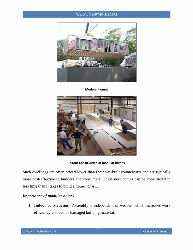
WWWVIDYARTHIPLUSCOM
WWWVIDYARTHIPLUSCOM KBALAJI 119820119812 (119852119853119851119854119836119853)
Modular homes
Indoor Construction of modular homes
Such dwellings are often priced lower than their site-built counterparts and are typically
more cost-effective to builders and consumers These new homes can be constructed in
less time than it takes to build a home on-siteldquo
Importance of modular homes
1 Indoor construction Assembly is independent of weather which increases work
efficiency and avoids damaged building material
WWWVIDYARTHIPLUSCOM
WWWVIDYARTHIPLUSCOM KBALAJI 119820119812 (119852119853119851119854119836119853)
2 Favourable pricing from suppliers Large-scale manufacturers can effectively
bargain with suppliers for discounts on materials
3 Ability to service remote locations Particularly in countries such as Australia
there can be much higher costs to build a site-built house in a remote area or an
area experiencing a construction boom such as mining towns Modular homes can
be built in major towns and sold to regional areas
4 Low waste With the same plans being constantly built the manufacturer has
records of exactly what quantity of materials is needed for a given job While
waste from a site-built dwelling may typically fill several large dumpsters waste
from a modular dwelling generates much less waste
5 Building Strength According to manufacturers modular homes are generally
designed to be initially stronger than traditional homesFor example replacing
nails with screws and adding glue to joints This is supposed to help the modules
maintain their structural integrity as they are transported on trucks to the
construction site
6 Assembly Time The modules that will combine to form the house are assembled
off-site in a factory These modules can take one to three months to be constructed
but often take as little as 10 days to actually construct when they are first started
Then they are transported to the building site where a crane is brought in to
assemble the modules togetherThe placement of the modules together generally
takes several hours or days
Mobile Homes
Mobile homes or static caravans are prefabricated homes built in factories rather than on
site and then taken to the place where they will be occupied They are usually
transported by tractor-trailers over public roads to sites which are often in rural areas or
high-density developments In some countries they are used for temporary
WWWVIDYARTHIPLUSCOM
WWWVIDYARTHIPLUSCOM KBALAJI 119820119812 (119852119853119851119854119836119853)
accommodation on campsites While these houses are usually placed in one location and
left there permanently or they have the ability to be move
Behind the work fitted at installation to hide the base there are strong trailer frames
axles wheels and tow-hitches The two major sizes are single-wides and double-wides
1 Single-wides are eighteen feet or less in width and 90 feet (27 m) or less in length
and can be towed to their site as a single unit
Double-wides are twenty feet or more wide and are 90 feet (27 m) in length or less and
are towed to their site in two separate units which are then joined together
WWWVIDYARTHIPLUSCOM
WWWVIDYARTHIPLUSCOM KBALAJI 119820119812 (119852119853119851119854119836119853)
Mobile homes
Production Transportation and Erection
Considerations in production
The general rule is that the connection device must be as lsquofoolproofrsquo as possible It
should be possible to place it in the mould correctly oriented and within the necessary
tolerances with a minimum of effort
1 Avoid congestion
At the location of connections additional reinforcing steel embedded plates
inserts block-outs etc are frequently required It is not unusual that so many items are
concentrated in a small location that very little room is left for the concrete It must be
kept in mind that reinforcing bars and prestressing strands which appear as lines on the
drawing take up real space in the elements Reinforcing bars require more space than
their nominal diameter and there must be room for the curvature of bent bars If
congestion is suspected it is helpful to draw large-scale details of the region in question
2 Avoid penetration of the forms
Units requiring holes in the forms should be avoided if possible especially in steel
moulds Exceptions to this rule can be made if there is a substantial amount of repetition
in the production Holes in the forms may be necessary not only because the units are
WWWVIDYARTHIPLUSCOM
WWWVIDYARTHIPLUSCOM KBALAJI 119820119812 (119852119853119851119854119836119853)
protruding from the elements but also for the arrangement used to keep the units in place
during casting The units must also be designed so that they do not make the dismantling
of the form impossible without damage to the form Most forms are supposed to be used
more than once Connection units to be placed in the top surface during casting should be
secured against the edges of the mould using purpose made holding devices These
devices are mostly costly make it more difficult to obtain a smooth surface or the
holding device may hamper the placement of concrete or other surface material The
various disadvantages have to be evaluated before selecting the method However if the
same steel plate is placed in the bottom of the form it can be located with great accuracy
as it can be fixed to the bottom directly
3 Reduce post-stripping work
A plant casting operation is most efficient when the product can be taken directly
to the storage area immediately after removal from the form Any operations required
after stripping and before erection such as special cleaning or finishing welding on
projecting hardware etc should be avoided These operations require additional handling
(increased possibility of damage to the elements) extra workspace and added labour
often with skilled trades Sometimes a trade-off is necessary between penetration of the
forms and post-stripping work
4 Use repetitious details
It is very desirable to repeat details as much as possible Similar details should be
identical even ifit results in a slight over-design
5 Use standard items
Hardware items such as inserts studs steel elements etc should be readily
available standard items that are preferably from more than one supplier It also
simplifies fabrication if similar product items are standardised as to size and shape There
is also less chance of error The same principle applies to reinforcing bars embedded
plates etc
WWWVIDYARTHIPLUSCOM
WWWVIDYARTHIPLUSCOM KBALAJI 119820119812 (119852119853119851119854119836119853)
6 Be aware of material limitations
Examples of this are the radius requirements for bending reinforcing bars standard
lengths for
certain sizes of inserts etc
7 Avoid non-standard tolerances
Dimensional tolerances which are specified to be more rigid than industry
standards are difficult to achieve Connections which require close-fitting parts without
provision for adjustment should be avoided as much as possible
8 Allow alternatives
Very often precasters will prefer certain details The producer should be allowed
to use alternative methods or materials provided the design requirements are met
Allowing alternative solutions willoften result in the most economical and best
performing connections
Considerations for transportation
During transportation any units protruding from the concrete element must be
shielded in order not to create a hazard to people Protruding units must be able to
withstand any shocks they can be subjected to during handling Protruding units like
reinforcing bars can in many cases be difficult to handle during transportation For
example a wall panel shall be transported standing at the edge but has reinforcing bars
protruding at the bottom This will make it necessary to build up the support on the
trucks which is costly takes time and makes the load less stable This problem can be
solved by letting the bars protrude from the top of the element but then the total height
may make it difficult to negotiate the underpasses en route The solution may then be to
have the protruding bars replaced by insert and threaded bar to screw in after the element
has been transported to the site
WWWVIDYARTHIPLUSCOM
WWWVIDYARTHIPLUSCOM KBALAJI 119820119812 (119852119853119851119854119836119853)
If protruding units do not create the kind of problems described above because
they do not stick out that much there still may be some difficulties For example corbels
pointing down during transport may necessitate a lot of additional support provisions for
the columns on the trucks The consequence can be a less stable load or decreased
loading capacity of the truck This kind of problem can be solved by making columns
with the corbels in one plane only and then place every second column lsquotop-to-bottomrsquo
on the trucks Otherwise it is also possible to look for a corbel-free solution
Considerations for Erection
To fully realise this benefit of fast erection of a precast structure and to keep the
costs within reasonable limits field connections should be kept simple In order to fulfil
the design requirements it is sometimes necessary to compromise fabrication and
erection simplicity
1 Use connections that are not weather sensitive
Materials such as grout dry pack cast-in-place concrete and epoxies need special
provisions to be placed in cold weather Welding is slower when the ambient temperature
is low If the connections are designed so that these processes must be completed before
erection can continue costly delays may result
2 Stability of the elements
Some elements may require propping shoring bracing or fastening before the
hoist can be unhooked Planning for the fewest quickest and safest possible operations to
be executed before releasing the hoist will greatly facilitate the erection
WWWVIDYARTHIPLUSCOM
WWWVIDYARTHIPLUSCOM KBALAJI 119820119812 (119852119853119851119854119836119853)
3 Stability of the structure
In every stage of the erection process the stability of the structure as a whole must
be planned and assured If not costly additional measures may have to be taken The
type of connection used may play a decisive role in this
4 Be aware of possible different loading conditions during erection
During erection loading conditions can occur which induce stresses or
deformations as well in the precast concrete units as in the connections which are higher
than those under service conditions When designing the connections due consideration
has to be paid to these effects unless special measures are taken during the erection such
as temporary supports etc to prevent such situations
5 Standardize connection types
All connections which serve similar functions within the building should be
standardized as much as possible As workmen become familiar with the procedures
required to make the connection productivity is enhanced and there is less chance for
error
Some types of connections require skilled craftsmen to accomplish for example
welding and post tensioning The fewer of these skilled trades required the more
economical the connection will be
6 Standardize sizes of components
Whenever possible such things as field bolts loose angles etc should be of
common size for all connections This reduces the chance for error and the time required
searching for the proper item
WWWVIDYARTHIPLUSCOM
WWWVIDYARTHIPLUSCOM KBALAJI 119820119812 (119852119853119851119854119836119853)
7 Use connections that are not susceptible to damage in handling
Reinforcing bars steel plates dowels and bolts that project from the precast piece
will often be damaged in handling requiring repair to make them fit especially if they
are of small diameter or thickness
Connection detail that makes erection impossible
Support solution that makes erection impossible
SHEAR WALL
Shear walls are vertical elements of the horizontal force resisting system Shear walls are
constructed to counter the effects of lateral load acting on a structure In residential
construction shear walls are straight external walls that typically form a box which
provides all of the lateral support for the building
Importance of shear wall
WWWVIDYARTHIPLUSCOM
WWWVIDYARTHIPLUSCOM KBALAJI 119820119812 (119852119853119851119854119836119853)
When shear walls are designed and constructed property and they will have the strength
and stiffness to resist the horizontal forces In building construction a rigid vertical
diaphragm capable of transferring lateral forces from exterior walls floors and roofs to
the ground foundation in a direction parallel to their planes Lateral forces caused by
wind earthquake and uneven settlement loads In addition to the weight of structure and
occupants create powerful twisting (torsion) forces These forces can literally tear (shear)
a building apart Reinforcing a frame by attaching or placing a rigid wall inside it
maintains that shape of the frame and prevents rotation at the joints shear walls are
especially important in high-rise building subjected to lateral wind and seismic forces
In the last two decades shear walls became an important part of mid high rise residential
buildings As part of an earthquake resistant building design these walls are placed in
building plans reducing lateral displacements under earthquake loads So shear wall
frame structure are obtained
Shear wall buildings are usually regular in plan and in elevation However in some
buildings lower floors are used for commercial purposes and the buildings are
characterized with larger plan dimensions at those floors
Purpose of constructing shear walls
1 Shear walls are not only designed to resist gravityvertical loads due to its self weight
amp other living moving loads) but they are also designed for lateral loads of
earthquakeswind The walls are structurally integrated with roofsfloors (diaphragms)
and other lateral
2Shear wall structural systems are more stable because their supporting area (Total
cross sectional area of all shear walls) with reference to total plans area of building is
comparatively more unlike in the case of RCC framed structures
3 Walls have to resist the uplift forces caused by the pull of the wind walls have to
resist the shear forces that try to push the walls over walls have to resist the lateral force
of the wind that tries to push the walls in and pull them away from the building
4 Walls floors and roofs to the ground foundation in a direction parallel to their planes
Lateral forces caused by wind earthquake and uneven settlement loads In addition to the
weight of structure and occupants create powerful twisting (torsion) forces These forces
can literally tear (shear) a building apart Reinforcing a frame by attaching or placing a
WWWVIDYARTHIPLUSCOM
WWWVIDYARTHIPLUSCOM KBALAJI 119820119812 (119852119853119851119854119836119853)
rigid wall inside it maintain the joints shear walls are especially important in high-rise
building subjected to lateral wind and seismic forces
In the last two decades shear walls became as important part of mid high rise residential
buildings As part of an earthquake resistant building design these walls are placed in
building plans reducing lateral displacements under earthquake loads So shear wall
frame structures are obtained
Shear wall buildings are usually regular in plan and in elevation However in some
buildings lower floors are used for commercial purposes and the buildings are
characterized with larger plan dimensions at these floors
Comparisons of shear wall with construction of conventional load bearing walls
Load bearing masonry is very brittle material Due to different kinds of stresses such as
shear tensileetc Caused by the earthquakes the conventional unreinforced brick
masonry collapses instantly during the unpredictable and sudden earthquakes
The RCC framed structures are slender When compared to shear wall concept of box
like three-dimensional structures though it is possible to design the earthquake resistant
RCC frame it requires extra-ordinary skills at design detailing and construction levels
Which cannot be anticipated in all types of construction projects
On the other hand even moderately designed shear wall structures not only more stable
but also comparatively quite ductile In safety terms it means that during very severe
earthquakes they will not suddenly collapse causing death of people They give enough
indicative warnings such as widening structural cracks yielding rods etc offering most
precious moment for people to run out off structures before they totally collapse
For structural purposes we consider the exterior walls as the shear resisting walls Forces
from the ceiling and roof diaphragms make their way to the outside along assumed paths
enter the walls and exit at the foundation
Forces on shear wall
Shear wall resist two types of forces
1 Shear forces
2 Uplift forces
Shear Forces
Shear forces are generated in stationary buildings by accelerations resulting from ground
movement and by external forces like wind amp waves This action creates shear forces
throughout the height of the wall between the top and bottom shear wall connections
Uplift Forces
WWWVIDYARTHIPLUSCOM
WWWVIDYARTHIPLUSCOM KBALAJI 119820119812 (119852119853119851119854119836119853)
Uplift forces exist on shear walls because the horizontal forces are applied to the top of
the wall These uplift forces try to lift up one end of the wall and push the other end
down In some cases the uplift force is large enough to tip the wall over Uplift forces are
greater on tall short walls uplift shear walls need hold down devices at each end when the
gravity loads cannot resist all of the uplift The hold down device then provides the
necessary uplift resistance
Classification of shear walls
1 Simple rectangular types amp flanged walls
2 Coupled shear walls
3 Rigid frame shear walls
4 Framed walls with in filled frames
5 Column supported shear walls
6 Core type shear walls
Types of shear walls
1 RC shear wall
2 Plywood shear wall
3 Mid ply shear wall
WWWVIDYARTHIPLUSCOM
WWWVIDYARTHIPLUSCOM KBALAJI 119820119812 (119852119853119851119854119836119853)
4 RC Hollow concrete Block masonry wall
5 Steel plate shear wall
RC shear wall
It consists of reinforced concrete walls and reinforced concrete slabs wall thickness varies
from 140 mm to 500 mm depending on the number of stories building age and thermal
insulation requirement In general these walls are continuous throughout the building
height however Some walls are discontinued as the steel front or basement level to allow
for commercial or parking spaces Floors slabs are either cast in-situ flat slabs or less
often Precast hollow core slabs Buildings are supported by concrete strip or mat
foundations the latter type is common for buildings with basements
Ply wood shear wall
Plywood is the traditional material used in the construction of shear walls the creation of
pre-fabricated shear panels have made it possible to inject strong shear assemblies into
small walls that fall at either side of a opening in a shear wall plywood shear wall consist
of
o Plywood to transfer shear forces
o Chords to resist tensioncompression generated by the over turning
moments
o Base connections to transfer shear to foundations
Midply shear wall
The midply shear wall is an improved timber shear wall that was developed by
redesigning the joints between shearing and finishing members So that the failure modes
observed in standard wall testing are virtually eliminated at lateral loads levels high
enough to cause failures in standard walls
RC Hollow concrete block masonry walls (RHCBM)
These walls are constructed by reinforcing the hollow concrete block masonry by taking
advantage of hollow spaces amp shapes of the hollow blocks It requires continuous steel
rods (reinforcement) both in the vertical amp horizontal directions at structurally critical
locations of the wall panels packed with the fresh grout concrete in the hollow spaces of
masonry bocks
RHCBC elements are designed both as load bearing walls for gravity loads and also as
shear walls for lateral seismic loads to safety withstand earthquakes
Steel plate shear wall
In general steel plate shear wall system consists of a steel plate wall boundary columns
and horizontal floor beams Together the steel plate wall and boundary columns act as a
vertical plate girder The column act as flanges of the vertical plate girder and the steel
WWWVIDYARTHIPLUSCOM
WWWVIDYARTHIPLUSCOM KBALAJI 119820119812 (119852119853119851119854119836119853)
plates wall act as its web The horizontal floor beams act more or less as transverse
stiffeners in a plate girder steel plate shear wall systems have been used in recent years in
highly seismic area to resist lateral loads
Thus shear walls are one of the most effective building elements in resisting lateral forces
during earthquake By constructing shear walls damages due to effect of lateral forces
due to earthquake and high winds can be minimized shear walls construction will provide
larger stiffness to the buildings there by reducing the damage to structure and its contents
Hence it is preferable to have all these prefabricate approximately of some weight very
near to the lifting capacity of the equipment
SHEAR WALL
WWWVIDYARTHIPLUSCOM
WWWVIDYARTHIPLUSCOM KBALAJI 119820119812 (119852119853119851119854119836119853)
WWWVIDYARTHIPLUSCOM
WWWVIDYARTHIPLUSCOM KBALAJI 119820119812 (119852119853119851119854119836119853)
WWWVIDYARTHIPLUSCOM
WWWVIDYARTHIPLUSCOM KBALAJI 119820119812 (119852119853119851119854119836119853)
Off-site fabrication
Off-Site fabrication is a process that incorporates prefabrication and pre-assembly The
process involves the design and manufacture of units or modules usually remote from the
work site and the installation at the site to form the permanent works at the site In its
fullest sense off-site fabrication requires a project strategy that will change the
orientation of the project process from construction to manufacture to installation
Examples of off-site fabrication are wall panels for homes wooden truss bridge spans
airport control stations
There are 4 main categories of Off-Site fabrication which is often also referred to as Off-
Site Construction These can be described as component (or sub-assembly) systems
penalized systems volumetric systems and modular systems Below these categories
different branches or technologies are being developed There are a vast number of
different systems on the market which fall into these categories and with recent advances
in digital design such as Building Information Modeling (BIM) the task of integrating
WWWVIDYARTHIPLUSCOM
WWWVIDYARTHIPLUSCOM KBALAJI 119820119812 (119852119853119851119854119836119853)
these different systems into a construction project is becoming increasingly a digital
management proposition
Unit -1
Question with answer
Part-A-
1Define prefabrication
The term prefab can apply to any construction method where the significant part of the
construction takes place off site in a factory That produces relatively large complex
features that assembled at the site into the finished building
2What is meant by modular Coordination
Modular coordination is a concept for coordinating dimension and space for which
building and component are dimensionally it used and positioned in basic units (or)
modules
The standard specify that the module basic M = 100 mm As the basic unit be used in a
square of M
3What are the characteristics of Modular concept
I) The basic module is small in terms of add size in order to provide design flexibility
yet large enough to promote simplification in the component variation in sizes
II) Industry friendly features that not only for manufacturing but also the transportation
and assembly requirements
III) Internationally accepted to support international market
4 Write out the advantages amp disadvantages of prefabrication
I) Self supporting readymade components are used so the need for formwork shuttering
and scaffolding is greatly reduced
II) On-site construction and condition is minimized
III) Less waste may occur
Disadvantages
I)Careful handling of prefabricated components such as concrete panels (or) steel and
glass Panels is reduced
II) Similarly leaks can form at joints is prefabricated component
5) Define the term Off-site fabrication
WWWVIDYARTHIPLUSCOM
WWWVIDYARTHIPLUSCOM KBALAJI 119820119812 (119852119853119851119854119836119853)
Off-site fabrication is the process that incorporates prefabrication and preassemble the
process involves the design and manufacture of units usually remote from the work site
and the installation at the site to form the permanent work at the site
6) Write short note on Production process
The production of concrete blocks consists of four basic process They are
1) Mixing
2) Moulding
3) Curing
4) Cubing
7) List out the limitations of prefabrication
I) Extra reinforcement is required to take care of handling and erection stresses
II) Temporary props may be required in some cases before the un-site concrete joints
achieve strength
III) The cracks may develop at the joints between the precart in ndashsite concrete due to
shrinkage and temperature stresses To overcome them extra steel is required across
joint
8) What are all the Prefab materials
Structural insulated panels (SIPs)
Insulating concrete forms (ICFS)
Prefab foundation system
Steel framing
Concrete framing
Large - modular system
9) Insulating concrete forms
Insulating concrete forms (ICE) are a prefab construction material consisting of hollow
EPS foam blocks that are stacked and glued together on-site creating the form that is
filled with reinforcing bars and concrete
10) Write short note on Principles of MC Concept
The principle objective of implanting MC is to improve productivity through the
reduction of wastages in the production installation process to improve quality in the
construction industry and to encourage an open system
WWWVIDYARTHIPLUSCOM
WWWVIDYARTHIPLUSCOM KBALAJI 119820119812 (119852119853119851119854119836119853)
11 Define shear wall
These are simple type and these shear walls under forces and horizontal shear along its
length are subjected to bending and shear To resist these forces the uniform
distribution of steel along its length is used in simple shear walls
12 Different classification of shear walls
1) Plain rectangular shear wall
2) Bar bell type
3) Framed shear wall
4) Coupled shear wall
5) Care type
13What is Modular Coordination
Modular coordination or MC is a dimensional system It is a dimension and space
coordination concept in which building and components are placed at their
designations based on the unit
14 How dimensional coordination is helpful in prefabricated structures
Building production is the organization and management of the plans equipment
materials and labour involved in the construction of a building while at the same time
complying with all codes rules and contractual stipulations The procedure should be
designed to run efficiently to keep the costs low and to allow returns on the
investment to be realized as early as possible
15 Explain the term basic module
Modular are terms that usually refer to upscale housing that can be any combination
of pre-engineered home parts that re delivered to the building site ready to be
assembled in a quick manner
16 What are the factors to consider in transporting of prefabricated structures
Transport device being movable from the input end to the output end of the production
line through a series of workstations said building unit being fabricated on an upper
surface of said flatbed said flatbed having an anti-friction surface on the upper surface
WWWVIDYARTHIPLUSCOM
WWWVIDYARTHIPLUSCOM KBALAJI 119820119812 (119852119853119851119854119836119853)
thereof for permitting sliding movement of said building unit relative to said transport
device
17 Explain the role of shear connectors in pre fabricated structures
Shear connectors may be spaced uniformly between the sections of maximum and zero
moment Shear connectors should have at least 1 in (254 mm) of concrete cover in all
directions and unless studs are located directly over the web stud diameters may not
exceed 25 times the beam-flange thickness With heavy concentrated loads the uniform
spacing of shear connectors may not be sufficient between a concentrated load and the
nearest point of zero moment
18 What are the special material properties in of prefabricated structures
Quicktoassemble
Cost-effective
Portablemovable
Strong
Water proof Moisture proof
Fire Resistant
19 What are the types of shear walls
Vertical Offset of Shear Walls
Stiffness shear wall
Steel shear wall
20 Write short notes on prefabrication
Prefabrication is the practice of assembling components of a structure in a factory or
other manufacturing site and transporting complete assemblies or sub-assemblies to
the construction site where the structure is to be located prefabrication in
architectural construction a technique whereby large units of a building are produced
WWWVIDYARTHIPLUSCOM
WWWVIDYARTHIPLUSCOM KBALAJI 119820119812 (119852119853119851119854119836119853)
in factories to be assembled ready-made on the building site The technique permits
the speedy erection of very large structures
21 Write any two advantages of prefabrication construction
Self-supporting ready-made components are used so the need for formwork
shuttering and scaffolding is greatly reduced
Construction time is reduced and buildings are completed sooner allowing an
earlier return of the capital invested
22 Define the term module
23 Write short notes on shear wall
A shear wall is a wall which is designed to resist shear the lateral force which causes
the bulk of damage in earthquakes
24 Write any two prefabrication problem of materials
Non availability of materials
Economy
25 Write the types of Derricks
A derrick is a lifting device composed of one mast or pole which is hinged freely at
the bottom It is controlled by lines powered by some means such as man-hauling or
motors so that the pole can move in all four directions
Hallen Derrick
Velle Derrick
Stuumllcken Derrick
26 What are the advantages of prefabricated structures
WWWVIDYARTHIPLUSCOM
WWWVIDYARTHIPLUSCOM KBALAJI 119820119812 (119852119853119851119854119836119853)
On-site construction and congestion is minimized
Quality control can be easier in a factory assembly line setting than a construction
site setting
Prefabrication can be located where skilled labour is more readily available and
costs of labour power materials space and overheads are lower
Time spent in bad weather or hazardous environments at the construction site is
minimised
27 What are the safety factors to be considered in designing
28 Explain about the location of shear wall
Lateral forces caused by wind earthquake and uneven settlement loads in addition to
the weight of structure and occupants create powerful twisting (torsional) forces
These forces can literally tear (shear) a building apart Reinforcing a frame by
attaching or placing a rigid wall inside it maintains the shape of the frame and
prevents rotation at the joints Shear walls are especially important in high-rise
buildings subject to lateral wind and seismic forces
29 What are the lateral loads in a building Live load
Wind load
Earthquake load 30What are the lateral load resisting elements in a building (AUC NovDec 2013) Vertical Elements
Moment
Resisting Frames
Walls
Bearing walls Shear Walls Structural Walls
Gravity Frame + Walls
ldquoDualrdquo System (Frame + Wall)
WWWVIDYARTHIPLUSCOM
WWWVIDYARTHIPLUSCOM KBALAJI 119820119812 (119852119853119851119854119836119853)
Vertical Truss
Tube System
Bundled
Tube System FloorDiaphragm
Foundation
WWWVIDYARTHIPLUSCOM
WWWVIDYARTHIPLUSCOM KBALAJI 119820119812 (119852119853119851119854119836119853)
Part-B
1Explain Modular Coordination in detail
Modular coordination means the interdependent arrangement of a dimension based on a
primary value accepted as a module The strict observance of rules of modular
coordination facilitated
1 Assembly of single components into large components
2 Fewest possible different types of component
3 Minimum wastage of cutting needed
Modular coordination is the basis for a standardization of a mass production of
component A
set of rules would be adequate for meeting the requirements of conventional and
prefabricated construction These rules are adaptable for
a The planning grid in both directions of the horizontal plan shall be
1 3M for residential and institutional buildings
2 For industrial buildings
WWWVIDYARTHIPLUSCOM
WWWVIDYARTHIPLUSCOM KBALAJI 119820119812 (119852119853119851119854119836119853)
15M for spans up to 12m
30M for spans between 12m and 18m
60M for spans over 18m
The centre lines of load bearing walls shall coincide with the grid lines
b In case of external walls the grid lines shall coincide with the centre line of the wall or
a line on the wall 5 cm from the internal face of the wall
C The planning module in the vertical direction shall be 1M up to and including a ht of
28M
d Preferred increments for the still heights doors windows and other fenestration shall
be
1M
e In case of internal columns the grid lines shall coincide with the centre lines of
columns In case of external columns the grid lines shall coincide with the centre lines of
the columns in the storey or a line in the column from the internal face of the column in
the topmost storey A basic module can be represented as module and for larger project
modules are represented a Mp
For eg For a project module in horizontal coordination the component can be of 30cm
and for vertical component size be of 10cm
The storey height is fixed between finished floor levels as 28m and if the thickness of
slab is lt15cm storey height is fixed as 27m The centre distance between the load
bearing walls can be chose from a set of modules The use of other dimensions is not
allowed
In the design of a building modular grid can be used consisting of parallel line spaced at
a value of module M or Mp and a grid line chosen as a base for setting out a part of a
building becomes a modular axis In the fig (a) a typical grid is chosen for load bearing
walls without duct The interior walls are placed so that their centre lines coincide with
the modular axis In the fig (b) a grid is shown for load bearing walls with hollow ducts
in between The centre line of the grid is found by deducting the size of duct
WWWVIDYARTHIPLUSCOM
WWWVIDYARTHIPLUSCOM KBALAJI 119820119812 (119852119853119851119854119836119853)
2Systems of prefabrication
System is referred to a particular method of construction of buildings using the
prefabricated components which are inter related in functions and are produced to a set of
instructions With certain constraints several plans are possible using the same set of
components the degree of flexibility varies from system to system However in all the
systems there is a certain order and discipline The system of prefabricated construction
depends on the extend of the use of prefab components their characteristics to be
considered in devising a system
i Intensified usage of spaces
ii Straight and simple walling scheme
iii Limited sizes and numbers of components
iv Limited opening in bearing walls
v Regulated locations of partitions
vi Standardized service and stair units
vii Limited sizes of doors and windows with regulated positions
viii Structural clarity and efficiency
ix Suitability for adoption in low rise and high rise blocks
x Ease of manufacturing storing and transporting
xi Speed and ease of erection
xii Simple jointing system
a) Based on Disuniting of member
b) Based on the construction
WWWVIDYARTHIPLUSCOM
WWWVIDYARTHIPLUSCOM KBALAJI 119820119812 (119852119853119851119854119836119853)
Based on Disuniting of member
1 System consisting of linear member disunited at joints
2 System for prefabricates of entire rigid frame
3 System consisting of ITU of straight members disunited at points of minimum
moment
4 Two hinged and three hinged arches
System consisting of linear member disunited at joints
Advantage
Disuniting at joints gives linear member This means that a great advantage and facilitates
from the view point manufacture and assembly
Disadvantage
1 Joints are at corners ie at points of maximum moment values so forming the joint is
difficult
2 Joints must be over dimensioned to cope with in-situ concreting And one alternate
solution to replace moment resistant joints by hinged connection
System for prefabricates of entire rigid frame
WWWVIDYARTHIPLUSCOM
WWWVIDYARTHIPLUSCOM KBALAJI 119820119812 (119852119853119851119854119836119853)
In this system to reduce the no of joints and to precast larger numbers I one piece leads
to the prefabrication of entire frame Production of the frames does not cause any
particular trouble but the hoisting is more difficult and requires careful preparation The
stress distribution of straight members during hoisting is in general statistically
determinate
Advantage
1 It is ideal for site prefabrication
2 Small number of joints so rapid prefabrication work is possible
3 Suitable for long walls consisting of great number of uniform frames
System consisting of ITU of straight members disunited at points of minimum
moment
WWWVIDYARTHIPLUSCOM
WWWVIDYARTHIPLUSCOM KBALAJI 119820119812 (119852119853119851119854119836119853)
WWWVIDYARTHIPLUSCOM
WWWVIDYARTHIPLUSCOM KBALAJI 119820119812 (119852119853119851119854119836119853)
Another method of disuniting of structures is by division into different membranes at
points where the moments are thin or smallest This method is called as lambda method
Using this method hinge joints are made
Advantage
1 Functions are made at points of minimum moments or at points of contra flexure
2 Disuniting the main girder in this manner makes the application of different skylights
possible
Disadvantage
1 Hosting and temperature bracing of L joined asymmetric frame members is
WWWVIDYARTHIPLUSCOM
WWWVIDYARTHIPLUSCOM KBALAJI 119820119812 (119852119853119851119854119836119853)
particularly complicated
2 Temperature resting of frame member on each other necessitates the use of
cantilevers having half depth and proper forming of this cause difficulty
Two hinged and three hinged arches
Arched structures are normally two hinged and three hinged arches Arched structures are
normally used for bridging span more than 20-25m Their production and placing is more
difficult than straight members Arch can be two hinged and three hinged but they can
also be fixed at footings and can be constructed with or without tie
These members are generally precast and assembled in statistically determinant three
hinged variance and middle hinge is only eliminated after placing is finished The
reinforcing bars protruding both sides are welded together and the joint between the
members is filled in with insitu concrete
Arch structure can be precast in either vertical or horizontal positions In the first case
shuttering made of timber or concrete is required having the same curvature s the arch
itself
The prefabrication of larger arches in the horizontal position is found to be more
economical
The construction of arch trusses can be properly carried out in the horizontal position
only
WWWVIDYARTHIPLUSCOM
WWWVIDYARTHIPLUSCOM KBALAJI 119820119812 (119852119853119851119854119836119853)
3Methods of prefabrication
Site prefabrication- for large prefabricates
Plant prefabrication- large scale production
Site prefabrication
1 The RC members are produced t the site in the open air chiefly in the open air or in
the temporary sheds
2 The difficulties in construction in general are felt in this mechanization can case
3 Mechanization cannot be of such high degree as site PF is done for smaller duration
of time
4 When the pre fabricates are of large size it is difficult to transport the pre fabricates to
the site
5 In comparison with plant prefabrication transportation of the members are not needed
As large members are not transported the design and weight of the prefabricates are not
limited
Plant prefabrication
1 The members produced are to be transported t the place of construction this accounts
for about 10-15 of the cost of production and assembling
2 Certain restriction is made in the dimension of prefabrication leading to restraints in
the design and development of prefabrication
3 Prefabrication is appropriate for mass production for manufacture of standardized
members
4 Needs costly materials for batching and production
5 This method is most suited in the case of small prefabricates which are to be
prefabricated in very large number
Plant prefabrication is done under permanent plant or factories It is done under the
covered roof so the effect of weather does not affect the work So the quality and strength
of the members can be improved considerably Plant prefabrication reduces the cost of
prefabrication if the number of prefabricate needed is more
Dimensions of prefabricate
There are 3 commonly known dimension for the prefabricates
1 The design of the erection dimension governing the dimensional coordination of the
prefabricates
2 Theoretical dimension
3 The actual dimension of the element when delivered the design dimension should be a
multiple of a basic module size m or of a module lap
WWWVIDYARTHIPLUSCOM
WWWVIDYARTHIPLUSCOM KBALAJI 119820119812 (119852119853119851119854119836119853)
Production of prefabricates
Production techniques involved are
1 Stand method
2 Conveyor method or line method
3 Aggregate method
Stand Method
In this method the prefabrication mature where they are moulded while the production
teams moves to successive stands The bed on which prefabricates are cast may be fixed
or
movable Tilting forms are often used and in this method steam curing is generally done
Conveyor belt method
The whole production is split up in to series operations carried out at separate successive
and permanent points served by specialized teams The movement of the mould or
prefabricate one point to other vary by means of conveyor belt trolleys
The rigid steel forms are assembled at station 1 where they are mould oil to reduce the
adhesion of concrete The conveyor moves front 1 to 2 where prestressing wires are fixed
amp in the next station anchoring of the wires is carried out The prepared mould is then
carried to the station 1ie casting station After casting it is shifted to the vibrating table amp
finally stacked station 5 for setting After that it is passed through tunnel autoclave for
curing After steam curing move too station 7 for demoulding amp is finally stacked 8
Aggregate method
In the aggregate method aggregate describes large complex permanently installed
machines amp mechanical appliances which carry out most of the separate operations
involved in the casting of the concrete composition The stand is operated by a permanent
team amp the only move the prefabricate makes is to the maturing point
Aggregate method is used in the production of multi duct hollow floor panel in Poland
At production point the reinforcement is fixed in the form amp remote controlled
aggregate(machine)inserts the duct formers castamp vibrates the concrete floats the top
of the floor The prepared prefabricate then move to the autoclave chamber in which
hardening of concrete is accelerate In many factories combined technology are employed
when complex prefabricate are required
Advantages
1The stand technique is the most flexible one It is used in varying degrees of
mechanization in all kinds of prefabricate factories
2It is simple amp less capital is required It can be used for field prefabricate also
WWWVIDYARTHIPLUSCOM
WWWVIDYARTHIPLUSCOM KBALAJI 119820119812 (119852119853119851119854119836119853)
3Aggregate method is used for large scale production in which case number of
machineries is required
4 Explain specific requirements in layout of of prefabricated plants
WWWVIDYARTHIPLUSCOM
WWWVIDYARTHIPLUSCOM KBALAJI 119820119812 (119852119853119851119854119836119853)
WWWVIDYARTHIPLUSCOM
WWWVIDYARTHIPLUSCOM KBALAJI 119820119812 (119852119853119851119854119836119853)
5 Explain with neat sketch of the types of shear wall
WWWVIDYARTHIPLUSCOM
WWWVIDYARTHIPLUSCOM KBALAJI 119820119812 (119852119853119851119854119836119853)
WWWVIDYARTHIPLUSCOM
WWWVIDYARTHIPLUSCOM KBALAJI 119820119812 (119852119853119851119854119836119853)
6 What is the code use for prefabricated structures
WWWVIDYARTHIPLUSCOM
WWWVIDYARTHIPLUSCOM KBALAJI 119820119812 (119852119853119851119854119836119853)
7 Explain in detail various design consideration in the design of precast construction
WWWVIDYARTHIPLUSCOM
WWWVIDYARTHIPLUSCOM KBALAJI 119820119812 (119852119853119851119854119836119853)
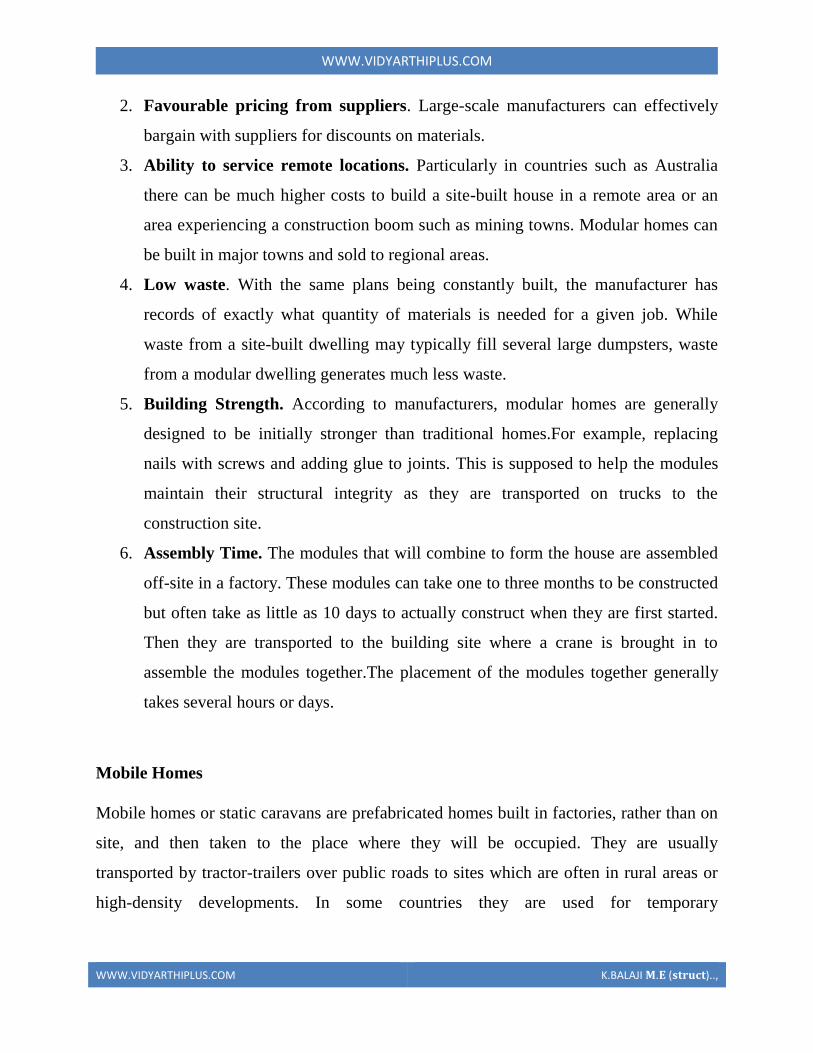
WWWVIDYARTHIPLUSCOM
WWWVIDYARTHIPLUSCOM KBALAJI 119820119812 (119852119853119851119854119836119853)
accommodation on campsites While these houses are usually placed in one location and
left there permanently or they have the ability to be move
Behind the work fitted at installation to hide the base there are strong trailer frames
axles wheels and tow-hitches The two major sizes are single-wides and double-wides
1 Single-wides are eighteen feet or less in width and 90 feet (27 m) or less in length
and can be towed to their site as a single unit
Double-wides are twenty feet or more wide and are 90 feet (27 m) in length or less and
are towed to their site in two separate units which are then joined together
WWWVIDYARTHIPLUSCOM
WWWVIDYARTHIPLUSCOM KBALAJI 119820119812 (119852119853119851119854119836119853)
Mobile homes
Production Transportation and Erection
Considerations in production
The general rule is that the connection device must be as lsquofoolproofrsquo as possible It
should be possible to place it in the mould correctly oriented and within the necessary
tolerances with a minimum of effort
1 Avoid congestion
At the location of connections additional reinforcing steel embedded plates
inserts block-outs etc are frequently required It is not unusual that so many items are
concentrated in a small location that very little room is left for the concrete It must be
kept in mind that reinforcing bars and prestressing strands which appear as lines on the
drawing take up real space in the elements Reinforcing bars require more space than
their nominal diameter and there must be room for the curvature of bent bars If
congestion is suspected it is helpful to draw large-scale details of the region in question
2 Avoid penetration of the forms
Units requiring holes in the forms should be avoided if possible especially in steel
moulds Exceptions to this rule can be made if there is a substantial amount of repetition
in the production Holes in the forms may be necessary not only because the units are
WWWVIDYARTHIPLUSCOM
WWWVIDYARTHIPLUSCOM KBALAJI 119820119812 (119852119853119851119854119836119853)
protruding from the elements but also for the arrangement used to keep the units in place
during casting The units must also be designed so that they do not make the dismantling
of the form impossible without damage to the form Most forms are supposed to be used
more than once Connection units to be placed in the top surface during casting should be
secured against the edges of the mould using purpose made holding devices These
devices are mostly costly make it more difficult to obtain a smooth surface or the
holding device may hamper the placement of concrete or other surface material The
various disadvantages have to be evaluated before selecting the method However if the
same steel plate is placed in the bottom of the form it can be located with great accuracy
as it can be fixed to the bottom directly
3 Reduce post-stripping work
A plant casting operation is most efficient when the product can be taken directly
to the storage area immediately after removal from the form Any operations required
after stripping and before erection such as special cleaning or finishing welding on
projecting hardware etc should be avoided These operations require additional handling
(increased possibility of damage to the elements) extra workspace and added labour
often with skilled trades Sometimes a trade-off is necessary between penetration of the
forms and post-stripping work
4 Use repetitious details
It is very desirable to repeat details as much as possible Similar details should be
identical even ifit results in a slight over-design
5 Use standard items
Hardware items such as inserts studs steel elements etc should be readily
available standard items that are preferably from more than one supplier It also
simplifies fabrication if similar product items are standardised as to size and shape There
is also less chance of error The same principle applies to reinforcing bars embedded
plates etc
WWWVIDYARTHIPLUSCOM
WWWVIDYARTHIPLUSCOM KBALAJI 119820119812 (119852119853119851119854119836119853)
6 Be aware of material limitations
Examples of this are the radius requirements for bending reinforcing bars standard
lengths for
certain sizes of inserts etc
7 Avoid non-standard tolerances
Dimensional tolerances which are specified to be more rigid than industry
standards are difficult to achieve Connections which require close-fitting parts without
provision for adjustment should be avoided as much as possible
8 Allow alternatives
Very often precasters will prefer certain details The producer should be allowed
to use alternative methods or materials provided the design requirements are met
Allowing alternative solutions willoften result in the most economical and best
performing connections
Considerations for transportation
During transportation any units protruding from the concrete element must be
shielded in order not to create a hazard to people Protruding units must be able to
withstand any shocks they can be subjected to during handling Protruding units like
reinforcing bars can in many cases be difficult to handle during transportation For
example a wall panel shall be transported standing at the edge but has reinforcing bars
protruding at the bottom This will make it necessary to build up the support on the
trucks which is costly takes time and makes the load less stable This problem can be
solved by letting the bars protrude from the top of the element but then the total height
may make it difficult to negotiate the underpasses en route The solution may then be to
have the protruding bars replaced by insert and threaded bar to screw in after the element
has been transported to the site
WWWVIDYARTHIPLUSCOM
WWWVIDYARTHIPLUSCOM KBALAJI 119820119812 (119852119853119851119854119836119853)
If protruding units do not create the kind of problems described above because
they do not stick out that much there still may be some difficulties For example corbels
pointing down during transport may necessitate a lot of additional support provisions for
the columns on the trucks The consequence can be a less stable load or decreased
loading capacity of the truck This kind of problem can be solved by making columns
with the corbels in one plane only and then place every second column lsquotop-to-bottomrsquo
on the trucks Otherwise it is also possible to look for a corbel-free solution
Considerations for Erection
To fully realise this benefit of fast erection of a precast structure and to keep the
costs within reasonable limits field connections should be kept simple In order to fulfil
the design requirements it is sometimes necessary to compromise fabrication and
erection simplicity
1 Use connections that are not weather sensitive
Materials such as grout dry pack cast-in-place concrete and epoxies need special
provisions to be placed in cold weather Welding is slower when the ambient temperature
is low If the connections are designed so that these processes must be completed before
erection can continue costly delays may result
2 Stability of the elements
Some elements may require propping shoring bracing or fastening before the
hoist can be unhooked Planning for the fewest quickest and safest possible operations to
be executed before releasing the hoist will greatly facilitate the erection
WWWVIDYARTHIPLUSCOM
WWWVIDYARTHIPLUSCOM KBALAJI 119820119812 (119852119853119851119854119836119853)
3 Stability of the structure
In every stage of the erection process the stability of the structure as a whole must
be planned and assured If not costly additional measures may have to be taken The
type of connection used may play a decisive role in this
4 Be aware of possible different loading conditions during erection
During erection loading conditions can occur which induce stresses or
deformations as well in the precast concrete units as in the connections which are higher
than those under service conditions When designing the connections due consideration
has to be paid to these effects unless special measures are taken during the erection such
as temporary supports etc to prevent such situations
5 Standardize connection types
All connections which serve similar functions within the building should be
standardized as much as possible As workmen become familiar with the procedures
required to make the connection productivity is enhanced and there is less chance for
error
Some types of connections require skilled craftsmen to accomplish for example
welding and post tensioning The fewer of these skilled trades required the more
economical the connection will be
6 Standardize sizes of components
Whenever possible such things as field bolts loose angles etc should be of
common size for all connections This reduces the chance for error and the time required
searching for the proper item
WWWVIDYARTHIPLUSCOM
WWWVIDYARTHIPLUSCOM KBALAJI 119820119812 (119852119853119851119854119836119853)
7 Use connections that are not susceptible to damage in handling
Reinforcing bars steel plates dowels and bolts that project from the precast piece
will often be damaged in handling requiring repair to make them fit especially if they
are of small diameter or thickness
Connection detail that makes erection impossible
Support solution that makes erection impossible
SHEAR WALL
Shear walls are vertical elements of the horizontal force resisting system Shear walls are
constructed to counter the effects of lateral load acting on a structure In residential
construction shear walls are straight external walls that typically form a box which
provides all of the lateral support for the building
Importance of shear wall
WWWVIDYARTHIPLUSCOM
WWWVIDYARTHIPLUSCOM KBALAJI 119820119812 (119852119853119851119854119836119853)
When shear walls are designed and constructed property and they will have the strength
and stiffness to resist the horizontal forces In building construction a rigid vertical
diaphragm capable of transferring lateral forces from exterior walls floors and roofs to
the ground foundation in a direction parallel to their planes Lateral forces caused by
wind earthquake and uneven settlement loads In addition to the weight of structure and
occupants create powerful twisting (torsion) forces These forces can literally tear (shear)
a building apart Reinforcing a frame by attaching or placing a rigid wall inside it
maintains that shape of the frame and prevents rotation at the joints shear walls are
especially important in high-rise building subjected to lateral wind and seismic forces
In the last two decades shear walls became an important part of mid high rise residential
buildings As part of an earthquake resistant building design these walls are placed in
building plans reducing lateral displacements under earthquake loads So shear wall
frame structure are obtained
Shear wall buildings are usually regular in plan and in elevation However in some
buildings lower floors are used for commercial purposes and the buildings are
characterized with larger plan dimensions at those floors
Purpose of constructing shear walls
1 Shear walls are not only designed to resist gravityvertical loads due to its self weight
amp other living moving loads) but they are also designed for lateral loads of
earthquakeswind The walls are structurally integrated with roofsfloors (diaphragms)
and other lateral
2Shear wall structural systems are more stable because their supporting area (Total
cross sectional area of all shear walls) with reference to total plans area of building is
comparatively more unlike in the case of RCC framed structures
3 Walls have to resist the uplift forces caused by the pull of the wind walls have to
resist the shear forces that try to push the walls over walls have to resist the lateral force
of the wind that tries to push the walls in and pull them away from the building
4 Walls floors and roofs to the ground foundation in a direction parallel to their planes
Lateral forces caused by wind earthquake and uneven settlement loads In addition to the
weight of structure and occupants create powerful twisting (torsion) forces These forces
can literally tear (shear) a building apart Reinforcing a frame by attaching or placing a
WWWVIDYARTHIPLUSCOM
WWWVIDYARTHIPLUSCOM KBALAJI 119820119812 (119852119853119851119854119836119853)
rigid wall inside it maintain the joints shear walls are especially important in high-rise
building subjected to lateral wind and seismic forces
In the last two decades shear walls became as important part of mid high rise residential
buildings As part of an earthquake resistant building design these walls are placed in
building plans reducing lateral displacements under earthquake loads So shear wall
frame structures are obtained
Shear wall buildings are usually regular in plan and in elevation However in some
buildings lower floors are used for commercial purposes and the buildings are
characterized with larger plan dimensions at these floors
Comparisons of shear wall with construction of conventional load bearing walls
Load bearing masonry is very brittle material Due to different kinds of stresses such as
shear tensileetc Caused by the earthquakes the conventional unreinforced brick
masonry collapses instantly during the unpredictable and sudden earthquakes
The RCC framed structures are slender When compared to shear wall concept of box
like three-dimensional structures though it is possible to design the earthquake resistant
RCC frame it requires extra-ordinary skills at design detailing and construction levels
Which cannot be anticipated in all types of construction projects
On the other hand even moderately designed shear wall structures not only more stable
but also comparatively quite ductile In safety terms it means that during very severe
earthquakes they will not suddenly collapse causing death of people They give enough
indicative warnings such as widening structural cracks yielding rods etc offering most
precious moment for people to run out off structures before they totally collapse
For structural purposes we consider the exterior walls as the shear resisting walls Forces
from the ceiling and roof diaphragms make their way to the outside along assumed paths
enter the walls and exit at the foundation
Forces on shear wall
Shear wall resist two types of forces
1 Shear forces
2 Uplift forces
Shear Forces
Shear forces are generated in stationary buildings by accelerations resulting from ground
movement and by external forces like wind amp waves This action creates shear forces
throughout the height of the wall between the top and bottom shear wall connections
Uplift Forces
WWWVIDYARTHIPLUSCOM
WWWVIDYARTHIPLUSCOM KBALAJI 119820119812 (119852119853119851119854119836119853)
Uplift forces exist on shear walls because the horizontal forces are applied to the top of
the wall These uplift forces try to lift up one end of the wall and push the other end
down In some cases the uplift force is large enough to tip the wall over Uplift forces are
greater on tall short walls uplift shear walls need hold down devices at each end when the
gravity loads cannot resist all of the uplift The hold down device then provides the
necessary uplift resistance
Classification of shear walls
1 Simple rectangular types amp flanged walls
2 Coupled shear walls
3 Rigid frame shear walls
4 Framed walls with in filled frames
5 Column supported shear walls
6 Core type shear walls
Types of shear walls
1 RC shear wall
2 Plywood shear wall
3 Mid ply shear wall
WWWVIDYARTHIPLUSCOM
WWWVIDYARTHIPLUSCOM KBALAJI 119820119812 (119852119853119851119854119836119853)
4 RC Hollow concrete Block masonry wall
5 Steel plate shear wall
RC shear wall
It consists of reinforced concrete walls and reinforced concrete slabs wall thickness varies
from 140 mm to 500 mm depending on the number of stories building age and thermal
insulation requirement In general these walls are continuous throughout the building
height however Some walls are discontinued as the steel front or basement level to allow
for commercial or parking spaces Floors slabs are either cast in-situ flat slabs or less
often Precast hollow core slabs Buildings are supported by concrete strip or mat
foundations the latter type is common for buildings with basements
Ply wood shear wall
Plywood is the traditional material used in the construction of shear walls the creation of
pre-fabricated shear panels have made it possible to inject strong shear assemblies into
small walls that fall at either side of a opening in a shear wall plywood shear wall consist
of
o Plywood to transfer shear forces
o Chords to resist tensioncompression generated by the over turning
moments
o Base connections to transfer shear to foundations
Midply shear wall
The midply shear wall is an improved timber shear wall that was developed by
redesigning the joints between shearing and finishing members So that the failure modes
observed in standard wall testing are virtually eliminated at lateral loads levels high
enough to cause failures in standard walls
RC Hollow concrete block masonry walls (RHCBM)
These walls are constructed by reinforcing the hollow concrete block masonry by taking
advantage of hollow spaces amp shapes of the hollow blocks It requires continuous steel
rods (reinforcement) both in the vertical amp horizontal directions at structurally critical
locations of the wall panels packed with the fresh grout concrete in the hollow spaces of
masonry bocks
RHCBC elements are designed both as load bearing walls for gravity loads and also as
shear walls for lateral seismic loads to safety withstand earthquakes
Steel plate shear wall
In general steel plate shear wall system consists of a steel plate wall boundary columns
and horizontal floor beams Together the steel plate wall and boundary columns act as a
vertical plate girder The column act as flanges of the vertical plate girder and the steel
WWWVIDYARTHIPLUSCOM
WWWVIDYARTHIPLUSCOM KBALAJI 119820119812 (119852119853119851119854119836119853)
plates wall act as its web The horizontal floor beams act more or less as transverse
stiffeners in a plate girder steel plate shear wall systems have been used in recent years in
highly seismic area to resist lateral loads
Thus shear walls are one of the most effective building elements in resisting lateral forces
during earthquake By constructing shear walls damages due to effect of lateral forces
due to earthquake and high winds can be minimized shear walls construction will provide
larger stiffness to the buildings there by reducing the damage to structure and its contents
Hence it is preferable to have all these prefabricate approximately of some weight very
near to the lifting capacity of the equipment
SHEAR WALL
WWWVIDYARTHIPLUSCOM
WWWVIDYARTHIPLUSCOM KBALAJI 119820119812 (119852119853119851119854119836119853)
WWWVIDYARTHIPLUSCOM
WWWVIDYARTHIPLUSCOM KBALAJI 119820119812 (119852119853119851119854119836119853)
WWWVIDYARTHIPLUSCOM
WWWVIDYARTHIPLUSCOM KBALAJI 119820119812 (119852119853119851119854119836119853)
Off-site fabrication
Off-Site fabrication is a process that incorporates prefabrication and pre-assembly The
process involves the design and manufacture of units or modules usually remote from the
work site and the installation at the site to form the permanent works at the site In its
fullest sense off-site fabrication requires a project strategy that will change the
orientation of the project process from construction to manufacture to installation
Examples of off-site fabrication are wall panels for homes wooden truss bridge spans
airport control stations
There are 4 main categories of Off-Site fabrication which is often also referred to as Off-
Site Construction These can be described as component (or sub-assembly) systems
penalized systems volumetric systems and modular systems Below these categories
different branches or technologies are being developed There are a vast number of
different systems on the market which fall into these categories and with recent advances
in digital design such as Building Information Modeling (BIM) the task of integrating
WWWVIDYARTHIPLUSCOM
WWWVIDYARTHIPLUSCOM KBALAJI 119820119812 (119852119853119851119854119836119853)
these different systems into a construction project is becoming increasingly a digital
management proposition
Unit -1
Question with answer
Part-A-
1Define prefabrication
The term prefab can apply to any construction method where the significant part of the
construction takes place off site in a factory That produces relatively large complex
features that assembled at the site into the finished building
2What is meant by modular Coordination
Modular coordination is a concept for coordinating dimension and space for which
building and component are dimensionally it used and positioned in basic units (or)
modules
The standard specify that the module basic M = 100 mm As the basic unit be used in a
square of M
3What are the characteristics of Modular concept
I) The basic module is small in terms of add size in order to provide design flexibility
yet large enough to promote simplification in the component variation in sizes
II) Industry friendly features that not only for manufacturing but also the transportation
and assembly requirements
III) Internationally accepted to support international market
4 Write out the advantages amp disadvantages of prefabrication
I) Self supporting readymade components are used so the need for formwork shuttering
and scaffolding is greatly reduced
II) On-site construction and condition is minimized
III) Less waste may occur
Disadvantages
I)Careful handling of prefabricated components such as concrete panels (or) steel and
glass Panels is reduced
II) Similarly leaks can form at joints is prefabricated component
5) Define the term Off-site fabrication
WWWVIDYARTHIPLUSCOM
WWWVIDYARTHIPLUSCOM KBALAJI 119820119812 (119852119853119851119854119836119853)
Off-site fabrication is the process that incorporates prefabrication and preassemble the
process involves the design and manufacture of units usually remote from the work site
and the installation at the site to form the permanent work at the site
6) Write short note on Production process
The production of concrete blocks consists of four basic process They are
1) Mixing
2) Moulding
3) Curing
4) Cubing
7) List out the limitations of prefabrication
I) Extra reinforcement is required to take care of handling and erection stresses
II) Temporary props may be required in some cases before the un-site concrete joints
achieve strength
III) The cracks may develop at the joints between the precart in ndashsite concrete due to
shrinkage and temperature stresses To overcome them extra steel is required across
joint
8) What are all the Prefab materials
Structural insulated panels (SIPs)
Insulating concrete forms (ICFS)
Prefab foundation system
Steel framing
Concrete framing
Large - modular system
9) Insulating concrete forms
Insulating concrete forms (ICE) are a prefab construction material consisting of hollow
EPS foam blocks that are stacked and glued together on-site creating the form that is
filled with reinforcing bars and concrete
10) Write short note on Principles of MC Concept
The principle objective of implanting MC is to improve productivity through the
reduction of wastages in the production installation process to improve quality in the
construction industry and to encourage an open system
WWWVIDYARTHIPLUSCOM
WWWVIDYARTHIPLUSCOM KBALAJI 119820119812 (119852119853119851119854119836119853)
11 Define shear wall
These are simple type and these shear walls under forces and horizontal shear along its
length are subjected to bending and shear To resist these forces the uniform
distribution of steel along its length is used in simple shear walls
12 Different classification of shear walls
1) Plain rectangular shear wall
2) Bar bell type
3) Framed shear wall
4) Coupled shear wall
5) Care type
13What is Modular Coordination
Modular coordination or MC is a dimensional system It is a dimension and space
coordination concept in which building and components are placed at their
designations based on the unit
14 How dimensional coordination is helpful in prefabricated structures
Building production is the organization and management of the plans equipment
materials and labour involved in the construction of a building while at the same time
complying with all codes rules and contractual stipulations The procedure should be
designed to run efficiently to keep the costs low and to allow returns on the
investment to be realized as early as possible
15 Explain the term basic module
Modular are terms that usually refer to upscale housing that can be any combination
of pre-engineered home parts that re delivered to the building site ready to be
assembled in a quick manner
16 What are the factors to consider in transporting of prefabricated structures
Transport device being movable from the input end to the output end of the production
line through a series of workstations said building unit being fabricated on an upper
surface of said flatbed said flatbed having an anti-friction surface on the upper surface
WWWVIDYARTHIPLUSCOM
WWWVIDYARTHIPLUSCOM KBALAJI 119820119812 (119852119853119851119854119836119853)
thereof for permitting sliding movement of said building unit relative to said transport
device
17 Explain the role of shear connectors in pre fabricated structures
Shear connectors may be spaced uniformly between the sections of maximum and zero
moment Shear connectors should have at least 1 in (254 mm) of concrete cover in all
directions and unless studs are located directly over the web stud diameters may not
exceed 25 times the beam-flange thickness With heavy concentrated loads the uniform
spacing of shear connectors may not be sufficient between a concentrated load and the
nearest point of zero moment
18 What are the special material properties in of prefabricated structures
Quicktoassemble
Cost-effective
Portablemovable
Strong
Water proof Moisture proof
Fire Resistant
19 What are the types of shear walls
Vertical Offset of Shear Walls
Stiffness shear wall
Steel shear wall
20 Write short notes on prefabrication
Prefabrication is the practice of assembling components of a structure in a factory or
other manufacturing site and transporting complete assemblies or sub-assemblies to
the construction site where the structure is to be located prefabrication in
architectural construction a technique whereby large units of a building are produced
WWWVIDYARTHIPLUSCOM
WWWVIDYARTHIPLUSCOM KBALAJI 119820119812 (119852119853119851119854119836119853)
in factories to be assembled ready-made on the building site The technique permits
the speedy erection of very large structures
21 Write any two advantages of prefabrication construction
Self-supporting ready-made components are used so the need for formwork
shuttering and scaffolding is greatly reduced
Construction time is reduced and buildings are completed sooner allowing an
earlier return of the capital invested
22 Define the term module
23 Write short notes on shear wall
A shear wall is a wall which is designed to resist shear the lateral force which causes
the bulk of damage in earthquakes
24 Write any two prefabrication problem of materials
Non availability of materials
Economy
25 Write the types of Derricks
A derrick is a lifting device composed of one mast or pole which is hinged freely at
the bottom It is controlled by lines powered by some means such as man-hauling or
motors so that the pole can move in all four directions
Hallen Derrick
Velle Derrick
Stuumllcken Derrick
26 What are the advantages of prefabricated structures
WWWVIDYARTHIPLUSCOM
WWWVIDYARTHIPLUSCOM KBALAJI 119820119812 (119852119853119851119854119836119853)
On-site construction and congestion is minimized
Quality control can be easier in a factory assembly line setting than a construction
site setting
Prefabrication can be located where skilled labour is more readily available and
costs of labour power materials space and overheads are lower
Time spent in bad weather or hazardous environments at the construction site is
minimised
27 What are the safety factors to be considered in designing
28 Explain about the location of shear wall
Lateral forces caused by wind earthquake and uneven settlement loads in addition to
the weight of structure and occupants create powerful twisting (torsional) forces
These forces can literally tear (shear) a building apart Reinforcing a frame by
attaching or placing a rigid wall inside it maintains the shape of the frame and
prevents rotation at the joints Shear walls are especially important in high-rise
buildings subject to lateral wind and seismic forces
29 What are the lateral loads in a building Live load
Wind load
Earthquake load 30What are the lateral load resisting elements in a building (AUC NovDec 2013) Vertical Elements
Moment
Resisting Frames
Walls
Bearing walls Shear Walls Structural Walls
Gravity Frame + Walls
ldquoDualrdquo System (Frame + Wall)
WWWVIDYARTHIPLUSCOM
WWWVIDYARTHIPLUSCOM KBALAJI 119820119812 (119852119853119851119854119836119853)
Vertical Truss
Tube System
Bundled
Tube System FloorDiaphragm
Foundation
WWWVIDYARTHIPLUSCOM
WWWVIDYARTHIPLUSCOM KBALAJI 119820119812 (119852119853119851119854119836119853)
Part-B
1Explain Modular Coordination in detail
Modular coordination means the interdependent arrangement of a dimension based on a
primary value accepted as a module The strict observance of rules of modular
coordination facilitated
1 Assembly of single components into large components
2 Fewest possible different types of component
3 Minimum wastage of cutting needed
Modular coordination is the basis for a standardization of a mass production of
component A
set of rules would be adequate for meeting the requirements of conventional and
prefabricated construction These rules are adaptable for
a The planning grid in both directions of the horizontal plan shall be
1 3M for residential and institutional buildings
2 For industrial buildings
WWWVIDYARTHIPLUSCOM
WWWVIDYARTHIPLUSCOM KBALAJI 119820119812 (119852119853119851119854119836119853)
15M for spans up to 12m
30M for spans between 12m and 18m
60M for spans over 18m
The centre lines of load bearing walls shall coincide with the grid lines
b In case of external walls the grid lines shall coincide with the centre line of the wall or
a line on the wall 5 cm from the internal face of the wall
C The planning module in the vertical direction shall be 1M up to and including a ht of
28M
d Preferred increments for the still heights doors windows and other fenestration shall
be
1M
e In case of internal columns the grid lines shall coincide with the centre lines of
columns In case of external columns the grid lines shall coincide with the centre lines of
the columns in the storey or a line in the column from the internal face of the column in
the topmost storey A basic module can be represented as module and for larger project
modules are represented a Mp
For eg For a project module in horizontal coordination the component can be of 30cm
and for vertical component size be of 10cm
The storey height is fixed between finished floor levels as 28m and if the thickness of
slab is lt15cm storey height is fixed as 27m The centre distance between the load
bearing walls can be chose from a set of modules The use of other dimensions is not
allowed
In the design of a building modular grid can be used consisting of parallel line spaced at
a value of module M or Mp and a grid line chosen as a base for setting out a part of a
building becomes a modular axis In the fig (a) a typical grid is chosen for load bearing
walls without duct The interior walls are placed so that their centre lines coincide with
the modular axis In the fig (b) a grid is shown for load bearing walls with hollow ducts
in between The centre line of the grid is found by deducting the size of duct
WWWVIDYARTHIPLUSCOM
WWWVIDYARTHIPLUSCOM KBALAJI 119820119812 (119852119853119851119854119836119853)
2Systems of prefabrication
System is referred to a particular method of construction of buildings using the
prefabricated components which are inter related in functions and are produced to a set of
instructions With certain constraints several plans are possible using the same set of
components the degree of flexibility varies from system to system However in all the
systems there is a certain order and discipline The system of prefabricated construction
depends on the extend of the use of prefab components their characteristics to be
considered in devising a system
i Intensified usage of spaces
ii Straight and simple walling scheme
iii Limited sizes and numbers of components
iv Limited opening in bearing walls
v Regulated locations of partitions
vi Standardized service and stair units
vii Limited sizes of doors and windows with regulated positions
viii Structural clarity and efficiency
ix Suitability for adoption in low rise and high rise blocks
x Ease of manufacturing storing and transporting
xi Speed and ease of erection
xii Simple jointing system
a) Based on Disuniting of member
b) Based on the construction
WWWVIDYARTHIPLUSCOM
WWWVIDYARTHIPLUSCOM KBALAJI 119820119812 (119852119853119851119854119836119853)
Based on Disuniting of member
1 System consisting of linear member disunited at joints
2 System for prefabricates of entire rigid frame
3 System consisting of ITU of straight members disunited at points of minimum
moment
4 Two hinged and three hinged arches
System consisting of linear member disunited at joints
Advantage
Disuniting at joints gives linear member This means that a great advantage and facilitates
from the view point manufacture and assembly
Disadvantage
1 Joints are at corners ie at points of maximum moment values so forming the joint is
difficult
2 Joints must be over dimensioned to cope with in-situ concreting And one alternate
solution to replace moment resistant joints by hinged connection
System for prefabricates of entire rigid frame
WWWVIDYARTHIPLUSCOM
WWWVIDYARTHIPLUSCOM KBALAJI 119820119812 (119852119853119851119854119836119853)
In this system to reduce the no of joints and to precast larger numbers I one piece leads
to the prefabrication of entire frame Production of the frames does not cause any
particular trouble but the hoisting is more difficult and requires careful preparation The
stress distribution of straight members during hoisting is in general statistically
determinate
Advantage
1 It is ideal for site prefabrication
2 Small number of joints so rapid prefabrication work is possible
3 Suitable for long walls consisting of great number of uniform frames
System consisting of ITU of straight members disunited at points of minimum
moment
WWWVIDYARTHIPLUSCOM
WWWVIDYARTHIPLUSCOM KBALAJI 119820119812 (119852119853119851119854119836119853)
WWWVIDYARTHIPLUSCOM
WWWVIDYARTHIPLUSCOM KBALAJI 119820119812 (119852119853119851119854119836119853)
Another method of disuniting of structures is by division into different membranes at
points where the moments are thin or smallest This method is called as lambda method
Using this method hinge joints are made
Advantage
1 Functions are made at points of minimum moments or at points of contra flexure
2 Disuniting the main girder in this manner makes the application of different skylights
possible
Disadvantage
1 Hosting and temperature bracing of L joined asymmetric frame members is
WWWVIDYARTHIPLUSCOM
WWWVIDYARTHIPLUSCOM KBALAJI 119820119812 (119852119853119851119854119836119853)
particularly complicated
2 Temperature resting of frame member on each other necessitates the use of
cantilevers having half depth and proper forming of this cause difficulty
Two hinged and three hinged arches
Arched structures are normally two hinged and three hinged arches Arched structures are
normally used for bridging span more than 20-25m Their production and placing is more
difficult than straight members Arch can be two hinged and three hinged but they can
also be fixed at footings and can be constructed with or without tie
These members are generally precast and assembled in statistically determinant three
hinged variance and middle hinge is only eliminated after placing is finished The
reinforcing bars protruding both sides are welded together and the joint between the
members is filled in with insitu concrete
Arch structure can be precast in either vertical or horizontal positions In the first case
shuttering made of timber or concrete is required having the same curvature s the arch
itself
The prefabrication of larger arches in the horizontal position is found to be more
economical
The construction of arch trusses can be properly carried out in the horizontal position
only
WWWVIDYARTHIPLUSCOM
WWWVIDYARTHIPLUSCOM KBALAJI 119820119812 (119852119853119851119854119836119853)
3Methods of prefabrication
Site prefabrication- for large prefabricates
Plant prefabrication- large scale production
Site prefabrication
1 The RC members are produced t the site in the open air chiefly in the open air or in
the temporary sheds
2 The difficulties in construction in general are felt in this mechanization can case
3 Mechanization cannot be of such high degree as site PF is done for smaller duration
of time
4 When the pre fabricates are of large size it is difficult to transport the pre fabricates to
the site
5 In comparison with plant prefabrication transportation of the members are not needed
As large members are not transported the design and weight of the prefabricates are not
limited
Plant prefabrication
1 The members produced are to be transported t the place of construction this accounts
for about 10-15 of the cost of production and assembling
2 Certain restriction is made in the dimension of prefabrication leading to restraints in
the design and development of prefabrication
3 Prefabrication is appropriate for mass production for manufacture of standardized
members
4 Needs costly materials for batching and production
5 This method is most suited in the case of small prefabricates which are to be
prefabricated in very large number
Plant prefabrication is done under permanent plant or factories It is done under the
covered roof so the effect of weather does not affect the work So the quality and strength
of the members can be improved considerably Plant prefabrication reduces the cost of
prefabrication if the number of prefabricate needed is more
Dimensions of prefabricate
There are 3 commonly known dimension for the prefabricates
1 The design of the erection dimension governing the dimensional coordination of the
prefabricates
2 Theoretical dimension
3 The actual dimension of the element when delivered the design dimension should be a
multiple of a basic module size m or of a module lap
WWWVIDYARTHIPLUSCOM
WWWVIDYARTHIPLUSCOM KBALAJI 119820119812 (119852119853119851119854119836119853)
Production of prefabricates
Production techniques involved are
1 Stand method
2 Conveyor method or line method
3 Aggregate method
Stand Method
In this method the prefabrication mature where they are moulded while the production
teams moves to successive stands The bed on which prefabricates are cast may be fixed
or
movable Tilting forms are often used and in this method steam curing is generally done
Conveyor belt method
The whole production is split up in to series operations carried out at separate successive
and permanent points served by specialized teams The movement of the mould or
prefabricate one point to other vary by means of conveyor belt trolleys
The rigid steel forms are assembled at station 1 where they are mould oil to reduce the
adhesion of concrete The conveyor moves front 1 to 2 where prestressing wires are fixed
amp in the next station anchoring of the wires is carried out The prepared mould is then
carried to the station 1ie casting station After casting it is shifted to the vibrating table amp
finally stacked station 5 for setting After that it is passed through tunnel autoclave for
curing After steam curing move too station 7 for demoulding amp is finally stacked 8
Aggregate method
In the aggregate method aggregate describes large complex permanently installed
machines amp mechanical appliances which carry out most of the separate operations
involved in the casting of the concrete composition The stand is operated by a permanent
team amp the only move the prefabricate makes is to the maturing point
Aggregate method is used in the production of multi duct hollow floor panel in Poland
At production point the reinforcement is fixed in the form amp remote controlled
aggregate(machine)inserts the duct formers castamp vibrates the concrete floats the top
of the floor The prepared prefabricate then move to the autoclave chamber in which
hardening of concrete is accelerate In many factories combined technology are employed
when complex prefabricate are required
Advantages
1The stand technique is the most flexible one It is used in varying degrees of
mechanization in all kinds of prefabricate factories
2It is simple amp less capital is required It can be used for field prefabricate also
WWWVIDYARTHIPLUSCOM
WWWVIDYARTHIPLUSCOM KBALAJI 119820119812 (119852119853119851119854119836119853)
3Aggregate method is used for large scale production in which case number of
machineries is required
4 Explain specific requirements in layout of of prefabricated plants
WWWVIDYARTHIPLUSCOM
WWWVIDYARTHIPLUSCOM KBALAJI 119820119812 (119852119853119851119854119836119853)
WWWVIDYARTHIPLUSCOM
WWWVIDYARTHIPLUSCOM KBALAJI 119820119812 (119852119853119851119854119836119853)
5 Explain with neat sketch of the types of shear wall
WWWVIDYARTHIPLUSCOM
WWWVIDYARTHIPLUSCOM KBALAJI 119820119812 (119852119853119851119854119836119853)
WWWVIDYARTHIPLUSCOM
WWWVIDYARTHIPLUSCOM KBALAJI 119820119812 (119852119853119851119854119836119853)
6 What is the code use for prefabricated structures
WWWVIDYARTHIPLUSCOM
WWWVIDYARTHIPLUSCOM KBALAJI 119820119812 (119852119853119851119854119836119853)
7 Explain in detail various design consideration in the design of precast construction
WWWVIDYARTHIPLUSCOM
WWWVIDYARTHIPLUSCOM KBALAJI 119820119812 (119852119853119851119854119836119853)
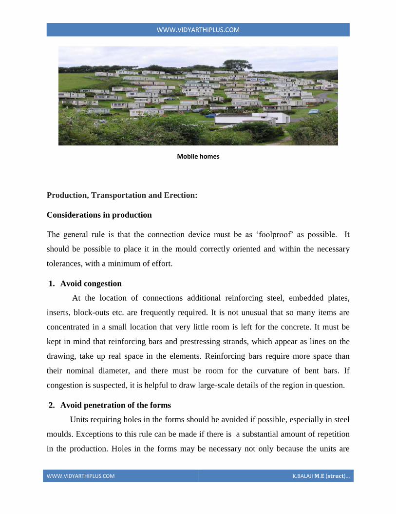
WWWVIDYARTHIPLUSCOM
WWWVIDYARTHIPLUSCOM KBALAJI 119820119812 (119852119853119851119854119836119853)
protruding from the elements but also for the arrangement used to keep the units in place
during casting The units must also be designed so that they do not make the dismantling
of the form impossible without damage to the form Most forms are supposed to be used
more than once Connection units to be placed in the top surface during casting should be
secured against the edges of the mould using purpose made holding devices These
devices are mostly costly make it more difficult to obtain a smooth surface or the
holding device may hamper the placement of concrete or other surface material The
various disadvantages have to be evaluated before selecting the method However if the
same steel plate is placed in the bottom of the form it can be located with great accuracy
as it can be fixed to the bottom directly
3 Reduce post-stripping work
A plant casting operation is most efficient when the product can be taken directly
to the storage area immediately after removal from the form Any operations required
after stripping and before erection such as special cleaning or finishing welding on
projecting hardware etc should be avoided These operations require additional handling
(increased possibility of damage to the elements) extra workspace and added labour
often with skilled trades Sometimes a trade-off is necessary between penetration of the
forms and post-stripping work
4 Use repetitious details
It is very desirable to repeat details as much as possible Similar details should be
identical even ifit results in a slight over-design
5 Use standard items
Hardware items such as inserts studs steel elements etc should be readily
available standard items that are preferably from more than one supplier It also
simplifies fabrication if similar product items are standardised as to size and shape There
is also less chance of error The same principle applies to reinforcing bars embedded
plates etc
WWWVIDYARTHIPLUSCOM
WWWVIDYARTHIPLUSCOM KBALAJI 119820119812 (119852119853119851119854119836119853)
6 Be aware of material limitations
Examples of this are the radius requirements for bending reinforcing bars standard
lengths for
certain sizes of inserts etc
7 Avoid non-standard tolerances
Dimensional tolerances which are specified to be more rigid than industry
standards are difficult to achieve Connections which require close-fitting parts without
provision for adjustment should be avoided as much as possible
8 Allow alternatives
Very often precasters will prefer certain details The producer should be allowed
to use alternative methods or materials provided the design requirements are met
Allowing alternative solutions willoften result in the most economical and best
performing connections
Considerations for transportation
During transportation any units protruding from the concrete element must be
shielded in order not to create a hazard to people Protruding units must be able to
withstand any shocks they can be subjected to during handling Protruding units like
reinforcing bars can in many cases be difficult to handle during transportation For
example a wall panel shall be transported standing at the edge but has reinforcing bars
protruding at the bottom This will make it necessary to build up the support on the
trucks which is costly takes time and makes the load less stable This problem can be
solved by letting the bars protrude from the top of the element but then the total height
may make it difficult to negotiate the underpasses en route The solution may then be to
have the protruding bars replaced by insert and threaded bar to screw in after the element
has been transported to the site
WWWVIDYARTHIPLUSCOM
WWWVIDYARTHIPLUSCOM KBALAJI 119820119812 (119852119853119851119854119836119853)
If protruding units do not create the kind of problems described above because
they do not stick out that much there still may be some difficulties For example corbels
pointing down during transport may necessitate a lot of additional support provisions for
the columns on the trucks The consequence can be a less stable load or decreased
loading capacity of the truck This kind of problem can be solved by making columns
with the corbels in one plane only and then place every second column lsquotop-to-bottomrsquo
on the trucks Otherwise it is also possible to look for a corbel-free solution
Considerations for Erection
To fully realise this benefit of fast erection of a precast structure and to keep the
costs within reasonable limits field connections should be kept simple In order to fulfil
the design requirements it is sometimes necessary to compromise fabrication and
erection simplicity
1 Use connections that are not weather sensitive
Materials such as grout dry pack cast-in-place concrete and epoxies need special
provisions to be placed in cold weather Welding is slower when the ambient temperature
is low If the connections are designed so that these processes must be completed before
erection can continue costly delays may result
2 Stability of the elements
Some elements may require propping shoring bracing or fastening before the
hoist can be unhooked Planning for the fewest quickest and safest possible operations to
be executed before releasing the hoist will greatly facilitate the erection
WWWVIDYARTHIPLUSCOM
WWWVIDYARTHIPLUSCOM KBALAJI 119820119812 (119852119853119851119854119836119853)
3 Stability of the structure
In every stage of the erection process the stability of the structure as a whole must
be planned and assured If not costly additional measures may have to be taken The
type of connection used may play a decisive role in this
4 Be aware of possible different loading conditions during erection
During erection loading conditions can occur which induce stresses or
deformations as well in the precast concrete units as in the connections which are higher
than those under service conditions When designing the connections due consideration
has to be paid to these effects unless special measures are taken during the erection such
as temporary supports etc to prevent such situations
5 Standardize connection types
All connections which serve similar functions within the building should be
standardized as much as possible As workmen become familiar with the procedures
required to make the connection productivity is enhanced and there is less chance for
error
Some types of connections require skilled craftsmen to accomplish for example
welding and post tensioning The fewer of these skilled trades required the more
economical the connection will be
6 Standardize sizes of components
Whenever possible such things as field bolts loose angles etc should be of
common size for all connections This reduces the chance for error and the time required
searching for the proper item
WWWVIDYARTHIPLUSCOM
WWWVIDYARTHIPLUSCOM KBALAJI 119820119812 (119852119853119851119854119836119853)
7 Use connections that are not susceptible to damage in handling
Reinforcing bars steel plates dowels and bolts that project from the precast piece
will often be damaged in handling requiring repair to make them fit especially if they
are of small diameter or thickness
Connection detail that makes erection impossible
Support solution that makes erection impossible
SHEAR WALL
Shear walls are vertical elements of the horizontal force resisting system Shear walls are
constructed to counter the effects of lateral load acting on a structure In residential
construction shear walls are straight external walls that typically form a box which
provides all of the lateral support for the building
Importance of shear wall
WWWVIDYARTHIPLUSCOM
WWWVIDYARTHIPLUSCOM KBALAJI 119820119812 (119852119853119851119854119836119853)
When shear walls are designed and constructed property and they will have the strength
and stiffness to resist the horizontal forces In building construction a rigid vertical
diaphragm capable of transferring lateral forces from exterior walls floors and roofs to
the ground foundation in a direction parallel to their planes Lateral forces caused by
wind earthquake and uneven settlement loads In addition to the weight of structure and
occupants create powerful twisting (torsion) forces These forces can literally tear (shear)
a building apart Reinforcing a frame by attaching or placing a rigid wall inside it
maintains that shape of the frame and prevents rotation at the joints shear walls are
especially important in high-rise building subjected to lateral wind and seismic forces
In the last two decades shear walls became an important part of mid high rise residential
buildings As part of an earthquake resistant building design these walls are placed in
building plans reducing lateral displacements under earthquake loads So shear wall
frame structure are obtained
Shear wall buildings are usually regular in plan and in elevation However in some
buildings lower floors are used for commercial purposes and the buildings are
characterized with larger plan dimensions at those floors
Purpose of constructing shear walls
1 Shear walls are not only designed to resist gravityvertical loads due to its self weight
amp other living moving loads) but they are also designed for lateral loads of
earthquakeswind The walls are structurally integrated with roofsfloors (diaphragms)
and other lateral
2Shear wall structural systems are more stable because their supporting area (Total
cross sectional area of all shear walls) with reference to total plans area of building is
comparatively more unlike in the case of RCC framed structures
3 Walls have to resist the uplift forces caused by the pull of the wind walls have to
resist the shear forces that try to push the walls over walls have to resist the lateral force
of the wind that tries to push the walls in and pull them away from the building
4 Walls floors and roofs to the ground foundation in a direction parallel to their planes
Lateral forces caused by wind earthquake and uneven settlement loads In addition to the
weight of structure and occupants create powerful twisting (torsion) forces These forces
can literally tear (shear) a building apart Reinforcing a frame by attaching or placing a
WWWVIDYARTHIPLUSCOM
WWWVIDYARTHIPLUSCOM KBALAJI 119820119812 (119852119853119851119854119836119853)
rigid wall inside it maintain the joints shear walls are especially important in high-rise
building subjected to lateral wind and seismic forces
In the last two decades shear walls became as important part of mid high rise residential
buildings As part of an earthquake resistant building design these walls are placed in
building plans reducing lateral displacements under earthquake loads So shear wall
frame structures are obtained
Shear wall buildings are usually regular in plan and in elevation However in some
buildings lower floors are used for commercial purposes and the buildings are
characterized with larger plan dimensions at these floors
Comparisons of shear wall with construction of conventional load bearing walls
Load bearing masonry is very brittle material Due to different kinds of stresses such as
shear tensileetc Caused by the earthquakes the conventional unreinforced brick
masonry collapses instantly during the unpredictable and sudden earthquakes
The RCC framed structures are slender When compared to shear wall concept of box
like three-dimensional structures though it is possible to design the earthquake resistant
RCC frame it requires extra-ordinary skills at design detailing and construction levels
Which cannot be anticipated in all types of construction projects
On the other hand even moderately designed shear wall structures not only more stable
but also comparatively quite ductile In safety terms it means that during very severe
earthquakes they will not suddenly collapse causing death of people They give enough
indicative warnings such as widening structural cracks yielding rods etc offering most
precious moment for people to run out off structures before they totally collapse
For structural purposes we consider the exterior walls as the shear resisting walls Forces
from the ceiling and roof diaphragms make their way to the outside along assumed paths
enter the walls and exit at the foundation
Forces on shear wall
Shear wall resist two types of forces
1 Shear forces
2 Uplift forces
Shear Forces
Shear forces are generated in stationary buildings by accelerations resulting from ground
movement and by external forces like wind amp waves This action creates shear forces
throughout the height of the wall between the top and bottom shear wall connections
Uplift Forces
WWWVIDYARTHIPLUSCOM
WWWVIDYARTHIPLUSCOM KBALAJI 119820119812 (119852119853119851119854119836119853)
Uplift forces exist on shear walls because the horizontal forces are applied to the top of
the wall These uplift forces try to lift up one end of the wall and push the other end
down In some cases the uplift force is large enough to tip the wall over Uplift forces are
greater on tall short walls uplift shear walls need hold down devices at each end when the
gravity loads cannot resist all of the uplift The hold down device then provides the
necessary uplift resistance
Classification of shear walls
1 Simple rectangular types amp flanged walls
2 Coupled shear walls
3 Rigid frame shear walls
4 Framed walls with in filled frames
5 Column supported shear walls
6 Core type shear walls
Types of shear walls
1 RC shear wall
2 Plywood shear wall
3 Mid ply shear wall
WWWVIDYARTHIPLUSCOM
WWWVIDYARTHIPLUSCOM KBALAJI 119820119812 (119852119853119851119854119836119853)
4 RC Hollow concrete Block masonry wall
5 Steel plate shear wall
RC shear wall
It consists of reinforced concrete walls and reinforced concrete slabs wall thickness varies
from 140 mm to 500 mm depending on the number of stories building age and thermal
insulation requirement In general these walls are continuous throughout the building
height however Some walls are discontinued as the steel front or basement level to allow
for commercial or parking spaces Floors slabs are either cast in-situ flat slabs or less
often Precast hollow core slabs Buildings are supported by concrete strip or mat
foundations the latter type is common for buildings with basements
Ply wood shear wall
Plywood is the traditional material used in the construction of shear walls the creation of
pre-fabricated shear panels have made it possible to inject strong shear assemblies into
small walls that fall at either side of a opening in a shear wall plywood shear wall consist
of
o Plywood to transfer shear forces
o Chords to resist tensioncompression generated by the over turning
moments
o Base connections to transfer shear to foundations
Midply shear wall
The midply shear wall is an improved timber shear wall that was developed by
redesigning the joints between shearing and finishing members So that the failure modes
observed in standard wall testing are virtually eliminated at lateral loads levels high
enough to cause failures in standard walls
RC Hollow concrete block masonry walls (RHCBM)
These walls are constructed by reinforcing the hollow concrete block masonry by taking
advantage of hollow spaces amp shapes of the hollow blocks It requires continuous steel
rods (reinforcement) both in the vertical amp horizontal directions at structurally critical
locations of the wall panels packed with the fresh grout concrete in the hollow spaces of
masonry bocks
RHCBC elements are designed both as load bearing walls for gravity loads and also as
shear walls for lateral seismic loads to safety withstand earthquakes
Steel plate shear wall
In general steel plate shear wall system consists of a steel plate wall boundary columns
and horizontal floor beams Together the steel plate wall and boundary columns act as a
vertical plate girder The column act as flanges of the vertical plate girder and the steel
WWWVIDYARTHIPLUSCOM
WWWVIDYARTHIPLUSCOM KBALAJI 119820119812 (119852119853119851119854119836119853)
plates wall act as its web The horizontal floor beams act more or less as transverse
stiffeners in a plate girder steel plate shear wall systems have been used in recent years in
highly seismic area to resist lateral loads
Thus shear walls are one of the most effective building elements in resisting lateral forces
during earthquake By constructing shear walls damages due to effect of lateral forces
due to earthquake and high winds can be minimized shear walls construction will provide
larger stiffness to the buildings there by reducing the damage to structure and its contents
Hence it is preferable to have all these prefabricate approximately of some weight very
near to the lifting capacity of the equipment
SHEAR WALL
WWWVIDYARTHIPLUSCOM
WWWVIDYARTHIPLUSCOM KBALAJI 119820119812 (119852119853119851119854119836119853)
WWWVIDYARTHIPLUSCOM
WWWVIDYARTHIPLUSCOM KBALAJI 119820119812 (119852119853119851119854119836119853)
WWWVIDYARTHIPLUSCOM
WWWVIDYARTHIPLUSCOM KBALAJI 119820119812 (119852119853119851119854119836119853)
Off-site fabrication
Off-Site fabrication is a process that incorporates prefabrication and pre-assembly The
process involves the design and manufacture of units or modules usually remote from the
work site and the installation at the site to form the permanent works at the site In its
fullest sense off-site fabrication requires a project strategy that will change the
orientation of the project process from construction to manufacture to installation
Examples of off-site fabrication are wall panels for homes wooden truss bridge spans
airport control stations
There are 4 main categories of Off-Site fabrication which is often also referred to as Off-
Site Construction These can be described as component (or sub-assembly) systems
penalized systems volumetric systems and modular systems Below these categories
different branches or technologies are being developed There are a vast number of
different systems on the market which fall into these categories and with recent advances
in digital design such as Building Information Modeling (BIM) the task of integrating
WWWVIDYARTHIPLUSCOM
WWWVIDYARTHIPLUSCOM KBALAJI 119820119812 (119852119853119851119854119836119853)
these different systems into a construction project is becoming increasingly a digital
management proposition
Unit -1
Question with answer
Part-A-
1Define prefabrication
The term prefab can apply to any construction method where the significant part of the
construction takes place off site in a factory That produces relatively large complex
features that assembled at the site into the finished building
2What is meant by modular Coordination
Modular coordination is a concept for coordinating dimension and space for which
building and component are dimensionally it used and positioned in basic units (or)
modules
The standard specify that the module basic M = 100 mm As the basic unit be used in a
square of M
3What are the characteristics of Modular concept
I) The basic module is small in terms of add size in order to provide design flexibility
yet large enough to promote simplification in the component variation in sizes
II) Industry friendly features that not only for manufacturing but also the transportation
and assembly requirements
III) Internationally accepted to support international market
4 Write out the advantages amp disadvantages of prefabrication
I) Self supporting readymade components are used so the need for formwork shuttering
and scaffolding is greatly reduced
II) On-site construction and condition is minimized
III) Less waste may occur
Disadvantages
I)Careful handling of prefabricated components such as concrete panels (or) steel and
glass Panels is reduced
II) Similarly leaks can form at joints is prefabricated component
5) Define the term Off-site fabrication
WWWVIDYARTHIPLUSCOM
WWWVIDYARTHIPLUSCOM KBALAJI 119820119812 (119852119853119851119854119836119853)
Off-site fabrication is the process that incorporates prefabrication and preassemble the
process involves the design and manufacture of units usually remote from the work site
and the installation at the site to form the permanent work at the site
6) Write short note on Production process
The production of concrete blocks consists of four basic process They are
1) Mixing
2) Moulding
3) Curing
4) Cubing
7) List out the limitations of prefabrication
I) Extra reinforcement is required to take care of handling and erection stresses
II) Temporary props may be required in some cases before the un-site concrete joints
achieve strength
III) The cracks may develop at the joints between the precart in ndashsite concrete due to
shrinkage and temperature stresses To overcome them extra steel is required across
joint
8) What are all the Prefab materials
Structural insulated panels (SIPs)
Insulating concrete forms (ICFS)
Prefab foundation system
Steel framing
Concrete framing
Large - modular system
9) Insulating concrete forms
Insulating concrete forms (ICE) are a prefab construction material consisting of hollow
EPS foam blocks that are stacked and glued together on-site creating the form that is
filled with reinforcing bars and concrete
10) Write short note on Principles of MC Concept
The principle objective of implanting MC is to improve productivity through the
reduction of wastages in the production installation process to improve quality in the
construction industry and to encourage an open system
WWWVIDYARTHIPLUSCOM
WWWVIDYARTHIPLUSCOM KBALAJI 119820119812 (119852119853119851119854119836119853)
11 Define shear wall
These are simple type and these shear walls under forces and horizontal shear along its
length are subjected to bending and shear To resist these forces the uniform
distribution of steel along its length is used in simple shear walls
12 Different classification of shear walls
1) Plain rectangular shear wall
2) Bar bell type
3) Framed shear wall
4) Coupled shear wall
5) Care type
13What is Modular Coordination
Modular coordination or MC is a dimensional system It is a dimension and space
coordination concept in which building and components are placed at their
designations based on the unit
14 How dimensional coordination is helpful in prefabricated structures
Building production is the organization and management of the plans equipment
materials and labour involved in the construction of a building while at the same time
complying with all codes rules and contractual stipulations The procedure should be
designed to run efficiently to keep the costs low and to allow returns on the
investment to be realized as early as possible
15 Explain the term basic module
Modular are terms that usually refer to upscale housing that can be any combination
of pre-engineered home parts that re delivered to the building site ready to be
assembled in a quick manner
16 What are the factors to consider in transporting of prefabricated structures
Transport device being movable from the input end to the output end of the production
line through a series of workstations said building unit being fabricated on an upper
surface of said flatbed said flatbed having an anti-friction surface on the upper surface
WWWVIDYARTHIPLUSCOM
WWWVIDYARTHIPLUSCOM KBALAJI 119820119812 (119852119853119851119854119836119853)
thereof for permitting sliding movement of said building unit relative to said transport
device
17 Explain the role of shear connectors in pre fabricated structures
Shear connectors may be spaced uniformly between the sections of maximum and zero
moment Shear connectors should have at least 1 in (254 mm) of concrete cover in all
directions and unless studs are located directly over the web stud diameters may not
exceed 25 times the beam-flange thickness With heavy concentrated loads the uniform
spacing of shear connectors may not be sufficient between a concentrated load and the
nearest point of zero moment
18 What are the special material properties in of prefabricated structures
Quicktoassemble
Cost-effective
Portablemovable
Strong
Water proof Moisture proof
Fire Resistant
19 What are the types of shear walls
Vertical Offset of Shear Walls
Stiffness shear wall
Steel shear wall
20 Write short notes on prefabrication
Prefabrication is the practice of assembling components of a structure in a factory or
other manufacturing site and transporting complete assemblies or sub-assemblies to
the construction site where the structure is to be located prefabrication in
architectural construction a technique whereby large units of a building are produced
WWWVIDYARTHIPLUSCOM
WWWVIDYARTHIPLUSCOM KBALAJI 119820119812 (119852119853119851119854119836119853)
in factories to be assembled ready-made on the building site The technique permits
the speedy erection of very large structures
21 Write any two advantages of prefabrication construction
Self-supporting ready-made components are used so the need for formwork
shuttering and scaffolding is greatly reduced
Construction time is reduced and buildings are completed sooner allowing an
earlier return of the capital invested
22 Define the term module
23 Write short notes on shear wall
A shear wall is a wall which is designed to resist shear the lateral force which causes
the bulk of damage in earthquakes
24 Write any two prefabrication problem of materials
Non availability of materials
Economy
25 Write the types of Derricks
A derrick is a lifting device composed of one mast or pole which is hinged freely at
the bottom It is controlled by lines powered by some means such as man-hauling or
motors so that the pole can move in all four directions
Hallen Derrick
Velle Derrick
Stuumllcken Derrick
26 What are the advantages of prefabricated structures
WWWVIDYARTHIPLUSCOM
WWWVIDYARTHIPLUSCOM KBALAJI 119820119812 (119852119853119851119854119836119853)
On-site construction and congestion is minimized
Quality control can be easier in a factory assembly line setting than a construction
site setting
Prefabrication can be located where skilled labour is more readily available and
costs of labour power materials space and overheads are lower
Time spent in bad weather or hazardous environments at the construction site is
minimised
27 What are the safety factors to be considered in designing
28 Explain about the location of shear wall
Lateral forces caused by wind earthquake and uneven settlement loads in addition to
the weight of structure and occupants create powerful twisting (torsional) forces
These forces can literally tear (shear) a building apart Reinforcing a frame by
attaching or placing a rigid wall inside it maintains the shape of the frame and
prevents rotation at the joints Shear walls are especially important in high-rise
buildings subject to lateral wind and seismic forces
29 What are the lateral loads in a building Live load
Wind load
Earthquake load 30What are the lateral load resisting elements in a building (AUC NovDec 2013) Vertical Elements
Moment
Resisting Frames
Walls
Bearing walls Shear Walls Structural Walls
Gravity Frame + Walls
ldquoDualrdquo System (Frame + Wall)
WWWVIDYARTHIPLUSCOM
WWWVIDYARTHIPLUSCOM KBALAJI 119820119812 (119852119853119851119854119836119853)
Vertical Truss
Tube System
Bundled
Tube System FloorDiaphragm
Foundation
WWWVIDYARTHIPLUSCOM
WWWVIDYARTHIPLUSCOM KBALAJI 119820119812 (119852119853119851119854119836119853)
Part-B
1Explain Modular Coordination in detail
Modular coordination means the interdependent arrangement of a dimension based on a
primary value accepted as a module The strict observance of rules of modular
coordination facilitated
1 Assembly of single components into large components
2 Fewest possible different types of component
3 Minimum wastage of cutting needed
Modular coordination is the basis for a standardization of a mass production of
component A
set of rules would be adequate for meeting the requirements of conventional and
prefabricated construction These rules are adaptable for
a The planning grid in both directions of the horizontal plan shall be
1 3M for residential and institutional buildings
2 For industrial buildings
WWWVIDYARTHIPLUSCOM
WWWVIDYARTHIPLUSCOM KBALAJI 119820119812 (119852119853119851119854119836119853)
15M for spans up to 12m
30M for spans between 12m and 18m
60M for spans over 18m
The centre lines of load bearing walls shall coincide with the grid lines
b In case of external walls the grid lines shall coincide with the centre line of the wall or
a line on the wall 5 cm from the internal face of the wall
C The planning module in the vertical direction shall be 1M up to and including a ht of
28M
d Preferred increments for the still heights doors windows and other fenestration shall
be
1M
e In case of internal columns the grid lines shall coincide with the centre lines of
columns In case of external columns the grid lines shall coincide with the centre lines of
the columns in the storey or a line in the column from the internal face of the column in
the topmost storey A basic module can be represented as module and for larger project
modules are represented a Mp
For eg For a project module in horizontal coordination the component can be of 30cm
and for vertical component size be of 10cm
The storey height is fixed between finished floor levels as 28m and if the thickness of
slab is lt15cm storey height is fixed as 27m The centre distance between the load
bearing walls can be chose from a set of modules The use of other dimensions is not
allowed
In the design of a building modular grid can be used consisting of parallel line spaced at
a value of module M or Mp and a grid line chosen as a base for setting out a part of a
building becomes a modular axis In the fig (a) a typical grid is chosen for load bearing
walls without duct The interior walls are placed so that their centre lines coincide with
the modular axis In the fig (b) a grid is shown for load bearing walls with hollow ducts
in between The centre line of the grid is found by deducting the size of duct
WWWVIDYARTHIPLUSCOM
WWWVIDYARTHIPLUSCOM KBALAJI 119820119812 (119852119853119851119854119836119853)
2Systems of prefabrication
System is referred to a particular method of construction of buildings using the
prefabricated components which are inter related in functions and are produced to a set of
instructions With certain constraints several plans are possible using the same set of
components the degree of flexibility varies from system to system However in all the
systems there is a certain order and discipline The system of prefabricated construction
depends on the extend of the use of prefab components their characteristics to be
considered in devising a system
i Intensified usage of spaces
ii Straight and simple walling scheme
iii Limited sizes and numbers of components
iv Limited opening in bearing walls
v Regulated locations of partitions
vi Standardized service and stair units
vii Limited sizes of doors and windows with regulated positions
viii Structural clarity and efficiency
ix Suitability for adoption in low rise and high rise blocks
x Ease of manufacturing storing and transporting
xi Speed and ease of erection
xii Simple jointing system
a) Based on Disuniting of member
b) Based on the construction
WWWVIDYARTHIPLUSCOM
WWWVIDYARTHIPLUSCOM KBALAJI 119820119812 (119852119853119851119854119836119853)
Based on Disuniting of member
1 System consisting of linear member disunited at joints
2 System for prefabricates of entire rigid frame
3 System consisting of ITU of straight members disunited at points of minimum
moment
4 Two hinged and three hinged arches
System consisting of linear member disunited at joints
Advantage
Disuniting at joints gives linear member This means that a great advantage and facilitates
from the view point manufacture and assembly
Disadvantage
1 Joints are at corners ie at points of maximum moment values so forming the joint is
difficult
2 Joints must be over dimensioned to cope with in-situ concreting And one alternate
solution to replace moment resistant joints by hinged connection
System for prefabricates of entire rigid frame
WWWVIDYARTHIPLUSCOM
WWWVIDYARTHIPLUSCOM KBALAJI 119820119812 (119852119853119851119854119836119853)
In this system to reduce the no of joints and to precast larger numbers I one piece leads
to the prefabrication of entire frame Production of the frames does not cause any
particular trouble but the hoisting is more difficult and requires careful preparation The
stress distribution of straight members during hoisting is in general statistically
determinate
Advantage
1 It is ideal for site prefabrication
2 Small number of joints so rapid prefabrication work is possible
3 Suitable for long walls consisting of great number of uniform frames
System consisting of ITU of straight members disunited at points of minimum
moment
WWWVIDYARTHIPLUSCOM
WWWVIDYARTHIPLUSCOM KBALAJI 119820119812 (119852119853119851119854119836119853)
WWWVIDYARTHIPLUSCOM
WWWVIDYARTHIPLUSCOM KBALAJI 119820119812 (119852119853119851119854119836119853)
Another method of disuniting of structures is by division into different membranes at
points where the moments are thin or smallest This method is called as lambda method
Using this method hinge joints are made
Advantage
1 Functions are made at points of minimum moments or at points of contra flexure
2 Disuniting the main girder in this manner makes the application of different skylights
possible
Disadvantage
1 Hosting and temperature bracing of L joined asymmetric frame members is
WWWVIDYARTHIPLUSCOM
WWWVIDYARTHIPLUSCOM KBALAJI 119820119812 (119852119853119851119854119836119853)
particularly complicated
2 Temperature resting of frame member on each other necessitates the use of
cantilevers having half depth and proper forming of this cause difficulty
Two hinged and three hinged arches
Arched structures are normally two hinged and three hinged arches Arched structures are
normally used for bridging span more than 20-25m Their production and placing is more
difficult than straight members Arch can be two hinged and three hinged but they can
also be fixed at footings and can be constructed with or without tie
These members are generally precast and assembled in statistically determinant three
hinged variance and middle hinge is only eliminated after placing is finished The
reinforcing bars protruding both sides are welded together and the joint between the
members is filled in with insitu concrete
Arch structure can be precast in either vertical or horizontal positions In the first case
shuttering made of timber or concrete is required having the same curvature s the arch
itself
The prefabrication of larger arches in the horizontal position is found to be more
economical
The construction of arch trusses can be properly carried out in the horizontal position
only
WWWVIDYARTHIPLUSCOM
WWWVIDYARTHIPLUSCOM KBALAJI 119820119812 (119852119853119851119854119836119853)
3Methods of prefabrication
Site prefabrication- for large prefabricates
Plant prefabrication- large scale production
Site prefabrication
1 The RC members are produced t the site in the open air chiefly in the open air or in
the temporary sheds
2 The difficulties in construction in general are felt in this mechanization can case
3 Mechanization cannot be of such high degree as site PF is done for smaller duration
of time
4 When the pre fabricates are of large size it is difficult to transport the pre fabricates to
the site
5 In comparison with plant prefabrication transportation of the members are not needed
As large members are not transported the design and weight of the prefabricates are not
limited
Plant prefabrication
1 The members produced are to be transported t the place of construction this accounts
for about 10-15 of the cost of production and assembling
2 Certain restriction is made in the dimension of prefabrication leading to restraints in
the design and development of prefabrication
3 Prefabrication is appropriate for mass production for manufacture of standardized
members
4 Needs costly materials for batching and production
5 This method is most suited in the case of small prefabricates which are to be
prefabricated in very large number
Plant prefabrication is done under permanent plant or factories It is done under the
covered roof so the effect of weather does not affect the work So the quality and strength
of the members can be improved considerably Plant prefabrication reduces the cost of
prefabrication if the number of prefabricate needed is more
Dimensions of prefabricate
There are 3 commonly known dimension for the prefabricates
1 The design of the erection dimension governing the dimensional coordination of the
prefabricates
2 Theoretical dimension
3 The actual dimension of the element when delivered the design dimension should be a
multiple of a basic module size m or of a module lap
WWWVIDYARTHIPLUSCOM
WWWVIDYARTHIPLUSCOM KBALAJI 119820119812 (119852119853119851119854119836119853)
Production of prefabricates
Production techniques involved are
1 Stand method
2 Conveyor method or line method
3 Aggregate method
Stand Method
In this method the prefabrication mature where they are moulded while the production
teams moves to successive stands The bed on which prefabricates are cast may be fixed
or
movable Tilting forms are often used and in this method steam curing is generally done
Conveyor belt method
The whole production is split up in to series operations carried out at separate successive
and permanent points served by specialized teams The movement of the mould or
prefabricate one point to other vary by means of conveyor belt trolleys
The rigid steel forms are assembled at station 1 where they are mould oil to reduce the
adhesion of concrete The conveyor moves front 1 to 2 where prestressing wires are fixed
amp in the next station anchoring of the wires is carried out The prepared mould is then
carried to the station 1ie casting station After casting it is shifted to the vibrating table amp
finally stacked station 5 for setting After that it is passed through tunnel autoclave for
curing After steam curing move too station 7 for demoulding amp is finally stacked 8
Aggregate method
In the aggregate method aggregate describes large complex permanently installed
machines amp mechanical appliances which carry out most of the separate operations
involved in the casting of the concrete composition The stand is operated by a permanent
team amp the only move the prefabricate makes is to the maturing point
Aggregate method is used in the production of multi duct hollow floor panel in Poland
At production point the reinforcement is fixed in the form amp remote controlled
aggregate(machine)inserts the duct formers castamp vibrates the concrete floats the top
of the floor The prepared prefabricate then move to the autoclave chamber in which
hardening of concrete is accelerate In many factories combined technology are employed
when complex prefabricate are required
Advantages
1The stand technique is the most flexible one It is used in varying degrees of
mechanization in all kinds of prefabricate factories
2It is simple amp less capital is required It can be used for field prefabricate also
WWWVIDYARTHIPLUSCOM
WWWVIDYARTHIPLUSCOM KBALAJI 119820119812 (119852119853119851119854119836119853)
3Aggregate method is used for large scale production in which case number of
machineries is required
4 Explain specific requirements in layout of of prefabricated plants
WWWVIDYARTHIPLUSCOM
WWWVIDYARTHIPLUSCOM KBALAJI 119820119812 (119852119853119851119854119836119853)
WWWVIDYARTHIPLUSCOM
WWWVIDYARTHIPLUSCOM KBALAJI 119820119812 (119852119853119851119854119836119853)
5 Explain with neat sketch of the types of shear wall
WWWVIDYARTHIPLUSCOM
WWWVIDYARTHIPLUSCOM KBALAJI 119820119812 (119852119853119851119854119836119853)
WWWVIDYARTHIPLUSCOM
WWWVIDYARTHIPLUSCOM KBALAJI 119820119812 (119852119853119851119854119836119853)
6 What is the code use for prefabricated structures
WWWVIDYARTHIPLUSCOM
WWWVIDYARTHIPLUSCOM KBALAJI 119820119812 (119852119853119851119854119836119853)
7 Explain in detail various design consideration in the design of precast construction
WWWVIDYARTHIPLUSCOM
WWWVIDYARTHIPLUSCOM KBALAJI 119820119812 (119852119853119851119854119836119853)
WWWVIDYARTHIPLUSCOM
WWWVIDYARTHIPLUSCOM KBALAJI 119820119812 (119852119853119851119854119836119853)
3 Stability of the structure
In every stage of the erection process the stability of the structure as a whole must
be planned and assured If not costly additional measures may have to be taken The
type of connection used may play a decisive role in this
4 Be aware of possible different loading conditions during erection
During erection loading conditions can occur which induce stresses or
deformations as well in the precast concrete units as in the connections which are higher
than those under service conditions When designing the connections due consideration
has to be paid to these effects unless special measures are taken during the erection such
as temporary supports etc to prevent such situations
5 Standardize connection types
All connections which serve similar functions within the building should be
standardized as much as possible As workmen become familiar with the procedures
required to make the connection productivity is enhanced and there is less chance for
error
Some types of connections require skilled craftsmen to accomplish for example
welding and post tensioning The fewer of these skilled trades required the more
economical the connection will be
6 Standardize sizes of components
Whenever possible such things as field bolts loose angles etc should be of
common size for all connections This reduces the chance for error and the time required
searching for the proper item
WWWVIDYARTHIPLUSCOM
WWWVIDYARTHIPLUSCOM KBALAJI 119820119812 (119852119853119851119854119836119853)
7 Use connections that are not susceptible to damage in handling
Reinforcing bars steel plates dowels and bolts that project from the precast piece
will often be damaged in handling requiring repair to make them fit especially if they
are of small diameter or thickness
Connection detail that makes erection impossible
Support solution that makes erection impossible
SHEAR WALL
Shear walls are vertical elements of the horizontal force resisting system Shear walls are
constructed to counter the effects of lateral load acting on a structure In residential
construction shear walls are straight external walls that typically form a box which
provides all of the lateral support for the building
Importance of shear wall
WWWVIDYARTHIPLUSCOM
WWWVIDYARTHIPLUSCOM KBALAJI 119820119812 (119852119853119851119854119836119853)
When shear walls are designed and constructed property and they will have the strength
and stiffness to resist the horizontal forces In building construction a rigid vertical
diaphragm capable of transferring lateral forces from exterior walls floors and roofs to
the ground foundation in a direction parallel to their planes Lateral forces caused by
wind earthquake and uneven settlement loads In addition to the weight of structure and
occupants create powerful twisting (torsion) forces These forces can literally tear (shear)
a building apart Reinforcing a frame by attaching or placing a rigid wall inside it
maintains that shape of the frame and prevents rotation at the joints shear walls are
especially important in high-rise building subjected to lateral wind and seismic forces
In the last two decades shear walls became an important part of mid high rise residential
buildings As part of an earthquake resistant building design these walls are placed in
building plans reducing lateral displacements under earthquake loads So shear wall
frame structure are obtained
Shear wall buildings are usually regular in plan and in elevation However in some
buildings lower floors are used for commercial purposes and the buildings are
characterized with larger plan dimensions at those floors
Purpose of constructing shear walls
1 Shear walls are not only designed to resist gravityvertical loads due to its self weight
amp other living moving loads) but they are also designed for lateral loads of
earthquakeswind The walls are structurally integrated with roofsfloors (diaphragms)
and other lateral
2Shear wall structural systems are more stable because their supporting area (Total
cross sectional area of all shear walls) with reference to total plans area of building is
comparatively more unlike in the case of RCC framed structures
3 Walls have to resist the uplift forces caused by the pull of the wind walls have to
resist the shear forces that try to push the walls over walls have to resist the lateral force
of the wind that tries to push the walls in and pull them away from the building
4 Walls floors and roofs to the ground foundation in a direction parallel to their planes
Lateral forces caused by wind earthquake and uneven settlement loads In addition to the
weight of structure and occupants create powerful twisting (torsion) forces These forces
can literally tear (shear) a building apart Reinforcing a frame by attaching or placing a
WWWVIDYARTHIPLUSCOM
WWWVIDYARTHIPLUSCOM KBALAJI 119820119812 (119852119853119851119854119836119853)
rigid wall inside it maintain the joints shear walls are especially important in high-rise
building subjected to lateral wind and seismic forces
In the last two decades shear walls became as important part of mid high rise residential
buildings As part of an earthquake resistant building design these walls are placed in
building plans reducing lateral displacements under earthquake loads So shear wall
frame structures are obtained
Shear wall buildings are usually regular in plan and in elevation However in some
buildings lower floors are used for commercial purposes and the buildings are
characterized with larger plan dimensions at these floors
Comparisons of shear wall with construction of conventional load bearing walls
Load bearing masonry is very brittle material Due to different kinds of stresses such as
shear tensileetc Caused by the earthquakes the conventional unreinforced brick
masonry collapses instantly during the unpredictable and sudden earthquakes
The RCC framed structures are slender When compared to shear wall concept of box
like three-dimensional structures though it is possible to design the earthquake resistant
RCC frame it requires extra-ordinary skills at design detailing and construction levels
Which cannot be anticipated in all types of construction projects
On the other hand even moderately designed shear wall structures not only more stable
but also comparatively quite ductile In safety terms it means that during very severe
earthquakes they will not suddenly collapse causing death of people They give enough
indicative warnings such as widening structural cracks yielding rods etc offering most
precious moment for people to run out off structures before they totally collapse
For structural purposes we consider the exterior walls as the shear resisting walls Forces
from the ceiling and roof diaphragms make their way to the outside along assumed paths
enter the walls and exit at the foundation
Forces on shear wall
Shear wall resist two types of forces
1 Shear forces
2 Uplift forces
Shear Forces
Shear forces are generated in stationary buildings by accelerations resulting from ground
movement and by external forces like wind amp waves This action creates shear forces
throughout the height of the wall between the top and bottom shear wall connections
Uplift Forces
WWWVIDYARTHIPLUSCOM
WWWVIDYARTHIPLUSCOM KBALAJI 119820119812 (119852119853119851119854119836119853)
Uplift forces exist on shear walls because the horizontal forces are applied to the top of
the wall These uplift forces try to lift up one end of the wall and push the other end
down In some cases the uplift force is large enough to tip the wall over Uplift forces are
greater on tall short walls uplift shear walls need hold down devices at each end when the
gravity loads cannot resist all of the uplift The hold down device then provides the
necessary uplift resistance
Classification of shear walls
1 Simple rectangular types amp flanged walls
2 Coupled shear walls
3 Rigid frame shear walls
4 Framed walls with in filled frames
5 Column supported shear walls
6 Core type shear walls
Types of shear walls
1 RC shear wall
2 Plywood shear wall
3 Mid ply shear wall
WWWVIDYARTHIPLUSCOM
WWWVIDYARTHIPLUSCOM KBALAJI 119820119812 (119852119853119851119854119836119853)
4 RC Hollow concrete Block masonry wall
5 Steel plate shear wall
RC shear wall
It consists of reinforced concrete walls and reinforced concrete slabs wall thickness varies
from 140 mm to 500 mm depending on the number of stories building age and thermal
insulation requirement In general these walls are continuous throughout the building
height however Some walls are discontinued as the steel front or basement level to allow
for commercial or parking spaces Floors slabs are either cast in-situ flat slabs or less
often Precast hollow core slabs Buildings are supported by concrete strip or mat
foundations the latter type is common for buildings with basements
Ply wood shear wall
Plywood is the traditional material used in the construction of shear walls the creation of
pre-fabricated shear panels have made it possible to inject strong shear assemblies into
small walls that fall at either side of a opening in a shear wall plywood shear wall consist
of
o Plywood to transfer shear forces
o Chords to resist tensioncompression generated by the over turning
moments
o Base connections to transfer shear to foundations
Midply shear wall
The midply shear wall is an improved timber shear wall that was developed by
redesigning the joints between shearing and finishing members So that the failure modes
observed in standard wall testing are virtually eliminated at lateral loads levels high
enough to cause failures in standard walls
RC Hollow concrete block masonry walls (RHCBM)
These walls are constructed by reinforcing the hollow concrete block masonry by taking
advantage of hollow spaces amp shapes of the hollow blocks It requires continuous steel
rods (reinforcement) both in the vertical amp horizontal directions at structurally critical
locations of the wall panels packed with the fresh grout concrete in the hollow spaces of
masonry bocks
RHCBC elements are designed both as load bearing walls for gravity loads and also as
shear walls for lateral seismic loads to safety withstand earthquakes
Steel plate shear wall
In general steel plate shear wall system consists of a steel plate wall boundary columns
and horizontal floor beams Together the steel plate wall and boundary columns act as a
vertical plate girder The column act as flanges of the vertical plate girder and the steel
WWWVIDYARTHIPLUSCOM
WWWVIDYARTHIPLUSCOM KBALAJI 119820119812 (119852119853119851119854119836119853)
plates wall act as its web The horizontal floor beams act more or less as transverse
stiffeners in a plate girder steel plate shear wall systems have been used in recent years in
highly seismic area to resist lateral loads
Thus shear walls are one of the most effective building elements in resisting lateral forces
during earthquake By constructing shear walls damages due to effect of lateral forces
due to earthquake and high winds can be minimized shear walls construction will provide
larger stiffness to the buildings there by reducing the damage to structure and its contents
Hence it is preferable to have all these prefabricate approximately of some weight very
near to the lifting capacity of the equipment
SHEAR WALL
WWWVIDYARTHIPLUSCOM
WWWVIDYARTHIPLUSCOM KBALAJI 119820119812 (119852119853119851119854119836119853)
WWWVIDYARTHIPLUSCOM
WWWVIDYARTHIPLUSCOM KBALAJI 119820119812 (119852119853119851119854119836119853)
WWWVIDYARTHIPLUSCOM
WWWVIDYARTHIPLUSCOM KBALAJI 119820119812 (119852119853119851119854119836119853)
Off-site fabrication
Off-Site fabrication is a process that incorporates prefabrication and pre-assembly The
process involves the design and manufacture of units or modules usually remote from the
work site and the installation at the site to form the permanent works at the site In its
fullest sense off-site fabrication requires a project strategy that will change the
orientation of the project process from construction to manufacture to installation
Examples of off-site fabrication are wall panels for homes wooden truss bridge spans
airport control stations
There are 4 main categories of Off-Site fabrication which is often also referred to as Off-
Site Construction These can be described as component (or sub-assembly) systems
penalized systems volumetric systems and modular systems Below these categories
different branches or technologies are being developed There are a vast number of
different systems on the market which fall into these categories and with recent advances
in digital design such as Building Information Modeling (BIM) the task of integrating
WWWVIDYARTHIPLUSCOM
WWWVIDYARTHIPLUSCOM KBALAJI 119820119812 (119852119853119851119854119836119853)
these different systems into a construction project is becoming increasingly a digital
management proposition
Unit -1
Question with answer
Part-A-
1Define prefabrication
The term prefab can apply to any construction method where the significant part of the
construction takes place off site in a factory That produces relatively large complex
features that assembled at the site into the finished building
2What is meant by modular Coordination
Modular coordination is a concept for coordinating dimension and space for which
building and component are dimensionally it used and positioned in basic units (or)
modules
The standard specify that the module basic M = 100 mm As the basic unit be used in a
square of M
3What are the characteristics of Modular concept
I) The basic module is small in terms of add size in order to provide design flexibility
yet large enough to promote simplification in the component variation in sizes
II) Industry friendly features that not only for manufacturing but also the transportation
and assembly requirements
III) Internationally accepted to support international market
4 Write out the advantages amp disadvantages of prefabrication
I) Self supporting readymade components are used so the need for formwork shuttering
and scaffolding is greatly reduced
II) On-site construction and condition is minimized
III) Less waste may occur
Disadvantages
I)Careful handling of prefabricated components such as concrete panels (or) steel and
glass Panels is reduced
II) Similarly leaks can form at joints is prefabricated component
5) Define the term Off-site fabrication
WWWVIDYARTHIPLUSCOM
WWWVIDYARTHIPLUSCOM KBALAJI 119820119812 (119852119853119851119854119836119853)
Off-site fabrication is the process that incorporates prefabrication and preassemble the
process involves the design and manufacture of units usually remote from the work site
and the installation at the site to form the permanent work at the site
6) Write short note on Production process
The production of concrete blocks consists of four basic process They are
1) Mixing
2) Moulding
3) Curing
4) Cubing
7) List out the limitations of prefabrication
I) Extra reinforcement is required to take care of handling and erection stresses
II) Temporary props may be required in some cases before the un-site concrete joints
achieve strength
III) The cracks may develop at the joints between the precart in ndashsite concrete due to
shrinkage and temperature stresses To overcome them extra steel is required across
joint
8) What are all the Prefab materials
Structural insulated panels (SIPs)
Insulating concrete forms (ICFS)
Prefab foundation system
Steel framing
Concrete framing
Large - modular system
9) Insulating concrete forms
Insulating concrete forms (ICE) are a prefab construction material consisting of hollow
EPS foam blocks that are stacked and glued together on-site creating the form that is
filled with reinforcing bars and concrete
10) Write short note on Principles of MC Concept
The principle objective of implanting MC is to improve productivity through the
reduction of wastages in the production installation process to improve quality in the
construction industry and to encourage an open system
WWWVIDYARTHIPLUSCOM
WWWVIDYARTHIPLUSCOM KBALAJI 119820119812 (119852119853119851119854119836119853)
11 Define shear wall
These are simple type and these shear walls under forces and horizontal shear along its
length are subjected to bending and shear To resist these forces the uniform
distribution of steel along its length is used in simple shear walls
12 Different classification of shear walls
1) Plain rectangular shear wall
2) Bar bell type
3) Framed shear wall
4) Coupled shear wall
5) Care type
13What is Modular Coordination
Modular coordination or MC is a dimensional system It is a dimension and space
coordination concept in which building and components are placed at their
designations based on the unit
14 How dimensional coordination is helpful in prefabricated structures
Building production is the organization and management of the plans equipment
materials and labour involved in the construction of a building while at the same time
complying with all codes rules and contractual stipulations The procedure should be
designed to run efficiently to keep the costs low and to allow returns on the
investment to be realized as early as possible
15 Explain the term basic module
Modular are terms that usually refer to upscale housing that can be any combination
of pre-engineered home parts that re delivered to the building site ready to be
assembled in a quick manner
16 What are the factors to consider in transporting of prefabricated structures
Transport device being movable from the input end to the output end of the production
line through a series of workstations said building unit being fabricated on an upper
surface of said flatbed said flatbed having an anti-friction surface on the upper surface
WWWVIDYARTHIPLUSCOM
WWWVIDYARTHIPLUSCOM KBALAJI 119820119812 (119852119853119851119854119836119853)
thereof for permitting sliding movement of said building unit relative to said transport
device
17 Explain the role of shear connectors in pre fabricated structures
Shear connectors may be spaced uniformly between the sections of maximum and zero
moment Shear connectors should have at least 1 in (254 mm) of concrete cover in all
directions and unless studs are located directly over the web stud diameters may not
exceed 25 times the beam-flange thickness With heavy concentrated loads the uniform
spacing of shear connectors may not be sufficient between a concentrated load and the
nearest point of zero moment
18 What are the special material properties in of prefabricated structures
Quicktoassemble
Cost-effective
Portablemovable
Strong
Water proof Moisture proof
Fire Resistant
19 What are the types of shear walls
Vertical Offset of Shear Walls
Stiffness shear wall
Steel shear wall
20 Write short notes on prefabrication
Prefabrication is the practice of assembling components of a structure in a factory or
other manufacturing site and transporting complete assemblies or sub-assemblies to
the construction site where the structure is to be located prefabrication in
architectural construction a technique whereby large units of a building are produced
WWWVIDYARTHIPLUSCOM
WWWVIDYARTHIPLUSCOM KBALAJI 119820119812 (119852119853119851119854119836119853)
in factories to be assembled ready-made on the building site The technique permits
the speedy erection of very large structures
21 Write any two advantages of prefabrication construction
Self-supporting ready-made components are used so the need for formwork
shuttering and scaffolding is greatly reduced
Construction time is reduced and buildings are completed sooner allowing an
earlier return of the capital invested
22 Define the term module
23 Write short notes on shear wall
A shear wall is a wall which is designed to resist shear the lateral force which causes
the bulk of damage in earthquakes
24 Write any two prefabrication problem of materials
Non availability of materials
Economy
25 Write the types of Derricks
A derrick is a lifting device composed of one mast or pole which is hinged freely at
the bottom It is controlled by lines powered by some means such as man-hauling or
motors so that the pole can move in all four directions
Hallen Derrick
Velle Derrick
Stuumllcken Derrick
26 What are the advantages of prefabricated structures
WWWVIDYARTHIPLUSCOM
WWWVIDYARTHIPLUSCOM KBALAJI 119820119812 (119852119853119851119854119836119853)
On-site construction and congestion is minimized
Quality control can be easier in a factory assembly line setting than a construction
site setting
Prefabrication can be located where skilled labour is more readily available and
costs of labour power materials space and overheads are lower
Time spent in bad weather or hazardous environments at the construction site is
minimised
27 What are the safety factors to be considered in designing
28 Explain about the location of shear wall
Lateral forces caused by wind earthquake and uneven settlement loads in addition to
the weight of structure and occupants create powerful twisting (torsional) forces
These forces can literally tear (shear) a building apart Reinforcing a frame by
attaching or placing a rigid wall inside it maintains the shape of the frame and
prevents rotation at the joints Shear walls are especially important in high-rise
buildings subject to lateral wind and seismic forces
29 What are the lateral loads in a building Live load
Wind load
Earthquake load 30What are the lateral load resisting elements in a building (AUC NovDec 2013) Vertical Elements
Moment
Resisting Frames
Walls
Bearing walls Shear Walls Structural Walls
Gravity Frame + Walls
ldquoDualrdquo System (Frame + Wall)
WWWVIDYARTHIPLUSCOM
WWWVIDYARTHIPLUSCOM KBALAJI 119820119812 (119852119853119851119854119836119853)
Vertical Truss
Tube System
Bundled
Tube System FloorDiaphragm
Foundation
WWWVIDYARTHIPLUSCOM
WWWVIDYARTHIPLUSCOM KBALAJI 119820119812 (119852119853119851119854119836119853)
Part-B
1Explain Modular Coordination in detail
Modular coordination means the interdependent arrangement of a dimension based on a
primary value accepted as a module The strict observance of rules of modular
coordination facilitated
1 Assembly of single components into large components
2 Fewest possible different types of component
3 Minimum wastage of cutting needed
Modular coordination is the basis for a standardization of a mass production of
component A
set of rules would be adequate for meeting the requirements of conventional and
prefabricated construction These rules are adaptable for
a The planning grid in both directions of the horizontal plan shall be
1 3M for residential and institutional buildings
2 For industrial buildings
WWWVIDYARTHIPLUSCOM
WWWVIDYARTHIPLUSCOM KBALAJI 119820119812 (119852119853119851119854119836119853)
15M for spans up to 12m
30M for spans between 12m and 18m
60M for spans over 18m
The centre lines of load bearing walls shall coincide with the grid lines
b In case of external walls the grid lines shall coincide with the centre line of the wall or
a line on the wall 5 cm from the internal face of the wall
C The planning module in the vertical direction shall be 1M up to and including a ht of
28M
d Preferred increments for the still heights doors windows and other fenestration shall
be
1M
e In case of internal columns the grid lines shall coincide with the centre lines of
columns In case of external columns the grid lines shall coincide with the centre lines of
the columns in the storey or a line in the column from the internal face of the column in
the topmost storey A basic module can be represented as module and for larger project
modules are represented a Mp
For eg For a project module in horizontal coordination the component can be of 30cm
and for vertical component size be of 10cm
The storey height is fixed between finished floor levels as 28m and if the thickness of
slab is lt15cm storey height is fixed as 27m The centre distance between the load
bearing walls can be chose from a set of modules The use of other dimensions is not
allowed
In the design of a building modular grid can be used consisting of parallel line spaced at
a value of module M or Mp and a grid line chosen as a base for setting out a part of a
building becomes a modular axis In the fig (a) a typical grid is chosen for load bearing
walls without duct The interior walls are placed so that their centre lines coincide with
the modular axis In the fig (b) a grid is shown for load bearing walls with hollow ducts
in between The centre line of the grid is found by deducting the size of duct
WWWVIDYARTHIPLUSCOM
WWWVIDYARTHIPLUSCOM KBALAJI 119820119812 (119852119853119851119854119836119853)
2Systems of prefabrication
System is referred to a particular method of construction of buildings using the
prefabricated components which are inter related in functions and are produced to a set of
instructions With certain constraints several plans are possible using the same set of
components the degree of flexibility varies from system to system However in all the
systems there is a certain order and discipline The system of prefabricated construction
depends on the extend of the use of prefab components their characteristics to be
considered in devising a system
i Intensified usage of spaces
ii Straight and simple walling scheme
iii Limited sizes and numbers of components
iv Limited opening in bearing walls
v Regulated locations of partitions
vi Standardized service and stair units
vii Limited sizes of doors and windows with regulated positions
viii Structural clarity and efficiency
ix Suitability for adoption in low rise and high rise blocks
x Ease of manufacturing storing and transporting
xi Speed and ease of erection
xii Simple jointing system
a) Based on Disuniting of member
b) Based on the construction
WWWVIDYARTHIPLUSCOM
WWWVIDYARTHIPLUSCOM KBALAJI 119820119812 (119852119853119851119854119836119853)
Based on Disuniting of member
1 System consisting of linear member disunited at joints
2 System for prefabricates of entire rigid frame
3 System consisting of ITU of straight members disunited at points of minimum
moment
4 Two hinged and three hinged arches
System consisting of linear member disunited at joints
Advantage
Disuniting at joints gives linear member This means that a great advantage and facilitates
from the view point manufacture and assembly
Disadvantage
1 Joints are at corners ie at points of maximum moment values so forming the joint is
difficult
2 Joints must be over dimensioned to cope with in-situ concreting And one alternate
solution to replace moment resistant joints by hinged connection
System for prefabricates of entire rigid frame
WWWVIDYARTHIPLUSCOM
WWWVIDYARTHIPLUSCOM KBALAJI 119820119812 (119852119853119851119854119836119853)
In this system to reduce the no of joints and to precast larger numbers I one piece leads
to the prefabrication of entire frame Production of the frames does not cause any
particular trouble but the hoisting is more difficult and requires careful preparation The
stress distribution of straight members during hoisting is in general statistically
determinate
Advantage
1 It is ideal for site prefabrication
2 Small number of joints so rapid prefabrication work is possible
3 Suitable for long walls consisting of great number of uniform frames
System consisting of ITU of straight members disunited at points of minimum
moment
WWWVIDYARTHIPLUSCOM
WWWVIDYARTHIPLUSCOM KBALAJI 119820119812 (119852119853119851119854119836119853)
WWWVIDYARTHIPLUSCOM
WWWVIDYARTHIPLUSCOM KBALAJI 119820119812 (119852119853119851119854119836119853)
Another method of disuniting of structures is by division into different membranes at
points where the moments are thin or smallest This method is called as lambda method
Using this method hinge joints are made
Advantage
1 Functions are made at points of minimum moments or at points of contra flexure
2 Disuniting the main girder in this manner makes the application of different skylights
possible
Disadvantage
1 Hosting and temperature bracing of L joined asymmetric frame members is
WWWVIDYARTHIPLUSCOM
WWWVIDYARTHIPLUSCOM KBALAJI 119820119812 (119852119853119851119854119836119853)
particularly complicated
2 Temperature resting of frame member on each other necessitates the use of
cantilevers having half depth and proper forming of this cause difficulty
Two hinged and three hinged arches
Arched structures are normally two hinged and three hinged arches Arched structures are
normally used for bridging span more than 20-25m Their production and placing is more
difficult than straight members Arch can be two hinged and three hinged but they can
also be fixed at footings and can be constructed with or without tie
These members are generally precast and assembled in statistically determinant three
hinged variance and middle hinge is only eliminated after placing is finished The
reinforcing bars protruding both sides are welded together and the joint between the
members is filled in with insitu concrete
Arch structure can be precast in either vertical or horizontal positions In the first case
shuttering made of timber or concrete is required having the same curvature s the arch
itself
The prefabrication of larger arches in the horizontal position is found to be more
economical
The construction of arch trusses can be properly carried out in the horizontal position
only
WWWVIDYARTHIPLUSCOM
WWWVIDYARTHIPLUSCOM KBALAJI 119820119812 (119852119853119851119854119836119853)
3Methods of prefabrication
Site prefabrication- for large prefabricates
Plant prefabrication- large scale production
Site prefabrication
1 The RC members are produced t the site in the open air chiefly in the open air or in
the temporary sheds
2 The difficulties in construction in general are felt in this mechanization can case
3 Mechanization cannot be of such high degree as site PF is done for smaller duration
of time
4 When the pre fabricates are of large size it is difficult to transport the pre fabricates to
the site
5 In comparison with plant prefabrication transportation of the members are not needed
As large members are not transported the design and weight of the prefabricates are not
limited
Plant prefabrication
1 The members produced are to be transported t the place of construction this accounts
for about 10-15 of the cost of production and assembling
2 Certain restriction is made in the dimension of prefabrication leading to restraints in
the design and development of prefabrication
3 Prefabrication is appropriate for mass production for manufacture of standardized
members
4 Needs costly materials for batching and production
5 This method is most suited in the case of small prefabricates which are to be
prefabricated in very large number
Plant prefabrication is done under permanent plant or factories It is done under the
covered roof so the effect of weather does not affect the work So the quality and strength
of the members can be improved considerably Plant prefabrication reduces the cost of
prefabrication if the number of prefabricate needed is more
Dimensions of prefabricate
There are 3 commonly known dimension for the prefabricates
1 The design of the erection dimension governing the dimensional coordination of the
prefabricates
2 Theoretical dimension
3 The actual dimension of the element when delivered the design dimension should be a
multiple of a basic module size m or of a module lap
WWWVIDYARTHIPLUSCOM
WWWVIDYARTHIPLUSCOM KBALAJI 119820119812 (119852119853119851119854119836119853)
Production of prefabricates
Production techniques involved are
1 Stand method
2 Conveyor method or line method
3 Aggregate method
Stand Method
In this method the prefabrication mature where they are moulded while the production
teams moves to successive stands The bed on which prefabricates are cast may be fixed
or
movable Tilting forms are often used and in this method steam curing is generally done
Conveyor belt method
The whole production is split up in to series operations carried out at separate successive
and permanent points served by specialized teams The movement of the mould or
prefabricate one point to other vary by means of conveyor belt trolleys
The rigid steel forms are assembled at station 1 where they are mould oil to reduce the
adhesion of concrete The conveyor moves front 1 to 2 where prestressing wires are fixed
amp in the next station anchoring of the wires is carried out The prepared mould is then
carried to the station 1ie casting station After casting it is shifted to the vibrating table amp
finally stacked station 5 for setting After that it is passed through tunnel autoclave for
curing After steam curing move too station 7 for demoulding amp is finally stacked 8
Aggregate method
In the aggregate method aggregate describes large complex permanently installed
machines amp mechanical appliances which carry out most of the separate operations
involved in the casting of the concrete composition The stand is operated by a permanent
team amp the only move the prefabricate makes is to the maturing point
Aggregate method is used in the production of multi duct hollow floor panel in Poland
At production point the reinforcement is fixed in the form amp remote controlled
aggregate(machine)inserts the duct formers castamp vibrates the concrete floats the top
of the floor The prepared prefabricate then move to the autoclave chamber in which
hardening of concrete is accelerate In many factories combined technology are employed
when complex prefabricate are required
Advantages
1The stand technique is the most flexible one It is used in varying degrees of
mechanization in all kinds of prefabricate factories
2It is simple amp less capital is required It can be used for field prefabricate also
WWWVIDYARTHIPLUSCOM
WWWVIDYARTHIPLUSCOM KBALAJI 119820119812 (119852119853119851119854119836119853)
3Aggregate method is used for large scale production in which case number of
machineries is required
4 Explain specific requirements in layout of of prefabricated plants
WWWVIDYARTHIPLUSCOM
WWWVIDYARTHIPLUSCOM KBALAJI 119820119812 (119852119853119851119854119836119853)
WWWVIDYARTHIPLUSCOM
WWWVIDYARTHIPLUSCOM KBALAJI 119820119812 (119852119853119851119854119836119853)
5 Explain with neat sketch of the types of shear wall
WWWVIDYARTHIPLUSCOM
WWWVIDYARTHIPLUSCOM KBALAJI 119820119812 (119852119853119851119854119836119853)
WWWVIDYARTHIPLUSCOM
WWWVIDYARTHIPLUSCOM KBALAJI 119820119812 (119852119853119851119854119836119853)
6 What is the code use for prefabricated structures
WWWVIDYARTHIPLUSCOM
WWWVIDYARTHIPLUSCOM KBALAJI 119820119812 (119852119853119851119854119836119853)
7 Explain in detail various design consideration in the design of precast construction
WWWVIDYARTHIPLUSCOM
WWWVIDYARTHIPLUSCOM KBALAJI 119820119812 (119852119853119851119854119836119853)
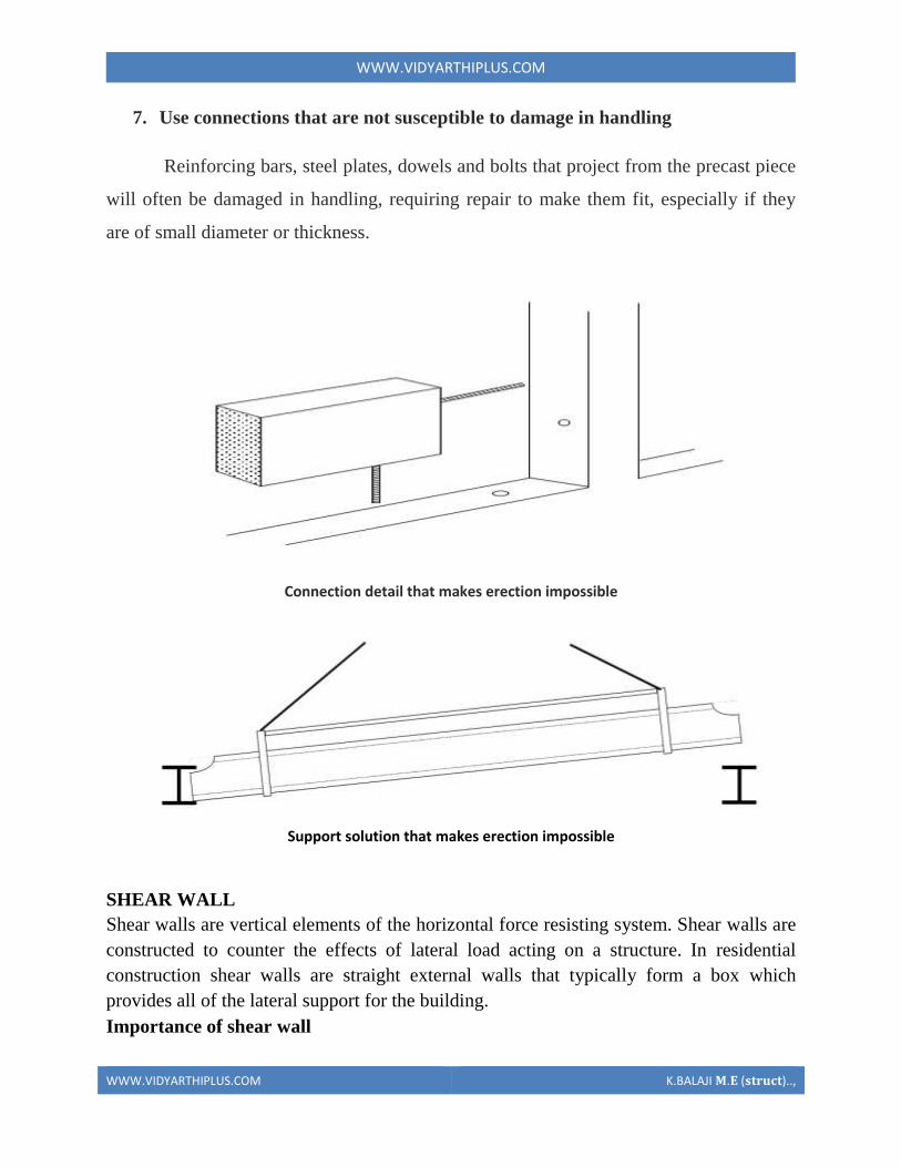
WWWVIDYARTHIPLUSCOM
WWWVIDYARTHIPLUSCOM KBALAJI 119820119812 (119852119853119851119854119836119853)
When shear walls are designed and constructed property and they will have the strength
and stiffness to resist the horizontal forces In building construction a rigid vertical
diaphragm capable of transferring lateral forces from exterior walls floors and roofs to
the ground foundation in a direction parallel to their planes Lateral forces caused by
wind earthquake and uneven settlement loads In addition to the weight of structure and
occupants create powerful twisting (torsion) forces These forces can literally tear (shear)
a building apart Reinforcing a frame by attaching or placing a rigid wall inside it
maintains that shape of the frame and prevents rotation at the joints shear walls are
especially important in high-rise building subjected to lateral wind and seismic forces
In the last two decades shear walls became an important part of mid high rise residential
buildings As part of an earthquake resistant building design these walls are placed in
building plans reducing lateral displacements under earthquake loads So shear wall
frame structure are obtained
Shear wall buildings are usually regular in plan and in elevation However in some
buildings lower floors are used for commercial purposes and the buildings are
characterized with larger plan dimensions at those floors
Purpose of constructing shear walls
1 Shear walls are not only designed to resist gravityvertical loads due to its self weight
amp other living moving loads) but they are also designed for lateral loads of
earthquakeswind The walls are structurally integrated with roofsfloors (diaphragms)
and other lateral
2Shear wall structural systems are more stable because their supporting area (Total
cross sectional area of all shear walls) with reference to total plans area of building is
comparatively more unlike in the case of RCC framed structures
3 Walls have to resist the uplift forces caused by the pull of the wind walls have to
resist the shear forces that try to push the walls over walls have to resist the lateral force
of the wind that tries to push the walls in and pull them away from the building
4 Walls floors and roofs to the ground foundation in a direction parallel to their planes
Lateral forces caused by wind earthquake and uneven settlement loads In addition to the
weight of structure and occupants create powerful twisting (torsion) forces These forces
can literally tear (shear) a building apart Reinforcing a frame by attaching or placing a
WWWVIDYARTHIPLUSCOM
WWWVIDYARTHIPLUSCOM KBALAJI 119820119812 (119852119853119851119854119836119853)
rigid wall inside it maintain the joints shear walls are especially important in high-rise
building subjected to lateral wind and seismic forces
In the last two decades shear walls became as important part of mid high rise residential
buildings As part of an earthquake resistant building design these walls are placed in
building plans reducing lateral displacements under earthquake loads So shear wall
frame structures are obtained
Shear wall buildings are usually regular in plan and in elevation However in some
buildings lower floors are used for commercial purposes and the buildings are
characterized with larger plan dimensions at these floors
Comparisons of shear wall with construction of conventional load bearing walls
Load bearing masonry is very brittle material Due to different kinds of stresses such as
shear tensileetc Caused by the earthquakes the conventional unreinforced brick
masonry collapses instantly during the unpredictable and sudden earthquakes
The RCC framed structures are slender When compared to shear wall concept of box
like three-dimensional structures though it is possible to design the earthquake resistant
RCC frame it requires extra-ordinary skills at design detailing and construction levels
Which cannot be anticipated in all types of construction projects
On the other hand even moderately designed shear wall structures not only more stable
but also comparatively quite ductile In safety terms it means that during very severe
earthquakes they will not suddenly collapse causing death of people They give enough
indicative warnings such as widening structural cracks yielding rods etc offering most
precious moment for people to run out off structures before they totally collapse
For structural purposes we consider the exterior walls as the shear resisting walls Forces
from the ceiling and roof diaphragms make their way to the outside along assumed paths
enter the walls and exit at the foundation
Forces on shear wall
Shear wall resist two types of forces
1 Shear forces
2 Uplift forces
Shear Forces
Shear forces are generated in stationary buildings by accelerations resulting from ground
movement and by external forces like wind amp waves This action creates shear forces
throughout the height of the wall between the top and bottom shear wall connections
Uplift Forces
WWWVIDYARTHIPLUSCOM
WWWVIDYARTHIPLUSCOM KBALAJI 119820119812 (119852119853119851119854119836119853)
Uplift forces exist on shear walls because the horizontal forces are applied to the top of
the wall These uplift forces try to lift up one end of the wall and push the other end
down In some cases the uplift force is large enough to tip the wall over Uplift forces are
greater on tall short walls uplift shear walls need hold down devices at each end when the
gravity loads cannot resist all of the uplift The hold down device then provides the
necessary uplift resistance
Classification of shear walls
1 Simple rectangular types amp flanged walls
2 Coupled shear walls
3 Rigid frame shear walls
4 Framed walls with in filled frames
5 Column supported shear walls
6 Core type shear walls
Types of shear walls
1 RC shear wall
2 Plywood shear wall
3 Mid ply shear wall
WWWVIDYARTHIPLUSCOM
WWWVIDYARTHIPLUSCOM KBALAJI 119820119812 (119852119853119851119854119836119853)
4 RC Hollow concrete Block masonry wall
5 Steel plate shear wall
RC shear wall
It consists of reinforced concrete walls and reinforced concrete slabs wall thickness varies
from 140 mm to 500 mm depending on the number of stories building age and thermal
insulation requirement In general these walls are continuous throughout the building
height however Some walls are discontinued as the steel front or basement level to allow
for commercial or parking spaces Floors slabs are either cast in-situ flat slabs or less
often Precast hollow core slabs Buildings are supported by concrete strip or mat
foundations the latter type is common for buildings with basements
Ply wood shear wall
Plywood is the traditional material used in the construction of shear walls the creation of
pre-fabricated shear panels have made it possible to inject strong shear assemblies into
small walls that fall at either side of a opening in a shear wall plywood shear wall consist
of
o Plywood to transfer shear forces
o Chords to resist tensioncompression generated by the over turning
moments
o Base connections to transfer shear to foundations
Midply shear wall
The midply shear wall is an improved timber shear wall that was developed by
redesigning the joints between shearing and finishing members So that the failure modes
observed in standard wall testing are virtually eliminated at lateral loads levels high
enough to cause failures in standard walls
RC Hollow concrete block masonry walls (RHCBM)
These walls are constructed by reinforcing the hollow concrete block masonry by taking
advantage of hollow spaces amp shapes of the hollow blocks It requires continuous steel
rods (reinforcement) both in the vertical amp horizontal directions at structurally critical
locations of the wall panels packed with the fresh grout concrete in the hollow spaces of
masonry bocks
RHCBC elements are designed both as load bearing walls for gravity loads and also as
shear walls for lateral seismic loads to safety withstand earthquakes
Steel plate shear wall
In general steel plate shear wall system consists of a steel plate wall boundary columns
and horizontal floor beams Together the steel plate wall and boundary columns act as a
vertical plate girder The column act as flanges of the vertical plate girder and the steel
WWWVIDYARTHIPLUSCOM
WWWVIDYARTHIPLUSCOM KBALAJI 119820119812 (119852119853119851119854119836119853)
plates wall act as its web The horizontal floor beams act more or less as transverse
stiffeners in a plate girder steel plate shear wall systems have been used in recent years in
highly seismic area to resist lateral loads
Thus shear walls are one of the most effective building elements in resisting lateral forces
during earthquake By constructing shear walls damages due to effect of lateral forces
due to earthquake and high winds can be minimized shear walls construction will provide
larger stiffness to the buildings there by reducing the damage to structure and its contents
Hence it is preferable to have all these prefabricate approximately of some weight very
near to the lifting capacity of the equipment
SHEAR WALL
WWWVIDYARTHIPLUSCOM
WWWVIDYARTHIPLUSCOM KBALAJI 119820119812 (119852119853119851119854119836119853)
WWWVIDYARTHIPLUSCOM
WWWVIDYARTHIPLUSCOM KBALAJI 119820119812 (119852119853119851119854119836119853)
WWWVIDYARTHIPLUSCOM
WWWVIDYARTHIPLUSCOM KBALAJI 119820119812 (119852119853119851119854119836119853)
Off-site fabrication
Off-Site fabrication is a process that incorporates prefabrication and pre-assembly The
process involves the design and manufacture of units or modules usually remote from the
work site and the installation at the site to form the permanent works at the site In its
fullest sense off-site fabrication requires a project strategy that will change the
orientation of the project process from construction to manufacture to installation
Examples of off-site fabrication are wall panels for homes wooden truss bridge spans
airport control stations
There are 4 main categories of Off-Site fabrication which is often also referred to as Off-
Site Construction These can be described as component (or sub-assembly) systems
penalized systems volumetric systems and modular systems Below these categories
different branches or technologies are being developed There are a vast number of
different systems on the market which fall into these categories and with recent advances
in digital design such as Building Information Modeling (BIM) the task of integrating
WWWVIDYARTHIPLUSCOM
WWWVIDYARTHIPLUSCOM KBALAJI 119820119812 (119852119853119851119854119836119853)
these different systems into a construction project is becoming increasingly a digital
management proposition
Unit -1
Question with answer
Part-A-
1Define prefabrication
The term prefab can apply to any construction method where the significant part of the
construction takes place off site in a factory That produces relatively large complex
features that assembled at the site into the finished building
2What is meant by modular Coordination
Modular coordination is a concept for coordinating dimension and space for which
building and component are dimensionally it used and positioned in basic units (or)
modules
The standard specify that the module basic M = 100 mm As the basic unit be used in a
square of M
3What are the characteristics of Modular concept
I) The basic module is small in terms of add size in order to provide design flexibility
yet large enough to promote simplification in the component variation in sizes
II) Industry friendly features that not only for manufacturing but also the transportation
and assembly requirements
III) Internationally accepted to support international market
4 Write out the advantages amp disadvantages of prefabrication
I) Self supporting readymade components are used so the need for formwork shuttering
and scaffolding is greatly reduced
II) On-site construction and condition is minimized
III) Less waste may occur
Disadvantages
I)Careful handling of prefabricated components such as concrete panels (or) steel and
glass Panels is reduced
II) Similarly leaks can form at joints is prefabricated component
5) Define the term Off-site fabrication
WWWVIDYARTHIPLUSCOM
WWWVIDYARTHIPLUSCOM KBALAJI 119820119812 (119852119853119851119854119836119853)
Off-site fabrication is the process that incorporates prefabrication and preassemble the
process involves the design and manufacture of units usually remote from the work site
and the installation at the site to form the permanent work at the site
6) Write short note on Production process
The production of concrete blocks consists of four basic process They are
1) Mixing
2) Moulding
3) Curing
4) Cubing
7) List out the limitations of prefabrication
I) Extra reinforcement is required to take care of handling and erection stresses
II) Temporary props may be required in some cases before the un-site concrete joints
achieve strength
III) The cracks may develop at the joints between the precart in ndashsite concrete due to
shrinkage and temperature stresses To overcome them extra steel is required across
joint
8) What are all the Prefab materials
Structural insulated panels (SIPs)
Insulating concrete forms (ICFS)
Prefab foundation system
Steel framing
Concrete framing
Large - modular system
9) Insulating concrete forms
Insulating concrete forms (ICE) are a prefab construction material consisting of hollow
EPS foam blocks that are stacked and glued together on-site creating the form that is
filled with reinforcing bars and concrete
10) Write short note on Principles of MC Concept
The principle objective of implanting MC is to improve productivity through the
reduction of wastages in the production installation process to improve quality in the
construction industry and to encourage an open system
WWWVIDYARTHIPLUSCOM
WWWVIDYARTHIPLUSCOM KBALAJI 119820119812 (119852119853119851119854119836119853)
11 Define shear wall
These are simple type and these shear walls under forces and horizontal shear along its
length are subjected to bending and shear To resist these forces the uniform
distribution of steel along its length is used in simple shear walls
12 Different classification of shear walls
1) Plain rectangular shear wall
2) Bar bell type
3) Framed shear wall
4) Coupled shear wall
5) Care type
13What is Modular Coordination
Modular coordination or MC is a dimensional system It is a dimension and space
coordination concept in which building and components are placed at their
designations based on the unit
14 How dimensional coordination is helpful in prefabricated structures
Building production is the organization and management of the plans equipment
materials and labour involved in the construction of a building while at the same time
complying with all codes rules and contractual stipulations The procedure should be
designed to run efficiently to keep the costs low and to allow returns on the
investment to be realized as early as possible
15 Explain the term basic module
Modular are terms that usually refer to upscale housing that can be any combination
of pre-engineered home parts that re delivered to the building site ready to be
assembled in a quick manner
16 What are the factors to consider in transporting of prefabricated structures
Transport device being movable from the input end to the output end of the production
line through a series of workstations said building unit being fabricated on an upper
surface of said flatbed said flatbed having an anti-friction surface on the upper surface
WWWVIDYARTHIPLUSCOM
WWWVIDYARTHIPLUSCOM KBALAJI 119820119812 (119852119853119851119854119836119853)
thereof for permitting sliding movement of said building unit relative to said transport
device
17 Explain the role of shear connectors in pre fabricated structures
Shear connectors may be spaced uniformly between the sections of maximum and zero
moment Shear connectors should have at least 1 in (254 mm) of concrete cover in all
directions and unless studs are located directly over the web stud diameters may not
exceed 25 times the beam-flange thickness With heavy concentrated loads the uniform
spacing of shear connectors may not be sufficient between a concentrated load and the
nearest point of zero moment
18 What are the special material properties in of prefabricated structures
Quicktoassemble
Cost-effective
Portablemovable
Strong
Water proof Moisture proof
Fire Resistant
19 What are the types of shear walls
Vertical Offset of Shear Walls
Stiffness shear wall
Steel shear wall
20 Write short notes on prefabrication
Prefabrication is the practice of assembling components of a structure in a factory or
other manufacturing site and transporting complete assemblies or sub-assemblies to
the construction site where the structure is to be located prefabrication in
architectural construction a technique whereby large units of a building are produced
WWWVIDYARTHIPLUSCOM
WWWVIDYARTHIPLUSCOM KBALAJI 119820119812 (119852119853119851119854119836119853)
in factories to be assembled ready-made on the building site The technique permits
the speedy erection of very large structures
21 Write any two advantages of prefabrication construction
Self-supporting ready-made components are used so the need for formwork
shuttering and scaffolding is greatly reduced
Construction time is reduced and buildings are completed sooner allowing an
earlier return of the capital invested
22 Define the term module
23 Write short notes on shear wall
A shear wall is a wall which is designed to resist shear the lateral force which causes
the bulk of damage in earthquakes
24 Write any two prefabrication problem of materials
Non availability of materials
Economy
25 Write the types of Derricks
A derrick is a lifting device composed of one mast or pole which is hinged freely at
the bottom It is controlled by lines powered by some means such as man-hauling or
motors so that the pole can move in all four directions
Hallen Derrick
Velle Derrick
Stuumllcken Derrick
26 What are the advantages of prefabricated structures
WWWVIDYARTHIPLUSCOM
WWWVIDYARTHIPLUSCOM KBALAJI 119820119812 (119852119853119851119854119836119853)
On-site construction and congestion is minimized
Quality control can be easier in a factory assembly line setting than a construction
site setting
Prefabrication can be located where skilled labour is more readily available and
costs of labour power materials space and overheads are lower
Time spent in bad weather or hazardous environments at the construction site is
minimised
27 What are the safety factors to be considered in designing
28 Explain about the location of shear wall
Lateral forces caused by wind earthquake and uneven settlement loads in addition to
the weight of structure and occupants create powerful twisting (torsional) forces
These forces can literally tear (shear) a building apart Reinforcing a frame by
attaching or placing a rigid wall inside it maintains the shape of the frame and
prevents rotation at the joints Shear walls are especially important in high-rise
buildings subject to lateral wind and seismic forces
29 What are the lateral loads in a building Live load
Wind load
Earthquake load 30What are the lateral load resisting elements in a building (AUC NovDec 2013) Vertical Elements
Moment
Resisting Frames
Walls
Bearing walls Shear Walls Structural Walls
Gravity Frame + Walls
ldquoDualrdquo System (Frame + Wall)
WWWVIDYARTHIPLUSCOM
WWWVIDYARTHIPLUSCOM KBALAJI 119820119812 (119852119853119851119854119836119853)
Vertical Truss
Tube System
Bundled
Tube System FloorDiaphragm
Foundation
WWWVIDYARTHIPLUSCOM
WWWVIDYARTHIPLUSCOM KBALAJI 119820119812 (119852119853119851119854119836119853)
Part-B
1Explain Modular Coordination in detail
Modular coordination means the interdependent arrangement of a dimension based on a
primary value accepted as a module The strict observance of rules of modular
coordination facilitated
1 Assembly of single components into large components
2 Fewest possible different types of component
3 Minimum wastage of cutting needed
Modular coordination is the basis for a standardization of a mass production of
component A
set of rules would be adequate for meeting the requirements of conventional and
prefabricated construction These rules are adaptable for
a The planning grid in both directions of the horizontal plan shall be
1 3M for residential and institutional buildings
2 For industrial buildings
WWWVIDYARTHIPLUSCOM
WWWVIDYARTHIPLUSCOM KBALAJI 119820119812 (119852119853119851119854119836119853)
15M for spans up to 12m
30M for spans between 12m and 18m
60M for spans over 18m
The centre lines of load bearing walls shall coincide with the grid lines
b In case of external walls the grid lines shall coincide with the centre line of the wall or
a line on the wall 5 cm from the internal face of the wall
C The planning module in the vertical direction shall be 1M up to and including a ht of
28M
d Preferred increments for the still heights doors windows and other fenestration shall
be
1M
e In case of internal columns the grid lines shall coincide with the centre lines of
columns In case of external columns the grid lines shall coincide with the centre lines of
the columns in the storey or a line in the column from the internal face of the column in
the topmost storey A basic module can be represented as module and for larger project
modules are represented a Mp
For eg For a project module in horizontal coordination the component can be of 30cm
and for vertical component size be of 10cm
The storey height is fixed between finished floor levels as 28m and if the thickness of
slab is lt15cm storey height is fixed as 27m The centre distance between the load
bearing walls can be chose from a set of modules The use of other dimensions is not
allowed
In the design of a building modular grid can be used consisting of parallel line spaced at
a value of module M or Mp and a grid line chosen as a base for setting out a part of a
building becomes a modular axis In the fig (a) a typical grid is chosen for load bearing
walls without duct The interior walls are placed so that their centre lines coincide with
the modular axis In the fig (b) a grid is shown for load bearing walls with hollow ducts
in between The centre line of the grid is found by deducting the size of duct
WWWVIDYARTHIPLUSCOM
WWWVIDYARTHIPLUSCOM KBALAJI 119820119812 (119852119853119851119854119836119853)
2Systems of prefabrication
System is referred to a particular method of construction of buildings using the
prefabricated components which are inter related in functions and are produced to a set of
instructions With certain constraints several plans are possible using the same set of
components the degree of flexibility varies from system to system However in all the
systems there is a certain order and discipline The system of prefabricated construction
depends on the extend of the use of prefab components their characteristics to be
considered in devising a system
i Intensified usage of spaces
ii Straight and simple walling scheme
iii Limited sizes and numbers of components
iv Limited opening in bearing walls
v Regulated locations of partitions
vi Standardized service and stair units
vii Limited sizes of doors and windows with regulated positions
viii Structural clarity and efficiency
ix Suitability for adoption in low rise and high rise blocks
x Ease of manufacturing storing and transporting
xi Speed and ease of erection
xii Simple jointing system
a) Based on Disuniting of member
b) Based on the construction
WWWVIDYARTHIPLUSCOM
WWWVIDYARTHIPLUSCOM KBALAJI 119820119812 (119852119853119851119854119836119853)
Based on Disuniting of member
1 System consisting of linear member disunited at joints
2 System for prefabricates of entire rigid frame
3 System consisting of ITU of straight members disunited at points of minimum
moment
4 Two hinged and three hinged arches
System consisting of linear member disunited at joints
Advantage
Disuniting at joints gives linear member This means that a great advantage and facilitates
from the view point manufacture and assembly
Disadvantage
1 Joints are at corners ie at points of maximum moment values so forming the joint is
difficult
2 Joints must be over dimensioned to cope with in-situ concreting And one alternate
solution to replace moment resistant joints by hinged connection
System for prefabricates of entire rigid frame
WWWVIDYARTHIPLUSCOM
WWWVIDYARTHIPLUSCOM KBALAJI 119820119812 (119852119853119851119854119836119853)
In this system to reduce the no of joints and to precast larger numbers I one piece leads
to the prefabrication of entire frame Production of the frames does not cause any
particular trouble but the hoisting is more difficult and requires careful preparation The
stress distribution of straight members during hoisting is in general statistically
determinate
Advantage
1 It is ideal for site prefabrication
2 Small number of joints so rapid prefabrication work is possible
3 Suitable for long walls consisting of great number of uniform frames
System consisting of ITU of straight members disunited at points of minimum
moment
WWWVIDYARTHIPLUSCOM
WWWVIDYARTHIPLUSCOM KBALAJI 119820119812 (119852119853119851119854119836119853)
WWWVIDYARTHIPLUSCOM
WWWVIDYARTHIPLUSCOM KBALAJI 119820119812 (119852119853119851119854119836119853)
Another method of disuniting of structures is by division into different membranes at
points where the moments are thin or smallest This method is called as lambda method
Using this method hinge joints are made
Advantage
1 Functions are made at points of minimum moments or at points of contra flexure
2 Disuniting the main girder in this manner makes the application of different skylights
possible
Disadvantage
1 Hosting and temperature bracing of L joined asymmetric frame members is
WWWVIDYARTHIPLUSCOM
WWWVIDYARTHIPLUSCOM KBALAJI 119820119812 (119852119853119851119854119836119853)
particularly complicated
2 Temperature resting of frame member on each other necessitates the use of
cantilevers having half depth and proper forming of this cause difficulty
Two hinged and three hinged arches
Arched structures are normally two hinged and three hinged arches Arched structures are
normally used for bridging span more than 20-25m Their production and placing is more
difficult than straight members Arch can be two hinged and three hinged but they can
also be fixed at footings and can be constructed with or without tie
These members are generally precast and assembled in statistically determinant three
hinged variance and middle hinge is only eliminated after placing is finished The
reinforcing bars protruding both sides are welded together and the joint between the
members is filled in with insitu concrete
Arch structure can be precast in either vertical or horizontal positions In the first case
shuttering made of timber or concrete is required having the same curvature s the arch
itself
The prefabrication of larger arches in the horizontal position is found to be more
economical
The construction of arch trusses can be properly carried out in the horizontal position
only
WWWVIDYARTHIPLUSCOM
WWWVIDYARTHIPLUSCOM KBALAJI 119820119812 (119852119853119851119854119836119853)
3Methods of prefabrication
Site prefabrication- for large prefabricates
Plant prefabrication- large scale production
Site prefabrication
1 The RC members are produced t the site in the open air chiefly in the open air or in
the temporary sheds
2 The difficulties in construction in general are felt in this mechanization can case
3 Mechanization cannot be of such high degree as site PF is done for smaller duration
of time
4 When the pre fabricates are of large size it is difficult to transport the pre fabricates to
the site
5 In comparison with plant prefabrication transportation of the members are not needed
As large members are not transported the design and weight of the prefabricates are not
limited
Plant prefabrication
1 The members produced are to be transported t the place of construction this accounts
for about 10-15 of the cost of production and assembling
2 Certain restriction is made in the dimension of prefabrication leading to restraints in
the design and development of prefabrication
3 Prefabrication is appropriate for mass production for manufacture of standardized
members
4 Needs costly materials for batching and production
5 This method is most suited in the case of small prefabricates which are to be
prefabricated in very large number
Plant prefabrication is done under permanent plant or factories It is done under the
covered roof so the effect of weather does not affect the work So the quality and strength
of the members can be improved considerably Plant prefabrication reduces the cost of
prefabrication if the number of prefabricate needed is more
Dimensions of prefabricate
There are 3 commonly known dimension for the prefabricates
1 The design of the erection dimension governing the dimensional coordination of the
prefabricates
2 Theoretical dimension
3 The actual dimension of the element when delivered the design dimension should be a
multiple of a basic module size m or of a module lap
WWWVIDYARTHIPLUSCOM
WWWVIDYARTHIPLUSCOM KBALAJI 119820119812 (119852119853119851119854119836119853)
Production of prefabricates
Production techniques involved are
1 Stand method
2 Conveyor method or line method
3 Aggregate method
Stand Method
In this method the prefabrication mature where they are moulded while the production
teams moves to successive stands The bed on which prefabricates are cast may be fixed
or
movable Tilting forms are often used and in this method steam curing is generally done
Conveyor belt method
The whole production is split up in to series operations carried out at separate successive
and permanent points served by specialized teams The movement of the mould or
prefabricate one point to other vary by means of conveyor belt trolleys
The rigid steel forms are assembled at station 1 where they are mould oil to reduce the
adhesion of concrete The conveyor moves front 1 to 2 where prestressing wires are fixed
amp in the next station anchoring of the wires is carried out The prepared mould is then
carried to the station 1ie casting station After casting it is shifted to the vibrating table amp
finally stacked station 5 for setting After that it is passed through tunnel autoclave for
curing After steam curing move too station 7 for demoulding amp is finally stacked 8
Aggregate method
In the aggregate method aggregate describes large complex permanently installed
machines amp mechanical appliances which carry out most of the separate operations
involved in the casting of the concrete composition The stand is operated by a permanent
team amp the only move the prefabricate makes is to the maturing point
Aggregate method is used in the production of multi duct hollow floor panel in Poland
At production point the reinforcement is fixed in the form amp remote controlled
aggregate(machine)inserts the duct formers castamp vibrates the concrete floats the top
of the floor The prepared prefabricate then move to the autoclave chamber in which
hardening of concrete is accelerate In many factories combined technology are employed
when complex prefabricate are required
Advantages
1The stand technique is the most flexible one It is used in varying degrees of
mechanization in all kinds of prefabricate factories
2It is simple amp less capital is required It can be used for field prefabricate also
WWWVIDYARTHIPLUSCOM
WWWVIDYARTHIPLUSCOM KBALAJI 119820119812 (119852119853119851119854119836119853)
3Aggregate method is used for large scale production in which case number of
machineries is required
4 Explain specific requirements in layout of of prefabricated plants
WWWVIDYARTHIPLUSCOM
WWWVIDYARTHIPLUSCOM KBALAJI 119820119812 (119852119853119851119854119836119853)
WWWVIDYARTHIPLUSCOM
WWWVIDYARTHIPLUSCOM KBALAJI 119820119812 (119852119853119851119854119836119853)
5 Explain with neat sketch of the types of shear wall
WWWVIDYARTHIPLUSCOM
WWWVIDYARTHIPLUSCOM KBALAJI 119820119812 (119852119853119851119854119836119853)
WWWVIDYARTHIPLUSCOM
WWWVIDYARTHIPLUSCOM KBALAJI 119820119812 (119852119853119851119854119836119853)
6 What is the code use for prefabricated structures
WWWVIDYARTHIPLUSCOM
WWWVIDYARTHIPLUSCOM KBALAJI 119820119812 (119852119853119851119854119836119853)
7 Explain in detail various design consideration in the design of precast construction
WWWVIDYARTHIPLUSCOM
WWWVIDYARTHIPLUSCOM KBALAJI 119820119812 (119852119853119851119854119836119853)
WWWVIDYARTHIPLUSCOM
WWWVIDYARTHIPLUSCOM KBALAJI 119820119812 (119852119853119851119854119836119853)
rigid wall inside it maintain the joints shear walls are especially important in high-rise
building subjected to lateral wind and seismic forces
In the last two decades shear walls became as important part of mid high rise residential
buildings As part of an earthquake resistant building design these walls are placed in
building plans reducing lateral displacements under earthquake loads So shear wall
frame structures are obtained
Shear wall buildings are usually regular in plan and in elevation However in some
buildings lower floors are used for commercial purposes and the buildings are
characterized with larger plan dimensions at these floors
Comparisons of shear wall with construction of conventional load bearing walls
Load bearing masonry is very brittle material Due to different kinds of stresses such as
shear tensileetc Caused by the earthquakes the conventional unreinforced brick
masonry collapses instantly during the unpredictable and sudden earthquakes
The RCC framed structures are slender When compared to shear wall concept of box
like three-dimensional structures though it is possible to design the earthquake resistant
RCC frame it requires extra-ordinary skills at design detailing and construction levels
Which cannot be anticipated in all types of construction projects
On the other hand even moderately designed shear wall structures not only more stable
but also comparatively quite ductile In safety terms it means that during very severe
earthquakes they will not suddenly collapse causing death of people They give enough
indicative warnings such as widening structural cracks yielding rods etc offering most
precious moment for people to run out off structures before they totally collapse
For structural purposes we consider the exterior walls as the shear resisting walls Forces
from the ceiling and roof diaphragms make their way to the outside along assumed paths
enter the walls and exit at the foundation
Forces on shear wall
Shear wall resist two types of forces
1 Shear forces
2 Uplift forces
Shear Forces
Shear forces are generated in stationary buildings by accelerations resulting from ground
movement and by external forces like wind amp waves This action creates shear forces
throughout the height of the wall between the top and bottom shear wall connections
Uplift Forces
WWWVIDYARTHIPLUSCOM
WWWVIDYARTHIPLUSCOM KBALAJI 119820119812 (119852119853119851119854119836119853)
Uplift forces exist on shear walls because the horizontal forces are applied to the top of
the wall These uplift forces try to lift up one end of the wall and push the other end
down In some cases the uplift force is large enough to tip the wall over Uplift forces are
greater on tall short walls uplift shear walls need hold down devices at each end when the
gravity loads cannot resist all of the uplift The hold down device then provides the
necessary uplift resistance
Classification of shear walls
1 Simple rectangular types amp flanged walls
2 Coupled shear walls
3 Rigid frame shear walls
4 Framed walls with in filled frames
5 Column supported shear walls
6 Core type shear walls
Types of shear walls
1 RC shear wall
2 Plywood shear wall
3 Mid ply shear wall
WWWVIDYARTHIPLUSCOM
WWWVIDYARTHIPLUSCOM KBALAJI 119820119812 (119852119853119851119854119836119853)
4 RC Hollow concrete Block masonry wall
5 Steel plate shear wall
RC shear wall
It consists of reinforced concrete walls and reinforced concrete slabs wall thickness varies
from 140 mm to 500 mm depending on the number of stories building age and thermal
insulation requirement In general these walls are continuous throughout the building
height however Some walls are discontinued as the steel front or basement level to allow
for commercial or parking spaces Floors slabs are either cast in-situ flat slabs or less
often Precast hollow core slabs Buildings are supported by concrete strip or mat
foundations the latter type is common for buildings with basements
Ply wood shear wall
Plywood is the traditional material used in the construction of shear walls the creation of
pre-fabricated shear panels have made it possible to inject strong shear assemblies into
small walls that fall at either side of a opening in a shear wall plywood shear wall consist
of
o Plywood to transfer shear forces
o Chords to resist tensioncompression generated by the over turning
moments
o Base connections to transfer shear to foundations
Midply shear wall
The midply shear wall is an improved timber shear wall that was developed by
redesigning the joints between shearing and finishing members So that the failure modes
observed in standard wall testing are virtually eliminated at lateral loads levels high
enough to cause failures in standard walls
RC Hollow concrete block masonry walls (RHCBM)
These walls are constructed by reinforcing the hollow concrete block masonry by taking
advantage of hollow spaces amp shapes of the hollow blocks It requires continuous steel
rods (reinforcement) both in the vertical amp horizontal directions at structurally critical
locations of the wall panels packed with the fresh grout concrete in the hollow spaces of
masonry bocks
RHCBC elements are designed both as load bearing walls for gravity loads and also as
shear walls for lateral seismic loads to safety withstand earthquakes
Steel plate shear wall
In general steel plate shear wall system consists of a steel plate wall boundary columns
and horizontal floor beams Together the steel plate wall and boundary columns act as a
vertical plate girder The column act as flanges of the vertical plate girder and the steel
WWWVIDYARTHIPLUSCOM
WWWVIDYARTHIPLUSCOM KBALAJI 119820119812 (119852119853119851119854119836119853)
plates wall act as its web The horizontal floor beams act more or less as transverse
stiffeners in a plate girder steel plate shear wall systems have been used in recent years in
highly seismic area to resist lateral loads
Thus shear walls are one of the most effective building elements in resisting lateral forces
during earthquake By constructing shear walls damages due to effect of lateral forces
due to earthquake and high winds can be minimized shear walls construction will provide
larger stiffness to the buildings there by reducing the damage to structure and its contents
Hence it is preferable to have all these prefabricate approximately of some weight very
near to the lifting capacity of the equipment
SHEAR WALL
WWWVIDYARTHIPLUSCOM
WWWVIDYARTHIPLUSCOM KBALAJI 119820119812 (119852119853119851119854119836119853)
WWWVIDYARTHIPLUSCOM
WWWVIDYARTHIPLUSCOM KBALAJI 119820119812 (119852119853119851119854119836119853)
WWWVIDYARTHIPLUSCOM
WWWVIDYARTHIPLUSCOM KBALAJI 119820119812 (119852119853119851119854119836119853)
Off-site fabrication
Off-Site fabrication is a process that incorporates prefabrication and pre-assembly The
process involves the design and manufacture of units or modules usually remote from the
work site and the installation at the site to form the permanent works at the site In its
fullest sense off-site fabrication requires a project strategy that will change the
orientation of the project process from construction to manufacture to installation
Examples of off-site fabrication are wall panels for homes wooden truss bridge spans
airport control stations
There are 4 main categories of Off-Site fabrication which is often also referred to as Off-
Site Construction These can be described as component (or sub-assembly) systems
penalized systems volumetric systems and modular systems Below these categories
different branches or technologies are being developed There are a vast number of
different systems on the market which fall into these categories and with recent advances
in digital design such as Building Information Modeling (BIM) the task of integrating
WWWVIDYARTHIPLUSCOM
WWWVIDYARTHIPLUSCOM KBALAJI 119820119812 (119852119853119851119854119836119853)
these different systems into a construction project is becoming increasingly a digital
management proposition
Unit -1
Question with answer
Part-A-
1Define prefabrication
The term prefab can apply to any construction method where the significant part of the
construction takes place off site in a factory That produces relatively large complex
features that assembled at the site into the finished building
2What is meant by modular Coordination
Modular coordination is a concept for coordinating dimension and space for which
building and component are dimensionally it used and positioned in basic units (or)
modules
The standard specify that the module basic M = 100 mm As the basic unit be used in a
square of M
3What are the characteristics of Modular concept
I) The basic module is small in terms of add size in order to provide design flexibility
yet large enough to promote simplification in the component variation in sizes
II) Industry friendly features that not only for manufacturing but also the transportation
and assembly requirements
III) Internationally accepted to support international market
4 Write out the advantages amp disadvantages of prefabrication
I) Self supporting readymade components are used so the need for formwork shuttering
and scaffolding is greatly reduced
II) On-site construction and condition is minimized
III) Less waste may occur
Disadvantages
I)Careful handling of prefabricated components such as concrete panels (or) steel and
glass Panels is reduced
II) Similarly leaks can form at joints is prefabricated component
5) Define the term Off-site fabrication
WWWVIDYARTHIPLUSCOM
WWWVIDYARTHIPLUSCOM KBALAJI 119820119812 (119852119853119851119854119836119853)
Off-site fabrication is the process that incorporates prefabrication and preassemble the
process involves the design and manufacture of units usually remote from the work site
and the installation at the site to form the permanent work at the site
6) Write short note on Production process
The production of concrete blocks consists of four basic process They are
1) Mixing
2) Moulding
3) Curing
4) Cubing
7) List out the limitations of prefabrication
I) Extra reinforcement is required to take care of handling and erection stresses
II) Temporary props may be required in some cases before the un-site concrete joints
achieve strength
III) The cracks may develop at the joints between the precart in ndashsite concrete due to
shrinkage and temperature stresses To overcome them extra steel is required across
joint
8) What are all the Prefab materials
Structural insulated panels (SIPs)
Insulating concrete forms (ICFS)
Prefab foundation system
Steel framing
Concrete framing
Large - modular system
9) Insulating concrete forms
Insulating concrete forms (ICE) are a prefab construction material consisting of hollow
EPS foam blocks that are stacked and glued together on-site creating the form that is
filled with reinforcing bars and concrete
10) Write short note on Principles of MC Concept
The principle objective of implanting MC is to improve productivity through the
reduction of wastages in the production installation process to improve quality in the
construction industry and to encourage an open system
WWWVIDYARTHIPLUSCOM
WWWVIDYARTHIPLUSCOM KBALAJI 119820119812 (119852119853119851119854119836119853)
11 Define shear wall
These are simple type and these shear walls under forces and horizontal shear along its
length are subjected to bending and shear To resist these forces the uniform
distribution of steel along its length is used in simple shear walls
12 Different classification of shear walls
1) Plain rectangular shear wall
2) Bar bell type
3) Framed shear wall
4) Coupled shear wall
5) Care type
13What is Modular Coordination
Modular coordination or MC is a dimensional system It is a dimension and space
coordination concept in which building and components are placed at their
designations based on the unit
14 How dimensional coordination is helpful in prefabricated structures
Building production is the organization and management of the plans equipment
materials and labour involved in the construction of a building while at the same time
complying with all codes rules and contractual stipulations The procedure should be
designed to run efficiently to keep the costs low and to allow returns on the
investment to be realized as early as possible
15 Explain the term basic module
Modular are terms that usually refer to upscale housing that can be any combination
of pre-engineered home parts that re delivered to the building site ready to be
assembled in a quick manner
16 What are the factors to consider in transporting of prefabricated structures
Transport device being movable from the input end to the output end of the production
line through a series of workstations said building unit being fabricated on an upper
surface of said flatbed said flatbed having an anti-friction surface on the upper surface
WWWVIDYARTHIPLUSCOM
WWWVIDYARTHIPLUSCOM KBALAJI 119820119812 (119852119853119851119854119836119853)
thereof for permitting sliding movement of said building unit relative to said transport
device
17 Explain the role of shear connectors in pre fabricated structures
Shear connectors may be spaced uniformly between the sections of maximum and zero
moment Shear connectors should have at least 1 in (254 mm) of concrete cover in all
directions and unless studs are located directly over the web stud diameters may not
exceed 25 times the beam-flange thickness With heavy concentrated loads the uniform
spacing of shear connectors may not be sufficient between a concentrated load and the
nearest point of zero moment
18 What are the special material properties in of prefabricated structures
Quicktoassemble
Cost-effective
Portablemovable
Strong
Water proof Moisture proof
Fire Resistant
19 What are the types of shear walls
Vertical Offset of Shear Walls
Stiffness shear wall
Steel shear wall
20 Write short notes on prefabrication
Prefabrication is the practice of assembling components of a structure in a factory or
other manufacturing site and transporting complete assemblies or sub-assemblies to
the construction site where the structure is to be located prefabrication in
architectural construction a technique whereby large units of a building are produced
WWWVIDYARTHIPLUSCOM
WWWVIDYARTHIPLUSCOM KBALAJI 119820119812 (119852119853119851119854119836119853)
in factories to be assembled ready-made on the building site The technique permits
the speedy erection of very large structures
21 Write any two advantages of prefabrication construction
Self-supporting ready-made components are used so the need for formwork
shuttering and scaffolding is greatly reduced
Construction time is reduced and buildings are completed sooner allowing an
earlier return of the capital invested
22 Define the term module
23 Write short notes on shear wall
A shear wall is a wall which is designed to resist shear the lateral force which causes
the bulk of damage in earthquakes
24 Write any two prefabrication problem of materials
Non availability of materials
Economy
25 Write the types of Derricks
A derrick is a lifting device composed of one mast or pole which is hinged freely at
the bottom It is controlled by lines powered by some means such as man-hauling or
motors so that the pole can move in all four directions
Hallen Derrick
Velle Derrick
Stuumllcken Derrick
26 What are the advantages of prefabricated structures
WWWVIDYARTHIPLUSCOM
WWWVIDYARTHIPLUSCOM KBALAJI 119820119812 (119852119853119851119854119836119853)
On-site construction and congestion is minimized
Quality control can be easier in a factory assembly line setting than a construction
site setting
Prefabrication can be located where skilled labour is more readily available and
costs of labour power materials space and overheads are lower
Time spent in bad weather or hazardous environments at the construction site is
minimised
27 What are the safety factors to be considered in designing
28 Explain about the location of shear wall
Lateral forces caused by wind earthquake and uneven settlement loads in addition to
the weight of structure and occupants create powerful twisting (torsional) forces
These forces can literally tear (shear) a building apart Reinforcing a frame by
attaching or placing a rigid wall inside it maintains the shape of the frame and
prevents rotation at the joints Shear walls are especially important in high-rise
buildings subject to lateral wind and seismic forces
29 What are the lateral loads in a building Live load
Wind load
Earthquake load 30What are the lateral load resisting elements in a building (AUC NovDec 2013) Vertical Elements
Moment
Resisting Frames
Walls
Bearing walls Shear Walls Structural Walls
Gravity Frame + Walls
ldquoDualrdquo System (Frame + Wall)
WWWVIDYARTHIPLUSCOM
WWWVIDYARTHIPLUSCOM KBALAJI 119820119812 (119852119853119851119854119836119853)
Vertical Truss
Tube System
Bundled
Tube System FloorDiaphragm
Foundation
WWWVIDYARTHIPLUSCOM
WWWVIDYARTHIPLUSCOM KBALAJI 119820119812 (119852119853119851119854119836119853)
Part-B
1Explain Modular Coordination in detail
Modular coordination means the interdependent arrangement of a dimension based on a
primary value accepted as a module The strict observance of rules of modular
coordination facilitated
1 Assembly of single components into large components
2 Fewest possible different types of component
3 Minimum wastage of cutting needed
Modular coordination is the basis for a standardization of a mass production of
component A
set of rules would be adequate for meeting the requirements of conventional and
prefabricated construction These rules are adaptable for
a The planning grid in both directions of the horizontal plan shall be
1 3M for residential and institutional buildings
2 For industrial buildings
WWWVIDYARTHIPLUSCOM
WWWVIDYARTHIPLUSCOM KBALAJI 119820119812 (119852119853119851119854119836119853)
15M for spans up to 12m
30M for spans between 12m and 18m
60M for spans over 18m
The centre lines of load bearing walls shall coincide with the grid lines
b In case of external walls the grid lines shall coincide with the centre line of the wall or
a line on the wall 5 cm from the internal face of the wall
C The planning module in the vertical direction shall be 1M up to and including a ht of
28M
d Preferred increments for the still heights doors windows and other fenestration shall
be
1M
e In case of internal columns the grid lines shall coincide with the centre lines of
columns In case of external columns the grid lines shall coincide with the centre lines of
the columns in the storey or a line in the column from the internal face of the column in
the topmost storey A basic module can be represented as module and for larger project
modules are represented a Mp
For eg For a project module in horizontal coordination the component can be of 30cm
and for vertical component size be of 10cm
The storey height is fixed between finished floor levels as 28m and if the thickness of
slab is lt15cm storey height is fixed as 27m The centre distance between the load
bearing walls can be chose from a set of modules The use of other dimensions is not
allowed
In the design of a building modular grid can be used consisting of parallel line spaced at
a value of module M or Mp and a grid line chosen as a base for setting out a part of a
building becomes a modular axis In the fig (a) a typical grid is chosen for load bearing
walls without duct The interior walls are placed so that their centre lines coincide with
the modular axis In the fig (b) a grid is shown for load bearing walls with hollow ducts
in between The centre line of the grid is found by deducting the size of duct
WWWVIDYARTHIPLUSCOM
WWWVIDYARTHIPLUSCOM KBALAJI 119820119812 (119852119853119851119854119836119853)
2Systems of prefabrication
System is referred to a particular method of construction of buildings using the
prefabricated components which are inter related in functions and are produced to a set of
instructions With certain constraints several plans are possible using the same set of
components the degree of flexibility varies from system to system However in all the
systems there is a certain order and discipline The system of prefabricated construction
depends on the extend of the use of prefab components their characteristics to be
considered in devising a system
i Intensified usage of spaces
ii Straight and simple walling scheme
iii Limited sizes and numbers of components
iv Limited opening in bearing walls
v Regulated locations of partitions
vi Standardized service and stair units
vii Limited sizes of doors and windows with regulated positions
viii Structural clarity and efficiency
ix Suitability for adoption in low rise and high rise blocks
x Ease of manufacturing storing and transporting
xi Speed and ease of erection
xii Simple jointing system
a) Based on Disuniting of member
b) Based on the construction
WWWVIDYARTHIPLUSCOM
WWWVIDYARTHIPLUSCOM KBALAJI 119820119812 (119852119853119851119854119836119853)
Based on Disuniting of member
1 System consisting of linear member disunited at joints
2 System for prefabricates of entire rigid frame
3 System consisting of ITU of straight members disunited at points of minimum
moment
4 Two hinged and three hinged arches
System consisting of linear member disunited at joints
Advantage
Disuniting at joints gives linear member This means that a great advantage and facilitates
from the view point manufacture and assembly
Disadvantage
1 Joints are at corners ie at points of maximum moment values so forming the joint is
difficult
2 Joints must be over dimensioned to cope with in-situ concreting And one alternate
solution to replace moment resistant joints by hinged connection
System for prefabricates of entire rigid frame
WWWVIDYARTHIPLUSCOM
WWWVIDYARTHIPLUSCOM KBALAJI 119820119812 (119852119853119851119854119836119853)
In this system to reduce the no of joints and to precast larger numbers I one piece leads
to the prefabrication of entire frame Production of the frames does not cause any
particular trouble but the hoisting is more difficult and requires careful preparation The
stress distribution of straight members during hoisting is in general statistically
determinate
Advantage
1 It is ideal for site prefabrication
2 Small number of joints so rapid prefabrication work is possible
3 Suitable for long walls consisting of great number of uniform frames
System consisting of ITU of straight members disunited at points of minimum
moment
WWWVIDYARTHIPLUSCOM
WWWVIDYARTHIPLUSCOM KBALAJI 119820119812 (119852119853119851119854119836119853)
WWWVIDYARTHIPLUSCOM
WWWVIDYARTHIPLUSCOM KBALAJI 119820119812 (119852119853119851119854119836119853)
Another method of disuniting of structures is by division into different membranes at
points where the moments are thin or smallest This method is called as lambda method
Using this method hinge joints are made
Advantage
1 Functions are made at points of minimum moments or at points of contra flexure
2 Disuniting the main girder in this manner makes the application of different skylights
possible
Disadvantage
1 Hosting and temperature bracing of L joined asymmetric frame members is
WWWVIDYARTHIPLUSCOM
WWWVIDYARTHIPLUSCOM KBALAJI 119820119812 (119852119853119851119854119836119853)
particularly complicated
2 Temperature resting of frame member on each other necessitates the use of
cantilevers having half depth and proper forming of this cause difficulty
Two hinged and three hinged arches
Arched structures are normally two hinged and three hinged arches Arched structures are
normally used for bridging span more than 20-25m Their production and placing is more
difficult than straight members Arch can be two hinged and three hinged but they can
also be fixed at footings and can be constructed with or without tie
These members are generally precast and assembled in statistically determinant three
hinged variance and middle hinge is only eliminated after placing is finished The
reinforcing bars protruding both sides are welded together and the joint between the
members is filled in with insitu concrete
Arch structure can be precast in either vertical or horizontal positions In the first case
shuttering made of timber or concrete is required having the same curvature s the arch
itself
The prefabrication of larger arches in the horizontal position is found to be more
economical
The construction of arch trusses can be properly carried out in the horizontal position
only
WWWVIDYARTHIPLUSCOM
WWWVIDYARTHIPLUSCOM KBALAJI 119820119812 (119852119853119851119854119836119853)
3Methods of prefabrication
Site prefabrication- for large prefabricates
Plant prefabrication- large scale production
Site prefabrication
1 The RC members are produced t the site in the open air chiefly in the open air or in
the temporary sheds
2 The difficulties in construction in general are felt in this mechanization can case
3 Mechanization cannot be of such high degree as site PF is done for smaller duration
of time
4 When the pre fabricates are of large size it is difficult to transport the pre fabricates to
the site
5 In comparison with plant prefabrication transportation of the members are not needed
As large members are not transported the design and weight of the prefabricates are not
limited
Plant prefabrication
1 The members produced are to be transported t the place of construction this accounts
for about 10-15 of the cost of production and assembling
2 Certain restriction is made in the dimension of prefabrication leading to restraints in
the design and development of prefabrication
3 Prefabrication is appropriate for mass production for manufacture of standardized
members
4 Needs costly materials for batching and production
5 This method is most suited in the case of small prefabricates which are to be
prefabricated in very large number
Plant prefabrication is done under permanent plant or factories It is done under the
covered roof so the effect of weather does not affect the work So the quality and strength
of the members can be improved considerably Plant prefabrication reduces the cost of
prefabrication if the number of prefabricate needed is more
Dimensions of prefabricate
There are 3 commonly known dimension for the prefabricates
1 The design of the erection dimension governing the dimensional coordination of the
prefabricates
2 Theoretical dimension
3 The actual dimension of the element when delivered the design dimension should be a
multiple of a basic module size m or of a module lap
WWWVIDYARTHIPLUSCOM
WWWVIDYARTHIPLUSCOM KBALAJI 119820119812 (119852119853119851119854119836119853)
Production of prefabricates
Production techniques involved are
1 Stand method
2 Conveyor method or line method
3 Aggregate method
Stand Method
In this method the prefabrication mature where they are moulded while the production
teams moves to successive stands The bed on which prefabricates are cast may be fixed
or
movable Tilting forms are often used and in this method steam curing is generally done
Conveyor belt method
The whole production is split up in to series operations carried out at separate successive
and permanent points served by specialized teams The movement of the mould or
prefabricate one point to other vary by means of conveyor belt trolleys
The rigid steel forms are assembled at station 1 where they are mould oil to reduce the
adhesion of concrete The conveyor moves front 1 to 2 where prestressing wires are fixed
amp in the next station anchoring of the wires is carried out The prepared mould is then
carried to the station 1ie casting station After casting it is shifted to the vibrating table amp
finally stacked station 5 for setting After that it is passed through tunnel autoclave for
curing After steam curing move too station 7 for demoulding amp is finally stacked 8
Aggregate method
In the aggregate method aggregate describes large complex permanently installed
machines amp mechanical appliances which carry out most of the separate operations
involved in the casting of the concrete composition The stand is operated by a permanent
team amp the only move the prefabricate makes is to the maturing point
Aggregate method is used in the production of multi duct hollow floor panel in Poland
At production point the reinforcement is fixed in the form amp remote controlled
aggregate(machine)inserts the duct formers castamp vibrates the concrete floats the top
of the floor The prepared prefabricate then move to the autoclave chamber in which
hardening of concrete is accelerate In many factories combined technology are employed
when complex prefabricate are required
Advantages
1The stand technique is the most flexible one It is used in varying degrees of
mechanization in all kinds of prefabricate factories
2It is simple amp less capital is required It can be used for field prefabricate also
WWWVIDYARTHIPLUSCOM
WWWVIDYARTHIPLUSCOM KBALAJI 119820119812 (119852119853119851119854119836119853)
3Aggregate method is used for large scale production in which case number of
machineries is required
4 Explain specific requirements in layout of of prefabricated plants
WWWVIDYARTHIPLUSCOM
WWWVIDYARTHIPLUSCOM KBALAJI 119820119812 (119852119853119851119854119836119853)
WWWVIDYARTHIPLUSCOM
WWWVIDYARTHIPLUSCOM KBALAJI 119820119812 (119852119853119851119854119836119853)
5 Explain with neat sketch of the types of shear wall
WWWVIDYARTHIPLUSCOM
WWWVIDYARTHIPLUSCOM KBALAJI 119820119812 (119852119853119851119854119836119853)
WWWVIDYARTHIPLUSCOM
WWWVIDYARTHIPLUSCOM KBALAJI 119820119812 (119852119853119851119854119836119853)
6 What is the code use for prefabricated structures
WWWVIDYARTHIPLUSCOM
WWWVIDYARTHIPLUSCOM KBALAJI 119820119812 (119852119853119851119854119836119853)
7 Explain in detail various design consideration in the design of precast construction
WWWVIDYARTHIPLUSCOM
WWWVIDYARTHIPLUSCOM KBALAJI 119820119812 (119852119853119851119854119836119853)

WWWVIDYARTHIPLUSCOM
WWWVIDYARTHIPLUSCOM KBALAJI 119820119812 (119852119853119851119854119836119853)
Uplift forces exist on shear walls because the horizontal forces are applied to the top of
the wall These uplift forces try to lift up one end of the wall and push the other end
down In some cases the uplift force is large enough to tip the wall over Uplift forces are
greater on tall short walls uplift shear walls need hold down devices at each end when the
gravity loads cannot resist all of the uplift The hold down device then provides the
necessary uplift resistance
Classification of shear walls
1 Simple rectangular types amp flanged walls
2 Coupled shear walls
3 Rigid frame shear walls
4 Framed walls with in filled frames
5 Column supported shear walls
6 Core type shear walls
Types of shear walls
1 RC shear wall
2 Plywood shear wall
3 Mid ply shear wall
WWWVIDYARTHIPLUSCOM
WWWVIDYARTHIPLUSCOM KBALAJI 119820119812 (119852119853119851119854119836119853)
4 RC Hollow concrete Block masonry wall
5 Steel plate shear wall
RC shear wall
It consists of reinforced concrete walls and reinforced concrete slabs wall thickness varies
from 140 mm to 500 mm depending on the number of stories building age and thermal
insulation requirement In general these walls are continuous throughout the building
height however Some walls are discontinued as the steel front or basement level to allow
for commercial or parking spaces Floors slabs are either cast in-situ flat slabs or less
often Precast hollow core slabs Buildings are supported by concrete strip or mat
foundations the latter type is common for buildings with basements
Ply wood shear wall
Plywood is the traditional material used in the construction of shear walls the creation of
pre-fabricated shear panels have made it possible to inject strong shear assemblies into
small walls that fall at either side of a opening in a shear wall plywood shear wall consist
of
o Plywood to transfer shear forces
o Chords to resist tensioncompression generated by the over turning
moments
o Base connections to transfer shear to foundations
Midply shear wall
The midply shear wall is an improved timber shear wall that was developed by
redesigning the joints between shearing and finishing members So that the failure modes
observed in standard wall testing are virtually eliminated at lateral loads levels high
enough to cause failures in standard walls
RC Hollow concrete block masonry walls (RHCBM)
These walls are constructed by reinforcing the hollow concrete block masonry by taking
advantage of hollow spaces amp shapes of the hollow blocks It requires continuous steel
rods (reinforcement) both in the vertical amp horizontal directions at structurally critical
locations of the wall panels packed with the fresh grout concrete in the hollow spaces of
masonry bocks
RHCBC elements are designed both as load bearing walls for gravity loads and also as
shear walls for lateral seismic loads to safety withstand earthquakes
Steel plate shear wall
In general steel plate shear wall system consists of a steel plate wall boundary columns
and horizontal floor beams Together the steel plate wall and boundary columns act as a
vertical plate girder The column act as flanges of the vertical plate girder and the steel
WWWVIDYARTHIPLUSCOM
WWWVIDYARTHIPLUSCOM KBALAJI 119820119812 (119852119853119851119854119836119853)
plates wall act as its web The horizontal floor beams act more or less as transverse
stiffeners in a plate girder steel plate shear wall systems have been used in recent years in
highly seismic area to resist lateral loads
Thus shear walls are one of the most effective building elements in resisting lateral forces
during earthquake By constructing shear walls damages due to effect of lateral forces
due to earthquake and high winds can be minimized shear walls construction will provide
larger stiffness to the buildings there by reducing the damage to structure and its contents
Hence it is preferable to have all these prefabricate approximately of some weight very
near to the lifting capacity of the equipment
SHEAR WALL
WWWVIDYARTHIPLUSCOM
WWWVIDYARTHIPLUSCOM KBALAJI 119820119812 (119852119853119851119854119836119853)
WWWVIDYARTHIPLUSCOM
WWWVIDYARTHIPLUSCOM KBALAJI 119820119812 (119852119853119851119854119836119853)
WWWVIDYARTHIPLUSCOM
WWWVIDYARTHIPLUSCOM KBALAJI 119820119812 (119852119853119851119854119836119853)
Off-site fabrication
Off-Site fabrication is a process that incorporates prefabrication and pre-assembly The
process involves the design and manufacture of units or modules usually remote from the
work site and the installation at the site to form the permanent works at the site In its
fullest sense off-site fabrication requires a project strategy that will change the
orientation of the project process from construction to manufacture to installation
Examples of off-site fabrication are wall panels for homes wooden truss bridge spans
airport control stations
There are 4 main categories of Off-Site fabrication which is often also referred to as Off-
Site Construction These can be described as component (or sub-assembly) systems
penalized systems volumetric systems and modular systems Below these categories
different branches or technologies are being developed There are a vast number of
different systems on the market which fall into these categories and with recent advances
in digital design such as Building Information Modeling (BIM) the task of integrating
WWWVIDYARTHIPLUSCOM
WWWVIDYARTHIPLUSCOM KBALAJI 119820119812 (119852119853119851119854119836119853)
these different systems into a construction project is becoming increasingly a digital
management proposition
Unit -1
Question with answer
Part-A-
1Define prefabrication
The term prefab can apply to any construction method where the significant part of the
construction takes place off site in a factory That produces relatively large complex
features that assembled at the site into the finished building
2What is meant by modular Coordination
Modular coordination is a concept for coordinating dimension and space for which
building and component are dimensionally it used and positioned in basic units (or)
modules
The standard specify that the module basic M = 100 mm As the basic unit be used in a
square of M
3What are the characteristics of Modular concept
I) The basic module is small in terms of add size in order to provide design flexibility
yet large enough to promote simplification in the component variation in sizes
II) Industry friendly features that not only for manufacturing but also the transportation
and assembly requirements
III) Internationally accepted to support international market
4 Write out the advantages amp disadvantages of prefabrication
I) Self supporting readymade components are used so the need for formwork shuttering
and scaffolding is greatly reduced
II) On-site construction and condition is minimized
III) Less waste may occur
Disadvantages
I)Careful handling of prefabricated components such as concrete panels (or) steel and
glass Panels is reduced
II) Similarly leaks can form at joints is prefabricated component
5) Define the term Off-site fabrication
WWWVIDYARTHIPLUSCOM
WWWVIDYARTHIPLUSCOM KBALAJI 119820119812 (119852119853119851119854119836119853)
Off-site fabrication is the process that incorporates prefabrication and preassemble the
process involves the design and manufacture of units usually remote from the work site
and the installation at the site to form the permanent work at the site
6) Write short note on Production process
The production of concrete blocks consists of four basic process They are
1) Mixing
2) Moulding
3) Curing
4) Cubing
7) List out the limitations of prefabrication
I) Extra reinforcement is required to take care of handling and erection stresses
II) Temporary props may be required in some cases before the un-site concrete joints
achieve strength
III) The cracks may develop at the joints between the precart in ndashsite concrete due to
shrinkage and temperature stresses To overcome them extra steel is required across
joint
8) What are all the Prefab materials
Structural insulated panels (SIPs)
Insulating concrete forms (ICFS)
Prefab foundation system
Steel framing
Concrete framing
Large - modular system
9) Insulating concrete forms
Insulating concrete forms (ICE) are a prefab construction material consisting of hollow
EPS foam blocks that are stacked and glued together on-site creating the form that is
filled with reinforcing bars and concrete
10) Write short note on Principles of MC Concept
The principle objective of implanting MC is to improve productivity through the
reduction of wastages in the production installation process to improve quality in the
construction industry and to encourage an open system
WWWVIDYARTHIPLUSCOM
WWWVIDYARTHIPLUSCOM KBALAJI 119820119812 (119852119853119851119854119836119853)
11 Define shear wall
These are simple type and these shear walls under forces and horizontal shear along its
length are subjected to bending and shear To resist these forces the uniform
distribution of steel along its length is used in simple shear walls
12 Different classification of shear walls
1) Plain rectangular shear wall
2) Bar bell type
3) Framed shear wall
4) Coupled shear wall
5) Care type
13What is Modular Coordination
Modular coordination or MC is a dimensional system It is a dimension and space
coordination concept in which building and components are placed at their
designations based on the unit
14 How dimensional coordination is helpful in prefabricated structures
Building production is the organization and management of the plans equipment
materials and labour involved in the construction of a building while at the same time
complying with all codes rules and contractual stipulations The procedure should be
designed to run efficiently to keep the costs low and to allow returns on the
investment to be realized as early as possible
15 Explain the term basic module
Modular are terms that usually refer to upscale housing that can be any combination
of pre-engineered home parts that re delivered to the building site ready to be
assembled in a quick manner
16 What are the factors to consider in transporting of prefabricated structures
Transport device being movable from the input end to the output end of the production
line through a series of workstations said building unit being fabricated on an upper
surface of said flatbed said flatbed having an anti-friction surface on the upper surface
WWWVIDYARTHIPLUSCOM
WWWVIDYARTHIPLUSCOM KBALAJI 119820119812 (119852119853119851119854119836119853)
thereof for permitting sliding movement of said building unit relative to said transport
device
17 Explain the role of shear connectors in pre fabricated structures
Shear connectors may be spaced uniformly between the sections of maximum and zero
moment Shear connectors should have at least 1 in (254 mm) of concrete cover in all
directions and unless studs are located directly over the web stud diameters may not
exceed 25 times the beam-flange thickness With heavy concentrated loads the uniform
spacing of shear connectors may not be sufficient between a concentrated load and the
nearest point of zero moment
18 What are the special material properties in of prefabricated structures
Quicktoassemble
Cost-effective
Portablemovable
Strong
Water proof Moisture proof
Fire Resistant
19 What are the types of shear walls
Vertical Offset of Shear Walls
Stiffness shear wall
Steel shear wall
20 Write short notes on prefabrication
Prefabrication is the practice of assembling components of a structure in a factory or
other manufacturing site and transporting complete assemblies or sub-assemblies to
the construction site where the structure is to be located prefabrication in
architectural construction a technique whereby large units of a building are produced
WWWVIDYARTHIPLUSCOM
WWWVIDYARTHIPLUSCOM KBALAJI 119820119812 (119852119853119851119854119836119853)
in factories to be assembled ready-made on the building site The technique permits
the speedy erection of very large structures
21 Write any two advantages of prefabrication construction
Self-supporting ready-made components are used so the need for formwork
shuttering and scaffolding is greatly reduced
Construction time is reduced and buildings are completed sooner allowing an
earlier return of the capital invested
22 Define the term module
23 Write short notes on shear wall
A shear wall is a wall which is designed to resist shear the lateral force which causes
the bulk of damage in earthquakes
24 Write any two prefabrication problem of materials
Non availability of materials
Economy
25 Write the types of Derricks
A derrick is a lifting device composed of one mast or pole which is hinged freely at
the bottom It is controlled by lines powered by some means such as man-hauling or
motors so that the pole can move in all four directions
Hallen Derrick
Velle Derrick
Stuumllcken Derrick
26 What are the advantages of prefabricated structures
WWWVIDYARTHIPLUSCOM
WWWVIDYARTHIPLUSCOM KBALAJI 119820119812 (119852119853119851119854119836119853)
On-site construction and congestion is minimized
Quality control can be easier in a factory assembly line setting than a construction
site setting
Prefabrication can be located where skilled labour is more readily available and
costs of labour power materials space and overheads are lower
Time spent in bad weather or hazardous environments at the construction site is
minimised
27 What are the safety factors to be considered in designing
28 Explain about the location of shear wall
Lateral forces caused by wind earthquake and uneven settlement loads in addition to
the weight of structure and occupants create powerful twisting (torsional) forces
These forces can literally tear (shear) a building apart Reinforcing a frame by
attaching or placing a rigid wall inside it maintains the shape of the frame and
prevents rotation at the joints Shear walls are especially important in high-rise
buildings subject to lateral wind and seismic forces
29 What are the lateral loads in a building Live load
Wind load
Earthquake load 30What are the lateral load resisting elements in a building (AUC NovDec 2013) Vertical Elements
Moment
Resisting Frames
Walls
Bearing walls Shear Walls Structural Walls
Gravity Frame + Walls
ldquoDualrdquo System (Frame + Wall)
WWWVIDYARTHIPLUSCOM
WWWVIDYARTHIPLUSCOM KBALAJI 119820119812 (119852119853119851119854119836119853)
Vertical Truss
Tube System
Bundled
Tube System FloorDiaphragm
Foundation
WWWVIDYARTHIPLUSCOM
WWWVIDYARTHIPLUSCOM KBALAJI 119820119812 (119852119853119851119854119836119853)
Part-B
1Explain Modular Coordination in detail
Modular coordination means the interdependent arrangement of a dimension based on a
primary value accepted as a module The strict observance of rules of modular
coordination facilitated
1 Assembly of single components into large components
2 Fewest possible different types of component
3 Minimum wastage of cutting needed
Modular coordination is the basis for a standardization of a mass production of
component A
set of rules would be adequate for meeting the requirements of conventional and
prefabricated construction These rules are adaptable for
a The planning grid in both directions of the horizontal plan shall be
1 3M for residential and institutional buildings
2 For industrial buildings
WWWVIDYARTHIPLUSCOM
WWWVIDYARTHIPLUSCOM KBALAJI 119820119812 (119852119853119851119854119836119853)
15M for spans up to 12m
30M for spans between 12m and 18m
60M for spans over 18m
The centre lines of load bearing walls shall coincide with the grid lines
b In case of external walls the grid lines shall coincide with the centre line of the wall or
a line on the wall 5 cm from the internal face of the wall
C The planning module in the vertical direction shall be 1M up to and including a ht of
28M
d Preferred increments for the still heights doors windows and other fenestration shall
be
1M
e In case of internal columns the grid lines shall coincide with the centre lines of
columns In case of external columns the grid lines shall coincide with the centre lines of
the columns in the storey or a line in the column from the internal face of the column in
the topmost storey A basic module can be represented as module and for larger project
modules are represented a Mp
For eg For a project module in horizontal coordination the component can be of 30cm
and for vertical component size be of 10cm
The storey height is fixed between finished floor levels as 28m and if the thickness of
slab is lt15cm storey height is fixed as 27m The centre distance between the load
bearing walls can be chose from a set of modules The use of other dimensions is not
allowed
In the design of a building modular grid can be used consisting of parallel line spaced at
a value of module M or Mp and a grid line chosen as a base for setting out a part of a
building becomes a modular axis In the fig (a) a typical grid is chosen for load bearing
walls without duct The interior walls are placed so that their centre lines coincide with
the modular axis In the fig (b) a grid is shown for load bearing walls with hollow ducts
in between The centre line of the grid is found by deducting the size of duct
WWWVIDYARTHIPLUSCOM
WWWVIDYARTHIPLUSCOM KBALAJI 119820119812 (119852119853119851119854119836119853)
2Systems of prefabrication
System is referred to a particular method of construction of buildings using the
prefabricated components which are inter related in functions and are produced to a set of
instructions With certain constraints several plans are possible using the same set of
components the degree of flexibility varies from system to system However in all the
systems there is a certain order and discipline The system of prefabricated construction
depends on the extend of the use of prefab components their characteristics to be
considered in devising a system
i Intensified usage of spaces
ii Straight and simple walling scheme
iii Limited sizes and numbers of components
iv Limited opening in bearing walls
v Regulated locations of partitions
vi Standardized service and stair units
vii Limited sizes of doors and windows with regulated positions
viii Structural clarity and efficiency
ix Suitability for adoption in low rise and high rise blocks
x Ease of manufacturing storing and transporting
xi Speed and ease of erection
xii Simple jointing system
a) Based on Disuniting of member
b) Based on the construction
WWWVIDYARTHIPLUSCOM
WWWVIDYARTHIPLUSCOM KBALAJI 119820119812 (119852119853119851119854119836119853)
Based on Disuniting of member
1 System consisting of linear member disunited at joints
2 System for prefabricates of entire rigid frame
3 System consisting of ITU of straight members disunited at points of minimum
moment
4 Two hinged and three hinged arches
System consisting of linear member disunited at joints
Advantage
Disuniting at joints gives linear member This means that a great advantage and facilitates
from the view point manufacture and assembly
Disadvantage
1 Joints are at corners ie at points of maximum moment values so forming the joint is
difficult
2 Joints must be over dimensioned to cope with in-situ concreting And one alternate
solution to replace moment resistant joints by hinged connection
System for prefabricates of entire rigid frame
WWWVIDYARTHIPLUSCOM
WWWVIDYARTHIPLUSCOM KBALAJI 119820119812 (119852119853119851119854119836119853)
In this system to reduce the no of joints and to precast larger numbers I one piece leads
to the prefabrication of entire frame Production of the frames does not cause any
particular trouble but the hoisting is more difficult and requires careful preparation The
stress distribution of straight members during hoisting is in general statistically
determinate
Advantage
1 It is ideal for site prefabrication
2 Small number of joints so rapid prefabrication work is possible
3 Suitable for long walls consisting of great number of uniform frames
System consisting of ITU of straight members disunited at points of minimum
moment
WWWVIDYARTHIPLUSCOM
WWWVIDYARTHIPLUSCOM KBALAJI 119820119812 (119852119853119851119854119836119853)
WWWVIDYARTHIPLUSCOM
WWWVIDYARTHIPLUSCOM KBALAJI 119820119812 (119852119853119851119854119836119853)
Another method of disuniting of structures is by division into different membranes at
points where the moments are thin or smallest This method is called as lambda method
Using this method hinge joints are made
Advantage
1 Functions are made at points of minimum moments or at points of contra flexure
2 Disuniting the main girder in this manner makes the application of different skylights
possible
Disadvantage
1 Hosting and temperature bracing of L joined asymmetric frame members is
WWWVIDYARTHIPLUSCOM
WWWVIDYARTHIPLUSCOM KBALAJI 119820119812 (119852119853119851119854119836119853)
particularly complicated
2 Temperature resting of frame member on each other necessitates the use of
cantilevers having half depth and proper forming of this cause difficulty
Two hinged and three hinged arches
Arched structures are normally two hinged and three hinged arches Arched structures are
normally used for bridging span more than 20-25m Their production and placing is more
difficult than straight members Arch can be two hinged and three hinged but they can
also be fixed at footings and can be constructed with or without tie
These members are generally precast and assembled in statistically determinant three
hinged variance and middle hinge is only eliminated after placing is finished The
reinforcing bars protruding both sides are welded together and the joint between the
members is filled in with insitu concrete
Arch structure can be precast in either vertical or horizontal positions In the first case
shuttering made of timber or concrete is required having the same curvature s the arch
itself
The prefabrication of larger arches in the horizontal position is found to be more
economical
The construction of arch trusses can be properly carried out in the horizontal position
only
WWWVIDYARTHIPLUSCOM
WWWVIDYARTHIPLUSCOM KBALAJI 119820119812 (119852119853119851119854119836119853)
3Methods of prefabrication
Site prefabrication- for large prefabricates
Plant prefabrication- large scale production
Site prefabrication
1 The RC members are produced t the site in the open air chiefly in the open air or in
the temporary sheds
2 The difficulties in construction in general are felt in this mechanization can case
3 Mechanization cannot be of such high degree as site PF is done for smaller duration
of time
4 When the pre fabricates are of large size it is difficult to transport the pre fabricates to
the site
5 In comparison with plant prefabrication transportation of the members are not needed
As large members are not transported the design and weight of the prefabricates are not
limited
Plant prefabrication
1 The members produced are to be transported t the place of construction this accounts
for about 10-15 of the cost of production and assembling
2 Certain restriction is made in the dimension of prefabrication leading to restraints in
the design and development of prefabrication
3 Prefabrication is appropriate for mass production for manufacture of standardized
members
4 Needs costly materials for batching and production
5 This method is most suited in the case of small prefabricates which are to be
prefabricated in very large number
Plant prefabrication is done under permanent plant or factories It is done under the
covered roof so the effect of weather does not affect the work So the quality and strength
of the members can be improved considerably Plant prefabrication reduces the cost of
prefabrication if the number of prefabricate needed is more
Dimensions of prefabricate
There are 3 commonly known dimension for the prefabricates
1 The design of the erection dimension governing the dimensional coordination of the
prefabricates
2 Theoretical dimension
3 The actual dimension of the element when delivered the design dimension should be a
multiple of a basic module size m or of a module lap
WWWVIDYARTHIPLUSCOM
WWWVIDYARTHIPLUSCOM KBALAJI 119820119812 (119852119853119851119854119836119853)
Production of prefabricates
Production techniques involved are
1 Stand method
2 Conveyor method or line method
3 Aggregate method
Stand Method
In this method the prefabrication mature where they are moulded while the production
teams moves to successive stands The bed on which prefabricates are cast may be fixed
or
movable Tilting forms are often used and in this method steam curing is generally done
Conveyor belt method
The whole production is split up in to series operations carried out at separate successive
and permanent points served by specialized teams The movement of the mould or
prefabricate one point to other vary by means of conveyor belt trolleys
The rigid steel forms are assembled at station 1 where they are mould oil to reduce the
adhesion of concrete The conveyor moves front 1 to 2 where prestressing wires are fixed
amp in the next station anchoring of the wires is carried out The prepared mould is then
carried to the station 1ie casting station After casting it is shifted to the vibrating table amp
finally stacked station 5 for setting After that it is passed through tunnel autoclave for
curing After steam curing move too station 7 for demoulding amp is finally stacked 8
Aggregate method
In the aggregate method aggregate describes large complex permanently installed
machines amp mechanical appliances which carry out most of the separate operations
involved in the casting of the concrete composition The stand is operated by a permanent
team amp the only move the prefabricate makes is to the maturing point
Aggregate method is used in the production of multi duct hollow floor panel in Poland
At production point the reinforcement is fixed in the form amp remote controlled
aggregate(machine)inserts the duct formers castamp vibrates the concrete floats the top
of the floor The prepared prefabricate then move to the autoclave chamber in which
hardening of concrete is accelerate In many factories combined technology are employed
when complex prefabricate are required
Advantages
1The stand technique is the most flexible one It is used in varying degrees of
mechanization in all kinds of prefabricate factories
2It is simple amp less capital is required It can be used for field prefabricate also
WWWVIDYARTHIPLUSCOM
WWWVIDYARTHIPLUSCOM KBALAJI 119820119812 (119852119853119851119854119836119853)
3Aggregate method is used for large scale production in which case number of
machineries is required
4 Explain specific requirements in layout of of prefabricated plants
WWWVIDYARTHIPLUSCOM
WWWVIDYARTHIPLUSCOM KBALAJI 119820119812 (119852119853119851119854119836119853)
WWWVIDYARTHIPLUSCOM
WWWVIDYARTHIPLUSCOM KBALAJI 119820119812 (119852119853119851119854119836119853)
5 Explain with neat sketch of the types of shear wall
WWWVIDYARTHIPLUSCOM
WWWVIDYARTHIPLUSCOM KBALAJI 119820119812 (119852119853119851119854119836119853)
WWWVIDYARTHIPLUSCOM
WWWVIDYARTHIPLUSCOM KBALAJI 119820119812 (119852119853119851119854119836119853)
6 What is the code use for prefabricated structures
WWWVIDYARTHIPLUSCOM
WWWVIDYARTHIPLUSCOM KBALAJI 119820119812 (119852119853119851119854119836119853)
7 Explain in detail various design consideration in the design of precast construction
WWWVIDYARTHIPLUSCOM
WWWVIDYARTHIPLUSCOM KBALAJI 119820119812 (119852119853119851119854119836119853)
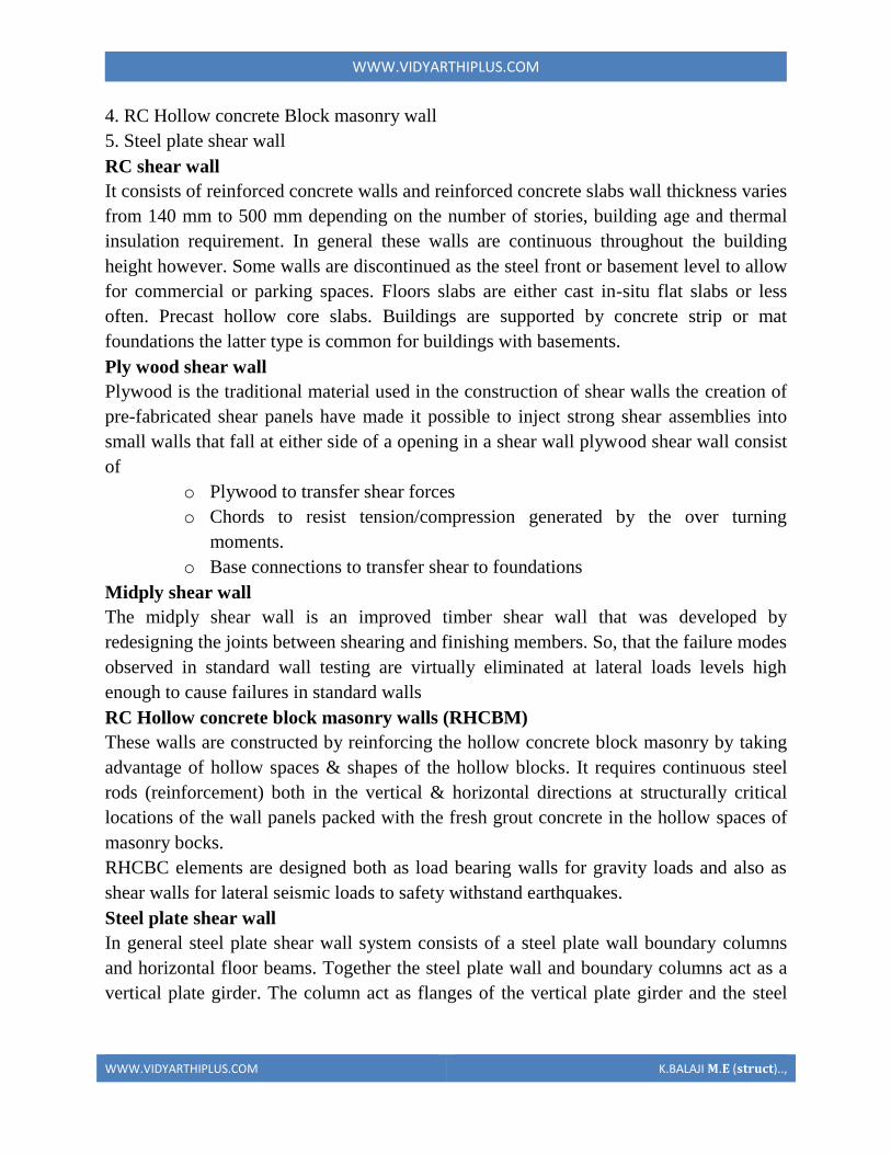
WWWVIDYARTHIPLUSCOM
WWWVIDYARTHIPLUSCOM KBALAJI 119820119812 (119852119853119851119854119836119853)
4 RC Hollow concrete Block masonry wall
5 Steel plate shear wall
RC shear wall
It consists of reinforced concrete walls and reinforced concrete slabs wall thickness varies
from 140 mm to 500 mm depending on the number of stories building age and thermal
insulation requirement In general these walls are continuous throughout the building
height however Some walls are discontinued as the steel front or basement level to allow
for commercial or parking spaces Floors slabs are either cast in-situ flat slabs or less
often Precast hollow core slabs Buildings are supported by concrete strip or mat
foundations the latter type is common for buildings with basements
Ply wood shear wall
Plywood is the traditional material used in the construction of shear walls the creation of
pre-fabricated shear panels have made it possible to inject strong shear assemblies into
small walls that fall at either side of a opening in a shear wall plywood shear wall consist
of
o Plywood to transfer shear forces
o Chords to resist tensioncompression generated by the over turning
moments
o Base connections to transfer shear to foundations
Midply shear wall
The midply shear wall is an improved timber shear wall that was developed by
redesigning the joints between shearing and finishing members So that the failure modes
observed in standard wall testing are virtually eliminated at lateral loads levels high
enough to cause failures in standard walls
RC Hollow concrete block masonry walls (RHCBM)
These walls are constructed by reinforcing the hollow concrete block masonry by taking
advantage of hollow spaces amp shapes of the hollow blocks It requires continuous steel
rods (reinforcement) both in the vertical amp horizontal directions at structurally critical
locations of the wall panels packed with the fresh grout concrete in the hollow spaces of
masonry bocks
RHCBC elements are designed both as load bearing walls for gravity loads and also as
shear walls for lateral seismic loads to safety withstand earthquakes
Steel plate shear wall
In general steel plate shear wall system consists of a steel plate wall boundary columns
and horizontal floor beams Together the steel plate wall and boundary columns act as a
vertical plate girder The column act as flanges of the vertical plate girder and the steel
WWWVIDYARTHIPLUSCOM
WWWVIDYARTHIPLUSCOM KBALAJI 119820119812 (119852119853119851119854119836119853)
plates wall act as its web The horizontal floor beams act more or less as transverse
stiffeners in a plate girder steel plate shear wall systems have been used in recent years in
highly seismic area to resist lateral loads
Thus shear walls are one of the most effective building elements in resisting lateral forces
during earthquake By constructing shear walls damages due to effect of lateral forces
due to earthquake and high winds can be minimized shear walls construction will provide
larger stiffness to the buildings there by reducing the damage to structure and its contents
Hence it is preferable to have all these prefabricate approximately of some weight very
near to the lifting capacity of the equipment
SHEAR WALL
WWWVIDYARTHIPLUSCOM
WWWVIDYARTHIPLUSCOM KBALAJI 119820119812 (119852119853119851119854119836119853)
WWWVIDYARTHIPLUSCOM
WWWVIDYARTHIPLUSCOM KBALAJI 119820119812 (119852119853119851119854119836119853)
WWWVIDYARTHIPLUSCOM
WWWVIDYARTHIPLUSCOM KBALAJI 119820119812 (119852119853119851119854119836119853)
Off-site fabrication
Off-Site fabrication is a process that incorporates prefabrication and pre-assembly The
process involves the design and manufacture of units or modules usually remote from the
work site and the installation at the site to form the permanent works at the site In its
fullest sense off-site fabrication requires a project strategy that will change the
orientation of the project process from construction to manufacture to installation
Examples of off-site fabrication are wall panels for homes wooden truss bridge spans
airport control stations
There are 4 main categories of Off-Site fabrication which is often also referred to as Off-
Site Construction These can be described as component (or sub-assembly) systems
penalized systems volumetric systems and modular systems Below these categories
different branches or technologies are being developed There are a vast number of
different systems on the market which fall into these categories and with recent advances
in digital design such as Building Information Modeling (BIM) the task of integrating
WWWVIDYARTHIPLUSCOM
WWWVIDYARTHIPLUSCOM KBALAJI 119820119812 (119852119853119851119854119836119853)
these different systems into a construction project is becoming increasingly a digital
management proposition
Unit -1
Question with answer
Part-A-
1Define prefabrication
The term prefab can apply to any construction method where the significant part of the
construction takes place off site in a factory That produces relatively large complex
features that assembled at the site into the finished building
2What is meant by modular Coordination
Modular coordination is a concept for coordinating dimension and space for which
building and component are dimensionally it used and positioned in basic units (or)
modules
The standard specify that the module basic M = 100 mm As the basic unit be used in a
square of M
3What are the characteristics of Modular concept
I) The basic module is small in terms of add size in order to provide design flexibility
yet large enough to promote simplification in the component variation in sizes
II) Industry friendly features that not only for manufacturing but also the transportation
and assembly requirements
III) Internationally accepted to support international market
4 Write out the advantages amp disadvantages of prefabrication
I) Self supporting readymade components are used so the need for formwork shuttering
and scaffolding is greatly reduced
II) On-site construction and condition is minimized
III) Less waste may occur
Disadvantages
I)Careful handling of prefabricated components such as concrete panels (or) steel and
glass Panels is reduced
II) Similarly leaks can form at joints is prefabricated component
5) Define the term Off-site fabrication
WWWVIDYARTHIPLUSCOM
WWWVIDYARTHIPLUSCOM KBALAJI 119820119812 (119852119853119851119854119836119853)
Off-site fabrication is the process that incorporates prefabrication and preassemble the
process involves the design and manufacture of units usually remote from the work site
and the installation at the site to form the permanent work at the site
6) Write short note on Production process
The production of concrete blocks consists of four basic process They are
1) Mixing
2) Moulding
3) Curing
4) Cubing
7) List out the limitations of prefabrication
I) Extra reinforcement is required to take care of handling and erection stresses
II) Temporary props may be required in some cases before the un-site concrete joints
achieve strength
III) The cracks may develop at the joints between the precart in ndashsite concrete due to
shrinkage and temperature stresses To overcome them extra steel is required across
joint
8) What are all the Prefab materials
Structural insulated panels (SIPs)
Insulating concrete forms (ICFS)
Prefab foundation system
Steel framing
Concrete framing
Large - modular system
9) Insulating concrete forms
Insulating concrete forms (ICE) are a prefab construction material consisting of hollow
EPS foam blocks that are stacked and glued together on-site creating the form that is
filled with reinforcing bars and concrete
10) Write short note on Principles of MC Concept
The principle objective of implanting MC is to improve productivity through the
reduction of wastages in the production installation process to improve quality in the
construction industry and to encourage an open system
WWWVIDYARTHIPLUSCOM
WWWVIDYARTHIPLUSCOM KBALAJI 119820119812 (119852119853119851119854119836119853)
11 Define shear wall
These are simple type and these shear walls under forces and horizontal shear along its
length are subjected to bending and shear To resist these forces the uniform
distribution of steel along its length is used in simple shear walls
12 Different classification of shear walls
1) Plain rectangular shear wall
2) Bar bell type
3) Framed shear wall
4) Coupled shear wall
5) Care type
13What is Modular Coordination
Modular coordination or MC is a dimensional system It is a dimension and space
coordination concept in which building and components are placed at their
designations based on the unit
14 How dimensional coordination is helpful in prefabricated structures
Building production is the organization and management of the plans equipment
materials and labour involved in the construction of a building while at the same time
complying with all codes rules and contractual stipulations The procedure should be
designed to run efficiently to keep the costs low and to allow returns on the
investment to be realized as early as possible
15 Explain the term basic module
Modular are terms that usually refer to upscale housing that can be any combination
of pre-engineered home parts that re delivered to the building site ready to be
assembled in a quick manner
16 What are the factors to consider in transporting of prefabricated structures
Transport device being movable from the input end to the output end of the production
line through a series of workstations said building unit being fabricated on an upper
surface of said flatbed said flatbed having an anti-friction surface on the upper surface
WWWVIDYARTHIPLUSCOM
WWWVIDYARTHIPLUSCOM KBALAJI 119820119812 (119852119853119851119854119836119853)
thereof for permitting sliding movement of said building unit relative to said transport
device
17 Explain the role of shear connectors in pre fabricated structures
Shear connectors may be spaced uniformly between the sections of maximum and zero
moment Shear connectors should have at least 1 in (254 mm) of concrete cover in all
directions and unless studs are located directly over the web stud diameters may not
exceed 25 times the beam-flange thickness With heavy concentrated loads the uniform
spacing of shear connectors may not be sufficient between a concentrated load and the
nearest point of zero moment
18 What are the special material properties in of prefabricated structures
Quicktoassemble
Cost-effective
Portablemovable
Strong
Water proof Moisture proof
Fire Resistant
19 What are the types of shear walls
Vertical Offset of Shear Walls
Stiffness shear wall
Steel shear wall
20 Write short notes on prefabrication
Prefabrication is the practice of assembling components of a structure in a factory or
other manufacturing site and transporting complete assemblies or sub-assemblies to
the construction site where the structure is to be located prefabrication in
architectural construction a technique whereby large units of a building are produced
WWWVIDYARTHIPLUSCOM
WWWVIDYARTHIPLUSCOM KBALAJI 119820119812 (119852119853119851119854119836119853)
in factories to be assembled ready-made on the building site The technique permits
the speedy erection of very large structures
21 Write any two advantages of prefabrication construction
Self-supporting ready-made components are used so the need for formwork
shuttering and scaffolding is greatly reduced
Construction time is reduced and buildings are completed sooner allowing an
earlier return of the capital invested
22 Define the term module
23 Write short notes on shear wall
A shear wall is a wall which is designed to resist shear the lateral force which causes
the bulk of damage in earthquakes
24 Write any two prefabrication problem of materials
Non availability of materials
Economy
25 Write the types of Derricks
A derrick is a lifting device composed of one mast or pole which is hinged freely at
the bottom It is controlled by lines powered by some means such as man-hauling or
motors so that the pole can move in all four directions
Hallen Derrick
Velle Derrick
Stuumllcken Derrick
26 What are the advantages of prefabricated structures
WWWVIDYARTHIPLUSCOM
WWWVIDYARTHIPLUSCOM KBALAJI 119820119812 (119852119853119851119854119836119853)
On-site construction and congestion is minimized
Quality control can be easier in a factory assembly line setting than a construction
site setting
Prefabrication can be located where skilled labour is more readily available and
costs of labour power materials space and overheads are lower
Time spent in bad weather or hazardous environments at the construction site is
minimised
27 What are the safety factors to be considered in designing
28 Explain about the location of shear wall
Lateral forces caused by wind earthquake and uneven settlement loads in addition to
the weight of structure and occupants create powerful twisting (torsional) forces
These forces can literally tear (shear) a building apart Reinforcing a frame by
attaching or placing a rigid wall inside it maintains the shape of the frame and
prevents rotation at the joints Shear walls are especially important in high-rise
buildings subject to lateral wind and seismic forces
29 What are the lateral loads in a building Live load
Wind load
Earthquake load 30What are the lateral load resisting elements in a building (AUC NovDec 2013) Vertical Elements
Moment
Resisting Frames
Walls
Bearing walls Shear Walls Structural Walls
Gravity Frame + Walls
ldquoDualrdquo System (Frame + Wall)
WWWVIDYARTHIPLUSCOM
WWWVIDYARTHIPLUSCOM KBALAJI 119820119812 (119852119853119851119854119836119853)
Vertical Truss
Tube System
Bundled
Tube System FloorDiaphragm
Foundation
WWWVIDYARTHIPLUSCOM
WWWVIDYARTHIPLUSCOM KBALAJI 119820119812 (119852119853119851119854119836119853)
Part-B
1Explain Modular Coordination in detail
Modular coordination means the interdependent arrangement of a dimension based on a
primary value accepted as a module The strict observance of rules of modular
coordination facilitated
1 Assembly of single components into large components
2 Fewest possible different types of component
3 Minimum wastage of cutting needed
Modular coordination is the basis for a standardization of a mass production of
component A
set of rules would be adequate for meeting the requirements of conventional and
prefabricated construction These rules are adaptable for
a The planning grid in both directions of the horizontal plan shall be
1 3M for residential and institutional buildings
2 For industrial buildings
WWWVIDYARTHIPLUSCOM
WWWVIDYARTHIPLUSCOM KBALAJI 119820119812 (119852119853119851119854119836119853)
15M for spans up to 12m
30M for spans between 12m and 18m
60M for spans over 18m
The centre lines of load bearing walls shall coincide with the grid lines
b In case of external walls the grid lines shall coincide with the centre line of the wall or
a line on the wall 5 cm from the internal face of the wall
C The planning module in the vertical direction shall be 1M up to and including a ht of
28M
d Preferred increments for the still heights doors windows and other fenestration shall
be
1M
e In case of internal columns the grid lines shall coincide with the centre lines of
columns In case of external columns the grid lines shall coincide with the centre lines of
the columns in the storey or a line in the column from the internal face of the column in
the topmost storey A basic module can be represented as module and for larger project
modules are represented a Mp
For eg For a project module in horizontal coordination the component can be of 30cm
and for vertical component size be of 10cm
The storey height is fixed between finished floor levels as 28m and if the thickness of
slab is lt15cm storey height is fixed as 27m The centre distance between the load
bearing walls can be chose from a set of modules The use of other dimensions is not
allowed
In the design of a building modular grid can be used consisting of parallel line spaced at
a value of module M or Mp and a grid line chosen as a base for setting out a part of a
building becomes a modular axis In the fig (a) a typical grid is chosen for load bearing
walls without duct The interior walls are placed so that their centre lines coincide with
the modular axis In the fig (b) a grid is shown for load bearing walls with hollow ducts
in between The centre line of the grid is found by deducting the size of duct
WWWVIDYARTHIPLUSCOM
WWWVIDYARTHIPLUSCOM KBALAJI 119820119812 (119852119853119851119854119836119853)
2Systems of prefabrication
System is referred to a particular method of construction of buildings using the
prefabricated components which are inter related in functions and are produced to a set of
instructions With certain constraints several plans are possible using the same set of
components the degree of flexibility varies from system to system However in all the
systems there is a certain order and discipline The system of prefabricated construction
depends on the extend of the use of prefab components their characteristics to be
considered in devising a system
i Intensified usage of spaces
ii Straight and simple walling scheme
iii Limited sizes and numbers of components
iv Limited opening in bearing walls
v Regulated locations of partitions
vi Standardized service and stair units
vii Limited sizes of doors and windows with regulated positions
viii Structural clarity and efficiency
ix Suitability for adoption in low rise and high rise blocks
x Ease of manufacturing storing and transporting
xi Speed and ease of erection
xii Simple jointing system
a) Based on Disuniting of member
b) Based on the construction
WWWVIDYARTHIPLUSCOM
WWWVIDYARTHIPLUSCOM KBALAJI 119820119812 (119852119853119851119854119836119853)
Based on Disuniting of member
1 System consisting of linear member disunited at joints
2 System for prefabricates of entire rigid frame
3 System consisting of ITU of straight members disunited at points of minimum
moment
4 Two hinged and three hinged arches
System consisting of linear member disunited at joints
Advantage
Disuniting at joints gives linear member This means that a great advantage and facilitates
from the view point manufacture and assembly
Disadvantage
1 Joints are at corners ie at points of maximum moment values so forming the joint is
difficult
2 Joints must be over dimensioned to cope with in-situ concreting And one alternate
solution to replace moment resistant joints by hinged connection
System for prefabricates of entire rigid frame
WWWVIDYARTHIPLUSCOM
WWWVIDYARTHIPLUSCOM KBALAJI 119820119812 (119852119853119851119854119836119853)
In this system to reduce the no of joints and to precast larger numbers I one piece leads
to the prefabrication of entire frame Production of the frames does not cause any
particular trouble but the hoisting is more difficult and requires careful preparation The
stress distribution of straight members during hoisting is in general statistically
determinate
Advantage
1 It is ideal for site prefabrication
2 Small number of joints so rapid prefabrication work is possible
3 Suitable for long walls consisting of great number of uniform frames
System consisting of ITU of straight members disunited at points of minimum
moment
WWWVIDYARTHIPLUSCOM
WWWVIDYARTHIPLUSCOM KBALAJI 119820119812 (119852119853119851119854119836119853)
WWWVIDYARTHIPLUSCOM
WWWVIDYARTHIPLUSCOM KBALAJI 119820119812 (119852119853119851119854119836119853)
Another method of disuniting of structures is by division into different membranes at
points where the moments are thin or smallest This method is called as lambda method
Using this method hinge joints are made
Advantage
1 Functions are made at points of minimum moments or at points of contra flexure
2 Disuniting the main girder in this manner makes the application of different skylights
possible
Disadvantage
1 Hosting and temperature bracing of L joined asymmetric frame members is
WWWVIDYARTHIPLUSCOM
WWWVIDYARTHIPLUSCOM KBALAJI 119820119812 (119852119853119851119854119836119853)
particularly complicated
2 Temperature resting of frame member on each other necessitates the use of
cantilevers having half depth and proper forming of this cause difficulty
Two hinged and three hinged arches
Arched structures are normally two hinged and three hinged arches Arched structures are
normally used for bridging span more than 20-25m Their production and placing is more
difficult than straight members Arch can be two hinged and three hinged but they can
also be fixed at footings and can be constructed with or without tie
These members are generally precast and assembled in statistically determinant three
hinged variance and middle hinge is only eliminated after placing is finished The
reinforcing bars protruding both sides are welded together and the joint between the
members is filled in with insitu concrete
Arch structure can be precast in either vertical or horizontal positions In the first case
shuttering made of timber or concrete is required having the same curvature s the arch
itself
The prefabrication of larger arches in the horizontal position is found to be more
economical
The construction of arch trusses can be properly carried out in the horizontal position
only
WWWVIDYARTHIPLUSCOM
WWWVIDYARTHIPLUSCOM KBALAJI 119820119812 (119852119853119851119854119836119853)
3Methods of prefabrication
Site prefabrication- for large prefabricates
Plant prefabrication- large scale production
Site prefabrication
1 The RC members are produced t the site in the open air chiefly in the open air or in
the temporary sheds
2 The difficulties in construction in general are felt in this mechanization can case
3 Mechanization cannot be of such high degree as site PF is done for smaller duration
of time
4 When the pre fabricates are of large size it is difficult to transport the pre fabricates to
the site
5 In comparison with plant prefabrication transportation of the members are not needed
As large members are not transported the design and weight of the prefabricates are not
limited
Plant prefabrication
1 The members produced are to be transported t the place of construction this accounts
for about 10-15 of the cost of production and assembling
2 Certain restriction is made in the dimension of prefabrication leading to restraints in
the design and development of prefabrication
3 Prefabrication is appropriate for mass production for manufacture of standardized
members
4 Needs costly materials for batching and production
5 This method is most suited in the case of small prefabricates which are to be
prefabricated in very large number
Plant prefabrication is done under permanent plant or factories It is done under the
covered roof so the effect of weather does not affect the work So the quality and strength
of the members can be improved considerably Plant prefabrication reduces the cost of
prefabrication if the number of prefabricate needed is more
Dimensions of prefabricate
There are 3 commonly known dimension for the prefabricates
1 The design of the erection dimension governing the dimensional coordination of the
prefabricates
2 Theoretical dimension
3 The actual dimension of the element when delivered the design dimension should be a
multiple of a basic module size m or of a module lap
WWWVIDYARTHIPLUSCOM
WWWVIDYARTHIPLUSCOM KBALAJI 119820119812 (119852119853119851119854119836119853)
Production of prefabricates
Production techniques involved are
1 Stand method
2 Conveyor method or line method
3 Aggregate method
Stand Method
In this method the prefabrication mature where they are moulded while the production
teams moves to successive stands The bed on which prefabricates are cast may be fixed
or
movable Tilting forms are often used and in this method steam curing is generally done
Conveyor belt method
The whole production is split up in to series operations carried out at separate successive
and permanent points served by specialized teams The movement of the mould or
prefabricate one point to other vary by means of conveyor belt trolleys
The rigid steel forms are assembled at station 1 where they are mould oil to reduce the
adhesion of concrete The conveyor moves front 1 to 2 where prestressing wires are fixed
amp in the next station anchoring of the wires is carried out The prepared mould is then
carried to the station 1ie casting station After casting it is shifted to the vibrating table amp
finally stacked station 5 for setting After that it is passed through tunnel autoclave for
curing After steam curing move too station 7 for demoulding amp is finally stacked 8
Aggregate method
In the aggregate method aggregate describes large complex permanently installed
machines amp mechanical appliances which carry out most of the separate operations
involved in the casting of the concrete composition The stand is operated by a permanent
team amp the only move the prefabricate makes is to the maturing point
Aggregate method is used in the production of multi duct hollow floor panel in Poland
At production point the reinforcement is fixed in the form amp remote controlled
aggregate(machine)inserts the duct formers castamp vibrates the concrete floats the top
of the floor The prepared prefabricate then move to the autoclave chamber in which
hardening of concrete is accelerate In many factories combined technology are employed
when complex prefabricate are required
Advantages
1The stand technique is the most flexible one It is used in varying degrees of
mechanization in all kinds of prefabricate factories
2It is simple amp less capital is required It can be used for field prefabricate also
WWWVIDYARTHIPLUSCOM
WWWVIDYARTHIPLUSCOM KBALAJI 119820119812 (119852119853119851119854119836119853)
3Aggregate method is used for large scale production in which case number of
machineries is required
4 Explain specific requirements in layout of of prefabricated plants
WWWVIDYARTHIPLUSCOM
WWWVIDYARTHIPLUSCOM KBALAJI 119820119812 (119852119853119851119854119836119853)
WWWVIDYARTHIPLUSCOM
WWWVIDYARTHIPLUSCOM KBALAJI 119820119812 (119852119853119851119854119836119853)
5 Explain with neat sketch of the types of shear wall
WWWVIDYARTHIPLUSCOM
WWWVIDYARTHIPLUSCOM KBALAJI 119820119812 (119852119853119851119854119836119853)
WWWVIDYARTHIPLUSCOM
WWWVIDYARTHIPLUSCOM KBALAJI 119820119812 (119852119853119851119854119836119853)
6 What is the code use for prefabricated structures
WWWVIDYARTHIPLUSCOM
WWWVIDYARTHIPLUSCOM KBALAJI 119820119812 (119852119853119851119854119836119853)
7 Explain in detail various design consideration in the design of precast construction
WWWVIDYARTHIPLUSCOM
WWWVIDYARTHIPLUSCOM KBALAJI 119820119812 (119852119853119851119854119836119853)
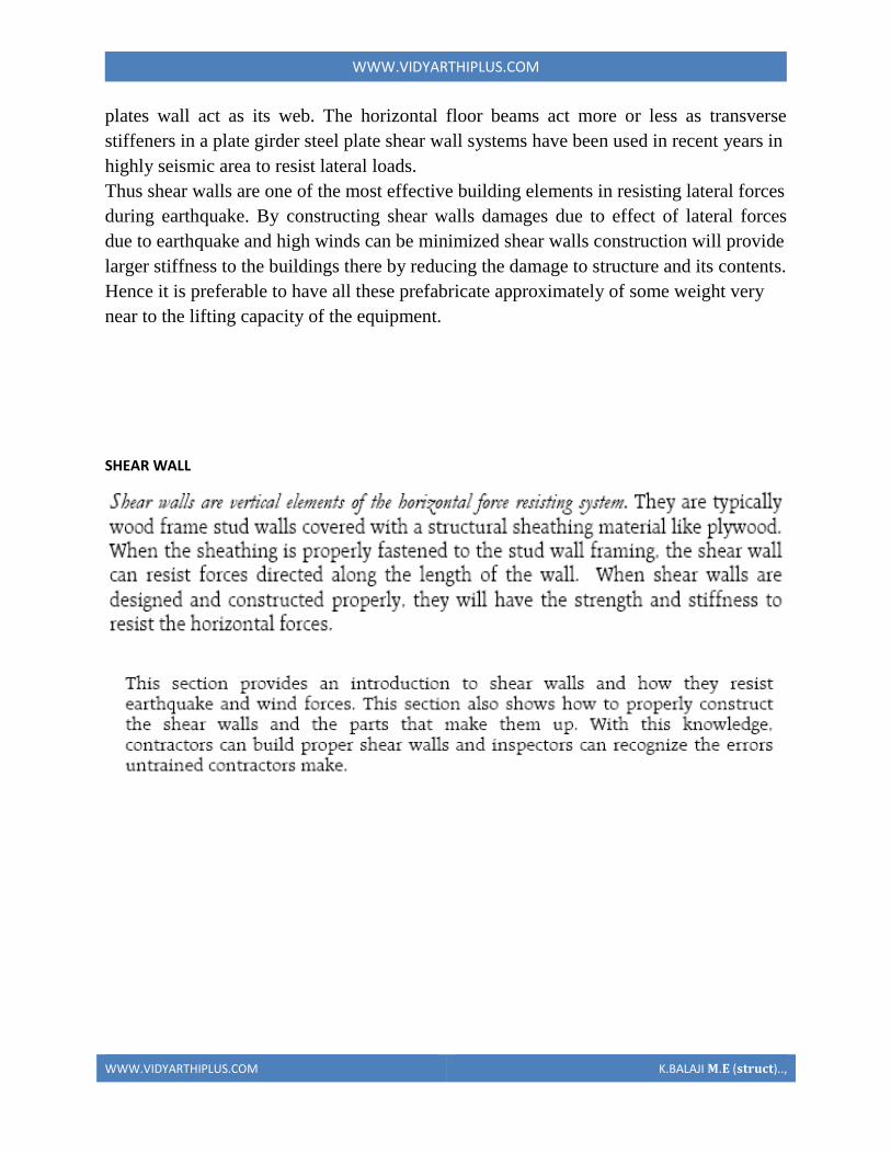
WWWVIDYARTHIPLUSCOM
WWWVIDYARTHIPLUSCOM KBALAJI 119820119812 (119852119853119851119854119836119853)
WWWVIDYARTHIPLUSCOM
WWWVIDYARTHIPLUSCOM KBALAJI 119820119812 (119852119853119851119854119836119853)
WWWVIDYARTHIPLUSCOM
WWWVIDYARTHIPLUSCOM KBALAJI 119820119812 (119852119853119851119854119836119853)
Off-site fabrication
Off-Site fabrication is a process that incorporates prefabrication and pre-assembly The
process involves the design and manufacture of units or modules usually remote from the
work site and the installation at the site to form the permanent works at the site In its
fullest sense off-site fabrication requires a project strategy that will change the
orientation of the project process from construction to manufacture to installation
Examples of off-site fabrication are wall panels for homes wooden truss bridge spans
airport control stations
There are 4 main categories of Off-Site fabrication which is often also referred to as Off-
Site Construction These can be described as component (or sub-assembly) systems
penalized systems volumetric systems and modular systems Below these categories
different branches or technologies are being developed There are a vast number of
different systems on the market which fall into these categories and with recent advances
in digital design such as Building Information Modeling (BIM) the task of integrating
WWWVIDYARTHIPLUSCOM
WWWVIDYARTHIPLUSCOM KBALAJI 119820119812 (119852119853119851119854119836119853)
these different systems into a construction project is becoming increasingly a digital
management proposition
Unit -1
Question with answer
Part-A-
1Define prefabrication
The term prefab can apply to any construction method where the significant part of the
construction takes place off site in a factory That produces relatively large complex
features that assembled at the site into the finished building
2What is meant by modular Coordination
Modular coordination is a concept for coordinating dimension and space for which
building and component are dimensionally it used and positioned in basic units (or)
modules
The standard specify that the module basic M = 100 mm As the basic unit be used in a
square of M
3What are the characteristics of Modular concept
I) The basic module is small in terms of add size in order to provide design flexibility
yet large enough to promote simplification in the component variation in sizes
II) Industry friendly features that not only for manufacturing but also the transportation
and assembly requirements
III) Internationally accepted to support international market
4 Write out the advantages amp disadvantages of prefabrication
I) Self supporting readymade components are used so the need for formwork shuttering
and scaffolding is greatly reduced
II) On-site construction and condition is minimized
III) Less waste may occur
Disadvantages
I)Careful handling of prefabricated components such as concrete panels (or) steel and
glass Panels is reduced
II) Similarly leaks can form at joints is prefabricated component
5) Define the term Off-site fabrication
WWWVIDYARTHIPLUSCOM
WWWVIDYARTHIPLUSCOM KBALAJI 119820119812 (119852119853119851119854119836119853)
Off-site fabrication is the process that incorporates prefabrication and preassemble the
process involves the design and manufacture of units usually remote from the work site
and the installation at the site to form the permanent work at the site
6) Write short note on Production process
The production of concrete blocks consists of four basic process They are
1) Mixing
2) Moulding
3) Curing
4) Cubing
7) List out the limitations of prefabrication
I) Extra reinforcement is required to take care of handling and erection stresses
II) Temporary props may be required in some cases before the un-site concrete joints
achieve strength
III) The cracks may develop at the joints between the precart in ndashsite concrete due to
shrinkage and temperature stresses To overcome them extra steel is required across
joint
8) What are all the Prefab materials
Structural insulated panels (SIPs)
Insulating concrete forms (ICFS)
Prefab foundation system
Steel framing
Concrete framing
Large - modular system
9) Insulating concrete forms
Insulating concrete forms (ICE) are a prefab construction material consisting of hollow
EPS foam blocks that are stacked and glued together on-site creating the form that is
filled with reinforcing bars and concrete
10) Write short note on Principles of MC Concept
The principle objective of implanting MC is to improve productivity through the
reduction of wastages in the production installation process to improve quality in the
construction industry and to encourage an open system
WWWVIDYARTHIPLUSCOM
WWWVIDYARTHIPLUSCOM KBALAJI 119820119812 (119852119853119851119854119836119853)
11 Define shear wall
These are simple type and these shear walls under forces and horizontal shear along its
length are subjected to bending and shear To resist these forces the uniform
distribution of steel along its length is used in simple shear walls
12 Different classification of shear walls
1) Plain rectangular shear wall
2) Bar bell type
3) Framed shear wall
4) Coupled shear wall
5) Care type
13What is Modular Coordination
Modular coordination or MC is a dimensional system It is a dimension and space
coordination concept in which building and components are placed at their
designations based on the unit
14 How dimensional coordination is helpful in prefabricated structures
Building production is the organization and management of the plans equipment
materials and labour involved in the construction of a building while at the same time
complying with all codes rules and contractual stipulations The procedure should be
designed to run efficiently to keep the costs low and to allow returns on the
investment to be realized as early as possible
15 Explain the term basic module
Modular are terms that usually refer to upscale housing that can be any combination
of pre-engineered home parts that re delivered to the building site ready to be
assembled in a quick manner
16 What are the factors to consider in transporting of prefabricated structures
Transport device being movable from the input end to the output end of the production
line through a series of workstations said building unit being fabricated on an upper
surface of said flatbed said flatbed having an anti-friction surface on the upper surface
WWWVIDYARTHIPLUSCOM
WWWVIDYARTHIPLUSCOM KBALAJI 119820119812 (119852119853119851119854119836119853)
thereof for permitting sliding movement of said building unit relative to said transport
device
17 Explain the role of shear connectors in pre fabricated structures
Shear connectors may be spaced uniformly between the sections of maximum and zero
moment Shear connectors should have at least 1 in (254 mm) of concrete cover in all
directions and unless studs are located directly over the web stud diameters may not
exceed 25 times the beam-flange thickness With heavy concentrated loads the uniform
spacing of shear connectors may not be sufficient between a concentrated load and the
nearest point of zero moment
18 What are the special material properties in of prefabricated structures
Quicktoassemble
Cost-effective
Portablemovable
Strong
Water proof Moisture proof
Fire Resistant
19 What are the types of shear walls
Vertical Offset of Shear Walls
Stiffness shear wall
Steel shear wall
20 Write short notes on prefabrication
Prefabrication is the practice of assembling components of a structure in a factory or
other manufacturing site and transporting complete assemblies or sub-assemblies to
the construction site where the structure is to be located prefabrication in
architectural construction a technique whereby large units of a building are produced
WWWVIDYARTHIPLUSCOM
WWWVIDYARTHIPLUSCOM KBALAJI 119820119812 (119852119853119851119854119836119853)
in factories to be assembled ready-made on the building site The technique permits
the speedy erection of very large structures
21 Write any two advantages of prefabrication construction
Self-supporting ready-made components are used so the need for formwork
shuttering and scaffolding is greatly reduced
Construction time is reduced and buildings are completed sooner allowing an
earlier return of the capital invested
22 Define the term module
23 Write short notes on shear wall
A shear wall is a wall which is designed to resist shear the lateral force which causes
the bulk of damage in earthquakes
24 Write any two prefabrication problem of materials
Non availability of materials
Economy
25 Write the types of Derricks
A derrick is a lifting device composed of one mast or pole which is hinged freely at
the bottom It is controlled by lines powered by some means such as man-hauling or
motors so that the pole can move in all four directions
Hallen Derrick
Velle Derrick
Stuumllcken Derrick
26 What are the advantages of prefabricated structures
WWWVIDYARTHIPLUSCOM
WWWVIDYARTHIPLUSCOM KBALAJI 119820119812 (119852119853119851119854119836119853)
On-site construction and congestion is minimized
Quality control can be easier in a factory assembly line setting than a construction
site setting
Prefabrication can be located where skilled labour is more readily available and
costs of labour power materials space and overheads are lower
Time spent in bad weather or hazardous environments at the construction site is
minimised
27 What are the safety factors to be considered in designing
28 Explain about the location of shear wall
Lateral forces caused by wind earthquake and uneven settlement loads in addition to
the weight of structure and occupants create powerful twisting (torsional) forces
These forces can literally tear (shear) a building apart Reinforcing a frame by
attaching or placing a rigid wall inside it maintains the shape of the frame and
prevents rotation at the joints Shear walls are especially important in high-rise
buildings subject to lateral wind and seismic forces
29 What are the lateral loads in a building Live load
Wind load
Earthquake load 30What are the lateral load resisting elements in a building (AUC NovDec 2013) Vertical Elements
Moment
Resisting Frames
Walls
Bearing walls Shear Walls Structural Walls
Gravity Frame + Walls
ldquoDualrdquo System (Frame + Wall)
WWWVIDYARTHIPLUSCOM
WWWVIDYARTHIPLUSCOM KBALAJI 119820119812 (119852119853119851119854119836119853)
Vertical Truss
Tube System
Bundled
Tube System FloorDiaphragm
Foundation
WWWVIDYARTHIPLUSCOM
WWWVIDYARTHIPLUSCOM KBALAJI 119820119812 (119852119853119851119854119836119853)
Part-B
1Explain Modular Coordination in detail
Modular coordination means the interdependent arrangement of a dimension based on a
primary value accepted as a module The strict observance of rules of modular
coordination facilitated
1 Assembly of single components into large components
2 Fewest possible different types of component
3 Minimum wastage of cutting needed
Modular coordination is the basis for a standardization of a mass production of
component A
set of rules would be adequate for meeting the requirements of conventional and
prefabricated construction These rules are adaptable for
a The planning grid in both directions of the horizontal plan shall be
1 3M for residential and institutional buildings
2 For industrial buildings
WWWVIDYARTHIPLUSCOM
WWWVIDYARTHIPLUSCOM KBALAJI 119820119812 (119852119853119851119854119836119853)
15M for spans up to 12m
30M for spans between 12m and 18m
60M for spans over 18m
The centre lines of load bearing walls shall coincide with the grid lines
b In case of external walls the grid lines shall coincide with the centre line of the wall or
a line on the wall 5 cm from the internal face of the wall
C The planning module in the vertical direction shall be 1M up to and including a ht of
28M
d Preferred increments for the still heights doors windows and other fenestration shall
be
1M
e In case of internal columns the grid lines shall coincide with the centre lines of
columns In case of external columns the grid lines shall coincide with the centre lines of
the columns in the storey or a line in the column from the internal face of the column in
the topmost storey A basic module can be represented as module and for larger project
modules are represented a Mp
For eg For a project module in horizontal coordination the component can be of 30cm
and for vertical component size be of 10cm
The storey height is fixed between finished floor levels as 28m and if the thickness of
slab is lt15cm storey height is fixed as 27m The centre distance between the load
bearing walls can be chose from a set of modules The use of other dimensions is not
allowed
In the design of a building modular grid can be used consisting of parallel line spaced at
a value of module M or Mp and a grid line chosen as a base for setting out a part of a
building becomes a modular axis In the fig (a) a typical grid is chosen for load bearing
walls without duct The interior walls are placed so that their centre lines coincide with
the modular axis In the fig (b) a grid is shown for load bearing walls with hollow ducts
in between The centre line of the grid is found by deducting the size of duct
WWWVIDYARTHIPLUSCOM
WWWVIDYARTHIPLUSCOM KBALAJI 119820119812 (119852119853119851119854119836119853)
2Systems of prefabrication
System is referred to a particular method of construction of buildings using the
prefabricated components which are inter related in functions and are produced to a set of
instructions With certain constraints several plans are possible using the same set of
components the degree of flexibility varies from system to system However in all the
systems there is a certain order and discipline The system of prefabricated construction
depends on the extend of the use of prefab components their characteristics to be
considered in devising a system
i Intensified usage of spaces
ii Straight and simple walling scheme
iii Limited sizes and numbers of components
iv Limited opening in bearing walls
v Regulated locations of partitions
vi Standardized service and stair units
vii Limited sizes of doors and windows with regulated positions
viii Structural clarity and efficiency
ix Suitability for adoption in low rise and high rise blocks
x Ease of manufacturing storing and transporting
xi Speed and ease of erection
xii Simple jointing system
a) Based on Disuniting of member
b) Based on the construction
WWWVIDYARTHIPLUSCOM
WWWVIDYARTHIPLUSCOM KBALAJI 119820119812 (119852119853119851119854119836119853)
Based on Disuniting of member
1 System consisting of linear member disunited at joints
2 System for prefabricates of entire rigid frame
3 System consisting of ITU of straight members disunited at points of minimum
moment
4 Two hinged and three hinged arches
System consisting of linear member disunited at joints
Advantage
Disuniting at joints gives linear member This means that a great advantage and facilitates
from the view point manufacture and assembly
Disadvantage
1 Joints are at corners ie at points of maximum moment values so forming the joint is
difficult
2 Joints must be over dimensioned to cope with in-situ concreting And one alternate
solution to replace moment resistant joints by hinged connection
System for prefabricates of entire rigid frame
WWWVIDYARTHIPLUSCOM
WWWVIDYARTHIPLUSCOM KBALAJI 119820119812 (119852119853119851119854119836119853)
In this system to reduce the no of joints and to precast larger numbers I one piece leads
to the prefabrication of entire frame Production of the frames does not cause any
particular trouble but the hoisting is more difficult and requires careful preparation The
stress distribution of straight members during hoisting is in general statistically
determinate
Advantage
1 It is ideal for site prefabrication
2 Small number of joints so rapid prefabrication work is possible
3 Suitable for long walls consisting of great number of uniform frames
System consisting of ITU of straight members disunited at points of minimum
moment
WWWVIDYARTHIPLUSCOM
WWWVIDYARTHIPLUSCOM KBALAJI 119820119812 (119852119853119851119854119836119853)
WWWVIDYARTHIPLUSCOM
WWWVIDYARTHIPLUSCOM KBALAJI 119820119812 (119852119853119851119854119836119853)
Another method of disuniting of structures is by division into different membranes at
points where the moments are thin or smallest This method is called as lambda method
Using this method hinge joints are made
Advantage
1 Functions are made at points of minimum moments or at points of contra flexure
2 Disuniting the main girder in this manner makes the application of different skylights
possible
Disadvantage
1 Hosting and temperature bracing of L joined asymmetric frame members is
WWWVIDYARTHIPLUSCOM
WWWVIDYARTHIPLUSCOM KBALAJI 119820119812 (119852119853119851119854119836119853)
particularly complicated
2 Temperature resting of frame member on each other necessitates the use of
cantilevers having half depth and proper forming of this cause difficulty
Two hinged and three hinged arches
Arched structures are normally two hinged and three hinged arches Arched structures are
normally used for bridging span more than 20-25m Their production and placing is more
difficult than straight members Arch can be two hinged and three hinged but they can
also be fixed at footings and can be constructed with or without tie
These members are generally precast and assembled in statistically determinant three
hinged variance and middle hinge is only eliminated after placing is finished The
reinforcing bars protruding both sides are welded together and the joint between the
members is filled in with insitu concrete
Arch structure can be precast in either vertical or horizontal positions In the first case
shuttering made of timber or concrete is required having the same curvature s the arch
itself
The prefabrication of larger arches in the horizontal position is found to be more
economical
The construction of arch trusses can be properly carried out in the horizontal position
only
WWWVIDYARTHIPLUSCOM
WWWVIDYARTHIPLUSCOM KBALAJI 119820119812 (119852119853119851119854119836119853)
3Methods of prefabrication
Site prefabrication- for large prefabricates
Plant prefabrication- large scale production
Site prefabrication
1 The RC members are produced t the site in the open air chiefly in the open air or in
the temporary sheds
2 The difficulties in construction in general are felt in this mechanization can case
3 Mechanization cannot be of such high degree as site PF is done for smaller duration
of time
4 When the pre fabricates are of large size it is difficult to transport the pre fabricates to
the site
5 In comparison with plant prefabrication transportation of the members are not needed
As large members are not transported the design and weight of the prefabricates are not
limited
Plant prefabrication
1 The members produced are to be transported t the place of construction this accounts
for about 10-15 of the cost of production and assembling
2 Certain restriction is made in the dimension of prefabrication leading to restraints in
the design and development of prefabrication
3 Prefabrication is appropriate for mass production for manufacture of standardized
members
4 Needs costly materials for batching and production
5 This method is most suited in the case of small prefabricates which are to be
prefabricated in very large number
Plant prefabrication is done under permanent plant or factories It is done under the
covered roof so the effect of weather does not affect the work So the quality and strength
of the members can be improved considerably Plant prefabrication reduces the cost of
prefabrication if the number of prefabricate needed is more
Dimensions of prefabricate
There are 3 commonly known dimension for the prefabricates
1 The design of the erection dimension governing the dimensional coordination of the
prefabricates
2 Theoretical dimension
3 The actual dimension of the element when delivered the design dimension should be a
multiple of a basic module size m or of a module lap
WWWVIDYARTHIPLUSCOM
WWWVIDYARTHIPLUSCOM KBALAJI 119820119812 (119852119853119851119854119836119853)
Production of prefabricates
Production techniques involved are
1 Stand method
2 Conveyor method or line method
3 Aggregate method
Stand Method
In this method the prefabrication mature where they are moulded while the production
teams moves to successive stands The bed on which prefabricates are cast may be fixed
or
movable Tilting forms are often used and in this method steam curing is generally done
Conveyor belt method
The whole production is split up in to series operations carried out at separate successive
and permanent points served by specialized teams The movement of the mould or
prefabricate one point to other vary by means of conveyor belt trolleys
The rigid steel forms are assembled at station 1 where they are mould oil to reduce the
adhesion of concrete The conveyor moves front 1 to 2 where prestressing wires are fixed
amp in the next station anchoring of the wires is carried out The prepared mould is then
carried to the station 1ie casting station After casting it is shifted to the vibrating table amp
finally stacked station 5 for setting After that it is passed through tunnel autoclave for
curing After steam curing move too station 7 for demoulding amp is finally stacked 8
Aggregate method
In the aggregate method aggregate describes large complex permanently installed
machines amp mechanical appliances which carry out most of the separate operations
involved in the casting of the concrete composition The stand is operated by a permanent
team amp the only move the prefabricate makes is to the maturing point
Aggregate method is used in the production of multi duct hollow floor panel in Poland
At production point the reinforcement is fixed in the form amp remote controlled
aggregate(machine)inserts the duct formers castamp vibrates the concrete floats the top
of the floor The prepared prefabricate then move to the autoclave chamber in which
hardening of concrete is accelerate In many factories combined technology are employed
when complex prefabricate are required
Advantages
1The stand technique is the most flexible one It is used in varying degrees of
mechanization in all kinds of prefabricate factories
2It is simple amp less capital is required It can be used for field prefabricate also
WWWVIDYARTHIPLUSCOM
WWWVIDYARTHIPLUSCOM KBALAJI 119820119812 (119852119853119851119854119836119853)
3Aggregate method is used for large scale production in which case number of
machineries is required
4 Explain specific requirements in layout of of prefabricated plants
WWWVIDYARTHIPLUSCOM
WWWVIDYARTHIPLUSCOM KBALAJI 119820119812 (119852119853119851119854119836119853)
WWWVIDYARTHIPLUSCOM
WWWVIDYARTHIPLUSCOM KBALAJI 119820119812 (119852119853119851119854119836119853)
5 Explain with neat sketch of the types of shear wall
WWWVIDYARTHIPLUSCOM
WWWVIDYARTHIPLUSCOM KBALAJI 119820119812 (119852119853119851119854119836119853)
WWWVIDYARTHIPLUSCOM
WWWVIDYARTHIPLUSCOM KBALAJI 119820119812 (119852119853119851119854119836119853)
6 What is the code use for prefabricated structures
WWWVIDYARTHIPLUSCOM
WWWVIDYARTHIPLUSCOM KBALAJI 119820119812 (119852119853119851119854119836119853)
7 Explain in detail various design consideration in the design of precast construction
WWWVIDYARTHIPLUSCOM
WWWVIDYARTHIPLUSCOM KBALAJI 119820119812 (119852119853119851119854119836119853)
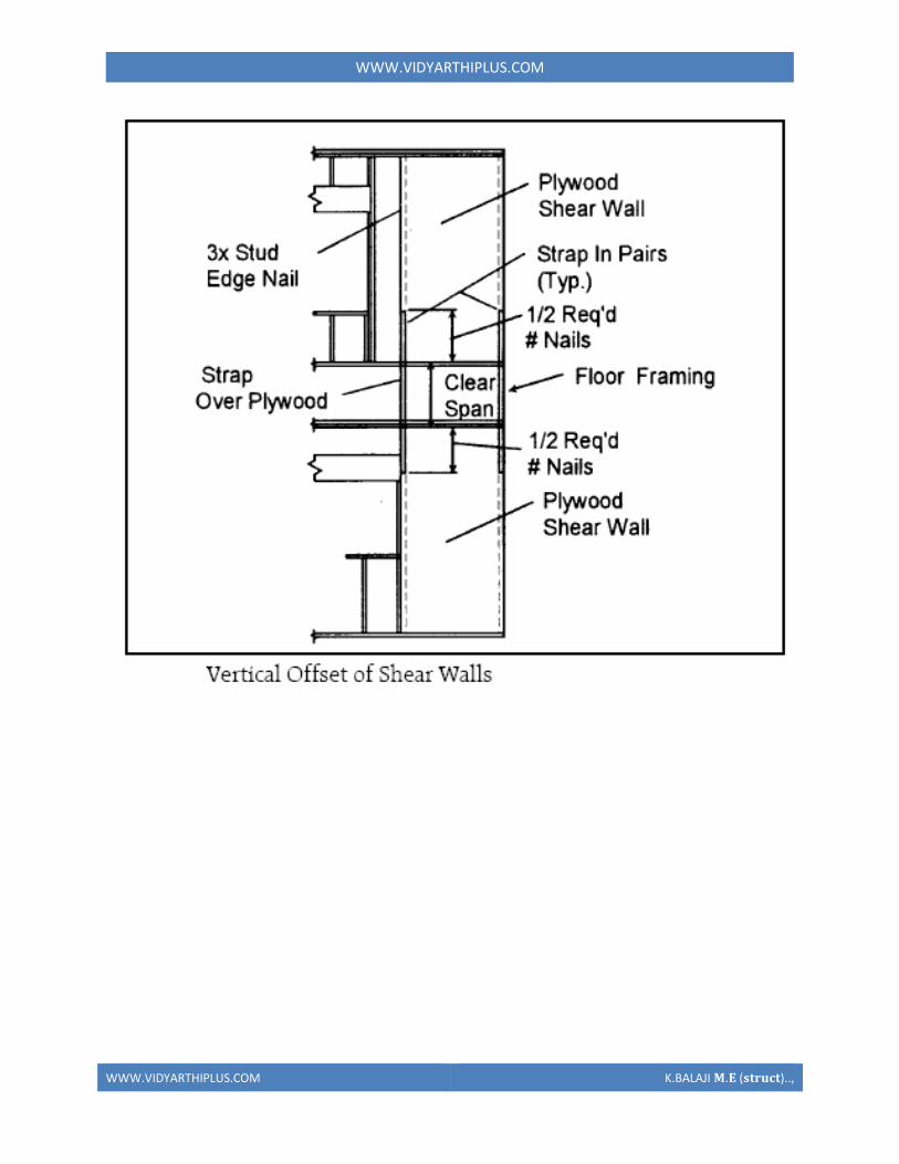
WWWVIDYARTHIPLUSCOM
WWWVIDYARTHIPLUSCOM KBALAJI 119820119812 (119852119853119851119854119836119853)
WWWVIDYARTHIPLUSCOM
WWWVIDYARTHIPLUSCOM KBALAJI 119820119812 (119852119853119851119854119836119853)
Off-site fabrication
Off-Site fabrication is a process that incorporates prefabrication and pre-assembly The
process involves the design and manufacture of units or modules usually remote from the
work site and the installation at the site to form the permanent works at the site In its
fullest sense off-site fabrication requires a project strategy that will change the
orientation of the project process from construction to manufacture to installation
Examples of off-site fabrication are wall panels for homes wooden truss bridge spans
airport control stations
There are 4 main categories of Off-Site fabrication which is often also referred to as Off-
Site Construction These can be described as component (or sub-assembly) systems
penalized systems volumetric systems and modular systems Below these categories
different branches or technologies are being developed There are a vast number of
different systems on the market which fall into these categories and with recent advances
in digital design such as Building Information Modeling (BIM) the task of integrating
WWWVIDYARTHIPLUSCOM
WWWVIDYARTHIPLUSCOM KBALAJI 119820119812 (119852119853119851119854119836119853)
these different systems into a construction project is becoming increasingly a digital
management proposition
Unit -1
Question with answer
Part-A-
1Define prefabrication
The term prefab can apply to any construction method where the significant part of the
construction takes place off site in a factory That produces relatively large complex
features that assembled at the site into the finished building
2What is meant by modular Coordination
Modular coordination is a concept for coordinating dimension and space for which
building and component are dimensionally it used and positioned in basic units (or)
modules
The standard specify that the module basic M = 100 mm As the basic unit be used in a
square of M
3What are the characteristics of Modular concept
I) The basic module is small in terms of add size in order to provide design flexibility
yet large enough to promote simplification in the component variation in sizes
II) Industry friendly features that not only for manufacturing but also the transportation
and assembly requirements
III) Internationally accepted to support international market
4 Write out the advantages amp disadvantages of prefabrication
I) Self supporting readymade components are used so the need for formwork shuttering
and scaffolding is greatly reduced
II) On-site construction and condition is minimized
III) Less waste may occur
Disadvantages
I)Careful handling of prefabricated components such as concrete panels (or) steel and
glass Panels is reduced
II) Similarly leaks can form at joints is prefabricated component
5) Define the term Off-site fabrication
WWWVIDYARTHIPLUSCOM
WWWVIDYARTHIPLUSCOM KBALAJI 119820119812 (119852119853119851119854119836119853)
Off-site fabrication is the process that incorporates prefabrication and preassemble the
process involves the design and manufacture of units usually remote from the work site
and the installation at the site to form the permanent work at the site
6) Write short note on Production process
The production of concrete blocks consists of four basic process They are
1) Mixing
2) Moulding
3) Curing
4) Cubing
7) List out the limitations of prefabrication
I) Extra reinforcement is required to take care of handling and erection stresses
II) Temporary props may be required in some cases before the un-site concrete joints
achieve strength
III) The cracks may develop at the joints between the precart in ndashsite concrete due to
shrinkage and temperature stresses To overcome them extra steel is required across
joint
8) What are all the Prefab materials
Structural insulated panels (SIPs)
Insulating concrete forms (ICFS)
Prefab foundation system
Steel framing
Concrete framing
Large - modular system
9) Insulating concrete forms
Insulating concrete forms (ICE) are a prefab construction material consisting of hollow
EPS foam blocks that are stacked and glued together on-site creating the form that is
filled with reinforcing bars and concrete
10) Write short note on Principles of MC Concept
The principle objective of implanting MC is to improve productivity through the
reduction of wastages in the production installation process to improve quality in the
construction industry and to encourage an open system
WWWVIDYARTHIPLUSCOM
WWWVIDYARTHIPLUSCOM KBALAJI 119820119812 (119852119853119851119854119836119853)
11 Define shear wall
These are simple type and these shear walls under forces and horizontal shear along its
length are subjected to bending and shear To resist these forces the uniform
distribution of steel along its length is used in simple shear walls
12 Different classification of shear walls
1) Plain rectangular shear wall
2) Bar bell type
3) Framed shear wall
4) Coupled shear wall
5) Care type
13What is Modular Coordination
Modular coordination or MC is a dimensional system It is a dimension and space
coordination concept in which building and components are placed at their
designations based on the unit
14 How dimensional coordination is helpful in prefabricated structures
Building production is the organization and management of the plans equipment
materials and labour involved in the construction of a building while at the same time
complying with all codes rules and contractual stipulations The procedure should be
designed to run efficiently to keep the costs low and to allow returns on the
investment to be realized as early as possible
15 Explain the term basic module
Modular are terms that usually refer to upscale housing that can be any combination
of pre-engineered home parts that re delivered to the building site ready to be
assembled in a quick manner
16 What are the factors to consider in transporting of prefabricated structures
Transport device being movable from the input end to the output end of the production
line through a series of workstations said building unit being fabricated on an upper
surface of said flatbed said flatbed having an anti-friction surface on the upper surface
WWWVIDYARTHIPLUSCOM
WWWVIDYARTHIPLUSCOM KBALAJI 119820119812 (119852119853119851119854119836119853)
thereof for permitting sliding movement of said building unit relative to said transport
device
17 Explain the role of shear connectors in pre fabricated structures
Shear connectors may be spaced uniformly between the sections of maximum and zero
moment Shear connectors should have at least 1 in (254 mm) of concrete cover in all
directions and unless studs are located directly over the web stud diameters may not
exceed 25 times the beam-flange thickness With heavy concentrated loads the uniform
spacing of shear connectors may not be sufficient between a concentrated load and the
nearest point of zero moment
18 What are the special material properties in of prefabricated structures
Quicktoassemble
Cost-effective
Portablemovable
Strong
Water proof Moisture proof
Fire Resistant
19 What are the types of shear walls
Vertical Offset of Shear Walls
Stiffness shear wall
Steel shear wall
20 Write short notes on prefabrication
Prefabrication is the practice of assembling components of a structure in a factory or
other manufacturing site and transporting complete assemblies or sub-assemblies to
the construction site where the structure is to be located prefabrication in
architectural construction a technique whereby large units of a building are produced
WWWVIDYARTHIPLUSCOM
WWWVIDYARTHIPLUSCOM KBALAJI 119820119812 (119852119853119851119854119836119853)
in factories to be assembled ready-made on the building site The technique permits
the speedy erection of very large structures
21 Write any two advantages of prefabrication construction
Self-supporting ready-made components are used so the need for formwork
shuttering and scaffolding is greatly reduced
Construction time is reduced and buildings are completed sooner allowing an
earlier return of the capital invested
22 Define the term module
23 Write short notes on shear wall
A shear wall is a wall which is designed to resist shear the lateral force which causes
the bulk of damage in earthquakes
24 Write any two prefabrication problem of materials
Non availability of materials
Economy
25 Write the types of Derricks
A derrick is a lifting device composed of one mast or pole which is hinged freely at
the bottom It is controlled by lines powered by some means such as man-hauling or
motors so that the pole can move in all four directions
Hallen Derrick
Velle Derrick
Stuumllcken Derrick
26 What are the advantages of prefabricated structures
WWWVIDYARTHIPLUSCOM
WWWVIDYARTHIPLUSCOM KBALAJI 119820119812 (119852119853119851119854119836119853)
On-site construction and congestion is minimized
Quality control can be easier in a factory assembly line setting than a construction
site setting
Prefabrication can be located where skilled labour is more readily available and
costs of labour power materials space and overheads are lower
Time spent in bad weather or hazardous environments at the construction site is
minimised
27 What are the safety factors to be considered in designing
28 Explain about the location of shear wall
Lateral forces caused by wind earthquake and uneven settlement loads in addition to
the weight of structure and occupants create powerful twisting (torsional) forces
These forces can literally tear (shear) a building apart Reinforcing a frame by
attaching or placing a rigid wall inside it maintains the shape of the frame and
prevents rotation at the joints Shear walls are especially important in high-rise
buildings subject to lateral wind and seismic forces
29 What are the lateral loads in a building Live load
Wind load
Earthquake load 30What are the lateral load resisting elements in a building (AUC NovDec 2013) Vertical Elements
Moment
Resisting Frames
Walls
Bearing walls Shear Walls Structural Walls
Gravity Frame + Walls
ldquoDualrdquo System (Frame + Wall)
WWWVIDYARTHIPLUSCOM
WWWVIDYARTHIPLUSCOM KBALAJI 119820119812 (119852119853119851119854119836119853)
Vertical Truss
Tube System
Bundled
Tube System FloorDiaphragm
Foundation
WWWVIDYARTHIPLUSCOM
WWWVIDYARTHIPLUSCOM KBALAJI 119820119812 (119852119853119851119854119836119853)
Part-B
1Explain Modular Coordination in detail
Modular coordination means the interdependent arrangement of a dimension based on a
primary value accepted as a module The strict observance of rules of modular
coordination facilitated
1 Assembly of single components into large components
2 Fewest possible different types of component
3 Minimum wastage of cutting needed
Modular coordination is the basis for a standardization of a mass production of
component A
set of rules would be adequate for meeting the requirements of conventional and
prefabricated construction These rules are adaptable for
a The planning grid in both directions of the horizontal plan shall be
1 3M for residential and institutional buildings
2 For industrial buildings
WWWVIDYARTHIPLUSCOM
WWWVIDYARTHIPLUSCOM KBALAJI 119820119812 (119852119853119851119854119836119853)
15M for spans up to 12m
30M for spans between 12m and 18m
60M for spans over 18m
The centre lines of load bearing walls shall coincide with the grid lines
b In case of external walls the grid lines shall coincide with the centre line of the wall or
a line on the wall 5 cm from the internal face of the wall
C The planning module in the vertical direction shall be 1M up to and including a ht of
28M
d Preferred increments for the still heights doors windows and other fenestration shall
be
1M
e In case of internal columns the grid lines shall coincide with the centre lines of
columns In case of external columns the grid lines shall coincide with the centre lines of
the columns in the storey or a line in the column from the internal face of the column in
the topmost storey A basic module can be represented as module and for larger project
modules are represented a Mp
For eg For a project module in horizontal coordination the component can be of 30cm
and for vertical component size be of 10cm
The storey height is fixed between finished floor levels as 28m and if the thickness of
slab is lt15cm storey height is fixed as 27m The centre distance between the load
bearing walls can be chose from a set of modules The use of other dimensions is not
allowed
In the design of a building modular grid can be used consisting of parallel line spaced at
a value of module M or Mp and a grid line chosen as a base for setting out a part of a
building becomes a modular axis In the fig (a) a typical grid is chosen for load bearing
walls without duct The interior walls are placed so that their centre lines coincide with
the modular axis In the fig (b) a grid is shown for load bearing walls with hollow ducts
in between The centre line of the grid is found by deducting the size of duct
WWWVIDYARTHIPLUSCOM
WWWVIDYARTHIPLUSCOM KBALAJI 119820119812 (119852119853119851119854119836119853)
2Systems of prefabrication
System is referred to a particular method of construction of buildings using the
prefabricated components which are inter related in functions and are produced to a set of
instructions With certain constraints several plans are possible using the same set of
components the degree of flexibility varies from system to system However in all the
systems there is a certain order and discipline The system of prefabricated construction
depends on the extend of the use of prefab components their characteristics to be
considered in devising a system
i Intensified usage of spaces
ii Straight and simple walling scheme
iii Limited sizes and numbers of components
iv Limited opening in bearing walls
v Regulated locations of partitions
vi Standardized service and stair units
vii Limited sizes of doors and windows with regulated positions
viii Structural clarity and efficiency
ix Suitability for adoption in low rise and high rise blocks
x Ease of manufacturing storing and transporting
xi Speed and ease of erection
xii Simple jointing system
a) Based on Disuniting of member
b) Based on the construction
WWWVIDYARTHIPLUSCOM
WWWVIDYARTHIPLUSCOM KBALAJI 119820119812 (119852119853119851119854119836119853)
Based on Disuniting of member
1 System consisting of linear member disunited at joints
2 System for prefabricates of entire rigid frame
3 System consisting of ITU of straight members disunited at points of minimum
moment
4 Two hinged and three hinged arches
System consisting of linear member disunited at joints
Advantage
Disuniting at joints gives linear member This means that a great advantage and facilitates
from the view point manufacture and assembly
Disadvantage
1 Joints are at corners ie at points of maximum moment values so forming the joint is
difficult
2 Joints must be over dimensioned to cope with in-situ concreting And one alternate
solution to replace moment resistant joints by hinged connection
System for prefabricates of entire rigid frame
WWWVIDYARTHIPLUSCOM
WWWVIDYARTHIPLUSCOM KBALAJI 119820119812 (119852119853119851119854119836119853)
In this system to reduce the no of joints and to precast larger numbers I one piece leads
to the prefabrication of entire frame Production of the frames does not cause any
particular trouble but the hoisting is more difficult and requires careful preparation The
stress distribution of straight members during hoisting is in general statistically
determinate
Advantage
1 It is ideal for site prefabrication
2 Small number of joints so rapid prefabrication work is possible
3 Suitable for long walls consisting of great number of uniform frames
System consisting of ITU of straight members disunited at points of minimum
moment
WWWVIDYARTHIPLUSCOM
WWWVIDYARTHIPLUSCOM KBALAJI 119820119812 (119852119853119851119854119836119853)
WWWVIDYARTHIPLUSCOM
WWWVIDYARTHIPLUSCOM KBALAJI 119820119812 (119852119853119851119854119836119853)
Another method of disuniting of structures is by division into different membranes at
points where the moments are thin or smallest This method is called as lambda method
Using this method hinge joints are made
Advantage
1 Functions are made at points of minimum moments or at points of contra flexure
2 Disuniting the main girder in this manner makes the application of different skylights
possible
Disadvantage
1 Hosting and temperature bracing of L joined asymmetric frame members is
WWWVIDYARTHIPLUSCOM
WWWVIDYARTHIPLUSCOM KBALAJI 119820119812 (119852119853119851119854119836119853)
particularly complicated
2 Temperature resting of frame member on each other necessitates the use of
cantilevers having half depth and proper forming of this cause difficulty
Two hinged and three hinged arches
Arched structures are normally two hinged and three hinged arches Arched structures are
normally used for bridging span more than 20-25m Their production and placing is more
difficult than straight members Arch can be two hinged and three hinged but they can
also be fixed at footings and can be constructed with or without tie
These members are generally precast and assembled in statistically determinant three
hinged variance and middle hinge is only eliminated after placing is finished The
reinforcing bars protruding both sides are welded together and the joint between the
members is filled in with insitu concrete
Arch structure can be precast in either vertical or horizontal positions In the first case
shuttering made of timber or concrete is required having the same curvature s the arch
itself
The prefabrication of larger arches in the horizontal position is found to be more
economical
The construction of arch trusses can be properly carried out in the horizontal position
only
WWWVIDYARTHIPLUSCOM
WWWVIDYARTHIPLUSCOM KBALAJI 119820119812 (119852119853119851119854119836119853)
3Methods of prefabrication
Site prefabrication- for large prefabricates
Plant prefabrication- large scale production
Site prefabrication
1 The RC members are produced t the site in the open air chiefly in the open air or in
the temporary sheds
2 The difficulties in construction in general are felt in this mechanization can case
3 Mechanization cannot be of such high degree as site PF is done for smaller duration
of time
4 When the pre fabricates are of large size it is difficult to transport the pre fabricates to
the site
5 In comparison with plant prefabrication transportation of the members are not needed
As large members are not transported the design and weight of the prefabricates are not
limited
Plant prefabrication
1 The members produced are to be transported t the place of construction this accounts
for about 10-15 of the cost of production and assembling
2 Certain restriction is made in the dimension of prefabrication leading to restraints in
the design and development of prefabrication
3 Prefabrication is appropriate for mass production for manufacture of standardized
members
4 Needs costly materials for batching and production
5 This method is most suited in the case of small prefabricates which are to be
prefabricated in very large number
Plant prefabrication is done under permanent plant or factories It is done under the
covered roof so the effect of weather does not affect the work So the quality and strength
of the members can be improved considerably Plant prefabrication reduces the cost of
prefabrication if the number of prefabricate needed is more
Dimensions of prefabricate
There are 3 commonly known dimension for the prefabricates
1 The design of the erection dimension governing the dimensional coordination of the
prefabricates
2 Theoretical dimension
3 The actual dimension of the element when delivered the design dimension should be a
multiple of a basic module size m or of a module lap
WWWVIDYARTHIPLUSCOM
WWWVIDYARTHIPLUSCOM KBALAJI 119820119812 (119852119853119851119854119836119853)
Production of prefabricates
Production techniques involved are
1 Stand method
2 Conveyor method or line method
3 Aggregate method
Stand Method
In this method the prefabrication mature where they are moulded while the production
teams moves to successive stands The bed on which prefabricates are cast may be fixed
or
movable Tilting forms are often used and in this method steam curing is generally done
Conveyor belt method
The whole production is split up in to series operations carried out at separate successive
and permanent points served by specialized teams The movement of the mould or
prefabricate one point to other vary by means of conveyor belt trolleys
The rigid steel forms are assembled at station 1 where they are mould oil to reduce the
adhesion of concrete The conveyor moves front 1 to 2 where prestressing wires are fixed
amp in the next station anchoring of the wires is carried out The prepared mould is then
carried to the station 1ie casting station After casting it is shifted to the vibrating table amp
finally stacked station 5 for setting After that it is passed through tunnel autoclave for
curing After steam curing move too station 7 for demoulding amp is finally stacked 8
Aggregate method
In the aggregate method aggregate describes large complex permanently installed
machines amp mechanical appliances which carry out most of the separate operations
involved in the casting of the concrete composition The stand is operated by a permanent
team amp the only move the prefabricate makes is to the maturing point
Aggregate method is used in the production of multi duct hollow floor panel in Poland
At production point the reinforcement is fixed in the form amp remote controlled
aggregate(machine)inserts the duct formers castamp vibrates the concrete floats the top
of the floor The prepared prefabricate then move to the autoclave chamber in which
hardening of concrete is accelerate In many factories combined technology are employed
when complex prefabricate are required
Advantages
1The stand technique is the most flexible one It is used in varying degrees of
mechanization in all kinds of prefabricate factories
2It is simple amp less capital is required It can be used for field prefabricate also
WWWVIDYARTHIPLUSCOM
WWWVIDYARTHIPLUSCOM KBALAJI 119820119812 (119852119853119851119854119836119853)
3Aggregate method is used for large scale production in which case number of
machineries is required
4 Explain specific requirements in layout of of prefabricated plants
WWWVIDYARTHIPLUSCOM
WWWVIDYARTHIPLUSCOM KBALAJI 119820119812 (119852119853119851119854119836119853)
WWWVIDYARTHIPLUSCOM
WWWVIDYARTHIPLUSCOM KBALAJI 119820119812 (119852119853119851119854119836119853)
5 Explain with neat sketch of the types of shear wall
WWWVIDYARTHIPLUSCOM
WWWVIDYARTHIPLUSCOM KBALAJI 119820119812 (119852119853119851119854119836119853)
WWWVIDYARTHIPLUSCOM
WWWVIDYARTHIPLUSCOM KBALAJI 119820119812 (119852119853119851119854119836119853)
6 What is the code use for prefabricated structures
WWWVIDYARTHIPLUSCOM
WWWVIDYARTHIPLUSCOM KBALAJI 119820119812 (119852119853119851119854119836119853)
7 Explain in detail various design consideration in the design of precast construction
WWWVIDYARTHIPLUSCOM
WWWVIDYARTHIPLUSCOM KBALAJI 119820119812 (119852119853119851119854119836119853)
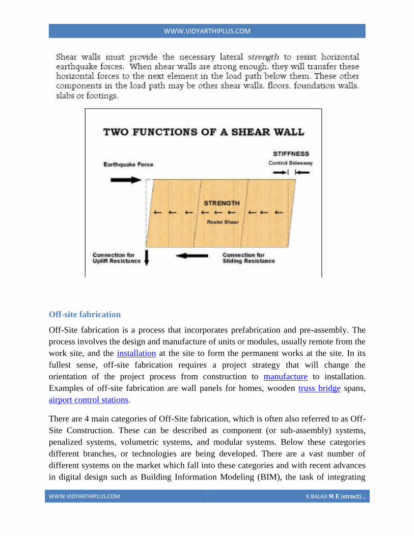
WWWVIDYARTHIPLUSCOM
WWWVIDYARTHIPLUSCOM KBALAJI 119820119812 (119852119853119851119854119836119853)
Off-site fabrication
Off-Site fabrication is a process that incorporates prefabrication and pre-assembly The
process involves the design and manufacture of units or modules usually remote from the
work site and the installation at the site to form the permanent works at the site In its
fullest sense off-site fabrication requires a project strategy that will change the
orientation of the project process from construction to manufacture to installation
Examples of off-site fabrication are wall panels for homes wooden truss bridge spans
airport control stations
There are 4 main categories of Off-Site fabrication which is often also referred to as Off-
Site Construction These can be described as component (or sub-assembly) systems
penalized systems volumetric systems and modular systems Below these categories
different branches or technologies are being developed There are a vast number of
different systems on the market which fall into these categories and with recent advances
in digital design such as Building Information Modeling (BIM) the task of integrating
WWWVIDYARTHIPLUSCOM
WWWVIDYARTHIPLUSCOM KBALAJI 119820119812 (119852119853119851119854119836119853)
these different systems into a construction project is becoming increasingly a digital
management proposition
Unit -1
Question with answer
Part-A-
1Define prefabrication
The term prefab can apply to any construction method where the significant part of the
construction takes place off site in a factory That produces relatively large complex
features that assembled at the site into the finished building
2What is meant by modular Coordination
Modular coordination is a concept for coordinating dimension and space for which
building and component are dimensionally it used and positioned in basic units (or)
modules
The standard specify that the module basic M = 100 mm As the basic unit be used in a
square of M
3What are the characteristics of Modular concept
I) The basic module is small in terms of add size in order to provide design flexibility
yet large enough to promote simplification in the component variation in sizes
II) Industry friendly features that not only for manufacturing but also the transportation
and assembly requirements
III) Internationally accepted to support international market
4 Write out the advantages amp disadvantages of prefabrication
I) Self supporting readymade components are used so the need for formwork shuttering
and scaffolding is greatly reduced
II) On-site construction and condition is minimized
III) Less waste may occur
Disadvantages
I)Careful handling of prefabricated components such as concrete panels (or) steel and
glass Panels is reduced
II) Similarly leaks can form at joints is prefabricated component
5) Define the term Off-site fabrication
WWWVIDYARTHIPLUSCOM
WWWVIDYARTHIPLUSCOM KBALAJI 119820119812 (119852119853119851119854119836119853)
Off-site fabrication is the process that incorporates prefabrication and preassemble the
process involves the design and manufacture of units usually remote from the work site
and the installation at the site to form the permanent work at the site
6) Write short note on Production process
The production of concrete blocks consists of four basic process They are
1) Mixing
2) Moulding
3) Curing
4) Cubing
7) List out the limitations of prefabrication
I) Extra reinforcement is required to take care of handling and erection stresses
II) Temporary props may be required in some cases before the un-site concrete joints
achieve strength
III) The cracks may develop at the joints between the precart in ndashsite concrete due to
shrinkage and temperature stresses To overcome them extra steel is required across
joint
8) What are all the Prefab materials
Structural insulated panels (SIPs)
Insulating concrete forms (ICFS)
Prefab foundation system
Steel framing
Concrete framing
Large - modular system
9) Insulating concrete forms
Insulating concrete forms (ICE) are a prefab construction material consisting of hollow
EPS foam blocks that are stacked and glued together on-site creating the form that is
filled with reinforcing bars and concrete
10) Write short note on Principles of MC Concept
The principle objective of implanting MC is to improve productivity through the
reduction of wastages in the production installation process to improve quality in the
construction industry and to encourage an open system
WWWVIDYARTHIPLUSCOM
WWWVIDYARTHIPLUSCOM KBALAJI 119820119812 (119852119853119851119854119836119853)
11 Define shear wall
These are simple type and these shear walls under forces and horizontal shear along its
length are subjected to bending and shear To resist these forces the uniform
distribution of steel along its length is used in simple shear walls
12 Different classification of shear walls
1) Plain rectangular shear wall
2) Bar bell type
3) Framed shear wall
4) Coupled shear wall
5) Care type
13What is Modular Coordination
Modular coordination or MC is a dimensional system It is a dimension and space
coordination concept in which building and components are placed at their
designations based on the unit
14 How dimensional coordination is helpful in prefabricated structures
Building production is the organization and management of the plans equipment
materials and labour involved in the construction of a building while at the same time
complying with all codes rules and contractual stipulations The procedure should be
designed to run efficiently to keep the costs low and to allow returns on the
investment to be realized as early as possible
15 Explain the term basic module
Modular are terms that usually refer to upscale housing that can be any combination
of pre-engineered home parts that re delivered to the building site ready to be
assembled in a quick manner
16 What are the factors to consider in transporting of prefabricated structures
Transport device being movable from the input end to the output end of the production
line through a series of workstations said building unit being fabricated on an upper
surface of said flatbed said flatbed having an anti-friction surface on the upper surface
WWWVIDYARTHIPLUSCOM
WWWVIDYARTHIPLUSCOM KBALAJI 119820119812 (119852119853119851119854119836119853)
thereof for permitting sliding movement of said building unit relative to said transport
device
17 Explain the role of shear connectors in pre fabricated structures
Shear connectors may be spaced uniformly between the sections of maximum and zero
moment Shear connectors should have at least 1 in (254 mm) of concrete cover in all
directions and unless studs are located directly over the web stud diameters may not
exceed 25 times the beam-flange thickness With heavy concentrated loads the uniform
spacing of shear connectors may not be sufficient between a concentrated load and the
nearest point of zero moment
18 What are the special material properties in of prefabricated structures
Quicktoassemble
Cost-effective
Portablemovable
Strong
Water proof Moisture proof
Fire Resistant
19 What are the types of shear walls
Vertical Offset of Shear Walls
Stiffness shear wall
Steel shear wall
20 Write short notes on prefabrication
Prefabrication is the practice of assembling components of a structure in a factory or
other manufacturing site and transporting complete assemblies or sub-assemblies to
the construction site where the structure is to be located prefabrication in
architectural construction a technique whereby large units of a building are produced
WWWVIDYARTHIPLUSCOM
WWWVIDYARTHIPLUSCOM KBALAJI 119820119812 (119852119853119851119854119836119853)
in factories to be assembled ready-made on the building site The technique permits
the speedy erection of very large structures
21 Write any two advantages of prefabrication construction
Self-supporting ready-made components are used so the need for formwork
shuttering and scaffolding is greatly reduced
Construction time is reduced and buildings are completed sooner allowing an
earlier return of the capital invested
22 Define the term module
23 Write short notes on shear wall
A shear wall is a wall which is designed to resist shear the lateral force which causes
the bulk of damage in earthquakes
24 Write any two prefabrication problem of materials
Non availability of materials
Economy
25 Write the types of Derricks
A derrick is a lifting device composed of one mast or pole which is hinged freely at
the bottom It is controlled by lines powered by some means such as man-hauling or
motors so that the pole can move in all four directions
Hallen Derrick
Velle Derrick
Stuumllcken Derrick
26 What are the advantages of prefabricated structures
WWWVIDYARTHIPLUSCOM
WWWVIDYARTHIPLUSCOM KBALAJI 119820119812 (119852119853119851119854119836119853)
On-site construction and congestion is minimized
Quality control can be easier in a factory assembly line setting than a construction
site setting
Prefabrication can be located where skilled labour is more readily available and
costs of labour power materials space and overheads are lower
Time spent in bad weather or hazardous environments at the construction site is
minimised
27 What are the safety factors to be considered in designing
28 Explain about the location of shear wall
Lateral forces caused by wind earthquake and uneven settlement loads in addition to
the weight of structure and occupants create powerful twisting (torsional) forces
These forces can literally tear (shear) a building apart Reinforcing a frame by
attaching or placing a rigid wall inside it maintains the shape of the frame and
prevents rotation at the joints Shear walls are especially important in high-rise
buildings subject to lateral wind and seismic forces
29 What are the lateral loads in a building Live load
Wind load
Earthquake load 30What are the lateral load resisting elements in a building (AUC NovDec 2013) Vertical Elements
Moment
Resisting Frames
Walls
Bearing walls Shear Walls Structural Walls
Gravity Frame + Walls
ldquoDualrdquo System (Frame + Wall)
WWWVIDYARTHIPLUSCOM
WWWVIDYARTHIPLUSCOM KBALAJI 119820119812 (119852119853119851119854119836119853)
Vertical Truss
Tube System
Bundled
Tube System FloorDiaphragm
Foundation
WWWVIDYARTHIPLUSCOM
WWWVIDYARTHIPLUSCOM KBALAJI 119820119812 (119852119853119851119854119836119853)
Part-B
1Explain Modular Coordination in detail
Modular coordination means the interdependent arrangement of a dimension based on a
primary value accepted as a module The strict observance of rules of modular
coordination facilitated
1 Assembly of single components into large components
2 Fewest possible different types of component
3 Minimum wastage of cutting needed
Modular coordination is the basis for a standardization of a mass production of
component A
set of rules would be adequate for meeting the requirements of conventional and
prefabricated construction These rules are adaptable for
a The planning grid in both directions of the horizontal plan shall be
1 3M for residential and institutional buildings
2 For industrial buildings
WWWVIDYARTHIPLUSCOM
WWWVIDYARTHIPLUSCOM KBALAJI 119820119812 (119852119853119851119854119836119853)
15M for spans up to 12m
30M for spans between 12m and 18m
60M for spans over 18m
The centre lines of load bearing walls shall coincide with the grid lines
b In case of external walls the grid lines shall coincide with the centre line of the wall or
a line on the wall 5 cm from the internal face of the wall
C The planning module in the vertical direction shall be 1M up to and including a ht of
28M
d Preferred increments for the still heights doors windows and other fenestration shall
be
1M
e In case of internal columns the grid lines shall coincide with the centre lines of
columns In case of external columns the grid lines shall coincide with the centre lines of
the columns in the storey or a line in the column from the internal face of the column in
the topmost storey A basic module can be represented as module and for larger project
modules are represented a Mp
For eg For a project module in horizontal coordination the component can be of 30cm
and for vertical component size be of 10cm
The storey height is fixed between finished floor levels as 28m and if the thickness of
slab is lt15cm storey height is fixed as 27m The centre distance between the load
bearing walls can be chose from a set of modules The use of other dimensions is not
allowed
In the design of a building modular grid can be used consisting of parallel line spaced at
a value of module M or Mp and a grid line chosen as a base for setting out a part of a
building becomes a modular axis In the fig (a) a typical grid is chosen for load bearing
walls without duct The interior walls are placed so that their centre lines coincide with
the modular axis In the fig (b) a grid is shown for load bearing walls with hollow ducts
in between The centre line of the grid is found by deducting the size of duct
WWWVIDYARTHIPLUSCOM
WWWVIDYARTHIPLUSCOM KBALAJI 119820119812 (119852119853119851119854119836119853)
2Systems of prefabrication
System is referred to a particular method of construction of buildings using the
prefabricated components which are inter related in functions and are produced to a set of
instructions With certain constraints several plans are possible using the same set of
components the degree of flexibility varies from system to system However in all the
systems there is a certain order and discipline The system of prefabricated construction
depends on the extend of the use of prefab components their characteristics to be
considered in devising a system
i Intensified usage of spaces
ii Straight and simple walling scheme
iii Limited sizes and numbers of components
iv Limited opening in bearing walls
v Regulated locations of partitions
vi Standardized service and stair units
vii Limited sizes of doors and windows with regulated positions
viii Structural clarity and efficiency
ix Suitability for adoption in low rise and high rise blocks
x Ease of manufacturing storing and transporting
xi Speed and ease of erection
xii Simple jointing system
a) Based on Disuniting of member
b) Based on the construction
WWWVIDYARTHIPLUSCOM
WWWVIDYARTHIPLUSCOM KBALAJI 119820119812 (119852119853119851119854119836119853)
Based on Disuniting of member
1 System consisting of linear member disunited at joints
2 System for prefabricates of entire rigid frame
3 System consisting of ITU of straight members disunited at points of minimum
moment
4 Two hinged and three hinged arches
System consisting of linear member disunited at joints
Advantage
Disuniting at joints gives linear member This means that a great advantage and facilitates
from the view point manufacture and assembly
Disadvantage
1 Joints are at corners ie at points of maximum moment values so forming the joint is
difficult
2 Joints must be over dimensioned to cope with in-situ concreting And one alternate
solution to replace moment resistant joints by hinged connection
System for prefabricates of entire rigid frame
WWWVIDYARTHIPLUSCOM
WWWVIDYARTHIPLUSCOM KBALAJI 119820119812 (119852119853119851119854119836119853)
In this system to reduce the no of joints and to precast larger numbers I one piece leads
to the prefabrication of entire frame Production of the frames does not cause any
particular trouble but the hoisting is more difficult and requires careful preparation The
stress distribution of straight members during hoisting is in general statistically
determinate
Advantage
1 It is ideal for site prefabrication
2 Small number of joints so rapid prefabrication work is possible
3 Suitable for long walls consisting of great number of uniform frames
System consisting of ITU of straight members disunited at points of minimum
moment
WWWVIDYARTHIPLUSCOM
WWWVIDYARTHIPLUSCOM KBALAJI 119820119812 (119852119853119851119854119836119853)
WWWVIDYARTHIPLUSCOM
WWWVIDYARTHIPLUSCOM KBALAJI 119820119812 (119852119853119851119854119836119853)
Another method of disuniting of structures is by division into different membranes at
points where the moments are thin or smallest This method is called as lambda method
Using this method hinge joints are made
Advantage
1 Functions are made at points of minimum moments or at points of contra flexure
2 Disuniting the main girder in this manner makes the application of different skylights
possible
Disadvantage
1 Hosting and temperature bracing of L joined asymmetric frame members is
WWWVIDYARTHIPLUSCOM
WWWVIDYARTHIPLUSCOM KBALAJI 119820119812 (119852119853119851119854119836119853)
particularly complicated
2 Temperature resting of frame member on each other necessitates the use of
cantilevers having half depth and proper forming of this cause difficulty
Two hinged and three hinged arches
Arched structures are normally two hinged and three hinged arches Arched structures are
normally used for bridging span more than 20-25m Their production and placing is more
difficult than straight members Arch can be two hinged and three hinged but they can
also be fixed at footings and can be constructed with or without tie
These members are generally precast and assembled in statistically determinant three
hinged variance and middle hinge is only eliminated after placing is finished The
reinforcing bars protruding both sides are welded together and the joint between the
members is filled in with insitu concrete
Arch structure can be precast in either vertical or horizontal positions In the first case
shuttering made of timber or concrete is required having the same curvature s the arch
itself
The prefabrication of larger arches in the horizontal position is found to be more
economical
The construction of arch trusses can be properly carried out in the horizontal position
only
WWWVIDYARTHIPLUSCOM
WWWVIDYARTHIPLUSCOM KBALAJI 119820119812 (119852119853119851119854119836119853)
3Methods of prefabrication
Site prefabrication- for large prefabricates
Plant prefabrication- large scale production
Site prefabrication
1 The RC members are produced t the site in the open air chiefly in the open air or in
the temporary sheds
2 The difficulties in construction in general are felt in this mechanization can case
3 Mechanization cannot be of such high degree as site PF is done for smaller duration
of time
4 When the pre fabricates are of large size it is difficult to transport the pre fabricates to
the site
5 In comparison with plant prefabrication transportation of the members are not needed
As large members are not transported the design and weight of the prefabricates are not
limited
Plant prefabrication
1 The members produced are to be transported t the place of construction this accounts
for about 10-15 of the cost of production and assembling
2 Certain restriction is made in the dimension of prefabrication leading to restraints in
the design and development of prefabrication
3 Prefabrication is appropriate for mass production for manufacture of standardized
members
4 Needs costly materials for batching and production
5 This method is most suited in the case of small prefabricates which are to be
prefabricated in very large number
Plant prefabrication is done under permanent plant or factories It is done under the
covered roof so the effect of weather does not affect the work So the quality and strength
of the members can be improved considerably Plant prefabrication reduces the cost of
prefabrication if the number of prefabricate needed is more
Dimensions of prefabricate
There are 3 commonly known dimension for the prefabricates
1 The design of the erection dimension governing the dimensional coordination of the
prefabricates
2 Theoretical dimension
3 The actual dimension of the element when delivered the design dimension should be a
multiple of a basic module size m or of a module lap
WWWVIDYARTHIPLUSCOM
WWWVIDYARTHIPLUSCOM KBALAJI 119820119812 (119852119853119851119854119836119853)
Production of prefabricates
Production techniques involved are
1 Stand method
2 Conveyor method or line method
3 Aggregate method
Stand Method
In this method the prefabrication mature where they are moulded while the production
teams moves to successive stands The bed on which prefabricates are cast may be fixed
or
movable Tilting forms are often used and in this method steam curing is generally done
Conveyor belt method
The whole production is split up in to series operations carried out at separate successive
and permanent points served by specialized teams The movement of the mould or
prefabricate one point to other vary by means of conveyor belt trolleys
The rigid steel forms are assembled at station 1 where they are mould oil to reduce the
adhesion of concrete The conveyor moves front 1 to 2 where prestressing wires are fixed
amp in the next station anchoring of the wires is carried out The prepared mould is then
carried to the station 1ie casting station After casting it is shifted to the vibrating table amp
finally stacked station 5 for setting After that it is passed through tunnel autoclave for
curing After steam curing move too station 7 for demoulding amp is finally stacked 8
Aggregate method
In the aggregate method aggregate describes large complex permanently installed
machines amp mechanical appliances which carry out most of the separate operations
involved in the casting of the concrete composition The stand is operated by a permanent
team amp the only move the prefabricate makes is to the maturing point
Aggregate method is used in the production of multi duct hollow floor panel in Poland
At production point the reinforcement is fixed in the form amp remote controlled
aggregate(machine)inserts the duct formers castamp vibrates the concrete floats the top
of the floor The prepared prefabricate then move to the autoclave chamber in which
hardening of concrete is accelerate In many factories combined technology are employed
when complex prefabricate are required
Advantages
1The stand technique is the most flexible one It is used in varying degrees of
mechanization in all kinds of prefabricate factories
2It is simple amp less capital is required It can be used for field prefabricate also
WWWVIDYARTHIPLUSCOM
WWWVIDYARTHIPLUSCOM KBALAJI 119820119812 (119852119853119851119854119836119853)
3Aggregate method is used for large scale production in which case number of
machineries is required
4 Explain specific requirements in layout of of prefabricated plants
WWWVIDYARTHIPLUSCOM
WWWVIDYARTHIPLUSCOM KBALAJI 119820119812 (119852119853119851119854119836119853)
WWWVIDYARTHIPLUSCOM
WWWVIDYARTHIPLUSCOM KBALAJI 119820119812 (119852119853119851119854119836119853)
5 Explain with neat sketch of the types of shear wall
WWWVIDYARTHIPLUSCOM
WWWVIDYARTHIPLUSCOM KBALAJI 119820119812 (119852119853119851119854119836119853)
WWWVIDYARTHIPLUSCOM
WWWVIDYARTHIPLUSCOM KBALAJI 119820119812 (119852119853119851119854119836119853)
6 What is the code use for prefabricated structures
WWWVIDYARTHIPLUSCOM
WWWVIDYARTHIPLUSCOM KBALAJI 119820119812 (119852119853119851119854119836119853)
7 Explain in detail various design consideration in the design of precast construction
WWWVIDYARTHIPLUSCOM
WWWVIDYARTHIPLUSCOM KBALAJI 119820119812 (119852119853119851119854119836119853)
WWWVIDYARTHIPLUSCOM
WWWVIDYARTHIPLUSCOM KBALAJI 119820119812 (119852119853119851119854119836119853)
Off-site fabrication is the process that incorporates prefabrication and preassemble the
process involves the design and manufacture of units usually remote from the work site
and the installation at the site to form the permanent work at the site
6) Write short note on Production process
The production of concrete blocks consists of four basic process They are
1) Mixing
2) Moulding
3) Curing
4) Cubing
7) List out the limitations of prefabrication
I) Extra reinforcement is required to take care of handling and erection stresses
II) Temporary props may be required in some cases before the un-site concrete joints
achieve strength
III) The cracks may develop at the joints between the precart in ndashsite concrete due to
shrinkage and temperature stresses To overcome them extra steel is required across
joint
8) What are all the Prefab materials
Structural insulated panels (SIPs)
Insulating concrete forms (ICFS)
Prefab foundation system
Steel framing
Concrete framing
Large - modular system
9) Insulating concrete forms
Insulating concrete forms (ICE) are a prefab construction material consisting of hollow
EPS foam blocks that are stacked and glued together on-site creating the form that is
filled with reinforcing bars and concrete
10) Write short note on Principles of MC Concept
The principle objective of implanting MC is to improve productivity through the
reduction of wastages in the production installation process to improve quality in the
construction industry and to encourage an open system
WWWVIDYARTHIPLUSCOM
WWWVIDYARTHIPLUSCOM KBALAJI 119820119812 (119852119853119851119854119836119853)
11 Define shear wall
These are simple type and these shear walls under forces and horizontal shear along its
length are subjected to bending and shear To resist these forces the uniform
distribution of steel along its length is used in simple shear walls
12 Different classification of shear walls
1) Plain rectangular shear wall
2) Bar bell type
3) Framed shear wall
4) Coupled shear wall
5) Care type
13What is Modular Coordination
Modular coordination or MC is a dimensional system It is a dimension and space
coordination concept in which building and components are placed at their
designations based on the unit
14 How dimensional coordination is helpful in prefabricated structures
Building production is the organization and management of the plans equipment
materials and labour involved in the construction of a building while at the same time
complying with all codes rules and contractual stipulations The procedure should be
designed to run efficiently to keep the costs low and to allow returns on the
investment to be realized as early as possible
15 Explain the term basic module
Modular are terms that usually refer to upscale housing that can be any combination
of pre-engineered home parts that re delivered to the building site ready to be
assembled in a quick manner
16 What are the factors to consider in transporting of prefabricated structures
Transport device being movable from the input end to the output end of the production
line through a series of workstations said building unit being fabricated on an upper
surface of said flatbed said flatbed having an anti-friction surface on the upper surface
WWWVIDYARTHIPLUSCOM
WWWVIDYARTHIPLUSCOM KBALAJI 119820119812 (119852119853119851119854119836119853)
thereof for permitting sliding movement of said building unit relative to said transport
device
17 Explain the role of shear connectors in pre fabricated structures
Shear connectors may be spaced uniformly between the sections of maximum and zero
moment Shear connectors should have at least 1 in (254 mm) of concrete cover in all
directions and unless studs are located directly over the web stud diameters may not
exceed 25 times the beam-flange thickness With heavy concentrated loads the uniform
spacing of shear connectors may not be sufficient between a concentrated load and the
nearest point of zero moment
18 What are the special material properties in of prefabricated structures
Quicktoassemble
Cost-effective
Portablemovable
Strong
Water proof Moisture proof
Fire Resistant
19 What are the types of shear walls
Vertical Offset of Shear Walls
Stiffness shear wall
Steel shear wall
20 Write short notes on prefabrication
Prefabrication is the practice of assembling components of a structure in a factory or
other manufacturing site and transporting complete assemblies or sub-assemblies to
the construction site where the structure is to be located prefabrication in
architectural construction a technique whereby large units of a building are produced
WWWVIDYARTHIPLUSCOM
WWWVIDYARTHIPLUSCOM KBALAJI 119820119812 (119852119853119851119854119836119853)
in factories to be assembled ready-made on the building site The technique permits
the speedy erection of very large structures
21 Write any two advantages of prefabrication construction
Self-supporting ready-made components are used so the need for formwork
shuttering and scaffolding is greatly reduced
Construction time is reduced and buildings are completed sooner allowing an
earlier return of the capital invested
22 Define the term module
23 Write short notes on shear wall
A shear wall is a wall which is designed to resist shear the lateral force which causes
the bulk of damage in earthquakes
24 Write any two prefabrication problem of materials
Non availability of materials
Economy
25 Write the types of Derricks
A derrick is a lifting device composed of one mast or pole which is hinged freely at
the bottom It is controlled by lines powered by some means such as man-hauling or
motors so that the pole can move in all four directions
Hallen Derrick
Velle Derrick
Stuumllcken Derrick
26 What are the advantages of prefabricated structures
WWWVIDYARTHIPLUSCOM
WWWVIDYARTHIPLUSCOM KBALAJI 119820119812 (119852119853119851119854119836119853)
On-site construction and congestion is minimized
Quality control can be easier in a factory assembly line setting than a construction
site setting
Prefabrication can be located where skilled labour is more readily available and
costs of labour power materials space and overheads are lower
Time spent in bad weather or hazardous environments at the construction site is
minimised
27 What are the safety factors to be considered in designing
28 Explain about the location of shear wall
Lateral forces caused by wind earthquake and uneven settlement loads in addition to
the weight of structure and occupants create powerful twisting (torsional) forces
These forces can literally tear (shear) a building apart Reinforcing a frame by
attaching or placing a rigid wall inside it maintains the shape of the frame and
prevents rotation at the joints Shear walls are especially important in high-rise
buildings subject to lateral wind and seismic forces
29 What are the lateral loads in a building Live load
Wind load
Earthquake load 30What are the lateral load resisting elements in a building (AUC NovDec 2013) Vertical Elements
Moment
Resisting Frames
Walls
Bearing walls Shear Walls Structural Walls
Gravity Frame + Walls
ldquoDualrdquo System (Frame + Wall)
WWWVIDYARTHIPLUSCOM
WWWVIDYARTHIPLUSCOM KBALAJI 119820119812 (119852119853119851119854119836119853)
Vertical Truss
Tube System
Bundled
Tube System FloorDiaphragm
Foundation
WWWVIDYARTHIPLUSCOM
WWWVIDYARTHIPLUSCOM KBALAJI 119820119812 (119852119853119851119854119836119853)
Part-B
1Explain Modular Coordination in detail
Modular coordination means the interdependent arrangement of a dimension based on a
primary value accepted as a module The strict observance of rules of modular
coordination facilitated
1 Assembly of single components into large components
2 Fewest possible different types of component
3 Minimum wastage of cutting needed
Modular coordination is the basis for a standardization of a mass production of
component A
set of rules would be adequate for meeting the requirements of conventional and
prefabricated construction These rules are adaptable for
a The planning grid in both directions of the horizontal plan shall be
1 3M for residential and institutional buildings
2 For industrial buildings
WWWVIDYARTHIPLUSCOM
WWWVIDYARTHIPLUSCOM KBALAJI 119820119812 (119852119853119851119854119836119853)
15M for spans up to 12m
30M for spans between 12m and 18m
60M for spans over 18m
The centre lines of load bearing walls shall coincide with the grid lines
b In case of external walls the grid lines shall coincide with the centre line of the wall or
a line on the wall 5 cm from the internal face of the wall
C The planning module in the vertical direction shall be 1M up to and including a ht of
28M
d Preferred increments for the still heights doors windows and other fenestration shall
be
1M
e In case of internal columns the grid lines shall coincide with the centre lines of
columns In case of external columns the grid lines shall coincide with the centre lines of
the columns in the storey or a line in the column from the internal face of the column in
the topmost storey A basic module can be represented as module and for larger project
modules are represented a Mp
For eg For a project module in horizontal coordination the component can be of 30cm
and for vertical component size be of 10cm
The storey height is fixed between finished floor levels as 28m and if the thickness of
slab is lt15cm storey height is fixed as 27m The centre distance between the load
bearing walls can be chose from a set of modules The use of other dimensions is not
allowed
In the design of a building modular grid can be used consisting of parallel line spaced at
a value of module M or Mp and a grid line chosen as a base for setting out a part of a
building becomes a modular axis In the fig (a) a typical grid is chosen for load bearing
walls without duct The interior walls are placed so that their centre lines coincide with
the modular axis In the fig (b) a grid is shown for load bearing walls with hollow ducts
in between The centre line of the grid is found by deducting the size of duct
WWWVIDYARTHIPLUSCOM
WWWVIDYARTHIPLUSCOM KBALAJI 119820119812 (119852119853119851119854119836119853)
2Systems of prefabrication
System is referred to a particular method of construction of buildings using the
prefabricated components which are inter related in functions and are produced to a set of
instructions With certain constraints several plans are possible using the same set of
components the degree of flexibility varies from system to system However in all the
systems there is a certain order and discipline The system of prefabricated construction
depends on the extend of the use of prefab components their characteristics to be
considered in devising a system
i Intensified usage of spaces
ii Straight and simple walling scheme
iii Limited sizes and numbers of components
iv Limited opening in bearing walls
v Regulated locations of partitions
vi Standardized service and stair units
vii Limited sizes of doors and windows with regulated positions
viii Structural clarity and efficiency
ix Suitability for adoption in low rise and high rise blocks
x Ease of manufacturing storing and transporting
xi Speed and ease of erection
xii Simple jointing system
a) Based on Disuniting of member
b) Based on the construction
WWWVIDYARTHIPLUSCOM
WWWVIDYARTHIPLUSCOM KBALAJI 119820119812 (119852119853119851119854119836119853)
Based on Disuniting of member
1 System consisting of linear member disunited at joints
2 System for prefabricates of entire rigid frame
3 System consisting of ITU of straight members disunited at points of minimum
moment
4 Two hinged and three hinged arches
System consisting of linear member disunited at joints
Advantage
Disuniting at joints gives linear member This means that a great advantage and facilitates
from the view point manufacture and assembly
Disadvantage
1 Joints are at corners ie at points of maximum moment values so forming the joint is
difficult
2 Joints must be over dimensioned to cope with in-situ concreting And one alternate
solution to replace moment resistant joints by hinged connection
System for prefabricates of entire rigid frame
WWWVIDYARTHIPLUSCOM
WWWVIDYARTHIPLUSCOM KBALAJI 119820119812 (119852119853119851119854119836119853)
In this system to reduce the no of joints and to precast larger numbers I one piece leads
to the prefabrication of entire frame Production of the frames does not cause any
particular trouble but the hoisting is more difficult and requires careful preparation The
stress distribution of straight members during hoisting is in general statistically
determinate
Advantage
1 It is ideal for site prefabrication
2 Small number of joints so rapid prefabrication work is possible
3 Suitable for long walls consisting of great number of uniform frames
System consisting of ITU of straight members disunited at points of minimum
moment
WWWVIDYARTHIPLUSCOM
WWWVIDYARTHIPLUSCOM KBALAJI 119820119812 (119852119853119851119854119836119853)
WWWVIDYARTHIPLUSCOM
WWWVIDYARTHIPLUSCOM KBALAJI 119820119812 (119852119853119851119854119836119853)
Another method of disuniting of structures is by division into different membranes at
points where the moments are thin or smallest This method is called as lambda method
Using this method hinge joints are made
Advantage
1 Functions are made at points of minimum moments or at points of contra flexure
2 Disuniting the main girder in this manner makes the application of different skylights
possible
Disadvantage
1 Hosting and temperature bracing of L joined asymmetric frame members is
WWWVIDYARTHIPLUSCOM
WWWVIDYARTHIPLUSCOM KBALAJI 119820119812 (119852119853119851119854119836119853)
particularly complicated
2 Temperature resting of frame member on each other necessitates the use of
cantilevers having half depth and proper forming of this cause difficulty
Two hinged and three hinged arches
Arched structures are normally two hinged and three hinged arches Arched structures are
normally used for bridging span more than 20-25m Their production and placing is more
difficult than straight members Arch can be two hinged and three hinged but they can
also be fixed at footings and can be constructed with or without tie
These members are generally precast and assembled in statistically determinant three
hinged variance and middle hinge is only eliminated after placing is finished The
reinforcing bars protruding both sides are welded together and the joint between the
members is filled in with insitu concrete
Arch structure can be precast in either vertical or horizontal positions In the first case
shuttering made of timber or concrete is required having the same curvature s the arch
itself
The prefabrication of larger arches in the horizontal position is found to be more
economical
The construction of arch trusses can be properly carried out in the horizontal position
only
WWWVIDYARTHIPLUSCOM
WWWVIDYARTHIPLUSCOM KBALAJI 119820119812 (119852119853119851119854119836119853)
3Methods of prefabrication
Site prefabrication- for large prefabricates
Plant prefabrication- large scale production
Site prefabrication
1 The RC members are produced t the site in the open air chiefly in the open air or in
the temporary sheds
2 The difficulties in construction in general are felt in this mechanization can case
3 Mechanization cannot be of such high degree as site PF is done for smaller duration
of time
4 When the pre fabricates are of large size it is difficult to transport the pre fabricates to
the site
5 In comparison with plant prefabrication transportation of the members are not needed
As large members are not transported the design and weight of the prefabricates are not
limited
Plant prefabrication
1 The members produced are to be transported t the place of construction this accounts
for about 10-15 of the cost of production and assembling
2 Certain restriction is made in the dimension of prefabrication leading to restraints in
the design and development of prefabrication
3 Prefabrication is appropriate for mass production for manufacture of standardized
members
4 Needs costly materials for batching and production
5 This method is most suited in the case of small prefabricates which are to be
prefabricated in very large number
Plant prefabrication is done under permanent plant or factories It is done under the
covered roof so the effect of weather does not affect the work So the quality and strength
of the members can be improved considerably Plant prefabrication reduces the cost of
prefabrication if the number of prefabricate needed is more
Dimensions of prefabricate
There are 3 commonly known dimension for the prefabricates
1 The design of the erection dimension governing the dimensional coordination of the
prefabricates
2 Theoretical dimension
3 The actual dimension of the element when delivered the design dimension should be a
multiple of a basic module size m or of a module lap
WWWVIDYARTHIPLUSCOM
WWWVIDYARTHIPLUSCOM KBALAJI 119820119812 (119852119853119851119854119836119853)
Production of prefabricates
Production techniques involved are
1 Stand method
2 Conveyor method or line method
3 Aggregate method
Stand Method
In this method the prefabrication mature where they are moulded while the production
teams moves to successive stands The bed on which prefabricates are cast may be fixed
or
movable Tilting forms are often used and in this method steam curing is generally done
Conveyor belt method
The whole production is split up in to series operations carried out at separate successive
and permanent points served by specialized teams The movement of the mould or
prefabricate one point to other vary by means of conveyor belt trolleys
The rigid steel forms are assembled at station 1 where they are mould oil to reduce the
adhesion of concrete The conveyor moves front 1 to 2 where prestressing wires are fixed
amp in the next station anchoring of the wires is carried out The prepared mould is then
carried to the station 1ie casting station After casting it is shifted to the vibrating table amp
finally stacked station 5 for setting After that it is passed through tunnel autoclave for
curing After steam curing move too station 7 for demoulding amp is finally stacked 8
Aggregate method
In the aggregate method aggregate describes large complex permanently installed
machines amp mechanical appliances which carry out most of the separate operations
involved in the casting of the concrete composition The stand is operated by a permanent
team amp the only move the prefabricate makes is to the maturing point
Aggregate method is used in the production of multi duct hollow floor panel in Poland
At production point the reinforcement is fixed in the form amp remote controlled
aggregate(machine)inserts the duct formers castamp vibrates the concrete floats the top
of the floor The prepared prefabricate then move to the autoclave chamber in which
hardening of concrete is accelerate In many factories combined technology are employed
when complex prefabricate are required
Advantages
1The stand technique is the most flexible one It is used in varying degrees of
mechanization in all kinds of prefabricate factories
2It is simple amp less capital is required It can be used for field prefabricate also
WWWVIDYARTHIPLUSCOM
WWWVIDYARTHIPLUSCOM KBALAJI 119820119812 (119852119853119851119854119836119853)
3Aggregate method is used for large scale production in which case number of
machineries is required
4 Explain specific requirements in layout of of prefabricated plants
WWWVIDYARTHIPLUSCOM
WWWVIDYARTHIPLUSCOM KBALAJI 119820119812 (119852119853119851119854119836119853)
WWWVIDYARTHIPLUSCOM
WWWVIDYARTHIPLUSCOM KBALAJI 119820119812 (119852119853119851119854119836119853)
5 Explain with neat sketch of the types of shear wall
WWWVIDYARTHIPLUSCOM
WWWVIDYARTHIPLUSCOM KBALAJI 119820119812 (119852119853119851119854119836119853)
WWWVIDYARTHIPLUSCOM
WWWVIDYARTHIPLUSCOM KBALAJI 119820119812 (119852119853119851119854119836119853)
6 What is the code use for prefabricated structures
WWWVIDYARTHIPLUSCOM
WWWVIDYARTHIPLUSCOM KBALAJI 119820119812 (119852119853119851119854119836119853)
7 Explain in detail various design consideration in the design of precast construction
WWWVIDYARTHIPLUSCOM
WWWVIDYARTHIPLUSCOM KBALAJI 119820119812 (119852119853119851119854119836119853)

WWWVIDYARTHIPLUSCOM
WWWVIDYARTHIPLUSCOM KBALAJI 119820119812 (119852119853119851119854119836119853)
On-site construction and congestion is minimized
Quality control can be easier in a factory assembly line setting than a construction
site setting
Prefabrication can be located where skilled labour is more readily available and
costs of labour power materials space and overheads are lower
Time spent in bad weather or hazardous environments at the construction site is
minimised
27 What are the safety factors to be considered in designing
28 Explain about the location of shear wall
Lateral forces caused by wind earthquake and uneven settlement loads in addition to
the weight of structure and occupants create powerful twisting (torsional) forces
These forces can literally tear (shear) a building apart Reinforcing a frame by
attaching or placing a rigid wall inside it maintains the shape of the frame and
prevents rotation at the joints Shear walls are especially important in high-rise
buildings subject to lateral wind and seismic forces
29 What are the lateral loads in a building Live load
Wind load
Earthquake load 30What are the lateral load resisting elements in a building (AUC NovDec 2013) Vertical Elements
Moment
Resisting Frames
Walls
Bearing walls Shear Walls Structural Walls
Gravity Frame + Walls
ldquoDualrdquo System (Frame + Wall)
WWWVIDYARTHIPLUSCOM
WWWVIDYARTHIPLUSCOM KBALAJI 119820119812 (119852119853119851119854119836119853)
Vertical Truss
Tube System
Bundled
Tube System FloorDiaphragm
Foundation
WWWVIDYARTHIPLUSCOM
WWWVIDYARTHIPLUSCOM KBALAJI 119820119812 (119852119853119851119854119836119853)
Part-B
1Explain Modular Coordination in detail
Modular coordination means the interdependent arrangement of a dimension based on a
primary value accepted as a module The strict observance of rules of modular
coordination facilitated
1 Assembly of single components into large components
2 Fewest possible different types of component
3 Minimum wastage of cutting needed
Modular coordination is the basis for a standardization of a mass production of
component A
set of rules would be adequate for meeting the requirements of conventional and
prefabricated construction These rules are adaptable for
a The planning grid in both directions of the horizontal plan shall be
1 3M for residential and institutional buildings
2 For industrial buildings
WWWVIDYARTHIPLUSCOM
WWWVIDYARTHIPLUSCOM KBALAJI 119820119812 (119852119853119851119854119836119853)
15M for spans up to 12m
30M for spans between 12m and 18m
60M for spans over 18m
The centre lines of load bearing walls shall coincide with the grid lines
b In case of external walls the grid lines shall coincide with the centre line of the wall or
a line on the wall 5 cm from the internal face of the wall
C The planning module in the vertical direction shall be 1M up to and including a ht of
28M
d Preferred increments for the still heights doors windows and other fenestration shall
be
1M
e In case of internal columns the grid lines shall coincide with the centre lines of
columns In case of external columns the grid lines shall coincide with the centre lines of
the columns in the storey or a line in the column from the internal face of the column in
the topmost storey A basic module can be represented as module and for larger project
modules are represented a Mp
For eg For a project module in horizontal coordination the component can be of 30cm
and for vertical component size be of 10cm
The storey height is fixed between finished floor levels as 28m and if the thickness of
slab is lt15cm storey height is fixed as 27m The centre distance between the load
bearing walls can be chose from a set of modules The use of other dimensions is not
allowed
In the design of a building modular grid can be used consisting of parallel line spaced at
a value of module M or Mp and a grid line chosen as a base for setting out a part of a
building becomes a modular axis In the fig (a) a typical grid is chosen for load bearing
walls without duct The interior walls are placed so that their centre lines coincide with
the modular axis In the fig (b) a grid is shown for load bearing walls with hollow ducts
in between The centre line of the grid is found by deducting the size of duct
WWWVIDYARTHIPLUSCOM
WWWVIDYARTHIPLUSCOM KBALAJI 119820119812 (119852119853119851119854119836119853)
2Systems of prefabrication
System is referred to a particular method of construction of buildings using the
prefabricated components which are inter related in functions and are produced to a set of
instructions With certain constraints several plans are possible using the same set of
components the degree of flexibility varies from system to system However in all the
systems there is a certain order and discipline The system of prefabricated construction
depends on the extend of the use of prefab components their characteristics to be
considered in devising a system
i Intensified usage of spaces
ii Straight and simple walling scheme
iii Limited sizes and numbers of components
iv Limited opening in bearing walls
v Regulated locations of partitions
vi Standardized service and stair units
vii Limited sizes of doors and windows with regulated positions
viii Structural clarity and efficiency
ix Suitability for adoption in low rise and high rise blocks
x Ease of manufacturing storing and transporting
xi Speed and ease of erection
xii Simple jointing system
a) Based on Disuniting of member
b) Based on the construction
WWWVIDYARTHIPLUSCOM
WWWVIDYARTHIPLUSCOM KBALAJI 119820119812 (119852119853119851119854119836119853)
Based on Disuniting of member
1 System consisting of linear member disunited at joints
2 System for prefabricates of entire rigid frame
3 System consisting of ITU of straight members disunited at points of minimum
moment
4 Two hinged and three hinged arches
System consisting of linear member disunited at joints
Advantage
Disuniting at joints gives linear member This means that a great advantage and facilitates
from the view point manufacture and assembly
Disadvantage
1 Joints are at corners ie at points of maximum moment values so forming the joint is
difficult
2 Joints must be over dimensioned to cope with in-situ concreting And one alternate
solution to replace moment resistant joints by hinged connection
System for prefabricates of entire rigid frame
WWWVIDYARTHIPLUSCOM
WWWVIDYARTHIPLUSCOM KBALAJI 119820119812 (119852119853119851119854119836119853)
In this system to reduce the no of joints and to precast larger numbers I one piece leads
to the prefabrication of entire frame Production of the frames does not cause any
particular trouble but the hoisting is more difficult and requires careful preparation The
stress distribution of straight members during hoisting is in general statistically
determinate
Advantage
1 It is ideal for site prefabrication
2 Small number of joints so rapid prefabrication work is possible
3 Suitable for long walls consisting of great number of uniform frames
System consisting of ITU of straight members disunited at points of minimum
moment
WWWVIDYARTHIPLUSCOM
WWWVIDYARTHIPLUSCOM KBALAJI 119820119812 (119852119853119851119854119836119853)
WWWVIDYARTHIPLUSCOM
WWWVIDYARTHIPLUSCOM KBALAJI 119820119812 (119852119853119851119854119836119853)
Another method of disuniting of structures is by division into different membranes at
points where the moments are thin or smallest This method is called as lambda method
Using this method hinge joints are made
Advantage
1 Functions are made at points of minimum moments or at points of contra flexure
2 Disuniting the main girder in this manner makes the application of different skylights
possible
Disadvantage
1 Hosting and temperature bracing of L joined asymmetric frame members is
WWWVIDYARTHIPLUSCOM
WWWVIDYARTHIPLUSCOM KBALAJI 119820119812 (119852119853119851119854119836119853)
particularly complicated
2 Temperature resting of frame member on each other necessitates the use of
cantilevers having half depth and proper forming of this cause difficulty
Two hinged and three hinged arches
Arched structures are normally two hinged and three hinged arches Arched structures are
normally used for bridging span more than 20-25m Their production and placing is more
difficult than straight members Arch can be two hinged and three hinged but they can
also be fixed at footings and can be constructed with or without tie
These members are generally precast and assembled in statistically determinant three
hinged variance and middle hinge is only eliminated after placing is finished The
reinforcing bars protruding both sides are welded together and the joint between the
members is filled in with insitu concrete
Arch structure can be precast in either vertical or horizontal positions In the first case
shuttering made of timber or concrete is required having the same curvature s the arch
itself
The prefabrication of larger arches in the horizontal position is found to be more
economical
The construction of arch trusses can be properly carried out in the horizontal position
only
WWWVIDYARTHIPLUSCOM
WWWVIDYARTHIPLUSCOM KBALAJI 119820119812 (119852119853119851119854119836119853)
3Methods of prefabrication
Site prefabrication- for large prefabricates
Plant prefabrication- large scale production
Site prefabrication
1 The RC members are produced t the site in the open air chiefly in the open air or in
the temporary sheds
2 The difficulties in construction in general are felt in this mechanization can case
3 Mechanization cannot be of such high degree as site PF is done for smaller duration
of time
4 When the pre fabricates are of large size it is difficult to transport the pre fabricates to
the site
5 In comparison with plant prefabrication transportation of the members are not needed
As large members are not transported the design and weight of the prefabricates are not
limited
Plant prefabrication
1 The members produced are to be transported t the place of construction this accounts
for about 10-15 of the cost of production and assembling
2 Certain restriction is made in the dimension of prefabrication leading to restraints in
the design and development of prefabrication
3 Prefabrication is appropriate for mass production for manufacture of standardized
members
4 Needs costly materials for batching and production
5 This method is most suited in the case of small prefabricates which are to be
prefabricated in very large number
Plant prefabrication is done under permanent plant or factories It is done under the
covered roof so the effect of weather does not affect the work So the quality and strength
of the members can be improved considerably Plant prefabrication reduces the cost of
prefabrication if the number of prefabricate needed is more
Dimensions of prefabricate
There are 3 commonly known dimension for the prefabricates
1 The design of the erection dimension governing the dimensional coordination of the
prefabricates
2 Theoretical dimension
3 The actual dimension of the element when delivered the design dimension should be a
multiple of a basic module size m or of a module lap
WWWVIDYARTHIPLUSCOM
WWWVIDYARTHIPLUSCOM KBALAJI 119820119812 (119852119853119851119854119836119853)
Production of prefabricates
Production techniques involved are
1 Stand method
2 Conveyor method or line method
3 Aggregate method
Stand Method
In this method the prefabrication mature where they are moulded while the production
teams moves to successive stands The bed on which prefabricates are cast may be fixed
or
movable Tilting forms are often used and in this method steam curing is generally done
Conveyor belt method
The whole production is split up in to series operations carried out at separate successive
and permanent points served by specialized teams The movement of the mould or
prefabricate one point to other vary by means of conveyor belt trolleys
The rigid steel forms are assembled at station 1 where they are mould oil to reduce the
adhesion of concrete The conveyor moves front 1 to 2 where prestressing wires are fixed
amp in the next station anchoring of the wires is carried out The prepared mould is then
carried to the station 1ie casting station After casting it is shifted to the vibrating table amp
finally stacked station 5 for setting After that it is passed through tunnel autoclave for
curing After steam curing move too station 7 for demoulding amp is finally stacked 8
Aggregate method
In the aggregate method aggregate describes large complex permanently installed
machines amp mechanical appliances which carry out most of the separate operations
involved in the casting of the concrete composition The stand is operated by a permanent
team amp the only move the prefabricate makes is to the maturing point
Aggregate method is used in the production of multi duct hollow floor panel in Poland
At production point the reinforcement is fixed in the form amp remote controlled
aggregate(machine)inserts the duct formers castamp vibrates the concrete floats the top
of the floor The prepared prefabricate then move to the autoclave chamber in which
hardening of concrete is accelerate In many factories combined technology are employed
when complex prefabricate are required
Advantages
1The stand technique is the most flexible one It is used in varying degrees of
mechanization in all kinds of prefabricate factories
2It is simple amp less capital is required It can be used for field prefabricate also
WWWVIDYARTHIPLUSCOM
WWWVIDYARTHIPLUSCOM KBALAJI 119820119812 (119852119853119851119854119836119853)
3Aggregate method is used for large scale production in which case number of
machineries is required
4 Explain specific requirements in layout of of prefabricated plants
WWWVIDYARTHIPLUSCOM
WWWVIDYARTHIPLUSCOM KBALAJI 119820119812 (119852119853119851119854119836119853)
WWWVIDYARTHIPLUSCOM
WWWVIDYARTHIPLUSCOM KBALAJI 119820119812 (119852119853119851119854119836119853)
5 Explain with neat sketch of the types of shear wall
WWWVIDYARTHIPLUSCOM
WWWVIDYARTHIPLUSCOM KBALAJI 119820119812 (119852119853119851119854119836119853)
WWWVIDYARTHIPLUSCOM
WWWVIDYARTHIPLUSCOM KBALAJI 119820119812 (119852119853119851119854119836119853)
6 What is the code use for prefabricated structures
WWWVIDYARTHIPLUSCOM
WWWVIDYARTHIPLUSCOM KBALAJI 119820119812 (119852119853119851119854119836119853)
7 Explain in detail various design consideration in the design of precast construction
WWWVIDYARTHIPLUSCOM
WWWVIDYARTHIPLUSCOM KBALAJI 119820119812 (119852119853119851119854119836119853)
WWWVIDYARTHIPLUSCOM
WWWVIDYARTHIPLUSCOM KBALAJI 119820119812 (119852119853119851119854119836119853)
Vertical Truss
Tube System
Bundled
Tube System FloorDiaphragm
Foundation
WWWVIDYARTHIPLUSCOM
WWWVIDYARTHIPLUSCOM KBALAJI 119820119812 (119852119853119851119854119836119853)
Part-B
1Explain Modular Coordination in detail
Modular coordination means the interdependent arrangement of a dimension based on a
primary value accepted as a module The strict observance of rules of modular
coordination facilitated
1 Assembly of single components into large components
2 Fewest possible different types of component
3 Minimum wastage of cutting needed
Modular coordination is the basis for a standardization of a mass production of
component A
set of rules would be adequate for meeting the requirements of conventional and
prefabricated construction These rules are adaptable for
a The planning grid in both directions of the horizontal plan shall be
1 3M for residential and institutional buildings
2 For industrial buildings
WWWVIDYARTHIPLUSCOM
WWWVIDYARTHIPLUSCOM KBALAJI 119820119812 (119852119853119851119854119836119853)
15M for spans up to 12m
30M for spans between 12m and 18m
60M for spans over 18m
The centre lines of load bearing walls shall coincide with the grid lines
b In case of external walls the grid lines shall coincide with the centre line of the wall or
a line on the wall 5 cm from the internal face of the wall
C The planning module in the vertical direction shall be 1M up to and including a ht of
28M
d Preferred increments for the still heights doors windows and other fenestration shall
be
1M
e In case of internal columns the grid lines shall coincide with the centre lines of
columns In case of external columns the grid lines shall coincide with the centre lines of
the columns in the storey or a line in the column from the internal face of the column in
the topmost storey A basic module can be represented as module and for larger project
modules are represented a Mp
For eg For a project module in horizontal coordination the component can be of 30cm
and for vertical component size be of 10cm
The storey height is fixed between finished floor levels as 28m and if the thickness of
slab is lt15cm storey height is fixed as 27m The centre distance between the load
bearing walls can be chose from a set of modules The use of other dimensions is not
allowed
In the design of a building modular grid can be used consisting of parallel line spaced at
a value of module M or Mp and a grid line chosen as a base for setting out a part of a
building becomes a modular axis In the fig (a) a typical grid is chosen for load bearing
walls without duct The interior walls are placed so that their centre lines coincide with
the modular axis In the fig (b) a grid is shown for load bearing walls with hollow ducts
in between The centre line of the grid is found by deducting the size of duct
WWWVIDYARTHIPLUSCOM
WWWVIDYARTHIPLUSCOM KBALAJI 119820119812 (119852119853119851119854119836119853)
2Systems of prefabrication
System is referred to a particular method of construction of buildings using the
prefabricated components which are inter related in functions and are produced to a set of
instructions With certain constraints several plans are possible using the same set of
components the degree of flexibility varies from system to system However in all the
systems there is a certain order and discipline The system of prefabricated construction
depends on the extend of the use of prefab components their characteristics to be
considered in devising a system
i Intensified usage of spaces
ii Straight and simple walling scheme
iii Limited sizes and numbers of components
iv Limited opening in bearing walls
v Regulated locations of partitions
vi Standardized service and stair units
vii Limited sizes of doors and windows with regulated positions
viii Structural clarity and efficiency
ix Suitability for adoption in low rise and high rise blocks
x Ease of manufacturing storing and transporting
xi Speed and ease of erection
xii Simple jointing system
a) Based on Disuniting of member
b) Based on the construction
WWWVIDYARTHIPLUSCOM
WWWVIDYARTHIPLUSCOM KBALAJI 119820119812 (119852119853119851119854119836119853)
Based on Disuniting of member
1 System consisting of linear member disunited at joints
2 System for prefabricates of entire rigid frame
3 System consisting of ITU of straight members disunited at points of minimum
moment
4 Two hinged and three hinged arches
System consisting of linear member disunited at joints
Advantage
Disuniting at joints gives linear member This means that a great advantage and facilitates
from the view point manufacture and assembly
Disadvantage
1 Joints are at corners ie at points of maximum moment values so forming the joint is
difficult
2 Joints must be over dimensioned to cope with in-situ concreting And one alternate
solution to replace moment resistant joints by hinged connection
System for prefabricates of entire rigid frame
WWWVIDYARTHIPLUSCOM
WWWVIDYARTHIPLUSCOM KBALAJI 119820119812 (119852119853119851119854119836119853)
In this system to reduce the no of joints and to precast larger numbers I one piece leads
to the prefabrication of entire frame Production of the frames does not cause any
particular trouble but the hoisting is more difficult and requires careful preparation The
stress distribution of straight members during hoisting is in general statistically
determinate
Advantage
1 It is ideal for site prefabrication
2 Small number of joints so rapid prefabrication work is possible
3 Suitable for long walls consisting of great number of uniform frames
System consisting of ITU of straight members disunited at points of minimum
moment
WWWVIDYARTHIPLUSCOM
WWWVIDYARTHIPLUSCOM KBALAJI 119820119812 (119852119853119851119854119836119853)
WWWVIDYARTHIPLUSCOM
WWWVIDYARTHIPLUSCOM KBALAJI 119820119812 (119852119853119851119854119836119853)
Another method of disuniting of structures is by division into different membranes at
points where the moments are thin or smallest This method is called as lambda method
Using this method hinge joints are made
Advantage
1 Functions are made at points of minimum moments or at points of contra flexure
2 Disuniting the main girder in this manner makes the application of different skylights
possible
Disadvantage
1 Hosting and temperature bracing of L joined asymmetric frame members is
WWWVIDYARTHIPLUSCOM
WWWVIDYARTHIPLUSCOM KBALAJI 119820119812 (119852119853119851119854119836119853)
particularly complicated
2 Temperature resting of frame member on each other necessitates the use of
cantilevers having half depth and proper forming of this cause difficulty
Two hinged and three hinged arches
Arched structures are normally two hinged and three hinged arches Arched structures are
normally used for bridging span more than 20-25m Their production and placing is more
difficult than straight members Arch can be two hinged and three hinged but they can
also be fixed at footings and can be constructed with or without tie
These members are generally precast and assembled in statistically determinant three
hinged variance and middle hinge is only eliminated after placing is finished The
reinforcing bars protruding both sides are welded together and the joint between the
members is filled in with insitu concrete
Arch structure can be precast in either vertical or horizontal positions In the first case
shuttering made of timber or concrete is required having the same curvature s the arch
itself
The prefabrication of larger arches in the horizontal position is found to be more
economical
The construction of arch trusses can be properly carried out in the horizontal position
only
WWWVIDYARTHIPLUSCOM
WWWVIDYARTHIPLUSCOM KBALAJI 119820119812 (119852119853119851119854119836119853)
3Methods of prefabrication
Site prefabrication- for large prefabricates
Plant prefabrication- large scale production
Site prefabrication
1 The RC members are produced t the site in the open air chiefly in the open air or in
the temporary sheds
2 The difficulties in construction in general are felt in this mechanization can case
3 Mechanization cannot be of such high degree as site PF is done for smaller duration
of time
4 When the pre fabricates are of large size it is difficult to transport the pre fabricates to
the site
5 In comparison with plant prefabrication transportation of the members are not needed
As large members are not transported the design and weight of the prefabricates are not
limited
Plant prefabrication
1 The members produced are to be transported t the place of construction this accounts
for about 10-15 of the cost of production and assembling
2 Certain restriction is made in the dimension of prefabrication leading to restraints in
the design and development of prefabrication
3 Prefabrication is appropriate for mass production for manufacture of standardized
members
4 Needs costly materials for batching and production
5 This method is most suited in the case of small prefabricates which are to be
prefabricated in very large number
Plant prefabrication is done under permanent plant or factories It is done under the
covered roof so the effect of weather does not affect the work So the quality and strength
of the members can be improved considerably Plant prefabrication reduces the cost of
prefabrication if the number of prefabricate needed is more
Dimensions of prefabricate
There are 3 commonly known dimension for the prefabricates
1 The design of the erection dimension governing the dimensional coordination of the
prefabricates
2 Theoretical dimension
3 The actual dimension of the element when delivered the design dimension should be a
multiple of a basic module size m or of a module lap
WWWVIDYARTHIPLUSCOM
WWWVIDYARTHIPLUSCOM KBALAJI 119820119812 (119852119853119851119854119836119853)
Production of prefabricates
Production techniques involved are
1 Stand method
2 Conveyor method or line method
3 Aggregate method
Stand Method
In this method the prefabrication mature where they are moulded while the production
teams moves to successive stands The bed on which prefabricates are cast may be fixed
or
movable Tilting forms are often used and in this method steam curing is generally done
Conveyor belt method
The whole production is split up in to series operations carried out at separate successive
and permanent points served by specialized teams The movement of the mould or
prefabricate one point to other vary by means of conveyor belt trolleys
The rigid steel forms are assembled at station 1 where they are mould oil to reduce the
adhesion of concrete The conveyor moves front 1 to 2 where prestressing wires are fixed
amp in the next station anchoring of the wires is carried out The prepared mould is then
carried to the station 1ie casting station After casting it is shifted to the vibrating table amp
finally stacked station 5 for setting After that it is passed through tunnel autoclave for
curing After steam curing move too station 7 for demoulding amp is finally stacked 8
Aggregate method
In the aggregate method aggregate describes large complex permanently installed
machines amp mechanical appliances which carry out most of the separate operations
involved in the casting of the concrete composition The stand is operated by a permanent
team amp the only move the prefabricate makes is to the maturing point
Aggregate method is used in the production of multi duct hollow floor panel in Poland
At production point the reinforcement is fixed in the form amp remote controlled
aggregate(machine)inserts the duct formers castamp vibrates the concrete floats the top
of the floor The prepared prefabricate then move to the autoclave chamber in which
hardening of concrete is accelerate In many factories combined technology are employed
when complex prefabricate are required
Advantages
1The stand technique is the most flexible one It is used in varying degrees of
mechanization in all kinds of prefabricate factories
2It is simple amp less capital is required It can be used for field prefabricate also
WWWVIDYARTHIPLUSCOM
WWWVIDYARTHIPLUSCOM KBALAJI 119820119812 (119852119853119851119854119836119853)
3Aggregate method is used for large scale production in which case number of
machineries is required
4 Explain specific requirements in layout of of prefabricated plants
WWWVIDYARTHIPLUSCOM
WWWVIDYARTHIPLUSCOM KBALAJI 119820119812 (119852119853119851119854119836119853)
WWWVIDYARTHIPLUSCOM
WWWVIDYARTHIPLUSCOM KBALAJI 119820119812 (119852119853119851119854119836119853)
5 Explain with neat sketch of the types of shear wall
WWWVIDYARTHIPLUSCOM
WWWVIDYARTHIPLUSCOM KBALAJI 119820119812 (119852119853119851119854119836119853)
WWWVIDYARTHIPLUSCOM
WWWVIDYARTHIPLUSCOM KBALAJI 119820119812 (119852119853119851119854119836119853)
6 What is the code use for prefabricated structures
WWWVIDYARTHIPLUSCOM
WWWVIDYARTHIPLUSCOM KBALAJI 119820119812 (119852119853119851119854119836119853)
7 Explain in detail various design consideration in the design of precast construction
WWWVIDYARTHIPLUSCOM
WWWVIDYARTHIPLUSCOM KBALAJI 119820119812 (119852119853119851119854119836119853)
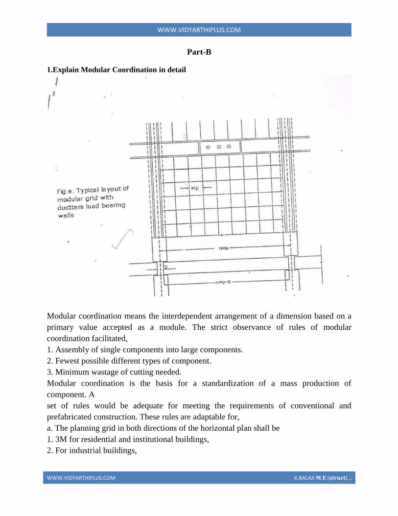
WWWVIDYARTHIPLUSCOM
WWWVIDYARTHIPLUSCOM KBALAJI 119820119812 (119852119853119851119854119836119853)
15M for spans up to 12m
30M for spans between 12m and 18m
60M for spans over 18m
The centre lines of load bearing walls shall coincide with the grid lines
b In case of external walls the grid lines shall coincide with the centre line of the wall or
a line on the wall 5 cm from the internal face of the wall
C The planning module in the vertical direction shall be 1M up to and including a ht of
28M
d Preferred increments for the still heights doors windows and other fenestration shall
be
1M
e In case of internal columns the grid lines shall coincide with the centre lines of
columns In case of external columns the grid lines shall coincide with the centre lines of
the columns in the storey or a line in the column from the internal face of the column in
the topmost storey A basic module can be represented as module and for larger project
modules are represented a Mp
For eg For a project module in horizontal coordination the component can be of 30cm
and for vertical component size be of 10cm
The storey height is fixed between finished floor levels as 28m and if the thickness of
slab is lt15cm storey height is fixed as 27m The centre distance between the load
bearing walls can be chose from a set of modules The use of other dimensions is not
allowed
In the design of a building modular grid can be used consisting of parallel line spaced at
a value of module M or Mp and a grid line chosen as a base for setting out a part of a
building becomes a modular axis In the fig (a) a typical grid is chosen for load bearing
walls without duct The interior walls are placed so that their centre lines coincide with
the modular axis In the fig (b) a grid is shown for load bearing walls with hollow ducts
in between The centre line of the grid is found by deducting the size of duct
WWWVIDYARTHIPLUSCOM
WWWVIDYARTHIPLUSCOM KBALAJI 119820119812 (119852119853119851119854119836119853)
2Systems of prefabrication
System is referred to a particular method of construction of buildings using the
prefabricated components which are inter related in functions and are produced to a set of
instructions With certain constraints several plans are possible using the same set of
components the degree of flexibility varies from system to system However in all the
systems there is a certain order and discipline The system of prefabricated construction
depends on the extend of the use of prefab components their characteristics to be
considered in devising a system
i Intensified usage of spaces
ii Straight and simple walling scheme
iii Limited sizes and numbers of components
iv Limited opening in bearing walls
v Regulated locations of partitions
vi Standardized service and stair units
vii Limited sizes of doors and windows with regulated positions
viii Structural clarity and efficiency
ix Suitability for adoption in low rise and high rise blocks
x Ease of manufacturing storing and transporting
xi Speed and ease of erection
xii Simple jointing system
a) Based on Disuniting of member
b) Based on the construction
WWWVIDYARTHIPLUSCOM
WWWVIDYARTHIPLUSCOM KBALAJI 119820119812 (119852119853119851119854119836119853)
Based on Disuniting of member
1 System consisting of linear member disunited at joints
2 System for prefabricates of entire rigid frame
3 System consisting of ITU of straight members disunited at points of minimum
moment
4 Two hinged and three hinged arches
System consisting of linear member disunited at joints
Advantage
Disuniting at joints gives linear member This means that a great advantage and facilitates
from the view point manufacture and assembly
Disadvantage
1 Joints are at corners ie at points of maximum moment values so forming the joint is
difficult
2 Joints must be over dimensioned to cope with in-situ concreting And one alternate
solution to replace moment resistant joints by hinged connection
System for prefabricates of entire rigid frame
WWWVIDYARTHIPLUSCOM
WWWVIDYARTHIPLUSCOM KBALAJI 119820119812 (119852119853119851119854119836119853)
In this system to reduce the no of joints and to precast larger numbers I one piece leads
to the prefabrication of entire frame Production of the frames does not cause any
particular trouble but the hoisting is more difficult and requires careful preparation The
stress distribution of straight members during hoisting is in general statistically
determinate
Advantage
1 It is ideal for site prefabrication
2 Small number of joints so rapid prefabrication work is possible
3 Suitable for long walls consisting of great number of uniform frames
System consisting of ITU of straight members disunited at points of minimum
moment
WWWVIDYARTHIPLUSCOM
WWWVIDYARTHIPLUSCOM KBALAJI 119820119812 (119852119853119851119854119836119853)
WWWVIDYARTHIPLUSCOM
WWWVIDYARTHIPLUSCOM KBALAJI 119820119812 (119852119853119851119854119836119853)
Another method of disuniting of structures is by division into different membranes at
points where the moments are thin or smallest This method is called as lambda method
Using this method hinge joints are made
Advantage
1 Functions are made at points of minimum moments or at points of contra flexure
2 Disuniting the main girder in this manner makes the application of different skylights
possible
Disadvantage
1 Hosting and temperature bracing of L joined asymmetric frame members is
WWWVIDYARTHIPLUSCOM
WWWVIDYARTHIPLUSCOM KBALAJI 119820119812 (119852119853119851119854119836119853)
particularly complicated
2 Temperature resting of frame member on each other necessitates the use of
cantilevers having half depth and proper forming of this cause difficulty
Two hinged and three hinged arches
Arched structures are normally two hinged and three hinged arches Arched structures are
normally used for bridging span more than 20-25m Their production and placing is more
difficult than straight members Arch can be two hinged and three hinged but they can
also be fixed at footings and can be constructed with or without tie
These members are generally precast and assembled in statistically determinant three
hinged variance and middle hinge is only eliminated after placing is finished The
reinforcing bars protruding both sides are welded together and the joint between the
members is filled in with insitu concrete
Arch structure can be precast in either vertical or horizontal positions In the first case
shuttering made of timber or concrete is required having the same curvature s the arch
itself
The prefabrication of larger arches in the horizontal position is found to be more
economical
The construction of arch trusses can be properly carried out in the horizontal position
only
WWWVIDYARTHIPLUSCOM
WWWVIDYARTHIPLUSCOM KBALAJI 119820119812 (119852119853119851119854119836119853)
3Methods of prefabrication
Site prefabrication- for large prefabricates
Plant prefabrication- large scale production
Site prefabrication
1 The RC members are produced t the site in the open air chiefly in the open air or in
the temporary sheds
2 The difficulties in construction in general are felt in this mechanization can case
3 Mechanization cannot be of such high degree as site PF is done for smaller duration
of time
4 When the pre fabricates are of large size it is difficult to transport the pre fabricates to
the site
5 In comparison with plant prefabrication transportation of the members are not needed
As large members are not transported the design and weight of the prefabricates are not
limited
Plant prefabrication
1 The members produced are to be transported t the place of construction this accounts
for about 10-15 of the cost of production and assembling
2 Certain restriction is made in the dimension of prefabrication leading to restraints in
the design and development of prefabrication
3 Prefabrication is appropriate for mass production for manufacture of standardized
members
4 Needs costly materials for batching and production
5 This method is most suited in the case of small prefabricates which are to be
prefabricated in very large number
Plant prefabrication is done under permanent plant or factories It is done under the
covered roof so the effect of weather does not affect the work So the quality and strength
of the members can be improved considerably Plant prefabrication reduces the cost of
prefabrication if the number of prefabricate needed is more
Dimensions of prefabricate
There are 3 commonly known dimension for the prefabricates
1 The design of the erection dimension governing the dimensional coordination of the
prefabricates
2 Theoretical dimension
3 The actual dimension of the element when delivered the design dimension should be a
multiple of a basic module size m or of a module lap
WWWVIDYARTHIPLUSCOM
WWWVIDYARTHIPLUSCOM KBALAJI 119820119812 (119852119853119851119854119836119853)
Production of prefabricates
Production techniques involved are
1 Stand method
2 Conveyor method or line method
3 Aggregate method
Stand Method
In this method the prefabrication mature where they are moulded while the production
teams moves to successive stands The bed on which prefabricates are cast may be fixed
or
movable Tilting forms are often used and in this method steam curing is generally done
Conveyor belt method
The whole production is split up in to series operations carried out at separate successive
and permanent points served by specialized teams The movement of the mould or
prefabricate one point to other vary by means of conveyor belt trolleys
The rigid steel forms are assembled at station 1 where they are mould oil to reduce the
adhesion of concrete The conveyor moves front 1 to 2 where prestressing wires are fixed
amp in the next station anchoring of the wires is carried out The prepared mould is then
carried to the station 1ie casting station After casting it is shifted to the vibrating table amp
finally stacked station 5 for setting After that it is passed through tunnel autoclave for
curing After steam curing move too station 7 for demoulding amp is finally stacked 8
Aggregate method
In the aggregate method aggregate describes large complex permanently installed
machines amp mechanical appliances which carry out most of the separate operations
involved in the casting of the concrete composition The stand is operated by a permanent
team amp the only move the prefabricate makes is to the maturing point
Aggregate method is used in the production of multi duct hollow floor panel in Poland
At production point the reinforcement is fixed in the form amp remote controlled
aggregate(machine)inserts the duct formers castamp vibrates the concrete floats the top
of the floor The prepared prefabricate then move to the autoclave chamber in which
hardening of concrete is accelerate In many factories combined technology are employed
when complex prefabricate are required
Advantages
1The stand technique is the most flexible one It is used in varying degrees of
mechanization in all kinds of prefabricate factories
2It is simple amp less capital is required It can be used for field prefabricate also
WWWVIDYARTHIPLUSCOM
WWWVIDYARTHIPLUSCOM KBALAJI 119820119812 (119852119853119851119854119836119853)
3Aggregate method is used for large scale production in which case number of
machineries is required
4 Explain specific requirements in layout of of prefabricated plants
WWWVIDYARTHIPLUSCOM
WWWVIDYARTHIPLUSCOM KBALAJI 119820119812 (119852119853119851119854119836119853)
WWWVIDYARTHIPLUSCOM
WWWVIDYARTHIPLUSCOM KBALAJI 119820119812 (119852119853119851119854119836119853)
5 Explain with neat sketch of the types of shear wall
WWWVIDYARTHIPLUSCOM
WWWVIDYARTHIPLUSCOM KBALAJI 119820119812 (119852119853119851119854119836119853)
WWWVIDYARTHIPLUSCOM
WWWVIDYARTHIPLUSCOM KBALAJI 119820119812 (119852119853119851119854119836119853)
6 What is the code use for prefabricated structures
WWWVIDYARTHIPLUSCOM
WWWVIDYARTHIPLUSCOM KBALAJI 119820119812 (119852119853119851119854119836119853)
7 Explain in detail various design consideration in the design of precast construction
WWWVIDYARTHIPLUSCOM
WWWVIDYARTHIPLUSCOM KBALAJI 119820119812 (119852119853119851119854119836119853)
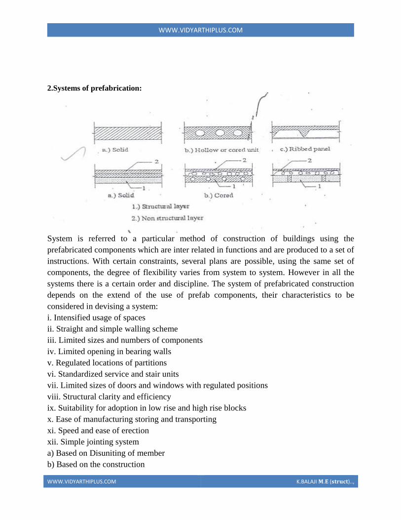
WWWVIDYARTHIPLUSCOM
WWWVIDYARTHIPLUSCOM KBALAJI 119820119812 (119852119853119851119854119836119853)
2Systems of prefabrication
System is referred to a particular method of construction of buildings using the
prefabricated components which are inter related in functions and are produced to a set of
instructions With certain constraints several plans are possible using the same set of
components the degree of flexibility varies from system to system However in all the
systems there is a certain order and discipline The system of prefabricated construction
depends on the extend of the use of prefab components their characteristics to be
considered in devising a system
i Intensified usage of spaces
ii Straight and simple walling scheme
iii Limited sizes and numbers of components
iv Limited opening in bearing walls
v Regulated locations of partitions
vi Standardized service and stair units
vii Limited sizes of doors and windows with regulated positions
viii Structural clarity and efficiency
ix Suitability for adoption in low rise and high rise blocks
x Ease of manufacturing storing and transporting
xi Speed and ease of erection
xii Simple jointing system
a) Based on Disuniting of member
b) Based on the construction
WWWVIDYARTHIPLUSCOM
WWWVIDYARTHIPLUSCOM KBALAJI 119820119812 (119852119853119851119854119836119853)
Based on Disuniting of member
1 System consisting of linear member disunited at joints
2 System for prefabricates of entire rigid frame
3 System consisting of ITU of straight members disunited at points of minimum
moment
4 Two hinged and three hinged arches
System consisting of linear member disunited at joints
Advantage
Disuniting at joints gives linear member This means that a great advantage and facilitates
from the view point manufacture and assembly
Disadvantage
1 Joints are at corners ie at points of maximum moment values so forming the joint is
difficult
2 Joints must be over dimensioned to cope with in-situ concreting And one alternate
solution to replace moment resistant joints by hinged connection
System for prefabricates of entire rigid frame
WWWVIDYARTHIPLUSCOM
WWWVIDYARTHIPLUSCOM KBALAJI 119820119812 (119852119853119851119854119836119853)
In this system to reduce the no of joints and to precast larger numbers I one piece leads
to the prefabrication of entire frame Production of the frames does not cause any
particular trouble but the hoisting is more difficult and requires careful preparation The
stress distribution of straight members during hoisting is in general statistically
determinate
Advantage
1 It is ideal for site prefabrication
2 Small number of joints so rapid prefabrication work is possible
3 Suitable for long walls consisting of great number of uniform frames
System consisting of ITU of straight members disunited at points of minimum
moment
WWWVIDYARTHIPLUSCOM
WWWVIDYARTHIPLUSCOM KBALAJI 119820119812 (119852119853119851119854119836119853)
WWWVIDYARTHIPLUSCOM
WWWVIDYARTHIPLUSCOM KBALAJI 119820119812 (119852119853119851119854119836119853)
Another method of disuniting of structures is by division into different membranes at
points where the moments are thin or smallest This method is called as lambda method
Using this method hinge joints are made
Advantage
1 Functions are made at points of minimum moments or at points of contra flexure
2 Disuniting the main girder in this manner makes the application of different skylights
possible
Disadvantage
1 Hosting and temperature bracing of L joined asymmetric frame members is
WWWVIDYARTHIPLUSCOM
WWWVIDYARTHIPLUSCOM KBALAJI 119820119812 (119852119853119851119854119836119853)
particularly complicated
2 Temperature resting of frame member on each other necessitates the use of
cantilevers having half depth and proper forming of this cause difficulty
Two hinged and three hinged arches
Arched structures are normally two hinged and three hinged arches Arched structures are
normally used for bridging span more than 20-25m Their production and placing is more
difficult than straight members Arch can be two hinged and three hinged but they can
also be fixed at footings and can be constructed with or without tie
These members are generally precast and assembled in statistically determinant three
hinged variance and middle hinge is only eliminated after placing is finished The
reinforcing bars protruding both sides are welded together and the joint between the
members is filled in with insitu concrete
Arch structure can be precast in either vertical or horizontal positions In the first case
shuttering made of timber or concrete is required having the same curvature s the arch
itself
The prefabrication of larger arches in the horizontal position is found to be more
economical
The construction of arch trusses can be properly carried out in the horizontal position
only
WWWVIDYARTHIPLUSCOM
WWWVIDYARTHIPLUSCOM KBALAJI 119820119812 (119852119853119851119854119836119853)
3Methods of prefabrication
Site prefabrication- for large prefabricates
Plant prefabrication- large scale production
Site prefabrication
1 The RC members are produced t the site in the open air chiefly in the open air or in
the temporary sheds
2 The difficulties in construction in general are felt in this mechanization can case
3 Mechanization cannot be of such high degree as site PF is done for smaller duration
of time
4 When the pre fabricates are of large size it is difficult to transport the pre fabricates to
the site
5 In comparison with plant prefabrication transportation of the members are not needed
As large members are not transported the design and weight of the prefabricates are not
limited
Plant prefabrication
1 The members produced are to be transported t the place of construction this accounts
for about 10-15 of the cost of production and assembling
2 Certain restriction is made in the dimension of prefabrication leading to restraints in
the design and development of prefabrication
3 Prefabrication is appropriate for mass production for manufacture of standardized
members
4 Needs costly materials for batching and production
5 This method is most suited in the case of small prefabricates which are to be
prefabricated in very large number
Plant prefabrication is done under permanent plant or factories It is done under the
covered roof so the effect of weather does not affect the work So the quality and strength
of the members can be improved considerably Plant prefabrication reduces the cost of
prefabrication if the number of prefabricate needed is more
Dimensions of prefabricate
There are 3 commonly known dimension for the prefabricates
1 The design of the erection dimension governing the dimensional coordination of the
prefabricates
2 Theoretical dimension
3 The actual dimension of the element when delivered the design dimension should be a
multiple of a basic module size m or of a module lap
WWWVIDYARTHIPLUSCOM
WWWVIDYARTHIPLUSCOM KBALAJI 119820119812 (119852119853119851119854119836119853)
Production of prefabricates
Production techniques involved are
1 Stand method
2 Conveyor method or line method
3 Aggregate method
Stand Method
In this method the prefabrication mature where they are moulded while the production
teams moves to successive stands The bed on which prefabricates are cast may be fixed
or
movable Tilting forms are often used and in this method steam curing is generally done
Conveyor belt method
The whole production is split up in to series operations carried out at separate successive
and permanent points served by specialized teams The movement of the mould or
prefabricate one point to other vary by means of conveyor belt trolleys
The rigid steel forms are assembled at station 1 where they are mould oil to reduce the
adhesion of concrete The conveyor moves front 1 to 2 where prestressing wires are fixed
amp in the next station anchoring of the wires is carried out The prepared mould is then
carried to the station 1ie casting station After casting it is shifted to the vibrating table amp
finally stacked station 5 for setting After that it is passed through tunnel autoclave for
curing After steam curing move too station 7 for demoulding amp is finally stacked 8
Aggregate method
In the aggregate method aggregate describes large complex permanently installed
machines amp mechanical appliances which carry out most of the separate operations
involved in the casting of the concrete composition The stand is operated by a permanent
team amp the only move the prefabricate makes is to the maturing point
Aggregate method is used in the production of multi duct hollow floor panel in Poland
At production point the reinforcement is fixed in the form amp remote controlled
aggregate(machine)inserts the duct formers castamp vibrates the concrete floats the top
of the floor The prepared prefabricate then move to the autoclave chamber in which
hardening of concrete is accelerate In many factories combined technology are employed
when complex prefabricate are required
Advantages
1The stand technique is the most flexible one It is used in varying degrees of
mechanization in all kinds of prefabricate factories
2It is simple amp less capital is required It can be used for field prefabricate also
WWWVIDYARTHIPLUSCOM
WWWVIDYARTHIPLUSCOM KBALAJI 119820119812 (119852119853119851119854119836119853)
3Aggregate method is used for large scale production in which case number of
machineries is required
4 Explain specific requirements in layout of of prefabricated plants
WWWVIDYARTHIPLUSCOM
WWWVIDYARTHIPLUSCOM KBALAJI 119820119812 (119852119853119851119854119836119853)
WWWVIDYARTHIPLUSCOM
WWWVIDYARTHIPLUSCOM KBALAJI 119820119812 (119852119853119851119854119836119853)
5 Explain with neat sketch of the types of shear wall
WWWVIDYARTHIPLUSCOM
WWWVIDYARTHIPLUSCOM KBALAJI 119820119812 (119852119853119851119854119836119853)
WWWVIDYARTHIPLUSCOM
WWWVIDYARTHIPLUSCOM KBALAJI 119820119812 (119852119853119851119854119836119853)
6 What is the code use for prefabricated structures
WWWVIDYARTHIPLUSCOM
WWWVIDYARTHIPLUSCOM KBALAJI 119820119812 (119852119853119851119854119836119853)
7 Explain in detail various design consideration in the design of precast construction
WWWVIDYARTHIPLUSCOM
WWWVIDYARTHIPLUSCOM KBALAJI 119820119812 (119852119853119851119854119836119853)
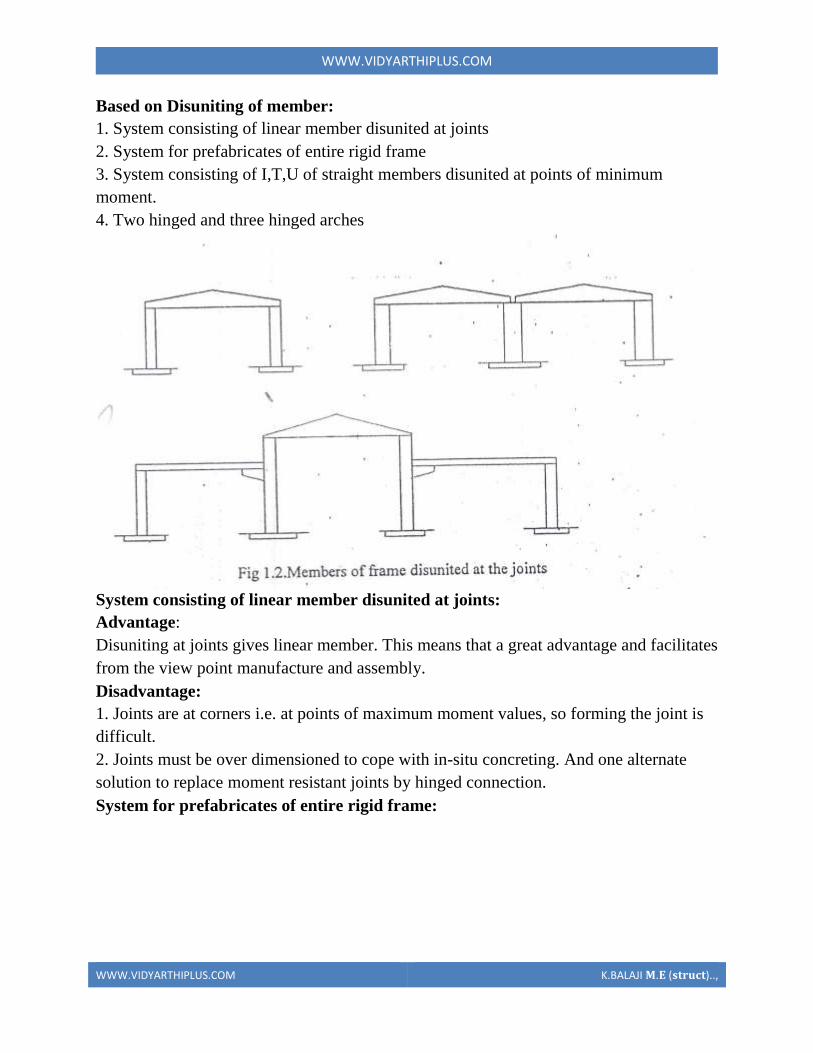
WWWVIDYARTHIPLUSCOM
WWWVIDYARTHIPLUSCOM KBALAJI 119820119812 (119852119853119851119854119836119853)
Based on Disuniting of member
1 System consisting of linear member disunited at joints
2 System for prefabricates of entire rigid frame
3 System consisting of ITU of straight members disunited at points of minimum
moment
4 Two hinged and three hinged arches
System consisting of linear member disunited at joints
Advantage
Disuniting at joints gives linear member This means that a great advantage and facilitates
from the view point manufacture and assembly
Disadvantage
1 Joints are at corners ie at points of maximum moment values so forming the joint is
difficult
2 Joints must be over dimensioned to cope with in-situ concreting And one alternate
solution to replace moment resistant joints by hinged connection
System for prefabricates of entire rigid frame
WWWVIDYARTHIPLUSCOM
WWWVIDYARTHIPLUSCOM KBALAJI 119820119812 (119852119853119851119854119836119853)
In this system to reduce the no of joints and to precast larger numbers I one piece leads
to the prefabrication of entire frame Production of the frames does not cause any
particular trouble but the hoisting is more difficult and requires careful preparation The
stress distribution of straight members during hoisting is in general statistically
determinate
Advantage
1 It is ideal for site prefabrication
2 Small number of joints so rapid prefabrication work is possible
3 Suitable for long walls consisting of great number of uniform frames
System consisting of ITU of straight members disunited at points of minimum
moment
WWWVIDYARTHIPLUSCOM
WWWVIDYARTHIPLUSCOM KBALAJI 119820119812 (119852119853119851119854119836119853)
WWWVIDYARTHIPLUSCOM
WWWVIDYARTHIPLUSCOM KBALAJI 119820119812 (119852119853119851119854119836119853)
Another method of disuniting of structures is by division into different membranes at
points where the moments are thin or smallest This method is called as lambda method
Using this method hinge joints are made
Advantage
1 Functions are made at points of minimum moments or at points of contra flexure
2 Disuniting the main girder in this manner makes the application of different skylights
possible
Disadvantage
1 Hosting and temperature bracing of L joined asymmetric frame members is
WWWVIDYARTHIPLUSCOM
WWWVIDYARTHIPLUSCOM KBALAJI 119820119812 (119852119853119851119854119836119853)
particularly complicated
2 Temperature resting of frame member on each other necessitates the use of
cantilevers having half depth and proper forming of this cause difficulty
Two hinged and three hinged arches
Arched structures are normally two hinged and three hinged arches Arched structures are
normally used for bridging span more than 20-25m Their production and placing is more
difficult than straight members Arch can be two hinged and three hinged but they can
also be fixed at footings and can be constructed with or without tie
These members are generally precast and assembled in statistically determinant three
hinged variance and middle hinge is only eliminated after placing is finished The
reinforcing bars protruding both sides are welded together and the joint between the
members is filled in with insitu concrete
Arch structure can be precast in either vertical or horizontal positions In the first case
shuttering made of timber or concrete is required having the same curvature s the arch
itself
The prefabrication of larger arches in the horizontal position is found to be more
economical
The construction of arch trusses can be properly carried out in the horizontal position
only
WWWVIDYARTHIPLUSCOM
WWWVIDYARTHIPLUSCOM KBALAJI 119820119812 (119852119853119851119854119836119853)
3Methods of prefabrication
Site prefabrication- for large prefabricates
Plant prefabrication- large scale production
Site prefabrication
1 The RC members are produced t the site in the open air chiefly in the open air or in
the temporary sheds
2 The difficulties in construction in general are felt in this mechanization can case
3 Mechanization cannot be of such high degree as site PF is done for smaller duration
of time
4 When the pre fabricates are of large size it is difficult to transport the pre fabricates to
the site
5 In comparison with plant prefabrication transportation of the members are not needed
As large members are not transported the design and weight of the prefabricates are not
limited
Plant prefabrication
1 The members produced are to be transported t the place of construction this accounts
for about 10-15 of the cost of production and assembling
2 Certain restriction is made in the dimension of prefabrication leading to restraints in
the design and development of prefabrication
3 Prefabrication is appropriate for mass production for manufacture of standardized
members
4 Needs costly materials for batching and production
5 This method is most suited in the case of small prefabricates which are to be
prefabricated in very large number
Plant prefabrication is done under permanent plant or factories It is done under the
covered roof so the effect of weather does not affect the work So the quality and strength
of the members can be improved considerably Plant prefabrication reduces the cost of
prefabrication if the number of prefabricate needed is more
Dimensions of prefabricate
There are 3 commonly known dimension for the prefabricates
1 The design of the erection dimension governing the dimensional coordination of the
prefabricates
2 Theoretical dimension
3 The actual dimension of the element when delivered the design dimension should be a
multiple of a basic module size m or of a module lap
WWWVIDYARTHIPLUSCOM
WWWVIDYARTHIPLUSCOM KBALAJI 119820119812 (119852119853119851119854119836119853)
Production of prefabricates
Production techniques involved are
1 Stand method
2 Conveyor method or line method
3 Aggregate method
Stand Method
In this method the prefabrication mature where they are moulded while the production
teams moves to successive stands The bed on which prefabricates are cast may be fixed
or
movable Tilting forms are often used and in this method steam curing is generally done
Conveyor belt method
The whole production is split up in to series operations carried out at separate successive
and permanent points served by specialized teams The movement of the mould or
prefabricate one point to other vary by means of conveyor belt trolleys
The rigid steel forms are assembled at station 1 where they are mould oil to reduce the
adhesion of concrete The conveyor moves front 1 to 2 where prestressing wires are fixed
amp in the next station anchoring of the wires is carried out The prepared mould is then
carried to the station 1ie casting station After casting it is shifted to the vibrating table amp
finally stacked station 5 for setting After that it is passed through tunnel autoclave for
curing After steam curing move too station 7 for demoulding amp is finally stacked 8
Aggregate method
In the aggregate method aggregate describes large complex permanently installed
machines amp mechanical appliances which carry out most of the separate operations
involved in the casting of the concrete composition The stand is operated by a permanent
team amp the only move the prefabricate makes is to the maturing point
Aggregate method is used in the production of multi duct hollow floor panel in Poland
At production point the reinforcement is fixed in the form amp remote controlled
aggregate(machine)inserts the duct formers castamp vibrates the concrete floats the top
of the floor The prepared prefabricate then move to the autoclave chamber in which
hardening of concrete is accelerate In many factories combined technology are employed
when complex prefabricate are required
Advantages
1The stand technique is the most flexible one It is used in varying degrees of
mechanization in all kinds of prefabricate factories
2It is simple amp less capital is required It can be used for field prefabricate also
WWWVIDYARTHIPLUSCOM
WWWVIDYARTHIPLUSCOM KBALAJI 119820119812 (119852119853119851119854119836119853)
3Aggregate method is used for large scale production in which case number of
machineries is required
4 Explain specific requirements in layout of of prefabricated plants
WWWVIDYARTHIPLUSCOM
WWWVIDYARTHIPLUSCOM KBALAJI 119820119812 (119852119853119851119854119836119853)
WWWVIDYARTHIPLUSCOM
WWWVIDYARTHIPLUSCOM KBALAJI 119820119812 (119852119853119851119854119836119853)
5 Explain with neat sketch of the types of shear wall
WWWVIDYARTHIPLUSCOM
WWWVIDYARTHIPLUSCOM KBALAJI 119820119812 (119852119853119851119854119836119853)
WWWVIDYARTHIPLUSCOM
WWWVIDYARTHIPLUSCOM KBALAJI 119820119812 (119852119853119851119854119836119853)
6 What is the code use for prefabricated structures
WWWVIDYARTHIPLUSCOM
WWWVIDYARTHIPLUSCOM KBALAJI 119820119812 (119852119853119851119854119836119853)
7 Explain in detail various design consideration in the design of precast construction
WWWVIDYARTHIPLUSCOM
WWWVIDYARTHIPLUSCOM KBALAJI 119820119812 (119852119853119851119854119836119853)
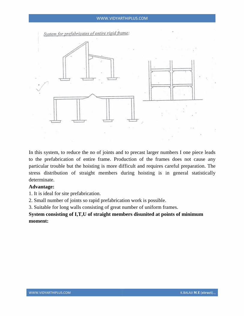
WWWVIDYARTHIPLUSCOM
WWWVIDYARTHIPLUSCOM KBALAJI 119820119812 (119852119853119851119854119836119853)
In this system to reduce the no of joints and to precast larger numbers I one piece leads
to the prefabrication of entire frame Production of the frames does not cause any
particular trouble but the hoisting is more difficult and requires careful preparation The
stress distribution of straight members during hoisting is in general statistically
determinate
Advantage
1 It is ideal for site prefabrication
2 Small number of joints so rapid prefabrication work is possible
3 Suitable for long walls consisting of great number of uniform frames
System consisting of ITU of straight members disunited at points of minimum
moment
WWWVIDYARTHIPLUSCOM
WWWVIDYARTHIPLUSCOM KBALAJI 119820119812 (119852119853119851119854119836119853)
WWWVIDYARTHIPLUSCOM
WWWVIDYARTHIPLUSCOM KBALAJI 119820119812 (119852119853119851119854119836119853)
Another method of disuniting of structures is by division into different membranes at
points where the moments are thin or smallest This method is called as lambda method
Using this method hinge joints are made
Advantage
1 Functions are made at points of minimum moments or at points of contra flexure
2 Disuniting the main girder in this manner makes the application of different skylights
possible
Disadvantage
1 Hosting and temperature bracing of L joined asymmetric frame members is
WWWVIDYARTHIPLUSCOM
WWWVIDYARTHIPLUSCOM KBALAJI 119820119812 (119852119853119851119854119836119853)
particularly complicated
2 Temperature resting of frame member on each other necessitates the use of
cantilevers having half depth and proper forming of this cause difficulty
Two hinged and three hinged arches
Arched structures are normally two hinged and three hinged arches Arched structures are
normally used for bridging span more than 20-25m Their production and placing is more
difficult than straight members Arch can be two hinged and three hinged but they can
also be fixed at footings and can be constructed with or without tie
These members are generally precast and assembled in statistically determinant three
hinged variance and middle hinge is only eliminated after placing is finished The
reinforcing bars protruding both sides are welded together and the joint between the
members is filled in with insitu concrete
Arch structure can be precast in either vertical or horizontal positions In the first case
shuttering made of timber or concrete is required having the same curvature s the arch
itself
The prefabrication of larger arches in the horizontal position is found to be more
economical
The construction of arch trusses can be properly carried out in the horizontal position
only
WWWVIDYARTHIPLUSCOM
WWWVIDYARTHIPLUSCOM KBALAJI 119820119812 (119852119853119851119854119836119853)
3Methods of prefabrication
Site prefabrication- for large prefabricates
Plant prefabrication- large scale production
Site prefabrication
1 The RC members are produced t the site in the open air chiefly in the open air or in
the temporary sheds
2 The difficulties in construction in general are felt in this mechanization can case
3 Mechanization cannot be of such high degree as site PF is done for smaller duration
of time
4 When the pre fabricates are of large size it is difficult to transport the pre fabricates to
the site
5 In comparison with plant prefabrication transportation of the members are not needed
As large members are not transported the design and weight of the prefabricates are not
limited
Plant prefabrication
1 The members produced are to be transported t the place of construction this accounts
for about 10-15 of the cost of production and assembling
2 Certain restriction is made in the dimension of prefabrication leading to restraints in
the design and development of prefabrication
3 Prefabrication is appropriate for mass production for manufacture of standardized
members
4 Needs costly materials for batching and production
5 This method is most suited in the case of small prefabricates which are to be
prefabricated in very large number
Plant prefabrication is done under permanent plant or factories It is done under the
covered roof so the effect of weather does not affect the work So the quality and strength
of the members can be improved considerably Plant prefabrication reduces the cost of
prefabrication if the number of prefabricate needed is more
Dimensions of prefabricate
There are 3 commonly known dimension for the prefabricates
1 The design of the erection dimension governing the dimensional coordination of the
prefabricates
2 Theoretical dimension
3 The actual dimension of the element when delivered the design dimension should be a
multiple of a basic module size m or of a module lap
WWWVIDYARTHIPLUSCOM
WWWVIDYARTHIPLUSCOM KBALAJI 119820119812 (119852119853119851119854119836119853)
Production of prefabricates
Production techniques involved are
1 Stand method
2 Conveyor method or line method
3 Aggregate method
Stand Method
In this method the prefabrication mature where they are moulded while the production
teams moves to successive stands The bed on which prefabricates are cast may be fixed
or
movable Tilting forms are often used and in this method steam curing is generally done
Conveyor belt method
The whole production is split up in to series operations carried out at separate successive
and permanent points served by specialized teams The movement of the mould or
prefabricate one point to other vary by means of conveyor belt trolleys
The rigid steel forms are assembled at station 1 where they are mould oil to reduce the
adhesion of concrete The conveyor moves front 1 to 2 where prestressing wires are fixed
amp in the next station anchoring of the wires is carried out The prepared mould is then
carried to the station 1ie casting station After casting it is shifted to the vibrating table amp
finally stacked station 5 for setting After that it is passed through tunnel autoclave for
curing After steam curing move too station 7 for demoulding amp is finally stacked 8
Aggregate method
In the aggregate method aggregate describes large complex permanently installed
machines amp mechanical appliances which carry out most of the separate operations
involved in the casting of the concrete composition The stand is operated by a permanent
team amp the only move the prefabricate makes is to the maturing point
Aggregate method is used in the production of multi duct hollow floor panel in Poland
At production point the reinforcement is fixed in the form amp remote controlled
aggregate(machine)inserts the duct formers castamp vibrates the concrete floats the top
of the floor The prepared prefabricate then move to the autoclave chamber in which
hardening of concrete is accelerate In many factories combined technology are employed
when complex prefabricate are required
Advantages
1The stand technique is the most flexible one It is used in varying degrees of
mechanization in all kinds of prefabricate factories
2It is simple amp less capital is required It can be used for field prefabricate also
WWWVIDYARTHIPLUSCOM
WWWVIDYARTHIPLUSCOM KBALAJI 119820119812 (119852119853119851119854119836119853)
3Aggregate method is used for large scale production in which case number of
machineries is required
4 Explain specific requirements in layout of of prefabricated plants
WWWVIDYARTHIPLUSCOM
WWWVIDYARTHIPLUSCOM KBALAJI 119820119812 (119852119853119851119854119836119853)
WWWVIDYARTHIPLUSCOM
WWWVIDYARTHIPLUSCOM KBALAJI 119820119812 (119852119853119851119854119836119853)
5 Explain with neat sketch of the types of shear wall
WWWVIDYARTHIPLUSCOM
WWWVIDYARTHIPLUSCOM KBALAJI 119820119812 (119852119853119851119854119836119853)
WWWVIDYARTHIPLUSCOM
WWWVIDYARTHIPLUSCOM KBALAJI 119820119812 (119852119853119851119854119836119853)
6 What is the code use for prefabricated structures
WWWVIDYARTHIPLUSCOM
WWWVIDYARTHIPLUSCOM KBALAJI 119820119812 (119852119853119851119854119836119853)
7 Explain in detail various design consideration in the design of precast construction
WWWVIDYARTHIPLUSCOM
WWWVIDYARTHIPLUSCOM KBALAJI 119820119812 (119852119853119851119854119836119853)
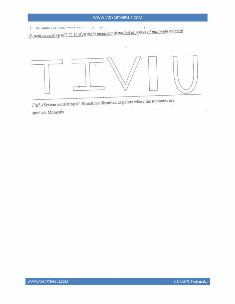
WWWVIDYARTHIPLUSCOM
WWWVIDYARTHIPLUSCOM KBALAJI 119820119812 (119852119853119851119854119836119853)
WWWVIDYARTHIPLUSCOM
WWWVIDYARTHIPLUSCOM KBALAJI 119820119812 (119852119853119851119854119836119853)
Another method of disuniting of structures is by division into different membranes at
points where the moments are thin or smallest This method is called as lambda method
Using this method hinge joints are made
Advantage
1 Functions are made at points of minimum moments or at points of contra flexure
2 Disuniting the main girder in this manner makes the application of different skylights
possible
Disadvantage
1 Hosting and temperature bracing of L joined asymmetric frame members is
WWWVIDYARTHIPLUSCOM
WWWVIDYARTHIPLUSCOM KBALAJI 119820119812 (119852119853119851119854119836119853)
particularly complicated
2 Temperature resting of frame member on each other necessitates the use of
cantilevers having half depth and proper forming of this cause difficulty
Two hinged and three hinged arches
Arched structures are normally two hinged and three hinged arches Arched structures are
normally used for bridging span more than 20-25m Their production and placing is more
difficult than straight members Arch can be two hinged and three hinged but they can
also be fixed at footings and can be constructed with or without tie
These members are generally precast and assembled in statistically determinant three
hinged variance and middle hinge is only eliminated after placing is finished The
reinforcing bars protruding both sides are welded together and the joint between the
members is filled in with insitu concrete
Arch structure can be precast in either vertical or horizontal positions In the first case
shuttering made of timber or concrete is required having the same curvature s the arch
itself
The prefabrication of larger arches in the horizontal position is found to be more
economical
The construction of arch trusses can be properly carried out in the horizontal position
only
WWWVIDYARTHIPLUSCOM
WWWVIDYARTHIPLUSCOM KBALAJI 119820119812 (119852119853119851119854119836119853)
3Methods of prefabrication
Site prefabrication- for large prefabricates
Plant prefabrication- large scale production
Site prefabrication
1 The RC members are produced t the site in the open air chiefly in the open air or in
the temporary sheds
2 The difficulties in construction in general are felt in this mechanization can case
3 Mechanization cannot be of such high degree as site PF is done for smaller duration
of time
4 When the pre fabricates are of large size it is difficult to transport the pre fabricates to
the site
5 In comparison with plant prefabrication transportation of the members are not needed
As large members are not transported the design and weight of the prefabricates are not
limited
Plant prefabrication
1 The members produced are to be transported t the place of construction this accounts
for about 10-15 of the cost of production and assembling
2 Certain restriction is made in the dimension of prefabrication leading to restraints in
the design and development of prefabrication
3 Prefabrication is appropriate for mass production for manufacture of standardized
members
4 Needs costly materials for batching and production
5 This method is most suited in the case of small prefabricates which are to be
prefabricated in very large number
Plant prefabrication is done under permanent plant or factories It is done under the
covered roof so the effect of weather does not affect the work So the quality and strength
of the members can be improved considerably Plant prefabrication reduces the cost of
prefabrication if the number of prefabricate needed is more
Dimensions of prefabricate
There are 3 commonly known dimension for the prefabricates
1 The design of the erection dimension governing the dimensional coordination of the
prefabricates
2 Theoretical dimension
3 The actual dimension of the element when delivered the design dimension should be a
multiple of a basic module size m or of a module lap
WWWVIDYARTHIPLUSCOM
WWWVIDYARTHIPLUSCOM KBALAJI 119820119812 (119852119853119851119854119836119853)
Production of prefabricates
Production techniques involved are
1 Stand method
2 Conveyor method or line method
3 Aggregate method
Stand Method
In this method the prefabrication mature where they are moulded while the production
teams moves to successive stands The bed on which prefabricates are cast may be fixed
or
movable Tilting forms are often used and in this method steam curing is generally done
Conveyor belt method
The whole production is split up in to series operations carried out at separate successive
and permanent points served by specialized teams The movement of the mould or
prefabricate one point to other vary by means of conveyor belt trolleys
The rigid steel forms are assembled at station 1 where they are mould oil to reduce the
adhesion of concrete The conveyor moves front 1 to 2 where prestressing wires are fixed
amp in the next station anchoring of the wires is carried out The prepared mould is then
carried to the station 1ie casting station After casting it is shifted to the vibrating table amp
finally stacked station 5 for setting After that it is passed through tunnel autoclave for
curing After steam curing move too station 7 for demoulding amp is finally stacked 8
Aggregate method
In the aggregate method aggregate describes large complex permanently installed
machines amp mechanical appliances which carry out most of the separate operations
involved in the casting of the concrete composition The stand is operated by a permanent
team amp the only move the prefabricate makes is to the maturing point
Aggregate method is used in the production of multi duct hollow floor panel in Poland
At production point the reinforcement is fixed in the form amp remote controlled
aggregate(machine)inserts the duct formers castamp vibrates the concrete floats the top
of the floor The prepared prefabricate then move to the autoclave chamber in which
hardening of concrete is accelerate In many factories combined technology are employed
when complex prefabricate are required
Advantages
1The stand technique is the most flexible one It is used in varying degrees of
mechanization in all kinds of prefabricate factories
2It is simple amp less capital is required It can be used for field prefabricate also
WWWVIDYARTHIPLUSCOM
WWWVIDYARTHIPLUSCOM KBALAJI 119820119812 (119852119853119851119854119836119853)
3Aggregate method is used for large scale production in which case number of
machineries is required
4 Explain specific requirements in layout of of prefabricated plants
WWWVIDYARTHIPLUSCOM
WWWVIDYARTHIPLUSCOM KBALAJI 119820119812 (119852119853119851119854119836119853)
WWWVIDYARTHIPLUSCOM
WWWVIDYARTHIPLUSCOM KBALAJI 119820119812 (119852119853119851119854119836119853)
5 Explain with neat sketch of the types of shear wall
WWWVIDYARTHIPLUSCOM
WWWVIDYARTHIPLUSCOM KBALAJI 119820119812 (119852119853119851119854119836119853)
WWWVIDYARTHIPLUSCOM
WWWVIDYARTHIPLUSCOM KBALAJI 119820119812 (119852119853119851119854119836119853)
6 What is the code use for prefabricated structures
WWWVIDYARTHIPLUSCOM
WWWVIDYARTHIPLUSCOM KBALAJI 119820119812 (119852119853119851119854119836119853)
7 Explain in detail various design consideration in the design of precast construction
WWWVIDYARTHIPLUSCOM
WWWVIDYARTHIPLUSCOM KBALAJI 119820119812 (119852119853119851119854119836119853)
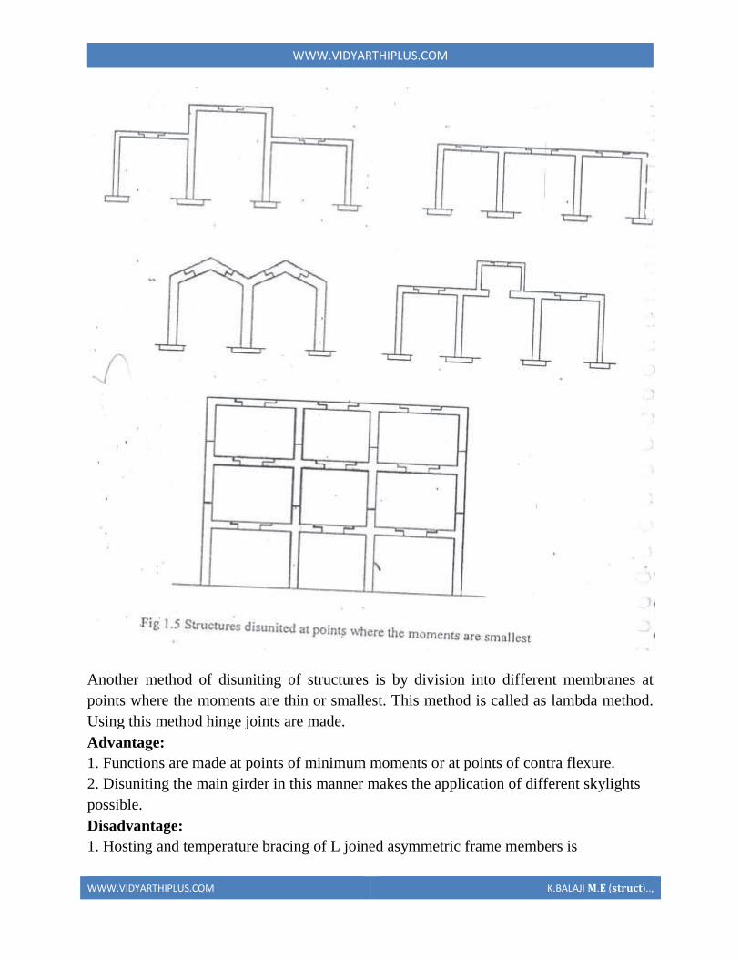
WWWVIDYARTHIPLUSCOM
WWWVIDYARTHIPLUSCOM KBALAJI 119820119812 (119852119853119851119854119836119853)
Another method of disuniting of structures is by division into different membranes at
points where the moments are thin or smallest This method is called as lambda method
Using this method hinge joints are made
Advantage
1 Functions are made at points of minimum moments or at points of contra flexure
2 Disuniting the main girder in this manner makes the application of different skylights
possible
Disadvantage
1 Hosting and temperature bracing of L joined asymmetric frame members is
WWWVIDYARTHIPLUSCOM
WWWVIDYARTHIPLUSCOM KBALAJI 119820119812 (119852119853119851119854119836119853)
particularly complicated
2 Temperature resting of frame member on each other necessitates the use of
cantilevers having half depth and proper forming of this cause difficulty
Two hinged and three hinged arches
Arched structures are normally two hinged and three hinged arches Arched structures are
normally used for bridging span more than 20-25m Their production and placing is more
difficult than straight members Arch can be two hinged and three hinged but they can
also be fixed at footings and can be constructed with or without tie
These members are generally precast and assembled in statistically determinant three
hinged variance and middle hinge is only eliminated after placing is finished The
reinforcing bars protruding both sides are welded together and the joint between the
members is filled in with insitu concrete
Arch structure can be precast in either vertical or horizontal positions In the first case
shuttering made of timber or concrete is required having the same curvature s the arch
itself
The prefabrication of larger arches in the horizontal position is found to be more
economical
The construction of arch trusses can be properly carried out in the horizontal position
only
WWWVIDYARTHIPLUSCOM
WWWVIDYARTHIPLUSCOM KBALAJI 119820119812 (119852119853119851119854119836119853)
3Methods of prefabrication
Site prefabrication- for large prefabricates
Plant prefabrication- large scale production
Site prefabrication
1 The RC members are produced t the site in the open air chiefly in the open air or in
the temporary sheds
2 The difficulties in construction in general are felt in this mechanization can case
3 Mechanization cannot be of such high degree as site PF is done for smaller duration
of time
4 When the pre fabricates are of large size it is difficult to transport the pre fabricates to
the site
5 In comparison with plant prefabrication transportation of the members are not needed
As large members are not transported the design and weight of the prefabricates are not
limited
Plant prefabrication
1 The members produced are to be transported t the place of construction this accounts
for about 10-15 of the cost of production and assembling
2 Certain restriction is made in the dimension of prefabrication leading to restraints in
the design and development of prefabrication
3 Prefabrication is appropriate for mass production for manufacture of standardized
members
4 Needs costly materials for batching and production
5 This method is most suited in the case of small prefabricates which are to be
prefabricated in very large number
Plant prefabrication is done under permanent plant or factories It is done under the
covered roof so the effect of weather does not affect the work So the quality and strength
of the members can be improved considerably Plant prefabrication reduces the cost of
prefabrication if the number of prefabricate needed is more
Dimensions of prefabricate
There are 3 commonly known dimension for the prefabricates
1 The design of the erection dimension governing the dimensional coordination of the
prefabricates
2 Theoretical dimension
3 The actual dimension of the element when delivered the design dimension should be a
multiple of a basic module size m or of a module lap
WWWVIDYARTHIPLUSCOM
WWWVIDYARTHIPLUSCOM KBALAJI 119820119812 (119852119853119851119854119836119853)
Production of prefabricates
Production techniques involved are
1 Stand method
2 Conveyor method or line method
3 Aggregate method
Stand Method
In this method the prefabrication mature where they are moulded while the production
teams moves to successive stands The bed on which prefabricates are cast may be fixed
or
movable Tilting forms are often used and in this method steam curing is generally done
Conveyor belt method
The whole production is split up in to series operations carried out at separate successive
and permanent points served by specialized teams The movement of the mould or
prefabricate one point to other vary by means of conveyor belt trolleys
The rigid steel forms are assembled at station 1 where they are mould oil to reduce the
adhesion of concrete The conveyor moves front 1 to 2 where prestressing wires are fixed
amp in the next station anchoring of the wires is carried out The prepared mould is then
carried to the station 1ie casting station After casting it is shifted to the vibrating table amp
finally stacked station 5 for setting After that it is passed through tunnel autoclave for
curing After steam curing move too station 7 for demoulding amp is finally stacked 8
Aggregate method
In the aggregate method aggregate describes large complex permanently installed
machines amp mechanical appliances which carry out most of the separate operations
involved in the casting of the concrete composition The stand is operated by a permanent
team amp the only move the prefabricate makes is to the maturing point
Aggregate method is used in the production of multi duct hollow floor panel in Poland
At production point the reinforcement is fixed in the form amp remote controlled
aggregate(machine)inserts the duct formers castamp vibrates the concrete floats the top
of the floor The prepared prefabricate then move to the autoclave chamber in which
hardening of concrete is accelerate In many factories combined technology are employed
when complex prefabricate are required
Advantages
1The stand technique is the most flexible one It is used in varying degrees of
mechanization in all kinds of prefabricate factories
2It is simple amp less capital is required It can be used for field prefabricate also
WWWVIDYARTHIPLUSCOM
WWWVIDYARTHIPLUSCOM KBALAJI 119820119812 (119852119853119851119854119836119853)
3Aggregate method is used for large scale production in which case number of
machineries is required
4 Explain specific requirements in layout of of prefabricated plants
WWWVIDYARTHIPLUSCOM
WWWVIDYARTHIPLUSCOM KBALAJI 119820119812 (119852119853119851119854119836119853)
WWWVIDYARTHIPLUSCOM
WWWVIDYARTHIPLUSCOM KBALAJI 119820119812 (119852119853119851119854119836119853)
5 Explain with neat sketch of the types of shear wall
WWWVIDYARTHIPLUSCOM
WWWVIDYARTHIPLUSCOM KBALAJI 119820119812 (119852119853119851119854119836119853)
WWWVIDYARTHIPLUSCOM
WWWVIDYARTHIPLUSCOM KBALAJI 119820119812 (119852119853119851119854119836119853)
6 What is the code use for prefabricated structures
WWWVIDYARTHIPLUSCOM
WWWVIDYARTHIPLUSCOM KBALAJI 119820119812 (119852119853119851119854119836119853)
7 Explain in detail various design consideration in the design of precast construction
WWWVIDYARTHIPLUSCOM
WWWVIDYARTHIPLUSCOM KBALAJI 119820119812 (119852119853119851119854119836119853)
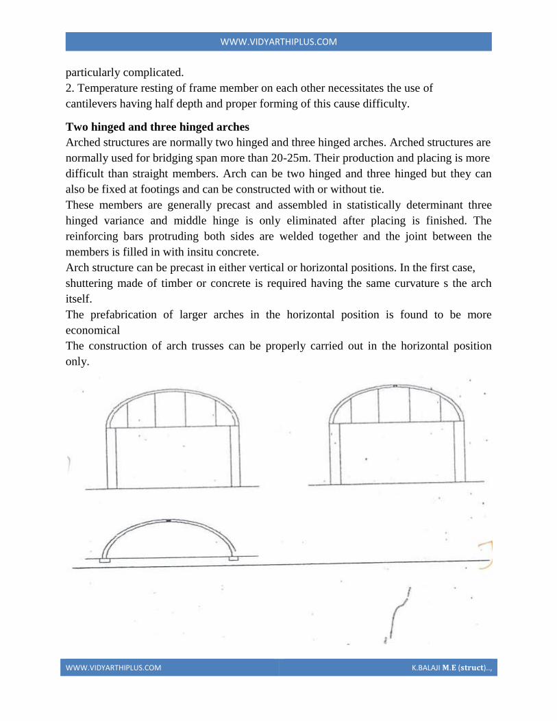
WWWVIDYARTHIPLUSCOM
WWWVIDYARTHIPLUSCOM KBALAJI 119820119812 (119852119853119851119854119836119853)
particularly complicated
2 Temperature resting of frame member on each other necessitates the use of
cantilevers having half depth and proper forming of this cause difficulty
Two hinged and three hinged arches
Arched structures are normally two hinged and three hinged arches Arched structures are
normally used for bridging span more than 20-25m Their production and placing is more
difficult than straight members Arch can be two hinged and three hinged but they can
also be fixed at footings and can be constructed with or without tie
These members are generally precast and assembled in statistically determinant three
hinged variance and middle hinge is only eliminated after placing is finished The
reinforcing bars protruding both sides are welded together and the joint between the
members is filled in with insitu concrete
Arch structure can be precast in either vertical or horizontal positions In the first case
shuttering made of timber or concrete is required having the same curvature s the arch
itself
The prefabrication of larger arches in the horizontal position is found to be more
economical
The construction of arch trusses can be properly carried out in the horizontal position
only
WWWVIDYARTHIPLUSCOM
WWWVIDYARTHIPLUSCOM KBALAJI 119820119812 (119852119853119851119854119836119853)
3Methods of prefabrication
Site prefabrication- for large prefabricates
Plant prefabrication- large scale production
Site prefabrication
1 The RC members are produced t the site in the open air chiefly in the open air or in
the temporary sheds
2 The difficulties in construction in general are felt in this mechanization can case
3 Mechanization cannot be of such high degree as site PF is done for smaller duration
of time
4 When the pre fabricates are of large size it is difficult to transport the pre fabricates to
the site
5 In comparison with plant prefabrication transportation of the members are not needed
As large members are not transported the design and weight of the prefabricates are not
limited
Plant prefabrication
1 The members produced are to be transported t the place of construction this accounts
for about 10-15 of the cost of production and assembling
2 Certain restriction is made in the dimension of prefabrication leading to restraints in
the design and development of prefabrication
3 Prefabrication is appropriate for mass production for manufacture of standardized
members
4 Needs costly materials for batching and production
5 This method is most suited in the case of small prefabricates which are to be
prefabricated in very large number
Plant prefabrication is done under permanent plant or factories It is done under the
covered roof so the effect of weather does not affect the work So the quality and strength
of the members can be improved considerably Plant prefabrication reduces the cost of
prefabrication if the number of prefabricate needed is more
Dimensions of prefabricate
There are 3 commonly known dimension for the prefabricates
1 The design of the erection dimension governing the dimensional coordination of the
prefabricates
2 Theoretical dimension
3 The actual dimension of the element when delivered the design dimension should be a
multiple of a basic module size m or of a module lap
WWWVIDYARTHIPLUSCOM
WWWVIDYARTHIPLUSCOM KBALAJI 119820119812 (119852119853119851119854119836119853)
Production of prefabricates
Production techniques involved are
1 Stand method
2 Conveyor method or line method
3 Aggregate method
Stand Method
In this method the prefabrication mature where they are moulded while the production
teams moves to successive stands The bed on which prefabricates are cast may be fixed
or
movable Tilting forms are often used and in this method steam curing is generally done
Conveyor belt method
The whole production is split up in to series operations carried out at separate successive
and permanent points served by specialized teams The movement of the mould or
prefabricate one point to other vary by means of conveyor belt trolleys
The rigid steel forms are assembled at station 1 where they are mould oil to reduce the
adhesion of concrete The conveyor moves front 1 to 2 where prestressing wires are fixed
amp in the next station anchoring of the wires is carried out The prepared mould is then
carried to the station 1ie casting station After casting it is shifted to the vibrating table amp
finally stacked station 5 for setting After that it is passed through tunnel autoclave for
curing After steam curing move too station 7 for demoulding amp is finally stacked 8
Aggregate method
In the aggregate method aggregate describes large complex permanently installed
machines amp mechanical appliances which carry out most of the separate operations
involved in the casting of the concrete composition The stand is operated by a permanent
team amp the only move the prefabricate makes is to the maturing point
Aggregate method is used in the production of multi duct hollow floor panel in Poland
At production point the reinforcement is fixed in the form amp remote controlled
aggregate(machine)inserts the duct formers castamp vibrates the concrete floats the top
of the floor The prepared prefabricate then move to the autoclave chamber in which
hardening of concrete is accelerate In many factories combined technology are employed
when complex prefabricate are required
Advantages
1The stand technique is the most flexible one It is used in varying degrees of
mechanization in all kinds of prefabricate factories
2It is simple amp less capital is required It can be used for field prefabricate also
WWWVIDYARTHIPLUSCOM
WWWVIDYARTHIPLUSCOM KBALAJI 119820119812 (119852119853119851119854119836119853)
3Aggregate method is used for large scale production in which case number of
machineries is required
4 Explain specific requirements in layout of of prefabricated plants
WWWVIDYARTHIPLUSCOM
WWWVIDYARTHIPLUSCOM KBALAJI 119820119812 (119852119853119851119854119836119853)
WWWVIDYARTHIPLUSCOM
WWWVIDYARTHIPLUSCOM KBALAJI 119820119812 (119852119853119851119854119836119853)
5 Explain with neat sketch of the types of shear wall
WWWVIDYARTHIPLUSCOM
WWWVIDYARTHIPLUSCOM KBALAJI 119820119812 (119852119853119851119854119836119853)
WWWVIDYARTHIPLUSCOM
WWWVIDYARTHIPLUSCOM KBALAJI 119820119812 (119852119853119851119854119836119853)
6 What is the code use for prefabricated structures
WWWVIDYARTHIPLUSCOM
WWWVIDYARTHIPLUSCOM KBALAJI 119820119812 (119852119853119851119854119836119853)
7 Explain in detail various design consideration in the design of precast construction
WWWVIDYARTHIPLUSCOM
WWWVIDYARTHIPLUSCOM KBALAJI 119820119812 (119852119853119851119854119836119853)
WWWVIDYARTHIPLUSCOM
WWWVIDYARTHIPLUSCOM KBALAJI 119820119812 (119852119853119851119854119836119853)
3Methods of prefabrication
Site prefabrication- for large prefabricates
Plant prefabrication- large scale production
Site prefabrication
1 The RC members are produced t the site in the open air chiefly in the open air or in
the temporary sheds
2 The difficulties in construction in general are felt in this mechanization can case
3 Mechanization cannot be of such high degree as site PF is done for smaller duration
of time
4 When the pre fabricates are of large size it is difficult to transport the pre fabricates to
the site
5 In comparison with plant prefabrication transportation of the members are not needed
As large members are not transported the design and weight of the prefabricates are not
limited
Plant prefabrication
1 The members produced are to be transported t the place of construction this accounts
for about 10-15 of the cost of production and assembling
2 Certain restriction is made in the dimension of prefabrication leading to restraints in
the design and development of prefabrication
3 Prefabrication is appropriate for mass production for manufacture of standardized
members
4 Needs costly materials for batching and production
5 This method is most suited in the case of small prefabricates which are to be
prefabricated in very large number
Plant prefabrication is done under permanent plant or factories It is done under the
covered roof so the effect of weather does not affect the work So the quality and strength
of the members can be improved considerably Plant prefabrication reduces the cost of
prefabrication if the number of prefabricate needed is more
Dimensions of prefabricate
There are 3 commonly known dimension for the prefabricates
1 The design of the erection dimension governing the dimensional coordination of the
prefabricates
2 Theoretical dimension
3 The actual dimension of the element when delivered the design dimension should be a
multiple of a basic module size m or of a module lap
WWWVIDYARTHIPLUSCOM
WWWVIDYARTHIPLUSCOM KBALAJI 119820119812 (119852119853119851119854119836119853)
Production of prefabricates
Production techniques involved are
1 Stand method
2 Conveyor method or line method
3 Aggregate method
Stand Method
In this method the prefabrication mature where they are moulded while the production
teams moves to successive stands The bed on which prefabricates are cast may be fixed
or
movable Tilting forms are often used and in this method steam curing is generally done
Conveyor belt method
The whole production is split up in to series operations carried out at separate successive
and permanent points served by specialized teams The movement of the mould or
prefabricate one point to other vary by means of conveyor belt trolleys
The rigid steel forms are assembled at station 1 where they are mould oil to reduce the
adhesion of concrete The conveyor moves front 1 to 2 where prestressing wires are fixed
amp in the next station anchoring of the wires is carried out The prepared mould is then
carried to the station 1ie casting station After casting it is shifted to the vibrating table amp
finally stacked station 5 for setting After that it is passed through tunnel autoclave for
curing After steam curing move too station 7 for demoulding amp is finally stacked 8
Aggregate method
In the aggregate method aggregate describes large complex permanently installed
machines amp mechanical appliances which carry out most of the separate operations
involved in the casting of the concrete composition The stand is operated by a permanent
team amp the only move the prefabricate makes is to the maturing point
Aggregate method is used in the production of multi duct hollow floor panel in Poland
At production point the reinforcement is fixed in the form amp remote controlled
aggregate(machine)inserts the duct formers castamp vibrates the concrete floats the top
of the floor The prepared prefabricate then move to the autoclave chamber in which
hardening of concrete is accelerate In many factories combined technology are employed
when complex prefabricate are required
Advantages
1The stand technique is the most flexible one It is used in varying degrees of
mechanization in all kinds of prefabricate factories
2It is simple amp less capital is required It can be used for field prefabricate also
WWWVIDYARTHIPLUSCOM
WWWVIDYARTHIPLUSCOM KBALAJI 119820119812 (119852119853119851119854119836119853)
3Aggregate method is used for large scale production in which case number of
machineries is required
4 Explain specific requirements in layout of of prefabricated plants
WWWVIDYARTHIPLUSCOM
WWWVIDYARTHIPLUSCOM KBALAJI 119820119812 (119852119853119851119854119836119853)
WWWVIDYARTHIPLUSCOM
WWWVIDYARTHIPLUSCOM KBALAJI 119820119812 (119852119853119851119854119836119853)
5 Explain with neat sketch of the types of shear wall
WWWVIDYARTHIPLUSCOM
WWWVIDYARTHIPLUSCOM KBALAJI 119820119812 (119852119853119851119854119836119853)
WWWVIDYARTHIPLUSCOM
WWWVIDYARTHIPLUSCOM KBALAJI 119820119812 (119852119853119851119854119836119853)
6 What is the code use for prefabricated structures
WWWVIDYARTHIPLUSCOM
WWWVIDYARTHIPLUSCOM KBALAJI 119820119812 (119852119853119851119854119836119853)
7 Explain in detail various design consideration in the design of precast construction
WWWVIDYARTHIPLUSCOM
WWWVIDYARTHIPLUSCOM KBALAJI 119820119812 (119852119853119851119854119836119853)

WWWVIDYARTHIPLUSCOM
WWWVIDYARTHIPLUSCOM KBALAJI 119820119812 (119852119853119851119854119836119853)
Production of prefabricates
Production techniques involved are
1 Stand method
2 Conveyor method or line method
3 Aggregate method
Stand Method
In this method the prefabrication mature where they are moulded while the production
teams moves to successive stands The bed on which prefabricates are cast may be fixed
or
movable Tilting forms are often used and in this method steam curing is generally done
Conveyor belt method
The whole production is split up in to series operations carried out at separate successive
and permanent points served by specialized teams The movement of the mould or
prefabricate one point to other vary by means of conveyor belt trolleys
The rigid steel forms are assembled at station 1 where they are mould oil to reduce the
adhesion of concrete The conveyor moves front 1 to 2 where prestressing wires are fixed
amp in the next station anchoring of the wires is carried out The prepared mould is then
carried to the station 1ie casting station After casting it is shifted to the vibrating table amp
finally stacked station 5 for setting After that it is passed through tunnel autoclave for
curing After steam curing move too station 7 for demoulding amp is finally stacked 8
Aggregate method
In the aggregate method aggregate describes large complex permanently installed
machines amp mechanical appliances which carry out most of the separate operations
involved in the casting of the concrete composition The stand is operated by a permanent
team amp the only move the prefabricate makes is to the maturing point
Aggregate method is used in the production of multi duct hollow floor panel in Poland
At production point the reinforcement is fixed in the form amp remote controlled
aggregate(machine)inserts the duct formers castamp vibrates the concrete floats the top
of the floor The prepared prefabricate then move to the autoclave chamber in which
hardening of concrete is accelerate In many factories combined technology are employed
when complex prefabricate are required
Advantages
1The stand technique is the most flexible one It is used in varying degrees of
mechanization in all kinds of prefabricate factories
2It is simple amp less capital is required It can be used for field prefabricate also
WWWVIDYARTHIPLUSCOM
WWWVIDYARTHIPLUSCOM KBALAJI 119820119812 (119852119853119851119854119836119853)
3Aggregate method is used for large scale production in which case number of
machineries is required
4 Explain specific requirements in layout of of prefabricated plants
WWWVIDYARTHIPLUSCOM
WWWVIDYARTHIPLUSCOM KBALAJI 119820119812 (119852119853119851119854119836119853)
WWWVIDYARTHIPLUSCOM
WWWVIDYARTHIPLUSCOM KBALAJI 119820119812 (119852119853119851119854119836119853)
5 Explain with neat sketch of the types of shear wall
WWWVIDYARTHIPLUSCOM
WWWVIDYARTHIPLUSCOM KBALAJI 119820119812 (119852119853119851119854119836119853)
WWWVIDYARTHIPLUSCOM
WWWVIDYARTHIPLUSCOM KBALAJI 119820119812 (119852119853119851119854119836119853)
6 What is the code use for prefabricated structures
WWWVIDYARTHIPLUSCOM
WWWVIDYARTHIPLUSCOM KBALAJI 119820119812 (119852119853119851119854119836119853)
7 Explain in detail various design consideration in the design of precast construction
WWWVIDYARTHIPLUSCOM
WWWVIDYARTHIPLUSCOM KBALAJI 119820119812 (119852119853119851119854119836119853)
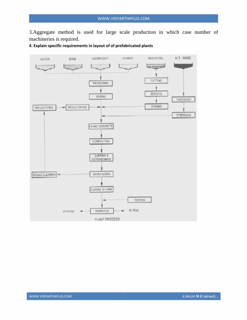
WWWVIDYARTHIPLUSCOM
WWWVIDYARTHIPLUSCOM KBALAJI 119820119812 (119852119853119851119854119836119853)
WWWVIDYARTHIPLUSCOM
WWWVIDYARTHIPLUSCOM KBALAJI 119820119812 (119852119853119851119854119836119853)
5 Explain with neat sketch of the types of shear wall
WWWVIDYARTHIPLUSCOM
WWWVIDYARTHIPLUSCOM KBALAJI 119820119812 (119852119853119851119854119836119853)
WWWVIDYARTHIPLUSCOM
WWWVIDYARTHIPLUSCOM KBALAJI 119820119812 (119852119853119851119854119836119853)
6 What is the code use for prefabricated structures
WWWVIDYARTHIPLUSCOM
WWWVIDYARTHIPLUSCOM KBALAJI 119820119812 (119852119853119851119854119836119853)
7 Explain in detail various design consideration in the design of precast construction
WWWVIDYARTHIPLUSCOM
WWWVIDYARTHIPLUSCOM KBALAJI 119820119812 (119852119853119851119854119836119853)

WWWVIDYARTHIPLUSCOM
WWWVIDYARTHIPLUSCOM KBALAJI 119820119812 (119852119853119851119854119836119853)
5 Explain with neat sketch of the types of shear wall
WWWVIDYARTHIPLUSCOM
WWWVIDYARTHIPLUSCOM KBALAJI 119820119812 (119852119853119851119854119836119853)
WWWVIDYARTHIPLUSCOM
WWWVIDYARTHIPLUSCOM KBALAJI 119820119812 (119852119853119851119854119836119853)
6 What is the code use for prefabricated structures
WWWVIDYARTHIPLUSCOM
WWWVIDYARTHIPLUSCOM KBALAJI 119820119812 (119852119853119851119854119836119853)
7 Explain in detail various design consideration in the design of precast construction
WWWVIDYARTHIPLUSCOM
WWWVIDYARTHIPLUSCOM KBALAJI 119820119812 (119852119853119851119854119836119853)
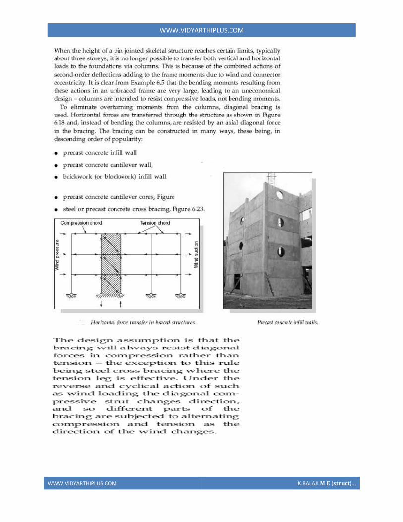
WWWVIDYARTHIPLUSCOM
WWWVIDYARTHIPLUSCOM KBALAJI 119820119812 (119852119853119851119854119836119853)
WWWVIDYARTHIPLUSCOM
WWWVIDYARTHIPLUSCOM KBALAJI 119820119812 (119852119853119851119854119836119853)
6 What is the code use for prefabricated structures
WWWVIDYARTHIPLUSCOM
WWWVIDYARTHIPLUSCOM KBALAJI 119820119812 (119852119853119851119854119836119853)
7 Explain in detail various design consideration in the design of precast construction
WWWVIDYARTHIPLUSCOM
WWWVIDYARTHIPLUSCOM KBALAJI 119820119812 (119852119853119851119854119836119853)
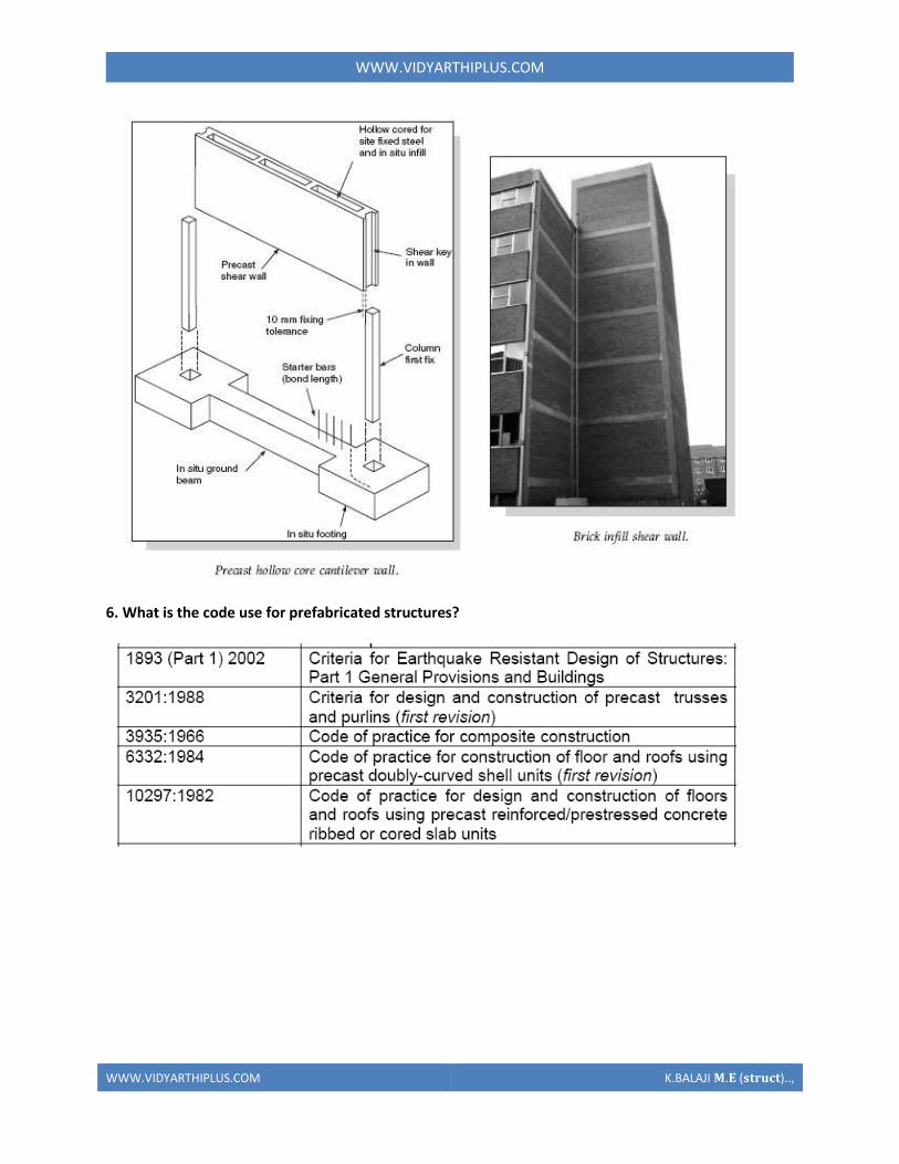
WWWVIDYARTHIPLUSCOM
WWWVIDYARTHIPLUSCOM KBALAJI 119820119812 (119852119853119851119854119836119853)
7 Explain in detail various design consideration in the design of precast construction
WWWVIDYARTHIPLUSCOM
WWWVIDYARTHIPLUSCOM KBALAJI 119820119812 (119852119853119851119854119836119853)
WWWVIDYARTHIPLUSCOM
WWWVIDYARTHIPLUSCOM KBALAJI 119820119812 (119852119853119851119854119836119853)