kawasaki mule pro fxt - kfi31. finish securing wires in the hood compartment, bundle up slack, and...
TRANSCRIPT

INSTALLATION INSTRUCTIONS:PREPARE MACHINE1. Beginbyturningthevehicleoff.Locateandremove
thebatterycompartmentcoveronthepassengerside,behindtherearbench(Figure 1).
Part #: 101230Hardware Kit: HK-129, HK-031Contents:1x 101231-WinchMount1x 101236-SupportChannel
Hardware Kit:4x 3/8”-16x1-1/4”HexFlangeBolt2x 3/8”-16x1”HexFlangeBolt6x 3/8”-16HexFlangedNylockNut1x 22-18GAMaleInsulatedTerminal1x HK-031(UTVMini-RockerHardware)
Page 1 of 5Copyright ©2014 - Kappers Fabricating, Inc. A - 12/1/2014
2. Removeboth the front&rearskidplatesunder thevehicle,and thefronthoodpanel.Figure 12 showsbothskidplatesremoved.
3. RemovethefrontbumperbyunfasteningboltsshowninFigure 2atlocations(A)onbothsidesofframe,andthreeboltsatlocation(B).
Figure - 2
A
B
INSTALL WINCH MOUNT TO FRAME4. Position the winch mount plate against the frame
accordingtoFigure A & Figure 3.First,looselyinstalltwo 3/8” x 1-1/4” Bolts with 3/8” Nylock Nuts atlocation(C1),thentwo3/8”x1”BoltswithNutsatlocation(C2).Donotfully tightenhardwareat thistime.
IMPORTANT: Installation of this winch mount requires KFI Part# UTV-WEK.
Figure - 1
Cover
Latch
Figure - 3
D
C2
C1
Use shorter 3/8” x 1” Bolts at (C2)
KawasakiMuleProFXTWinchMount
Figure - BWinch assembly view.
Figure - A Use short boltson bottom holes.
General assembly diagram.
Support Channel
Page 2 of 5Copyright ©2014 - Kappers Fabricating, Inc. A - 12/1/2014
Passtwo3/8”x1-1/4”Boltsthroughholes(D)inthewinchmountplate,themachineframe,andSupportChannel according to assemblyFigure A. Looselyaffixtwo3/8”NylockNuts.
6. Fullytightenallwinchmounthardwareevenly.INSTALL WINCH TO WINCH MOUNT7. Assemble your winch, fairlead bracket, and roller
fairlead or hawse fairlead to the winch mount asshown in Figure B using hardware included withyourwinch.Note: If your winch did not come with a roller fairlead or fairlead bracket, you can purchase either separately. See www.kfiproducts.com or contact your local dealer.
8. Replace front bumper, using hardware removed inStep 3.
WIRING INSTRUCTIONS:OVERVIEW
Installation requires the use of KFI #UTV-WEK (Extended Wiring Kit). All wiring will first be routed from the hood compartment where the Contactor Block is mounted through a small wiring outlet (E), then either to the battery or the winch.
Leave all ends loose until instructed to connect them. You will then work your way back to the front while securing wires to the frame and pulling slack into the hood compartment.
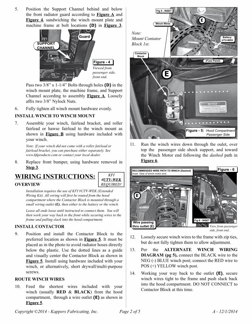
INSTALL CONTACTOR9. Position and install the Contactor Block to the
preferredlocationasshowninFigure 5. Itmustbeplacedasinthephototoavoidradiatorhosesdirectlybelow the plastic. Use the dotted lines as a guideandvisuallycentertheContactorBlockasshowninFigure 5.Installusinghardwareincludedwithyourwinch, or alternatively, short drywall/multi-purposescrews.
ROUTE WINCH WIRES10. Feed the shortest wires included with your
winch (usually RED & BLACK) from the hoodcompartment,throughawireoutlet (E)asshowninFigure 5.
11. Run thewinchwires down through the oulet, overtop the passenger side shock support, and towardtheWinchMotor end following thedashed path inFigure 6.
12. Looselysecurewinchwirestotheframewithzipties,butdonotfullytightenthemtoallowadjustment.
13. Per the ALTERNATE WINCH WIRING DIAGRAM (pg 5),connecttheBLACKwiretotheNEG(-)BLUEwinchpost;connecttheREDwiretoPOS(+)YELLOWwinchpost.
14. Working your way back to the outlet (E), securewinchwires tight to the frameandpushslackbackintothehoodcompartment.DONOTCONNECTtoContactorBlockatthistime.
5. Position the Support Channel behind and belowthe front radiator guard according toFigure A andFigure 4, sandwiching the winch mount plate andmachine frame at bolt locations (D) in Figure 3.
SUPPORT CHANNEL
Figure - 4Viewed from passenger side, front end.
Guard
Figure - 6
View from passenger side, front end.
Wire passing thru outlet (E)
Fan
Shock
Radiator
E
RECOMMENDED WIRE PATH TO WINCH (Dashed)Inset: View of winch motor end.
Fig 6 - INSET
WinchMotor
Figure - 5: Hood Compartment Passenger Side
E
E
Fig 5 - INSET
Winch Wires
Battery:UTV-WEK
ContactorBlock
(Fuse Panel)
Note:Mount Contator Block 1st.
KFI#UTV-WEKREQUIRED!

Page 3 of 5Copyright ©2014 - Kappers Fabricating, Inc. A - 12/1/2014
INSTALL SWITCH15. Use included Mini-Rocker Switch Hardware Kit
(HK-031)tofastenahandlebarmountedmini-rockerswitchtothedashoranydesiredlocation.
a. Remove handlebar mount hardware from the switch.
b. Locate desired mounting location.
c. Mark & drill 2 switch holes thru dash using switch housing as a template.
d. Drill a 3rd hole for switch wiring.
e. Assemble per Figure 7.
16. ConnecttheredignitionfedwireforaMini-RockerSwitchorothercontroller to theorange terminaloftheauxilliarywiringharness that ispre-installedonthe passenger side in the front hood compartment.See Figure 8.Attach using the supplied 22-18GA Male Insulated Terminal. Wire to Contactor peryourwinchmanual.Securewiresasneeded.
ROUTE BATTERY WIRESYou will route the wires from UTV-WEK to the battery along the same path as the parking brake wire bundle. (See Fig 11)
17. This vehicle requires extended 11FT batterywires included with the Wire Extension Kit(KFI#: UTV-WEK, sold separately).Use only theBLUE & YELLOW color coded wires found inUTV-WEKtoconnectthebattery.
18. Feedthewiresfrom#UTV-WEKthroughoutlet(E)in the hood compartment shown inFigure 5, thendownbehindthefan,goingfromthepassengersidestrutsupport toward thedriversideand theparkingbrakewirebundleasshowninFigure 9.
20. Locateawirebundle(Figure 10)andfollowitspathunderthevehicle.RoutetheUTV-WEKwiresalong this cable bundle(asshowninFigure 11)towardstherearofthevehicletothebatterycompartment.Usingzip ties, looselysecure theUTV-WEKwires to thewire bundle and pass it through the following keyjunctionpoints:
21. Point F - Passing under the front differential (seeFigure 10).
Figure - 7
19. Before moving on to the next steps, tape off the YELLOW wire end left in the hood compartmentwithelectricaltapeforsafety.Youwillbeconnectingthese wires to the battery once they are routedproperly,andthispreventsarcing.
Figure - 8
Aux Hot Wire (Orange)
E
FRONT
Driver Side
Figure - 9
E
Rad
iato
r + F
an
UTV-WEKWires
Wire
Bun
dle
FRONT
F
Figure - 10
Wire Bundle
FrontDifferential
Figure - 11 View from below vehicle w/ skid plates removed.
WIRE BUNDLE
PATH
FRONT
Driver Side
Passenger Side
L
J
H
G
F
K

Page 4 of 5Copyright ©2014 - Kappers Fabricating, Inc. A - 12/1/2014
23. Point H - Across and on top of a tube support(seeFigure 13).
24. Point J-Throughahanger(seeFigure 14).25. Point K-SpecialNote:KFIrecommendsusinga12”
WireLoomontheUTV-WEKwires in the locationwherethewirescrosspathswiththeradiatorlinesatpoint(K).
26. Point L-Intothebatterycompartment;feedbothendsofthewiresfromUTV-WEK,fromunderthevehicle,upthroughaholefoundatlocation(L)directlyabovethewirebundleasshowninFigure 15.
27. Per the ALTERNATE WINCH WIRING DIAGRAM,attachtheYELLOWwiretothescrewonthePOS(+)batterypost.AttachtheBLUEwiretotheNEG(-)batterypost.
28. Working your way back to the front hoodcompartment,pullwirestaughtandtakeoutanyslackasyougo.Secure themwithadditionalzip tiesandtightenlooselyplacedziptiesfromearliersteps.Note: Keep battery wires tight & secure against the wire bundle! DO NOT let them come in contact with any heat source or moving components!
COMPLETING INSTALLATION29. Inthehoodcompartment,finallyconnectthewinch
and battery wires to the Contactor Block per theALTERNATE WINCH WIRING DIAGRAMshownonPage 5.Note: Remove the electrical tape from the YELLOW wire end applied in Step 19 before making connections!
• Wire Winch NEG (BLACK WIRE) to BLUE Contactor post.
• Wire Winch POS (RED WIRE) to YELLOW Contactor post.
• Wire Battery NEG (BLUE WIRE) to BLACK Contactor post.
• Wire Battery POS (YELLOW WIRE) to RED Contactor post.
30. Ifapplicable,connectthesmallGREEN&BLACKwires from aMini-Rocker switch or similar to thestandard Contactor Block. Consult your Winchmanualforspecificwiringinstructions.
31. Finish securing wires in the hood compartment,bundleupslack,andzip tieasneeded.Replace thehoodpanel.
32. Replaceskidplatesremovedinprevioussteps.33. Replacebatterycompartmentcover.
22. Point G - Through a wire hole in the plastic(seeFigure 12).
Figure - 15Neg (-)
Pos (+)(Remove Boot)
L
Figure - 12
G
Figure - 13
H
TUBESUPPORT
Figure - 14
Hanger
J
K

Page 5 of 5Copyright ©2014 - Kappers Fabricating, Inc. A - 12/1/2014
Figure - 16
Note: Battery shown in this diagram represents a battery fed source. Depending on your vehicle configuration, power leads may attach to a primary/secondary battery or starter solenoid. Follow all vehicle specific installation instructions.