katflow 150 - daly-me.com
TRANSCRIPT

Page 1 of 13
Clamp-On Ultrasonic Flowmeter
KATflow 150
Flowmeter with one or two measurement
channels, graphic LCD display, internal
datalogger and input/output options
For commonly used pipe materials and
diameters from 10 mm to over 3.0 m
Intuitive menu, Setup Wizard and Audible
Sensor Positioning Assistant TM for easy
and quick setup and installation
Transit-time correlation measurement
using dual DSP-technology for better
measurement accuracy
Heat Quantity Measurement capability
and Ex approved instrument versions
AC, DC and solar panel power supply
Features Lockable and sturdy IP 67 transmitter enclosure with keypad and multifunctional display
Bi-directional measurement with totalizer function and process input, output and serial
communication options including Modbus and HART
Available with optional Heat Quantity Measurement function and PT100 clamp-on sensors
for contactless metering of thermal energy consumption
Optional Sound Velocity Measurement and output function for contactless product
recognition and interface detection
Transmitter and transducer options approved for use in hazardous areas Zone 1 or 2
KATdata+ software for offline/online data transfer via RS 232 or USB cable
AC, DC, battery and solar panel power supply options available
The KATflow clamp-on ultrasonic flow meters work on the transit-time method. This is based
on the principle that sound waves travelling with the flow will move faster than those travelling
against it. The resulting difference in transit-time is directly proportional to the flow velocity of
the liquid and consequently to the volumetric flow rate.
The ultrasonic transducers (sensors) of the flow meter are mounted on the external surface of
the pipe and are used to generate and receive pulses. The flowing liquid within causes time
differences in the ultrasonic signals, which are evaluated by the flow meter to produce an
accurate flow measurement. The advanced electronics of the flow meter compensate for and
adapt to changes in the flow profile and medium temperature to deliver reliable measurements.
The KATflow 150 is a fixed-installation clamp-on ultrasonic flow meter for non-invasive and non-
intrusive flow measurement of liquids and liquefied gases in fully filled pipes. It can be supplied
with one or two measurement channels. This enables the flow meter to simultaneously monitor
up to two separate pipes. Alternatively, a dual-channel setup can be used for a multi-path
mounting configuration of the sensors on one single pipe. Additionally, the KATflow 150 offers
optional functions for heat quantity and concentration measurement with process input, output
and serial communication options available. These features are complemented by an optional
internal datalogger and software for the recording and download of measured values. Thanks
to its intuitive instrument menu, Setup Wizard, and TM the
flow meter can be set up and its sensors correctly installed in a matter of minutes. Optional
transmitter and transducer versions are available for installation in hazardous areas.
Description

Page 2 of 13
Measurement principle : Ultrasonic transit-time difference correlation
Flow velocity range : 0.01 ... 25 m/s
Resolution : 0.25 mm/s
Repeatability : 0.15 % of measured value, ±0.015 m/s
Accuracy :
±1 ... 3 % of measured value depending on application
±0.5 % of measured value with process calibration
±0.5 % of measured value
Turn down ratio : 1/100
Measurement rate: : 10 ... 1000 s-1
Response time : 1 s, 70 ms (optional)
Damping of displayed
value : 0 ... 99 s
Gaseous and solid
content of liquid media : < 10 % of volume
Specification: Transmitter
Performance
Enclosure type : Wall mounted
Degree of protection : IP 66 according to EN 60529
Operating temperature : -10 ... 60 °C (14 ... 140 °F)
Housing material : Plastic, ABS, Polycarbonate (transparent front door)
Measurement channels : 1 or 2
Calculation functions : Average, difference, sum, highest (dual-channel use only)
Power supply : 100 ... 240 V AC 50/60 Hz
9 ... 36 V DC
Special solutions (e.g. solar panel, battery) upon request
Display : LCD graphic display, 128 x 64 dots, backlit
Dimensions : 237 (h) x 258 (w) x 146 (d) mm
Weight : Approx. 2.3 kg
Power consumption : < 5 W
Operating languages : English, German, French, Spanish, Russian
General
Drawings

Page 3 of 13
Specification: Transmitter (continued)
Images
Communication Type : RS 232, USB converter cable (optional), RS 485 (optional),
Modbus RTU (optional), HART output (optional)
Transmitted data : Measured and totalized value, parameter set and
configuration, logged data
Internal data
loggerStorage capacity : Approx. 30,000 data items (128 kByte)
Approx. 100,000 data items (512 kByte)
Logged data : All measured and totalized values, parameter sets
KATdata+
softwareFunctionality : Download of measured values/parameter sets, graphical
presentation, list format, export to third party software,
online transfer of measured data
Operating systems : Windows 7, Vista, XP, NT, 2000
Linux
Mac (optional)
Quantity & units
of measurement
Volumetric flow rate : m3/h, m3/min, m3/s, l/h, l/min, l/s, USgal/h (US gallons per
hour), USgal/min, USgal/s, bbl/d (barrels per day), bbl/h,
bbl/min
Flow velocity : m/s, ft/s, inch/s
Mass flow rate : g/s, t/h, kg/h, kg/min
Volume : m3, l, gal (US gallons), bbl
Mass : g, kg, t
Heat flow : W, kW, MW (only with Heat Quantity Measurement option)
Heat quantity : J, kJ, MJ (only with Heat Quantity Measurement option)

Page 4 of 13
Specification: Transmitter (continued)
Process inputs Temperature : PT100 (clamp-on sensors), four-wire circuit, measurement
range -50 ... 400 °C (-58 ... 752 °F), resolution 0.1 K,
accuracy ±0.2 K
Current : 0/4 ... 20 mA active or 0/4 ... 20 mA passive, U = 30 V,
Ri = 50 , accuracy 0.1 % of measured value
Note : All process inputs galvanically isolated from main
electronics and from other inputs and outputs.
Process outputs Current : 0/4 ... 20 mA active (RLoad < 500 ), 16 bit resolution,
U = 30 V, accuracy = 0.1 %
Voltage : 0 ... 10 V, Ri = 500 (optional upon request)
Digital Open-Collector : Totaliser, value 0.01 ... 1000/unit, width 30 ... 999 ms,
U = 24 V, Imax = 4 mA
Digital relay : Alarm, fault (programmable), Form C (SPDT-CO) contacts,
U = 48 V, Imax = 250 mA
Note : All process outputs galvanically isolated from main
electronics and from other inputs and outputs.
Drawings
Page 5 of 13
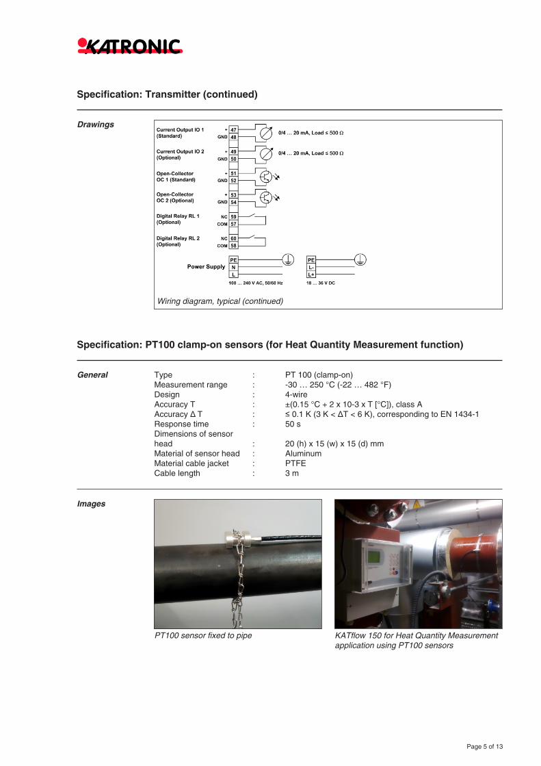
Specification: Transmitter (continued)
Drawings
Specification: PT100 clamp-on sensors (for Heat Quantity Measurement function)
Type : PT 100 (clamp-on)
Measurement range : -30 … 250 °C (-22 … 482 °F)
Design : 4-wire
Accuracy T : ±(0.15 °C + 2 x 10⁻³ x T [°C]), class A
Accuracy T : 0.1 K (3 K < T < 6 K), corresponding to EN 1434-1
Response time : 50 s
Dimensions of sensor
head : 20 (h) x 15 (w) x 15 (d) mm
Material of sensor head : Aluminum
Material cable jacket : PTFE
Cable length : 3 m
General
Images

Page 6 of 13
Specification: Hazardous area transmitter enclosure
General Enclosure type : Wall mounted (additional to KATflow 150 transmitter)
Degree of protection : IP 66 according to EN 60529
Operating temperature : -20 ... 40 °C (-4 ... 104 °F)
Housing material : Grade LM6 cast alloy
Finish : RAL 7035 epoxy powder coat
Dimensions: : 358 (h) x 278 (w) x 268 (d) mm
Weight : Approx. 20.0 kg (with KATflow 150 transmitter)
Ex certification code : Ex II 2 GD Ex-d IIB+ H2 T4/T5/T6 IP65/66/67
Ex certification number : CESI 01 ATEX 027
Drawings and
images

Page 7 of 13
Specification: Transducers
K1L, K1N, K1E Pipe diameter range : 50 ... 3000 mm for type K1N/E
50 ... 6500 mm for type K1L
Dimensions of sensor
heads : 60 (h) x 30 (w) x 34 (d) mm
Material of sensor heads : Stainless steel
Material of cable conduits :
PVC
Stainless steel
Temperature range :
-30 ... 80 °C (-22 ... 176 °F)
-30 ... 130 °C (-22 ... 266 °F)
-30 ... 200 °C (-22 ... 392 °F)
for short periods up to 300 °C (572 °F)
Degree of protection : IP 66 acc. EN 60529, (IP 67 and IP 68 upon request)
Standard cable lengths :
5.0 m
4.0 m
Drawings and
imagesWith SMB connection
With direct cable connection

Page 8 of 13
Specification: Transducers (continued)
K4L, K4N, K4E Pipe diameter range : 10 ... 250 mm for type K4N/E
10 ... 250 mm for type K4L
Dimensions of sensor
heads : 43 (h) x 18 (w) x 22 (d) mm
Material of sensor heads : Stainless steel
Material of cable conduits :
PVC
Stainless steel
Temperature range :
-30 ... 80 °C (-22 ... 176 °F)
-30 ... 130 °C (-22 ... 266 °F)
-30 ... 200 °C (-22 ... 392 °F)
for short periods up to 300 °C (572 °F)
Degree of protection : IP 66 acc. EN 60529, (IP 67 and IP 68 upon request)
Standard cable lengths :
5.0 m
2.5 m
Drawings and
imagesWith SMB connector
With direct cable connection

Page 9 of 13
Specification: Transducers (continued)
Extension cable Available lengths : 5.0 ... 100 m
Cable type : Coaxial
Material cable jacket : TPE
Operating temperature : -40 ... 80 °C (-40 ... 176 °F)
Min. bend radius : 67 mm
Connection types : Junction box, Amphenol connectors
Termination into
transmitter : SMB connector (SubMiniature version B),
direct cable connection (terminal block)
Drawings
Cable connection
Top: K1 transducers connected via junction box to extension cable and terminating into transmitter via direct cable connection
Bottom: K4 transducers terminating via direct cable connection
Top: K1 transducers connected via Amphenol connectors to extension cable and terminating into transmitter via SMB connectors
Bottom: K4 transducers with Amphenol connector (terminal termination via SMB connectors only)

Page 10 of 13
Specification: Hazardous area transducers
K1Ex and K4Ex
Drawings and
images
Pipe diameter range : 10 ... 250 mm for type K4Ex
10 ... 3000 mm for type K1Ex
Dimensions of sensor
heads : 60 (h) x 30 (w) x 34 (d) mm
Material of sensor heads : Stainless steel
Material of cable conduits : PTFE
Temperature range : -50 ... 115 °C (-4 ... 248 °F)
Standard cable length : 5.0 m
Degree of protection : IP 68 acc. EN 60529
Ex certification code : II 2 G Ex mb IIC T4-T6 X, II 2 D Ex mbD 21
Ex certification number : TRAC09ATEX21226X
Ex protection method : Encapsulation
The transducers are approved for use in hazardous areas
classified as Ex Zone 1 and 2. They are connected to the
transmitter via extension cables and Ex approved junction
boxes. The transmitter can be installed in a safe area or -
if equipped with the additional Ex enclosure - together with
the transducers in an hazardous environment (see hazar-
dous area enclosure for KATflow 150 transmitter, page 6).
Hazardous area transducers K1Ex and K4Ex with junction box and direct cable connection.

Page 11 of 13
Diameter range and
mounting types :
DN 10 ... DN 40
DN 15 ... DN 310
DN 25 ... DN 3000
DN 1000 ... DN 3000 (6500)
DN 50 ... DN 3000
Mounting fixure for
flexible hoses : Custom made mounting bracket, stainless steel
(available upon request)
Images
Specification: Transducer mounting accessories
General

Page 12 of 13
Configuration code: Transmitter and accessories
KF150 Ultrasonic flow meter KATflow 150, serial interface RS 232, operating instructions
Number of measurement channels
1 1 measurement channel
2 2 measurement channels 1)
Power supply
1 100 ... 240 V AC, 50/60 Hz
2 9 ... 36 V DC
Z Special (please specify)
Enclosure type
1 Plastic ABS, wall mount, IP 66
2 Ex enclosure, powder coated LM6 cast alloy, IP 67
Z Special (please specify)
Communication
0 Without
1 RS 485 serial interface, Modbus RTU (please consult factory)
2 HART output, 0/4 ... 20 mA, active (please consult factory)
Z Special (please specify)
Analogue outputs
C1 1 x current 0/4 ... 20 mA, active, (standard)
C2 2 x current 0/4 ... 20 mA, active
Digital Open-Collector outputs
D1 1 x digital Open-Collector, (standard)
D2 2 x digital Open-Collector
Digital relay outputs
N Without
R1 1 x digital relay
R2 2 x digital relay
Temperature inputs 2)
N Without
A2 2 x PT100 temperature inputs
Analogue inputs
N Without
B2 2 x current input 0/4 ... 20 mA, active/passive
Z Special (please specify)
Internal data logger
0 Without
1 30,000 data items
2 100,000 data items
Z Special (please specify)
eat Quantity Measurement (HQM) 2)
0 Without
1 With HQM incl. 2 x PT100 clamp-on
sensors
Z Special (please specify)
Sound Velocity Measurement (SVM) 3)
0 Without
1 With SVM
Optional items
Ex Suitable for connection with Ex
sensors
SW Download software KATdata+
and RS 232 cable
SU Download software KATdata+
and USB cable
KF150 1 1 1 0 C1 D1 N N N 0 0 0 / (example configuration)
The configuration is customised by choosing from the above-listed options and is expressed by the resulting code at
the bottom of the table.1) For simultaneous measurement on two seperate pipes or for measurement on one single pipe in a multi-path sensor mounting configuration.2) For contactless measurement of thermal energy consumption. Always select both options.3) For contactless product recognition and interface detection.
– – – – – – – – –

Katronic Technologies Limited I 23 Cross StreetLeamington Spa I CV32 4PX I United Kingdom
Phone: +44 (0)1926 882 954Fax: +44 (0)1926 338 649
Email: [email protected]: www.katronic.co.uk
Subject to changes without prior notice.Issue: DataSheetKATflow150_V20_E1110_121110.
© Copyright Katronic Technologies Ltd. 2010 I All rights reserved.
Page 13 of 13
Configuration code: Transducers and accessories
K1 Transducer pair, pipe diameter range 50 ... 3000 mm (K1L: 50 ... 6500 mm)
K4 Transducer pair, pipe diameter range 10 ... 250 mm
Z Special (please consult factory)
Temperature range
L Process temperature -30 ... 80 °C, including accoustic coupling paste
N Process temperature -30 ... 130 °C, including accoustic coupling paste
E Process temperature -30 ... 200 °C, including accoustic coupling paste
Ex Process temperature -50 ... 115 °C, including accoustic coupling paste
Z Special (please consult factory)
Internal code
x Version number (internal code)
Degree of protection
1 IP 66 (standard)
2 IP 67 (please consult factory)
3 IP 68 (please consult factory)
Z Special (please consult factory)
Transducer mounting accessories
0 Without
1 Clamping set DN 10 ... 40
2 Metallic straps and clamps DN 15 ... 310
3 Metallic straps and clamps DN 25 ... 3000
4 Metallic straps and clamps DN 1000 ... 6500
5 Metallic mounting rail and straps DN 50 ... 3000
Z Special (please consult factory)
Stainless steel tag
0 Without
1 With stainless steel tag
Transducer connection and extension cables
0 Direct SMB/cable termination
A Extension via Amphenol connectors (not available for Ex sensors)
J Extension via junction box
C005 Extension cable length 5 m
C010 Extension cable length 10 m
C020 Extension cable length 20 m
C___ Specify length in meters
Z Special (please specify)
Optional items
CA 5-point calibration with certificate
ZZ Special (please specify)
K1 N x 1 3 0 J C010 / (example configuration)
The configuration is customised by selecting the above-listed options and is expressed by the resulting code at the
bottom of the table.
– – – – –