kastrup taitto 2001 05 11 - bauforumstahl e. v. · une zone tropicale et une autre tempérée, il...
TRANSCRIPT
Architecture Steel Stahl Acier 14
Steel Stahl Acier
14
Architecture
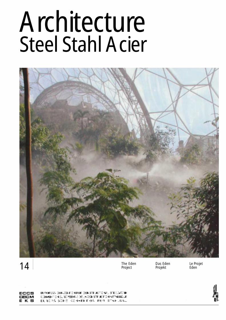
The EdenProject
Das EdenProjekt
Le ProjetEden

Architecture Steel Stahl Acier 14
Eden
ECCS N° 91-14ISBN 92-9147-000-73
All rights reserved.No part of this publication may be reproduced in anymanner whatsoever without permission in writingfrom ECCS.
Tous droits réservés.Aucune partie de ce document ne peut être reproduitesans autorisation écrite de la CECM.
Alle Rechte vorbehalten.Kein Teil dieser Publikation darf ohne schriftlicheZustimmung der ECCS in jedwelcher Form vervielfältigtwerden.
Eden EdenProjectPlanthouseCornwall, UK
ClientEden Project Limited
ArchitectsNicholas Grimshaw &Partners Ltd.
Structural engineersAnthony Hunt Associates
Climatisation of thebiomesOve Arup & Partners
Metal structuresMero GmbH
ProjektGewächshäuserCornwall, Großbritannien
BauherrEden Project Limited
ArchitektenNicholas Grimshaw &Partners Ltd.
TragwerksplanungAnthony Hunt Associates
Klimatisierung der BiomesOve Arup & Partners
MetallstrukturenMero GmbH
ProjetSerreCornouailles, Angleterre
Maître d’ouvrageEden Project Limited
ArchitectesNicholas Grimshaw &Partners Ltd.
Ingénieurs structureAnthony Hunt Associates
Climatisation des biomesOve Arup & Partners
Structures métalliquesMero GmbH

1Architecture Steel Stahl Acier 14
The Project
The Eden Project, a showcase for global di-versity located in the remote county ofCornwall, is the largest plant enclosure inthe world, recreating tropical and warmtemperate habitats. It was the brainchild ofTim Smit, who had previously been respon-sible for the renewal of Cornwall’s ‘LostGardens of Heligan’, and Jonathan Ball, alocal architect. Their aspiration was to bringto the public the fascinating story of man’srelationship with plants through a non-prof-it making charitable scientific organisation.
The development was based in Cornwallfor a number of reasons: the mild climatehelps to achieve the ideal growing condi-tions inside the plant houses, the high levelsof unemployment in the area would benefitfrom the presence of the project, and therewere a number of suitable sites availablewith good road and rail access. The particu-lar location selected – the Boldeva Pit – wasa china clay pit which was approaching theend of its commercial life as a quarry, andthis gave the further benefit of land recla-
Das Eden Projekt, eine Ausstellung der Viel-seitigkeit unserer Welt, liegt in einem abge-legenen Teil von Cornwall, ist der Weltgrößte Anlage für Pflanzen und beinhaltetZonen vom Wüsten- bis zum tropischen Kli-ma. Es war das geistige Kind von Tim Smit,der bereits vorher für die Erneuerung der“Lost Gardens of Heligan” verantwortlichwar und von Jonathan Ball, einem ortsan-sässigen Architekten. Ihre Vorstellung war,der Allgemeinheit die faszinierende Ge-schichte des Zusammenlebens von Men-schen und Pflanzen näherzubringen unddies durch eine nicht gewinnorientierte,wohltätige und wissenschaftliche Organisa-tion.
Das Projekt wurde aus mehreren Grün-den in Cornwall angesiedelt: das milde Kli-ma begünstigt ideales Wachstum innerhalbder Wintergärten, der hohe Stand der Ar-beitslosigkeit innerhalb der Region würdedurch das Projekt vermindert und es gabeine Reihe von zufriedenstellenden Standor-ten mit guten Straßen- oder Bahnverbin-
Das Eden Projekt
1
1 Aerial view
1 Luftaufnahme
1 Vue aérienne
© R
icha
rd K
alin
a
Réalisé dans une région isolée de Cor-nouailles, le projet Eden est le plus grandjardin botanique du monde. Comprenantune zone tropicale et une autre tempérée,il illustre bien la diversité de notre monde.On doit cette idée originale à Tim Smit quis’était auparavant occupé de la restaurationdes Lost Gardens of Heligan et à JonathanBall, un architecte local. Ils souhaitaient fairepartager au public leur fascination pour lesrapports entre l’homme et les plantes, et cepar le biais d’un organisme scientifique àbut non lucratif.
Le projet a vu le jour en Cornouaillespour des raisons diverses : tout d’abord, ladouceur du climat y est gage de conditionsde croissance idéales dans les serres ;ensuite il permettait de créer des emploisdans une région connaissant un fort taux dechômage ; et, enfin, il y avait un grandnombre de sites possibles bénéficiant d’ac-cès routiers et ferroviaires aisés. L’emplace-ment finalement retenu, à Boldeva, étaitune carrière de kaolin dont l’exploitation
Le projet Eden

2 Architecture Steel Stahl Acier 14
mation. The pit covered an area of about15ha and presented a dramatic landscape,including significant south-facing rockslopes which would help to create the de-sired climatic conditions. The concealed ap-proach to the site would also add to thedrama experienced by visitors as they enterthe project.
The primary design objective was to cre-ate the correct environment for growth us-ing minimum water and energy. The key is-sues for the enclosures were orientation,natural lighting and heating, and maximumrecycling of water.
Nicholas Grimshaw & Partners were ap-pointed as architects for the project and de-veloped a prototype for the plant houses,inspired by the sinuous, asymmetric form oftheir design for the International Terminal,Waterloo. This had been widely acclaimed,and the scheme design presented was in-strumental in securing funding, enablingthe project to proceed in detail.
dungen. Der schließlich gewählte Standort -der Bodeva Pit- war eine Kaolingrube, derenkommerzielles Ende mit Streit verbundenwar, was den Landerwerb begünstigte. DieGrube hatte eine Fläche von ungefähr 15ha und zeigte eine bewegte Landschaft mitsignifikanten, südseitig gelegenen Felshän-gen, die sich für die Schaffung der ge-wünschten Klimabedingungen gut eigne-ten. Der abgelegene Eingang zum Geländeträgt zum dramatischen Erlebnis der Besu-cher bei der Annäherung bei.
Das vorrangige Entwurfsziel war, richtigeWachstumsbedingungen bei einem Mini-malaufwand von Wasser und Energie zuschaffen. Dies wurde erreicht durch maxi-male Nutzung von natürlicher Belichtung,sowie durch maximales Recycling von Was-ser.
Nicolas Grimshaw & Partners wurden alsArchitekten ausgewählt und entwickelteneinen Prototyp für die Gewächshäuser, ähn-lich ihrem Entwurf für die gekrümmte,asymmetrische Form des International Ter-minal Waterloo in London. Dieser wurdeweithin anerkannt und der vorgelegte Ent-wurf war gut geeignet, die Geldmittel zu si-chern und die Detailplanung fortzuführen.
2 3
M.
Dye
r A
ssoc
iate
s
commerciale touchait à sa fin et qui allaitdonc nécessiter un réaménagement paysa-ger. La mine à ciel ouvert s’étendait sur unesuperficie d’environ 15 ha et présentait unterrain très accidenté avec des falaisesorientées au sud offrant des conditions fa-vorables pour les installations climatiquesenvisagées. L’isolement du site contribueégalement à impressionner le visiteur parson côté spectaculaire.
L’idée de base du projet était d’offrir auxplantes les conditions idéales de croissancetout en économisant au maximum l’eau etl’énergie. On a atteint cet objectif en recou-rant le plus possible à la lumière et à la cha-leur solaires et en recyclant l’eau.
On a confié le projet au cabinet d’archi-tecture Nicolas Grimshaw & Partners qui aconçu un type original de serre s’inspirantde la forme sinueuse et asymétrique de leurgare internationale de Waterloo à Londres.Cette réalisation leur avait valu un concertde louanges et leur nouveau projet possé-dait toutes les qualités requises pour en as-surer le financement et en poursuivre l’étu-de de détail.

3Architecture Steel Stahl Acier 14
Planning
The project includes three principal structur-al elements encapsulating two plant hous-es, and a link building connecting the two.The plant houses, which recreate quite dif-ferent atmospheres – one providing a hu-mid tropical region, the other a warm tem-perate region – are accommodated withinseparate ‘biomes’, each an amalgam ofgreat transparent domes, rising up to 55mabove the ground. The exact location of thebiomes on site was determined by solarmodelling, a sophisticated technique whichindicated where the structures would bene-fit most from passive solar gain. A separatebuilding houses the Visitors’ Centre on ahilltop providing a gateway to the site.
The site provided a dramatic landscape,and the brief was to maintain as much ofthe wild, rugged appearance as possiblewhile creating a safe, stable environmentfor visitors. A digital ground model basedon aerial survey data was used to sculpt thepit, to create terraces around the perimeterfor access and parking. This involved cutand fill operations for approximately800 000 m3 of material, and deliberatelyavoiding the movement of material ontoor off the site.
Das Projekt besteht aus drei Strukturele-menten und zwar aus zwei Gewächshäu-sern und einem Verbindungsbau dazwi-schen. Die Gewächshäuser, die sehr ver-schiedene Umgebungen erzeugen, – daseine erzeugt eine feuchte, tropische, dasandere eine warme, gemäßigte Umwelt –sind in getrennten ”Biomes” untergebracht,jedes eine Gruppe von großen, transparen-ten Kuppeln mit Höhen bis zu 55 m. Die ge-nauen Standorte wurden durch Solarsimula-tionen festgelegt, eine hochentwickelteTechnologie, die anzeigt, wo die Strukturenam meisten vom natürlichen Sonneneinfallprofitieren. Ein getrenntes Gebäude be-inhaltet das Besucherzentrum. Es liegt aufeinem Hügel und ist mit einem überdachtenZugang zum Ensemble ausgestattet.
Das Terrain bildet eine äußerst bewegteLandschaft und es war beabsichtigt, sovielals möglich von dem wilden, zerklüftetenErscheinungsbild zu erhalten und dem Be-sucher dennoch eine sichere und gleichblei-bende Umwelt zu bieten. Ein auf Luftauf-nahmen basierendes, digitales Bodenmodellwurde verwendet, um die Grube zu model-lieren, um Terrassen für Zufahrten und Park-plätze zu schaffen. Dies erforderte Boden-bewegungen von ca. 800.000 m3 Material,ohne daß Material an- oder abtransportiertwurde.
Die Planung
4
2 Site plan
3 Aerial view of the site
4 The approach to Eden
2 Lageplan
3 Luftaufnahme desGeländes
4 Der Zugang zu Eden
2 Plan de masse
3 Vue aérienne
4 L’arrivée au site
Aru
p /
Gra
ham
Gau
ntLe projet se compose de trois zones diffé-rentes : deux serres et un bâtiment deliaison. Les serres qui recréent deux bioto-pes bien différents – l’un humide et tropical,l’autre, tempéré – sont formées par deuxbiodômes séparés, faits de la juxtapositionde grands dômes transparents dont la hau-teur, au point culminant, atteint 55 mètres.Leur position exacte a été déterminée avecsoin grâce à une technologie de simulationsolaire des plus sophistiquées pour faire ensorte que les installations profitent au maxi-mum de la lumière naturelle. Un bâtimentséparé constitue le Centre des visiteurs ; ilse dresse sur une colline voisine et permetd’accéder, à l’abri des intempéries, à l’en-semble des installations.
Le terrain forme un paysage plutôt acci-denté et l’on s’est efforcé d’en conserver aumaximum l’aspect sauvage, crevassé, touten offrant au visiteur un environnement sûret stable. On a utilisé une maquette numéri-sée du terrain, obtenue grâce à des photo-graphies aériennes, pour aménager la car-rière et dessiner des terrasses alentour pourles accès et les parkings. Pour y parvenir, il afallu néanmoins remuer quelque 800 000m3 de terre mais sans avoir à en apporterou à en enlever.
Le plan
4 Architecture Steel Stahl Acier 14
9
10
5 6 7 8
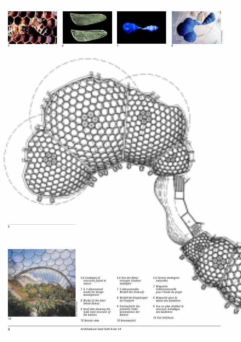
5,6 Analogies ofstructures found innature
7 A 3-dimensionalmodel for designdevelopment
8 Model of the inter-linked domes
9 Roof plan showing themain steel structure ofthe biomes
10 Interior view
5,6 Von der Naturerzeugte Struktur-analogien
7 3-dimensionalesModell des Entwurfs
8 Modell der Kopplungender Kuppeln
9 Dachaufsicht derprimären Stahl-konstruktion derBiomes
10 Innenansicht
A.
Hun
t A
ssoc
iate
s
Aru
p /
Gra
ham
Gau
nt
5,6 Formes analoguesnaturelles
7 Maquettetridimensionnellepour l’étude du projet
8 Maquette pour laliaison des biodômes
9 Vue en plan révélant lastructure métalliquedes biodômes
10 Vue intérieure
5Architecture Steel Stahl Acier 14
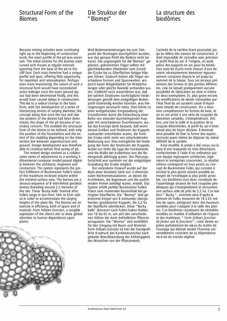
Structural Form of theBiomes
Because mining activities were continuingright up to the beginning of constructionwork, the exact profile of the pit was uncer-tain. The initial scheme for the biomes usedcurved arch trusses at regular intervalsspanning from the base of the pit to thecliff face. Each truss therefore had a uniqueprofile and span, offering little opportunityfor repetition and rationalisation. Perhapseven more importantly, the nature of such astructural form would have necessitatedsome redesign once the exact ground lay-out had been determined finally, and thiswould have caused delays in construction.This led to a radical change to the basicform, with the development of a series ofintersecting domes of varying diameter, theconcept being that once the size and rela-tive position of the domes had been deter-mined, the shape of the pit became of sec-ondary concern. This enabled the structuralform of the domes to be defined, with onlythe position of the foundations and the ex-tent of the cladding depending on the inter-section line between superstructure andground. Design development was thereforeable to continue before final survey of pit.
The revised design evolved as a collabo-rative series of adjustments to a working 3-dimensional computer model passed digital-ly between the architects, engineers andcontractors. The system represents the per-fect fulfilment of Buckminster Fuller’s visionof the maximum enclosed volume withinthe minimal surface area. The biomes are asinuous sequence of 8 inter-linked geodesicdomes threading around 2.2 hectares ofthe site. These ‘Bucky balls’ (named afterFuller) range in size from 18m to 65m radi-us in order to accommodate the varyingheights of the plant life. The biomes are anexercise in efficiency, both of space and ofmaterial. Form follows function, a tangibleexpression of the client’s aim to draw globalattention to human dependence uponplants.
Weil Bodenveränderungen bis zum Zeit-punkt der Montagen durchgeführt wurden,war das genaue Profil des Bodens nicht be-kannt. Die ursprünglich für die”Biomes” ge-planten, gekrümmten Träger sollten mitgleichbleibenden Abständen vom Grundder Grube bis zu Oberflächen felsiger Klip-pen führen. Dadurch hätten alle Träger ver-schiedene Formen und Spannweiten, wo-durch kaum Möglichkeiten für Wiederho-lungen oder gleiche Bauteile vorhanden wa-ren. Vielleicht noch wesentlicher war, daßbei solchen Strukturen nachträgliche Verän-derungen gemäß dem endgültigen Boden-profil notwendig werden könnten, was Ver-zögerungen verursacht hätte. Dies führte zueiner weitgehenden Umgestaltung derGrundformen durch die Entwicklung einerReihe von einander durchdringender Kup-peln mit verschiedenen Durchmessern, wo-bei das Konzept darin bestand, daß wenneinmal Größen und Positionen der Kuppelnzueinander entschieden waren, die Formder Grube nicht mehr von entscheidenderBedeutung war. Dies ermöglichte die Festle-gung der Form der Strukturen der Kuppeln,wobei nur mehr die Lage der Fundamenteund die Maße der Außenhaut von der Bo-dengestalt abhängig waren. Der Planungs-fortschritt war nunmehr vor der endgültigenGestaltung der Grube möglich.
Der veränderte Entwurf wurde auf derBasis einer iterativen Serie von 3-dimensio-nalen Rechnersimulationen, an denen dieArchitekten, die Ingenieure und die ausfüh-renden Firmen beteiligt waren, erstellt. DasSystem erfüllt perfekt Buckminster FullersVision vom maximalen Rauminhalt bei ge-ringster Oberfläche. Die “Biomes” sind ge-krümmte Körper von 8 ineinander überge-hender, geodätischer Kuppeln, die 2,2 hader Baufläche überdecken. Diese “Buckyballs” (benannt nach Fuller) haben Radienvon 18 bis 65 m, um sich den verschiede-nen Höhen der darin befindlichen Pflanzenanzupassen. Die ”Biomes” sind vorbildlichfür den Umgang mit Raum und Material.Form follows function ist hier der handgreif-liche Ausdruck des Kundenwunsches nachglobaler Bewußtwerdung der Abhängigkeitdes Menschen von der Pflanzenwelt.
Die Struktur der“Biomes”
L’activité de la carrière étant poursuivie jus-qu’au début des travaux de construction, ilétait impossible de connaître avec précisionle profil final du sol. À l’origine, on avaitprévu des supports en arc pour les biodô-mes mais les écarts entre chacun d’eux de-vaient nécessairement demeurer rigoureu-sement constants depuis le sol jusqu’ausommet de la falaise. Tous ces arceaux pré-sentant des formes et des portées différen-tes, cela ne laissait pratiquement aucunepossibilité de fabrication en série ni mêmeen deux exemplaires. Et, plus grave encore,les modifications de dessin nécessitées parl’état final du sol auraient causé d’impor-tants retards de construction. On a doncrevu complètement les formes de base, eton en est arrivé à une série de coupoles dediamètres variables, s’interpénétrant. Dèslors, une fois la taille et la position de lacoupole déterminées, le profil du sol n’inter-venait plus de façon décisive. Il devenaitainsi possible de fixer la forme des supers-tructures avant même de disposer du relevédéfinitif de la carrière.
Ainsi modifié, le projet a été conçu sur labase d’une maquette en trois dimensionsconfectionnée à l’aide d’un ordinateur parune équipe regroupant architectes, ingé-nieurs et entreprises concernées. Le résultatobtenu correspond en tous points au con-cept de Buckminster Fuller, qui consiste àenclore le plus grand volume possible aumoyen de l’enveloppe la plus petite possi-ble. Les biodômes sont donc constitués del’assemblage sinueux de huit coupoles géo-désiques qui s’interpénètrent et recouvrentune surface utile de près de 2,2 ha. Ces bal-lons “ Bucky ”, nommés ainsi d’après leprénom de Fuller, mesurent de 18 à 65 mè-tres de rayon, atteignant donc des hauteursvariables pour s’adapter à la taille des plan-tes. Ces biodômes constituent de véritablesmodèles en matière d’utilisation de l’espaceet des matériaux. “ Form follows function(la forme suit la fonction) ”, cette devise ex-prime parfaitement les vœux du maître del’ouvrage qui désirait rendre l’homme uni-versellement conscient de sa dépendancevis-à-vis du monde végétal.
La structure desbiodômes

6 Architecture Steel Stahl Acier 14
The Skin
The principal design criterion for the enve-lope was to maximise light – essential forachieving ‘natural’ growing conditions. Thespace frame form of the domes minimisedthe size and number of structural elements,and the required transparency of the enve-lope was achieved using ETFE (EthyleneTetra Fluoro Ethylene) foil. ETFE is highlytransparent to a wide spectrum of light. It isa thin, lightweight material, and it is there-fore capable of covering wide spans sup-ported by the most minimal of structures.Each cushion is assembled as an independ-ent unit with its own aluminium frame ena-bling rapid installation within the mainstructure. This was achieved by bolting thealuminium frame to brackets on the tubularsteel structure at regular intervals.
The foil is used in the form of a triple lay-er pneumatic cushion within the frame ofeach hexagon. The whole cladding system
Das Grundprinzip für die Entwicklung waroptimale Lichtausbeute – wesentlich für“natürliche” Wachstumsbedingungen. DieRaumtragwerke der Kuppeln reduzierenGröße und Zahl der Elemente und die ge-forderte Lichtdurchlässigkeit der Außenhautwurde durch Verwendung einer ETFE-Folie(Ethylen Tetra Fluor Ethylen) erreicht. ETFEist hochtransparent für ein weites Lichtspek-trum. Es ist ein dünnes, leichtes Materialund daher geeignet, große Flächen mit sehrzarten Unterkonstruktionen zu überspan-nen. Jedes Kissen ist als eigenständige Ein-heit mit einem eigenen Aluminiumrahmenbefestigt, was eine schnelle Montage andas Haupttragwerk ermöglicht. Die Alumini-umrahmen wurden in gleichbleibenden Ab-ständen mit Schuhen mit der Stahlrohrkon-struktion verschraubt.
Die dreilagige Folie hat die Form einesaufgeblasenen Kissens innerhalb eines
Die Außenhaut
11 12 13
14
Grim
shaw
A.
Hun
t A
ssoc
iate
s
S. B
urt
/ A
pex
Le critère de base ayant présidé au choix dumatériau de l’enveloppe a été sa transpa-rence — essentielle pour assurer des condi-tions “ naturelles ” à la croissance des plan-tes. La forme même des coupoles permetde réduire le nombre et la taille des structu-res porteuses ; on a obtenu la transparencedésirée en utilisant des films d’ETFE (ethylté-trafluoro-éthylène). Ce matériau très trans-parent, laisse passer un spectre lumineuxextrêmement large. Alliant finesse et légère-té et tout juste soutenu par de modestessupports, il est donc apte à recouvrir de vas-tes espaces. Chaque coussin est une unitéautonome renforcée par un cadre en alumi-nium qu’il est facile de fixer à la structureporteuse : cela permet un montage rapide.Ces cadres en aluminium ont été fixés à in-tervalles réguliers par des pattes aux sup-ports tubulaires en acier.
Chaque coussin empli d’air est composé
L’enveloppe

7Architecture Steel Stahl Acier 14
weighs approximately 15kg/m2 comparedwith about 75kg/m2 for double glazing, andprovides an equal level of thermal insulation(U = 2.3/m2/K). This system therefore en-sures that not only the maximum amount ofdaylight filters through the biomes’ skin tonourish the plant life within, but also itsheat is retained.
Because of their exceptional size, the de-sign of the ETFE cladding panels was devel-oped through a series of physical tests. Thisled to a refined patterning to form thecushion profile, and on the largest pillows,the cable net reinforcement was generallyomitted in favour of a second top layer offoil.
The cushions are inflated to a nominalpressure, which can be increased in theevent of heavy snow to prevent deflationunder sustained load.
The smooth surface of the ETFE providesa self cleaning surface. It is unaffected byultra violet radiation or atmospheric pollu-tion, and has a life expectancy in excess of40 years.
Individual panels are light and replace-ment is therefore much easier than for dou-ble glazing, and short term repairs can beeffected using adhesive ETFE tape.
ETFE represents less than one percent ofthe dead weight of equivalent glass. It isalso strong, anti-static and recyclable, con-tributing to the overall realisation of theEden biomes as tangible examples of ener-gy-awareness in action. Elsewhere on site,energy-awareness is manifest in both theBiome Link building and the Visitors’ Cen-tre.
sechseckigen Rahmens. Das gesamte Ver-kleidungssystem wiegt ungefähr 15 kg/m2,verglichen mit ca. 75 kg/m2 für Doppelver-glasung und hat ähnliche Werte für dieWärmedämmung (U=2,3/m2/K). Deshalbgarantiert dieses System nicht nur maximaleLichtdurchlässigkeit für das Pflanzenleben,sondern hält auch die Wärme zurück.
Wegen ihrer außergewöhnlichen Größemußten für die Konstruktionen der Außen-haut die Paneele einer Reihe physikalischerUntersuchungen unterzogen werden. Diesführte zu einem verbesserten Entwurf fürdie Querschnitte der Kissen und bei dengrößten Dimensionen wurden die Drahtbe-wehrungen durch eine zweite Folienlage er-setzt.
Die Kissen sind mit einem Nominalluft-druck gefüllt, der für den Fall hoher Schnee-lasten erhöht werden kann, um größereVerformungen zu vermeiden.
Die glatte Oberfläche des ETFE ermög-licht Selbstreinigung. Sie ist unempfindlichgegen ultraviolette Strahlung oder atmos-phärische Verschmutzung und hat eine Le-bensdauer von ungefähr 40 Jahren. Die ein-zelnen Paneele sind leicht und ein Aus-wechseln ist daher weitaus einfacher als beiDoppelverglasung. Kurzfristige Reparaturenkönnen mittels selbstklebender ETFE-Bänderdurchgeführt werden.
ETFE weist weniger als ein Prozent desGewichts von gleichwertigem Glas auf. Esist außerdem fest, antistatisch und recycle-fähig. Es fungiert beim Eden-Projekt alshandgreifliches Beispiel für angewandtesEnergiebewußtsein. Überall auf dem Gelän-de ist dieses Bewußtsein spürbar, auch beimVerbindungsbau der “Biomes” und beimBesucherzentrum.
11 The ETFE-cushion onits hexagonal frame
12 Detail of thehexagonal lattice
13 View of the biomesunder construction
15
11 Die ETFE-Deckungauf ihrem 6-eckigenRahmen
12 Detail des 6-eckigenGitterwerks
13 Die Biomes währendder Errichtung
14 Longitudinal sectionthrough the biomes’steel structure
15 Node duringconstruction
14 Längsschnitt durchdie Stahlkonstruktionder Biomes
15 Konstruktion derKnoten
A.
Hun
t A
ssoc
iate
s
de trois couches de feuilles ; il est maintenuà l’intérieur d’un cadre hexagonal. Le poidsde cette enveloppe est d’environ 15 kg/m2
alors qu’un double vitrage offrant la mêmeisolation thermique (U = 2,3 m2/K) pèseraitenviron 75 kg/m2. Ce système est en consé-quence la garantie non seulement de lameilleure pénétration possible de la lumièreà l’intérieur des biodômes, mais aussi deleur excellente isolation thermique.
Du fait de la taille inhabituelle de l’en-semble, il a fallu soumettre les panneaux enETFE à toute une série de tests physiques.Ces expériences ont permis d’améliorer lacoupe transversale des coussins et, pour lespanneaux les plus grands, de remplacer leréseau de câbles de renfort par une couchesupplémentaire.
Les coussins sont gonflés à une pressiondéterminée qui peut être augmentée en casd’importantes chutes de neige afin d’évitertoute déformation due à une charge ac-crue.
La surface lisse de l’ETFE la rend autonet-toyante. Insensibles aux rayons ultravioletset à la pollution atmosphérique, ces pan-neaux ont une durée de vie de plus de qua-rante ans. Leur faible poids rend leur rem-placement relativement facile, bien plus aiséen tout cas que le double vitrage. On peutégalement procéder à des réparations provi-soires à l’aide de bandes d’ETFE autocollan-tes.
Le poids de l’ETFE représente moins de1 % de celui d’un double vitrage équiva-lent. En outre, il est solide, antistatique etrecyclable, contribuant de la sorte à la réus-site globale du projet Eden car ce matériauest véritablement exemplaire au niveau éco-nomies d’énergie. Cette préoccupation estsensible sur l’ensemble du site, y comprisdans le bâtiment de liaison entre les biodô-mes et dans le centre des visiteurs.
11 Un coussin en ETFEsur son cadrehexagonal
12 Détail du treillishexagonal
13 La construction desbiodômes
14 Coupe longitudinale
15 Construction d’unnœud

8 Architecture Steel Stahl Acier 14
The Structural Envelope
Structurally, each dome is a space frame re-liant on two layers. The outer layer is madeup of hexagonal modules that range in di-ameter from 5m to 11m. Each comprises sixstraight, compressive, galvanised steel tubesthat are light, relatively small and easilytransportable. This makes it possible foreach hexagon to be pre-assembled on theground before it is craned into position andsimply bolted to its neighbour by a standardcast steel node. The primary layer is bracedby an inner layer of diagonal members.
The contractor successful in tenderingfor the structure was Mero GmbH, who of-fered a combined package for both frameand cladding. This was based on a slightmodification to the initial design and incor-porated structural members in the form of a‘hex-tri-hex’ using circular hollow sections –193mm diameter with semi-rigid connec-tions at the special cast nodes for the outerstructure, and 114mm diameter withpinned connections via the standard Merosystem for the inner members. This alterna-tive offered reductions in the weight ofsteel.
Das Tragwerk jeder Kuppel besteht aus ei-nem Raumfachwerk in zwei Ebenen. Dieäußere Ebene besteht aus sechseckigen Ele-menten mit Durchmessern zwischen 5 und11 m. Jedes Element enthält sechs gerade,verzinkte Stahlrohre, die leicht, relativschlank und einfach zu transportieren sind.Dadurch konnten die Sechsecke am Bodenvormontiert, mittels Kran gehoben und mitStandardschrauben miteinander verschraubtwerden. Diese Primärebene wird durch Dia-gonalstäbe ausgesteift.
Der schließlich erfolgreiche Anbieter fürdas Tragwerk war die Mero-GmbH, die einkombiniertes Paket aus Tragwerk und Ver-kleidung angeboten hatte. Es basiert auf ei-ner leichten Veränderung des Originalent-wurfs und besteht aus Stäben einer “Hex-tri-Hex”, Rundrohren mit 193 mm Durch-messer und halbsteifen Verbindungen andie gegossenen Knoten für die äußere Ebe-ne und Rohren mit 114 mm Durchmesserund Steckverbindungen des Mero-Systemsfür die innere Ebene. Diese Alternative er-möglichte Einsparungen beim Stahlgewicht.
Die Tragstuktur
17
18
16
16,17 Model of the initialscheme for thebiomes with curvedsteel trusses
18 Model of the reviseddesign
19 The steel structureduring construction
16,17 Modell desursprünglichenEntwurfs mitgekrümmtenStahlträgern
18 Modell desgeänderten Entwurfs
19 Das Stahltragwerkwährend derMontage
16,17 Maquette de l’arcen treillis du projetd’origine
18 Maquette du projetrevu
19 La structure d’acierpendant les travaux 19
M.
Dye
r A
ssoc
iate
sIm
agin
atio
n
Her
bie
Kno
tt
La structure porteuse de chaque coupole secompose de poutrelles en treillis à deux ni-veaux. Le niveau extérieur est fait de modu-les hexagonaux dont le diamètre mesure de5 à 11 mètres ; six tubes rectilignes en aciergalvanisé constituent chaque module ; à lafois légers et peu encombrants, ils sont faci-les à transporter. Les hexagones sont mon-tés sur site, levés à l’aide de grues et assem-blés les uns aux autres par des fixationsstandard. Des fers posés en diagonale ser-vent de raidisseurs.
Pour la construction de la structure por-teuse, l’entreprise dont l’offre a été finale-ment retenue est Mero GmbH qui avait faitune proposition groupée, incluant structureet enveloppe. En modifiant légèrement leprojet d’origine, elle se base, en ce qui con-cerne la structure extérieure, sur l’utilisationde tubes “ hex-tri-hex ” de 193 mm de dia-mètre avec des raccords semi-rigides pourles nœuds moulés et, pour les éléments in-térieurs, de tubes de 114 mm de diamètreet de nœuds Mero. Cette solution a permisde réduire le poids d’acier nécessaire.
La structure porteuse

9Architecture Steel Stahl Acier 14
The objective was to use the largest sizeof cushion possible in order to maximizelight transmission and minimise cost, by re-ducing the number of connections andlength of aluminium framing. However, thelargest cushions required reinforcing with acable net, and so the smaller domes werescaled in size, with the smaller domes incor-porating smaller cushions.
The geometry allows the domes tomerge into each other and to follow theuneven contours of the pit. Where twodomes intersect they are supported by asteel arch. These were fabricated in seg-ments from curved tubes and site weldedtogether.
Das Ziel war, möglichst große Kissen zukonstruieren, um die Lichtausbeutezu erhö-hen und Kosten durch Reduzierung der Zahlder Verbindungen zu senken. Allerdings er-fordern die größten Kissen eine Bewehrungdurch Drahtnetze; deshalb weisen die klei-neren Kuppeln auch kleinere Kissen auf.Die Geometrie erlaubt ein gegenseitigesDurchdringen der Kuppeln und eine Anpas-sung an die Unebenheiten der Grube. Wosich zwei Kuppeln schneiden, werden siedurch einen stählernen Bogenträger abge-fangen. Diese wurden in Segmenten vorge-fertigt und an Ort miteinander verschweißt.
20 21 22
23
20 Die kugelförmigenKnoten
21,22 Konstruktion derBiomes
Grim
shaw
Sim
on D
olin
g
Sim
on D
olin
g
23 Außenansicht derKnoten mit denLuftschläuchen für dieETFE-Verkleidung
Le but était de réaliser des coussins aussigrands que possible afin de capter le maxi-mum de lumière et de réduire les coûts endiminuant le nombre de raccords et la lon-gueur totale des cornières en aluminium.Comme les coussins de plus grande taillenécessitent un renfort en treillis métallique,on en a utilisé de plus petits pour les coupo-les de moindre envergure.
Cette géométrie permet une interpéné-tration des coupoles et une adaptation auxinégalités du terrain de la carrière. À l’en-droit où deux coupoles se rejoignent, ellessont soutenues par un arc en acier dont lessegments usinés ont été soudés sur place.
20 Bowl nodes
21,22 Construction of thebiomes
23 Exterior view of thenode showing the airtubes for the ETFEpneumatic cushions
20 Les nœuds circulaires
21,22 Les biodômes entravaux
23 Dessin d’un nœudmontrant les tubesd’air pour gonfler lescoussins

10 Architecture Steel Stahl Acier 14
24
25
24 Construction of thebiomes
25-27 Interior viewsdisplaying thelightness andtransparency of thestructure
26
Pete
r C
ook
Aru
p /
Gra
ham
Gau
nt
S. B
urt
/ A
pex
24 Konstruktion derBiomes
25-27 Die Innenansichtzeigt die Leichtigkeitund Transparenz derStruktur
24 Construction desbiodômes
25-27 Vues intérieuresillustrant la clarté etla transparence desstructures
11Architecture Steel Stahl Acier 14
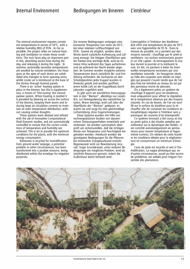
Internal Environment
The internal environment requires consist-ent temperatures in excess of 50ºC, with arelative humidity (RH) of 95%. As far aspossible, the project relies on natural heat-ing and ventilation to create these condi-tions. The rock faces play an important partin this, absorbing excess heat during theday, and releasing it during the night. Insummer, potentially excessive temperaturesare avoided by natural ventilation; the hexa-gons at the apex of each dome are subdi-vided into triangles to form opening vents,whilst cooler air is introduced at the base ofthe domes through louvred panels.
There is an ‘active’ heating system inplace in the biomes, but this is supplemen-tary: a means of ‘fine-tuning’ the naturalpassive system. When heating is needed itis provided by blowing air across the surfaceof the biomes, keeping them warm and in-ducing large air circulation currents to main-tain an even temperature distribution, with-out causing undue draughts.
These systems were devised and refinedwith the aid of innovative ComputationalFluid Dynamic studies, and are automaticallycontrolled to ensure that the correct condi-tions of temperature and humidity areachieved. This is set to provide the optimumconditions for the plants, with the minimumenergy consumption.
Rainwater is recycled for humidification.Even ground water seepage, a potentialproblem in other circumstances, has beentransformed into a positive resource, beingdistributed within the envelope for irrigationpurposes.
Die inneren Bedingungen verlangen einekonstante Temperatur von mehr als 50°C,bei einer relativen Luftfeuchtigkeit von95%. Soweit als möglich, werden dieseWerte durch natürliche Aufheizung und Lüf-tung erzeugt. Die felsigen Oberflächen spie-len hierbei eine wichtige Rolle, weil sie ex-treme Hitze während des Tages aufnehmenund sie während der Nacht wieder abge-ben. Im Sommer werden mögliche extremeTemperaturen durch natürliche Be- und Ent-lüftung verhindert: die Sechsecke an denScheitelpunkten jeder Kuppel wurden inDreiecke geteilt und werden geöffnet,wenn kühle Luft an der Kuppelbasis durchJalousien zugeführt wird.
Es gibt auch ein künstliches Heizungssys-tem in den “Biomes”, allerdings nur zusätz-lich, zur Feinregulierung des natürlichen Sy-stems. Wenn benötigt, wird Luft über dieOberfläche der “Biomes” geblasen, er-wärmt sie und sorgt für eine gleichmäßigeLuftverteilung ohne Zugerscheinungen.
Diese Systeme wurden mit Hilfe vonrechnergestützten Studien von dynami-schem Strömungsverhalten entwickelt undverbessert. Sie werden automatisch über-prüft um sicherzustellen, daß die richtigenWerte von Temperatur und Feuchtigkeit ein-gehalten werden. Hierdurch werden diegünstigsten Bedingungen für die Pflanzenbei minimalem Energieaufwand erreicht.Regenwasser wird zur Bewässerung recy-celt. Sogar Grundwasser, unter anderen Be-dingungen ein mögliches Problem, wird alsnützliche Ressource genutzt, indem dieAußenhaut damit berieselt wird.
Bedingungen im Inneren
27
Aru
p /
And
y Pa
ssin
gham
L’atmosphère à l’intérieur des biodômesdoit offrir une température de plus de 50°Cavec une hygrométrie de 95 %. Dans lamesure du possible, on y parvient par desmoyens naturels : chauffage par le soleil etventilation. Les rochers environnants jouentici un rôle capital : ils emmagasinent la cha-leur durant la journée et la restituent lanuit. En été, on parvient à éviter les éven-tuelles températures excessives par uneventilation naturelle : les hexagones situésau faîte des coupoles sont divisés en trian-gles qui peuvent s’ouvrir tandis que de l’airplus frais est introduit au niveau du sol pardes panneaux munis de jalousies.
On a également prévu un système dechauffage d’appoint pour les biodômes,mais uniquement pour affiner la régulationde la température obtenue par des moyensnaturels. En cas de besoin, de l’air est souf-flé sur la surface du biodôme pour la ré-chauffer afin de conserver les conditions at-mosphériques requises à l’intérieur sans yprovoquer de courants d’air intempestifs.
Ce système innovant a été conçu et misau point grâce à des études assistées parordinateur sur la dynamique des fluides ; ilest contrôlé automatiquement en perma-nence pour assurer température et hygro-métrie corrects. On obtient de cette maniè-re les conditions idéales pour la végétationtout en consommant un minimum d’éner-gie.
L’eau de pluie est recyclée et sert à l’hu-midification. La nappe phréatique qui, end’autres circonstances, aurait pu être sourcede problèmes, est utilisée pour irriguer l’en-semble des plantations.
L’intérieur
12 Architecture Steel Stahl Acier 14
Maintenance
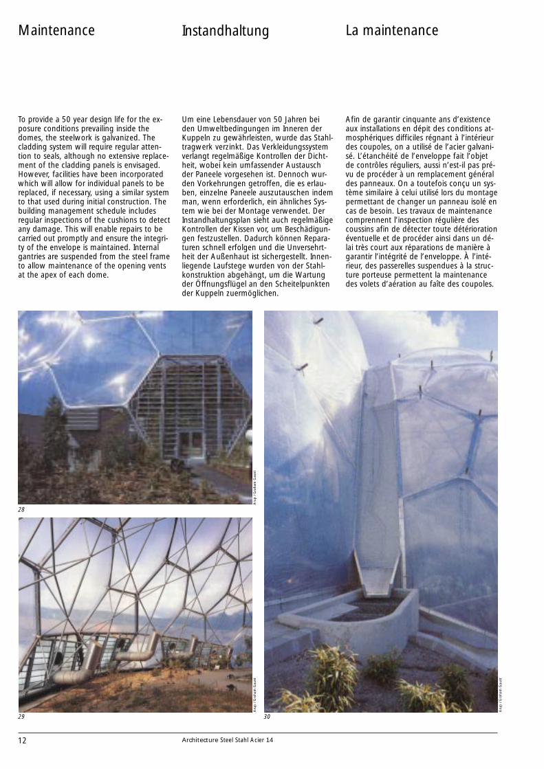
To provide a 50 year design life for the ex-posure conditions prevailing inside thedomes, the steelwork is galvanized. Thecladding system will require regular atten-tion to seals, although no extensive replace-ment of the cladding panels is envisaged.However, facilities have been incorporatedwhich will allow for individual panels to bereplaced, if necessary, using a similar systemto that used during initial construction. Thebuilding management schedule includesregular inspections of the cushions to detectany damage. This will enable repairs to becarried out promptly and ensure the integri-ty of the envelope is maintained. Internalgantries are suspended from the steel frameto allow maintenance of the opening ventsat the apex of each dome.
Um eine Lebensdauer von 50 Jahren beiden Umweltbedingungen im Inneren derKuppeln zu gewährleisten, wurde das Stahl-tragwerk verzinkt. Das Verkleidungssystemverlangt regelmäßige Kontrollen der Dicht-heit, wobei kein umfassender Austauschder Paneele vorgesehen ist. Dennoch wur-den Vorkehrungen getroffen, die es erlau-ben, einzelne Paneele auszutauschen indemman, wenn erforderlich, ein ähnliches Sys-tem wie bei der Montage verwendet. DerInstandhaltungsplan sieht auch regelmäßigeKontrollen der Kissen vor, um Beschädigun-gen festzustellen. Dadurch können Repara-turen schnell erfolgen und die Unversehrt-heit der Außenhaut ist sichergestellt. Innen-liegende Laufstege wurden von der Stahl-konstruktion abgehängt, um die Wartungder Öffnungsflügel an den Scheitelpunktender Kuppeln zuermöglichen.
Instandhaltung
29
28
30
Aru
p /
Gra
ham
Gau
ntA
rup
/ G
raha
m G
aunt
Aru
p /
Gra
ham
Gau
nt
Afin de garantir cinquante ans d’existenceaux installations en dépit des conditions at-mosphériques difficiles régnant à l’intérieurdes coupoles, on a utilisé de l’acier galvani-sé. L’étanchéité de l’enveloppe fait l’objetde contrôles réguliers, aussi n’est-il pas pré-vu de procéder à un remplacement généraldes panneaux. On a toutefois conçu un sys-tème similaire à celui utilisé lors du montagepermettant de changer un panneau isolé encas de besoin. Les travaux de maintenancecomprennent l’inspection régulière descoussins afin de détecter toute détériorationéventuelle et de procéder ainsi dans un dé-lai très court aux réparations de manière àgarantir l’intégrité de l’enveloppe. À l’inté-rieur, des passerelles suspendues à la struc-ture porteuse permettent la maintenancedes volets d’aération au faîte des coupoles.
La maintenance

13Architecture Steel Stahl Acier 14
The Link
The Biome Link primarily functions as theentry to the biome complex, and has thusbeen designed with the ease of visitormovement in mind. It is essentially twostructures within one: a front-facing publicfacility, incorporating a raised walkway intothe biomes, and a two-storey service areato the rear. The roof plane is ‘warped’ atboth ends, and its profiled steel deckingsupports a green roof system that allowsthe Biome Link seemingly to blend into the‘cool temperate zone’ of its surrounding en-vironment. Access is by way of a path thatwinds down through this zone from the Vis-itors’ Centre.
Der Verbindungsbau dient in erster Linie alsEingang in den “Biome-Komplex” und wur-de in Hinblick auf die Besucherströme ent-worfen. Er besteht hauptsächlich aus zweiBaukörpern, einem vorderen Bauteil für dasPublikum mit einem aufgeständerten Fuß-weg zu den “Biomes” und einem Service-gebäude an der Rückseite. Die Dachebeneist an beiden Enden gekrümmt und die Dek-kung aus Stahlprofilblechen trägt ein be-grüntes Dach, das den Verbindungsbau op-tisch in die kühl temperierte Umgebungübergehen läßt. Den Zugang bildet ein ge-wundener Pfad, der vom Besucherzentrumdurch diese Zone führt.
Der Verbindungsbau
31
32
28 Maintenanceentrance
29 Vents and heating
30 Collecting rainwaterfor humidification
31 Exterior view of theLink
32 General view of theLink interior
Aru
p /
Gra
ham
Gau
ntA
rup
/ G
raha
m G
aunt
28 Wartungsflügel
29 Heizung und Lüftung
30 Sammlung desRegenwassers fürdie Besprengung
31 Außenansicht desVerbindungsbaues
32 Innenansicht desVerbindungsbaues
Le bâtiment de liaison sert tout d’abordd’entrée aux deux biodômes ; il a été dessi-né dans le but d’accueillir la foule des visi-teurs. Il est divisé en deux parties : une enfaçade pour le public avec un passage suré-levé conduisant aux biodômes et une autre,de service, à l’arrière. Soutenue par despoutrelles d’acier et incurvée à ses deux ex-trémités, la toiture est entièrement verteafin de ménager une transition entre lesbiodômes et la “ zone tempérée ” de l’envi-ronnement. On y arrive par un sentier quiserpente depuis le centre des visiteurs.
Le bâtiment de liaison
28 Entrée de service
29 Bouches d’aération etde chauffage
30 Collecteur d’eau depluie pourl’humidification
31 Vue du bâtiment deliaison
32 Vue intérieure dubâtiment de liaison

14 Architecture Steel Stahl Acier 14
The Visitors Centre
Built on the apex of the site, the Visitors’Centre is primarily an educational facility,with multimedia exhibits serving to intro-duce the aims and objectives of the project.The structure itself is equally informative, interms of what it reveals about the designethos of Eden as a whole. Dramaticallycurving to complement the contours of thequarry, it consists of two single-storey build-ings linked by a partially covered courtyard.While the smaller (service) building nestlesinto the quarry, the main building thrustsoutwards, offering a panoramic view of thebiomes.
The main building is steel framed. To thesouth, the roof surface (a steel deck cappedwith aluminium) forms an overhang thatshelters a rammed earth elevation. The useof rammed earth walling as a constructiontechnique is local to Cornwall. It is also verymuch in keeping with The Eden Project’semphasis on recycling. The material used isthe excess from excavation work carried outelsewhere on the site, geologically identi-fied as containing the required range of par-ticle sizes.
Errichtet am höchsten Punkt des Geländes,dient das Besucherzentrum in erster LinieUnterrichtszwecken. Multimedia-Vorführun-gen sollen in die Ziele und Absichten desProjekts einführen. Die bauliche Struktur istebenfalls informativ, weil sie die Entwurfs-philosophie des gesamten Eden-Projektsdeutlich macht. Aufregend geschwungen,den Konturen der Grube folgend, bestehtdas Besucherzentrum aus zwei eingeschos-sigen Baukörpern, mit einem dazwischenlie-genden, teilüberdachten Innenhof. Wäh-rend das kleinere (Service-) Gebäude in derGrube liegt, schiebt sich das Hauptgebäudenach außen und bietet einen Panoramablickauf die “Biomes”.Das Tragwerk des Hauptgebäudes ist eineStahlkonstruktion. Südlich bildet das Dach(ein Stahlblechdach mit Aluminiumdeckung)eine Auskragung, die einen aufgeschütte-ten Erdwall schützt. Diese Erdwälle sindeine in Cornwall traditionelle Technik. Siepassen auch in die, dem Eden-Projekt eige-nen Vorliebe für Recycling. Das verwendeteMaterial stammt aus Aushubarbeiten imGelände und wurde geologisch auf die ge-eigneten Korngrößen untersucht.
Das Besucherzentrum
33
34
33 Section of theVisitors´ Centre
34 The Visitors´ Centre
Pete
r C
ook
33 Schnitt durch dasBesucherzentrum
34 Besucherzentrum
Érigé sur le point le plus élevé du site, lecentre des visiteurs a une fonction essentiel-lement éducative. Il abrite des présentationsmultimédias qui renseignent le visiteur surles motivations et les objectifs du projet. Lastructure de ce bâtiment remplit égalementune fonction d’information en permettantde comprendre la philosophie de l’ensembledu projet Eden. Avec ses lignes élancéesépousant le profil de la carrière, le centre secompose de deux bâtiments d’un seul ni-veau reliés par une cour intérieure partielle-ment couverte. Alors que le plus petit (ré-servé au service) occupe une dépression, leplus grand se hisse en avant et offre unevue panoramique sur les biodômes.
La structure porteuse du bâtiment princi-pal est en acier. Au sud, la toiture (en acierrecouvert d’aluminium) en porte-à-faux estprotégée par un remblai de terre. Cette le-vée de terre constituant un rempart devantune construction obéit à une tradition loca-le. Mais elle correspond aussi à la motiva-tion profonde sous-tendue par le projet derecycler. Le matériau utilisé provient des tra-vaux d’excavation de la carrière et a étéchoisi, pour l’adéquation de sa granulomé-trie.
Le centre des visiteurs
33 Coupe du centre desvisiteurs
34 Le centre des visiteurs
15Architecture Steel Stahl Acier 14
The Eden Experience
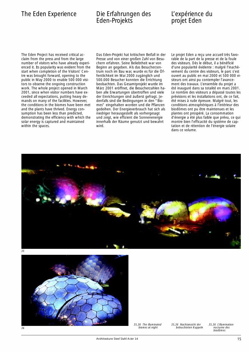
The Eden Project has received critical ac-claim from the press and from the largenumber of visitors who have already experi-enced it. Its popularity was evident from thestart when completion of the Visitors’ Cen-tre was brought forward, opening to thepublic in May 2000 to enable 500 000 visi-tors to observe the ongoing constructionwork. The whole project opened in March2001, since when visitor numbers have ex-ceeded all expectations, putting heavy de-mands on many of the facilities. However,the conditions in the biomes have been metand the plants have thrived. Energy con-sumption has been less than predicted,demonstrating the efficiency with which thesolar energy is captured and maintainedwithin the spaces.
Das Eden-Projekt hat kritischen Beifall in derPresse und von einer großen Zahl von Besu-chern erfahren. Seine Beliebtheit war vonBeginn an gegeben. Als das Besucherzen-trum noch im Bau war, wurde es für die Öf-fentlichkeit im Mai 2000 zugänglich und500.000 Besucher konnten die Errichtungbeobachten. Das Gesamtprojekt wurde imMärz 2001 eröffnet, die Besucherzahlen ha-ben alle Erwartungen übertroffen und vieleder Einrichtungen sind äußerst gefragt. Je-denfalls sind die Bedingungen in den “Bio-mes” eingehalten worden und die Pflanzengedeihen. Der Energieverbrauch hat sich alsniedriger herausgestellt als vorhergesagtund zeigt, wie effizient die Sonnenenergieinnerhalb der Räume genutzt und bewahrtwird.
Die Erfahrungen desEden-Projekts
35
3635,36 The illuminated
biomes at night35,36 Nachtansicht der
beleuchteten Kuppeln
Le projet Eden a reçu une accueil très favo-rable de la part de la presse et de la fouledes visiteurs. Dès le début, il a bénéficiéd’une popularité évidente : malgré l’inachè-vement du centre des visiteurs, le parc s’estouvert au public en mai 2000 et 500 000 vi-siteurs ont ainsi pu contempler l’avance-ment des travaux. L’ensemble du projet aété inauguré dans sa totalité en mars 2001.Le nombre des visiteurs a dépassé toutes lesprévisions et les installations ont, de ce fait,été mises à rude épreuve. Malgré tout, lesconditions atmosphériques à l’intérieur desbiodômes ont pu être maintenues et lesplantes ont prospéré. La consommationd’énergie a été plus faible que prévu, ce quimontre bien l’efficacité du système de cap-tation et de rétention de l’énergie solairedans ce volume.
L’expérience duprojet Eden
35,36 L’illuminationnocturne desbiodômes
16 Architecture Steel Stahl Acier 14
Facts and Figure
Area of site: 50haArea of pit: 15haProject value: £86m
Humid Tropics BiomeArea: 1,5haMaximum height: 55mMaximum width: 110mLength: 240m
Warm Temperate BiomeArea: 0,65haMaximum height: 35mMaximum width: 65mLength: 135m
Grundfläche des Geländes: 50 haGrundfläche der Grube: 15 haBaukosten: 86 Mill. £
Tropisches FeuchtbiomeFläche: 1,5 haMax. Höhe: 55 mMax. Spannweite: 110 mLänge: 240 m
Warm-gemäßigtes BiomeFläche: 0,65 haMax. Höhe: 35 mMax. Spannweite: 65 mLänge: 135 m
Zahlen und Daten
37
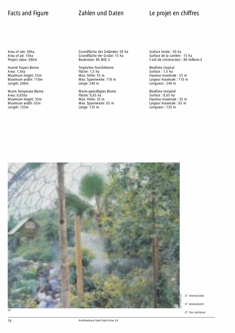
37 Internal view
37 Innenansicht
37 Vue intérieure
Aru
p /
Gra
ham
Gau
nt
Surface totale : 50 haSurface de la carrière : 15 haCoût de construction : 86 millions £
Biodôme tropical Surface : 1,5 haHauteur maximale : 55 mLargeur maximale : 110 mLongueur : 240 m
Biodôme tempéréSurface : 0,65 haHauteur maximale : 35 mLargeur maximale : 65 mLongueur : 135 m
Le projet en chiffres

Architecture Steel Stahl Acier 14
European SteelInformationSources
Architecture Steel Stahl Acier is intended to providearchitects with a series of case studies of notablebuildings built with steel.
EditorECCS-European Convention for ConstructionalSteelwork
The publication is managed by ECCS CommitteeAC9: Architectural Aspects of Steel Construction
Original textRoger Plank
TranslationsPeter Cziffer, GermanCedam, French
DrawingsNicholas Grimshaw & PartnersVector Special Projects (23)
Design and lay outEsko Miettinen, architect
Printed byLibris 8/2003
AUSTRIA
ÖsterreichischerStahlbauverband *Wiedner Hauptstraße 63,A-1045 Wien
Tel: +43 1 503 9474Fax: +43 1 503 9474 227
BELGIUM
Agoria *Diamant BuildingBld A. Reyers 80, B-1030 Brussels
Tel: +32 2 706 7962Fax: +32 2 706 7966
Centre Information AcierStaalinfocentrum (CIA)Chaussée de Zellik 12, 1082 BruxellesZelliksesteenweg 12, B-1082 Brussels
Tel: +32 2 509 1504Fax: +32 2 511 1281
CROATIA
Hrvatska Zajednica zaMetalne Konstrukcije *Janka Rakuse 1, HR-10 000 Zagreb
Tel: +385 1 614 4746Fax: +385 1 614 4744
CZECH REPUBLIC
Czech Constructional Steel-work Association *Krokova 4, 700 30 Ostrava-Zaboeh
Tel: +420 69 678 2600Fax: +420 69 357 730
DENMARK
Dansk Stålinstitut *Kochsgade 31, DK-5100 Odense C
Tel: +45 66 13 08 88Fax: +45 65 91 87 89
ESTONIA
EestiTeraskonstruktsiooniühing *Ehitajate tee 5, 19086 Tallinn
Tel: +372 620 2410Fax: +372 620 2405
FINLAND
Federation of Finnish Metal,Engineering and Electro-technical Industries *Eteläranta 10, FIN-00130 Helsinki
Tel: +358 9 192 31Fax: +358 9 624 462
Finnish ConstructionalSteelwork AssociationEteläranta 10, FIN-00130 Helsinki
Tel: +358 9 172 841Fax: +358 9 1728 4444
FRANCE
Syndicat de la ConstructionMétallique de France *20, rue Jean-Jaurès,F- 92807 Puteaux Cedex
Tel: +33 1 47 74 66 15Fax: +33 1 40 90 08 60
Centre Technique Industrielde la Construction Métallique(CTICM)Domaine de Saint-Paul, BP 64,F-78470 Saint-Rémy-les-Chevreuse
Tel: +33 1 30 85 20 00Fax: +33 1 30 52 75 38
Office Technique pourl’Utilisation de l’Acier (OTUA)13 Cours ValmyF - 92070 Paris La Défense
Tel: +33 1 41 67 04 02Fax: +33 1 41 25 55 70
GERMANY
Deutscher Stahlbau-VerbandDSTV *Sohnstraße 65, D-40237 Düsseldorf
Tel: +49 211 6707 800Fax: +49 211 6707 820
Bauen mit Stahl e.V.Sohnstraße 65, D-40237 Düsseldorf
Tel: +49 211 6707 828Fax: +49 211 6707 829
Stahl-Informations-ZentrumSohnstraße 65, D-40237 Düsseldorf
Tel: +49 211 6707 831Fax: +49 211 6707 344
HUNGARY
Magyarországi Acélszerkezet -Gyártók Szövetsége (Magész) *2400 Dunaújváros, Vasmü tér 1-3,H-2401 Dunaújváros, Pf. 110
Tel: +36 25 583 970, 583 639Fax: +36 25 583 525
ITALY
Associazione fra i Costruttoriin Acciaio Italiani *Viale Abruzzi 66, I-20131 Milano
Tel: +39 02 2951 3413Fax: +39 02 2952 9824
LUXEMBOURG
Arcelor Building andConstruction Support66 rue de LuxembourgL - 4221 Esch-sur-Alzette
Tel: +352 5313 3007Fax: +352 5313 3095
NETHERLANDS
SamenwerkendeNederlandse Staalbouw(SNS) *Boerhaavelaan 40, Postbus 190NL-2700 AD Zoetermeer
Tel: +31 79 353 1265Fax: +31 79 353 1365
Bouwen met StaalStationsplein 45, A4, 194NL - 3013 AK Rotterdam
Tel: +31 10 411 50 70Fax: +31 10 412 12 21
NORWAY
Den Norske Stålgruppen *Postboks 7072-Majorstua,N-0306 Oslo 3
Tel: +47 22 59 01 03Fax: +47 22 59 01 33
PORTUGAL
Associação Portuguesa deConstrução Metálica e Mista(Cmm) *Pálácio de Vila Flor,Av. D. Afonso Henriques,PT- 4810-431Guimarães
Tel: +351 253 415 142Fax: +351 253 415 389
ROMANIA
Asociatia Producatorilor deConstructii Metalice DinRomania (APCMR) *1, Piata Iancu de HunedoaraRO- 2750 Hunedoara
Tel: +40 254 740 200Fax: +40 254 717 650
SLOVENIA
Institut za MetalneKonstrukcije *Mencingerjeva 7, SI-1000 Ljubljana
Tel: +386 61 332 521Fax: +386 61 332 416
SPAIN
Asociación para laConstrucción deEstructuras Metálicas *Plaça de la Unió, 1 Edificio B 1° 2a,ES-08190 Sant Cugat del Vallés
Tel: +34 93 589 3636Fax: +34 93 590 8249
Instituto Tecnico de laEstructura en AceroPol. Industrial de OrdiziaC/Mallutz, Edificio 5,ES-20240 OrdiziaTel: +34 43 88 74 76Fax: +34 43 88 76 22
SWEDEN
Swedish Institute of SteelConstruction *Box 27751, S-115 92 Stockholm
Tel: +46 8 661 0280Fax: +46 8 661 0305
SWITZERLAND
Stahlbau Zentrum Schweiz/Centre Suisse de laConstruction Métallique *Seefeldstraße 25, CH-8034 Zürich
Tel: +41 1 261 8980Fax: +41 1 262 0962
TURKEY
Turkish Constructional Steel-work Association (TUCSA) *Kisikli Mah.Bulgurlu, Cad.18Uskudar, 81190 Istanbul
Tel: +90 216 325 7304Fax: +90 216 325 7184
UNITED KINGDOM
British ConstructionalSteelwork Association *4 Whitehall Court - Westminster,London SW1A 2ES
Tel: +44 20 7839 8566Fax: +44 20 7976 1634
Corus Construction& IndustrialFrodingham HouseBrigg Road, ScunthorpeNorth Lincolnshire DN16 1BP
Tel: +44 1724 405 060Fax: +44 1724 404 224
The Steel ConstructionInstituteSilwood Park, Ascot, Berks, SL5 7QN
Tel: +44 1344 23345Fax: +44 1344 22944
ECCS General SecretariatAvenue des Ombrages 32/20,B-1200 Brussels
Tel: +32 2 762 0429Fax: +32 2 762 0935
* ECCS member associations

Architecture Steel Stahl Acier 14
ArchitectureSteel Stahl Acier
The Eden Project in Cornwall, UK, is thelargest plant enclosure in the world,recreating tropical and warm temperatehabitats. The primary design objective wasto create the correct environment forgrowth using minimum water and energy.The key issues were also orientation,natural lighting and heating, and maximumrecycling of water.
The space frame form of the domesminimised the size and number ofstructural elements, which are made of steeltubes bolted together by steel nodes. Therequired high transparency of the envelopewas achieved using ETFE (Ethylene TetraFluoro Ethylene) foil, a thin, lightweightmaterial and therefore capable of coveringwide spans supported by the most minimalof structures.
Das Eden-Projekt in Cornwall ist das größteGewächshaus der Welt mit tropischen undwarm-temperierten Zonen. Dasvordringlichste Entwurfsziel war, eineperfekte Umgebung für das Wachstum beiMinimalverbräuchen von Wasser undEnergie zu schaffen. Wesentliche Kriterienwaren ebenso Ausrichtung, natürlicheBelichtung und Beheizung, sowiegrößtmögliches Recycling von Wasser.
Das Raumtragwerk der Biomes reduziertGröße und Zahl der Stukturelemente ausStahlrohren, die mittels stählernenKnotenelementen verbunden sind. Diegeforderte hohe Transparenz derAußenhaut wurde durch die Verwendungeiner ETFE (Ethylen Tetra Fluor Ethylen)-Folie,eines dünnen und leichten Materials,erreicht. So konnten große Spannweitenbei sparsamster Tragwerksdimensionierungüberdeckt werden.
S. B
urt /
Ape
x
Le projet Eden en Cornouailles (Royaume-Uni) est le plus grand jardin botanique dumonde ; il recrée deux écosystèmesdifférents, l’un tropical humide et l’autretempéré. Le premier objectif était de créerun environnement convenant à lacroissance des plantes en utilisant unminimum d’eau et d’énergie. Les pointsessentiels ont donc été l’orientation desbâtiments, leurs éclairage et chauffagenaturels et le recyclage de l’eau.
La forme en coupoles a permis deréduire la taille et le nombre des structuresporteuses ; celles-ci sont composées detubes d’acier assemblés par des nœudségalement en acier. On a obtenu le degréde transparence requis pour l’enveloppe enemployant des feuilles en ETFE(ethyltétrafluoro-éthylène), un matériau finet léger, capable de couvrir de grandessurfaces tout en étant d’un coût réduit.