karma user manual - european southern observatory · 2 karma user manual vlt-man-kmo-146606-002 eso...
TRANSCRIPT

EUROPEAN SOUTHERN OBSERVATORY
Organisation Europeene pour des Recherches Astronomiques dans l’Hemisphere AustralEuropaische Organisation fur astronomische Forschung in der sudlichen Hemisphare
ESO - European Southern ObservatoryKarl-Schwarzschild Str. 2, D-85748 Garching bei Munchen
Very Large Telescope
KMOSKARMA User Manual
Document No. VLT-MAN-KMO-146606-002
Issue 2.4.2
December 17, 2013
Prepared: M. Wegner
Approved: P. Rees
Released: A. Fairley

II KARMA User Manual VLT-MAN-KMO-146606-002
This page was intentionally left blank.

VLT-MAN-KMO-146606-002 KARMA User Manual III
Change Record
Issue1 Date Sections Reason/Remarks
1.0.1 2012-05-30 all Prepared for PAE.1.1 2012-07-11 all Version after end-to-end tests and before PAE meeting.2.0 2013-05-15 all New KARMA release prepared for Science Verification.2.1 2013-06-21 all Screenshots and example PAF replaced.2.2 2013-08-27 all Version number updated to new KARMA release after some bug fixes.2.3 2013-09-25 all Version number updated to new KARMA release after new check for
tab characters.2.4 2013-12-02 4 Allowed special characters in catalogue comments listed.
3,A Recommendation added where system libraries required for KARMAbuild can be found.
B Guide star entries in M4 example catalogue replaced by positions of2MASS-associated optical sources with R magnitudes.
3 Mechanism for enabling/disabling of single arms described. Bash men-tioned as a build precondition.
all Screenshots and example PAF replaced.2.4.2 2013-12-17 8 Remark with respect to locked/disabled arms added.
1The version number of this manual is kept consistent with the version number of the actual KARMA release.

IV KARMA User Manual VLT-MAN-KMO-146606-002
This page was intentionally left blank.

VLT-MAN-KMO-146606-002 KARMA User Manual V
Contents
1 Introduction 1
1.1 Audience, prerequisites and organisation of this manual . . . . . . . . . . . . . . . . . 1
1.2 Abbreviations and acronyms . . . . . . . . . . . . . . . . . . . . . . . . . . . . . . . . . 1
1.3 Stylistic conventions . . . . . . . . . . . . . . . . . . . . . . . . . . . . . . . . . . . . . 2
1.4 Reference documents . . . . . . . . . . . . . . . . . . . . . . . . . . . . . . . . . . . . . 2
1.5 Web links and contact information . . . . . . . . . . . . . . . . . . . . . . . . . . . . . 3
1.6 Acknowledgements . . . . . . . . . . . . . . . . . . . . . . . . . . . . . . . . . . . . . . 3
2 An overview of KARMA 4
2.1 The role of KARMA within the VLT Data Flow System . . . . . . . . . . . . . . . . . 4
2.2 What you need . . . . . . . . . . . . . . . . . . . . . . . . . . . . . . . . . . . . . . . . 5
2.3 What you actually do with KARMA . . . . . . . . . . . . . . . . . . . . . . . . . . . . 5
2.4 What you get . . . . . . . . . . . . . . . . . . . . . . . . . . . . . . . . . . . . . . . . . 7
3 Getting started 8
3.1 Obtaining the KARMA package . . . . . . . . . . . . . . . . . . . . . . . . . . . . . . 8
3.2 Building and installing KARMA from the source distribution . . . . . . . . . . . . . . 8
3.3 Installing a KARMA binary distribution . . . . . . . . . . . . . . . . . . . . . . . . . . 10
3.4 Starting KARMA . . . . . . . . . . . . . . . . . . . . . . . . . . . . . . . . . . . . . . . 10
3.5 Adapting the graphical user interface . . . . . . . . . . . . . . . . . . . . . . . . . . . . 11
3.6 Disabling of single pick-off arms . . . . . . . . . . . . . . . . . . . . . . . . . . . . . . . 12
3.7 The example files . . . . . . . . . . . . . . . . . . . . . . . . . . . . . . . . . . . . . . . 13
4 Step 1: Prepare and load catalogue 14
5 Step 2: Load image 19
6 Step 3: Identify bright objects 22
7 Step 4: Choose observing mode 24
7.1 Nod to Sky mode . . . . . . . . . . . . . . . . . . . . . . . . . . . . . . . . . . . . . . . 24
7.2 Stare mode . . . . . . . . . . . . . . . . . . . . . . . . . . . . . . . . . . . . . . . . . . 25
7.3 Mosaic mode . . . . . . . . . . . . . . . . . . . . . . . . . . . . . . . . . . . . . . . . . 25
7.4 Switching between the modes . . . . . . . . . . . . . . . . . . . . . . . . . . . . . . . . 27
8 Step 5: Define arm configuration for science observation 28
8.1 Fixing telescope position and instrument rotator angle . . . . . . . . . . . . . . . . . . 29
8.2 Allocating the pick-off arms . . . . . . . . . . . . . . . . . . . . . . . . . . . . . . . . . 29
8.2.1 Hungarian Algorithm . . . . . . . . . . . . . . . . . . . . . . . . . . . . . . . . 30
8.2.2 Stable Marriage Algorithm . . . . . . . . . . . . . . . . . . . . . . . . . . . . . 32
8.2.3 Manual Allocation . . . . . . . . . . . . . . . . . . . . . . . . . . . . . . . . . . 33
8.2.4 Allocation in Mosaic Mode . . . . . . . . . . . . . . . . . . . . . . . . . . . . . 34
8.3 Finding a suitable sky background position . . . . . . . . . . . . . . . . . . . . . . . . 34
8.4 Creating hardcopies and finding charts . . . . . . . . . . . . . . . . . . . . . . . . . . . 34
9 Step 6: Define arm configuration for acquisition 38
9.1 Acquisition from science targets . . . . . . . . . . . . . . . . . . . . . . . . . . . . . . . 38
9.2 Acquisition from reference targets . . . . . . . . . . . . . . . . . . . . . . . . . . . . . . 39
10 Step 7: Select telescope guide stars 41

VI KARMA User Manual VLT-MAN-KMO-146606-002
11 Step 8: Save configuration (PAF) file 44
12 It’s not over until it’s over 46
A Frequently asked questions 48
B Example catalogue 51
C Example PAF file 54
VLT-MAN-KMO-146606-002 KARMA User Manual 1
1 Introduction
Welcome. The document you just start reading describes how to use KARMA. KARMA – the KMOSArm Allocator – is a stand-alone software tool that is based on the ESO Real Time Display (RTD)package. It supports you in preparing observations with the multi-object integral field spectrometerKMOS at the Very Large Telescope. This manual attempts to assist you in this process as good aspossible. Good luck!
1.1 Audience, prerequisites and organisation of this manual
Most probably you are an astronomer who has been granted observing time with KMOS and whonow aims to configure the instrument for an observation as profitable as possible. Or maybe, you area member of the VLT operating staff or any other person who just wants to know what this KARMAis all about. Either way, you should already be familiar with the general KMOS concept and thecapabilities of this elaborated instrument. If not, you should read the KMOS User Manual [2] first.It is also assumed that you at least have a clue about the VLT Data Flow System, that you know thepurpose of the P2PP tool and that you are familiar with the concept of Observation Blocks (OBs)and Templates. In case you are not, please skim through the P2PP User Manual [3] and the KMOSPhase 2 web pages (see section 1.5) before you continue reading this document. A deeper knowledgeof RTD (or of the probably better known RTD extension Skycat), which the KARMA tool is basedon, however, is helpful but not really required as the RTD handling can be understood more or lessintuitively. Nevertheless, a look into the RTD User Manual [1] isn’t completely senseless. You find itonline at http://archive.eso.org/skycat/docs/rtd.
The plan for the following sections is as follows: To begin with, chapter 2 gives an overview ofKARMA, its purpose, philosophy, and role within the VLT Data Flow System. Section 3 then explainshow to obtain, install and start the KARMA package on your computer as well as it helps you toexplore the main features of the Graphical User Interface (GUI). Having accomplished this, sections4 to 11 shall guide you through the several steps of a typical KARMA session in full detail along arunning example. Section 12 eventually shows the different possibilities to resume a KARMA sessionin case it was interrupted before for whatever reason. A list of FAQs can be found in the appendix,which also includes an input catalogue example and a typical KARMA target setup file in the ESOPAF format (in short: “PAF file”) as it is created by KARMA.
To make the most of this manual, you should read it in a sequential way, section by section. Inparticular, sections 4 to 11 all build upon each other, and in each step the running example will bedeveloped a little bit further. Therefore it will be useful to have a running KARMA installation athand where you can try out the suggested interactions immediately.
Once you have finished the guided tour through KARMA, you have then not only prepared aKARMA example output file, which – at least in principle – could be attached to a realistic ObservationBlock later on. Much more important: You will hopefully be able to prepare your own observationsand to evaluate the capabililties and limitations of KARMA. This is the intention of this document,which is predominantly aimed at users and not at maintenance staff. In case you belong to the latter,see also the complementary KARMA Programming and Maintenance Manual [4].
1.2 Abbreviations and acronyms
Not surprisingly for a technical manual, throughout the text a number of acronyms and abbreviationsappear:
2MASS Two Micron All Sky SurveyASCII American Standard Code for Information InterchangeDec Declination

2 KARMA User Manual VLT-MAN-KMO-146606-002
ESO European Southern ObservatoryFAQ Frequently Asked Question(s)FIMS FORS Instrument Mask SimulatorFITS Flexible Image Transport SystemFoV Field of ViewGNU GNU is Not UnixGUI Graphical User InterfaceHTML HyperText Markup LanguageIFU Integral Field UnitJPEG Joint Photographic Experts GroupKARMA KMOS Arm AllocatorKMOS K-band Multi-Object SpectrometerOB Observation BlockP2PP Phase 2 Proposal PreparationPAF Parameter FilePI Principal InvestigatorRA Right AscensionRTD Real Time DisplayTBD To Be DefinedUSM Universitatssternwarte Munchen (University Observatory Munich)VMMPS VIMOS Mask Preparation SoftwareVLT Very Large TelescopeWCS World Coordinate SystemXML Extensible Markup Language
1.3 Stylistic conventions
In order to highlight certain words, sentences or paragraphs, this manual uses the following typo-graphical conventions:
italic : To emphasise something.
monospace : For examples, in particular for input you are advised to type.
<replace> : Denotes something to be substituted with actual content.
link : Internal or external links (either references to sections or figures and email addresses orURLs, respectively) are coloured blue.�� ��Button : For GUI buttons to press.
Menu : For menu items to select. If more than one of these items appear in a sequence then itis suggested to select them one after the other.
�Tab A : For tabs in GUI dialogues.
sans-serif : For all other GUI labels referred to within the running text.
1.4 Reference documents
Although this manual attempts to be self-contained as far as possible, occassionally it is necessaryto refer to one of the following documents, papers, and books, where additional or complementaryinformation can be found:

VLT-MAN-KMO-146606-002 KARMA User Manual 3
[1] VLT-MAN-ESO-17240-0866: RTD User Manual.http://archive.eso.org/skycat/docs/rtd
[2] VLT-MAN-KMO-146603-001: KMOS User Manual. See also link in subsection 1.5.
[3] VLT-MAN-ESO-19200-5167: P2PP User Manual. See also link in subsection 1.5.
[4] VLT-MAN-KMO-146606-003: KARMA Programming and Maintenance Manual.
[5] Kuhn, H. W.: The Hungarian Method for the assignment problem, Naval Research LogisticsQuarterly 2 (1955), 83
[6] Gale, D., Shapley, L. S.: College admissions and the stability of marriage, American Mathe-matical Monthly 69 (1962), 998
1.5 Web links and contact information
Additional information can be found at www.eso.org on the following pages:
KMOS instrument web page:
http://www.eso.org/sci/facilities/paranal/instruments/kmos/index.html
KMOS User Manual and KARMA User Manual:
http://www.eso.org/sci/facilities/paranal/instruments/kmos/doc/index.html
KMOS Phase 2 web pages:
http://www.eso.org/sci/observing/phase2/SMGuidelines.KMOS.html
P2PP web page:
http://www.eso.org/sci/observing/phase2/P2PP3.html
KARMA web page:
http://www.eso.org/sci/observing/phase2/SMGuidelines/KARMA.html
In case of specific questions related to KARMA and its use together with P2PP please contact theESO User Support Department via this email address: [email protected] .
1.6 Acknowledgements
The initial KARMA version was written by Michael Wegner at Universitatssternwarte Munchen, whohereby takes the full responsibility for all possibly arising deficiencies, shortcomings, and bugs. Theauthor also begs your forbearance if this manual should exhibit any deficits in information, style, orlanguage. Suggestions for improvement are always welcome: All user questions, remarks, and reportsabout KARMA should go to [email protected] .
Regardless of that, we would like to thank Alessandra Beifiori, Ralf Bender, Peter Biereichel,Nicolas Bouche, Michele Cirasuolo, Ric Davies, Niv Drory, Peter Erwin, Maximilian Fabricius, MichaelHilker, Carlo Izzo, Mario Kiekebusch, Markus Kissler-Patig, Johannes Koppenhofer, Jaron Kurk,Stephane Marteau, Joseph Mohr, Bernard Muschielok, Luca Pasquini, Dan Popovic, Suzanne Ramsay,Myriam Rodrigues, Roberto Saglia, Ivo Saviane, Jorg Schlichter, Linda Schmidtobreick, Alex Segovia,Stella Seitz, Ray Sharples, Lowell Tacconi-Garman, David Wilman, and Emily Wisnioski for helpfulsuggestions and discussions.
Thanks also to Claus Gossl and Josef Richter for the provision of their Mac computers during thedevelopment phase.
Finally, the 2MASS catalogue query feature of KARMA makes use of the NASA/IPAC InfraredScience Archive, which is operated by the Jet Propulsion Laboratory, California Institute of Technol-ogy, under contract with the National Aeronautics and Space Administration.

4 KARMA User Manual VLT-MAN-KMO-146606-002
2 An overview of KARMA
2.1 The role of KARMA within the VLT Data Flow System
As for any other VLT instrument, you have to prepare KMOS observations in advance, therebyfollowing the general concept of the VLT Data Flow System. Figure 1 shows the main steps in thechain of tasks from the initial observation idea until the final publication of the scientific resultsobtained from the reduced data.
Observation with KMOSPhase 1
proposal prep.Phase 2
observing preparationProgramexecution
Post-observation
Observer’s
home
ESO
Garching
VLT
/Paranal
Scientificobjective
Outstandingpaper
Apply forobserving
time
Phase 1proposal
Preparecatalogue
KARMAcatalogue
Allocatearms
PAF file(s)
PrepareObservationBlock(s)
Observationblock(s)
Executedaytime
calibrations
ExecuteOB(s)
RawFITS frames
Reducedata
Science dataproduct
Doscience
Figure 1: Main steps of a typical KMOS observation. The highlighted steps are covered by this
manual.
After having successfully applied for KMOS time, you must organise your planned observationsinto so-called Observation Blocks (OBs), the smallest possible units containing all the informationnecessary to obtain a single observation. These OBs have to be created by means of the P2PP (Phase2 Observing Preparation) tool at the astromer’s (i.e. your) home workstation and then be sent to anESO repository for later scheduling and execution at VLT in service-mode. Observing in visitor-modedoesn’t change the concept very much: You only have a little bit more time to prepare your OBs –until your visit at Paranal at the latest.
The P2PP software on its part, however, is predominantly intended only for the specification ofsimple parameters like exposure time, filter band, or other settings which essentially are common tothe majority of instruments. If KMOS were a rather simple instrument, this would be quite sufficient.In fact, it is not. Instead, the nature of a multi-object spectrometer in general and the complexityof KMOS in particular require that the standard P2PP tool must be complemented by an additionalpiece of software, which allows a more detailed configuration. Particularly, the optimal allocationof the robotic pick-off arms to their target positions, thereby taking target priorities and severalmechanical and optical constraints into account, can be accomplished only separately by a dedicated
VLT-MAN-KMO-146606-002 KARMA User Manual 5
tool. This is the actual KARMA task. Likewise taking place at your home workstation, a successfulKARMA session delivers an ASCII file in compliance with a proprietary ESO standard, the so-calledPAF format, which in turn can then be fed into the P2PP tool and transferred as an OB attachmentto the ESO repository.
2.2 What you need
For a successful KARMA session you need the following things:
1. A predefined KARMA catalogue in ASCII format. It shall contain the sky coordinates of allyour scientific targets, potential reference and guide stars as well as (optionally) the positionsof particularly bright objects, and a field center, all in the same astrometric system. Section 4explains the different entries and the format of the catalogue as a whole.
2. A sky (FITS) image, preferentially in the infrared, which covers at least the KMOS Field of View(FoV). It should also have valid and correct WCS information in the relevant header keywords.The image is necessary in KARMA only for the determination of a suitable sky backgroundtelescope position. Furthermore, it supports you in getting an impression of what you’re actuallydoing, even if it is completely irrelevant for astrometry. See section 5 for more informationregarding the image.
3. Optional: A network connection. An additional KARMA feature allows to search for additionalbright objects (to be avoided by pick-off arms) via the 2MASS online catalogue. In order to useits web interface, your computer must be connected to the internet. See section 6.
4. This manual, your computer with either a running Linux (32-bit or 64-bit) or Mac OS X2 and, ofcourse, the installed and running KARMA tool itself. How to obtain and build KARMA eitherfrom its sources or how to install one of the precompiled binary distributions is described insection 3.
KARMA is, like other tools supporting the preparation of observations with VLT instruments,based on the ESO RTD software, better known through its Skycat extension. Although some knowl-edge of RTD and/or Skycat is therefore advantageous, it is not really required.
2.3 What you actually do with KARMA
As a precondition for a KARMA session you must have prepared your input catalogue carefully. Theconfiguration task to be performed by KARMA itself then is subdivided into 8 well-defined steps (seefigure 2):
1. After having started a new KARMA session, you load your previously prepared catalogue intoKARMA. KARMA displays the positions of all contained entries in the main window. See section4 for a detailed description.
2. Then you load your sky background image. See section 5. In exceptional cases this step can beskipped, although it is not recommended.
3. Because of undesirable straylight emanating from the metallic surfaces of the pick-off arms, theseshall not be placed at positions of bright sky objects. In addition to the possibly already providedcoordinates of such objects along with the input catalogue, you have the option to identifyadditional objects querying the 2MASS online catalogue. KARMA displays the locations ofthose objects on the image. See section 6.
2At the time of writing no other platform is supported. Particularly, there is no KARMA for Windows or Vista.

6 KARMA User Manual VLT-MAN-KMO-146606-002
KARMA SessionPredefinedcatalogue
Sky image
2MASScatalogue
Finding chart(JPEG)
KARMAsession file(XML)
Configurationfile (PAF)
STARTLoad catalogue
Load sky image
Identify bright objects
Choose observing modeNod to Sky,Stare orMosaic
Define/ModifyScience configurationat (αSCI, δSCI, ϕSCI)
Define/ModifySky configuration
at (αSKY, δSKY, ϕSKY)
[acquisition possiblefrom science config.]
[separate acquisition stepnecessary]
Define/ModifyAcquisition configurationat (αACQ, δACQ, ϕACQ)
Define/ModifySky configuration
at (αSKA, δSKA, ϕSKA)
Select telescope guide stars
Check + save configuration[targets still available] [all targets assigned]
END
Finding chartrequired
Createfinding chart
Session stateshall be stored
SaveKARMA session
Figure 2: The typical sequence of steps in a KARMA session. Finding charts and XML files can be
created optionally at any time.
4. According to the envisaged type of observation, you select the observation mode. See section 7for an explanation of the 3 possible modes Nod to Sky, Stare and Mosaic.
5. This is the main step and the actual KARMA task (section 8).
(a) You fix telescope position and instrument rotator angle at an observation position suitableto allocate as many science targets as possible.
(b) KARMA then allocates pick-off arms to science target positions and presents the assignmentwhich you can either accept or modify manually.
(c) You search a suitable sky background position depending on the selected observation mode.This, by the way, is the only step where the image is presumably indispensable.
(d) Optionally, you can also save a PostScript hardcopy of your pick-off arm configuration or aJPEG finding chart.
6. You define an acquisition configuration (section 9).
(a) You fix telescope position and rotator angle at an acquisition position suitable to allocateas many reference targets as possible.
(b) KARMA allocates pick-off arms for acquisition and presents the assignment, which you againcan either accept or modify manually.
(c) KARMA provides a default sky background position which you can modify.
(d) Again, you have the option to save a hardcopy or a finding chart.
7. You select a number of potential telescope guide stars (section 10).

VLT-MAN-KMO-146606-002 KARMA User Manual 7
8. You save your configuration in ESO proprietary PAF format for further processing with the P2PPtool as described above (see also section 11). Optionally, you save the status of your KARMAsession in an XML file in case you want to interrupt and resume it later on. If not already done,you can save here a JPEG finding chart, too.
Steps 4 through 8 can be repeated as long as there are not assigned targets available in the catalogue.Step 6 will be skipped by KARMA automatically in case there are already science targets bright enoughfor acquisition allocated in step 5. Likewise, for the Mosaic Mode there is no separate acquisition steprequired.
All steps, which are only briefly mentioned here, are desribed in full detail in sections 4 to 11.
2.4 What you get
If you follow the steps above, you will complete your KARMA session with the following things created:
• One or more ASCII file(s) in an ESO-specific proprietary (‘PAF’) format which you can attachto the Observation Block(s) you create with the P2PP tool via the entry ‘KARMA target setupfile’.
• One or more JPEG finding charts that have to be attached to Observation Blocks later on.
• Optional: One or more PostScript files showing your actual arm configuration and correspondingposition information.
• Optional: An XML file which saves the actual state of the KARMA session and allows to resumework on the current configuration at any time.

8 KARMA User Manual VLT-MAN-KMO-146606-002
3 Getting started
3.1 Obtaining the KARMA package
As of 1 March 2013, KARMA can be obtained from the following web page at ESO, providing alwaysthe most recent KARMA version for download:
http://www.eso.org/sci/observing/phase2/SMGuidelines/KARMA.html .
Check there from time to time for new releases. Make sure you have the most recent one before youstart preparing your observation.
3.2 Building and installing KARMA from the source distribution
KARMA is organised and distributed as a collection of source packages, each of which is buildable likea typical GNU Autotools project. KARMA as a whole can be built and installed by a dedicated scriptkarmaBuild, which in turn performs the standard GNU configure, make, make install sequence forall the comprised packages separately. Then it creates a so-called Starpack, a single binary bundlinga custom Tcl interpreter and the KARMA/RTD code, which is finally installed into the destinationdirectory. See figure 3.
KARMA build
karma_src-<version>.tar.gz
KARMA
tar fvxz
tcl 8.4.19tk 8.4.19tcl x8.4itcl 3.3
iwidgets 4.0.1tkimg 1.3
blt 2.4
cfitsio
rtd 2.98
kmmcfgkmclibkmcpan
kmskmspankmsdat
src
mkvfszlib
runtime.vfskarma.vfs
Sample catalogues/images
VLT-MAN-KMO-146606-002
iterative
configure
make
make install
Create Starpack
Installto destination
Figure 3: The KARMA install process. After having unpacked the karma src-<version>.tar.gz
tarball, you simply run the build script karmaBuild, which performs all the remaining work for
you. The result is a KARMA installation comprising a single executable binary along with some
supplementary files.
What you get via download is essentially a gzipped tar file karma src-<version>.tar.gz con-taining all the KARMA as well as the RTD sources. In addition, the Tcl/Tk 8.4 source packagesalong with several supplementary and extension modules are included. <version> is the currentversion number of the KARMA distribution. Apart from that, for the installation you need:

VLT-MAN-KMO-146606-002 KARMA User Manual 9
• A PC with Linux installed. The type of distribution should not matter, but kernel 2.4 or higher isrequired. Both 32-bit and 64-bit architectures are supported. To build KARMA from the sourceson Mac OS X is in principle possible but not thoroughly tested.
• A Bash shell at /bin/bash. The KARMA build scripts require this in order to run smoothly.
• The GNU g++ compiler, version 4.0 or higher, and the GNU make utility. Whether other compilersand make versions will be suitable, can not be guaranteed. Just try it out. Furthermore, theshared libraries libX11 and libm and a static libstdc++ should be available on your computer.KARMA checks for that: If one of the required libraries is missing, the configure script ofthe top-level module fails. You can then try to install the missing one through your Linuxpackage manager. Depending on your distribution, you might want to search for packages likelibstdc++6-<version>-dev or libstdc++-static for the static stdc++ library or for libx11-6for the XLib. Due to the huge variety of Linux distributions on different hardware platforms ageneral recipe is beyond the scope of this manual.
With these prerequisites at hand you can now set to work on the KARMA installation itself. Theinstallation you create in this way is essentially the same you would get if you were to use a precompiledbinary release (see the following subsection 3.3). Just follow the (very few) steps below.
1. Unpack the KARMA package with
tar fvxz karma_src-<version>.tar.gz
A directory karma src-<version> with several subdirectories will be created. Change to thisdirectory:
cd karma_src-<version>
2. Now build and install KARMA. Thereby the complete RTD package and all Tcl/Tk modules arecomprised automatically. In the KARMA build directory karma src-<version> type
./karmaBuild <karma_dest_dir>
The directory <karma_dest_dir> here denotes the directory where KARMA is to be installedinto. You must have read/write permissions there. In addition, an absolute path is necessary(but you can use environment variables like $PWD or $HOME). Once you have successfully installedKARMA, you can restore the initial clean state of the source tree by typing
./karmaClean
The whole build process can take a few minutes since there are quite a few sources to compile.Its standard output as well as possible error messages and warnings will always be logged inappropriate files in the log subdirectory.
If you omit the install directory <karma_dest_dir> and simply type
./karmaBuild
you get a gzipped binary tarball karma_bin_<machine>_<os>_<version>.tar.gz created in thecurrent directory, which can be unpacked and installed as described in the following subsection3.3.
3. The bin subdirectory of <karma_dest_dir> contains the single executable karma. If you don’twant to call karma via its absolute path, you should include the bin subdirectory into your PATHenvironment variable.
If you now call karma from any directory, the KARMA main window should open up.

10 KARMA User Manual VLT-MAN-KMO-146606-002
3.3 Installing a KARMA binary distribution
For a number of target platforms precompiled KARMA binary releases are available. Their installationis very simple:
1. Unpack the KARMA package with
tar fvxz karma_bin_<machine>_<os>_<version>.tar.gz
A directory karma_bin_<machine>_<os>_<version> with subdirectories bin, data, config anddoc will be created. While the KARMA executable karma resides in bin, the example data canbe found in data and this manual in doc.
2. Change to the top level directory:
cd karma_bin_<machine>_<os>_<version>
3. Add the bin subdirectory to your PATH.
The installation was successful if you can start KARMA by invoking the bin/karma executable.
3.4 Starting KARMA
If not already done, run karma to start KARMA3. It is probably recommendable to do this in adedicated KARMA working directory where you collect your catalogue, image, and output files. Afterthe RTD main window got opened, you are now in RTD mode and can use all RTD features in theirusual way. The only differences you may recognise are the KMOS entry in the main menu and the24 square windows on the right hand side – their purpose will be explained later. You have nowdifferent options to start a KARMA session. For the time being, we will assume that you are going tostart from scratch, therefore creating a completely new KARMA session by selecting New from the
KMOS submenu. Just do this for the moment, other start options (from XML and PAF files) willbe explained in section 12.
You are now in KARMA mode.
On top of the main window you see for the first time the KARMA control panel. From now on thisdialogue will be your exclusive interaction point. The sequence of actions you perform with this panelwill resemble a software installation tour and will guide you through the preparation steps (figure 2)
in a hopefully straightforward way. By using the�� ��Back and
�� ��Next buttons, you can move betweenthe different steps back and forth, thereby gaining and losing exactly the information the current stepand dialogue page were intended for to obtain. The tabs at the top of each control panel page give youa limited access to the settings made in previous steps, the change of which is, however, allowed onlyif it doesn’t conflict with other settings you have made subsequently. Furthermore, you can alwaysuse the
�� ��Abort button to cancel the whole KARMA session. You would then end up in the normalRTD mode again, having the full RTD functionality available. The latter is restricted to some verybasic features during the KARMA session (i.e., as long as the KARMA control panel is open) to avoidpossible confusion caused by an interfering behaviour of KARMA and RTD, respectively.
3In addition to the standard behaviour described in this manual, KARMA provides a special calibration mode. It isintended for maintenance tasks only and requires a command line switch -mode cal. The equivalent switch -mode std
for the standard mode is the default and need not be given. For more information on the KARMA calibration mode seethe KARMA Programming and Maintenance Manual [4].
VLT-MAN-KMO-146606-002 KARMA User Manual 11
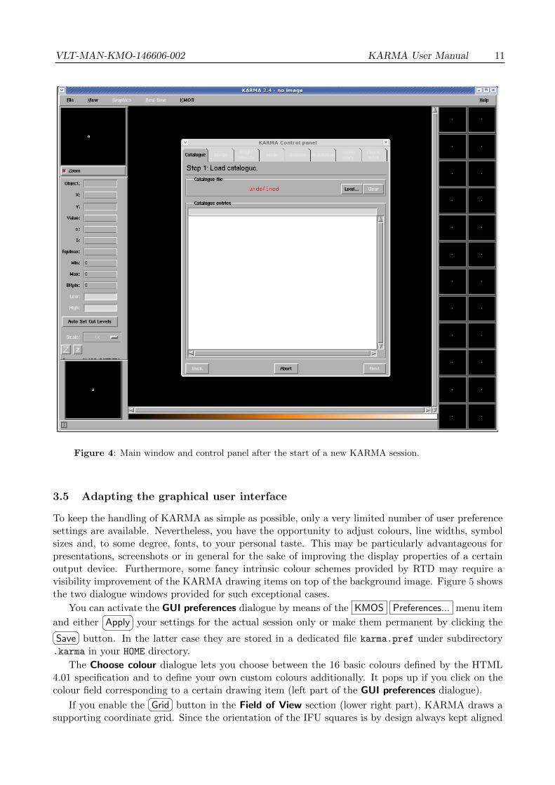
Figure 4: Main window and control panel after the start of a new KARMA session.
3.5 Adapting the graphical user interface
To keep the handling of KARMA as simple as possible, only a very limited number of user preferencesettings are available. Nevertheless, you have the opportunity to adjust colours, line widths, symbolsizes and, to some degree, fonts, to your personal taste. This may be particularly advantageous forpresentations, screenshots or in general for the sake of improving the display properties of a certainoutput device. Furthermore, some fancy intrinsic colour schemes provided by RTD may require avisibility improvement of the KARMA drawing items on top of the background image. Figure 5 showsthe two dialogue windows provided for such exceptional cases.
You can activate the GUI preferences dialogue by means of the KMOS Preferences... menu item
and either�� ��Apply your settings for the actual session only or make them permanent by clicking the�� ��Save button. In the latter case they are stored in a dedicated file karma.pref under subdirectory
.karma in your HOME directory.
The Choose colour dialogue lets you choose between the 16 basic colours defined by the HTML4.01 specification and to define your own custom colours additionally. It pops up if you click on thecolour field corresponding to a certain drawing item (left part of the GUI preferences dialogue).
If you enable the�� ��Grid button in the Field of View section (lower right part), KARMA draws a
supporting coordinate grid. Since the orientation of the IFU squares is by design always kept aligned

12 KARMA User Manual VLT-MAN-KMO-146606-002
Figure 5: Dialogue windows allowing some simple adjustments of GUI appearance. The colour
dialogue (right) pops up if you click into the colour fields of the GUI preferences dialogue (left).
with respect to the instrument (y, z) coordinate system, also the drawn grid is kept fixed. In this wayit is guaranteed that the grid lines are always parallel to the IFU boundaries. You can change thegrid spacing by means of the arcsec spinbox (only by clicking on the small arrow buttons).
Furthermore, you have the option to draw the outlines of the pick-off arm safety margin and itsshadow (for upper arms) as they are used by the internal permissibilty checks (this applies only tothose steps where the arms are visible, though). Select the checkbuttons Margin and Shadow in frameArms for this purpose. Arm numbers get displayed if you select the checkbutton Numbers.
Changing the line width (upper right part) affects all drawn lines except those of the grid.To avoid confusion, it is not possible to change the meaning of a symbol, although its size can be
adjusted (upper right part). The symbol size does not change with zoom. Anyway, the RTD zoom
buttons�� ��Z and
�� ��z will be available only if an image is loaded.In what concerns fonts, it is possible to adjust family and size of those fonts which are used
in the KARMA control panel. Edit the file appdefaults in subdirectory config for this purposeappropriately.
3.6 Disabling of single pick-off arms
By default, all KMOS pick-off arms are initially available in a KARMA session. If for technical reasonsa single one or even some of them are deliberately locked in the instrument (which could be reflectedin the configuration file kmmcfgINS.cfg, to be found in subdirectory doc), you have an option toexclude the not available ones from allocation in KARMA. For the current KMOS status, especiallyfor the information which arms are locked for which period, please check the following web page:
http://www.eso.org/sci/facilities/paranal/instruments/kmos/news.html
If a particular arm is known to be locked, you can disable it through a dedicated dialogue windowthat you get via KMOS Arm availability... (figure 6).
In the unlikely case that a broken arm is not locked at its park position but left in the field, and ifthis lock position is known, you can move the arm by means of the spin buttons to a given point andlock it afterwards. Otherwise it is sufficient to just press the arm number button in order to disable(or re-enable) the corresponding arm, which will then not be used in KARMA.
The whole feature is, however, available only in the KARMA setup steps that are related to armallocation (see sections 8 and 9). A disabled arm keeps its lock status until the end of the currentKARMA session.
Finally, if a particular arm is actually locked in the instrument but was allocated to a target inKARMA, a dedicated algorithm within the KMOS Observation Software at the instrument workstation

VLT-MAN-KMO-146606-002 KARMA User Manual 13
Figure 6: Dialogue window that allows to disable/enable individual arms. It is available via the
main menu in steps 5 and 6.
provides for an optimal instrument rotator angle (most likely different from the one specified inKARMA) so that a maximum number of the most important targets can still be observed. Thisis, of course, only possible for setups with different target priorities. For more details on rotatoroptimisation please see also the KMOS User Manual [2].
3.7 The example files
Now it’s time to have a look at the example data. You find them in subdirectory data. At the time ofwriting there are 3 examples, each of which consists of a catalogue (*.cat) and an image (*.fits) file.They cover the globular clusters M4, M5 and 47 Tuc. Though not really targets for serious KMOSobservations, the many stars contained therein and their well-known positions, respectively, are usedfor the astrometric calibration of the instrument on sky. In the context of this manual they should besuitable as tutorial examples.
All three images were created from a mosaic of image tiles taken from the 2MASS image server(http://irsa.ipac.caltech.edu/applications/2MASS/IM) by means of the SWarp tool (http://www.astromatic.net/software/swarp), the catalogues are assembled from the 2MASS online cat-alogue. In the following sections the M4 example will be used for the tutorial.

14 KARMA User Manual VLT-MAN-KMO-146606-002
4 Step 1: Prepare and load catalogue
As already mentioned, to fulfil its main purpose, KARMA requires a dedicated catalogue of positionsfor science and reference targets, which you must prepare in advance and which you are fully responsiblefor, especially for using an appropriate and consistent astrometric reference system. In particular thisapplies to the positions of potential telescope guide stars which you have to provide along with thetarget list and which possibly could be derived from another source than the targets are (usually froma public domain guide star catalogue). Additionally, the KARMA catalogue can include previouslydefined and checked sky background positions as well as the positions of bright objects to be avoided bypick-off arms because of stray light problems. In any case the input catalogue must include an initialcentre position, which is used as a reference point for all virtual telescope movements with KARMA.All these entries must be assembled in a plain ASCII file consisting of an arbitrary number of records(rows), each of which represents a celestial position of whatever type and contains the following data,organised as columns. Mandatory columns (must appear in the order given below) for each entry are:
• ID: The name of the object or position. This is any unique string of arbitrary length. It must notcontain spaces and shall otherwise consist only of alphanumeric characters (A-Z,a-z,0-9), ASCIIhyphen-minus, and underscores.
• RA and Dec: Right ascension (α) and declination (δ) of the object or position. Both decimaldegrees and HH:MM:SS.XXX (for α) or DD:MM:SS.XX (for δ) formats are accepted. For allpositions the usage of equinox J2000 is mandatory; this information therefore needs not be pro-vided explicitly. The coordinates should, however, be corrected for proper motions if necessary.According to the required positioning accuracy of KMOS, the relative accuracy of all positionsshall be better than 0.2 arcsec.
• Type: Indicated by (at least) one or multiple character flags. The following flags are defined,catalogue entries of the respective type will be displayed in the KARMA main window with thecorresponding symbols (right):
O Scientific target. Except for Mosaic mode (see section 7), the catalogue should containfor obvious reasons at least the targets you are going to observe.
R Reference target. For the main observation modes Nod to Sky and Stare (see section7), the catalogue shall contain at least two of them (KARMA checks this in step 4, atthe latest).
S Sky background position (optional). Only to be taken into consideration if you know ce-lestial positions in advance that are particularly suitable for sky background subtraction.Usually, these positions will be defined during the KARMA session interactively.
G Potential telescope guide star. At least one such entry is required, irrespective of the typeof observation you are going to prepare. Although up to 5 VLT guide star candidatescan be selected by means of KARMA, you should take into account that those beinginside a certain minimum radius will be discarded in order to avoid vignetting of theKMOS FoV (see section 10). Therefore it is advantegeous to provide a sufficient numberof G entries which are also sufficiently far off the field centre.
B Object brighter than a certain limiting magnitude (optional). Can also be defined duringthe KARMA session.
C Field centre (mandatory). Not necessarily associated with any target position but willbe used as an initial reference point, for instance during the search in the 2MASS onlinecatalogue. In Mosaic mode (see section 7) it will be probably (but not necessarily) bethe centre of the contiguous mapping field you are going to observe.
VLT-MAN-KMO-146606-002 KARMA User Manual 15
M Marker position (optional). Can be used to mark a certain celestial position in order toprovide an anchor point for better orientation. Also useful for targets whose positionshall be kept visible even if they have been already allocated.
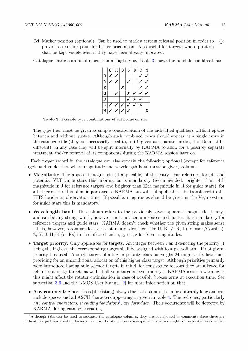
Catalogue entries can be of more than a single type. Table 3 shows the possible combinations:
O R S G B C M
O 7 3 3 3
R 3 7 3 3 3
S 7 3 3
G 3 7 3 3 3
B 3 7 3
C 3 3 3 3 3 7
M 3 3 3 3 7
Table 3: Possible type combinations of catalogue entries.
The type then must be given as simple concatenation of the individual qualifiers without spacesbetween and without quotes. Although such combined types should appear as a single entry inthe catalogue file (they not necessarily need to, but if given as separate entries, the IDs must bedifferent), in any case they will be split internally by KARMA to allow for a possibly separatetreatment and/or removal of its components during the KARMA session later on.
Each target record in the catalogue can also contain the following optional (except for referencetargets and guide stars where magnitude and wavelength band must be given) columns:
• Magnitude: The apparent magnitude (if applicable) of the entry. For reference targets andpotential VLT guide stars this information is mandatory (recommended: brighter than 14thmagnitude in J for reference targets and brighter than 12th magnitude in R for guide stars), forall other entries it is of no importance to KARMA but will – if applicable – be transferred to theFITS header at observation time. If possible, magnitudes should be given in the Vega system,for guide stars this is mandatory.
• Wavelength band: This column refers to the previously given apparent magnitude (if any)and can be any string, which, however, must not contain spaces and quotes. It is mandatory forreference targets and guide stars. KARMA doesn’t check whether the given string makes sense– it is, however, recommended to use standard identifiers like U, B, V, R, I (Johnson/Cousins),Z, Y, J, H, K (or Ks) in the infrared and u, g, r, i, z for Sloan magnitudes.
• Target priority: Only applicable for targets. An integer between 1 an 3 denoting the priority (1being the highest) the corresponding target shall be assigned with to a pick-off arm. If not given,priority 1 is used. A single target of a higher priority class outweighs 24 targets of a lower oneproviding for an unconditional allocation of this higher class target. Although priorities primarilywere introduced having only science targets in mind, for consistency reasons they are allowed forreference and sky targets as well. If all your targets have priority 1, KARMA issues a warning asthis might affect the rotator optimisation in case of possibly broken arms at execution time. Seesubsection 3.6 and the KMOS User Manual [2] for more information on that.
• Any comment: Since this is (if existing) always the last column, it can be abitrarily long and caninclude spaces and all ASCII characters appearing in green in table 4. The red ones, particularlyany control characters, including tabulators4, are forbidden. Their occurrence will be detected byKARMA during catalogue reading.
4Although tabs can be used to separate the catalogue columns, they are not allowed in comments since these arewithout change transferred to the instrument workstation where some special characters might not be treated as expected.

16 KARMA User Manual VLT-MAN-KMO-146606-002
0 1 2 3 4 5 6 7 8 9 A B C D E F
0 NUL SOH STX ETX EOT ENQ ACK BEL BS HT LF VT FF CR SO SI
1 DLE DC1 DC2 DC3 DC4 NAK SYN ETB CAN EM SUB ESC FS GS RS US
2 SP ! " # $ % & ’ ( ) * + , - . /
3 0 1 2 3 4 5 6 7 8 9 : ; < = > ?
4 @ A B C D E F G H I J K L M N O
5 P Q R S T U V W X Y Z [ \ ] ^
6 ‘ a b c d e f g h i j k l m n o
7 p q r s t u v w x y z { | } ~ DEL
Table 4: ASCII set with characters allowed (green) and forbidden (red) in catalogue comments.
All columns must be separated by spaces and/or tabs and appear on the same line. An omittedoptional column must be replaced by an asterisk (*) in case there are remaining columns with dataprovided before the end of the line. Furthermore, the catalogue can include an arbitrary number ofcomment lines beginning with #. As an example of a user defined input catalogue the M4 catalogueused in the tutorial example is given in appendix B. Compare with this example and create your owncatalogue with any suitable editor. If you do this on a system other than Linux or Mac OS X or ifyou transfer your catalogue files via e-mail, you should take care that no DOS-like carriage returns areadded to the lines of the text file. Since these special characters, usually never appearing in Unix-likeASCII files, may hamper the execution of an Observation Block at the instrument workstation if theyaccidentally make it to the PAF file, KARMA checks for such occurrences and rejects a catalogue fileas corrupted if any carriage return has been found.
Figure 7: Control panel after having loaded the example input catalogue M4.cat.
Furthermore, in case of other serious deficiencies (no centre given, no guide star), KARMA willreject the whole catalogue, too. In addition, KARMA checks each entry for syntactical and, as faras possible, also for semantical correctness. Invalid entries will be rejected. Concerning the Mosaicobservation mode (mapping of a contiguous field with a predefined arm configuration), in principle no

VLT-MAN-KMO-146606-002 KARMA User Manual 17
scientific or reference targets need be prepared in advance as the initial position of the arm pattern willbe defined interactively using KARMA and since this mode is executed without acquisition. Providinga catalogue is necessary even in this case with the exception that the reference targets can be omitted.
If you now load the M4 example catalogue simply by clicking the�� ��Load button in the control panel
(figure 7) and choosing the appropriate file M4.cat from the standard file dialogue (for the sake of
simplicity, all targets here have priority 1 – ignore the warning and press�� ��Load anyway ), the list in the
lower part of the current control panel page gets filled, and the corresponding entries will be displayedas symbols in the KARMA main window (figure 8). If you click on a list item in the control panel, thecorresponding symbol in the main window flashes. If, the other way around, you click on a symbol (its
outline), the corresponding list item gets highlighted. You can Disable items, i.e. catalogue entries(except the field centre) via a context menu that you get by clicking on an activated list item with theright mouse button. Regardless of their type, disabled catalogue entries are excluded from all furtherKARMA operations and the corresponding symbol in the main window vanishes. Disabled entries canbe enabled again via Enable . You can delete the whole catalogue, if necessary, with
�� ��Clear .
Figure 8: Main window after having loaded the example input catalogue M4.cat. The different
symbols denote the different types of catalogue entries and their positions within the KMOS field of
view, enclosed by the inner circle. The outer circle forms the inner boundary of the avoidance zone
for guide star selection if the observation were to be performed at the current position.

18 KARMA User Manual VLT-MAN-KMO-146606-002
If you want to change a particular catalogue entry, it is highly recommended to edit the cataloguefile and
�� ��Load it again. In exceptional cases (you might want to add a comment or change thepriority of a target) it is, however, also possible to modify catalogue positions afterwards by means ofa dedicated dialogue (figure 9). You get it via the context menu (right mouse button on list item and
Edit ... ), too. Editing of disabled entries and allocated targets is not allowed.
Figure 9: Dialogue window that allows for the editing of catalogue entries after the catalogue file
has been loaded. It should be used only in exceptional cases.
Once you have checked that all catalogue entries are really displayed and if you have identified thecorresponding symbols, you can go to the
�� ��Next step.

VLT-MAN-KMO-146606-002 KARMA User Manual 19
5 Step 2: Load image
After having loaded your catalogue, in principle you could carry out the whole KARMA sessionwithout any additional input, assuming however, that suitable sky background positions have beenprovided along with the input catalogue. This is usually not the case. Instead, you determine yoursky background only after the science target allocation as described in section 8. In addition, youwant to have a clue about what you are doing and whether your allocated arms are really placed onthe objects you are going to observe. Therefore it is strongly recommended that you provide a FITSimage covering your target field.
Since KMOS has no imaging mode, this image can be taken from any source. A convenientway is, for example, to retrieve it from the 2MASS image server at http://irsa.ipac.caltech.
edu/applications/2MASS/IM. In combination with the SWarp tool (http://www.astromatic.net/software/swarp) it is even possible to construct large area image mosaics.
However, in no way the image will serve as a reference system for any astrometric position. Allowingfor celestial positions derived from an image of arbitrary source would introduce too many degrees ofuncertainty. Thus, it is not possible in KARMA to define additional targets by means of the imagealone (except the sky background positions where absolute accuracy is not that important, see sections8 and 9).
Therefore it must be emphasised again that the careful preparation of your catalogue is really themost crucial part of the whole preparation cycle. Most probably, however, the image you provide willbe also the one where you already have derived your catalogue positions from. Then, a discrepancybetween catalogue positions and their location on the image can arise only for catalogue entries youhave taken from another source, perhaps from a public domain guide star catalogue. Unfortunately,there is no easy way out of this kind of misalignment. You must take care of having the sameastrometric reference system anyhow, for instance by aligning object positions which are both availablein the guide star catalogue and your image (or whatever sources you want to fit). Catalogue positionsshould also be corrected for proper motions if necessary.
Figure 10: The control panel before and after having loaded the example image M4.fits.

20 KARMA User Manual VLT-MAN-KMO-146606-002
Now have a look at the control panel. You see again the�� ��Load and
�� ��Clear buttons like in theprevious step. Their purpose with respect to the image should be self-explanatory. The lower part ofthe current control panel page is intended to give you an overview of size and position of the KMOSFoV with respect to the image once it is loaded. Just try this out now and load the example imageM4.fits. Your control panel now should look like in figure 10. Since KARMA scales the imageautomatically in such a way that it is fully visible, it can take a few seconds until it gets displayed.The main window then should look like in figure 11. Its display properties depend on the currentRTD settings. If colours appear too strange, first try the RTD feature
�� ��Auto Set Cut Levels , try outdifferent values for the lower and upper cuts (they are subject to the KARMA history mechanism,
i.e. the cut levels will not survive if you go�� ��Back to a previous step) or check the different options
provided by the View item of the main window menu bar. You can also zoom in and out now by
means of the RTD zoom buttons�� ��Z and
�� ��z . Explaining all the display capabilities of RTD is, however,beyond the scope of this manual. Consult the RTD User Manual [1] in this case. Remember also the
possibility to adjust symbol sizes and colours by means of the KMOS Preferences... menu in case ofbad visibility.
Figure 11: The main window after having loaded the example image M4.fits. Suitable display
properties have been achieved by adjusting the cut levels.
The alignment of the KMOS FoV with respect to the image will be carried out simply by deter-mining the image pixel corresponding to the catalogue centre position (this is one of the reasons why

VLT-MAN-KMO-146606-002 KARMA User Manual 21
you had to provide it) from the FITS header, assuming that the appropriate WCS header keywordsare present. The KMOS FoV will then be drawn at this position. In addition, it will be rotated sothat the instrument coordinate system is aligned with the axes of right ascension and declination. Youdon’t need to care about this, but it might be useful to know that an image alignment with α and δ isnot necessary. The lower part of the current control panel page indicates the orientation of the imagewith respect to the sky coordinates.
If your control panel looks like figure 10 and the main window similar to figure 11, you are donewith this step and you can go to the
�� ��Next one.What can go wrong? If the image does not cover the KMOS FoV completely, you will get a
warning, but KARMA will accept the image anyway. If, however, the image does not even overlapwith the FoV, you have probably chosen the wrong one, or the WCS header information is wrong. Itwill be useless and therefore be rejected.

22 KARMA User Manual VLT-MAN-KMO-146606-002
6 Step 3: Identify bright objects
As already mentioned in section 4 where you have prepared your catalogue, the metallic pick-off armsurfaces can cause stray light contaminating the frames taken by other arms. Therefore it shall beavoided at least to place the upper level arms at positions where they can be hit by very bright skyobjects. Thus, KARMA must know these objects beforehand to take them into account during armand target allocation, respectively.
Complementing those positions which were already provided along with the input catalogue, ad-ditional ones now can be defined by querying the 2MASS online catalogue server at http://irsa.
ipac.caltech.edu/applications/Gator automatically. To a certain extent this step is therefore anoptional one. You can skip it if you think your bright object list is already sufficient or if you don’tcare about bright objects at all. Otherwise you are allowed to specify a search radius and a limitingmagnitude for the J band here – the 2MASS server will then provide you with a list of either point orextended source positions enclosed within the search area in J2000 coordinates.
You can see the default values for both these settings already displayed in the correspondingentry fields of the current control panel page. You can overwrite them, your input will be checkedfor plausibility. Although for the arm allocation itself only those objects will be considered whichare inside the KMOS FoV then, the search radius (which is meant relative to the catalogue centreposition) should be somewhat greater than the FoV radius to allow for the inevitable telescope offsetsto be specified in later steps. Finally, by means of the 2 radio buttons you can choose between pointand extended source search.
To try this all out now, first check if your computer is connected with the internet. If so, specifyyour search values and simply click
�� ��Search . It usually takes a few seconds until you get the resultlist. If you leave the default values as they are, the control panel then should look like in figure 12and the main window like in figure 13.
Figure 12: The control panel displaying the additional bright objects retrieved from the 2MASS
catalogue using default values for search radius and limiting magnitude.
VLT-MAN-KMO-146606-002 KARMA User Manual 23
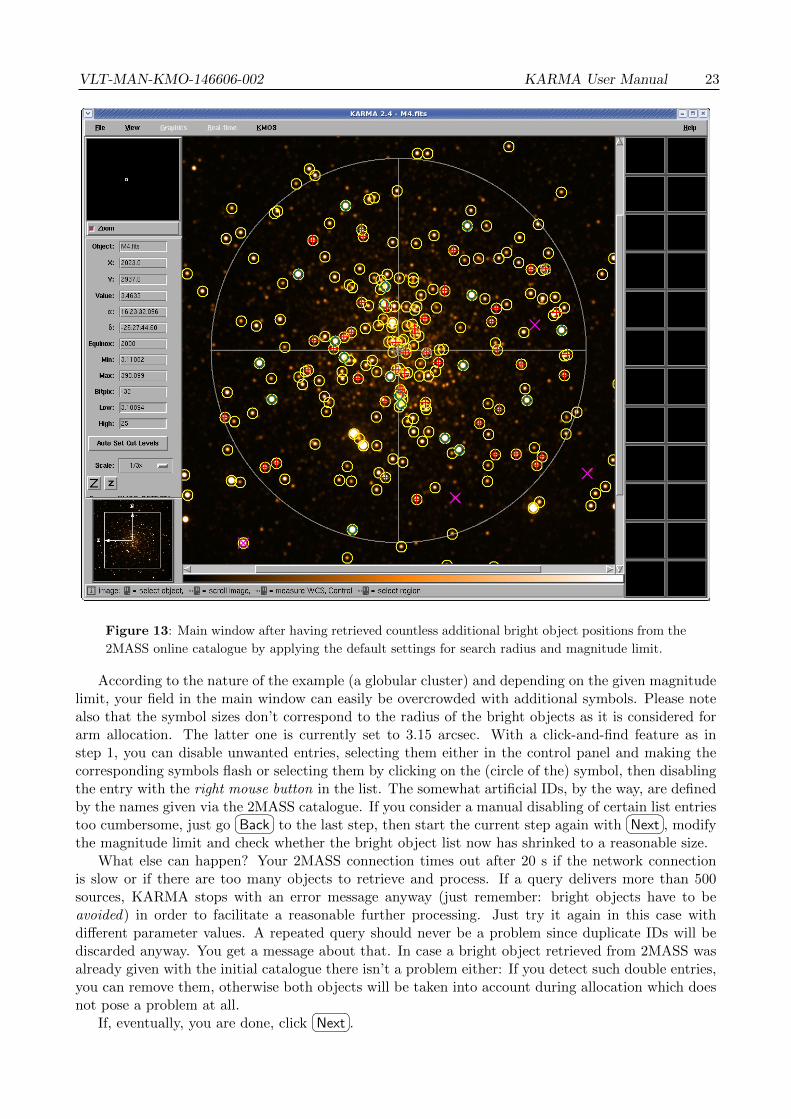
Figure 13: Main window after having retrieved countless additional bright object positions from the
2MASS online catalogue by applying the default settings for search radius and magnitude limit.
According to the nature of the example (a globular cluster) and depending on the given magnitudelimit, your field in the main window can easily be overcrowded with additional symbols. Please notealso that the symbol sizes don’t correspond to the radius of the bright objects as it is considered forarm allocation. The latter one is currently set to 3.15 arcsec. With a click-and-find feature as instep 1, you can disable unwanted entries, selecting them either in the control panel and making thecorresponding symbols flash or selecting them by clicking on the (circle of the) symbol, then disablingthe entry with the right mouse button in the list. The somewhat artificial IDs, by the way, are definedby the names given via the 2MASS catalogue. If you consider a manual disabling of certain list entriestoo cumbersome, just go
�� ��Back to the last step, then start the current step again with�� ��Next , modify
the magnitude limit and check whether the bright object list now has shrinked to a reasonable size.What else can happen? Your 2MASS connection times out after 20 s if the network connection
is slow or if there are too many objects to retrieve and process. If a query delivers more than 500sources, KARMA stops with an error message anyway (just remember: bright objects have to beavoided) in order to facilitate a reasonable further processing. Just try it again in this case withdifferent parameter values. A repeated query should never be a problem since duplicate IDs will bediscarded anyway. You get a message about that. In case a bright object retrieved from 2MASS wasalready given with the initial catalogue there isn’t a problem either: If you detect such double entries,you can remove them, otherwise both objects will be taken into account during allocation which doesnot pose a problem at all.
If, eventually, you are done, click�� ��Next .

24 KARMA User Manual VLT-MAN-KMO-146606-002
7 Step 4: Choose observing mode
Although KMOS is a rather complex instrument, it offers essentially only a single observation mode:Integral Field Spectroscopy. This is the case at least in the sense as the term observation mode isusually understood within the context of VLT instrumentation. Apart from that, however, KMOSknows three different modes, whereof two are mainly distincted by the way the sky background signalis determined. The third allows for the observation of contiguous fields on sky instead of single targets.See figure 14 below.
Nod to Sky Stare Mosaic
Tel
esco
peat
Sky
posi
tion
Tel
esco
peat
Scie
nce
posi
tion
sky arm
Figure 14: Schematics of the three observation modes configurable by KARMA: Nod to Sky, Stareand Mosaic. Depending on the current telescope position, an arm is either allocated to a sciencetarget or to sky background. The offsets between Science and Sky position are performed by thetelescope alone while the pick-off arms remain fixed at their positions in the focal plane.
(Only a few IFUs are depicted. Not drawn to scale.)
In the following, they shall be somewhat sloppy called observation modes, too. We assume thatyou are already familiar with the basic principles of these modes as they were already described in theKMOS User Manual [2]. If not, look up there first. Nevertheless, the following subsections provideagain a short description of each mode as you are advised to make your choice right now by means ofKARMA.
7.1 Nod to Sky mode
In this mode the sky background signal is obtained by moving (nodding) the telescope and/or rotatingthe instrument between two previously defined positions, depicted by the two schematic configurationsin the left column of figure 14.
Therefore each pick-off arm (IFU represented schematically by a black square) switches between itsscientific target (red bullet) and a corresponding own sky background position (blue square). The latter

VLT-MAN-KMO-146606-002 KARMA User Manual 25
one has to be found during the next preparation step. In the process of nodding only the telescopeand/or instrument rotator positions are altered, the pick-off arm configuration remains unchanged.
Since it is unlikely that all 24 arms can be allocated at once to scientific targets within a singletelescope/instrument position, it is possible to assign not used arms to remaining targets in the secondposition where the already allocated arms are usually covering blank sky (see subsection 8.3). Thisleads to a configuration where in both telescope/instrument positions (left column of figure 14) onesubset of arms is allocated to scientific targets and another subset to sky background.
7.2 Stare mode
The characteristic feature of this mode is that the telescope always points (stares) to the same positionas well as the instrument rotation angle doesn’t change (upper part of second column in figure 14).
The sky background then will be obtained by dedicated sky arms, which, in contrast to the Nod toSky mode, deliver a signal which is picked not by the same IFU as for the scientific target. All pick-offarms allocated to science targets can, however, serve for sky background subtraction simultaneouslyif their IFUs contain a sufficient number of empty sky pixels.
A dedicated sky position (lower part of second column in figure 14) where all arms are observingblank sky in addition is necessary only once or at least less frequently than in Nod to Sky mode. Youcannot allocate additional science targets there.
7.3 Mosaic mode
For the spectroscopic observation of contiguous fields on sky, KMOS provides two dedicated config-urations, known as Mosaic mode, where the individual IFUs of either all the 24 or of a subset of 8pick-off arms are arranged in such a way that with successive telescope pointings a rectangular areacan be covered step by step. For data reduction a single sky background position as in the othermodes is necessary (figure 14, third column).
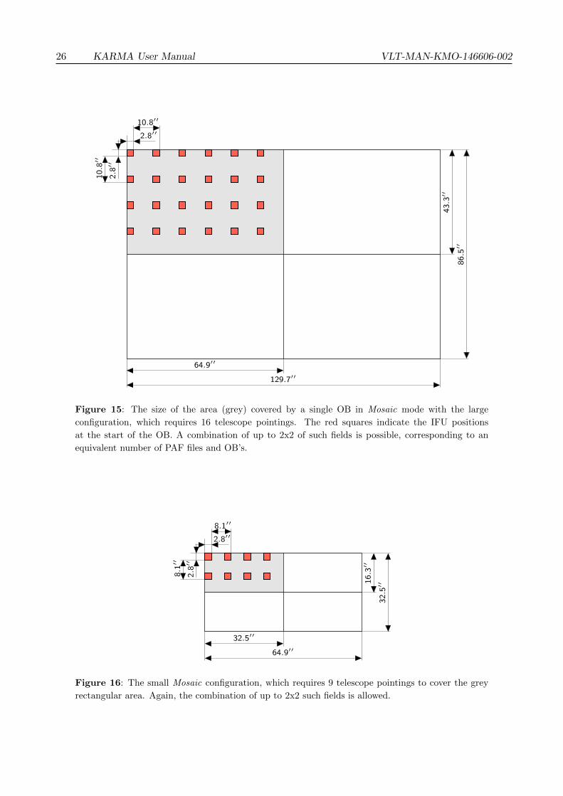
For the two existing predefined configurations the participating arms are allocated to fixed positionsforming a 6x4 or a 4x2 array. Figure 15 and figure 16 in their upper left parts show the positions ofthe IFU’s (red squares) in these arrangements for the first telescope pointing, starting in the upperleft corner.5 The observation block that you prepare will contain just this first pointing along withthe appropriate arm positions. All subsequent telescope offsets, however, will be calculated by theinstrument control software automatically during the OB execution. To allow for a possible tilt, thegaps between the IFU’s are slightly smaller than an integer multiple (here: three and two) of the IFUsize. With the given configurations it is thus possible to map rectangular areas of 2810 and 530 squarearc seconds with 16 and 9 telescope pointings, respectively, in a single OB.
In the unlikely case that even such a comparatively large field as the 6x4 one is still too small tofulfil your scientific requirements or if you are going to repeat the same observation with a slightlyshifted field in order to enable smooth transitions between the individual IFUs during data reduction,KARMA opens up the possibility to combine up to 4 of these rectangular areas, leading to an equivalentnumber of PAF files and OBs. The positions of the individual mapping areas and hence the size ofyour “super field”, the maximum dimension of which you can again see in figures 15 and 16, must bespecified already during the current step then.
5Please note that the IFUs are arranged symmetrically around the FoV centre. Thus, the telescope optical axis atthe first pointing is located not at the upper left corner of the mapping area but in the middle of the IFU configuration.In figure 15 this is between“row” 2 and 3 and “column” 3 and 4, respectively.
26 KARMA User Manual VLT-MAN-KMO-146606-002
10.8′′
2.8′′
2.8′
′10
.8′′
64.9′′
129.7′′
43.3
′′
86.5
′′
Figure 15: The size of the area (grey) covered by a single OB in Mosaic mode with the large
configuration, which requires 16 telescope pointings. The red squares indicate the IFU positions
at the start of the OB. A combination of up to 2x2 of such fields is possible, corresponding to an
equivalent number of PAF files and OB’s.
8.1′′
2.8′′
2.8′
′8.
1′′
32.5′′
64.9′′
16.3
′′
32.5
′′
Figure 16: The small Mosaic configuration, which requires 9 telescope pointings to cover the grey
rectangular area. Again, the combination of up to 2x2 such fields is allowed.
VLT-MAN-KMO-146606-002 KARMA User Manual 27
7.4 Switching between the modes
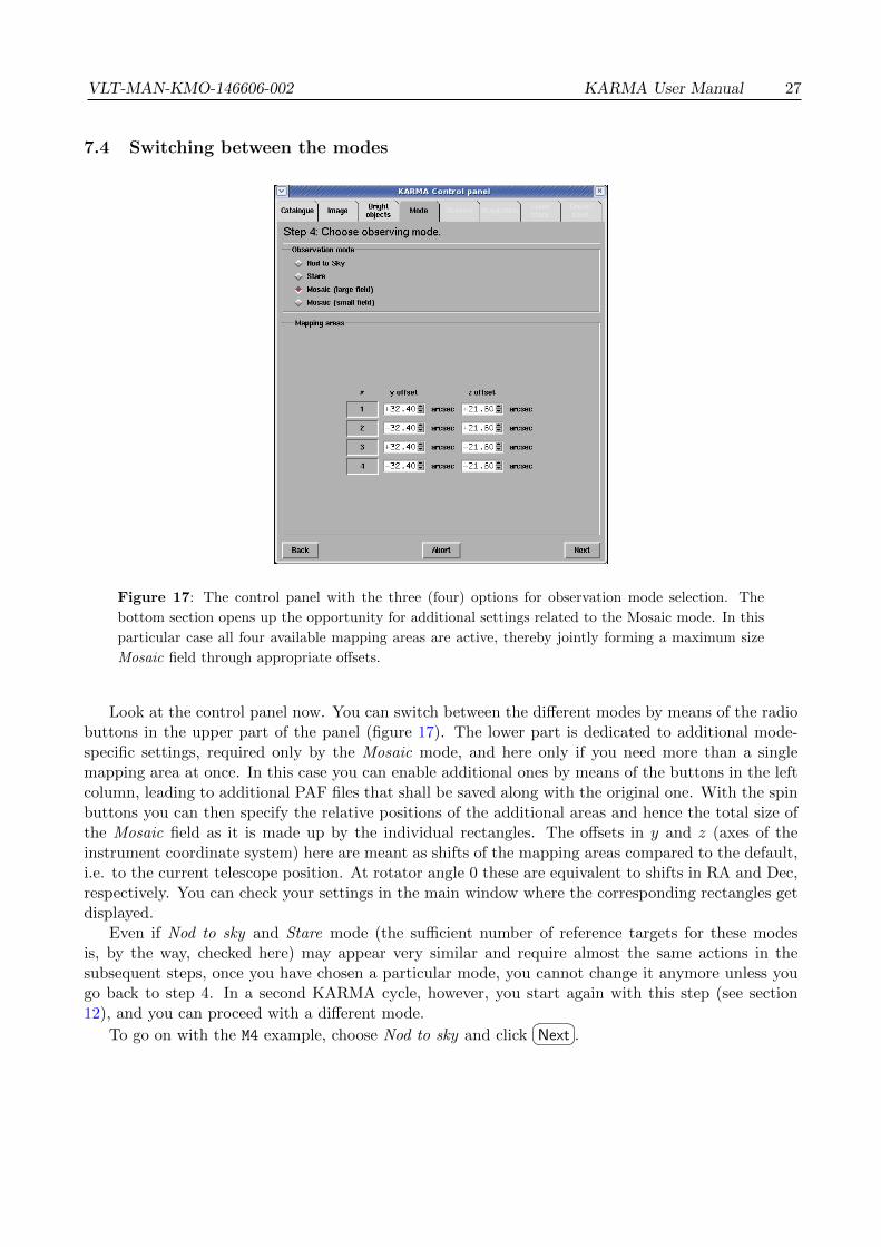
Figure 17: The control panel with the three (four) options for observation mode selection. The
bottom section opens up the opportunity for additional settings related to the Mosaic mode. In this
particular case all four available mapping areas are active, thereby jointly forming a maximum size
Mosaic field through appropriate offsets.
Look at the control panel now. You can switch between the different modes by means of the radiobuttons in the upper part of the panel (figure 17). The lower part is dedicated to additional mode-specific settings, required only by the Mosaic mode, and here only if you need more than a singlemapping area at once. In this case you can enable additional ones by means of the buttons in the leftcolumn, leading to additional PAF files that shall be saved along with the original one. With the spinbuttons you can then specify the relative positions of the additional areas and hence the total size ofthe Mosaic field as it is made up by the individual rectangles. The offsets in y and z (axes of theinstrument coordinate system) here are meant as shifts of the mapping areas compared to the default,i.e. to the current telescope position. At rotator angle 0 these are equivalent to shifts in RA and Dec,respectively. You can check your settings in the main window where the corresponding rectangles getdisplayed.
Even if Nod to sky and Stare mode (the sufficient number of reference targets for these modesis, by the way, checked here) may appear very similar and require almost the same actions in thesubsequent steps, once you have chosen a particular mode, you cannot change it anymore unless yougo back to step 4. In a second KARMA cycle, however, you start again with this step (see section12), and you can proceed with a different mode.
To go on with the M4 example, choose Nod to sky and click�� ��Next .
28 KARMA User Manual VLT-MAN-KMO-146606-002
8 Step 5: Define arm configuration for science observation
Now, after all these necessary preliminaries, you eventually have reached the most important stepof the whole KARMA session: The pick-off arm allocation itself. For this reason the main window(except for the Mosaic mode) now shows all 24 arms in their rest position. As you probably rememberfrom the KMOS User Manual [2], they are located in two planes (12 arms each). Therefore they arecoloured differently: blue for the bottom layer and green for the top one. If you want to disableparticular arms deliberately and thereby exclude them from the allocation process, you can do thatas described in subsection 3.6. In step 5 you have to perform three tasks:
1. To define telescope position and instrument rotator angle,
2. to assign targets to the pick-off arms and
3. to find a suitable sky background position for those arms which were assigned science (and possiblyalso reference targets), respectively.
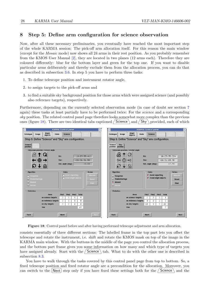
Furthermore, depending on the currently selected observation mode (in case of doubt see section 7again) these tasks at least partially have to be performed twice: For the science and a correspondingsky position. The related control panel page therefore looks somewhat more complex than the previousones (figure 18). There are two identical tabs captioned �Science A and �Sky A provided, each of which
Figure 18: Control panel before and after having performed telescope adjustment and arm allocation.
consists essentially of three different sections: The labelled frame in the top part lets you offset thetelescope and rotate the instrument, i.e. shift and rotate the KMOS mask on top of the image in theKARMA main window. With the buttons in the middle of the page you control the allocation process,and the bottom part frame gives you some information on how many and which type of targets youhave assigned already. Start with the �Science A tab. What to do with the other one is described insubsection 8.3.
You have to walk through the tasks covered by this control panel page from top to bottom. So, afixed telescope position and fixed rotator angle are a precondition for the allocation. Moreover, youcan switch to the
�� ��Next step only if you have fixed these settings both for the �Science A and the

VLT-MAN-KMO-146606-002 KARMA User Manual 29
�Sky A position and panel tab. This is anyway not possible without having allocated at least a singletarget.
The several activities to undertake, the different options you have and the underlying allocationalgorithms are explained in more detail in the next subsections.
8.1 Fixing telescope position and instrument rotator angle
In the labelled frame Telescope position/rotator angle you find on the left side a panel of buttons.With the arrow buttons you can move the telescope (virtually, of course...) in direction of increasingand decreasing right ascension (left and right) and declination (up and down), respectively. Thesedirections need not necessarily coincide with the image axes. Most images, however, will be orientedalong RA and Dec, though. In these cases the KMOS mask will, as the buttons suggest, be shiftedindeed left, right, up and down, respectively. Just try this out. The step size in both directions isfixed to 2.5 arc seconds. You can also edit the RA and Dec fields directly. Starting with the defaulttelescope pointing given with your catalogue centre, you must find now the most suitable position foryour observation. In Nod to sky and Stare mode this means that a maximum of targets (or, moreprecisely, a maximum of those with the highest priority) should be inside the field of view. Most likelyyou have already prepared your catalogue in such a way that the catalogue centre is the centre ofthe target field, and in a majority of cases you even have all the targets inside already. Then youdon’t need to change anything here for the time being. Certainly, however, you must do so when youspecify the sky background position later on. The same applies to the rotate buttons. Unless thereare broken and therefore locked arms deployed in the field (see subsection 3.6), you can at first leavethe instrument rotator angle as it is. By definition the default angle of 0 degrees corresponds to aninstrument (focal plane) coordinate system exactly aligned with RA and Dec. Note that KARMAallows to rotate the instrument (and the KMOS mask in the main window) to arbitrary angles (inmultiples of 7.5 degrees by means of the buttons and more precisely if you enter a value into the Rot.angle field directly). The actual minimum rotation angle and its sign and rotation direction will bethen determined by the instrument control software. Through the telescope software the instrumentrotation is limited to +/- 270 degrees. You can, by the way, always restore the initial (cataloguecentre) position and the default angle of 0 degrees via the crosshairs button in the centre of the panel.
In Mosaic mode things are slightly different: You probably need the shift and rotate buttons toplace the outlining mask at the position you want KMOS to observe a contiguous field and to give itthe proper orientation on sky.
Anyway, if you think you are done, press (click) the button with the closed padlock in the lowerright corner of the button panel. Once fixed, you can’t change the just made settings anymore unlessyou release the button panel again through the open padlock. This is in principle always possible butyou must not have allocated arms yet.
You have to do the same steps again when looking for the sky background position. See the relatedsubsection 8.3 below.
8.2 Allocating the pick-off arms
The main task of KARMA is to create a feasible and efficient assignment of pick-off arms to scientifictargets. Considering the several science cases driving the development of KMOS, a typical catalogueprepared for a KMOS observation will contain from a few dozens up to approximately 100 of suchscience objects. These can, as already mentioned, be prioritised, ranking them from class 1 to 3 withdecreasing priority (1 being the highest). The goal of any arm allocation method therefore must beto maximise the number of highest priority targets assigned to pick-off arms, thereby leaving as fewarms as possible unallocated. This is essentially a combinatorial problem.
Unfortunately, even for a comparatively small catalogue of 24 targets corresponding to the 24arms a naive one-by-one approach is ruled out because of the sheer number of 24! ≈ 6.2 · 1023 possible

30 KARMA User Manual VLT-MAN-KMO-146606-002
combinations. Moreover, the target-arm assignment is subject to several additional constraints:
1. The travel range of the pick-off arms is limited for the linear as well as for the angular movement.
2. Any two arms of the same plane should not collide. Moreover, there should be a minimumdistance between them to allow for later corrections of differential atmospheric effects within theInstrument Software at observation time.
3. The vignetting of lower plane IFUs by arms of the upper plane has to be avoided.
4. To avoid unnecessary stray light emanating from its metallic surface, an arm from the upperplane should not be hit by sky objects brighter than a certain limiting magnitude.
5. Failed and therefore locked arms (you can disable particular arms deliberately, see subsection3.6) can not be moved and must not be assigned to targets although they are still subject to theother constraints.
For each possible combination of target-arm assignment pairs all these constraints have to be takeninto account, partly requiring expensive computations. For this reason also a random approach likethat represented by genetic algorithms is ruled out. Instead, two dedicated automatic optimisationalgorithms are provided, complemented by the trivial method of allocating pick-off arms manually.
You select one of the allocation algorithm with the dedicated radio button box Algorithm onthe left side of the middle frame in the control panel (see figure 18, right). Depending on yourchosen observation mode not all options might be available: In Mosaic mode, of course, only thecorresponding allocation method is possible – it is then already preselected for you. The other wayaround, the Mosaic allocator is not available for Nod to Sky and Stare mode.
The allocation itself can be invoked by means of the�� ��Allocate button (middle right). You then see
the result immediately in the main window: The allocated arms are deployed to their target positions,the symbols corresponding to assigned targets turn white (figure 19). In addition, the 24 IFU windowson the right border of the main window now reveal their function for the first time: For the armsallocated to targets you see the targets magnified in their associated windows along with the IFUsquare as it covers the target.
With the�� ��Reset button you can undo the whole allocation: All arms will be set back to their rest
position. If you only want to reset a single arm, you must select the�� ��Manual method first and click
with the right mouse button on the tip of the appropriate arm. See also subsection 8.2.3 on this topic.To begin with, the following subsections describe the implemented allocation methods which you
can choose from. You can skip subsections 8.2.1 and 8.2.2 if you are not interested in those details.
8.2.1 Hungarian Algorithm
The allocation by means of the Hungarian Algorithm is based on a standard method in mathematicaloptimisation theory (for the original paper see [5]). The basic principle here consists in the assignmentof any m objects of one set to any n objects of an other set by minimising/maximising the total costof the assignment regarding a special optimisation criterion. Formally, for a given cost matrix
C =
c11 c12 · · · c1nc21 c22 · · · c2n...
.... . .
...cm1 cm2 · · · cmn
(1)
a corresponding assignment matrix X with xij ∈ {0, 1} must be found in such a way that
Z =m∑i=1
n∑j=1
cijxij!
= min

VLT-MAN-KMO-146606-002 KARMA User Manual 31
Figure 19: The main window after automatic allocation with Hungarian Algorithm. Arm 16 has
been allocated manually at � Sky A position.
In the case of the target-arm assignment problem the optimisation criterion and hence the cost matrixcan be found in the sum over the distances from the pivot axis of each arm to its assigned target for allpossible assignment pairs simultaneously. Such an approach directly follows from the fact that the sumover the distances axis-target for any two target-arm pairs is minimum for the case in which the armsdon’t cross. Thus, the overall sum over the target-axis distances is also minimum and the constraint ofcollision-free assignment (for dimensionless arms, though) is fulfilled by the algorithm in a natural way.Regarding the other constraints, not all of them can be taken into account simultaneously. Therefore,always a few assignment pairs obtained by application of the algorithm must be discarded afterwardsby moving all arms to their destination position virtually and checking whether the new position ispermitted. The eclipse of a lower plane IFU, however, can be avoided easily by the assignment of lowerplane arms to targets in the centre and the assignment of upper plane arms to more outward targets.In addition, the impossible assignments due to the limited travel range can be excluded partially bygiving them a factor 2 penalty in the initial cost matrix. Embedding the central optimisation algorithminto the more general assignment procedure and allowing for the remaining constraints (bright objecthits, failed arms), the following sequence of steps arises. Essentially, it forms a two-stage method,allocating the bottom layer arms in a first stage and the top layer arms in a second one:
1. Select the reachable targets and exclude those outside FoV. Restrict to the highest availablepriority class.
32 KARMA User Manual VLT-MAN-KMO-146606-002
2. Select the 12 innermost targets. Begin with the target which has minimum distance to the centreof FoV.
3. Assign these just selected inner targets to bottom layer arms by applying the Hungarian Algo-rithm.
4. Check whether the obtained assignments are permitted with respect to the several constraints.Discard those assignment pairs which are not. Sort out the corresponding targets and make themavailable for subsequent assignments again.
5. Draw an imaginary boundary around the assigned inner targets. Exclude all not yet assignedtargets inside this area from the list of available targets.
6. Assign the best fitting targets, i.e. only those with highest priority from those still remaining totop layer arms by applying the Hungarian Algorithm again.
7. Check for impermissible assignments like in step 4. Discard the pairs violating a certain constraint.Sort out the corresponding targets and make them available for subsequent assignments.
Because of its simultaneous nature the Hungarian algorithm is best suited for equally-weighted targets.In order to maintain the requirement of collision-free assignment all targets must be handled equally.Targets of lower priority can be considered only in case all those with higher priority are alreadyassigned.
8.2.2 Stable Marriage Algorithm
In contrast to the Hungarian Algorithm above, the Stable Marriage Algorithm provides an alternativeoptimisation method which is better suited for more heterogeneous sets of targets. It is based on astandard algorithm of optimisation theory, too. For the original reference see [6]. The Stable MarriageProblem (SMP) in its usual form is the following:
Given a set of men and a set of women (each set obviously replaceable by a set of any species,objects etc. and in particular targets and pick-off arms), find a set of marriages between the men andwomen so that all marriages are stable. Stable in this context means that no pair across two marriagesexists in which the two people of opposite sex prefer each other to their current married partners.
It can be proven mathematically that the SMP can always be solved so that all marriages arestable. For the details of the solution algorithm (the Stable Marriage Algorithm, SMA) we refer againto appropriate textbooks.
As a precondition for each member of both sets (men and women or, obviously, targets andarms) there is always a ranking list of all the members of the opposite set required. Applied to thetarget-arm assignment problem, such an approach is clearly suitable for the incorporation of severalconstraints simultaneously. In particular, for the ranking of arms by targets the sorting accordingto the travel distance as in the Hungarian Algorithm is the most suitable criterion, allowing for thecollision constraint. The opposite ranking of targets by arms, however, can be made easily accordingto the target priority, thereby sorting the subsets of targets with same priorities again with respectto the travel distance. Impossible pairings exceeding the maximum travel can be excluded right fromthe start.
Applying this idea to the fundamental optimisation problem, a stable pairing between targets andarms can be obtained as follows:
1. Create preference lists for targets and arms. For each arm sort all targets according to theirpriority and then according to their distance from the arm axis. For each target, sort all armsaccording to their axis distance. Discard list entries which would belong to an impossible pairing.

VLT-MAN-KMO-146606-002 KARMA User Manual 33
2. Begin with any of the targets and assign the pick-off arm which is highest ranked for this particularone.
3. Take the next target and try to assign the highest ranked arm for this second target. If thecorresponding arm is already assigned, compare its ranking for the current (second) target withthe ranking of the target to which it is assigned (the first one). In case the affinity to the currenttarget is higher than to the already matched one, disconnect the existing assignment and assignthe arm to the current target. The target which was previously assigned to the same arm is nowavailable again. In case the existing assignment is stronger, take the arm which is next in theranking and try the same.
Repeat point 2 and 3 until either all arms are assigned or there are no available targets anymore.
4. Remove those assignments from the configuration which violate the collision, eclipsing and brightobject constraints. Make the corresponding targets available again for subsequent allocations.
8.2.3 Manual Allocation
As a supplement to the automatic methods described above, you have always the possibility to allocateand deallocate single arms interactively. Select
�� ��Manual in the Algorithm frame for this purpose. Thengrab a free arm (which is not assigned to a target yet) in the main window by clicking on the centreof its tip. If you want to change the position of an arm already assigned to a target, you must resetit before. A right-button click on its tip centre does it: The arm snaps back into its rest positionand the symbol corresponding to the possibly assigned target turns back to the “unallocated” symbolcolour. Note that button
�� ��Reset also in this manual mode resets all arms as it is the case when usingthe automatic algorithms. Once selected, drag the arm of your choice to the desired position whilekeeping the left mouse button pressed.
KARMA decides whether the final position is allowed only if you release the mouse button andthe arm, respectively. If a collision with an other arm is detected then, you get an error message,after the confirmation of which the arm snaps back into its previous position. Concerning the rulesof vignetting and bright object avoidance, however, the manual allocation mode offers a behaviourwhich is somewhat different to the one of the automatic algorithms: By default the violation of theserules is still forbidden, but you can ignore them explicitly. You should, of course, know what you aredoing then. You get an appropriate warning in such a case and the information about this particularviolation appears in the PAF file: for vignetted arms as a simple flag, for bright objects the catalogueID of the brightest striking one and the total number are listed as a special entry for the “misbehaving”arm. You can change the default behaviour (no violation) by means of the two checkbuttons in theRules frame. An enabled button here means that the respective constraint is handled just like by theautomatic methods: Arm positions violating the corresponding rule are not allowed at all.
If you are (most probably) going to allocate an arm to a target, place the centre of its tip as close
as possible to the (centre of the) target symbol in the main window and click�� ��Allocate . The task
remaining for KARMA is then to detect a sufficient proximity to the target and to snap into thisposition in order to avoid any dependency on the resolution of the graphical user interface. In case ofa successful allocation, the corresponding symbol turns white as in the automatic modes, the resulttable has counted one more allocated target and the arm is kept fixed at its position. By zoominginto the main window you can check that the target symbol is really centred within the IFU squareon the arm tip.
You can, however, also place any free arm also at an arbitrary sky position. After�� ��Allocate ,
KARMA in this case creates a new sky background target, which is assigned to the arm. An appropri-ate symbol appears in the main window. This can be somewhat confusing if a nearby science target,whose allocation was actually intended, was not caught and a sky target was created instead. Use the

34 KARMA User Manual VLT-MAN-KMO-146606-002
zoom buttons to avoid such situations or just deallocate the arm again. The newly created sky targetthen will, in contrast to those from the input catalogue which were already present before, deleted.
8.2.4 Allocation in Mosaic Mode
Since in Mosaic mode you use a predefined pick-off arm pattern, you have not much to configureanymore beyond the telescope and rotator settings. Consequently, the Mosaic algorithm is alreadypreselected, and all you have to do is to
�� ��Allocate the arms. Do this in the �Science A position.Due to the nature of this mode, a big part of the KMOS FoV after the allocation will be covered by
arms deployed to their predefined positions near the centre. Therefore it will be almost unavoidablethat bright objects (if any of them are present in the FoV) will strike the tube of at least one of thesearms. Excluding a particular arm from the pattern, however, would make the Mosaic senseless as awhole. For this reason the bright object constraint is disabled here.
8.3 Finding a suitable sky background position
Having allocated the arms in the �Science A position, only the task of finding a suitable sky background
is left. The dedicated �Sky A tab assists you in this task. Select it. It is necessary for all threeobservation modes, and here you also really need the IFU panel on the right side of the main window.
First, try to find a suitable telescope position and/or rotator angle with the shift and rotate buttonslike before while always keeping an eye on the changing content of the IFU windows and aiming atblank IFU squares (the white outlines) indicating the actual areas to be selected for spectroscopy. Ifyou think none of them is contaminated by light from external objects anymore, you can fix telescopeposition and rotator angle just like in the �Science A position. In the not that unlikely case that abright object strikes one of the upper arms (what, by definition, shall be avoided), you will be asked
by a message dialogue whether you�� ��Ignore (not recommended) or
�� ��Respect the appropriate warning.
In the latter case you have to modify telescope position and/or rotator angle again and fix it/them ifthey are valid with respect to the bright object rule.
For Stare and Mosaic that’s it already. In Nod to sky mode, however, you can now allocateadditional free arms to targets. This is possible only in manual mode. Follow the instructions givenin the corresponding subsection above, then go back to the �Science A position and check if the justallocated arm has a suitable sky background there.
In this way you can iterate over your (hopefully ever improving) configuration again and again by
resetting and reallocating arms both in the �Science A and in the �Sky A position. Of course, the wholeprocess depends on the image quality and the cut levels you have set. The data reduction pipeline,however, should be robust enough to cope with a somewhat suboptimal sky background as well.
8.4 Creating hardcopies and finding charts
You can save a snapshot of the current configuration as a PostScript file at any time. It will look likein figure 20. On a single sheet of A4 paper such a hardcopy includes a screenshot of the currentlyvisible area of the KARMA main window and a tabular listing of arm allocations. The latter showsthe numbers of allocated arms and the corresponding catalogue IDs of the assigned targets alongwith sky coordinates in RA and Dec, and the type of the target. In this way you can record yourconfigurations in a nonelectronic format, perhaps for the sake of later comparisons. Simply click onthe
�� ��Print button: You get a standard file dialogue where you specify the name of the yet to be createdfile. Once saved in this format, you can print or further process the file like any other PostScript file.Note that the colours on paper, particularly those of the screenshot, need not necessarily be as visibleas on screen, but you can adjust them suitably through the Preferences dialogue. See subsection 3.5for this purpose.
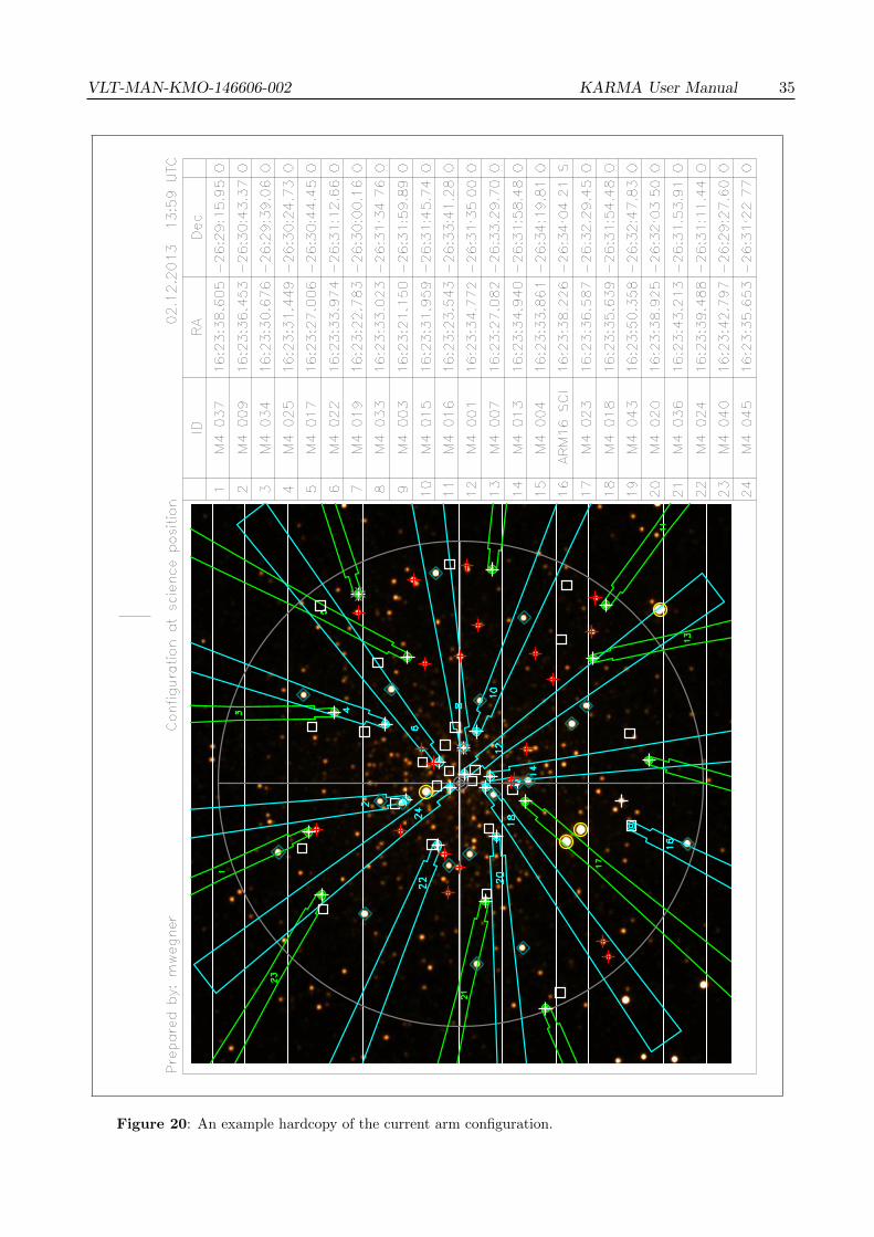
VLT-MAN-KMO-146606-002 KARMA User Manual 35
Figure 20: An example hardcopy of the current arm configuration.
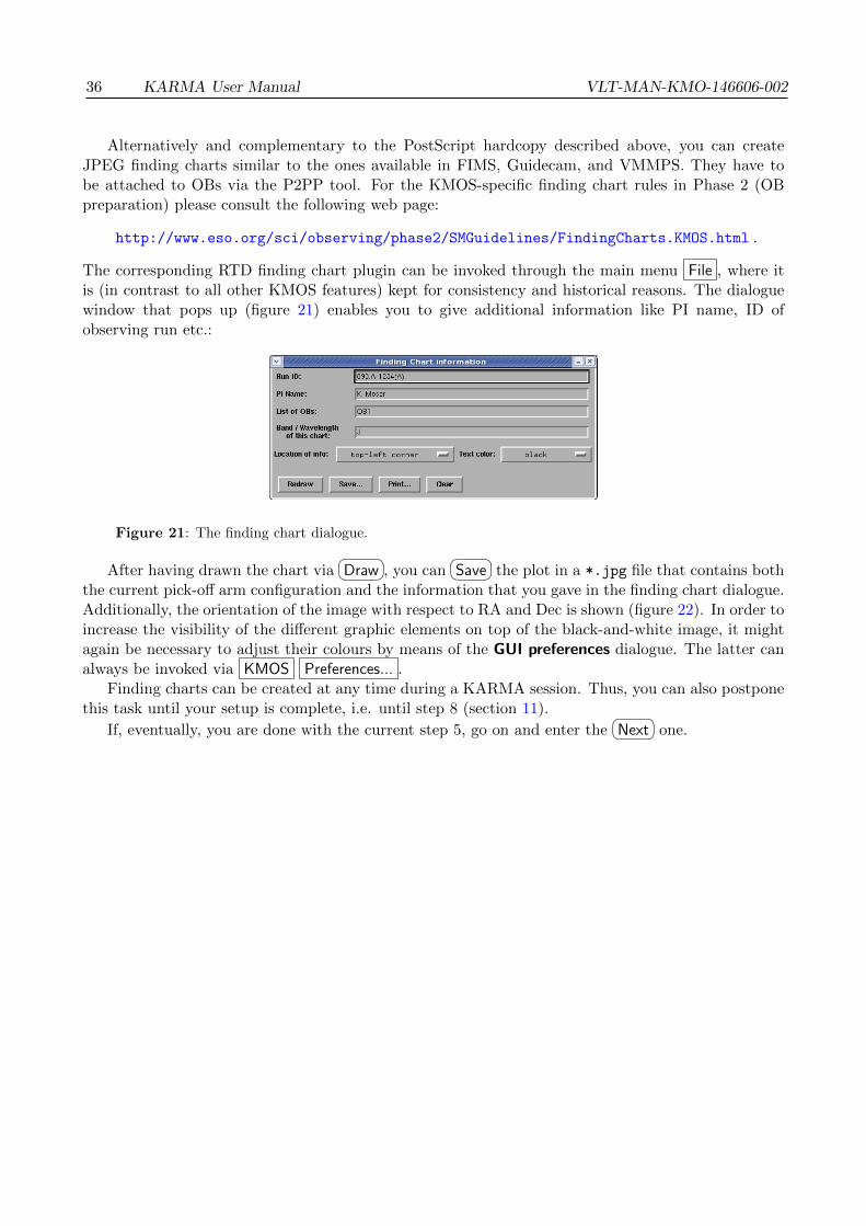
36 KARMA User Manual VLT-MAN-KMO-146606-002
Alternatively and complementary to the PostScript hardcopy described above, you can createJPEG finding charts similar to the ones available in FIMS, Guidecam, and VMMPS. They have tobe attached to OBs via the P2PP tool. For the KMOS-specific finding chart rules in Phase 2 (OBpreparation) please consult the following web page:
http://www.eso.org/sci/observing/phase2/SMGuidelines/FindingCharts.KMOS.html .
The corresponding RTD finding chart plugin can be invoked through the main menu File , where itis (in contrast to all other KMOS features) kept for consistency and historical reasons. The dialoguewindow that pops up (figure 21) enables you to give additional information like PI name, ID ofobserving run etc.:
Figure 21: The finding chart dialogue.
After having drawn the chart via�� ��Draw , you can
�� ��Save the plot in a *.jpg file that contains boththe current pick-off arm configuration and the information that you gave in the finding chart dialogue.Additionally, the orientation of the image with respect to RA and Dec is shown (figure 22). In order toincrease the visibility of the different graphic elements on top of the black-and-white image, it mightagain be necessary to adjust their colours by means of the GUI preferences dialogue. The latter canalways be invoked via KMOS Preferences... .
Finding charts can be created at any time during a KARMA session. Thus, you can also postponethis task until your setup is complete, i.e. until step 8 (section 11).
If, eventually, you are done with the current step 5, go on and enter the�� ��Next one.

VLT-MAN-KMO-146606-002 KARMA User Manual 37
Figure 22: KARMA finding chart in JPEG. Apart from the current pick-off arm configuration, some
additional information is plotted here. Colours have been adjusted appropriately.

38 KARMA User Manual VLT-MAN-KMO-146606-002
9 Step 6: Define arm configuration for acquisition
This step, if necessary at all (see the subsections below), essentially requires the same actions as thelast one. It is meant for the preparation of a special arm configuration to be used for the alignment oftelescope and instrument (the acquisition) just before the science observation. For this purpose a setof reference targets, preferentially brighter than 14th magnitude in J, shall be observed with a shortexposure time so that the high-level instrument control software can calculate and correct for possibledeviations of the actual from the nominal telescope position and instrument rotator angle. Your taskis to allocate enough arms to the reference targets, which you had provided along with your catalogue.
9.1 Acquisition from science targets
If at least 2 of the science targets allocated during the last step are bright enough to be suitable foracquisition, i.e. if they were marked as ’OR’ in your input catalogue and if they were actually assignedto pick-off arms, everything is fine. No additional action is necessary during observation preparationin this case. KARMA would have detected this and skipped the current step entirely. At the time ofOB execution KMOS will take an acquisition exposure with the pick-off arms already at their finalpositions to be used for the science observation (figure 23). This is the one you prepared in step 5.
Arms configured for Science
Tel
esco
peat
Sky
posi
tion
Tel
esco
peat
Scie
nce
posi
tion
arms onscience targets
arms onsky background
Figure 23: Acquisition from science targets. Some of them (yellow bullets among the red ones) are
suitable as reference targets.
If you now realise that it could have been possible to allocate additional reference targets already inthe previous step, you can always go
�� ��Back and modify your science configuration accordingly. Avoid-ing an extra acquisition configuration and doing the alignment by means of the science configurationis always preferable as it saves valuable observing time.
A special case is the Mosaic mode. Due to its nature it doesn’t need a very accurate positioningof telescope and instrument, and hence it doesn’t require an acquisition step at all. KARMA will skipthe entire step 6 also in this case.

VLT-MAN-KMO-146606-002 KARMA User Manual 39
9.2 Acquisition from reference targets
If none of the cases above applies, you are called upon to specify a dedicated acquisition configuration:
Arms configured for Acquisition Arms configured for ScienceT
eles
cope
atSk
ypo
siti
onT
eles
cope
atA
cqui
siti
onpo
siti
on
Tel
esco
peat
Sky
posi
tion
Tel
esco
peat
Scie
nce
posi
tion
arms onreference targets
arms onsky background
arms onscience targets
arms onsky background
Figure 24: Acquisition from reference targets. Two additional telescope positions (left) complement
the already defined ones for the science observation (right).
During OB execution, KMOS will then allocate the arms you have specified to the correspondingreference targets, telescope and instrument will be aligned for this configuration. Then the arms willbe retracted again and finally deployed to their science positions.
To accomplish this preparation task, KARMA provides the same control panel page as in step 5.Again, you have to define the telescope position and instrument rotator angle first by means of thededicated button panel in the upper part. The default position is now the one you have defined inthe previous step for the science configuration. If there are enough reference targets (symbolised bythe diamonds of whatever colour) within the field of view, you don’t need to change it. At least 2
of them are required. Allocate reference targets with a method of your choice by�� ��Allocate and, if
necessary,�� ��Reset . The statistics frame again shows the result. Don’t bother about the science target
allocations which may possibly be counted simultaneously. They belong to the catalogue entriesmarked as ’OR’. Anyway, the IFU windows on the right side of the main window should prove thatthe targets you allocate are really bright: Depending on the setting of the cut levels, usually the wholewindow is oversaturated (figure 25, bottom). Don’t care about this, it’s only the display and/or thepoor resolution of the M4 example image.
Regarding the sky position, it is in contrast to the previous step not really necessary to specifyone. A default offset of 10 arcsec in direction of increasing Dec and with respect to the �Acquisition A
position is already predefined. It provides for a blind telescope offset during the actual acquisition andshould be sufficient in terms of data reduction since the reference targets are bright enough comparedto background signal. Although it doesn’t need to be defined explicitly (but you can do it), the sky
position is nevertheless required to be fixed in the �Sky A tab. Then, go to the�� ��Next step.

40 KARMA User Manual VLT-MAN-KMO-146606-002
Figure 25: Top: Control panel before and after having performed telescope/instrument adjustment
and arm allocation in a dedicated acquisition preparation step. Bottom: Main window after automatic
allocation of reference targets.

VLT-MAN-KMO-146606-002 KARMA User Manual 41
10 Step 7: Select telescope guide stars
During your observation the telescope will be guided by means of the telescope guide probe, whichkeeps a previously selected star centred all the time. To provide a set of coordinates for stars brightenough (brighter than 12th magnitude in R), as well as otherwise suitable for this purpose (particularly,they should be corrected for proper motion), is your task. Although the final selection of the actuallyused guide star will be made by the night time operator at Paranal, you must specify a set of upto 5 potential ones already now. The upper limit of 5 is given by the Telescope Control Software.Fortunately, you have (hopefully) defined quite a few of them in your KARMA catalogue (remembersection 4). You can, however, quickly verify that not all of them are available anymore. Just havea look at the main window (figure 26). All the still existing symbols indicating a potential guide
Figure 26: The main window ready for telescope guide star selection. The translucent area depicts
the guide star avoidance zone.
star – the saltires of whatever colour – are located outside a certain avoidance zone, indicated by atranslucent shading. The reason for this is the finite size of the guide probe, which shall not be allowedto vignet parts of the KMOS field during guiding. For the same reason the guide star selection taskappears so late in the sequence of preparation steps: The actual position of the KMOS FoV in all 4telescope pointings is known only now when the allocation task is already done. See figure 27.
Here, the four red circles indicate the KMOS FoV at science, sky, acquisition and acquisition sky
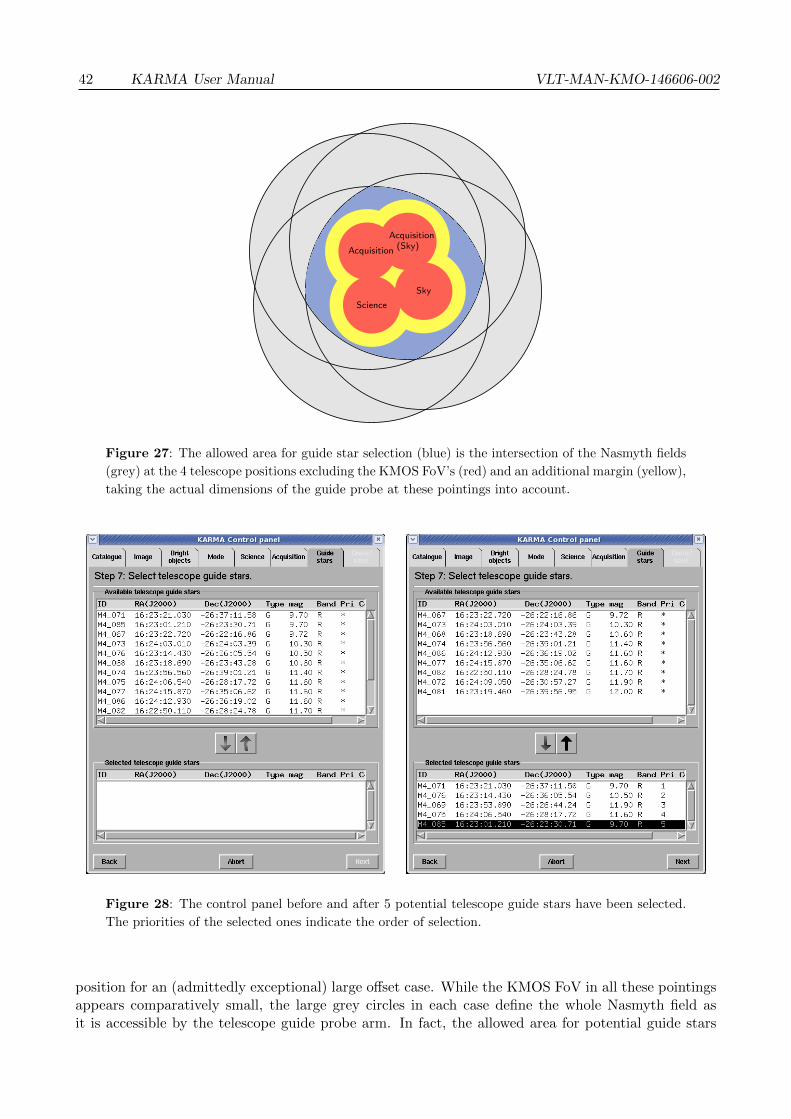
42 KARMA User Manual VLT-MAN-KMO-146606-002
Acquisition(Sky)Acquisition
ScienceSky
Figure 27: The allowed area for guide star selection (blue) is the intersection of the Nasmyth fields
(grey) at the 4 telescope positions excluding the KMOS FoV’s (red) and an additional margin (yellow),
taking the actual dimensions of the guide probe at these pointings into account.
Figure 28: The control panel before and after 5 potential telescope guide stars have been selected.
The priorities of the selected ones indicate the order of selection.
position for an (admittedly exceptional) large offset case. While the KMOS FoV in all these pointingsappears comparatively small, the large grey circles in each case define the whole Nasmyth field asit is accessible by the telescope guide probe arm. In fact, the allowed area for potential guide stars
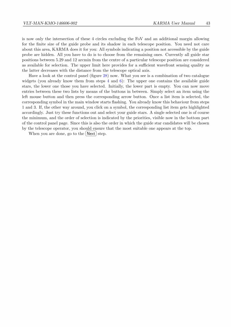
VLT-MAN-KMO-146606-002 KARMA User Manual 43
is now only the intersection of these 4 circles excluding the FoV and an additional margin allowingfor the finite size of the guide probe and its shadow in each telescope position. You need not careabout this area, KARMA does it for you: All symbols indicating a position not accessible by the guideprobe are hidden. All you have to do is to choose from the remaining ones. Currently all guide starpositions between 5.29 and 12 arcmin from the centre of a particular telescope position are consideredas available for selection. The upper limit here provides for a sufficient wavefront sensing quality asthe latter decreases with the distance from the telescope optical axis.
Have a look at the control panel (figure 28) now. What you see is a combination of two cataloguewidgets (you already know them from steps 4 and 6): The upper one contains the available guidestars, the lower one those you have selected. Initially, the lower part is empty. You can now moveentries between these two lists by means of the buttons in between. Simply select an item using theleft mouse button and then press the corresponding arrow button. Once a list item is selected, thecorresponding symbol in the main window starts flashing. You already know this behaviour from steps1 and 3. If, the other way around, you click on a symbol, the corresponding list item gets highlightedaccordingly. Just try these functions out and select your guide stars. A single selected one is of coursethe minimum, and the order of selection is indicated by the priorities, visible now in the bottom partof the control panel page. Since this is also the order in which the guide star candidates will be chosenby the telescope operator, you should ensure that the most suitable one appears at the top.
When you are done, go to the�� ��Next step.

44 KARMA User Manual VLT-MAN-KMO-146606-002
11 Step 8: Save configuration (PAF) file
Now that you have almost completed your work, it’s time to have a final look at what you haveaccomplished. For this purpose the control panel (figure 29) gives you the opportunity to examinethe pick-off arm configurations again and to check whether everything appears as it was intended. Ifnot, you have always the possibility to go
�� ��Back to the appropriate steps where you can correct yourpreviously made allocations and/or other settings. In addition, you have access to all previous stepsby means of the tabs at the top of the control panel, but you can change only a few things in this way.In the current step, i.e. via the current control panel page, you can check all the 4 telescope positions
Figure 29: Summary of the arm allocations in the 4 telescope positions. After having finished a
KARMA cycle the control panel offers the possibility to check these configurations and to save them
as PAF file (left : before, right : after the PAF file was saved).
and the corresponding pick-off arm configurations you have defined during steps 5 and 6. The controlpanel offers you 4 more tabs, each of which giving access to a table with 24 rows for the 24 pick-offarms. Each of these rows in turn summarises the most important settings for the arm it is related to:
• The ID of the target which the arm is assigned to. For artificial sky positions (those createdautomatically during allocation in contrast to the ones already present in the KARMA inputcatalogue) the ID is ARM<i> (1 ≤ i ≤ 24) with suffix SCI, SKY, ACQ or SKA.
• The celestial position (right ascension and declination).
• The type of the target (O for science, R for reference and S for sky targets).
• The priority of the assigned target.
• The comment from the KARMA catalogue (if existing).
Rows corresponding to free or locked arms remain empty. The arm button in front of each rowhighlights the corresponding pick-off arm in the main window.

VLT-MAN-KMO-146606-002 KARMA User Manual 45
You can switch between the tabs: The main window then will show the corresponding arm config-uration in the appropriate telescope position. If step 6 was omitted because the acquisition is possiblefrom science targets alone or if you are going to observe in Mosaic mode, the �Acquisition A tab con-
tains the same information as the �Science A tab. The same applies to the dedicated sky position tobe used in acquisition: If you don’t have specified any, the default position will be displayed.
At this point you have, by the way, again (and for the last time) occasion to create your findingcharts. Just switch to the tab whose configuration you are going to plot, invoke the finding chartplugin via the File menu,
�� ��Draw and�� ��Save the JPEG file(s).
Once you are happy with your setup, you can now finalise your current KARMA cycle by creatingthe PAF file that shall be appended to the OB later on. Use the
�� ��Save... button for this purpose. Thestandard file dialogue that pops up already suggests you a file name containing the date of creationand the observation mode. You need not adhere to this default suggestion and can choose whateverfile name you like (the extension *.ins, however, is mandatory). But since in the P2PP tool youwill later have to select the proper observation template according to the mode you have chosen instep 4, it is strongly recommended to include the appropriate information already in the PAF filename. Please note also that this name is written into the file itself and will appear in the P2PP GUIexactly as it was chosen initially, regardless of whether you rename the file later on. It is thereforenot recommended (but not forbidden) to change the names of PAF files afterwards.
�� ��Save... your filenow. As it is plain ASCII, you might want to have a look at it and check again if everything lookswell. You should, however, refrain from editing the file in any way. The P2PP tool will not accept itin this case because of a wrong checksum.
In Mosaic mode it may happen that several PAF files (up to 4) are created automatically accordingto the size of the contiguous field you have selected in step 4. The file name(s) then contain the positionwithin the Mosaic super field through an additional index. See section 7 for reference.
Now, having created a PAF file and possibly one or more finding charts, in principle you are donewith KARMA. You could choose to
�� ��Finish , then exit RTD and continue preparing your OB(s) withthe P2PP tool. The usage of the latter where you will need the just created file as well as you mustremember the observation mode, is beyond the scope of this manual. See the P2PP manual [3] forthis purpose.
If you want to recheck again whether everything is well with your PAF file(s) before using theP2PP tool, you can6 reload your file(s) into KARMA after having finished the current session. Do
this by means of KMOS Load PAF... (see next section 12 for more details). In case of severe defects(wrong checksum, missing/additional string quotes etc.), KARMA rejects the file and indicates thatsomething went wrong.
For the time being, however, if there are remaining targets in your catalogue to be allocated in afurther step, you can run through a second KARMA pass and do the steps from 4 to 8 all over again.If this is the case, you need not do this instantaneously. Instead, you can save the current state of yourKARMA session by means of the main menu item KMOS Save XML... : It conserves all availablesettings in a proprietary XML file so that you can resume work later on exactly at the point you havereached now. You can, by the way, do this whenever you want. The next section tells you more aboutthe options you have. It also explains why you end up in step 4 if you choose
�� ��Next now.
6Better: You should... It is strongly recommended.

46 KARMA User Manual VLT-MAN-KMO-146606-002
12 It’s not over until it’s over
If you now still haven’t given up although the KARMA preparation process came to a preliminaryend, you find yourself in step 4 again after having pressed
�� ��Next at the end of the last step. Thiswill usually be the case if your catalogue contains more than 24 targets. Then you have to createmore than a single OB, and you will prepare further PAF files with a similar sequence of actionsas described in the last sections. The right part of figure 30 illustrates the transitions between thedifferent preparation steps.
START
END
RTD modeentry / do nothingexit / clear imagedo / handle user input
KARMA modeentry / open control panelexit / close control paneldo / handle user input
New
Abort
Main window closed
LoadXM
L
LoadPAF
Step 1: Load catalogue
Step 2: Load image
Step 3: Identify bright objects
Step 4: Choose observing mode
Step 5: Define science configuration
Step 6: Define acquisition configuration
Step 7: Select telescope guide stars
Step 8: Check + save configuration
Next Back
Next Back
Next Back
Next Back
Next [acquisitionfrom reference] Back
NextBack [acquisitionfrom reference]
Next Back
Nex
t[a
cqui
siti
onfr
omsc
ienc
e/M
osai
c]
Bac
k[a
cqui
siti
onfr
omsc
ienc
e/M
osai
c]N
ext
Figure 30: State chart illustrating the different ways to start and finish a KARMA session and
to switch between RTD and KARMA mode, respectively. On the right hand side the sequence of
preparation steps is shown as substates of the KARMA mode.
Why does the cycle now doesn’t start with step 1 again? It is simply not necessary. Your KARMAinput catalogue already exists, it is loaded and, most important, it is modified according to the actionsyou have performed during the previous KARMA cycle. It makes no sense to start again from thevery beginning. For the same reason you need not (and are not allowed to) load another image orspecify the bright objects again. The cycle as it now starts with the selection of a suitable observationmode, however, can be repeated as long as you want.
If you now have a look at the main window, you recognise that the already allocated targets havedisappeared and only the remaining targets are still displayed. The other ones have been removedfrom the internal copy of the catalogue. Furthermore, all potential telescope guide stars are availableagain for selection, the formerly allocated reference targets are displayed as “free”. Even in case therearen’t any not allocated science targets anymore, KARMA doesn’t stop because you could be goingto use the Mosaic mode.
In this way you can in principle run through the KARMA cycle again and again and prepare asmany PAF files as you want. But you need not necessarily do this instantaneously. In case yourcatalogue is too large to finish all PAF files during a single session, it is possible to interrupt KARMA

VLT-MAN-KMO-146606-002 KARMA User Manual 47
work and to resume it later on. Provided that you have saved the current state of your KARMA sessionby means of KMOS Save XML... at the end of the last step, you can at any time continue just at
this point if you start a new KARMA session with KMOS Load XML... via the main window menu.Furthermore, in the exceptional case of a computer crash you can recover your KARMA session froma temporary XML backup file, which is stored under .karma in your home directory. It is, however,of temporary nature and will be deleted when you leave KARMA.
Only if you feel you are really ready, you can exit KARMA either by�� ��Finish from the control
panel or via the main menu by KMOS Abort . You then end up in the “normal” RTD mode (seefigure 30). If you close the main window, you leave KARMA and RTD irrevocably.
But that’s not all, there is yet another possibility to restore a KARMA session. The option KMOS
Load PAF... is intended for the night time operator at Paranal to check whether the telescope and/orinstrument behave as the astronomer wanted them to behave. It recreates only those settings whichwere finally stored in the PAF file, namely the arm configurations, the selected guide stars (not allfrom the catalogue), the telescope positions and the bright object list. All other settings, particularlythe remaining science and reference targets from the catalogue, are lost. Furthermore, it is not possibleto change such a reloaded configuration.
As already mentioned in the last section, you should check anyway whether everything went wellwith your observation preparation by loading your own just created PAF file into KARMA again. Youshould do this particularly if you have transferred the file by e-mail or if you have moved it betweendifferent operating sytems. KARMA can check then for possible defects and, to a limited extent, givesyou the opportunity to repair a corrupted file. If the latter, for example, contains DOS-like carriagereturns (see also the recommendation in section 4), KARMA issues an appropriate warning through a
dedicated message dialogue. You can either�� ��Discard the file here, leaving it unchanged (and probably
corrupt), or you can force the PAF loading via the�� ��Repair button. You only have to save it again
then through the corresponding control panel page (the one dedicated to step 8), the original file willremain unchanged unless you overwrite it deliberately. The same applies to (for whatever reason)
wrong check sums. They will be corrected if you�� ��Save ... the PAF file again7
Finally, with KMOS New you always start a completely new KARMA session. It would lead youagain to step 1 and section 4, respectively. At this point, however, you have reached the end of theKARMA User manual. We hope you could benefit from it and wish you good luck with your KMOSobservations.
7 Due to a bug in a previous KARMA release, the guide star numbering in PAF files created before version 2.2 mightbe wrong, i.e. selected guide stars might have numbers lower than 1 or greater than 5. This can be corrected in thesame way: Reload the PAF file and save it again.

48 KARMA User Manual VLT-MAN-KMO-146606-002
A Frequently asked questions
1. Q: Why are there so many different tools: Exposure Time Calculator, P2PP, KARMA?A: For practical and historical reasons. The Exposure Time Calculator (ETC), for instance, isusually already required during Phase 1 when a proper evaluation of the required observationtime must be made. The P2PP tool on its part is necessary only if the proposal from Phase 1 isaccepted. Furthermore, the latter was initially designed to specify simple observation parametersfor simple instruments only. For rather complex ones these capabilities are not sufficient anymorebut must be complemented by additional utilities while the classic P2PP tool still represents thelowest common denominator for all instruments.
2. Q: Is there any KARMA version for Mac OS or Windows?A: At the moment there exists a single binary for Mac OS X for an i386 hardware, but withoutany warranty for portability. Please consult the following ESO webpage for information aboutthe supported platforms and available binary versions:
http://www.eso.org/sci/observing/phase2/SMGuidelines/KARMAInstall.html
Regardless of that, a KARMA for Windows/Vista will probably never exist for technical reasons.
3. Q: When I try to build it from the source package, KARMA complains about a missing library.Where can I get the required one?A: First, check if one of the pre-compiled KARMA binary packages might possibly be suitablefor you. If not, search via your Linux package manager (for example the RPM one that is usedin many GNU/Linux distributions) for the missing library and, if not yet installed, install it.The static stdc++ library can, for instance, usually be found as package libstdc++-static orlibstdc++6<version>-dev. In general, KARMA is designed in such a way that only a minimumof possibly platform-dependent prerequisites are necessary.
4. Q: Why can’t I use the intrinsic Skycat/RTD feature XY while I’m in KARMA mode?A: To avoid the possibility of getting confused by too many features in too many open windows,the RTD functionality available in KARMA mode was restricted to the absolute minimum. Allyou really need is available through the central KARMA control dialogue. If you want to use acertain RTD/Skycat feature, abort the KARMA session and switch back to RTD mode.
5. Q: Why isn’t it possible to optimise the total allocation efficiency over multiple KARMA cyclesautomatically in case the KARMA catalogue contains more than 24 targets?A: In each cycle the allocation task depends on the chosen telescope pointing and the instru-ment rotator angle. Allowing for both of these (continuously adjustable) free parameters in anallocation algorithm would introduce too many additional degrees of freedom. But even if such ahuge complexity were manageable: The sky background position complementing a certain targetallocation can be obtained only interactively and hence cannot be part of an automatic algorithm.
6. Q: KARMA complains that my catalogue contains “DOS-like carriage returns”. How could thishappen, and what shall I do now?A: Different operating systems have different conventions of how line endings in ASCII files arerepresented. All Unix-like systems (including GNU/Linux and Mac OS X) use a single line feed(LF, ’\n’) only. This is also the expected line ending for catalogue files in KARMA. On Windows-like systems (including MS-DOS, Microsoft Windows, Vista etc.), however, a combination of aline feed and a carriage return (CR, ’\r’) is used. You need not necessarily have preparedyour catalogue on such a system, it is sufficient to have sent it by email as an attachment via aWindows mail server and/or relay. Text files are usually converted into the format that followsthe convention on the server then. If one or the other case happens to you, you can use the

VLT-MAN-KMO-146606-002 KARMA User Manual 49
catalogue anyway, but you have to confirm the loading after KARMA has issued an appropriatewarning. If possible, however, you should try to avoid such cases and prepare your catalogue ona native Unix-like system.
7. Q: Why isn’t it possible to define new targets by means of the image?A: Since KMOS has no imaging mode, there can be no reasonable restriction regarding the sourceof an image to be used in KARMA. The accuracy of target positions obtained from such an image,however, would strongly depend on its astrometric properties and possibly be different from theaccuracy of other catalogue entries. The positioning errors arising from such discrepancies arevery difficult to detect, and therefore they shall be ruled out by design.
8. Q: Shouldn’t it be impossible to mark a single catalogue entry as science target and potentialguide star at the same time?A: Whether a certain catalogue entry can become a potential guide star can be decided onlywhen the science target allocations are made and the position of the KMOS field of view withrespect to the catalogue field is fixed. This happens during the KARMA session, not before.Then, of course, a guide star cannot serve as a science target anymore since guide stars must lieoutside the field of view. The same applies the other way around.
9. Q: Why do you need to specify the telescope position in KARMA if this is already a P2PPparameter?A: The telescope pointings are specified by the target field centre and your chosen sky backgroundposition, respectively. While the former is usually chosen with special focus on the most efficienttarget allocation, the latter must be determined interactively after having already assigned thepick-off arms. Since both tasks depend on the allocation process itself, they can only performedwith KARMA. The initial telescope pointing (the one for acquisition), however, will be transferredto the P2PP tool automatically and must not be modified/edited in the OB.
10. Q: Why can’t I get two arms closer to each other although they don’t seem to touch yet?A: To allow for additional small pick-off arm displacements (at observation time) due to cor-rections of differential atmospheric refraction effects each arm is surrounded by a small “safetymargin” which defines the closest possible approach of 2 arms in KARMA.
11. Q: Why do I need a dedicated sky background position for the acquisition, even in case it is doneby means of bright reference stars?A: Reference objects need not necessarily to be as bright as it is required by data reductionto determine their centre position exactly. As a precaution for such cases the additional skybackground (position) must be provided.
12. Q: Why do I get a warning that a particular bottom arm IFU is vignetted? Even with the largestpossible zoom I can’t see any neighbouring upper arm shadowing it.A: The IFU size as drawn by KARMA is the one related to the focal plane. The arms, however,are actually located above and below it. Therefore their tip mirrors see a somewhat divergedbeam and partial vignetting can occur even in cases when it seems not to be so. In other words:The shadow of an upper arm is larger than its outline drawn by KARMA suggests. KARMAtakes this effect into account.
13. Q: Does the exact position of a manually allocated arm depend on the accuracy of its manualplacement in the KARMA main window and because of that possibly even on the screen resolu-tion?A: No. If you got the tip centre close enough to the envisaged target, KARMA detects a sufficientproximity at allocation time (i.e. when you press
�� ��Allocate ) and gives the arm the exact targetposition as it appears in the catalogue. Depending on the screen resolution and the zoom settings

50 KARMA User Manual VLT-MAN-KMO-146606-002
also a slight shift of the arm outline may be visible. Either way, you recognize that an allocationwas successful by means of the changed symbol colour of the assigned target.
14. Q: There is no guide star available for selection anymore although I have specified quite a few inthe input catalogue. What can I do?A: In this case all your potential guide stars are located within the avoidance zone, consistingof the KMOS FoV’s at the 4 telescope positions and an additional margin allowing for the finitesize of the guide probe. You can either modify the telescope pointings (large offsets betweenscience/acquisition and sky positions increase the avoidance zone, so you can try to decrease theoffsets) or you can supply additional guide stars with a modified input catalogue. In both cases,whether you like it or not, you have to go back to the corresponding preparation step.
15. Q: The telescope position that I find in the PAF file (TEL.TARG.ALPHA and TEL.TARG.DELTA) inMosaic mode is different from my catalogue centre although I didn’t apply any offsets in KARMA.Why?A: Although an observation in Mosaic mode consists of a series of exposures at different telescopepositions, only the first pointing appears in the PAF file. As the execution of a Mosaic OB alwaysstarts at the upper left corner of the mapping area, the telescope position in the PAF file is thusthe one that aligns the upper left IFU of the fixed arm configuration (see figure 15) with thiscorner. For the large Mosaic pattern this requires an offset of about 4.05 arcsec in both directionsfrom the centre of the mapping area.
16. Q: Why isn’t it possible to restore a previously abandoned KARMA session from the PAF filealone?A: The PAF file is the one which goes into the OB. Therefore only that information is includedthere which is absolutely necessary to carry out the observation. The KARMA session state,however, includes much more information to store: All not yet allocated targets, for example,not used guide stars, actual settings of the user interface and much more. All this additionalinformation would require additional keywords and pollute the PAF file unnecessarily.
17. Q: Is it possible to edit the PAF file manually after it has been generated?A: According to Radio Yerevan (http://en.wikipedia.org/wiki/Radio_Yerevan_jokes): Inprinciple, yes. But your file will be corrupted then because the automatically generated checksumdoesn’t match the content anymore. Although KARMA can repair the file, you possibly run intoother problems. So, don’t do that – editing the PAF file is evil!
18. Q: What happens if a certain hardware component (a pick-off arm or grating, for example) getsbroken between the submission of my OB and the actual observation? Are the correspondingtarget allocations lost?A: Shit happens. Depending on the type and number of broken components the correspondingpick-off arms will be locked and are not available for observation anymore. However, there willalways be an attempt to keep the most important target allocations also in case of such a hardwarefailure. For this purpose the rotational position of the instrument will be optimised just beforethe OB execution so that a maximum of priority 1 targets can be observed with the then stillavailable arms.

VLT-MAN-KMO-146606-002 KARMA User Manual 51
B Example catalogue
#------------------------------------------------------------------------------
# M4.cat
#
# Prepared: Michael Wegner (using the 2MASS catalogue)
# Last modified: 2013-11-17
#
# All entries were retrieved from the 2MASS All-Sky Point Source Catalog (PSC).
# The following arbitrary limits (without any scientific justification) have
# been chosen for this particular example:
# 9.2 < Jmag <= 10.55 for science targets
# 8.0 < Jmag <= 9.20 for reference targets
# Jmag <= 8.00 for bright objects
# Jmag > 10.55 for marker positions
# Rmag <= 12.00 for guide stars (mag of associated optical sources)
# These settings ensure a sufficient visibility of the targets/objects on the
# corresponding background image taken from the 2MASS image server as well as
# a reasonable entry number for each type.
# For the sake of simplicity the priorities of all science and reference tar-
# gets were set to 1.
#------------------------------------------------------------------------------
# ID RA(J2000) Dec(J2000) Type mag Band Pri Comment
#------------------------------------------------------------------------------
M4_000 16:23:35.410 -26:31:31.90 C * * * field centre of M4
M4_001 16:23:34.772 -26:31:35.00 O 10.21 J 1
M4_002 16:23:23.058 -26:33:32.26 O 10.32 J 1
M4_003 16:23:21.150 -26:31:59.89 O 10.45 J 1
M4_004 16:23:33.861 -26:34:19.81 O 9.72 J 1
M4_005 16:23:28.460 -26:32:54.14 O 10.41 J 1
M4_006 16:23:33.130 -26:30:56.88 O 10.14 J 1
M4_007 16:23:27.082 -26:33:29.70 O 10.54 J 1
M4_008 16:23:26.942 -26:31:31.32 O 9.51 J 1
M4_009 16:23:36.453 -26:30:43.37 O 9.98 J 1
M4_010 16:23:38.571 -26:30:38.07 O 10.16 J 1
M4_011 16:23:20.899 -26:31:36.88 O 10.54 J 1
M4_012 16:23:27.418 -26:30:59.56 O 10.23 J 1
M4_013 16:23:34.940 -26:31:58.48 O 10.54 J 1
M4_014 16:23:40.986 -26:31:30.20 O 9.92 J 1
M4_015 16:23:31.959 -26:31:45.74 O 10.35 J 1
M4_016 16:23:23.543 -26:33:41.28 O 10.29 J 1
M4_017 16:23:27.006 -26:30:44.45 O 10.59 J 1
M4_018 16:23:35.639 -26:31:54.48 O 9.87 J 1
M4_019 16:23:22.783 -26:30:00.16 OM 10.56 * * marker position
M4_020 16:23:38.925 -26:32:03.50 O 10.46 J 1
M4_021 16:23:26.749 -26:32:38.85 O 10.47 J 1
M4_022 16:23:33.974 -26:31:12.66 O 10.53 J 1
M4_023 16:23:36.587 -26:32:29.45 O 10.54 J 1
M4_024 16:23:39.488 -26:31:11.44 O 9.86 J 1
M4_025 16:23:31.449 -26:30:24.73 O 9.58 J 1

52 KARMA User Manual VLT-MAN-KMO-146606-002
M4_026 16:23:45.926 -26:33:38.94 O 10.10 J 1
M4_027 16:23:36.534 -26:33:55.34 O 10.20 J 1
M4_028 16:23:25.304 -26:33:29.19 O 9.91 J 1
M4_029 16:23:33.105 -26:32:30.63 O 10.29 J 1
M4_030 16:23:21.846 -26:30:49.55 O 9.76 J 1
M4_031 16:23:24.884 -26:31:47.46 O 10.16 J 1
M4_032 16:23:40.111 -26:31:17.20 O 9.54 J 1
M4_033 16:23:33.023 -26:31:34.76 OM 10.58 * * marker position
M4_034 16:23:30.676 -26:29:39.06 O 9.96 J 1
M4_035 16:23:42.688 -26:31:20.91 O 10.25 J 1
M4_036 16:23:43.213 -26:31:53.91 O 9.96 J 1
M4_037 16:23:38.605 -26:29:15.95 O 10.46 J 1
M4_038 16:23:34.021 -26:31:07.77 O 10.07 J 1
M4_039 16:23:35.304 -26:32:16.62 O 10.16 J 1
M4_040 16:23:42.797 -26:29:27.60 O 9.82 J 1
M4_041 16:23:35.110 -26:32:19.99 O 9.55 J 1
M4_042 16:23:38.469 -26:29:23.52 O 9.66 J 1
M4_043 16:23:50.358 -26:32:47.83 O 9.92 J 1
M4_044 16:23:24.021 -26:30:00.53 O 9.89 J 1
M4_045 16:23:35.653 -26:31:22.77 O 9.68 J 1
M4_046 16:23:46.923 -26:33:43.91 O 10.14 J 1
M4_047 16:23:21.398 -26:31:09.39 R 8.81 J 1
M4_048 16:23:24.374 -26:32:28.49 R 9.44 J 1
M4_049 16:23:36.144 -26:32:01.59 R 8.88 J 1
M4_050 16:23:31.427 -26:33:11.04 R 8.63 J 1
M4_051 16:23:29.510 -26:29:11.63 R 9.32 J 1
M4_052 16:23:39.398 -26:34:54.33 R 8.46 J 1
M4_053 16:23:36.577 -26:30:20.04 R 9.35 J 1
M4_054 16:23:35.355 -26:32:22.53 R 8.75 J 1
M4_055 16:23:40.856 -26:31:21.56 R 9.31 J 1
M4_056 16:23:44.054 -26:30:06.14 R 8.77 J 1
M4_057 16:23:29.880 -26:31:49.01 R 9.11 J 1
M4_058 16:23:29.124 -26:30:29.76 R 8.59 J 1
M4_059 16:23:46.323 -26:32:27.24 R 9.19 J 1
M4_060 16:23:47.404 -26:31:46.39 R 8.92 J 1
M4_061 16:23:40.101 -26:31:39.77 R 8.71 J 1
M4_062 16:23:39.969 -26:28:49.08 R 8.61 J 1
M4_063 16:23:30.207 -26:33:24.13 R 9.25 J 1
M4_064 16:23:36.672 -26:30:39.78 R 8.82 J 1
M4_065 16:23:35.200 -26:32:32.33 R 8.83 J 1
M4_066 16:23:30.560 -26:34:17.99 G 11.70 R *
M4_067 16:23:22.720 -26:22:16.86 G 9.72 R *
M4_068 16:23:18.690 -26:23:43.28 G 10.60 R *
M4_069 16:23:53.890 -26:26:44.24 G 11.90 R *
M4_070 16:23:15.780 -26:30:03.69 G 11.80 R *
M4_071 16:23:21.030 -26:37:11.58 G 9.70 R *
M4_072 16:24:09.050 -26:30:57.27 G 11.90 R *
M4_073 16:24:03.010 -26:24:03.39 G 10.30 R *
M4_074 16:23:56.560 -26:39:01.21 G 11.40 R *
M4_075 16:24:06.540 -26:28:17.72 G 11.60 R *

VLT-MAN-KMO-146606-002 KARMA User Manual 53
M4_076 16:23:14.430 -26:36:05.54 G 10.50 R *
M4_077 16:24:15.870 -26:35:06.62 G 11.60 R *
M4_078 16:23:23.710 -26:31:03.44 G 9.60 R *
M4_079 16:23:19.190 -26:33:50.59 G 11.20 R *
M4_080 16:23:43.150 -26:27:16.37 G 11.80 R *
M4_081 16:23:19.460 -26:39:56.95 G 12.00 R *
M4_082 16:22:50.110 -26:28:24.78 G 11.70 R *
M4_083 16:23:48.800 -26:35:09.33 G 11.70 R *
M4_084 16:23:32.450 -26:26:45.79 G 10.30 R *
M4_085 16:23:01.210 -26:23:30.71 G 9.70 R *
M4_086 16:24:12.930 -26:36:19.02 G 11.60 R *
M4_087 16:23:23.819 -26:34:29.76 B 7.01 J *
M4_088 16:23:38.470 -26:33:19.25 B 6.97 J *
M4_089 16:23:35.942 -26:31:00.90 B 7.51 J *
M4_090 16:23:39.274 -26:33:05.97 B 6.97 J *
#------------------------------------------------------------------------------
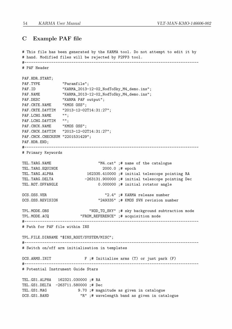
54 KARMA User Manual VLT-MAN-KMO-146606-002
C Example PAF file
# This file has been generated by the KARMA tool. Do not attempt to edit it by
# hand. Modified files will be rejected by P2PP3 tool.
#------------------------------------------------------------------------------
# PAF Header
PAF.HDR.START;
PAF.TYPE "Paramfile";
PAF.ID "KARMA_2013-12-02_NodToSky_M4_demo.ins";
PAF.NAME "KARMA_2013-12-02_NodToSky_M4_demo.ins";
PAF.DESC "KARMA PAF output";
PAF.CRTE.NAME "KMOS OSS";
PAF.CRTE.DAYTIM "2013-12-02T14:31:27";
PAF.LCHG.NAME "";
PAF.LCHG.DAYTIM "";
PAF.CHCK.NAME "KMOS OSS";
PAF.CHCK.DAYTIM "2013-12-02T14:31:27";
PAF.CHCK.CHECKSUM "2201531429";
PAF.HDR.END;
#------------------------------------------------------------------------------
# Primary Keywords
TEL.TARG.NAME "M4.cat" ;# name of the catalogue
TEL.TARG.EQUINOX 2000.0 ;# epoch
TEL.TARG.ALPHA 162335.410000 ;# initial telescope pointing RA
TEL.TARG.DELTA -263131.900000 ;# initial telescope pointing Dec
TEL.ROT.OFFANGLE 0.000000 ;# initial rotator angle
OCS.OSS.VER "2.4" ;# KARMA release number
OCS.OSS.REVISION "249335" ;# KMOS SVN revision number
TPL.MODE.OBS "NOD_TO_SKY" ;# sky background subtraction mode
TPL.MODE.ACQ "FROM_REFERENCE" ;# acquisition mode
#------------------------------------------------------------------------------
# Path for PAF file within INS
TPL.FILE.DIRNAME "$INS_ROOT/SYSTEM/MISC";
#------------------------------------------------------------------------------
# Switch on/off arm initialisation in templates
OCS.ARMS.INIT F ;# Initialise arms (T) or just park (F)
#------------------------------------------------------------------------------
# Potential Instrument Guide Stars
TEL.GS1.ALPHA 162321.030000 ;# RA
TEL.GS1.DELTA -263711.580000 ;# Dec
TEL.GS1.MAG 9.70 ;# magnitude as given in catalogue
OCS.GS1.BAND "R" ;# wavelength band as given in catalogue

VLT-MAN-KMO-146606-002 KARMA User Manual 55
TEL.GS2.ALPHA 162314.430000 ;# RA
TEL.GS2.DELTA -263605.540000 ;# Dec
TEL.GS2.MAG 10.50 ;# magnitude as given in catalogue
OCS.GS2.BAND "R" ;# wavelength band as given in catalogue
TEL.GS3.ALPHA 162353.890000 ;# RA
TEL.GS3.DELTA -262644.240000 ;# Dec
TEL.GS3.MAG 11.90 ;# magnitude as given in catalogue
OCS.GS3.BAND "R" ;# wavelength band as given in catalogue
TEL.GS4.ALPHA 162406.540000 ;# RA
TEL.GS4.DELTA -262817.720000 ;# Dec
TEL.GS4.MAG 11.60 ;# magnitude as given in catalogue
OCS.GS4.BAND "R" ;# wavelength band as given in catalogue
TEL.GS5.ALPHA 162301.210000 ;# RA
TEL.GS5.DELTA -262330.710000 ;# Dec
TEL.GS5.MAG 9.70 ;# magnitude as given in catalogue
OCS.GS5.BAND "R" ;# wavelength band as given in catalogue
#------------------------------------------------------------------------------
# Bright objects in field
OCS.BRGH1.NAME "M4_087" ;# name/id of bright object 1
OCS.BRGH1.ALPHA 162323.819000 ;# RA
OCS.BRGH1.DELTA -263429.760000 ;# Dec
OCS.BRGH1.MAG 7.01 ;# magnitude as given in catalogue
OCS.BRGH1.BAND "J" ;# wavelength band as given in catalogue
OCS.BRGH1.COMMENT "" ;
OCS.BRGH2.NAME "M4_088" ;# name/id of bright object 2
OCS.BRGH2.ALPHA 162338.470000 ;# RA
OCS.BRGH2.DELTA -263319.250000 ;# Dec
OCS.BRGH2.MAG 6.97 ;# magnitude as given in catalogue
OCS.BRGH2.BAND "J" ;# wavelength band as given in catalogue
OCS.BRGH2.COMMENT "" ;
OCS.BRGH3.NAME "M4_089" ;# name/id of bright object 3
OCS.BRGH3.ALPHA 162335.942000 ;# RA
OCS.BRGH3.DELTA -263100.900000 ;# Dec
OCS.BRGH3.MAG 7.51 ;# magnitude as given in catalogue
OCS.BRGH3.BAND "J" ;# wavelength band as given in catalogue
OCS.BRGH3.COMMENT "" ;
OCS.BRGH4.NAME "M4_090" ;# name/id of bright object 4
OCS.BRGH4.ALPHA 162339.274000 ;# RA
OCS.BRGH4.DELTA -263305.970000 ;# Dec
OCS.BRGH4.MAG 6.97 ;# magnitude as given in catalogue
OCS.BRGH4.BAND "J" ;# wavelength band as given in catalogue
OCS.BRGH4.COMMENT "" ;
#------------------------------------------------------------------------------

56 KARMA User Manual VLT-MAN-KMO-146606-002
# Arm configuration at acquisition/target position
OCS.TARG.ACQ.ALPHA 162335.410000 ;# telescope pointing RA
OCS.TARG.ACQ.DELTA -263131.900000 ;# telescope pointing Dec
OCS.ROT.ACQ.OFFANGLE 0.000000 ;# rotator angle
OCS.ARM1.ACQ.NAME "M4_062" ;# name/id of catalogue entry
OCS.ARM1.ACQ.ALPHA 162339.969000 ;# target RA
OCS.ARM1.ACQ.DELTA -262849.080000 ;# target Dec
OCS.ARM1.ACQ.Y 35.888012 ;# y position of arm tip in device system
OCS.ARM1.ACQ.Z 95.459355 ;# z position of arm tip in device system
OCS.ARM1.ACQ.R 168.107181 ;# distance of arm tip from arm axis
OCS.ARM1.ACQ.THETA -1.150209 ;# angular move of arm
OCS.ARM1.ACQ.PRIOR 1 ;# target priority
OCS.ARM1.ACQ.TYPE "R" ;# target type: reference
OCS.ARM1.ACQ.MAG 8.61 ;# magnitude as given in catalogue
OCS.ARM1.ACQ.BAND "J" ;# wavelength band as given in catalogue
OCS.ARM1.ACQ.HIT "" ;# bright object(s) hitting the arm
OCS.ARM1.ACQ.COMMENT "" ;
OCS.ARM3.ACQ.NAME "M4_053" ;# name/id of catalogue entry
OCS.ARM3.ACQ.ALPHA 162336.577000 ;# target RA
OCS.ARM3.ACQ.DELTA -263020.040000 ;# target Dec
OCS.ARM3.ACQ.Y 9.184491 ;# y position of arm tip in device system
OCS.ARM3.ACQ.Z 42.131627 ;# z position of arm tip in device system
OCS.ARM3.ACQ.R 229.892040 ;# distance of arm tip from arm axis
OCS.ARM3.ACQ.THETA 3.642493 ;# angular move of arm
OCS.ARM3.ACQ.PRIOR 1 ;# target priority
OCS.ARM3.ACQ.TYPE "R" ;# target type: reference
OCS.ARM3.ACQ.MAG 9.35 ;# magnitude as given in catalogue
OCS.ARM3.ACQ.BAND "J" ;# wavelength band as given in catalogue
OCS.ARM3.ACQ.HIT "" ;# bright object(s) hitting the arm
OCS.ARM3.ACQ.COMMENT "" ;
OCS.ARM4.ACQ.NAME "M4_064" ;# name/id of catalogue entry
OCS.ARM4.ACQ.ALPHA 162336.672000 ;# target RA
OCS.ARM4.ACQ.DELTA -263039.780000 ;# target Dec
OCS.ARM4.ACQ.Y 9.931683 ;# y position of arm tip in device system
OCS.ARM4.ACQ.Z 30.557958 ;# z position of arm tip in device system
OCS.ARM4.ACQ.R 246.454031 ;# distance of arm tip from arm axis
OCS.ARM4.ACQ.THETA 4.857618 ;# angular move of arm
OCS.ARM4.ACQ.PRIOR 1 ;# target priority
OCS.ARM4.ACQ.TYPE "R" ;# target type: reference
OCS.ARM4.ACQ.MAG 8.82 ;# magnitude as given in catalogue
OCS.ARM4.ACQ.BAND "J" ;# wavelength band as given in catalogue
OCS.ARM4.ACQ.VIGNET F ;# IFU vignetted (T) or not vignetted (F)
OCS.ARM4.ACQ.COMMENT "" ;
OCS.ARM5.ACQ.NAME "M4_051" ;# name/id of catalogue entry
OCS.ARM5.ACQ.ALPHA 162329.510000 ;# target RA
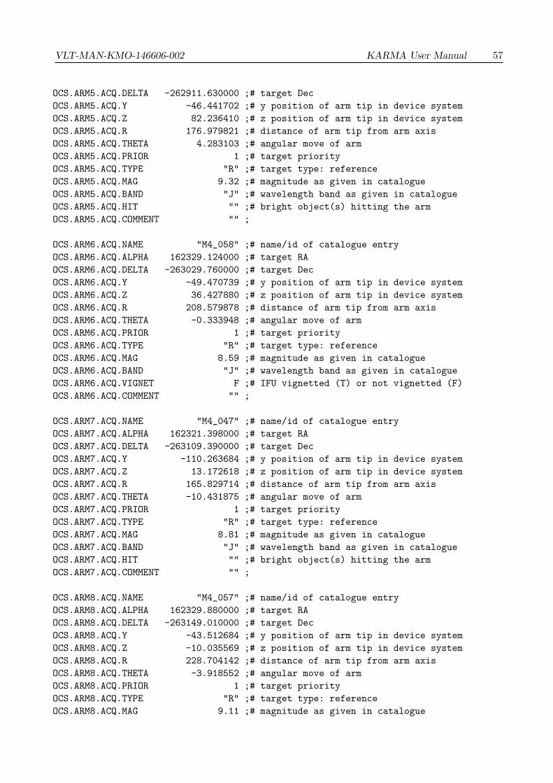
VLT-MAN-KMO-146606-002 KARMA User Manual 57
OCS.ARM5.ACQ.DELTA -262911.630000 ;# target Dec
OCS.ARM5.ACQ.Y -46.441702 ;# y position of arm tip in device system
OCS.ARM5.ACQ.Z 82.236410 ;# z position of arm tip in device system
OCS.ARM5.ACQ.R 176.979821 ;# distance of arm tip from arm axis
OCS.ARM5.ACQ.THETA 4.283103 ;# angular move of arm
OCS.ARM5.ACQ.PRIOR 1 ;# target priority
OCS.ARM5.ACQ.TYPE "R" ;# target type: reference
OCS.ARM5.ACQ.MAG 9.32 ;# magnitude as given in catalogue
OCS.ARM5.ACQ.BAND "J" ;# wavelength band as given in catalogue
OCS.ARM5.ACQ.HIT "" ;# bright object(s) hitting the arm
OCS.ARM5.ACQ.COMMENT "" ;
OCS.ARM6.ACQ.NAME "M4_058" ;# name/id of catalogue entry
OCS.ARM6.ACQ.ALPHA 162329.124000 ;# target RA
OCS.ARM6.ACQ.DELTA -263029.760000 ;# target Dec
OCS.ARM6.ACQ.Y -49.470739 ;# y position of arm tip in device system
OCS.ARM6.ACQ.Z 36.427880 ;# z position of arm tip in device system
OCS.ARM6.ACQ.R 208.579878 ;# distance of arm tip from arm axis
OCS.ARM6.ACQ.THETA -0.333948 ;# angular move of arm
OCS.ARM6.ACQ.PRIOR 1 ;# target priority
OCS.ARM6.ACQ.TYPE "R" ;# target type: reference
OCS.ARM6.ACQ.MAG 8.59 ;# magnitude as given in catalogue
OCS.ARM6.ACQ.BAND "J" ;# wavelength band as given in catalogue
OCS.ARM6.ACQ.VIGNET F ;# IFU vignetted (T) or not vignetted (F)
OCS.ARM6.ACQ.COMMENT "" ;
OCS.ARM7.ACQ.NAME "M4_047" ;# name/id of catalogue entry
OCS.ARM7.ACQ.ALPHA 162321.398000 ;# target RA
OCS.ARM7.ACQ.DELTA -263109.390000 ;# target Dec
OCS.ARM7.ACQ.Y -110.263684 ;# y position of arm tip in device system
OCS.ARM7.ACQ.Z 13.172618 ;# z position of arm tip in device system
OCS.ARM7.ACQ.R 165.829714 ;# distance of arm tip from arm axis
OCS.ARM7.ACQ.THETA -10.431875 ;# angular move of arm
OCS.ARM7.ACQ.PRIOR 1 ;# target priority
OCS.ARM7.ACQ.TYPE "R" ;# target type: reference
OCS.ARM7.ACQ.MAG 8.81 ;# magnitude as given in catalogue
OCS.ARM7.ACQ.BAND "J" ;# wavelength band as given in catalogue
OCS.ARM7.ACQ.HIT "" ;# bright object(s) hitting the arm
OCS.ARM7.ACQ.COMMENT "" ;
OCS.ARM8.ACQ.NAME "M4_057" ;# name/id of catalogue entry
OCS.ARM8.ACQ.ALPHA 162329.880000 ;# target RA
OCS.ARM8.ACQ.DELTA -263149.010000 ;# target Dec
OCS.ARM8.ACQ.Y -43.512684 ;# y position of arm tip in device system
OCS.ARM8.ACQ.Z -10.035569 ;# z position of arm tip in device system
OCS.ARM8.ACQ.R 228.704142 ;# distance of arm tip from arm axis
OCS.ARM8.ACQ.THETA -3.918552 ;# angular move of arm
OCS.ARM8.ACQ.PRIOR 1 ;# target priority
OCS.ARM8.ACQ.TYPE "R" ;# target type: reference
OCS.ARM8.ACQ.MAG 9.11 ;# magnitude as given in catalogue

58 KARMA User Manual VLT-MAN-KMO-146606-002
OCS.ARM8.ACQ.BAND "J" ;# wavelength band as given in catalogue
OCS.ARM8.ACQ.VIGNET F ;# IFU vignetted (T) or not vignetted (F)
OCS.ARM8.ACQ.COMMENT "" ;
OCS.ARM9.ACQ.NAME "M4_048" ;# name/id of catalogue entry
OCS.ARM9.ACQ.ALPHA 162324.374000 ;# target RA
OCS.ARM9.ACQ.DELTA -263228.490000 ;# target Dec
OCS.ARM9.ACQ.Y -86.828227 ;# y position of arm tip in device system
OCS.ARM9.ACQ.Z -33.194509 ;# z position of arm tip in device system
OCS.ARM9.ACQ.R 180.873476 ;# distance of arm tip from arm axis
OCS.ARM9.ACQ.THETA -6.851374 ;# angular move of arm
OCS.ARM9.ACQ.PRIOR 1 ;# target priority
OCS.ARM9.ACQ.TYPE "R" ;# target type: reference
OCS.ARM9.ACQ.MAG 9.44 ;# magnitude as given in catalogue
OCS.ARM9.ACQ.BAND "J" ;# wavelength band as given in catalogue
OCS.ARM9.ACQ.HIT "" ;# bright object(s) hitting the arm
OCS.ARM9.ACQ.COMMENT "" ;
OCS.ARM10.ACQ.NAME "M4_050" ;# name/id of catalogue entry
OCS.ARM10.ACQ.ALPHA 162331.427000 ;# target RA
OCS.ARM10.ACQ.DELTA -263311.040000 ;# target Dec
OCS.ARM10.ACQ.Y -31.333927 ;# y position of arm tip in device system
OCS.ARM10.ACQ.Z -58.128201 ;# z position of arm tip in device system
OCS.ARM10.ACQ.R 222.747003 ;# distance of arm tip from arm axis
OCS.ARM10.ACQ.THETA -10.793154 ;# angular move of arm
OCS.ARM10.ACQ.PRIOR 1 ;# target priority
OCS.ARM10.ACQ.TYPE "R" ;# target type: reference
OCS.ARM10.ACQ.MAG 8.63 ;# magnitude as given in catalogue
OCS.ARM10.ACQ.BAND "J" ;# wavelength band as given in catalogue
OCS.ARM10.ACQ.VIGNET F ;# IFU vignetted (T) or not vignetted (F)
OCS.ARM10.ACQ.COMMENT "" ;
OCS.ARM11.ACQ.NAME "M4_063" ;# name/id of catalogue entry
OCS.ARM11.ACQ.ALPHA 162330.207000 ;# target RA
OCS.ARM11.ACQ.DELTA -263324.130000 ;# target Dec
OCS.ARM11.ACQ.Y -40.930268 ;# y position of arm tip in device system
OCS.ARM11.ACQ.Z -65.804353 ;# z position of arm tip in device system
OCS.ARM11.ACQ.R 199.345401 ;# distance of arm tip from arm axis
OCS.ARM11.ACQ.THETA -7.868197 ;# angular move of arm
OCS.ARM11.ACQ.PRIOR 1 ;# target priority
OCS.ARM11.ACQ.TYPE "R" ;# target type: reference
OCS.ARM11.ACQ.MAG 9.25 ;# magnitude as given in catalogue
OCS.ARM11.ACQ.BAND "J" ;# wavelength band as given in catalogue
OCS.ARM11.ACQ.HIT "" ;# bright object(s) hitting the arm
OCS.ARM11.ACQ.COMMENT "" ;
OCS.ARM13.ACQ.NAME "M4_065" ;# name/id of catalogue entry
OCS.ARM13.ACQ.ALPHA 162335.200000 ;# target RA
OCS.ARM13.ACQ.DELTA -263232.330000 ;# target Dec
OCS.ARM13.ACQ.Y -1.652207 ;# y position of arm tip in device system

VLT-MAN-KMO-146606-002 KARMA User Manual 59
OCS.ARM13.ACQ.Z -35.430353 ;# z position of arm tip in device system
OCS.ARM13.ACQ.R 236.940053 ;# distance of arm tip from arm axis
OCS.ARM13.ACQ.THETA -2.910817 ;# angular move of arm
OCS.ARM13.ACQ.PRIOR 1 ;# target priority
OCS.ARM13.ACQ.TYPE "R" ;# target type: reference
OCS.ARM13.ACQ.MAG 8.83 ;# magnitude as given in catalogue
OCS.ARM13.ACQ.BAND "J" ;# wavelength band as given in catalogue
OCS.ARM13.ACQ.HIT "" ;# bright object(s) hitting the arm
OCS.ARM13.ACQ.COMMENT "" ;
OCS.ARM15.ACQ.NAME "M4_052" ;# name/id of catalogue entry
OCS.ARM15.ACQ.ALPHA 162339.398000 ;# target RA
OCS.ARM15.ACQ.DELTA -263454.330000 ;# target Dec
OCS.ARM15.ACQ.Y 31.365418 ;# y position of arm tip in device system
OCS.ARM15.ACQ.Z -118.687542 ;# z position of arm tip in device system
OCS.ARM15.ACQ.R 149.052993 ;# distance of arm tip from arm axis
OCS.ARM15.ACQ.THETA -6.009651 ;# angular move of arm
OCS.ARM15.ACQ.PRIOR 1 ;# target priority
OCS.ARM15.ACQ.TYPE "R" ;# target type: reference
OCS.ARM15.ACQ.MAG 8.46 ;# magnitude as given in catalogue
OCS.ARM15.ACQ.BAND "J" ;# wavelength band as given in catalogue
OCS.ARM15.ACQ.HIT "" ;# bright object(s) hitting the arm
OCS.ARM15.ACQ.COMMENT "" ;
OCS.ARM16.ACQ.NAME "M4_054" ;# name/id of catalogue entry
OCS.ARM16.ACQ.ALPHA 162335.355000 ;# target RA
OCS.ARM16.ACQ.DELTA -263222.530000 ;# target Dec
OCS.ARM16.ACQ.Y -0.432731 ;# y position of arm tip in device system
OCS.ARM16.ACQ.Z -29.684569 ;# z position of arm tip in device system
OCS.ARM16.ACQ.R 243.025314 ;# distance of arm tip from arm axis
OCS.ARM16.ACQ.THETA 2.773529 ;# angular move of arm
OCS.ARM16.ACQ.PRIOR 1 ;# target priority
OCS.ARM16.ACQ.TYPE "R" ;# target type: reference
OCS.ARM16.ACQ.MAG 8.75 ;# magnitude as given in catalogue
OCS.ARM16.ACQ.BAND "J" ;# wavelength band as given in catalogue
OCS.ARM16.ACQ.VIGNET F ;# IFU vignetted (T) or not vignetted (F)
OCS.ARM16.ACQ.COMMENT "" ;
OCS.ARM18.ACQ.NAME "M4_049" ;# name/id of catalogue entry
OCS.ARM18.ACQ.ALPHA 162336.144000 ;# target RA
OCS.ARM18.ACQ.DELTA -263201.590000 ;# target Dec
OCS.ARM18.ACQ.Y 5.775287 ;# y position of arm tip in device system
OCS.ARM18.ACQ.Z -17.407433 ;# z position of arm tip in device system
OCS.ARM18.ACQ.R 255.029041 ;# distance of arm tip from arm axis
OCS.ARM18.ACQ.THETA 2.313423 ;# angular move of arm
OCS.ARM18.ACQ.PRIOR 1 ;# target priority
OCS.ARM18.ACQ.TYPE "R" ;# target type: reference
OCS.ARM18.ACQ.MAG 8.88 ;# magnitude as given in catalogue
OCS.ARM18.ACQ.BAND "J" ;# wavelength band as given in catalogue
OCS.ARM18.ACQ.VIGNET F ;# IFU vignetted (T) or not vignetted (F)

60 KARMA User Manual VLT-MAN-KMO-146606-002
OCS.ARM18.ACQ.COMMENT "" ;
OCS.ARM19.ACQ.NAME "M4_059" ;# name/id of catalogue entry
OCS.ARM19.ACQ.ALPHA 162346.323000 ;# target RA
OCS.ARM19.ACQ.DELTA -263227.240000 ;# target Dec
OCS.ARM19.ACQ.Y 85.860756 ;# y position of arm tip in device system
OCS.ARM19.ACQ.Z -32.461284 ;# z position of arm tip in device system
OCS.ARM19.ACQ.R 178.275667 ;# distance of arm tip from arm axis
OCS.ARM19.ACQ.THETA -0.921517 ;# angular move of arm
OCS.ARM19.ACQ.PRIOR 1 ;# target priority
OCS.ARM19.ACQ.TYPE "R" ;# target type: reference
OCS.ARM19.ACQ.MAG 9.19 ;# magnitude as given in catalogue
OCS.ARM19.ACQ.BAND "J" ;# wavelength band as given in catalogue
OCS.ARM19.ACQ.HIT "" ;# bright object(s) hitting the arm
OCS.ARM19.ACQ.COMMENT "" ;
OCS.ARM20.ACQ.NAME "M4_061" ;# name/id of catalogue entry
OCS.ARM20.ACQ.ALPHA 162340.101000 ;# target RA
OCS.ARM20.ACQ.DELTA -263139.770000 ;# target Dec
OCS.ARM20.ACQ.Y 36.911856 ;# y position of arm tip in device system
OCS.ARM20.ACQ.Z -4.617024 ;# z position of arm tip in device system
OCS.ARM20.ACQ.R 232.801412 ;# distance of arm tip from arm axis
OCS.ARM20.ACQ.THETA -0.059176 ;# angular move of arm
OCS.ARM20.ACQ.PRIOR 1 ;# target priority
OCS.ARM20.ACQ.TYPE "R" ;# target type: reference
OCS.ARM20.ACQ.MAG 8.71 ;# magnitude as given in catalogue
OCS.ARM20.ACQ.BAND "J" ;# wavelength band as given in catalogue
OCS.ARM20.ACQ.VIGNET F ;# IFU vignetted (T) or not vignetted (F)
OCS.ARM20.ACQ.COMMENT "" ;
OCS.ARM21.ACQ.NAME "M4_060" ;# name/id of catalogue entry
OCS.ARM21.ACQ.ALPHA 162347.404000 ;# target RA
OCS.ARM21.ACQ.DELTA -263146.390000 ;# target Dec
OCS.ARM21.ACQ.Y 94.375123 ;# y position of arm tip in device system
OCS.ARM21.ACQ.Z -8.513928 ;# z position of arm tip in device system
OCS.ARM21.ACQ.R 178.753107 ;# distance of arm tip from arm axis
OCS.ARM21.ACQ.THETA 6.669102 ;# angular move of arm
OCS.ARM21.ACQ.PRIOR 1 ;# target priority
OCS.ARM21.ACQ.TYPE "R" ;# target type: reference
OCS.ARM21.ACQ.MAG 8.92 ;# magnitude as given in catalogue
OCS.ARM21.ACQ.BAND "J" ;# wavelength band as given in catalogue
OCS.ARM21.ACQ.HIT "" ;# bright object(s) hitting the arm
OCS.ARM21.ACQ.COMMENT "" ;
OCS.ARM22.ACQ.NAME "M4_055" ;# name/id of catalogue entry
OCS.ARM22.ACQ.ALPHA 162340.856000 ;# target RA
OCS.ARM22.ACQ.DELTA -263121.560000 ;# target Dec
OCS.ARM22.ACQ.Y 42.854579 ;# y position of arm tip in device system
OCS.ARM22.ACQ.Z 6.058593 ;# z position of arm tip in device system
OCS.ARM22.ACQ.R 228.344666 ;# distance of arm tip from arm axis

VLT-MAN-KMO-146606-002 KARMA User Manual 61
OCS.ARM22.ACQ.THETA 2.711510 ;# angular move of arm
OCS.ARM22.ACQ.PRIOR 1 ;# target priority
OCS.ARM22.ACQ.TYPE "R" ;# target type: reference
OCS.ARM22.ACQ.MAG 9.31 ;# magnitude as given in catalogue
OCS.ARM22.ACQ.BAND "J" ;# wavelength band as given in catalogue
OCS.ARM22.ACQ.VIGNET F ;# IFU vignetted (T) or not vignetted (F)
OCS.ARM22.ACQ.COMMENT "" ;
OCS.ARM24.ACQ.NAME "M4_056" ;# name/id of catalogue entry
OCS.ARM24.ACQ.ALPHA 162344.054000 ;# target RA
OCS.ARM24.ACQ.DELTA -263006.140000 ;# target Dec
OCS.ARM24.ACQ.Y 68.032057 ;# y position of arm tip in device system
OCS.ARM24.ACQ.Z 50.271884 ;# z position of arm tip in device system
OCS.ARM24.ACQ.R 190.142965 ;# distance of arm tip from arm axis
OCS.ARM24.ACQ.THETA 7.059896 ;# angular move of arm
OCS.ARM24.ACQ.PRIOR 1 ;# target priority
OCS.ARM24.ACQ.TYPE "R" ;# target type: reference
OCS.ARM24.ACQ.MAG 8.77 ;# magnitude as given in catalogue
OCS.ARM24.ACQ.BAND "J" ;# wavelength band as given in catalogue
OCS.ARM24.ACQ.VIGNET F ;# IFU vignetted (T) or not vignetted (F)
OCS.ARM24.ACQ.COMMENT "" ;
#------------------------------------------------------------------------------
# Arm configuration at acquisition/sky position
OCS.TARG.SKA.ALPHA 162335.410000 ;# telescope pointing RA
OCS.TARG.SKA.DELTA -263121.900000 ;# telescope pointing Dec
OCS.ROT.SKA.OFFANGLE 0.000000 ;# rotator angle
OCS.ARM1.SKA.NAME "ARM1_SKA" ;# name/id of catalogue entry
OCS.ARM1.SKA.ALPHA 162339.968890 ;# target RA
OCS.ARM1.SKA.DELTA -262839.080001 ;# target Dec
OCS.ARM1.SKA.Y 35.888012 ;# y position of arm tip in device system
OCS.ARM1.SKA.Z 95.459355 ;# z position of arm tip in device system
OCS.ARM1.SKA.R 168.107181 ;# distance of arm tip from arm axis
OCS.ARM1.SKA.THETA -1.150209 ;# angular move of arm
OCS.ARM1.SKA.TYPE "S" ;# target type: sky background
OCS.ARM1.SKA.HIT "" ;# bright object(s) hitting the arm
OCS.ARM1.SKA.COMMENT "corresponds to M4_062" ;
OCS.ARM3.SKA.NAME "ARM3_SKA" ;# name/id of catalogue entry
OCS.ARM3.SKA.ALPHA 162336.576972 ;# target RA
OCS.ARM3.SKA.DELTA -263010.040000 ;# target Dec
OCS.ARM3.SKA.Y 9.184491 ;# y position of arm tip in device system
OCS.ARM3.SKA.Z 42.131627 ;# z position of arm tip in device system
OCS.ARM3.SKA.R 229.892040 ;# distance of arm tip from arm axis
OCS.ARM3.SKA.THETA 3.642493 ;# angular move of arm
OCS.ARM3.SKA.TYPE "S" ;# target type: sky background
OCS.ARM3.SKA.HIT "" ;# bright object(s) hitting the arm
OCS.ARM3.SKA.COMMENT "corresponds to M4_053" ;

62 KARMA User Manual VLT-MAN-KMO-146606-002
OCS.ARM4.SKA.NAME "ARM4_SKA" ;# name/id of catalogue entry
OCS.ARM4.SKA.ALPHA 162336.671969 ;# target RA
OCS.ARM4.SKA.DELTA -263029.780000 ;# target Dec
OCS.ARM4.SKA.Y 9.931683 ;# y position of arm tip in device system
OCS.ARM4.SKA.Z 30.557958 ;# z position of arm tip in device system
OCS.ARM4.SKA.R 246.454031 ;# distance of arm tip from arm axis
OCS.ARM4.SKA.THETA 4.857618 ;# angular move of arm
OCS.ARM4.SKA.TYPE "S" ;# target type: sky background
OCS.ARM4.SKA.VIGNET F ;# IFU vignetted (T) or not vignetted (F)
OCS.ARM4.SKA.COMMENT "corresponds to M4_064" ;
OCS.ARM5.SKA.NAME "ARM5_SKA" ;# name/id of catalogue entry
OCS.ARM5.SKA.ALPHA 162329.510143 ;# target RA
OCS.ARM5.SKA.DELTA -262901.630001 ;# target Dec
OCS.ARM5.SKA.Y -46.441702 ;# y position of arm tip in device system
OCS.ARM5.SKA.Z 82.236410 ;# z position of arm tip in device system
OCS.ARM5.SKA.R 176.979821 ;# distance of arm tip from arm axis
OCS.ARM5.SKA.THETA 4.283103 ;# angular move of arm
OCS.ARM5.SKA.TYPE "S" ;# target type: sky background
OCS.ARM5.SKA.HIT "" ;# bright object(s) hitting the arm
OCS.ARM5.SKA.COMMENT "corresponds to M4_051" ;
OCS.ARM6.SKA.NAME "ARM6_SKA" ;# name/id of catalogue entry
OCS.ARM6.SKA.ALPHA 162329.124152 ;# target RA
OCS.ARM6.SKA.DELTA -263019.760001 ;# target Dec
OCS.ARM6.SKA.Y -49.470739 ;# y position of arm tip in device system
OCS.ARM6.SKA.Z 36.427880 ;# z position of arm tip in device system
OCS.ARM6.SKA.R 208.579878 ;# distance of arm tip from arm axis
OCS.ARM6.SKA.THETA -0.333948 ;# angular move of arm
OCS.ARM6.SKA.TYPE "S" ;# target type: sky background
OCS.ARM6.SKA.VIGNET F ;# IFU vignetted (T) or not vignetted (F)
OCS.ARM6.SKA.COMMENT "corresponds to M4_058" ;
OCS.ARM7.SKA.NAME "ARM7_SKA" ;# name/id of catalogue entry
OCS.ARM7.SKA.ALPHA 162321.398339 ;# target RA
OCS.ARM7.SKA.DELTA -263059.390005 ;# target Dec
OCS.ARM7.SKA.Y -110.263684 ;# y position of arm tip in device system
OCS.ARM7.SKA.Z 13.172618 ;# z position of arm tip in device system
OCS.ARM7.SKA.R 165.829714 ;# distance of arm tip from arm axis
OCS.ARM7.SKA.THETA -10.431875 ;# angular move of arm
OCS.ARM7.SKA.TYPE "S" ;# target type: sky background
OCS.ARM7.SKA.HIT "" ;# bright object(s) hitting the arm
OCS.ARM7.SKA.COMMENT "corresponds to M4_047" ;
OCS.ARM8.SKA.NAME "ARM8_SKA" ;# name/id of catalogue entry
OCS.ARM8.SKA.ALPHA 162329.880134 ;# target RA
OCS.ARM8.SKA.DELTA -263139.010001 ;# target Dec
OCS.ARM8.SKA.Y -43.512684 ;# y position of arm tip in device system
OCS.ARM8.SKA.Z -10.035569 ;# z position of arm tip in device system
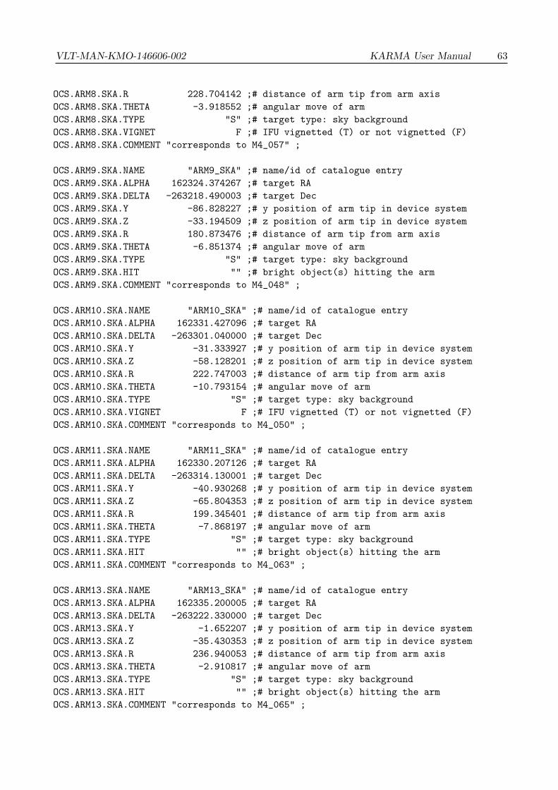
VLT-MAN-KMO-146606-002 KARMA User Manual 63
OCS.ARM8.SKA.R 228.704142 ;# distance of arm tip from arm axis
OCS.ARM8.SKA.THETA -3.918552 ;# angular move of arm
OCS.ARM8.SKA.TYPE "S" ;# target type: sky background
OCS.ARM8.SKA.VIGNET F ;# IFU vignetted (T) or not vignetted (F)
OCS.ARM8.SKA.COMMENT "corresponds to M4_057" ;
OCS.ARM9.SKA.NAME "ARM9_SKA" ;# name/id of catalogue entry
OCS.ARM9.SKA.ALPHA 162324.374267 ;# target RA
OCS.ARM9.SKA.DELTA -263218.490003 ;# target Dec
OCS.ARM9.SKA.Y -86.828227 ;# y position of arm tip in device system
OCS.ARM9.SKA.Z -33.194509 ;# z position of arm tip in device system
OCS.ARM9.SKA.R 180.873476 ;# distance of arm tip from arm axis
OCS.ARM9.SKA.THETA -6.851374 ;# angular move of arm
OCS.ARM9.SKA.TYPE "S" ;# target type: sky background
OCS.ARM9.SKA.HIT "" ;# bright object(s) hitting the arm
OCS.ARM9.SKA.COMMENT "corresponds to M4_048" ;
OCS.ARM10.SKA.NAME "ARM10_SKA" ;# name/id of catalogue entry
OCS.ARM10.SKA.ALPHA 162331.427096 ;# target RA
OCS.ARM10.SKA.DELTA -263301.040000 ;# target Dec
OCS.ARM10.SKA.Y -31.333927 ;# y position of arm tip in device system
OCS.ARM10.SKA.Z -58.128201 ;# z position of arm tip in device system
OCS.ARM10.SKA.R 222.747003 ;# distance of arm tip from arm axis
OCS.ARM10.SKA.THETA -10.793154 ;# angular move of arm
OCS.ARM10.SKA.TYPE "S" ;# target type: sky background
OCS.ARM10.SKA.VIGNET F ;# IFU vignetted (T) or not vignetted (F)
OCS.ARM10.SKA.COMMENT "corresponds to M4_050" ;
OCS.ARM11.SKA.NAME "ARM11_SKA" ;# name/id of catalogue entry
OCS.ARM11.SKA.ALPHA 162330.207126 ;# target RA
OCS.ARM11.SKA.DELTA -263314.130001 ;# target Dec
OCS.ARM11.SKA.Y -40.930268 ;# y position of arm tip in device system
OCS.ARM11.SKA.Z -65.804353 ;# z position of arm tip in device system
OCS.ARM11.SKA.R 199.345401 ;# distance of arm tip from arm axis
OCS.ARM11.SKA.THETA -7.868197 ;# angular move of arm
OCS.ARM11.SKA.TYPE "S" ;# target type: sky background
OCS.ARM11.SKA.HIT "" ;# bright object(s) hitting the arm
OCS.ARM11.SKA.COMMENT "corresponds to M4_063" ;
OCS.ARM13.SKA.NAME "ARM13_SKA" ;# name/id of catalogue entry
OCS.ARM13.SKA.ALPHA 162335.200005 ;# target RA
OCS.ARM13.SKA.DELTA -263222.330000 ;# target Dec
OCS.ARM13.SKA.Y -1.652207 ;# y position of arm tip in device system
OCS.ARM13.SKA.Z -35.430353 ;# z position of arm tip in device system
OCS.ARM13.SKA.R 236.940053 ;# distance of arm tip from arm axis
OCS.ARM13.SKA.THETA -2.910817 ;# angular move of arm
OCS.ARM13.SKA.TYPE "S" ;# target type: sky background
OCS.ARM13.SKA.HIT "" ;# bright object(s) hitting the arm
OCS.ARM13.SKA.COMMENT "corresponds to M4_065" ;
64 KARMA User Manual VLT-MAN-KMO-146606-002
OCS.ARM15.SKA.NAME "ARM15_SKA" ;# name/id of catalogue entry
OCS.ARM15.SKA.ALPHA 162339.397903 ;# target RA
OCS.ARM15.SKA.DELTA -263444.330001 ;# target Dec
OCS.ARM15.SKA.Y 31.365418 ;# y position of arm tip in device system
OCS.ARM15.SKA.Z -118.687542 ;# z position of arm tip in device system
OCS.ARM15.SKA.R 149.052993 ;# distance of arm tip from arm axis
OCS.ARM15.SKA.THETA -6.009651 ;# angular move of arm
OCS.ARM15.SKA.TYPE "S" ;# target type: sky background
OCS.ARM15.SKA.HIT "" ;# bright object(s) hitting the arm
OCS.ARM15.SKA.COMMENT "corresponds to M4_052" ;
OCS.ARM16.SKA.NAME "ARM16_SKA" ;# name/id of catalogue entry
OCS.ARM16.SKA.ALPHA 162335.355001 ;# target RA
OCS.ARM16.SKA.DELTA -263212.530000 ;# target Dec
OCS.ARM16.SKA.Y -0.432731 ;# y position of arm tip in device system
OCS.ARM16.SKA.Z -29.684569 ;# z position of arm tip in device system
OCS.ARM16.SKA.R 243.025314 ;# distance of arm tip from arm axis
OCS.ARM16.SKA.THETA 2.773529 ;# angular move of arm
OCS.ARM16.SKA.TYPE "S" ;# target type: sky background
OCS.ARM16.SKA.VIGNET F ;# IFU vignetted (T) or not vignetted (F)
OCS.ARM16.SKA.COMMENT "corresponds to M4_054" ;
OCS.ARM18.SKA.NAME "ARM18_SKA" ;# name/id of catalogue entry
OCS.ARM18.SKA.ALPHA 162336.143982 ;# target RA
OCS.ARM18.SKA.DELTA -263151.590000 ;# target Dec
OCS.ARM18.SKA.Y 5.775287 ;# y position of arm tip in device system
OCS.ARM18.SKA.Z -17.407433 ;# z position of arm tip in device system
OCS.ARM18.SKA.R 255.029041 ;# distance of arm tip from arm axis
OCS.ARM18.SKA.THETA 2.313423 ;# angular move of arm
OCS.ARM18.SKA.TYPE "S" ;# target type: sky background
OCS.ARM18.SKA.VIGNET F ;# IFU vignetted (T) or not vignetted (F)
OCS.ARM18.SKA.COMMENT "corresponds to M4_049" ;
OCS.ARM19.SKA.NAME "ARM19_SKA" ;# name/id of catalogue entry
OCS.ARM19.SKA.ALPHA 162346.322736 ;# target RA
OCS.ARM19.SKA.DELTA -263217.240003 ;# target Dec
OCS.ARM19.SKA.Y 85.860756 ;# y position of arm tip in device system
OCS.ARM19.SKA.Z -32.461284 ;# z position of arm tip in device system
OCS.ARM19.SKA.R 178.275667 ;# distance of arm tip from arm axis
OCS.ARM19.SKA.THETA -0.921517 ;# angular move of arm
OCS.ARM19.SKA.TYPE "S" ;# target type: sky background
OCS.ARM19.SKA.HIT "" ;# bright object(s) hitting the arm
OCS.ARM19.SKA.COMMENT "corresponds to M4_059" ;
OCS.ARM20.SKA.NAME "ARM20_SKA" ;# name/id of catalogue entry
OCS.ARM20.SKA.ALPHA 162340.100886 ;# target RA
OCS.ARM20.SKA.DELTA -263129.770001 ;# target Dec
OCS.ARM20.SKA.Y 36.911856 ;# y position of arm tip in device system
OCS.ARM20.SKA.Z -4.617024 ;# z position of arm tip in device system
OCS.ARM20.SKA.R 232.801412 ;# distance of arm tip from arm axis

VLT-MAN-KMO-146606-002 KARMA User Manual 65
OCS.ARM20.SKA.THETA -0.059176 ;# angular move of arm
OCS.ARM20.SKA.TYPE "S" ;# target type: sky background
OCS.ARM20.SKA.VIGNET F ;# IFU vignetted (T) or not vignetted (F)
OCS.ARM20.SKA.COMMENT "corresponds to M4_061" ;
OCS.ARM21.SKA.NAME "ARM21_SKA" ;# name/id of catalogue entry
OCS.ARM21.SKA.ALPHA 162347.403710 ;# target RA
OCS.ARM21.SKA.DELTA -263136.390004 ;# target Dec
OCS.ARM21.SKA.Y 94.375123 ;# y position of arm tip in device system
OCS.ARM21.SKA.Z -8.513928 ;# z position of arm tip in device system
OCS.ARM21.SKA.R 178.753107 ;# distance of arm tip from arm axis
OCS.ARM21.SKA.THETA 6.669102 ;# angular move of arm
OCS.ARM21.SKA.TYPE "S" ;# target type: sky background
OCS.ARM21.SKA.HIT "" ;# bright object(s) hitting the arm
OCS.ARM21.SKA.COMMENT "corresponds to M4_060" ;
OCS.ARM22.SKA.NAME "ARM22_SKA" ;# name/id of catalogue entry
OCS.ARM22.SKA.ALPHA 162340.855868 ;# target RA
OCS.ARM22.SKA.DELTA -263111.560001 ;# target Dec
OCS.ARM22.SKA.Y 42.854579 ;# y position of arm tip in device system
OCS.ARM22.SKA.Z 6.058593 ;# z position of arm tip in device system
OCS.ARM22.SKA.R 228.344666 ;# distance of arm tip from arm axis
OCS.ARM22.SKA.THETA 2.711510 ;# angular move of arm
OCS.ARM22.SKA.TYPE "S" ;# target type: sky background
OCS.ARM22.SKA.VIGNET F ;# IFU vignetted (T) or not vignetted (F)
OCS.ARM22.SKA.COMMENT "corresponds to M4_055" ;
OCS.ARM24.SKA.NAME "ARM24_SKA" ;# name/id of catalogue entry
OCS.ARM24.SKA.ALPHA 162344.053791 ;# target RA
OCS.ARM24.SKA.DELTA -262956.140002 ;# target Dec
OCS.ARM24.SKA.Y 68.032057 ;# y position of arm tip in device system
OCS.ARM24.SKA.Z 50.271884 ;# z position of arm tip in device system
OCS.ARM24.SKA.R 190.142965 ;# distance of arm tip from arm axis
OCS.ARM24.SKA.THETA 7.059896 ;# angular move of arm
OCS.ARM24.SKA.TYPE "S" ;# target type: sky background
OCS.ARM24.SKA.VIGNET F ;# IFU vignetted (T) or not vignetted (F)
OCS.ARM24.SKA.COMMENT "corresponds to M4_056" ;
#------------------------------------------------------------------------------
# Arm configuration at first ("Science") position
OCS.TARG.SCI.ALPHA 162335.410000 ;# telescope pointing RA
OCS.TARG.SCI.DELTA -263131.900000 ;# telescope pointing Dec
OCS.ROT.SCI.OFFANGLE 0.000000 ;# rotator angle
OCS.ARM1.SCI.NAME "M4_037" ;# name/id of catalogue entry
OCS.ARM1.SCI.ALPHA 162338.605000 ;# target RA
OCS.ARM1.SCI.DELTA -262915.950000 ;# target Dec
OCS.ARM1.SCI.Y 25.149100 ;# y position of arm tip in device system
OCS.ARM1.SCI.Z 79.706718 ;# z position of arm tip in device system
66 KARMA User Manual VLT-MAN-KMO-146606-002
OCS.ARM1.SCI.R 186.877826 ;# distance of arm tip from arm axis
OCS.ARM1.SCI.THETA -2.228802 ;# angular move of arm
OCS.ARM1.SCI.PRIOR 1 ;# target priority
OCS.ARM1.SCI.TYPE "O" ;# target type: science
OCS.ARM1.SCI.MAG 10.46 ;# magnitude as given in catalogue
OCS.ARM1.SCI.BAND "J" ;# wavelength band as given in catalogue
OCS.ARM1.SCI.HIT "" ;# bright object(s) hitting the arm
OCS.ARM1.SCI.COMMENT "" ;
OCS.ARM2.SCI.NAME "M4_009" ;# name/id of catalogue entry
OCS.ARM2.SCI.ALPHA 162336.453000 ;# target RA
OCS.ARM2.SCI.DELTA -263043.370000 ;# target Dec
OCS.ARM2.SCI.Y 8.208126 ;# y position of arm tip in device system
OCS.ARM2.SCI.Z 28.453191 ;# z position of arm tip in device system
OCS.ARM2.SCI.R 240.759504 ;# distance of arm tip from arm axis
OCS.ARM2.SCI.THETA 1.052884 ;# angular move of arm
OCS.ARM2.SCI.PRIOR 1 ;# target priority
OCS.ARM2.SCI.TYPE "O" ;# target type: science
OCS.ARM2.SCI.MAG 9.98 ;# magnitude as given in catalogue
OCS.ARM2.SCI.BAND "J" ;# wavelength band as given in catalogue
OCS.ARM2.SCI.VIGNET F ;# IFU vignetted (T) or not vignetted (F)
OCS.ARM2.SCI.COMMENT "" ;
OCS.ARM3.SCI.NAME "M4_034" ;# name/id of catalogue entry
OCS.ARM3.SCI.ALPHA 162330.676000 ;# target RA
OCS.ARM3.SCI.DELTA -262939.060000 ;# target Dec
OCS.ARM3.SCI.Y -37.261090 ;# y position of arm tip in device system
OCS.ARM3.SCI.Z 66.155675 ;# z position of arm tip in device system
OCS.ARM3.SCI.R 201.544551 ;# distance of arm tip from arm axis
OCS.ARM3.SCI.THETA -8.073983 ;# angular move of arm
OCS.ARM3.SCI.PRIOR 1 ;# target priority
OCS.ARM3.SCI.TYPE "O" ;# target type: science
OCS.ARM3.SCI.MAG 9.96 ;# magnitude as given in catalogue
OCS.ARM3.SCI.BAND "J" ;# wavelength band as given in catalogue
OCS.ARM3.SCI.HIT "" ;# bright object(s) hitting the arm
OCS.ARM3.SCI.COMMENT "" ;
OCS.ARM4.SCI.NAME "M4_025" ;# name/id of catalogue entry
OCS.ARM4.SCI.ALPHA 162331.449000 ;# target RA
OCS.ARM4.SCI.DELTA -263024.730000 ;# target Dec
OCS.ARM4.SCI.Y -31.173399 ;# y position of arm tip in device system
OCS.ARM4.SCI.Z 39.380032 ;# z position of arm tip in device system
OCS.ARM4.SCI.R 222.112844 ;# distance of arm tip from arm axis
OCS.ARM4.SCI.THETA -3.544121 ;# angular move of arm
OCS.ARM4.SCI.PRIOR 1 ;# target priority
OCS.ARM4.SCI.TYPE "O" ;# target type: science
OCS.ARM4.SCI.MAG 9.58 ;# magnitude as given in catalogue
OCS.ARM4.SCI.BAND "J" ;# wavelength band as given in catalogue
OCS.ARM4.SCI.VIGNET F ;# IFU vignetted (T) or not vignetted (F)
OCS.ARM4.SCI.COMMENT "" ;
VLT-MAN-KMO-146606-002 KARMA User Manual 67
OCS.ARM5.SCI.NAME "M4_017" ;# name/id of catalogue entry
OCS.ARM5.SCI.ALPHA 162327.006000 ;# target RA
OCS.ARM5.SCI.DELTA -263044.450000 ;# target Dec
OCS.ARM5.SCI.Y -66.137021 ;# y position of arm tip in device system
OCS.ARM5.SCI.Z 27.811100 ;# z position of arm tip in device system
OCS.ARM5.SCI.R 210.693347 ;# distance of arm tip from arm axis
OCS.ARM5.SCI.THETA -9.711066 ;# angular move of arm
OCS.ARM5.SCI.PRIOR 1 ;# target priority
OCS.ARM5.SCI.TYPE "O" ;# target type: science
OCS.ARM5.SCI.MAG 10.59 ;# magnitude as given in catalogue
OCS.ARM5.SCI.BAND "J" ;# wavelength band as given in catalogue
OCS.ARM5.SCI.HIT "" ;# bright object(s) hitting the arm
OCS.ARM5.SCI.COMMENT "" ;
OCS.ARM6.SCI.NAME "M4_022" ;# name/id of catalogue entry
OCS.ARM6.SCI.ALPHA 162333.974000 ;# target RA
OCS.ARM6.SCI.DELTA -263112.660000 ;# target Dec
OCS.ARM6.SCI.Y -11.300129 ;# y position of arm tip in device system
OCS.ARM6.SCI.Z 11.280224 ;# z position of arm tip in device system
OCS.ARM6.SCI.R 254.176470 ;# distance of arm tip from arm axis
OCS.ARM6.SCI.THETA 0.466646 ;# angular move of arm
OCS.ARM6.SCI.PRIOR 1 ;# target priority
OCS.ARM6.SCI.TYPE "O" ;# target type: science
OCS.ARM6.SCI.MAG 10.53 ;# magnitude as given in catalogue
OCS.ARM6.SCI.BAND "J" ;# wavelength band as given in catalogue
OCS.ARM6.SCI.VIGNET F ;# IFU vignetted (T) or not vignetted (F)
OCS.ARM6.SCI.COMMENT "" ;
OCS.ARM7.SCI.NAME "M4_019" ;# name/id of catalogue entry
OCS.ARM7.SCI.ALPHA 162322.783000 ;# target RA
OCS.ARM7.SCI.DELTA -263000.160000 ;# target Dec
OCS.ARM7.SCI.Y -99.381443 ;# y position of arm tip in device system
OCS.ARM7.SCI.Z 53.767164 ;# z position of arm tip in device system
OCS.ARM7.SCI.R 158.037166 ;# distance of arm tip from arm axis
OCS.ARM7.SCI.THETA 4.224863 ;# angular move of arm
OCS.ARM7.SCI.PRIOR 1 ;# target priority
OCS.ARM7.SCI.TYPE "O" ;# target type: science
OCS.ARM7.SCI.MAG 10.56 ;# magnitude as given in catalogue
OCS.ARM7.SCI.HIT "" ;# bright object(s) hitting the arm
OCS.ARM7.SCI.COMMENT "marker position" ;
OCS.ARM8.SCI.NAME "M4_033" ;# name/id of catalogue entry
OCS.ARM8.SCI.ALPHA 162333.023000 ;# target RA
OCS.ARM8.SCI.DELTA -263134.760000 ;# target Dec
OCS.ARM8.SCI.Y -18.782705 ;# y position of arm tip in device system
OCS.ARM8.SCI.Z -1.677557 ;# z position of arm tip in device system
OCS.ARM8.SCI.R 251.630596 ;# distance of arm tip from arm axis
OCS.ARM8.SCI.THETA -0.936983 ;# angular move of arm
OCS.ARM8.SCI.PRIOR 1 ;# target priority

68 KARMA User Manual VLT-MAN-KMO-146606-002
OCS.ARM8.SCI.TYPE "O" ;# target type: science
OCS.ARM8.SCI.MAG 10.58 ;# magnitude as given in catalogue
OCS.ARM8.SCI.VIGNET F ;# IFU vignetted (T) or not vignetted (F)
OCS.ARM8.SCI.COMMENT "marker position" ;
OCS.ARM9.SCI.NAME "M4_003" ;# name/id of catalogue entry
OCS.ARM9.SCI.ALPHA 162321.150000 ;# target RA
OCS.ARM9.SCI.DELTA -263159.890000 ;# target Dec
OCS.ARM9.SCI.Y -112.201541 ;# y position of arm tip in device system
OCS.ARM9.SCI.Z -16.436636 ;# z position of arm tip in device system
OCS.ARM9.SCI.R 156.621648 ;# distance of arm tip from arm axis
OCS.ARM9.SCI.THETA -0.603904 ;# angular move of arm
OCS.ARM9.SCI.PRIOR 1 ;# target priority
OCS.ARM9.SCI.TYPE "O" ;# target type: science
OCS.ARM9.SCI.MAG 10.45 ;# magnitude as given in catalogue
OCS.ARM9.SCI.BAND "J" ;# wavelength band as given in catalogue
OCS.ARM9.SCI.HIT "" ;# bright object(s) hitting the arm
OCS.ARM9.SCI.COMMENT "" ;
OCS.ARM10.SCI.NAME "M4_015" ;# name/id of catalogue entry
OCS.ARM10.SCI.ALPHA 162331.959000 ;# target RA
OCS.ARM10.SCI.DELTA -263145.740000 ;# target Dec
OCS.ARM10.SCI.Y -27.154333 ;# y position of arm tip in device system
OCS.ARM10.SCI.Z -8.115968 ;# z position of arm tip in device system
OCS.ARM10.SCI.R 241.824131 ;# distance of arm tip from arm axis
OCS.ARM10.SCI.THETA 0.685539 ;# angular move of arm
OCS.ARM10.SCI.PRIOR 1 ;# target priority
OCS.ARM10.SCI.TYPE "O" ;# target type: science
OCS.ARM10.SCI.MAG 10.35 ;# magnitude as given in catalogue
OCS.ARM10.SCI.BAND "J" ;# wavelength band as given in catalogue
OCS.ARM10.SCI.VIGNET F ;# IFU vignetted (T) or not vignetted (F)
OCS.ARM10.SCI.COMMENT "" ;
OCS.ARM11.SCI.NAME "M4_016" ;# name/id of catalogue entry
OCS.ARM11.SCI.ALPHA 162323.543000 ;# target RA
OCS.ARM11.SCI.DELTA -263341.280000 ;# target Dec
OCS.ARM11.SCI.Y -93.349859 ;# y position of arm tip in device system
OCS.ARM11.SCI.Z -75.874015 ;# z position of arm tip in device system
OCS.ARM11.SCI.R 149.789253 ;# distance of arm tip from arm axis
OCS.ARM11.SCI.THETA -1.288059 ;# angular move of arm
OCS.ARM11.SCI.PRIOR 1 ;# target priority
OCS.ARM11.SCI.TYPE "O" ;# target type: science
OCS.ARM11.SCI.MAG 10.29 ;# magnitude as given in catalogue
OCS.ARM11.SCI.BAND "J" ;# wavelength band as given in catalogue
OCS.ARM11.SCI.HIT "" ;# bright object(s) hitting the arm
OCS.ARM11.SCI.COMMENT "" ;
OCS.ARM12.SCI.NAME "M4_001" ;# name/id of catalogue entry
OCS.ARM12.SCI.ALPHA 162334.772000 ;# target RA
OCS.ARM12.SCI.DELTA -263135.000000 ;# target Dec

VLT-MAN-KMO-146606-002 KARMA User Manual 69
OCS.ARM12.SCI.Y -5.020259 ;# y position of arm tip in device system
OCS.ARM12.SCI.Z -1.817594 ;# z position of arm tip in device system
OCS.ARM12.SCI.R 265.517446 ;# distance of arm tip from arm axis
OCS.ARM12.SCI.THETA 0.620699 ;# angular move of arm
OCS.ARM12.SCI.PRIOR 1 ;# target priority
OCS.ARM12.SCI.TYPE "O" ;# target type: science
OCS.ARM12.SCI.MAG 10.21 ;# magnitude as given in catalogue
OCS.ARM12.SCI.BAND "J" ;# wavelength band as given in catalogue
OCS.ARM12.SCI.VIGNET F ;# IFU vignetted (T) or not vignetted (F)
OCS.ARM12.SCI.COMMENT "" ;
OCS.ARM13.SCI.NAME "M4_007" ;# name/id of catalogue entry
OCS.ARM13.SCI.ALPHA 162327.082000 ;# target RA
OCS.ARM13.SCI.DELTA -263329.700000 ;# target Dec
OCS.ARM13.SCI.Y -65.512718 ;# y position of arm tip in device system
OCS.ARM13.SCI.Z -69.075474 ;# z position of arm tip in device system
OCS.ARM13.SCI.R 184.292678 ;# distance of arm tip from arm axis
OCS.ARM13.SCI.THETA 10.660397 ;# angular move of arm
OCS.ARM13.SCI.PRIOR 1 ;# target priority
OCS.ARM13.SCI.TYPE "O" ;# target type: science
OCS.ARM13.SCI.MAG 10.54 ;# magnitude as given in catalogue
OCS.ARM13.SCI.BAND "J" ;# wavelength band as given in catalogue
OCS.ARM13.SCI.HIT "" ;# bright object(s) hitting the arm
OCS.ARM13.SCI.COMMENT "" ;
OCS.ARM14.SCI.NAME "M4_013" ;# name/id of catalogue entry
OCS.ARM14.SCI.ALPHA 162334.940000 ;# target RA
OCS.ARM14.SCI.DELTA -263158.480000 ;# target Dec
OCS.ARM14.SCI.Y -3.698100 ;# y position of arm tip in device system
OCS.ARM14.SCI.Z -15.583987 ;# z position of arm tip in device system
OCS.ARM14.SCI.R 254.071881 ;# distance of arm tip from arm axis
OCS.ARM14.SCI.THETA 0.368113 ;# angular move of arm
OCS.ARM14.SCI.PRIOR 1 ;# target priority
OCS.ARM14.SCI.TYPE "O" ;# target type: science
OCS.ARM14.SCI.MAG 10.54 ;# magnitude as given in catalogue
OCS.ARM14.SCI.BAND "J" ;# wavelength band as given in catalogue
OCS.ARM14.SCI.VIGNET F ;# IFU vignetted (T) or not vignetted (F)
OCS.ARM14.SCI.COMMENT "" ;
OCS.ARM15.SCI.NAME "M4_004" ;# name/id of catalogue entry
OCS.ARM15.SCI.ALPHA 162333.861000 ;# target RA
OCS.ARM15.SCI.DELTA -263419.810000 ;# target Dec
OCS.ARM15.SCI.Y -12.183825 ;# y position of arm tip in device system
OCS.ARM15.SCI.Z -98.446602 ;# z position of arm tip in device system
OCS.ARM15.SCI.R 175.762857 ;# distance of arm tip from arm axis
OCS.ARM15.SCI.THETA 8.154085 ;# angular move of arm
OCS.ARM15.SCI.PRIOR 1 ;# target priority
OCS.ARM15.SCI.TYPE "O" ;# target type: science
OCS.ARM15.SCI.MAG 9.72 ;# magnitude as given in catalogue
OCS.ARM15.SCI.BAND "J" ;# wavelength band as given in catalogue

70 KARMA User Manual VLT-MAN-KMO-146606-002
OCS.ARM15.SCI.HIT "" ;# bright object(s) hitting the arm
OCS.ARM15.SCI.COMMENT "" ;
OCS.ARM16.SCI.NAME "ARM16_SCI" ;# name/id of catalogue entry
OCS.ARM16.SCI.ALPHA 162338.226244 ;# target RA
OCS.ARM16.SCI.DELTA -263404.210032 ;# target Dec
OCS.ARM16.SCI.Y 22.152307 ;# y position of arm tip in device system
OCS.ARM16.SCI.Z -89.300987 ;# z position of arm tip in device system
OCS.ARM16.SCI.R 179.543384 ;# distance of arm tip from arm axis
OCS.ARM16.SCI.THETA 4.378733 ;# angular move of arm
OCS.ARM16.SCI.TYPE "S" ;# target type: sky background
OCS.ARM16.SCI.VIGNET F ;# IFU vignetted (T) or not vignetted (F)
OCS.ARM16.SCI.COMMENT "corresponds to M4_027" ;
OCS.ARM17.SCI.NAME "M4_023" ;# name/id of catalogue entry
OCS.ARM17.SCI.ALPHA 162336.587000 ;# target RA
OCS.ARM17.SCI.DELTA -263229.450000 ;# target Dec
OCS.ARM17.SCI.Y 9.260292 ;# y position of arm tip in device system
OCS.ARM17.SCI.Z -33.741969 ;# z position of arm tip in device system
OCS.ARM17.SCI.R 237.959456 ;# distance of arm tip from arm axis
OCS.ARM17.SCI.THETA 3.178506 ;# angular move of arm
OCS.ARM17.SCI.PRIOR 1 ;# target priority
OCS.ARM17.SCI.TYPE "O" ;# target type: science
OCS.ARM17.SCI.MAG 10.54 ;# magnitude as given in catalogue
OCS.ARM17.SCI.BAND "J" ;# wavelength band as given in catalogue
OCS.ARM17.SCI.HIT "M4_090" ;# bright object(s) hitting the arm
OCS.ARM17.SCI.COMMENT "" ;
OCS.ARM18.SCI.NAME "M4_018" ;# name/id of catalogue entry
OCS.ARM18.SCI.ALPHA 162335.639000 ;# target RA
OCS.ARM18.SCI.DELTA -263154.480000 ;# target Dec
OCS.ARM18.SCI.Y 1.801858 ;# y position of arm tip in device system
OCS.ARM18.SCI.Z -13.238750 ;# z position of arm tip in device system
OCS.ARM18.SCI.R 260.681005 ;# distance of arm tip from arm axis
OCS.ARM18.SCI.THETA 2.067842 ;# angular move of arm
OCS.ARM18.SCI.PRIOR 1 ;# target priority
OCS.ARM18.SCI.TYPE "O" ;# target type: science
OCS.ARM18.SCI.MAG 9.87 ;# magnitude as given in catalogue
OCS.ARM18.SCI.BAND "J" ;# wavelength band as given in catalogue
OCS.ARM18.SCI.VIGNET F ;# IFU vignetted (T) or not vignetted (F)
OCS.ARM18.SCI.COMMENT "" ;
OCS.ARM19.SCI.NAME "M4_043" ;# name/id of catalogue entry
OCS.ARM19.SCI.ALPHA 162350.358000 ;# target RA
OCS.ARM19.SCI.DELTA -263247.830000 ;# target Dec
OCS.ARM19.SCI.Y 117.601265 ;# y position of arm tip in device system
OCS.ARM19.SCI.Z -44.546625 ;# z position of arm tip in device system
OCS.ARM19.SCI.R 144.354648 ;# distance of arm tip from arm axis
OCS.ARM19.SCI.THETA -1.527625 ;# angular move of arm
OCS.ARM19.SCI.PRIOR 1 ;# target priority
VLT-MAN-KMO-146606-002 KARMA User Manual 71
OCS.ARM19.SCI.TYPE "O" ;# target type: science
OCS.ARM19.SCI.MAG 9.92 ;# magnitude as given in catalogue
OCS.ARM19.SCI.BAND "J" ;# wavelength band as given in catalogue
OCS.ARM19.SCI.HIT "" ;# bright object(s) hitting the arm
OCS.ARM19.SCI.COMMENT "" ;
OCS.ARM20.SCI.NAME "M4_020" ;# name/id of catalogue entry
OCS.ARM20.SCI.ALPHA 162338.925000 ;# target RA
OCS.ARM20.SCI.DELTA -263203.500000 ;# target Dec
OCS.ARM20.SCI.Y 27.656731 ;# y position of arm tip in device system
OCS.ARM20.SCI.Z -18.528784 ;# z position of arm tip in device system
OCS.ARM20.SCI.R 240.614543 ;# distance of arm tip from arm axis
OCS.ARM20.SCI.THETA 3.516980 ;# angular move of arm
OCS.ARM20.SCI.PRIOR 1 ;# target priority
OCS.ARM20.SCI.TYPE "O" ;# target type: science
OCS.ARM20.SCI.MAG 10.46 ;# magnitude as given in catalogue
OCS.ARM20.SCI.BAND "J" ;# wavelength band as given in catalogue
OCS.ARM20.SCI.VIGNET F ;# IFU vignetted (T) or not vignetted (F)
OCS.ARM20.SCI.COMMENT "" ;
OCS.ARM21.SCI.NAME "M4_036" ;# name/id of catalogue entry
OCS.ARM21.SCI.ALPHA 162343.213000 ;# target RA
OCS.ARM21.SCI.DELTA -263153.910000 ;# target Dec
OCS.ARM21.SCI.Y 61.397007 ;# y position of arm tip in device system
OCS.ARM21.SCI.Z -12.912331 ;# z position of arm tip in device system
OCS.ARM21.SCI.R 211.838836 ;# distance of arm tip from arm axis
OCS.ARM21.SCI.THETA 5.639118 ;# angular move of arm
OCS.ARM21.SCI.PRIOR 1 ;# target priority
OCS.ARM21.SCI.TYPE "O" ;# target type: science
OCS.ARM21.SCI.MAG 9.96 ;# magnitude as given in catalogue
OCS.ARM21.SCI.BAND "J" ;# wavelength band as given in catalogue
OCS.ARM21.SCI.HIT "" ;# bright object(s) hitting the arm
OCS.ARM21.SCI.COMMENT "" ;
OCS.ARM22.SCI.NAME "M4_024" ;# name/id of catalogue entry
OCS.ARM22.SCI.ALPHA 162339.488000 ;# target RA
OCS.ARM22.SCI.DELTA -263111.440000 ;# target Dec
OCS.ARM22.SCI.Y 32.090571 ;# y position of arm tip in device system
OCS.ARM22.SCI.Z 11.993654 ;# z position of arm tip in device system
OCS.ARM22.SCI.R 235.765459 ;# distance of arm tip from arm axis
OCS.ARM22.SCI.THETA 0.291586 ;# angular move of arm
OCS.ARM22.SCI.PRIOR 1 ;# target priority
OCS.ARM22.SCI.TYPE "O" ;# target type: science
OCS.ARM22.SCI.MAG 9.86 ;# magnitude as given in catalogue
OCS.ARM22.SCI.BAND "J" ;# wavelength band as given in catalogue
OCS.ARM22.SCI.VIGNET F ;# IFU vignetted (T) or not vignetted (F)
OCS.ARM22.SCI.COMMENT "" ;
OCS.ARM23.SCI.NAME "M4_040" ;# name/id of catalogue entry
OCS.ARM23.SCI.ALPHA 162342.797000 ;# target RA
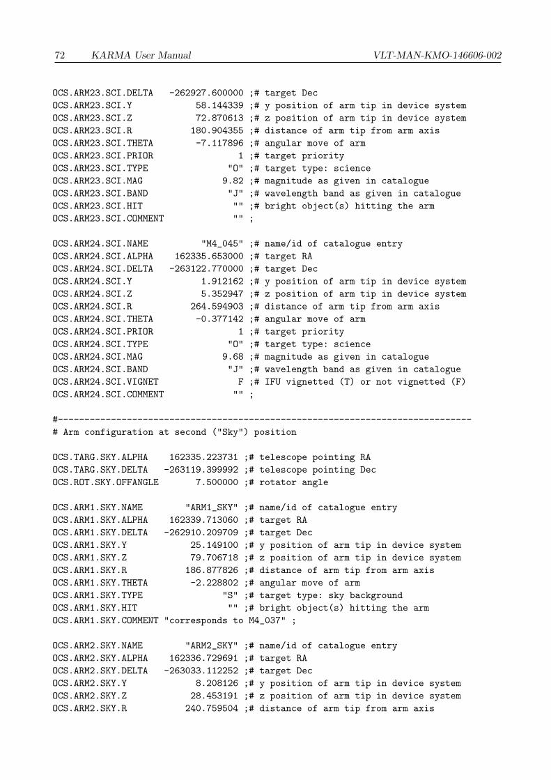
72 KARMA User Manual VLT-MAN-KMO-146606-002
OCS.ARM23.SCI.DELTA -262927.600000 ;# target Dec
OCS.ARM23.SCI.Y 58.144339 ;# y position of arm tip in device system
OCS.ARM23.SCI.Z 72.870613 ;# z position of arm tip in device system
OCS.ARM23.SCI.R 180.904355 ;# distance of arm tip from arm axis
OCS.ARM23.SCI.THETA -7.117896 ;# angular move of arm
OCS.ARM23.SCI.PRIOR 1 ;# target priority
OCS.ARM23.SCI.TYPE "O" ;# target type: science
OCS.ARM23.SCI.MAG 9.82 ;# magnitude as given in catalogue
OCS.ARM23.SCI.BAND "J" ;# wavelength band as given in catalogue
OCS.ARM23.SCI.HIT "" ;# bright object(s) hitting the arm
OCS.ARM23.SCI.COMMENT "" ;
OCS.ARM24.SCI.NAME "M4_045" ;# name/id of catalogue entry
OCS.ARM24.SCI.ALPHA 162335.653000 ;# target RA
OCS.ARM24.SCI.DELTA -263122.770000 ;# target Dec
OCS.ARM24.SCI.Y 1.912162 ;# y position of arm tip in device system
OCS.ARM24.SCI.Z 5.352947 ;# z position of arm tip in device system
OCS.ARM24.SCI.R 264.594903 ;# distance of arm tip from arm axis
OCS.ARM24.SCI.THETA -0.377142 ;# angular move of arm
OCS.ARM24.SCI.PRIOR 1 ;# target priority
OCS.ARM24.SCI.TYPE "O" ;# target type: science
OCS.ARM24.SCI.MAG 9.68 ;# magnitude as given in catalogue
OCS.ARM24.SCI.BAND "J" ;# wavelength band as given in catalogue
OCS.ARM24.SCI.VIGNET F ;# IFU vignetted (T) or not vignetted (F)
OCS.ARM24.SCI.COMMENT "" ;
#------------------------------------------------------------------------------
# Arm configuration at second ("Sky") position
OCS.TARG.SKY.ALPHA 162335.223731 ;# telescope pointing RA
OCS.TARG.SKY.DELTA -263119.399992 ;# telescope pointing Dec
OCS.ROT.SKY.OFFANGLE 7.500000 ;# rotator angle
OCS.ARM1.SKY.NAME "ARM1_SKY" ;# name/id of catalogue entry
OCS.ARM1.SKY.ALPHA 162339.713060 ;# target RA
OCS.ARM1.SKY.DELTA -262910.209709 ;# target Dec
OCS.ARM1.SKY.Y 25.149100 ;# y position of arm tip in device system
OCS.ARM1.SKY.Z 79.706718 ;# z position of arm tip in device system
OCS.ARM1.SKY.R 186.877826 ;# distance of arm tip from arm axis
OCS.ARM1.SKY.THETA -2.228802 ;# angular move of arm
OCS.ARM1.SKY.TYPE "S" ;# target type: sky background
OCS.ARM1.SKY.HIT "" ;# bright object(s) hitting the arm
OCS.ARM1.SKY.COMMENT "corresponds to M4_037" ;
OCS.ARM2.SKY.NAME "ARM2_SKY" ;# name/id of catalogue entry
OCS.ARM2.SKY.ALPHA 162336.729691 ;# target RA
OCS.ARM2.SKY.DELTA -263033.112252 ;# target Dec
OCS.ARM2.SKY.Y 8.208126 ;# y position of arm tip in device system
OCS.ARM2.SKY.Z 28.453191 ;# z position of arm tip in device system
OCS.ARM2.SKY.R 240.759504 ;# distance of arm tip from arm axis

VLT-MAN-KMO-146606-002 KARMA User Manual 73
OCS.ARM2.SKY.THETA 1.052884 ;# angular move of arm
OCS.ARM2.SKY.TYPE "S" ;# target type: sky background
OCS.ARM2.SKY.VIGNET F ;# IFU vignetted (T) or not vignetted (F)
OCS.ARM2.SKY.COMMENT "corresponds to M4_009" ;
OCS.ARM3.SKY.NAME "ARM3_SKY" ;# name/id of catalogue entry
OCS.ARM3.SKY.ALPHA 162331.627481 ;# target RA
OCS.ARM3.SKY.DELTA -262919.232109 ;# target Dec
OCS.ARM3.SKY.Y -37.261090 ;# y position of arm tip in device system
OCS.ARM3.SKY.Z 66.155675 ;# z position of arm tip in device system
OCS.ARM3.SKY.R 201.544551 ;# distance of arm tip from arm axis
OCS.ARM3.SKY.THETA -8.073983 ;# angular move of arm
OCS.ARM3.SKY.TYPE "S" ;# target type: sky background
OCS.ARM3.SKY.HIT "" ;# bright object(s) hitting the arm
OCS.ARM3.SKY.COMMENT "corresponds to M4_034" ;
OCS.ARM4.SKY.NAME "ARM4_SKY" ;# name/id of catalogue entry
OCS.ARM4.SKY.ALPHA 162331.949889 ;# target RA
OCS.ARM4.SKY.DELTA -263005.865702 ;# target Dec
OCS.ARM4.SKY.Y -31.173399 ;# y position of arm tip in device system
OCS.ARM4.SKY.Z 39.380032 ;# z position of arm tip in device system
OCS.ARM4.SKY.R 222.112844 ;# distance of arm tip from arm axis
OCS.ARM4.SKY.THETA -3.544121 ;# angular move of arm
OCS.ARM4.SKY.TYPE "S" ;# target type: sky background
OCS.ARM4.SKY.VIGNET F ;# IFU vignetted (T) or not vignetted (F)
OCS.ARM4.SKY.COMMENT "corresponds to M4_025" ;
OCS.ARM5.SKY.NAME "ARM5_SKY" ;# name/id of catalogue entry
OCS.ARM5.SKY.ALPHA 162327.353411 ;# target RA
OCS.ARM5.SKY.DELTA -263017.633911 ;# target Dec
OCS.ARM5.SKY.Y -66.137021 ;# y position of arm tip in device system
OCS.ARM5.SKY.Z 27.811100 ;# z position of arm tip in device system
OCS.ARM5.SKY.R 210.693347 ;# distance of arm tip from arm axis
OCS.ARM5.SKY.THETA -9.711066 ;# angular move of arm
OCS.ARM5.SKY.TYPE "S" ;# target type: sky background
OCS.ARM5.SKY.HIT "" ;# bright object(s) hitting the arm
OCS.ARM5.SKY.COMMENT "corresponds to M4_017" ;
OCS.ARM6.SKY.NAME "ARM6_SKY" ;# name/id of catalogue entry
OCS.ARM6.SKY.ALPHA 162333.987166 ;# target RA
OCS.ARM6.SKY.DELTA -263057.809009 ;# target Dec
OCS.ARM6.SKY.Y -11.300129 ;# y position of arm tip in device system
OCS.ARM6.SKY.Z 11.280224 ;# z position of arm tip in device system
OCS.ARM6.SKY.R 254.176470 ;# distance of arm tip from arm axis
OCS.ARM6.SKY.THETA 0.466646 ;# angular move of arm
OCS.ARM6.SKY.TYPE "S" ;# target type: sky background
OCS.ARM6.SKY.VIGNET F ;# IFU vignetted (T) or not vignetted (F)
OCS.ARM6.SKY.COMMENT "corresponds to M4_022" ;
OCS.ARM7.SKY.NAME "ARM7_SKY" ;# name/id of catalogue entry

74 KARMA User Manual VLT-MAN-KMO-146606-002
OCS.ARM7.SKY.ALPHA 162323.597389 ;# target RA
OCS.ARM7.SKY.DELTA -262926.324996 ;# target Dec
OCS.ARM7.SKY.Y -99.381443 ;# y position of arm tip in device system
OCS.ARM7.SKY.Z 53.767164 ;# z position of arm tip in device system
OCS.ARM7.SKY.R 158.037166 ;# distance of arm tip from arm axis
OCS.ARM7.SKY.THETA 4.224863 ;# angular move of arm
OCS.ARM7.SKY.TYPE "S" ;# target type: sky background
OCS.ARM7.SKY.HIT "" ;# bright object(s) hitting the arm
OCS.ARM7.SKY.COMMENT "corresponds to M4_019" ;
OCS.ARM8.SKY.NAME "ARM8_SKY" ;# name/id of catalogue entry
OCS.ARM8.SKY.ALPHA 162332.829422 ;# target RA
OCS.ARM8.SKY.DELTA -263118.053998 ;# target Dec
OCS.ARM8.SKY.Y -18.782705 ;# y position of arm tip in device system
OCS.ARM8.SKY.Z -1.677557 ;# z position of arm tip in device system
OCS.ARM8.SKY.R 251.630596 ;# distance of arm tip from arm axis
OCS.ARM8.SKY.THETA -0.936983 ;# angular move of arm
OCS.ARM8.SKY.TYPE "S" ;# target type: sky background
OCS.ARM8.SKY.VIGNET F ;# IFU vignetted (T) or not vignetted (F)
OCS.ARM8.SKY.COMMENT "corresponds to M4_033" ;
OCS.ARM9.SKY.NAME "ARM9_SKY" ;# name/id of catalogue entry
OCS.ARM9.SKY.ALPHA 162320.814376 ;# target RA
OCS.ARM9.SKY.DELTA -263122.170313 ;# target Dec
OCS.ARM9.SKY.Y -112.201541 ;# y position of arm tip in device system
OCS.ARM9.SKY.Z -16.436636 ;# z position of arm tip in device system
OCS.ARM9.SKY.R 156.621648 ;# distance of arm tip from arm axis
OCS.ARM9.SKY.THETA -0.603904 ;# angular move of arm
OCS.ARM9.SKY.TYPE "S" ;# target type: sky background
OCS.ARM9.SKY.HIT "" ;# bright object(s) hitting the arm
OCS.ARM9.SKY.COMMENT "corresponds to M4_003" ;
OCS.ARM10.SKY.NAME "ARM10_SKY" ;# name/id of catalogue entry
OCS.ARM10.SKY.ALPHA 162331.667785 ;# target RA
OCS.ARM10.SKY.DELTA -263127.076161 ;# target Dec
OCS.ARM10.SKY.Y -27.154333 ;# y position of arm tip in device system
OCS.ARM10.SKY.Z -8.115968 ;# z position of arm tip in device system
OCS.ARM10.SKY.R 241.824131 ;# distance of arm tip from arm axis
OCS.ARM10.SKY.THETA 0.685539 ;# angular move of arm
OCS.ARM10.SKY.TYPE "S" ;# target type: sky background
OCS.ARM10.SKY.VIGNET F ;# IFU vignetted (T) or not vignetted (F)
OCS.ARM10.SKY.COMMENT "corresponds to M4_015" ;
OCS.ARM11.SKY.NAME "ARM11_SKY" ;# name/id of catalogue entry
OCS.ARM11.SKY.ALPHA 162322.200362 ;# target RA
OCS.ARM11.SKY.DELTA -263306.884540 ;# target Dec
OCS.ARM11.SKY.Y -93.349859 ;# y position of arm tip in device system
OCS.ARM11.SKY.Z -75.874015 ;# z position of arm tip in device system
OCS.ARM11.SKY.R 149.789253 ;# distance of arm tip from arm axis
OCS.ARM11.SKY.THETA -1.288059 ;# angular move of arm

VLT-MAN-KMO-146606-002 KARMA User Manual 75
OCS.ARM11.SKY.TYPE "S" ;# target type: sky background
OCS.ARM11.SKY.HIT "" ;# bright object(s) hitting the arm
OCS.ARM11.SKY.COMMENT "corresponds to M4_016" ;
OCS.ARM12.SKY.NAME "ARM12_SKY" ;# name/id of catalogue entry
OCS.ARM12.SKY.ALPHA 162334.561061 ;# target RA
OCS.ARM12.SKY.DELTA -263121.355826 ;# target Dec
OCS.ARM12.SKY.Y -5.020259 ;# y position of arm tip in device system
OCS.ARM12.SKY.Z -1.817594 ;# z position of arm tip in device system
OCS.ARM12.SKY.R 265.517446 ;# distance of arm tip from arm axis
OCS.ARM12.SKY.THETA 0.620699 ;# angular move of arm
OCS.ARM12.SKY.TYPE "S" ;# target type: sky background
OCS.ARM12.SKY.VIGNET F ;# IFU vignetted (T) or not vignetted (F)
OCS.ARM12.SKY.COMMENT "corresponds to M4_001" ;
OCS.ARM13.SKY.NAME "ARM13_SKY" ;# name/id of catalogue entry
OCS.ARM13.SKY.ALPHA 162325.821480 ;# target RA
OCS.ARM13.SKY.DELTA -263301.603117 ;# target Dec
OCS.ARM13.SKY.Y -65.512718 ;# y position of arm tip in device system
OCS.ARM13.SKY.Z -69.075474 ;# z position of arm tip in device system
OCS.ARM13.SKY.R 184.292678 ;# distance of arm tip from arm axis
OCS.ARM13.SKY.THETA 10.660397 ;# angular move of arm
OCS.ARM13.SKY.TYPE "S" ;# target type: sky background
OCS.ARM13.SKY.HIT "" ;# bright object(s) hitting the arm
OCS.ARM13.SKY.COMMENT "corresponds to M4_007" ;
OCS.ARM14.SKY.NAME "ARM14_SKY" ;# name/id of catalogue entry
OCS.ARM14.SKY.ALPHA 162334.499255 ;# target RA
OCS.ARM14.SKY.DELTA -263144.929239 ;# target Dec
OCS.ARM14.SKY.Y -3.698100 ;# y position of arm tip in device system
OCS.ARM14.SKY.Z -15.583987 ;# z position of arm tip in device system
OCS.ARM14.SKY.R 254.071881 ;# distance of arm tip from arm axis
OCS.ARM14.SKY.THETA 0.368113 ;# angular move of arm
OCS.ARM14.SKY.TYPE "S" ;# target type: sky background
OCS.ARM14.SKY.VIGNET F ;# IFU vignetted (T) or not vignetted (F)
OCS.ARM14.SKY.COMMENT "corresponds to M4_013" ;
OCS.ARM15.SKY.NAME "ARM15_SKY" ;# name/id of catalogue entry
OCS.ARM15.SKY.ALPHA 162332.054434 ;# target RA
OCS.ARM15.SKY.DELTA -263403.159397 ;# target Dec
OCS.ARM15.SKY.Y -12.183825 ;# y position of arm tip in device system
OCS.ARM15.SKY.Z -98.446602 ;# z position of arm tip in device system
OCS.ARM15.SKY.R 175.762857 ;# distance of arm tip from arm axis
OCS.ARM15.SKY.THETA 8.154085 ;# angular move of arm
OCS.ARM15.SKY.TYPE "S" ;# target type: sky background
OCS.ARM15.SKY.HIT "" ;# bright object(s) hitting the arm
OCS.ARM15.SKY.COMMENT "corresponds to M4_004" ;
OCS.ARM16.SKY.NAME "M4_027" ;# name/id of catalogue entry
OCS.ARM16.SKY.ALPHA 162336.534000 ;# target RA

76 KARMA User Manual VLT-MAN-KMO-146606-002
OCS.ARM16.SKY.DELTA -263355.340000 ;# target Dec
OCS.ARM16.SKY.Y 22.152307 ;# y position of arm tip in device system
OCS.ARM16.SKY.Z -89.300987 ;# z position of arm tip in device system
OCS.ARM16.SKY.R 179.543384 ;# distance of arm tip from arm axis
OCS.ARM16.SKY.THETA 4.378733 ;# angular move of arm
OCS.ARM16.SKY.PRIOR 1 ;# target priority
OCS.ARM16.SKY.TYPE "O" ;# target type: science
OCS.ARM16.SKY.MAG 10.20 ;# magnitude as given in catalogue
OCS.ARM16.SKY.BAND "J" ;# wavelength band as given in catalogue
OCS.ARM16.SKY.VIGNET F ;# IFU vignetted (T) or not vignetted (F)
OCS.ARM16.SKY.COMMENT "" ;
OCS.ARM17.SKY.NAME "ARM17_SKY" ;# name/id of catalogue entry
OCS.ARM17.SKY.ALPHA 162335.830862 ;# target RA
OCS.ARM17.SKY.DELTA -263218.519440 ;# target Dec
OCS.ARM17.SKY.Y 9.260292 ;# y position of arm tip in device system
OCS.ARM17.SKY.Z -33.741969 ;# z position of arm tip in device system
OCS.ARM17.SKY.R 237.959456 ;# distance of arm tip from arm axis
OCS.ARM17.SKY.THETA 3.178506 ;# angular move of arm
OCS.ARM17.SKY.TYPE "S" ;# target type: sky background
OCS.ARM17.SKY.HIT "M4_088" ;# bright object(s) hitting the arm
OCS.ARM17.SKY.COMMENT "corresponds to M4_023" ;
OCS.ARM18.SKY.NAME "ARM18_SKY" ;# name/id of catalogue entry
OCS.ARM18.SKY.ALPHA 162335.231158 ;# target RA
OCS.ARM18.SKY.DELTA -263142.187968 ;# target Dec
OCS.ARM18.SKY.Y 1.801858 ;# y position of arm tip in device system
OCS.ARM18.SKY.Z -13.238750 ;# z position of arm tip in device system
OCS.ARM18.SKY.R 260.681005 ;# distance of arm tip from arm axis
OCS.ARM18.SKY.THETA 2.067842 ;# angular move of arm
OCS.ARM18.SKY.TYPE "S" ;# target type: sky background
OCS.ARM18.SKY.VIGNET F ;# IFU vignetted (T) or not vignetted (F)
OCS.ARM18.SKY.COMMENT "corresponds to M4_018" ;
OCS.ARM19.SKY.NAME "ARM19_SKY" ;# name/id of catalogue entry
OCS.ARM19.SKY.ALPHA 162349.305226 ;# target RA
OCS.ARM19.SKY.DELTA -263300.866502 ;# target Dec
OCS.ARM19.SKY.Y 117.601265 ;# y position of arm tip in device system
OCS.ARM19.SKY.Z -44.546625 ;# z position of arm tip in device system
OCS.ARM19.SKY.R 144.354648 ;# distance of arm tip from arm axis
OCS.ARM19.SKY.THETA -1.527625 ;# angular move of arm
OCS.ARM19.SKY.TYPE "S" ;# target type: sky background
OCS.ARM19.SKY.HIT "" ;# bright object(s) hitting the arm
OCS.ARM19.SKY.COMMENT "corresponds to M4_043" ;
OCS.ARM20.SKY.NAME "ARM20_SKY" ;# name/id of catalogue entry
OCS.ARM20.SKY.ALPHA 162338.401233 ;# target RA
OCS.ARM20.SKY.DELTA -263156.887212 ;# target Dec
OCS.ARM20.SKY.Y 27.656731 ;# y position of arm tip in device system
OCS.ARM20.SKY.Z -18.528784 ;# z position of arm tip in device system

VLT-MAN-KMO-146606-002 KARMA User Manual 77
OCS.ARM20.SKY.R 240.614543 ;# distance of arm tip from arm axis
OCS.ARM20.SKY.THETA 3.516980 ;# angular move of arm
OCS.ARM20.SKY.TYPE "S" ;# target type: sky background
OCS.ARM20.SKY.VIGNET F ;# IFU vignetted (T) or not vignetted (F)
OCS.ARM20.SKY.COMMENT "corresponds to M4_020" ;
OCS.ARM21.SKY.NAME "ARM21_SKY" ;# name/id of catalogue entry
OCS.ARM21.SKY.ALPHA 162342.745794 ;# target RA
OCS.ARM21.SKY.DELTA -263154.891056 ;# target Dec
OCS.ARM21.SKY.Y 61.397007 ;# y position of arm tip in device system
OCS.ARM21.SKY.Z -12.912331 ;# z position of arm tip in device system
OCS.ARM21.SKY.R 211.838836 ;# distance of arm tip from arm axis
OCS.ARM21.SKY.THETA 5.639118 ;# angular move of arm
OCS.ARM21.SKY.TYPE "S" ;# target type: sky background
OCS.ARM21.SKY.HIT "" ;# bright object(s) hitting the arm
OCS.ARM21.SKY.COMMENT "corresponds to M4_036" ;
OCS.ARM22.SKY.NAME "ARM22_SKY" ;# name/id of catalogue entry
OCS.ARM22.SKY.ALPHA 162339.465728 ;# target RA
OCS.ARM22.SKY.DELTA -263106.258881 ;# target Dec
OCS.ARM22.SKY.Y 32.090571 ;# y position of arm tip in device system
OCS.ARM22.SKY.Z 11.993654 ;# z position of arm tip in device system
OCS.ARM22.SKY.R 235.765459 ;# distance of arm tip from arm axis
OCS.ARM22.SKY.THETA 0.291586 ;# angular move of arm
OCS.ARM22.SKY.TYPE "S" ;# target type: sky background
OCS.ARM22.SKY.VIGNET F ;# IFU vignetted (T) or not vignetted (F)
OCS.ARM22.SKY.COMMENT "corresponds to M4_024" ;
OCS.ARM23.SKY.NAME "ARM23_SKY" ;# name/id of catalogue entry
OCS.ARM23.SKY.ALPHA 162343.755965 ;# target RA
OCS.ARM23.SKY.DELTA -262929.103735 ;# target Dec
OCS.ARM23.SKY.Y 58.144339 ;# y position of arm tip in device system
OCS.ARM23.SKY.Z 72.870613 ;# z position of arm tip in device system
OCS.ARM23.SKY.R 180.904355 ;# distance of arm tip from arm axis
OCS.ARM23.SKY.THETA -7.117896 ;# angular move of arm
OCS.ARM23.SKY.TYPE "S" ;# target type: sky background
OCS.ARM23.SKY.HIT "" ;# bright object(s) hitting the arm
OCS.ARM23.SKY.COMMENT "corresponds to M4_040" ;
OCS.ARM24.SKY.NAME "ARM24_SKY" ;# name/id of catalogue entry
OCS.ARM24.SKY.ALPHA 162335.553434 ;# target RA
OCS.ARM24.SKY.DELTA -263110.773786 ;# target Dec
OCS.ARM24.SKY.Y 1.912162 ;# y position of arm tip in device system
OCS.ARM24.SKY.Z 5.352947 ;# z position of arm tip in device system
OCS.ARM24.SKY.R 264.594903 ;# distance of arm tip from arm axis
OCS.ARM24.SKY.THETA -0.377142 ;# angular move of arm
OCS.ARM24.SKY.TYPE "S" ;# target type: sky background
OCS.ARM24.SKY.VIGNET F ;# IFU vignetted (T) or not vignetted (F)
OCS.ARM24.SKY.COMMENT "corresponds to M4_045" ;
#------------------------------------------------------------------------------