k7 / kr mini-lube - western filters · the macnaught k7/kr mini-lube is a completely portable ......
TRANSCRIPT
1
INSTRUCTION MANUAL
INTRODUCTION
GENERAL INFORMATION
KM228
0001
1108
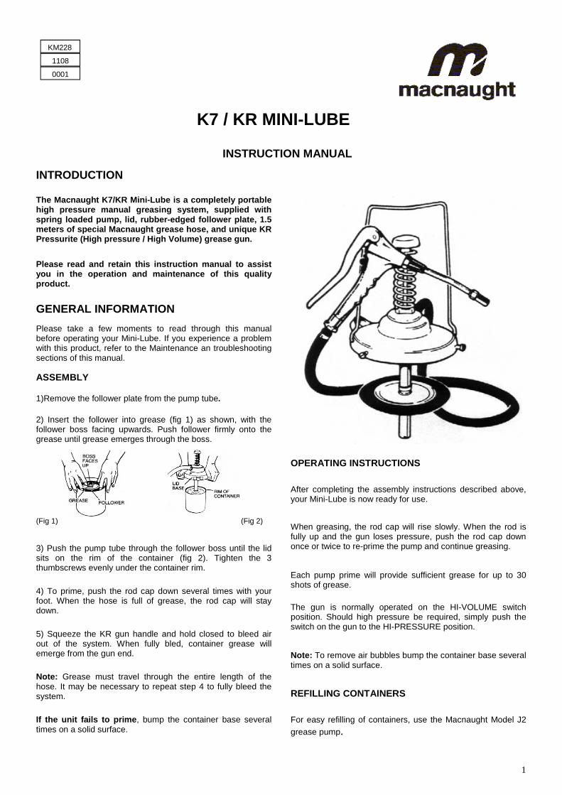
The Macnaught K7/KR Mini-Lube is a completely portable high pressure manual greasing system, supplied with spring loaded pump, lid, rubber-edged follower plate, 1.5 meters of special Macnaught grease hose, and unique KR Pressurite (High pressure / High Volume) grease gun.
K7 / KR MINI-LUBE
Please read and retain this instruction manual to assist you in the operation and maintenance of this quality product.
Please take a few moments to read through this manual before operating your Mini-Lube. If you experience a problem with this product, refer to the Maintenance an troubleshooting sections of this manual.
ASSEMBLY
1)Remove the follower plate from the pump tube.
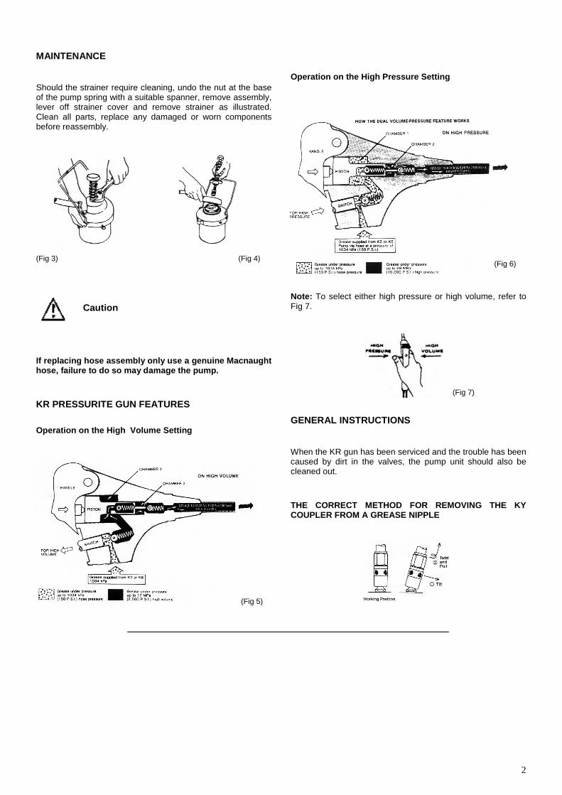
2) Insert the follower into grease (fig 1) as shown, with the follower boss facing upwards. Push follower firmly onto the grease until grease emerges through the boss.
3) Push the pump tube through the follower boss until the lid sits on the rim of the container (fig 2). Tighten the 3 thumbscrews evenly under the container rim.
4) To prime, push the rod cap down several times with your foot. When the hose is full of grease, the rod cap will stay down.
5) Squeeze the KR gun handle and hold closed to bleed air out of the system. When fully bled, container grease will emerge from the gun end.
Note: Grease must travel through the entire length of the hose. It may be necessary to repeat step 4 to fully bleed the system.
If the unit fails to prime, bump the container base several times on a solid surface.
OPERATING INSTRUCTIONS
After completing the assembly instructions described above, your Mini-Lube is now ready for use.
When greasing, the rod cap will rise slowly. When the rod is fully up and the gun loses pressure, push the rod cap down once or twice to re-prime the pump and continue greasing.
Each pump prime will provide sufficient grease for up to 30 shots of grease.
The gun is normally operated on the HI-VOLUME switch position. Should high pressure be required, simply push the switch on the gun to the HI-PRESSURE position.
Note: To remove air bubbles bump the container base several times on a solid surface.
(Fig 1) (Fig 2)
REFILLING CONTAINERS
For easy refilling of containers, use the Macnaught Model J2 grease pump.
2
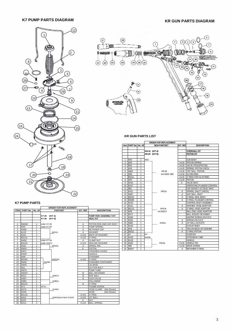
MAINTENANCE
Should the strainer require cleaning, undo the nut at the base of the pump spring with a suitable spanner, remove assembly, lever off strainer cover and remove strainer as illustrated. Clean all parts, replace any damaged or worn components before reassembly.
Caution
If replacing hose assembly only use a genuine Macnaught hose, failure to do so may damage the pump.
(Fig 3) (Fig 4)
KR PRESSURITE GUN FEATURES
Operation on the High Volume Setting
Operation on the High Pressure Setting
Note: To select either high pressure or high volume, refer to Fig 7.
(Fig 7)
(Fig 5)
(Fig 6)
GENERAL INSTRUCTIONS
When the KR gun has been serviced and the trouble has been caused by dirt in the valves, the pump unit should also be cleaned out.
THE CORRECT METHOD FOR REMOVING THE KY COUPLER FROM A GREASE NIPPLE
3
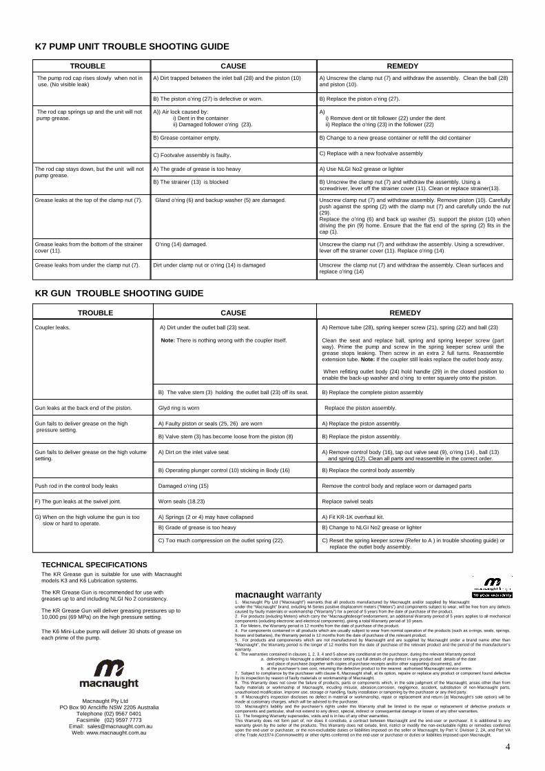
KR GUN PARTS DIAGRAM
KR GUN PARTS LIST
K7 PUMP PARTS DIAGRAM
ORDER FOR REPLACEMENTITEM PART No. No. off PART/SET KIT. REF DESCRIPTION
K7-2K (KIT A) PUMP ROD ASSEMBLY KITK7-3K (KIT B) SEAL KIT
1 KM194 1 order K7-2K A PISTON ROD AND CAP ASSY2 KM2 1 order K7-2K A PUMP SPRING3 KM56 1 A RETAINER CAP4 N125 1 N151s A WASHER5 N151 1 A & B BACK UP WASHER6 BS110 1 A & B O' RING7 KM50 1 order K7-2K A CLAMP NUT8 BS223 1 order N151s A & B SEALING WASHER9 N331 1 KM23s A SPIROL PIN10 KM24 1 A PISTON 11 KM17 1 STRAINER COVER12 KM29 1 HANDLE13 KM9 1 STRAINER14 BS240 1 KM226s A & B O' RING15 KM44 1 KM38s STRAINER CONTAINER16 KM45 1 LID BASE17 N52 3 GUTTER BOLT18 KM75 1 PUMP TUBE19 KM157 1 B BALL RETAINER20 N412 1 KM57s B 9/16" BALL21 KM57 1 B FOOTVALVE22 KM81 1 KM81s FOLLOWER23 BS214 1 B O' RING24 N72 3 N72s THUMB SCREW25 KH74 2 KH40s HOSE CLAMP (Not Shown)26 KH40 1 HOSE (Not Shown) 27 BS115 1 A & B O' RING28 N410 1 KM23s(incl item 9 &10) A & B 1/2" BALL29 N225 1 A NUT30 KH11 1 A & B BALL SPRING
K7 PUMP PARTS
1
2
3
4
5
6
7
8
9 10
11
12
13
14
15 16
17
18
19
20
21
22
23
24
27
28
29
30
ORDER FOR REPLACEMENTItem PART No. No. off NEW PART/SET KIT. REF DESCRIPTION
KR-1K (KIT A) OVERHAUL KITKR-2K (KIT B) PISTON KIT
1 KR2 1 KR2 GUN BODY2 KR3 1 A & B PISTON SPRING3 KR1 1 A & B VALVE STEM (PISTON)4 KH5 1 A & B SPRING, PISTON CHECK5 N403 1 KR-2K A & B 7/32" BALL. PISTON6 KR5 1 incl N326, N65 A & B GLYDE RING7 BS111 1 A & B O' RING FOR GLYD RING8 KR4 1 A & B PISTON 9 KH12 1 A VALVE SEAT10 KH17 1 OPERATING PLUNGER CONTROL11 N81 2 CAP SOCKET 1/2"X3/16" WHIT12 KH11 1 KR12s A SPRING, (INLET CHECK)13 N402 1 A 5/16" BALL, INLET14 BS013 2 A O' RING, SEAL BODY15 BS008 1 A O' RING, PLUNGER CONTROL16 KH13 1 CONTROL BODY ASSEMBLY17 N113 1 A WASHER, HOSE ADAPTOR18 BS113 1 KR13s A O' RING, HOSE ADAPTOR19 KR6 1 incl BS017 BALL END, HOSE ADAPTOR20 KH77 1 BALL SOCKET RETAINER21 KD64 1 KEEPER SCREW (OUTLET)22 KD61 1 A SPRING (OUTLET)23 N400 1 KH22s A 1/4" BALL (OUTLET)24 KH22 1 OUTLET BODY25 KH9 2 A TEFLON BACK-UP WASHER26 BS012 1 A O' RING PISTON27 KY 1 KY COUPLER28 KH23 1 KH23s EXTENSION TUBE29 KH19 1 HANDLE30 N326 1 KR14s A & B HANDLE PIN31 N65 2 A & B DRIVE SCREW32 BS017 1 A RETAINER O' RING
4
K7 PUMP UNIT TROUBLE SHOOTING GUIDE
Macnaught Pty Ltd PO Box 90 Arncliffe NSW 2205 Australia Telephone (02) 9567 0401 Facsimile (02) 9597 7773 Email: [email protected] Web: www.macnaught.com.au
macnaught warranty 1. Macnaught Pty Ltd (“Macnaught”) warrants that all products manufactured by Macnaught and/or supplied by Macnaught under the “Macnaught” brand, exluding M-Series positive displacemnt meters (“Meters”) and components subject to wear, will be free from any defects caused by faulty materials or workmanship (“Warranty”) for a period of 5 years from the date of purchase of the product. 2. For products (exluding Meters) which carry the “Macnaughtdesign”endorsement, an additional Warranty period of 5 years applies to all mechanical components (exluding electronic and electrical components), giving a total Warranty period of 10 years. 3. For Meters, the Warranty period is 12 months from the date of purchase of the product. 4. For components contained in all products which are usually subject to wear from normal operation of the products (such as o-rings, seals, springs, hoses and battaries), the Warranty period is 12 months from the date of purchase of the relevant product. 5. For products and componenets which are not manufactured by Macnaught and are supplied by Macnaught under a brand name other than “Macnaught”, the Warranty period is the longer of 12 months from the date of purchase of the relevant product and the period of the manufacturer’s warranty. 6. The warranties contained in clauses 1, 2, 3, 4 and 5 above are conditional on the purchaser, during the relevant Warranty period: a. delivering to Macnaught a detailed notice setting out full details of any defect in any product and details of the date and place of purchase (together with copies of purchase receipts and/or other supporting documents), and b. at the purchaser’s own cost, returning the defective product to the nearest authorised Macnaught service centre. 7. Subject to compliance by the purchaser with clause 6, Macnaught shall, at its option, repaire or replaice any product or component found defective by its inspection by reason of faulty materials or workmanship of Macnaught. 8. This Warranty does not cover the failure of products, parts or components which, in the sole judgment of the Macnaught, arises other than from faulty materials or workmaship of Macnaught, incuding misuse, abrasion,corrosion, negligence, accident, substitution of non-Macnaught parts, unauthorised modification, improrer use, storage or handling, faulty installation or tampering by the purchaser or any third party. 9. If Macnaught’s inspection discloses no defect in material or workmanship, repair or replacement and return (at Macnaught’s sole option) will be made at customary charges, which will be advised to the purchaser. 10. Macnaught’s liability and the purchaser’s rights under this Warranty shall be limited to the repair or replacement of defective products or components and particular, shall not extend to any direct, special, indirect or consequential damage or losses of any other warranties. 11. The foregoing Warranty supersedes, voids and is in lieu of any other warranties. This Warranty does not form part of, nor does it constitute, a contract between Macnaught and the end-user or purchaser. It is additional to any warranty given by the seller of the products. This Warranty does not exlude, limit, ristrict or modify the non-excludable rights or remedies conferred upon the end-user or purchaser, or the non-excludable duties or liabilities imposed on the seller or Macnaught, by Part V, Division 2, 2A, and Part VA of the Trade Act1974 (Commonwelth) or other rights conferred on the end-user or purchaser or duties or liabilities imposed upon Macnaught.
The pump rod cap rises slowly when not in use. (No visible leak)
Grease leaks from under the clamp nut (7).
Grease leaks from the bottom of the strainer cover (11).
Grease leaks at the top of the clamp nut (7).
The rod cap stays down, but the unit will not pump grease.
The rod cap springs up and the unit will not pump grease.
TROUBLE CAUSE REMEDY
A) Unscrew the clamp nut (7) and withdraw the assembly. Clean the ball (28) and piston (10).
B) The piston o’ring (27) is defective or worn.
A) Dirt trapped between the inlet ball (28) and the piston (10)
B) Replace the piston o’ring (27).
A)) Air lock caused by: i) Dent in the container ii) Damaged follower o’ring (23).
B) Grease container empty.
C) Footvalve assembly is faulty.
A) i) Remove dent or tilt follower (22) under the dent ii) Replace the o’ring (23) in the follower (22)
B) Change to a new grease container or refill the old container
C) Replace with a new footvalve assembly
B) The strainer (13) is blocked
Gland o’ring (6) and backup washer (5) are damaged.
A) The grade of grease is too heavy A) Use NLGI No2 grease or lighter
B) Unscrew the clamp nut (7) and withdraw the assembly. Using a screwdriver, lever off the strainer cover (11). Clean or replace strainer(13).
Unscrew clamp nut (7) and withdraw assembly. Remove piston (10). Carefully push against the spring (2) with the clamp nut (7) and carefully undo the nut (29). Replace the o’ring (6) and back up washer (5). support the piston (10) when driving the pin (9) home. Ensure that the flat end of the spring (2) fits in the cap (1).
O’ring (14) damaged. Unscrew the clamp nut (7) and withdraw the assembly. Using a screwdriver, lever off the strainer cover (11). Replace o’ring (14)
Dirt under clamp nut or o’ring (14) is damaged Unscrew the clamp nut (7) and withdraw the assembly. Clean surfaces and replace o’ring (14)
KR GUN TROUBLE SHOOTING GUIDE
TROUBLE CAUSE REMEDY
Coupler leaks.
Gun leaks at the back end of the piston.
Gun fails to deliver grease on the high pressure setting.
Gun fails to deliver grease on the high volume setting.
Push rod in the control body leaks
F) The gun leaks at the swivel joint.
G) When on the high volume the gun is too slow or hard to operate.
A) Dirt under the outlet ball (23) seat.
Note: There is nothing wrong with the coupler itself.
B) The valve stem (3) holding the outlet ball (23) off its seat.
Clean the seat and replace ball, spring and spring keeper screw (part way). Prime the pump and screw in the spring keeper screw until the grease stops leaking. Then screw in an extra 2 full turns. Reassemble extension tube. Note: If the coupler still leaks replace the outlet body assy.
When refitting outlet body (24) hold handle (29) in the closed position to enable the back-up washer and o’ring to enter squarely onto the piston.
A) Remove tube (28), spring keeper screw (21), spring (22) and ball (23)
B) Replace the complete piston assembly
Replace the piston assembly. Glyd ring is worn
A) Faulty piston or seals (25, 26) are worn A) Replace the piston assembly.
B) Valve stem (3) has become loose from the piston (8) B) Replace the piston assembly.
A) Dirt on the inlet valve seat
B) Operating plunger control (10) sticking in Body (16)
A) Remove control body (16), tap out valve seat (9), o’ring (14) , ball (13) and spring (12). Clean all parts and reassemble in the correct order.
B) Replace the control body assembly
Damaged o’ring (15) Remove the control body and replace worn or damaged parts
Worn seals (18.23) Replace swivel seals
A) Springs (2 or 4) may have collapsed
C) Reset the spring keeper screw (Refer to A ) in trouble shooting guide) or replace the outlet body assembly.
A) Fit KR-1K overhaul kit.
B) Grade of grease is too heavy B) Change to NLGI No2 grease or lighter
C) Too much compression on the outlet spring (22).
TECHNICAL SPECIFICATIONS The KR Grease gun is suitable for use with Macnaught models K3 and K6 Lubrication systems.
The KR Grease Gun is recommended for use with greases up to and including NLGI No 2 consistency.
The KR Grease Gun will deliver greasing pressures up to 10,000 psi (69 MPa) on the high pressure setting.
The K6 Mini-Lube pump will deliver 30 shots of grease on each prime of the pump.