k tek at200
TRANSCRIPT


AT200-0200-1 Rev k (10-2010) DCN0528 2
1.0 INTRODUCTION ............................................................................................................................................... 4 2.0 STORAGE INFORMATION .............................................................................................................................. 5 3.0 INSTALLATION AND BASIC WIRING ............................................................................................................. 5 3.1 All Installations ............................................................................................................................... 5 3.2 Unpacking and Handling ................................................................................................................ 5 3.3 Tools Required for Installation ....................................................................................................... 5 3.4 Mounting - Standard Units ............................................................................................................. 5 3.5 Mounting - With MLG Insulation Blankets or Pads ........................................................................ 6 3.6 90º Probes ..................................................................................................................................... 6 3.7 Cryogenic (Low Temperature) Applications ................................................................................... 6 3.8 Transmitter Removal ...................................................................................................................... 6 3.9 Reverse Mounting .......................................................................................................................... 7 3.10 Loop Wiring ................................................................................................................................... 7 3.11 Jumper Settings ............................................................................................................................ 7 4.0 TRANSMITTER CALIBRATION AND SETUP ................................................................................................. 8 4.1 Level Output Calibration ................................................................................................................ 8 4.1.1 Calibration Using the Pushbuttons ................................................................................ 8 4.2 Reversing Action ............................................................................................................................ 8 4.2.1 Reverse Action Calibration Procedure........................................................................... 8 4.3 Damping ......................................................................................................................................... 8 4.4 Calibration Using the LCD Setup Menu ....................................................................................... 10 4.5 Selecting a Primary Variable (PV) ............................................................................................... 10 4.6 Selecting an Engineering Unit for Measurement (EUN) .............................................................. 11 4.7 Level Offsets (L1O and L2O) ....................................................................................................... 11 4.8 DAC Trim ..................................................................................................................................... 11 4.9 Volumetric Strapping .................................................................................................................... 12 4.9.1 How the Strapping Table Works .................................................................................. 12 4.9.2 Setting Up (or resetting) the Strapping Table .............................................................. 12 4.9.3 Selecting the Input Mode (Automatic or Manual) ........................................................ 12 4.9.4 Setting Up Strapping Table Points ............................................................................... 13 4.9.5 Notes on Strapping Table Usage ................................................................................. 13 4.9.6 Saving/Loading a Strapping Table ............................................................................... 13 4.9.7 Setting Current Output Based on Volume ................................................................... 13 4.10 Alarm Delay ................................................................................................................................ 14 4.11 Custom Current Ranging (CCR) ................................................................................................. 14 4.11.1 Description and Method of Operation ........................................................................ 14 4.11.2 CCR Setup ................................................................................................................. 14 5.0 COMMUNICATION OPTIONS ........................................................................................................................ 15 5.1 Hart Protocol Interface Option ..................................................................................................... 15 5.1.1 Using a 268/275/375 Rosemount Communicator or Equal ......................................... 15 5.2 Honeywell DE Protocol ................................................................................................................ 15 5.2.1 Interoperability and Conformance Class ..................................................................... 15 5.2.2 Operating Modes ......................................................................................................... 15 5.3 Foundation Fieldbus .................................................................................................................... 16 5.3.1 Topology ...................................................................................................................... 16 5.3.2 Electrical Considerations ............................................................................................. 16 5.3.3 Field Wiring .................................................................................................................. 17 5.3.4 Jumper Settings ........................................................................................................... 17 5.3.5 DD Files ....................................................................................................................... 17 5.3.6 Transducer Block ......................................................................................................... 17 5.3.7 Analog Input (Al) Function Blocks ................................................................................ 17
TABLE OF CONTENTS

5.3.8 PID Blocks .................................................................................................................... 18 5.3.9 Link Active Scheduler / Back-up LAS ........................................................................... 18 5.3.10 Setting Up the Strapping/Linearization Table ............................................................. 18 5.3.11 Sample Configurations ............................................................................................... 18 5.3.11.1 Level Indication in Percent ............................................................................. 18 5.3.11.2 Offsetting a Measurement .............................................................................. 18 6.0 SAFETY, MAINTENANCE, AND TROUBLESHOOTING ............................................................................ 19 6.1 Personnel Qualifications ............................................................................................................... 19 6.2 Required Tools ............................................................................................................................. 19 6.3 Suggested Proof Test…………………………………………………………………………………...20 6.4 Safety Inspection .......................................................................................................................... 20 6.4.1 Float Inspection ............................................................................................................. 20 6.4.2 Sensor Inspection .......................................................................................................... 21 6.4.3 Transmitter Testing ....................................................................................................... 21 6.4.4 Output Checkout ........................................................................................................... 21 6.5 4-20mA, HART Transmitters ........................................................................................................ 23 6.6 Foundation Fieldbus Transmitters ................................................................................................ 24 6.7 Verify Proper Power-up of the Transmitter ................................................................................... 25 6.8 Verify Current Output Stability ...................................................................................................... 25 6.9 Threshold Adjustment .................................................................................................................. 26 6.10 Module Replacement ................................................................................................................. 26 6.11 Terminal Strip Checkout .............................................................................................................. 26 6.12 Threshold Adjustment Using an Oscilloscope ............................................................................. 27 7.0 TAG INFORMATION ....................................................................................................................................... 28 8.0 WIRING DIAGRAMS ....................................................................................................................................... 29 8.1 FM/CSA ........................................................................................................................................ 29 8.2 ATEX/IEC ..................................................................................................................................... 31 8.3 Typical Loop Wiring Diagram ....................................................................................................... 33 8.4 Loop Powered TX Hookup /RI Dual Compartment Housing ........................................................ 34 9.0 SIL Certificate.. ............................................................................................................................................... 35 10.0 EU DECLARATION OF CONFORMITY ....................................................................................................... 37 11.0 WARRANTY STATEMENT ........................................................................................................................... 38
AT200-0200-1 Rev k (10-2010) DCN0528 3

AT200-0200-1 Rev k (10-2010) DCN0528 4
K-TEK AT200 transmitters (in conjunction with KM26 Level Gauges) are used extensively around the world to accurately measure level. High accuracy and no maintenance are two of the most common reasons for choosing this technology. With optional ratings to 800° F / 427° C, K-TEK's Magnetostrictive Level Transmitters are suitable for almost any application. HART, Foundation Fieldbus and Honeywell DE Protocol options make our AT200‟s easy to connect to most control systems. The LCD display provides indication as 4-20mA, %, and other engineering units. When used on Storage Tanks, concerns of high accuracy, low maintenance and reasonable cost leads customers to install a KM26 for visual indication with an AT200 for connection to the DCS System. An optional internal 20-segment increment table allows the AT200 to provide accurate output in horizontal or round vessels (See Section 4 for details on the Volumetric Strapping Table). K-TEK‟s AT200‟s can be used as an option for a "Displacer Replacer". Most Liquid Level Displacers in dynamic processes have seen many repetitive problems in operation including the following: extreme errors in output due to specific gravity changes, leaks around the torque tube penetration, and low or stuck readings due to product buildup on the torque tube or displacer. A new Chamber (KM26 Level Gauge) can be provided with the AT200. Tremendous improvements in accuracy will be realized. Additionally, this is an extremely easy way to convert pneumatic Displacer Transmitters. The Magnetostrictive Level Transmitter (AT200) with the KM26 Level Gauge can be used to measure Interface Level. The AT200 is the finest technology available for liquid interface level measurement and control. K-TEK AT200‟s can also provide two 4-20mA outputs when coupled with the RI100 Repeat Indicator: one for total level and a one for interface level. Designs are available for interface level measurement with specific gravity differences as low as 0.03. Most commonly applied to oil and water separator interface, this technique is used in many process applications. Others include HF acid / propane vessels, de-salters and sumps. Other uses for the AT200:
Valve Positioning Equipment Positioning
FEATURES OF THE AT200 FAMILY TRANSMITTERS INCLUDE: High Accuracy .01% of full scale, Simple push button calibration, Set it and forget technology never needs re-calibration. Based on the Functional Safety Assessment of Exida, the AT200 transmitter is suitable for use in a Safety Instrumented Function requiring a SIL 2 risk reduction in single use and a SIL 3 risk reduction in redundant use with a Hardware Fault Tolerance of 1. Only transmitters meeting all of the following requirements may be used in a Safety Instrumented Function:
Transmitters fitted with a 4-20 mA output HART protocol /M4A or /M4B or /M4AS or /M4BS Electronic Module.
Modules marked as follow: AT_H_01_S003_090209 or AT_H_TS_01_S003_090209 (Transmitters equipped with software revision of AT_H_090209 or AT_H_TS_090209 and a hardware revision 01).
1.0 INTRODUCTION

3.1 All Installations Prior to installation, verify the model of the transmitter is suitable for the intended application. Information
regarding the model specifications may be found on the AT200 Datasheet at www.ktekcorp.com.
If the AT200 transmitter was purchased with the KM26 Magnetic Level Gauge, it will have shipped properly mounted and positioned and will not require any further mechanical installation.
The sensor tube will be labeled with a Factory Zero Mark. The line on this tag should be aligned with the zero on the scale of the level gauge.
The location of the electronics housing in reference to the sensor tube will be indicated by the model number: /B or /BW - the housing will be at the bottom of the sensor tube /T or /TW - the housing will be at the top of the sensor tube
AT200 transmitters will be factory calibrated to the measuring length indicated by the last digits of the model number unless otherwise specified upon ordering.
AT200 transmitters mounted in high vibration areas (such as near a compressor) should be mounted using vibration isolators. Vibration isolators will take the place of the standard mounting clamps.
Do not use the transmitter housing or sensor tube bracket as a step or for support.
The electronics housing should be maintained in the following ambient conditions: Temperature range: -40º- 150ºF (-40º- 66ºC) Humidity: 0 to 95% R.H. non-condensing.
3.2 Unpacking and Handling
Remove the transmitter and all included hardware from the shipping carton.
Do not discard the packaging material until installation is complete.
Sensor tubes that exceed 8 feet in length should be handled with care and assistance.
3.3 Tools Required for Installation
5/16” nut driver or 1/4” standard screw driver
Razor knife (for MLG with insulation blankets)
Tape measure
Permanent Marker
3.4 Mounting - Standard Units
Attach the AT200 to the side of the MLG using the included worm gear clamps.
The gear clamps should slide between the scale and the level gauge chamber. It may be necessary to loosen the gear clamps holding the scale to the MLG to install the transmitter clamps. Do not loosen all of the gear clamps at once.
Align the Factory Zero Mark with the 0 measurement mark on the scale or the center of the bottom process connection and tighten all gear clamps
Proceed with electrical installation.
2.0 STORAGE INFORMATION
3.0 INSTALLATION AND BASIC WIRING
If required, storage prior to installation should be indoors at ambient temperature, not to exceed the following: Temperature range: -40º- 150ºF (-40º- 66ºC) Humidity: 0 to 95% R.H. non-condensing.
AT200-0200-1 Rev k (10-2010) DCN0528 5

AT200-0200-1 Rev k (10-2010) DCN0528 6
3.5 Mounting - With MLG Insulation Blankets or Pads When an AT200 is mounted on a level gauge with an insulation pad or blanket, the insulation must pass
between the sensor tube and the body of the level gauge. Wrapping insulation around the sensor will cause damage to its internal components.
A thick insulation blanket may require flattening to allow the installation of the AT200 transmitter.
Using the Factory Zero Mark as a reference, mark and cut 3/4 inch x 3/4” inch (19mm x 19mm) holes in the insulation pad or blanket that correspond to each mounting clip of the AT200.
Remove the insulation blanket from the MLG just enough to slide the gear clamps between the scale assembly and the level gauge chamber. It may be necessary to loosen the gear clamps holding the scale to the MLG to install the transmitter clamps.
Mount the AT200 to the MLG using the gear clamps by allowing the AT200 mounting clamps to pierce the holes in the insulation blanket.
Align the Factory Zero Mark with the 0 measurement mark on the scale or the center of the bottom process connection and tighten all gear clamps.
Re-attach the insulation blanket.
Proceed with electrical installation
3.6 90º Probes Some AT200 transmitters will be manufactured with a 90º bend near the housing to distance the electronics
housing from the temperature of the process. These will be identified by the model number as /L9 or /L9C. These transmitters will be equipped with a mounting bracket that must be attached to the body of the level gauge with a worm gear clamp.
3.7 Cryogenic (Low Temperature) Applications AT200 transmitters mounted to a level gauge with a process temperature less than ambient will require the use
of a vapor seal between the sensor tube and the housing. This will be indicated in the model number by /C or /L9C. If the vapor seal is broken, the sensor tube will be subject to damage due to the ingress of moisture.
As an option, some cryogenic transmitters will be mounted in insulation wells attached to the level gauge. This will allow the removal of the transmitter from service without removing the insulation.
Insulation wells will mount to the MLG using the included gear clamps and following the steps in Section 3.4.
Insulate the MLG and insulation well per end user specifications.
3.8 Transmitter Removal Remove electrical power from the transmitter.
Disconnect transmitter field wiring and electrical connection.
Loosen the gear clamps and remove the transmitter from the MLG.
Be careful not to bend the sensor tube. Transmitters over 8 feet in length should be handled with care and assistance.
An AT200 unit installed in an Insulation Well may be removed by loosening the compression fitting and sliding the sensor out of the tube.
3.0 INSTALLATION AND BASIC WIRING

3.9 Reverse Mounting If the mounting of an AT200 transmitter on a level gauge interferes with or obstructs other items (such as piping or conduit), it is possible to invert the mounting of an AT200 transmitter. For proper operation of the transmitter, the following steps should be used. 1. Remove the electronics module and its mounting screws from the housing. 2. Locate the two position connector containing the black and white wires. 3. Unplug the connector, rotate the connector 180º, plug the connector back on the same two pins. 4. Replace the electronics module and its mounting screws. 5. Loosen the worm gear clamps holding the transmitter on the level gauge. 6. Rotate the transmitter and attach it to the level gauge using the worm gear clamps.
Once power is applied to the transmitter, it will be necessary to recalibrate the transmitter using the procedures in Section
4.2.
It may be necessary to shift the position of the transmitter on the level gauge to achieve calibration on the full span of the
level gauge.
It is not possible to rotate the position of the electronics module within the housing. If included, the LCD display of the
transmitter may be upside-down.
3.0 INSTALLATION AND BASIC WIRING
3.10 Loop Wiring Remove the test wires shipped with the transmitter. For field wiring, use 18 Gauge twisted shielded pair. Please refer to included wiring diagram (Section 8.0). Electrical connection to the transmitter should comply with all necessary standards as indicated by the area classification listed on the nameplate of the transmitter (Section 7.0). Apply loop power to transmitter as follows: Terminal Block + : +24 VDC (14-36 VDC) Terminal Block - (METER) : COMMON Terminal Block METER : Not used during normal operation Ground Screw : GROUND
- Ground wires must be connected to ground screws using fork terminals to ensure proper electrical connection. - The current output of the transmitter is capable of driving a minimum of 250 ohms with a supply voltage of 19 Volts minimum.
WARNING: A multi-meter may be placed between the METER positions of the terminal block to read the current output of the transmitter without breaking the loop wiring. Do not connect multi-meter to METER test positions when instrument is located in a hazardous environment.
3.11 Jumper Settings The jumpers located on the face of the electronics module (top left hand side) can be setup as follows: See Section 6.11
ALARM (Fail Safe): (left jumper) -The Alarm jumper will determine the output of the transmitter in the event that there is a failure in detecting the return signal from the sensor tube. This jumper should be set in the location which will send the control structure into a safe state.
-Placing the jumper to the lower position causes the output to go to 20.99 mA when there is a loss of signal or transmitter malfunction.
-Placing the jumper to the upper position causes the output to go to 3.61 mA when there is a loss of signal or transmitter malfunction.
WRITE PROTECT (right jumper) -When the jumper is in the lower position, the transmitter configuration cannot be changed via the pushbuttons or with a handheld communicator.
For changes to the jumper settings to take effect, transmitter power must be turned OFF then back ON.
AT200-0200-1 Rev k (10-2010) DCN0528 7

AT200-0200-1 Rev k (10-2010) DCN0528 8
4.1 Level Output Calibration The unit is a digital transmitter with no routine calibration required. If re-calibration is required, calibration can be changed with the unit pushbuttons, or with a HART communicator (for units with the HART option), or with the menu driven LCD readout (for units with LCD option).
4.1.1 Calibration Using the Pushbuttons Setting the 4mA point: -Establish a tank level of 0% or move the float to the desired 0% point -Enter the calibration mode by pressing the UP & DOWN buttons together for 1 second. -Press the DOWN button for 1 second to set the output at 4.00mA.
Setting the 20mA point: -Establish a tank level of 100% or move the float to the desired 100% point -Enter the calibration mode by pressing the UP & DOWN buttons together for 1 second. -Press the UP button for 1 second to set the output at 20.00mA. Note: The above steps can be repeated as many times as required 4.2 Reversing Action If required, transmitter output can be reversed by following these steps ( Note: this only reverses the 4-20 mA output, not the Engineering Unit Readout)
4.2.1 Reverse Action Calibration Procedure 1. Adjust the level to 50% ( + or - 10% ). -Enter the calibration mode by pressing the UP & DOWN buttons together for 1 second and press the DOWN button for 1 second to set the output at 4.00 mA. 2. Adjust the level to the new SPAN point. -Enter the calibration mode by pressing the UP & DOWN buttons together for 1 second and press the UP button for 1 second to set the output at 20.00 mA. 3. Adjust the level to where the ZERO needs to be set. -Enter the calibration mode by pressing the UP & DOWN buttons together for 1 second and press the DOWN button for 1 second to set the output at 4.00 mA. 4. Reset the span a second time. -Enter the calibration mode by pressing the UP & DOWN buttons together for 1 second and press the UP button for 1 second to set the output at 20.00 mA.
4.0 TRANSMITTER CALIBRATION AND SETUP
4.3 Damping Damping helps to reduce the affects of rapid or irregular movement of the fluid level in a tank or vessel. Adjustments to Damping will either increase or decrease the time required for the transmitter output to respond to changes in input from the sensor tube. A higher number allows for more output stability. A lower number will provide a quicker response. The maximum response time to a process change will be less than 110 milliseconds or the value of the Damping, whichever is greater. The factory default setting for Damping is 0.8 seconds.
The output damping amount can be changed as follows: -Press the SELECT and UP buttons together for 1 second to double the damping value. -Press the SELECT and DOWN buttons together for 1 second to divide the damping value by 2.
The Damping value may also be adjusted in the Calibration Menu on transmitters equipped with an LCD Display. The Damping is adjustable from 0 to 36 seconds.

AT200 Menu Flow Chart
CAL - Calibration Menu
LRV - Lower Range Value
LRC - Lower Range Current 2
URV - Upper Range Value
URC - Upper Range Current 2
DMP - Damping
LVV - Lower Volume Value 1
UVV - Upper Volume Value 1
VOL TABL - MENU 1
END
DAC TRIM - MENU
CFG - Configuration Menu
DE MENU - MENU 1
PV= - Process Variable 1
EUN - Engineering Unit
L1O - Level 1 Offset
L2O - Level 2 Offset 1
UTP - Upper Trim Point 1
VOL EUN 1
VOL MAN 1
VMN - Volume Minimum 1
VMX - Volume Maximum 1
ALD - Alarm Delay
CCR - Custom Current Ranging
END
DE - On/Off
NV= - Number of Variables
DB - On/Off
DE MENU 1
D 4 - DAC Trim 4 mA
D20 - DAC Trim 20 mA
END
DAC TRIM
MAIN DISPLAY
LL1 - Liquid Level 1
L1C - Level 1 Current
LL2 - Liquid Level 2 1
L2C - Level 2 Current 1
SET - Setup Menu
VOL - Volume 1
CAL - Calibration MENU
CFG - Configuration MENU
END
To access a menu item press the SELECT button.
Use the UP and DOWN buttons to scroll through each menu and change the value of digits and menu entries. Notes: 1. These items will appear based on the ordered options of the transmitter.
2. LRC and URC will only appear when CCR - Custom Current Ranging is turned ON.
I01 - Input Point 1
O20 - Output Point 20
I20 - Input Point 20
TBL SAVE
VST RSET
TBL LOAD
END
O01 - Output Point 1
O02, I02 through O19, I19
VOL TABL 1
AT200-0200-1 Rev k (10-2010) DCN0528 9

AT200-0200-1 Rev k (10-2010) DCN0528 10
4.4 Calibration Using the LCD Setup Menu The LCD Display option offers a menu driven setup that uses the UP, DOWN and SELECT pushbuttons. Refer to the menu diagram (following this section) for navigation and selection instructions.
Setting the 4mA point: -Under the CAL menu, go to the LRV (Lower Range Value) menu option. Press SELECT to change the value (in Engineering Units) for which the 4mA point is to be set.
Setting the 20mA point: -Under the CAL menu, go to the URV (Upper Range Value) menu option. Press SELECT to change the value (in Engineering Units) for which the 20mA point is to be set. Note: The above steps can be repeated as many times as required.
4.5 Selecting a Primary Variable (PV) For a dual-float transmitter or a transmitter equipped with volumetric strapping, the Primary Variable (PV) defines the variable used to calculate current (mA) output. Options for the PV include:
LL1 - the position of the float closest to the transmitter housing LL2 - the position of the float farthest from the transmitter housing VL1 - the position of the float closest to the transmitter housing processed through the volumetric strapping table. VL2 - the position of the float farthest from the transmitter housing processed through the volumetric strapping table.
Setting the Primary Variable -Under the SET menu, access the CFG menu, then go to the PV= menu option. -Press SELECT, then press UP or DOWN to cycle between LL1 and LL2 (the LCD will be blinking with your selection). -When the LCD is displaying the intended selection, press SELECT once more to set PV (the display should stop blinking). Note: If the Primary Variable is changed, it may be necessary to reset the 4 and 20 mA calibration points.
Electronics Without Electronics With
4.0 TRANSMITTER CALIBRATION AND SETUP

4.6 Selecting an Engineering Unit for Measurement (EUN) The unit is capable of displaying level output in inches, feet, millimeters, centimeters, meters, or in percent of range.
Selecting an Engineering Unit -Under the CFG menu, go to the EUN menu option. -Press SELECT, then press UP or DOWN to cycle between engineering units. -When the LCD is displaying the intended unit, press SELECT once more to set the engineering unit (the display should stop blinking). Note: Due to 4 digit display limitations on the modules, once 9999mm has been exceeded, the metric engineering units must change to cm.
4.7 Level Offsets (L1O and L2O) Level Offsets can be utilized to make the indicated level on the transmitter match the actual level in your tank or vessel. This is typically used to compensate for an un-measureable area at the bottom of the vessel. The Level Offsets can also be utilized to make the indicated level on the AT transmitter match the indicated level of another transmitter. Positive offsets will be added to the actual level of the transmitter to indicate a higher level. Conversely, negative offsets will indicate lower levels.
Changing the Level Offset - Navigate to the L1O (Level 1 Offset) menu option. - Press SELECT to change the value (in Engineering Units) of the level offset to be applied. - For dual-float units, Level 2 can be offset via the above steps with the L2O menu option.
4.0 TRANSMITTER CALIBRATION AND SETUP
4.8 DAC Trim The output of the AT200 transmitters will be set up at the factory using calibrated multi-meters. Once installed the current output apparent at the control system will be influenced by available power and field wiring and may not indicate an exact 4.00 and 20.00 mA. To correct this issue a DAC Trim may be performed.
Performing the DAC Trim -Under the CFG menu, scroll down to the DAC TRIM option -Press UP and SELECT to enter the DAC TRIM menu -At D 4 or D20 enter the current reading indicated at the control system and the transmitter will correct its output
-Repeat each entry if needed then EXIT the menu.
AT200-0200-1 Rev k (10-2010) DCN0528 11
AT200-0200-1 Rev k (10-2010) DCN0528 12
4.0 TRANSMITTER CALIBRATION AND SETUP
4.9 Volumetric Strapping
Note: For AT200 models with Strapping Table option only. If utilizing Foundation Fieldbus refer to section 5.3.10 for strapping table instructions.
4.9.1 How the Strapping Table Works
The AT strapping table works by using table points set up by the user. For every point, there is a volume (provided by the user) and a measurement (provided by either the user or the transmitter). These table points are used to map sensor measurement to volume output. As the float travels the length of the probe, the volume output will change based on the two points in the table closest to the given transmitter measurement. With no points in the table, the volume output is linear between VMN (volume min) at 0 measurement and VMX (volume max) at UTP (upper trim point) which equates to the highest point of float travel. As points are added, the volume output is extrapolated with respect to VMN, the table points, and VMX.
The Volumetric Table is capable of being set up in two different modes, Automatic and Manual. In Automatic mode, as a volume point is entered, the position of the transmitter float will determine the transmitter measurement associated with the volume entered. In Manual mode, as a volume point is entered, the user will be able to modify the measurement to which the volume corresponds.
The points in the table are listed sequentially on the LCD as O01, I01, O01, I01, … O19, I19, O20, I20. An „O‟ is listed for each output point, which corresponds to volume. An „I‟ is listed for each input point, which corresponds to linear measurement. If in manual mode, both output and input points will be available. In automatic mode, only output points will be shown.
4.9.2 Setting Up (or resetting) the Strapping Table Under the CAL menu: -Scroll to VOL TABL, then press SELECT. -Scroll up to VST RSET, then press SELECT. This will erase any table points currently set.
Under the CFG menu: -Scroll down to UTP, (which stands for Upper Trim Point) and note the value listed. -Scroll down to VMX (Volume Maximum). -Enter for 0 as a value „0000‟, then press SELECT to reset the LCD decimal. -Next, enter the value of the Maximum Volume corresponding to UTP. Note: Enter only the whole number
of the value, since the decimal is not present, then press SELECT. -After the decimal has been placed, set any digits to the right of the decimal, if available. -Scroll up to VMN (Volume Minimum). -Enter the volume of the tank at 0 measurement on the transmitter probe.
4.9.3 Selecting the Input Mode (Automatic or Manual) The AT transmitter provides two options for entering the values of the strapping table. The Automatic option
requires the level (or float) to be at the fixed location that corresponds to the selected volumetric output point when the point is entered. If it is not possible (or feasible) for the tank level to be manipulated but a distance-to-volume conversion chart is available, the strapping table can be easily set up using Manual mode.
Under the CFG menu: -Scroll down to VOL MAN or VOL AUTO (the LCD will display the current input mode). -To switch between modes, press SELECT. -Scroll UP or DOWN to change the mode. -Press SELECT

4.0 TRANSMITTER CALIBRATION AND SETUP
4.9.4 Setting Up Strapping Table Points Under the CAL menu:
1) Scroll to VOL TABL, then press SELECT. A) In manual mode, set the measured value for each Input Point and set the corresponding Output
Point to the desired volume value. B) In automatic mode, position the float at the desired measurement point and set the
corresponding Output Point to the desired volume value. 2) Once the volume values and measurements are set in the table, scroll down to TBL SAVE and press
select. This will save the volume table in a backup location that may be recalled later by selecting TBL LOAD.
4.9.5 Notes on Strapping Table Usage The volume entered for any point must be between VMN (Volume Min) and VMX (Volume Max).
The measurement entered for any point must be between 0 measurement and UTP (Upper Trim Point).
A point may be removed („zeroed out‟) from the table by entering „0‟ for it‟s output „O##‟ field. If a point is zeroed out, it will be bypassed when volume output is calculated.
A zeroed point may be set again, provided it is increasing with respect to the previous points in the table list.
For all points in the table, all points must be increasing in volume and increasing in measurement, with the exception of zeroed points. When setting up the table, points should be set up sequentially from VMN (at 0 measurement) to VMX (at UTP);
It is not necessary to use all of the points in the Volume Table.
Since the table is based on VMN and VMX, any change to either of these will invalidate the table. Therefore, once the table is properly set up, DO NOT change either of these settings.
4.9.6 Saving / Loading a Strapping Table Because setting up the strapping table can be a time-consuming process, it is possible to save a copy of the table, and also to load the table from a previous save.
To save the current strapping table: Under the CAL menu: -Scroll to VOL TABL, then press SELECT. -Scroll up to TBL SAVE, then press SELECT.
To load a saved strapping table: Under the CAL menu: -Scroll to VOL TABL, then press SELECT. -Scroll up to TBL LOAD, then press SELECT.
4.9.7 Setting Current Output Based on Volume If the current output is to be based on volume:
-Under the CFG menu, scroll down to PV=. -Press SELECT and scroll UP or DOWN to change the PV to VL1 (Volume 1) or VL2 (Volume 2) if available. Selecting VL1 will filter the measurement from LL1 through the Volume Table, display the result as the Volume (VOL) and output the current based on this volume. Selecting VL2 will filter the measurement from LL2 through the Volume Table, display the result as the Volume (VOL) and output the current based on this volume.
-Under the CAL menu, scroll down to LVV. Set this value to the volume that will correspond to 4mA. -Scroll down to UVV. Set this value to the volume that will correspond to 20mA.
Note: LVV and UVV must be within VMN and VMX.
AT200-0200-1 Rev k (10-2010) DCN0528 13

AT200-0200-1 Rev k (10-2010) DCN0528 14
4.11 Custom Current Ranging (CCR)
4.11.1 Description and Method of Operation
All AT200 transmitters are set by the factory with the LRV set to 0 measurement and the URV set to the range of the transmitter unless a specific calibration is indicated when the transmitter is ordered. In this standard configuration, the transmitter will output 4mA when the float reaches the LRV and 20mA when the float reaches the URV. Using the Level Offset (L1O) feature, the indicated measurement at this point can be changed to something other than 0 measurement. Changing the offset will not affect the output of the transmitter. The mA output will remain at 4.00 when the float reaches the zero mark on the sensor tube. In some applications it may be necessary to have the transmitter output something other than 4.00mA with the float located at the zero mark of the sensor tube. In these cases, Custom Current Ranging (CCR) can be applied to the transmitter. CCR will allow the user to change the milliamp values associated with LRV and URV. For example, the Lower Range Current (LRC) can be set to 5.00mA. With the LRV set to 0 measurement, the transmitter will output 5.00mA and display 0 measurement. Once the LRC and URC are set, using the calibration procedures in Section 4.1.1 or 4.4 will result in the current output corresponding to LRC and URC instead of 4 and 20mA. Custom Current Ranging may not be activated if the AT200 is being used in a Safety Implemented System.
4.11.2 CCR Set Up
1.Enter the Configuration Menu (CFG). 2.Scroll down to CCR. 3.Press SELECT. 4.Scroll UP or DOWN to turn CCR ON or OFF. 5.Press SELECT. 6.Exit the CFG Menu. 7.Enter the Calibration Menu (CAL). 8.Scroll down to LRC and press SELECT. 9.Using the UP and DOWN buttons enter the digits corresponding to the mA value that will be associated with the measurement in LRV. (Press SELECT after each digit is set to move to the next digit.) 10.Scroll down to URC and press SELECT. 11.Using the UP and DOWN buttons enter the digits corresponding to the mA value that will be associated with the measurement in URV. (Press SELECT after each digit is set to move to the next digit.) 12.Exit the CAL Menu. To revert back to standard calibration and outputs, turn CCR - OFF.
4.0 TRANSMITTER CALIBRATION AND SETUP
4.10 Alarm Delay The AT200 transmitter is designed to send the current output into a Fail Safe mode when the transmitter does not detect a return signal from the sensor tube or the transmitter experiences a diagnostic failure. In certain installations (such as high vibration areas) the transmitter may experience sporadic interruptions in the return signal which are not an indication of sensor tube failure. The spiking output affect caused by the interruptions can be eliminated by using the Alarm Delay feature. Increasing the Alarm Delay will cause the transmitter to hold the last good level indication (and its corresponding current output) for a period of time equivalent to the Alarm Delay value (0-99.99 seconds). If the transmitter does not detect a good return signal within this time, the output will change to the Fail Safe selected by the jumper settings. If within the Alarm Delay time frame, a good signal is detected, the transmitter will respond with a level indication and output based on the new reading and the Alarm Delay clock will reset.
Setting the Alarm Delay: - Under the CFG menu, scroll DOWN to the ALD (Alarm Delay) menu option. - Press SELECT to access the setting. - Use the UP and DOWN arrows to change each digit. - Use the SELECT button to move from one digit to the next.
5.2 Honeywell DE Protocol 5.2.1 Interoperability and Conformance Class The Honeywell DE Protocol option uses the Honeywell proprietary Digitally Enhanced Protocol for Smart Transmitters.
The conformance class support is as follows: The DCS configuration should be se for Class 0, 4 byte Mode. Class 0: Continuous broadcast, in burst mode, of the following parameters: PV1: Primary Variable; Level #1 in % PV2: Secondary Variable if dual level; Level #2 in % PV status: Ok, Critical or Bad PV
Settings should be as follows: DE = ON NPV (Number of Process Variables) = 1 or 2 DB = OFF
5.0 COMMUNICATION OPTIONS
5.2.2 Operating Modes The K-TEK transmitter with the Honeywell DE Protocol option can be operated in two ways which can be selected using the setup menu on the instrument. (See section 3.2.2 Calibration using the LCD Setup Menu.)
DE Digital Mode: In this mode the transmitter output is strictly digital and uses the Honeywell DE Protocol which modulates the loop current ON and OFF to transmit digital information per above Class Performance definition.
Analog Output Mode: Selecting the Analog Output Mode disables the Honeywell DE Digital Output and places the transmitter in a standard 4-20mA Output mode. In this mode, no digital communications are available.
5.1 HART Protocol Interface Option The K-TEK transmitter can be ordered with the HART Protocol Option, which is installed at the factory as a part of the electronic module assembly. When fitted with the HART Protocol Option, it will be possible to communicate with the transmitter using a Rosemount 268, 275, or 375 communicator utilizing slave mode. HART communications will allow access to certain functions. This communication will not interfere in the operation of the transmitter. If the AT200 is to be used in a Safety Implemented System, HART communications can only be used to configure or proof test the transmitter.
5.1.1 Using a 268/275/375 Rosemount Communicator or Equal Since the K-TEK transmitter is not a known ROSEMOUNT product, these handheld devices will communicate in the GENERIC mode. This mode allows access to the commands listed here:
READ OR WRITE OUTPUT UPPER RANGE & LOWER RANGE VALUES
READ OR WRITE OUTPUT DAMPING VALUE
READ OR WRITE TRANSMITTER TAG, DESCRIPTION, MSG, DATE
PERFORM OUTPUT DIGITAL TRIM (DAC TRIM)
TEST LOOP OUTPUT
SET POLLING ADDRESS
Changes to transmitter settings via HART communication must be verified by cycling power to the transmitter, reestablishing communications, and reading the values.
NOTE: If a transmitter is in an alarm condition (20.97 or 3.61 mA) or does not have a float present on the sensor tube, the handheld communicator will respond as if the transmitter had a hardware failure. If there is a float present, proceed with troubleshooting in Section 6.
AT200-0200-1 Rev k (10-2010) DCN0528 15

AT200-0200-1 Rev k (10-2010) DCN0528 16
5.3 Foundation Fieldbus 5.3.1 Topology The device may be installed in either a Bus or Tree topology.
5.0 COMMUNICATION OPTIONS
Junction Box
Terminator
Shield
+-
Terminator
Junction Box
Shield
Spur
SpurSpur
Bus Topology
Coupler
Coupler
Fieldbus
Power
Supply
Phase
Neutral
Ground
Fieldbus
Power
Supply
Panel
Ground
Analog
Ground
Phase
Neutral
Ground
Panel
Ground
Analog
Ground
+-
+-
+-
+-
+-
+-
Bus Topology
Junction Box
Terminator
Shield
+-
Terminator
Junction Box
Shield
Spur
SpurSpur
Bus Topology
Coupler
Coupler
Fieldbus
Power
Supply
Phase
Neutral
Ground
Fieldbus
Power
Supply
Panel
Ground
Analog
Ground
Phase
Neutral
Ground
Panel
Ground
Analog
Ground
+-
+-
+-
+-
+-
+-
Tree Topology
5.3.2 Electrical Considerations Power Supply:
The transmitter requires between 9 and 32 V dc to operate and provide complete functionality. The DC power supply should provide power with less than 2% ripple.
Various types of Fieldbus devices may be connected on the same bus.
The AT is powered via the bus. The limit for such devices is 16 for one bus (one segment) for non-intrinsically safe requirement. In hazardous area, the number of devices may be limited by intrinsically safe restrictions. The AT is protected against reverse polarity, and can withstand ±35 VDC without damage.
Power Filter: A Fieldbus segment requires a power conditioner to isolate the power supply filter and decouple the seg-ment from other segments attached to the same power supply.
5.0 COMMUNICATION OPTIONS
5.3.4 Jumper Settings (Foundation Fieldbus only) The Jumpers are located on the face of the electronic module (top left hand side) can be setup as follows:
WRITE PROTECT (right jumper)
- When the jumper is in the lower position, the transmitter configuration cannot be changed via the LCD
SIMULATE (left jumper)
-The simulate jumper is used in conjunction with the Analog Input (AI) function block. This switch is used to simulate channel output, and as a lock-out feature for the AI function block. To enable the simulate feature, move the jumper to the lower position on the module housing.
5.3.3 Field Wiring All power to the transmitter is supplied over the signal wiring. Signal wiring should be a shielded, twisted pair for best results. Do not run unshielded signal wiring in conduit or open trays with power wiring or near heavy electrical equipment.
If the sensor is installed in a high-voltage environment and a fault condition or installation error occurs, the sensor leads and transmitter terminals could carry lethal voltages. Use extreme caution when making contact with the leads and terminals.
Quiescent Current Consumption: 12.5mA.
Communication Mode: H1 (31.25Kbit/s Voltage Mode Signaling). All other devices on the same bus must use the same signaling. 12 to 16 devices can be connected in parallel along the same pair of wires.
5.3.5 DD Files The incorporation of the AT200 transmitter in a control system will require the use of specific DD files within the host system. These files may be downloaded from www.fieldbus.org.
5.3.6 Transducer Block The Transducer Block contains transmitter specific data regarding the setup, configuration, and indication of the instrument. Under normal circumstances it will not be necessary to change any of the parameters in the Transducer Block. The process data is expressed in the Transducer Block as the following: LEVEL_VALUE_1: Level 1 LEVEL_VALUE_2: Level 2 * TEMPERATURE_VALUE: Temperature * LIN_VALUE_1: Linearization/Strapping Output, Level 1 * LIN_VALUE_2: Linearization/Strapping Output, Level 2 * * = Depending on options selected when ordering
5.3.7 Analog Input (AI) Function Blocks The AT transmitter comes configured with 5 AI Function Blocks. Depending on the specific model, each block can be used to access 1 of the 5 possible Transducer Block output values. The AI Blocks take data from the Transducer Block and make it available to other blocks. To select the desired data, configure the AI.CHANNEL parameter as follows: AI.CHANNEL = 1: Level 1 AI.CHANNEL = 2: Level 2 * AI.CHANNEL = 3: Temperature * AI.CHANNEL = 4: Linearization/Strapping Output, Level 1 * AI.CHANNEL = 5: Linearization/Strapping Output, Level 2 * * = Depending on options selected when ordering
AT200-0200-1 Rev k (10-2010) DCN0528 17

AT200-0200-1 Rev k (10-2010) DCN0528 18
5.3.9 Link Active Scheduler / Back-up LAS The AT transmitter is designed as a Link Master (LM) class device. With this feature, the instrument can become a fully functioning Link Active Scheduler (LAS) in the event that the primary LAS (typically the host system) fails. The device must be configured as the Link Master to take advantage of this functionality.
5.3.10 Setting Up the Strapping/Linearization Table (Requires /S option) The Linearization/Strapping table is configured via the LIN_LENGTH, LIN_X, and LIN_Y parameters of the Transducer Block. To configure the table, set the LIN_LENGTH parameter to the number of desired table points (1-26). The input to each point should then be set to a LIN_X value, and the output to each point should be set to a LIN_Y value. Note: The Linearization table can only be configured when the Transducer Block is set to Out of Service (TRANSDUCER.MODE_BLK.ACTUAL=OOS).
5.0 COMMUNICATION OPTIONS
5.3.8 PID Blocks The AT transmitter is equipped with 5 PID (Proportional, Integral, Derivative) Blocks. These blocks can be used to implement control algorithms within the transmitter. The output of the PID Block can be linked to the AO (Analog Output ) Block of another instrument like a valve or to the input of another PID Block.
5.3.11.2 Offsetting a Measurement Using the same example in section 1, the level indication can be changed to return an offset measurement instead of a percentage using the following configuration:
AI.L_TYPE must be "INDIRECT" (to use XD_SCALE->OUT_SCALE mapping) AI.XD_SCALE.EU_0 = 0 (in) AI.XD_SCALE.EU_100 = 48 (in) AI.XD_SCALE.UNITS_INDEX="in" AI.OUT_SCALE.EU_0 = 12 (in) AI.OUT_SCALE.EU_100 = 60 (in) AI.OUT_SCALE.UNITS_INDEX = "in"
5.3.11 Sample Configurations
5.3.11.1 Level Indication in Percent A simple application of the AT200 transmitter will be to return a level indication as a percentage. With a desired range of 48 inches of level, the following configuration could be used:
AI.L_TYPE must be "INDIRECT" (to use XD_SCALE->OUT_SCALE mapping) AI.XD_SCALE.EU_0 = 0 (in) AI.XD_SCALE.EU_100 = 48 (in) AI.XD_SCALE.UNITS_INDEX="in" AI.OUT_SCALE.EU_0 = 0 (%) AI.OUT_SCALE.EU_100 = 100 (%) AI.OUT_SCALE.UNITS_INDEX = "%"
The AT200 will operate normally without the need for periodic maintenance or inspection. If the transmitter meets or exceeds the requirements of the application, the transmitter can be expected to provide reliable level indication for a minimum of 10 years. If the AT200 transmitter is being used as part of a Safety Implemented System (SIS), periodic testing will be required to proof the transmitter and detect any potential failure which is defined as Dangerous Undetectable in normal operation. This testing must be performed at regular intervals (2 years) and the results of this testing must be documented. Should the transmitter exhibit a fault during normal operation, it will be necessary to perform the proof testing regardless of schedule. As part of the testing documentation, all parameters included in the menu structure of the transmitter (see page 8) as well as the configuration of the module jumpers (see page 6) must be recorded. An AT200 can be equipped to provide a level indication from two floats. The transmitter is only capable of supplying (1) 4-20mA output based on one of the two possible levels. If a transmitter is attached to a gauge containing more than one float, only the process variable selected by the PV= menu option will be considered as a safety function as this selected variable will be the basis for the 4-20mA output. The AT200 transmitter may only be used in a safety-related system when the mode of that system is low demand. As a device, the AT200 transmitter will be used to provide a level measurement to prevent overfill and dry run of a vessel. If a transmitter fails an inspection or assistance is required for inspection or troubleshooting, contact the Service Department at K-TEK Corporation via e-mail at [email protected]. The Service Department will answer questions, provide additional assistance, and issue Return Authorization Numbers for equipment in need of repair.
CAUTION: In the event a magnetostrictive transmitter has suffered a failure in any component which is exposed to the process, any other magnetostrictive transmitter installed in the same or similar process should be inspected for the same failure regardless of its maintenance schedule. These Common Cause Failures include: 1) float collapse due to over pressure, 2) float corrosion due to material incompatibility, 3) damage of the sensor tube due to improper installation. Notes on usage in Safety Instrumented Systems: 1) The AT200 performs internal diagnostics at a maximum interval of 15 minutes. 2) The AT200 will provide annunciation of a diagnostic failure in less than 15 minutes of the occurrence. 3) The failure of any internal diagnostics will result in notification of the fault by setting of diagnostic bits in HART protocol
output. 4) All AT200 FMEDA analysis is based on using a safety accuracy of 2%. 5) The internal diagnostics are designed to achieve a Safe Failure Fraction of 90% minimum. 6) The target average probability of failure on demand is less than 1.5 x 10⁻³. 7) AT200 transmitters may only be used in a SIS when: a) Transmitters are fitted with a 4-20 mA output HART Protocol /M4A or /M4B or /M4B or /M4AS or /M4BS Electronic Module b) Modules must be marked as follows: AT_H_01_S003_090209 or AT_H_TS_01_S003_090209
6.1 Personnel Qualifications Safety Inspection, Maintenance and Troubleshooting should only be performed by qualified personnel. These qualifications include a knowledge of the information in this instruction manual, knowledge of the product and its operating principles, knowledge of the application in which the transmitter is being applied, and general experience as an Instrument Technician. Before, during and after performing Safety Inspection, Maintenance or Troubleshooting it will be necessary to observe and adhere to any safety standards, practices or requirements defined in the policies of the end user.
6.2 Required Tools The following tools may be required to perform inspection, maintenance or troubleshooting of the AT200 transmitter.
- Crescent Wrench - Screwdrivers - Hex Key Wrenches - Digital Multi-meter - Tape Measure - Portable Oscilloscope (Optional) - Oscilloscope Connector (purchased from K-TEK) or three pieces 26awg solid core wire (6in/150mm)
6.0 SAFETY, MAINTENANCE, AND TROUBLESHOOTING
AT200-0200-1 Rev k (10-2010) DCN0528 19

AT200-0200-1 Rev k (10-2010) DCN0528 20
6.4.1 Float Inspection The AT200 will detect and report the position of the float (within the level gauge) on its sensor tube as a level of fluid in the process. In order to measure the fluid in the process properly, the float must move freely up and down the level gauge chamber partially submerged in the liquid. If the float were to become damaged or stuck in the chamber, the transmitter will still report the float position regardless of the actual process fluid level. This, by definition, is a Dangerous Undetectable failure. To prevent this failure the float will need to be inspected for integrity and movement. Some gauges will have two floats mounted in the chamber. This inspection should be done on both floats.
1) Move the float up and down the length of the chamber using the process fluid or some other media. The float should move freely from the bottom of the chamber from one process connection to the other.
2) Remove the float from the level gauge chamber. Inspect the float for signs of excessive wear or damage. 3) Submerge the float in a container of water to check for leaks as air bubbles escaping from the float. The
float is a sealed unit and any holes in the shell of the float could allow process fluid to seep inside. Note: K-TEK floats are designed for different specific gravity ranges. The float may or may not float in the water. It
may be necessary to hold the float under the water to perform this test.
Upon completion of float inspection, place the float back into the level gauge chamber paying careful attention to the float orientation.
6.4 Safety Inspection & Test An AT200 transmitter can be divided up into four major components the float (in the level gauge), the sensor, the transmitter, and the output. All of these components and their subcomponents should be evaluated during each periodic inspection. This inspection (and possible repair) should take less than 4 hours if the proper tools are made available. Prior to inspection, the transmitter should be removed from service following end user specified procedures regarding lockout, tag out, and wiring. Once removed from service, the AT200 transmitter should be laid on a flat even surface.
6.0 SAFETY, MAINTENANCE, AND TROUBLESHOOTING
6.3 Suggested Proof Test The suggested proof test consists of minimum and maximum current capability test followed by a two-point calibration of the transmitter, see the suggested proof test Table. This text will detect > 99% of possible DU failures in the device.
AT200 Suggested Proof Test Table
Step Action
1. Bypass the safety function and take appropriate action to avoid a false trip.
2. Use HART communications to retrieve any diagnostics and take appropriate action.
3. Send a HART command to the transmitter to go to the high alarm current output and verify that the analog current reaches that value
1.
4. Send a HART command to the transmitter to go to the low alarm current output and verify that the analog current reaches that value
2.
5. Perform a two-point calibration3 of the transmitter over the full working range.
6. Remove the bypass and otherwise restore normal operation.
Notes: 1. This tests for compliance voltage problems such as a low loop power supply voltage or increased wiring resistance. This also tests for other possible features. 2. This tests for possible quiescent current related failures. 3. If the two-point calibration is performed with electrical instrumentation, this proof test will not detect any failures of the sensor.

6.4.4 Output Checkout The AT200 can be equipped to provide level indication through the 4-20mA output, HART communications, Foundation Fieldbus, or Honeywell DE depending on the model ordered. Only transmitters that are specified to output 4-20mA may be used in a Safety Implemented System. The HART communication capability of the 4-20mA transmitter will only be used for configuration and proof testing.
6.4.4.2 HART Output 1. Apply power to the transmitter using the typical loop wiring diagram in Section 8.0. 2. Connect a HART handheld device across a 250 ohm resistor in series with the loop. 3. Move the float along the length of the probe and monitor the PV indication on the handheld device. 4. The HART handheld should indicate the float position based on the range of the transmitter.
Note: A HART handheld device will communicate with the AT transmitter as a Generic Device. If the output of the transmitter becomes latched, the HART handheld will respond with a warning that the Process Variable is out of range. To overcome the error, press OK when prompted to “ignore the next 50 occurrences.”
6.0 SAFETY, MAINTENANCE, AND TROUBLESHOOTING
6.4.4.1 4-20mA Output The current output of the AT200 transmitter update at least every 110 milliseconds and be filtered through the user adjusted Damping. The maximum response time to a process change will be less than 110 milliseconds or the value of the Damping, whichever is greater.
1. Apply power to the transmitter using the typical loop wiring diagram in Section 8.0. 2. Connect a multi-meter (set to read milliamps) to the transmitter using the “Meter” connections on the
terminal strip. 3. Move the float along the length of the probe and monitor the milliamp output on multi-meter . 4. The output should indicate the float position based on the calibration range of the transmitter.
6.4.2 Sensor Inspection The sensor of the AT200 consists of a metal tube containing several wires. The sensor tube will measure the float location properly if the tube is straight. Perform a visual inspection on the sensor tube to make sure it is straight throughout its measuring length. Some installations may require the sensor tube to have a 90 degree bend as part of their configuration (identified by the model number). This bend will be made at the factory and is perfectly acceptable.
6.4.3 Transmitter Testing The transmitter of the AT200 is designed to return a level indication and an output based on the position of a float in the level gauge chamber. If the transmitter is equipped with an LCD on the front of the electronics module the level and current output will be displayed.
1) Apply power to the transmitter using the typical loop wiring diagram in Section 8.0. 2) Move the float up and down the level gauge chamber. 3) Monitor the indication of the level on the LCD to make sure the indication corresponds to the float
position. 4) Remove the float to make sure the transmitter responds with an Alarm Indication (based on the jumper
position) and a level indication of ****. 5) Replace the float.
Note: It is possible for the AT200 to continue providing a 4-20mA output if the LCD display is not functioning properly. If the LCD indicator on an electronics module fails during normal operation, it is recommended that the electronics module be replaced at the earliest convenience. It will not be necessary however to shut down a transmitter or remove it from service based on an LCD failure.
AT200-0200-1 Rev k (10-2010) DCN0528 21

AT200-0200-1 Rev k (10-2010) DCN0528 22
6.4.4.3 4-20mA Loop Check - Without HART
With the transmitter installed, wired and powered in its field location, move the float up and down the length of the probe. Confirm the proper reading at the indication or control side of the loop. Move the float using the process fluid or some other mechanical means. If moving the float is not possible, the loop may be checked using an independent device such as a loop calibrator.
- With HART communications With the transmitter installed, wired and powered in its field location and power supplied to the loop, connect a HART handheld device to the loop across a 250 ohm resistor. Using the Loop Test feature of the HART handheld, drive the output of the transmitter to 4mA then 20mA. Confirm the proper reading at the indication or control side of the loop. Minor adjustments to the output of the transmitter may be made using the DAC Trim (Digital/Analog Convertor) feature.
6.0 SAFETY, MAINTENANCE, AND TROUBLESHOOTING

Symptom Possible Problem Solution
Display showing **** Unit in alarm (20.97 or 3.61 mA)
Threshold voltage too high Turn the threshold voltage adjustment counter-clockwise 1 full turn or follow the threshold adjustment procedure in Section 6.8
Electronics module failure Replace the existing module with a known working module
Sensor tube failure Consult the factory for assistance
Output unstable Threshold voltage too high Turn the threshold voltage adjustment counter-clockwise 1 full turn or follow the threshold adjustment procedure in Section 6.8
Threshold voltage too low Turn the threshold voltage adjustment clockwise 1 full turn or follow the threshold adjustment procedure in Section 6.8
Rapid level changes Increase the Damping
Short span (< 12” (600mm)) Increase the Damping
Excessive vibration Consult the factory for assistance. It may be necessary to install vibration isolators on the sensor tube.
Steady output with changing level
Residual magnetism on probe Swipe the sensor tube from the top to the bottom with a magnet
Threshold voltage too low Turn the threshold voltage adjustment clockwise 1 full turn or follow the threshold adjustment procedure in Section 6.8
LCD display not lit No power to the transmitter Check the field wiring for proper polarity and supply voltage at the transmitter
Electronics module failure Replace the existing module with a known working module
Output does not match display
DAC Trim Perform the DAC Trim procedure Section 4.8
Terminal Strip Failure Check the terminal strip per Section 6.7 and replace if necessary
Cannot change menu settings
Write protect jumper in the ON position
Move the write protect jumper to the upper position and cycle the power
Electronics module failure Replace the existing module with a known working module
Transmitter does not communicate via HART
The module is not equipped with HART communications
Check the model number of the transmitter or module to confirm the module type is M3 or higher
The transmitter is in an alarm condition
Determine and correct the cause of the alarm condition before preceding further
There is not enough loop resistance for HART communication
Ensure at least 250 ohms of resistance exists in the loop wiring to best facilitate HART communication
Electronics module failure Replace the existing module with a known working module
The AT200 measures level based on the magnetism from a float installed in the magnetic level gauge. It may be necessary to inspect the float for damage and proper orientation which may affect the operation of the AT200 transmitter.
6.5 4-20mA, HART Transmitters
6.0 SAFETY, MAINTENANCE, AND TROUBLESHOOTING
AT200-0200-1 Rev k (10-2010) DCN0528 23

AT200-0200-1 Rev k (10-2010) DCN0528 24
Symptom Possible Problem Solution
Current output does not change with level change
Per the Foundation Fieldbus standard, each instrument must have a quiescent current draw. The quiescent current draw of an AT200 transmitter is 12.5mA. There is not a problem with the transmitter.
LCD does not match AI Block output
The information displayed on the LCD is supplied by the Transducer Block. This information will be mapped through the AI Block for use in the network. There is not a problem with the transmitter.
Unable to load a configuration to the transmitter
DD Files not in the host system
DD Files for the AT200 transmitter are available for download at www.fieldbus.org. DD Files must be installed for proper transmitter operation within the network.
Transmitter does not communicate through FF
Terminal Strip Failure Follow the procedure in Section 6.7 to verify terminal strip failure. If the terminal strip is faulty, contact the factory for replacement parts and procedures.
AI Block output does not correspond to level change
Move the Simulate Mode jumper (front of the module) to the upper position and cycle the power
Transmitter in Simulate Mode
Set the value of SIMULATE (AI Block) to “Disable”
Faulty AI Block configuration Review the AI Block configuration to confirm the required output will be generated
BLOCK_ERR Block Configuration Error
XD_SCALE does not have a suitable engineering unit
Ensure the engineering unit used in the XD_SCALE is a valid linear measurement unit
XD_SCALE does not contain a valid range
The range of the XD_SCALE cannot exceed the SENSOR_RANGE. If it is required to have the XD_SCALE exceed the SENSOR_RANGE, the values of the scaling can be adjusted to correspond to the SENSOR_RANGE and the excess will be extrapolated on each end of the range.
L_TYPE is invalid Review the AI Block configuration to confirm the required output will be generated. To use XD_SCALE the L_TYPE must be set to INDIRECT
Out of Service Ensure the MODE_BLK is set to AUTO
6.6 Foundation Fieldbus Transmitters Foundation Fieldbus transmitters operate using the same level measurement techniques as 4-20mA transmitters. This troubleshooting section only covers problems specific to Foundation Fieldbus setup and communications. Troubleshooting of the level indication from the Transducer Block may require the use of the 4-20mA, HART troubleshooting section.
6.0 SAFETY, MAINTENANCE, AND TROUBLESHOOTING

During normal operation, it is not necessary to perform maintenance on the AT200 transmitter. Routine calibration of the transmitter is not necessary. The AT200 contains an EPROM which will store calibration in case of an outage or electronics replacement.
6.7 Verify Proper Power-up of the Transmitter Use a mA meter to measure the output current. When power is applied, the output should go to 4.00 mA for at least 1 second, and then to either the measured level or an alarm condition output. If this does not happen, the transmitter may not be receiving enough power, or the main electronic is defective. Excessive current above 21 mA is also an indication of improper power-up or defective electronics.
Valid Current Loop Outputs: - 20.99 mA (High Alarm) If the top board jumper is set to HIGH ALARM, a loss of signal or a problem with the configuration or a
malfunction, will cause the output to be set to the alarm condition of 20.99 mA.
- 20.58 mA (Latched High) When the level increases above the 20 mA point, the output will continue up to 20.6 mA and then latch at 20.58 mA value, until the level comes back down again.
- 4.00 - 20.00mA. Normal output range
- 3.85 mA (Latched Low) When the level decreases below the 4 mA point, the output will continue down to 3.8 mA and then latch at that value, until the level comes back up again.
- 3.61 mA (Low Alarm) If the top board jumper is set to LOW ALARM, a loss of signal or a problem with the configuration or a malfunction, will cause the output to be set to the alarm condition of 3.6 mA
6.8 Verify Current Output Stability If the output occasionally jumps up or down but not to an alarm condition, use a hand held P/S or hand held calibrator to isolate the transmitter from the field wiring. If the problem disappears, this can be an indication of noise or grounding problem. Field wiring should be run with an individually shielded cable. Insure that the transmitter housing is effectively connected to earth ground. If the problem persists, there may be a location on the tube that has retained some magnetization, and needs to be cleared. This can occur when a magnetized object such as a tool has been brought close to the sensor. To clear any residual magnetization, slide a magnet or float against and parallel to the tube, from one end to the other.
6.0 SAFETY, MAINTENANCE, AND TROUBLESHOOTING
AT200-0200-1 Rev k (10-2010) DCN0528 25

AT200-0200-1 Rev k (10-2010) DCN0528 26
6.9 Threshold Adjustment If the output occasionally jumps to an alarm condition This can be an indication of a loss of signal or a transmitter threshold detector not set properly. The adjustment can be done as follows
Note: It is preferable to make this adjustment with the float located towards the end of the sensing tube, away from the transmitter housing, but within the normal measuring range. This is the only adjustment that can be done on the unit.
Locate adjustment potentiometer next to the bottom right of the electronics module.
With unit powered up, turn adjustment CLOCKWISE until the output goes and stays in alarm (3.6mA or 21 mA).
Turn adjustment slowly COUNTER-CLOCKWISE until a steady output is established. This output should match the float position.
Turn adjustment slowly COUNTER-CLOCKWISE and keep track of the number of turns, until the output is not stable any more.
Turn adjustment back CLOCKWISE, half the amount of turns recorded in previous steps. Verify that a steady output is achieved.
6.10 Module Replacement The AT transmitter is equipped with modular electronics which are removable and in certain cases upgradeable. An EPROM and threshold adjustment potentiometer located in the transmitter housing will maintain the settings of the unit if the electronics are removed. This allows swapping modules without loosing calibration and setup configuration. In the event that a module is defective, simply remove it by loosening the 2 mounting screws and replacing it with spare module. Returning a defective electronics module or sensor tube to the factory should be handled by using the proper RMA authorization form as attached in Section 13.2 or by contacting the K-TEK Service Department at [email protected]. The software revision of a transmitter can be identified by a tag on the back of the electronics module. The date code of the software revision will appear as a series of numbers such as AT_H_090209 or AT_H_TS_090209. The type of module will be identified on the same tag with a code such as M4AS or M4BS.
WARNING: In order to maintain certification requirements, repair of the instrument at the component level can only be done by returning the device to the factory. Field repair and maintenance should only involve replacing electronic modules.
Proper orientation of the electronics module.
Threshold Voltage Potentiometer
Cutout Corner
Mounting Screws
6.11 Terminal Strip Checkout Moisture within the housing may cause failure of the RFI filtering within the terminal strip. This can be indicated as a current output that is higher than the current indicated by the LCD Display. To verify terminal strip failure, remove the field wiring and the electronics module. Using a multi-meter, check the resistance from each of the terminal points to the housing. All of the terminal positions should indicate open to the housing. Consult the factory for terminal strip servicing procedures.
6.0 SAFETY, MAINTENANCE, AND TROUBLESHOOTING

6.12 Threshold Adjustment Using an Oscilloscope Principle of Operation: The main module in the AT housing performs 10 measurement cycles per second. 1. Start of cycle: A current pulse (Start Pulse) is applied to the sensor wire, which is under tension in the sensor
tube. This current produces a magnetic field along the sensor wire. 2. The interaction of the sensor wire magnetic field, and the magnetic field at the float, causes a small twist in the
wire at the point where the float is located. 3. The small twist is like an ultrasonic vibration, which propagates along the sensor wire from the float position, up
the wire, towards a piezo-ceramic sensor located at the top of the tube. 4. The piezo-ceramic sensor is located at the top of the tube. 5. The AT electronics‟ measures the time between the Start Pulse (of Step 1) and the Return Pulse (of step 4).
The measured time changes with the position of the float, and the level output is calculated from that. Note: To detect the return pulse, the AT module looks for a signal amplitude exceeding a certain threshold voltage which is set by the variable potentiometer on the bottom board of the AT. (See drawing below.)
6. The threshold voltage should be set for one half of the return signal strength.
Channel A: Refer to the drawing at left for probe connections.
Connect probe tip to the Return Pulse (Move probe tip to the pin below it to measure the threshold voltage)
Set range to 500 mV DC Channel B:
Connect probe to the Start Pulse
Connect the probe ground to the common
Set range to 2VAC / Division Timing and Trigger:
Set the t im e to 50 , 100 , 200uSec /D iv is ion (Note: The lower the float is, the farther the return signal is from the start pulse. On units longer than 10 ft., the time base will need to be set to 200uSec/Div or the delay function and increment ahead should be used.)
Set the trigger to Channel B, Level between –.05 to –3.0 volts
Set trigger to negative pulse, mode to normal
NOTE: The diagram to the right is what should be observed using a dual channel oscilloscope. If the float were upside down, the Return Pulse would be inverted. If noise is present, it would show up on the baseline.
All AT200 floats have a correct orientation in the chamber.
Floats are scribed >>>>UP>>>>
Some AT200 Floats have an orientation. (Refer to factory for assistance.)
Using a scope meter to assess transmitter operation: Note: Before using an oscilloscope on an AT transmitter, confirm the electrical classification of the working area and take all necessary precautions for safe operation and connection to the instrument.
Settings using a Fluke Oscilloscope 97 (50 MHz) or any other two channel scope (Min Bandwidth 10 MHz)
AT Module Faceplate
* Place a small paper clip in each of the 4 used pin connector holes for contact using scope.
*
6.0 SAFETY, MAINTENANCE, AND TROUBLESHOOTING
AT200-0200-1 Rev k (10-2010) DCN0528 27

AT200-0200-1 Rev k (10-2010) DCN0528 28
7.0 TAG INFORMATION
FM and CSA Approved Hazardous Locations and Intrinsically Safe
FM and CSA Approved Intrinsically Safe Only
FM and CSA Approved Hazardous Locations only RI, M4AD, M4BD, options
ATEX Approved Flameproof
ATEX Approved Intrinsically Safe excludes RI option
ATEX Approved Intrinsically Safe Foundation Fieldbus option
INTRINSICALLY SAFE: ZONE 0,1 AND 2,
Ui: 30 VDC Ci: 15 nF Pi: 1 W
Ii: 200 mA Li: 10 uH
IECExULD 06.0013X Ex ia IIB T4 T66°C
0036 PED
IP67 TAG0082
PRAIRIEVILLE, LA 70769 18321 SWAMP ROAD
MAX AMB.TEMP - HOUSING: -20 TO +66°C; SENSOR:
SENSOR MAX PRESSURE: VMAX:30VDC
CAUTION: OPEN CIRCUIT BEFORE REMOVING COVER
ATTENTION: OUVRIR LE CIRCUIT AVANT D'ENLEVER LE COUVERCLE
SERIAL / TAG NO:
MODEL NO:
MADE IN USA
FM Approved Foundation Fieldbus option
GOST Russia Approved Hazardous Locations and Intrinsically Safe
CAUTION: OPEN CIRCUIT BEFORE REMOVING COVER
ATTENTION: OUVRIR LE CIRCUIT AVANT D'ENLEVER LE COUVERCLE
MAX TEMP - HOUSING: 170°F ; SENSOR:
SERIAL / TAG NO:
MODEL NO:
WORKING / MAX PRESSURE:
MADE IN USA
FM
-NEMA 4X -TYPE 4XT4 AT 77 C AMBIENT
& SUITABLE (FMRC NON-INCENDIVE) CL I, DIV2,
APPROVED
-HAZARDOUS LOCATIONS: CL I, DIV1, GRPS
A,B,C,D CL II, DIV1, GRPS E,F,G. CL III
-INTRINSICALLY SAFE Exia: CL I, DIV1,
GRPS C & D, CL II, DIV1, GRPS E,F,G. CL III
T3C
GRPS A,B,C,D, WHEN INSTALLED PER CONTROLDRAWING ELE0001
IEC Approved Intrinsically Safe excludes RI option
II 1/2 GD EEx d IIC T6 T80°C D 02 ATEX 132659
FLAMEPROOF ZONE 1 AND 2
0036 PED
IP67
0539
TAG0006
MAX AMB.TEMP - HOUSING: -20 TO +66°C; SENSOR:
SENSOR MAX PRESSURE: VMAX:36VDC
CAUTION: OPEN CIRCUIT BEFORE REMOVING COVER
ATTENTION: OUVRIR LE CIRCUIT AVANT D'ENLEVER LE COUVERCLE
LOUISIANA, 70769 MADE IN USA
SERIAL / TAG NO:
MODEL NO:
CAUTION: OPEN CIRCUIT BEFORE REMOVING COVER
ATTENTION: OUVRIR LE CIRCUIT AVANT D'ENLEVER LE COUVERCLE
MAX TEMP - HOUSING: 170°F ; SENSOR:
SERIAL / TAG NO:
MODEL NO:
WORKING / MAX PRESSURE:
MADE IN USA
FM
-NEMA 4X T4 AT 77 C AMBIENT
APPROVED
-HAZARDOUS LOCATIONS: CL I, DIV1, GRPS
A,B,C,D CL II, DIV1, GRPS E,F,G. CL III
-INTRINSICALLY SAFE Exia: CL I, DIV1, GRPS A,B,C,D
CL II, DIV1, GRPS E,F,G. CL III & SUITABLE (FMRC
NON-INCENDIVE) CL I, DIV2, GRPS A,B,C,D, WHEN
INSTALLED PER CONTROL DRAWING ELE1036
FISCO FIELD DEVICE
WORKING / MAX PRESSURE:
MODEL NO:
SERIAL / TAG NO:
MAX TEMP - HOUSING: 170°F ; SENSOR:
CAUTION: OPEN CIRCUIT BEFORE REMOVING COVER
ATTENTION: OUVRIR LE CIRCUIT AVANT D'ENLEVER LE COUVERCLE
GRPS C & D, CL II, DIV1, GRPS E,F,G. CL III-INTRINSICALLY SAFE Exia: CL I, DIV1,
-HAZARDOUS LOCATIONS: CL I, DIV1, GRPS A,B,C,D CL II, DIV1, GRPS E,F,G. CL III
APPROVED
FM
MADE IN USA
-NEMA 4X -TYPE 4X
DRAWING ELE0001GRPS A,B,C,D, WHEN INSTALLED PER CONTROL& SUITABLE (FMRC NON-INCENDIVE) CL I, DIV2,
T4: AT 77 C AMBIENT T3C
-HAZARDOUS LOCATIONS: CL I, DIV1, GRPS
DRAWING ELE0001T4: AT 77 C AMBIENT
-INTRINSICALLY SAFE Exia: CL I, DIV1,
GRPS A,B,C,D, WHEN INSTALLED PER CONTROL& SUITABLE (FMRC NON-INCENDIVE) CL I, DIV2,
APPROVED
FMGRPS C & D, CL II, DIV1, GRPS E,F,G. CL III
A,B,C,D CL II, DIV1, GRPS E,F,G. CL III
T3C
SERIAL / TAG NO:
WORKING / MAX PRESSURE:
MAX TEMP - HOUSING: 170°F ; SENSOR:
CAUTION: OPEN CIRCUIT BEFORE REMOVING COVER
ATTENTION: OUVRIR LE CIRCUIT AVANT D'ENLEVER LE COUVERCLE
MODEL NO:
MADE IN USA

8.0 WIRING DIAGRAMS
8.1 FM/CSA
AT200-0200-1 Rev k (10-2010) DCN0528 29
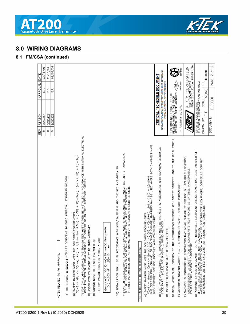
AT200-0200-1 Rev k (10-2010) DCN0528 30
8.1 FM/CSA (continued)
8.0 WIRING DIAGRAMS

8.2 ATEX/IEC
8.0 WIRING DIAGRAMS
AT200-0200-1 Rev k (10-2010) DCN0528 31

AT200-0200-1 Rev k (10-2010) DCN0528 32
8.2 ATEX/IEC (continued)
8.0 WIRING DIAGRAMS

8.3 Typical Loop Wiring Diagram
8.0 WIRING DIAGRAMS
AT200-0200-1 Rev k (10-2010) DCN0528 33

AT200-0200-1 Rev k (10-2010) DCN0528 34
8.4 Loop Powered TX Hookup /RI Dual Compartment Housing
8.0 WIRING DIAGRAMS

9.0 SIL Certificate
AT200-0200-1 Rev k (10-2010) DCN0528 35

AT200-0200-1 Rev k (10-2010) DCN0528 36
9.0 SIL Certificate

10.0 EU DECLARATION OF CONFORMITY
AT200-0200-1 Rev k (10-2010) DCN0528 37
AT200-0200-1 Rev k (10-2010) DCN0528 38
11.0 WARRANTY STATEMENT
5 YEAR WARRANTY FOR: KM26 Magnetic Liquid Level Gauges; MagWave Dual Chamber System; LS Series Mechanical Level Switches (LS500, LS550, LS600, LS700, LS800 & LS900); EC External Chambers, STW Stilling Wells and ST95 Seal Pots. 3 YEAR WARRANTY FOR: KCAP300 & KCAP400 capacitance switches. Beta temperature and pressure switches (excluding wetted parts.) 2 YEAR WARRANTY FOR: AT100, AT100S and AT200 series transmitters; RS80 and RS85 liquid vibrating fork switches; RLT100 and RLT200 reed switch level transmitters; TX, TS, TQ, IX and IM thermal dispersion switches; IR10 and PP10 External Relays; MT2000, MT5000, MT5100 and MT5200 radar level transmitters; RI100 Repeat Indicators; KP paddle switches; A02, A75 & A77 RF capacitance level switches and A38 RF capacitance level transmitters; Buoyancy Level Switches (MS50, MS10, MS8D & MS8F); Magnetic Level Switches (MS30, MS40, MS41, PS35 & PS45). 1 YEAR WARRANTY FOR: KM50 gauging device; AT500 and AT600 series transmitters; LaserMeter and SureShot series laser transmitters; LPM200 digital indicator; DPM100 digital indicators; APM100 analog indicators; KVIEW series digital indicators and controllers; SF50 and SF60 vibrating fork switches, KB Electro-Mechanical Continuous Measuring Devices, KSONIK ultrasonic level switches, transmitters & transducers. SPECIAL WARRANTY CONSIDERATIONS: K-TEK does not honor OEM warranties for items not manufactured by K-TEK (i.e. Palm Pilots). These claims should be handled directly with the OEM. K-TEK will repair or replace, at K-TEK‟s election, defective items which are returned to K-TEK by the original purchaser within the period specified above from the shipment date of the item and which is found, upon examination by K-TEK, to its satisfaction, to contain defects in materials or workmanship which arose only under normal use and service and which were not the result of either alterations, misuse, abuse, improper or inadequate adjustments, applications or servicing of the product. K-TEK’s warranty does not include onsite repair or services. Field service rates can be supplied on request. If a product is believed to be defective, the original purchaser shall notify K-TEK and request a Returned Material Authorization before returning the material to K-TEK, with transportation prepaid by the purchaser. (To expedite all returns/repairs from outside of the United States, consult K-TEK‟s customer service team ([email protected]) to determine an optimal solution for shipping method and turnaround time.) The product, with repaired or replaced parts, shall be returned to the purchaser at any point in the world with transportation prepaid by K-TEK for best-way transportation only. K-TEK is not responsible for expedited shipping charges. If the product is shipped to K-TEK freight collect, then it will be returned to the customer freight collect. If inspection by K-TEK does not disclose any defects in material or workmanship, K-TEK‟s normal charges for repair and shipment shall apply (minimum 250.00 USD). The materials of construction for all K-TEK products are clearly specified and it is the responsibility of the purchaser to determine the compatibility of the materials for the application. THE FOREGOING WARRANTY IS K-TEK'S SOLE WARRANTY AND ALL OTHER WARRANTIES EXPRESSED, IMPLIED, OR STATUTORY, INCLUDING ANY IMPLIED WARRANTY OF MERCHANTABILITY OF FITNESS FOR A PARTICULAR PURPOSE, ARE EXCLUDED AND NEGATED TO THE MAXIMUM EXTENT PERMITTED BY LAW. NO PERSON OR REPRESENTATIVE IS AUTHORIZED TO EXTEND ANY OTHER WARRANTY OR CREATE FOR K-TEK ANY OTHER LIABILITY IN CONNECTION WITH THE SALE OF K-TEK‟S PRODUCTS. THE REMEDIES SET FORTH IN THIS WARRANTY ARE EXCLUSIVE OF ALL OTHER REMEDIES AGAINST K-TEK. K-TEK SHALL NOT BE LIABLE FOR ANY CONSEQUENTIAL, INCIDENTAL, OR SPECIAL DAMAGES OF ANY KIND. K-TEK‟S SOLE OBLIGATION SHALL BE TO REPAIR OR REPLACE PARTS (FOUND TO BE DEFECTIVE IN MATERIALS OR WORKMANSHIP) WHICH ARE RETURNED BY THE PURCHASER TO K-TEK.

AT200-0200-1 Rev k (10-2010) DCN0528 39

AT200-0200-1 Rev k (10-2010) DCN0528 40