k-series manual
TRANSCRIPT

Bredal type K40 – K165
Bredal A/S
Website: www.bredal.com E-mail: [email protected]
Type K40 - K135 Vers. April 2007
English No. 02008002
Bredal Type K35, K40, K45, K62, K65, K75, K82, K85, K102, K105, K115, K135 & K165
Version 8– January 2011 Page no. 2 of 73
EU DECLARATION OF HARMONISATION
(Directive 89/392/EEC, Annex II, supplement A)
Manufacturer: BREDAL A/S Overgårdsvej 19,
DK-7120 Vejle, Denmark
Hereby declares that
BREDAL Type Serial number has been manufactured in accordance with the Machinery Directive (Directive 89/392/EEC) with amendments, and with national regulations. Only for Teejet500 control Cal. figure _____________________________
App. Rate cm3/pulse______________________
Pulses/100 metres _______________________
Computer no._____________________________
Valve type Danfoss
Bredal DK-7120 Vejle, Denmark 3rd August 2003

Bredal Type K35, K40, K45, K62, K65, K75, K82, K85, K102, K105, K115, K135 & K165
Version 8– January 2011 Page no. 3 of 73
I
1 Introduction 5
2 Road safety 5
3 Technical specifications 6
4 Safety 7
5 Drawbar and coupling 8
5.1 Power take-off shaft 8
5.2 Speed-related belt drive KB2 9
5.3 Engine-driven belt drive 9
6 Dosage principle (dosing by volume / forcible application by belt/shutter) 10
6.1 Adjusting application rate and dosing principle 10
6.2 Instructions for determining litre weight (additional equipment) 11
6.3 Using dosing table for various widths 12
6.4 Using ranges 15
6.5 Max. capacity per minute 16
7 Adjusting spreading – lime 17
7.1 Spreading lime 17
7.2 Spreading very damp lime with rewersing spread box 19
8 Spreading artificial fertiliser using 12-24 m discs 20
8.1 Headland spreading 12-16 m working width (additional equipment) 21
8.2 Headland spreading 18-24 m working width (additional equipment) 21
9 Adjusting for 12-36 m fertiliser application equipment (additional equipment) 22
9.1 Headland spreading 18-36 m working width (additional equipment) 23
9.2 Headland spreading with headland device 12-28 m (additional equipment) 24
9.3 Installation of 12-36 m fertiliser application equipment 25
10 Troubleshooting 26
11 Maintenance 28
11.1 Maintenance schedule for long-season spreaders 31
12 Fertiliser quality 37
13 Spreading test and adjustment of spreading 39
13.1 Spread test with 12-24 m (square discs) 40
13.2 Spread test with 12-36 m (round discs) 42
13.3 Performing a Spread Test and adjusting the spread pattern when using the headland kit. 43
14 Driving on residual widths, wedges and undulating terrain 44
15 Spreading special fertiliser using 12-36 m discs 48

Bredal Type K35, K40, K45, K62, K65, K75, K82, K85, K102, K105, K115, K135 & K165
Version 8– January 2011 Page no. 4 of 73
16 Extra equipment 51
16.1 Litre weight 51
16.2 Weight transfer 52
16.3 Sand/salt equipment 53
16.4 Top dressing with SPC4500 reversed spreading system 53
16.5 Conveyor Fejl! Bogmærke er ikke defineret.
16.6 Late fertilising 55

Bredal Type K35, K40, K45, K62, K65, K75, K82, K85, K102, K105, K115, K135 & K165
Version 8– January 2011 Page no. 5 of 73
1 Introduction
BREDAL type K35 – K135 machines are designed to spread dry, granulated material with no dust content on agricultural areas.
It is the operator’s responsibility to ensure that the machines are only used to spread materials that do not damage their own or others’ health and property. The machines may only be used and maintained by people who can be informed of the fact that such machines can be dangerous and who understand this.
The type plate specifies the machine type (K35 – K135), the serial number and the year of manufacture. The maximum gross weight and net weight are also included. The difference be-tween these gives the permitted payload. For K35 – K135, the gross weight is specified for the tyre type with which the machine was fitted at the factory. If the tyres are changed or addi-tional wheels are mounted, the user is responsible for ensuring that these can withstand the load from the machine gross weight.
This instruction book contains recommended settings for spreading commonly used artificial fertilisers. Fertiliser quality is not a constant factor. This varies from year to year and from batch to batch. BREDAL A/S therefore cannot be held responsible for spreading quality. This applies in relation to the fertiliser and also to spare parts and their installation.
The user is solely responsible for ensuring that the machine functions in such a way that it achieves acceptable results. BREDAL A/S carries out continuous testing of fertiliser types available on the market. If you are in any doubt about the spreadability of the fertiliser type, please contact the factory. A simple way of checking spreading quality is to carry out a spreading test in the field
(cf. section 12.1).
Issues to consider Each year, your spreader applies several times its own value in fertiliser. The effect of a few bad jobs due to a lack of maintenance, poor quality fertiliser or an operating error can result in loss of yield, which can exceed investment in the machine many times over.
Remember this when buying fertiliser, purchasing a spreader and during maintenance.
2 Road safety iWhen driving on public roads it is important to obey road safety regulations.
Check that: 1. lights are in working order and connected to the tractor’s light sockets, and that lights are cleaned after each
spreading task. 2. warning triangles are in working order and clean. 3. nuts on drawbars and wheels are tightened using the correct torque. 4. the tyre pressure is correct. 5. there are no cracks on shafts, tyres and rims.
6. the pegs in the drawbar are of the proper diameter and are locked.

Bredal Type K35, K40, K45, K62, K65, K75, K82, K85, K102, K105, K115, K135 & K165
Version 8– January 2011 Page no. 6 of 73
3 Technical specifications K40 K45 K62 K65 K75 K82 Net weight 1,400 kg 1,600 kg 2,000 kg 2,000 kg 2,000 kg 2,800 kg
Capacity 2.5 m3 3.5 m3 5.0 m³ 5.0 m³ 5.8 m³ 6.0 m³
- with extension 3.6 m3 4.8 m3 6.5 m3 6.5 m3 ****** 8.0 m³
Load capacity 4 tonnes 5 tonnes 7 tonnes 7 tonnes 6.4 tonnes
Wheel size 425/65 x 22.5 16.9 x 30/8 PR 550/60 x 22.5 23.1 x 26 Only as 23.1 x 26
Option 2 500/65 x 15.5 550/60 x 22.5 600/55 x 26.5 28 x 26 unit 650/65 x 30.5
Option 3 16.9 x 30 500/60 x 26.5 700/50 x 26.5 650/65 x 30..5 750/65 x 30.5
23.1 x 26 600/55 x 26.5 800/65 x 32
23.1 x 26
Hopper length 280 cm 290 cm 215 cm 215 cm 395 cm 395 cm Hopper width 185 cm 195 cm 225 cm 225 cm 215 cm 215 cm Loading height approx.
175 cm 190 cm 255 cm 255 cm 210 cm 230 cm
Total length 520 cm 525 cm 525 cm 525 cm 620 cm 620 cm Maximum width 235 cm 255 cm 255 cm 255 cm 265 cm 265 cm Standard trans-mission
SPC4500-1 SPC4500-1 SPC4500-1 SPC4500-1 SPC4500-2 SPC4500-2
K85 K102 K105 K125 K135
Net weight 2800 kg 3200 kg 3200 kg 6500 kg 7600 kg
Capacity 6,6 m3 7,6 m3 9 m3 11,3 m3
13 m3
- with extension 8,5 m3 9,2 m3 11,3 m3 14,3 m3 17 m3
Load capacity 10 tonnes 9,8 tonnes 12 tonnes 15 tonnes
20 tons
Wheel size 23.1 x 26 750/60 x 30.5 750/60 x 30.5 Only as unit 650/60 x 30.5
Option 2 800/65 x 32 800/65 x 32 800/65 x 32 750/60 x 30.5
Option 3 30.5 x 32 Russ
30.5 x 32 Russ 30.5 x 32 Russ
Hopper length 395 cm 506 cm 410 cm 506 cm 578 cm
Hopper width 215 cm 185 cm 245 cm 245 cm 245 cm
Loading height approx. 230 cm 245 cm 255 cm 245 cm 275 cm
Total length 620 cm 620 cm 620 cm 780 cm 874 cm
Maximum width 265 cm 295 cm 295 cm 290 cm
Standard transmission SPC4500-2 SPC4500-2 SPC4500-2 SPC4500-2 SPC4500-2
Spreading capacity Capacity 10 m spreading width 16 m working width SPC4500-1 1.0 t/min. 5 t/ha 3 t/ha SPC4500-2 1.5 t/min. 8 t/ha 5 t/ha At 10 km/h
Lime Fertiliser
Revs per minute of power take-off when spreading 540 rpm. 450 - 1000 rpm.
Bredal Type K35, K40, K45, K62, K65, K75, K82, K85, K102, K105, K115, K135 & K165
Version 8– January 2011 Page no. 7 of 73
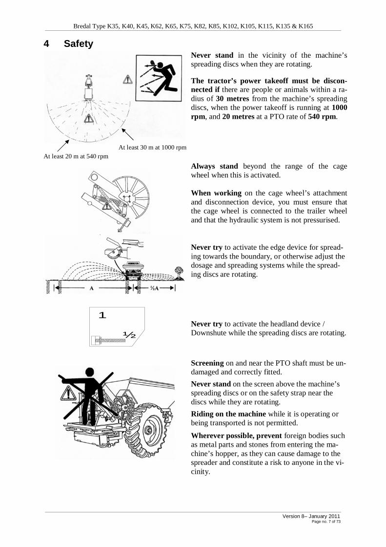
4 Safety
Never stand in the vicinity of the machine’s spreading discs when they are rotating.
The tractor’s power takeoff must be discon-nected if there are people or animals within a ra-dius of 30 metres from the machine’s spreading discs, when the power takeoff is running at 1000 rpm, and 20 metres at a PTO rate of 540 rpm.
At least 30 m at 1000 rpm At least 20 m at 540 rpm
Always stand beyond the range of the cage wheel when this is activated. When working on the cage wheel’s attachment and disconnection device, you must ensure that the cage wheel is connected to the trailer wheel and that the hydraulic system is not pressurised.
Never try to activate the edge device for spread-ing towards the boundary, or otherwise adjust the dosage and spreading systems while the spread-ing discs are rotating.
½
1
Never try to activate the headland device / Downshute while the spreading discs are rotating.
Screening on and near the PTO shaft must be un-damaged and correctly fitted.
Never stand on the screen above the machine’s spreading discs or on the safety strap near the discs while they are rotating.
Riding on the machine while it is operating or being transported is not permitted.
Wherever possible, prevent foreign bodies such as metal parts and stones from entering the ma-chine’s hopper, as they can cause damage to the spreader and constitute a risk to anyone in the vi-cinity.
Bredal Type K35, K40, K45, K62, K65, K75, K82, K85, K102, K105, K115, K135 & K165
Version 8– January 2011 Page no. 8 of 73
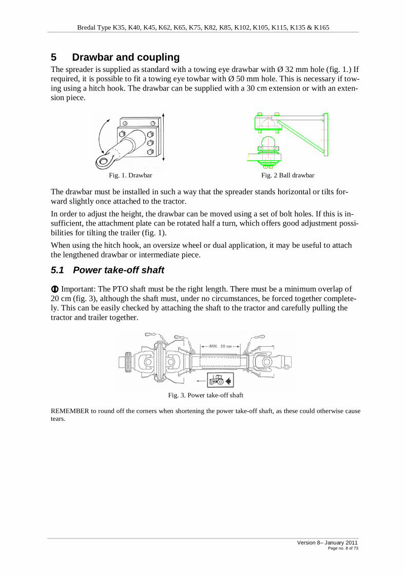
5 Drawbar and coupling The spreader is supplied as standard with a towing eye drawbar with Ø 32 mm hole (fig. 1.) If required, it is possible to fit a towing eye towbar with Ø 50 mm hole. This is necessary if tow-ing using a hitch hook. The drawbar can be supplied with a 30 cm extension or with an exten-sion piece.
Fig. 1. Drawbar Fig. 2 Ball drawbar
The drawbar must be installed in such a way that the spreader stands horizontal or tilts for-ward slightly once attached to the tractor.
In order to adjust the height, the drawbar can be moved using a set of bolt holes. If this is in-sufficient, the attachment plate can be rotated half a turn, which offers good adjustment possi-bilities for tilting the trailer (fig. 1).
When using the hitch hook, an oversize wheel or dual application, it may be useful to attach the lengthened drawbar or intermediate piece.
5.1 Power take-off shaft
i Important: The PTO shaft must be the right length. There must be a minimum overlap of 20 cm (fig. 3), although the shaft must, under no circumstances, be forced together complete-ly. This can be easily checked by attaching the shaft to the tractor and carefully pulling the tractor and trailer together.
Fig. 3. Power take-off shaft
REMEMBER to round off the corners when shortening the power take-off shaft, as these could otherwise cause tears.
Bredal Type K35, K40, K45, K62, K65, K75, K82, K85, K102, K105, K115, K135 & K165
Version 8– January 2011 Page no. 9 of 73
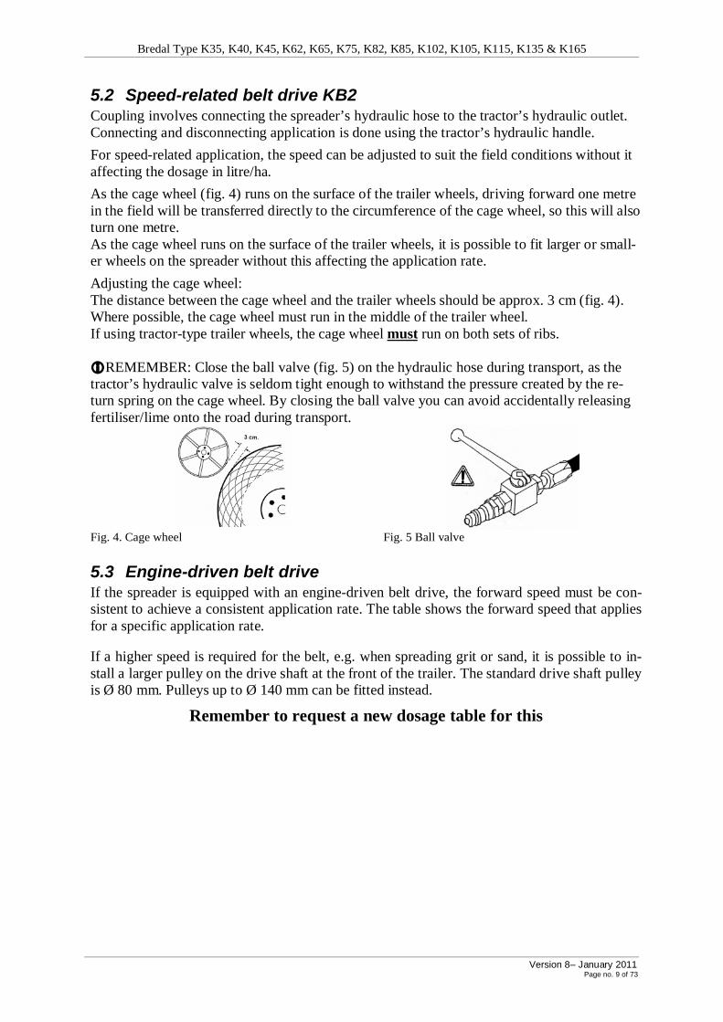
5.2 Speed-related belt drive KB2 Coupling involves connecting the spreader’s hydraulic hose to the tractor’s hydraulic outlet. Connecting and disconnecting application is done using the tractor’s hydraulic handle.
For speed-related application, the speed can be adjusted to suit the field conditions without it affecting the dosage in litre/ha.
As the cage wheel (fig. 4) runs on the surface of the trailer wheels, driving forward one metre in the field will be transferred directly to the circumference of the cage wheel, so this will also turn one metre. As the cage wheel runs on the surface of the trailer wheels, it is possible to fit larger or small-er wheels on the spreader without this affecting the application rate.
Adjusting the cage wheel: The distance between the cage wheel and the trailer wheels should be approx. 3 cm (fig. 4). Where possible, the cage wheel must run in the middle of the trailer wheel. If using tractor-type trailer wheels, the cage wheel must run on both sets of ribs. iREMEMBER: Close the ball valve (fig. 5) on the hydraulic hose during transport, as the tractor’s hydraulic valve is seldom tight enough to withstand the pressure created by the re-turn spring on the cage wheel. By closing the ball valve you can avoid accidentally releasing fertiliser/lime onto the road during transport.
Fig. 4. Cage wheel Fig. 5 Ball valve
5.3 Engine-driven belt drive If the spreader is equipped with an engine-driven belt drive, the forward speed must be con-sistent to achieve a consistent application rate. The table shows the forward speed that applies for a specific application rate.
If a higher speed is required for the belt, e.g. when spreading grit or sand, it is possible to in-stall a larger pulley on the drive shaft at the front of the trailer. The standard drive shaft pulley is Ø 80 mm. Pulleys up to Ø 140 mm can be fitted instead.
Remember to request a new dosage table for this

Bredal Type K35, K40, K45, K62, K65, K75, K82, K85, K102, K105, K115, K135 & K165
Version 8– January 2011 Page no. 10 of 73
6 Dosage principle (dosing by volume / forcible application by belt/shutter) Bredal K-spreaders are designed with forcible application and adjustable shutters (dosage doors) and a wide belt in the base of the hopper which forcibly applies the fertiliser.
The application rate (the belt speed) is speed-related, and standard application is driven by a cage wheel (KB-2) which is connected to the spreader’s wheels. The forward speed is there-fore optional. Forcible application means that you only need to adjust the litre weight of the fertiliser to adjust the spreader.
6.1 Adjusting application rate and dosing principle BREDAL spreaders are equipped with 2 large spreading discs, which are geared at 11% in re-lation to the PTO shaft. This means that the fertiliser is applied at a high speed. At a shaft speed of 540 rpm, the application rate is approx. 140 km/h and at 1000 rpm approx. 250 km/h. In order for the fertiliser to be able to withstand the load to which it is subjected, it must be able to withstand a pressure of at least 0.5 – 1 kg at 540 rpm, 2 kg at 800 rpm and 3 – 4 kg at 1000 rpm.
Fig. 6 Spreading disc overlap Fig. 7 Correct double overlap
The high speed means that common fertiliser types are always applied over a spreading width that is at least twice the working width. This is also called double overlapping (fig. 6). The spread pattern covers an area of 1,000 – 2,000m² when spread at 1,000 rpm, so the concentra-tion of fertiliser per m² is extremely small.
A triangular-shaped spreading curve with double overlapping (fig. 7) always produces great flexibility as regards variations in the working width, number of revolutions, etc. The high speed of the fertiliser (up to 250 km/h) means the wind has less of an effect. By way of com-parison, a sharp gust of wind has a speed of approx. 40 km/h (approx. 11 m/s).

Bredal Type K35, K40, K45, K62, K65, K75, K82, K85, K102, K105, K115, K135 & K165
Version 8– January 2011 Page no. 11 of 73
6.2 Instructions for determining litre weight (additional equipment) A prerequisite for using the dosing table is that you know exactly how much fertiliser in kg/ha must be spread and the volume weight (litre weight) in kg/litre for the fertiliser type.
In order to determine the correct setting, the litre weight (kg/litre) of fertiliser is divided by the desired dosage. Example 400 kg/ha Litre weight 1.08 kg/litre
haliterliterkg
hakg/ 370
/ 08,1
/ 400=
Find the spreading width required. Example where 370 litres/ha is to be spread over a work-ing width of 12 metres. Find 370 or the figure nearest to it in the dosing table. Now read off the setting from the table.
Instructions for using litre weight – cf. section 47

Bredal Type K35, K40, K45, K62, K65, K75, K82, K85, K102, K105, K115, K135 & K165
Version 8– January 2011 Page no. 12 of 73
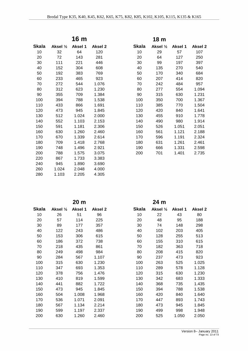
6.3 Using dosing table for various widths In order to determine the correct setting, the litre weight (kg/litre) of fertiliser is divided by the desired dosage. You can then find the number of litres/ha in the dosing table. The range table, for which instructions are given on page 14, may also be used.
Example • 600 kg/ha • Litre weight 1.10 kg kg/liter 10.1
kg/ha 600=545 litres/ha (now set to 545 in dosing table).
12 m 15 m
Skala Aksel ½ Aksel 1 Aksel 2 Skala Aksel ½ Aksel 1 Aksel 2 10 43 85 160 10 34 68 128 20 95 190 375 20 76 152 300 30 148 295 595 30 118 236 476 40 203 405 810 40 162 324 648 50 255 510 1.025 50 204 408 820 60 310 620 1.230 60 248 496 984 70 363 725 1.435 70 290 580 1.148 80 415 830 1.640 80 332 664 1.312 90 473 945 1.845 90 378 756 1.476
100 525 1.050 2.050 100 420 840 1.640 110 578 1.155 2.255 110 462 924 1.804 120 630 1.260 2.460 120 504 1.008 1.968 130 683 1.365 2.665 130 546 1.092 2.132 140 735 1.470 2.870 140 588 1.176 2.296 150 788 1.575 3.075 150 630 1.260 2.460 160 840 1.680 3.280 160 672 1.344 2.624 170 893 1.785 3.485 170 714 1.428 2.788 180 945 1.890 3.690 180 756 1.512 2.952 190 998 1.995 3.895 190 798 1.596 3.116 200 1.050 2.100 4.100 200 840 1.680 3.280 220 1.155 2.310 4.510 220 924 1.848 3.608 240 1.260 2.520 4.920 240 1.008 2.016 3.936 260 1.365 2.730 5.330 260 1.092 2.184 4.264 280 1.470 2.940 5.740 280 1.176 2.352 4.592
Bredal Type K35, K40, K45, K62, K65, K75, K82, K85, K102, K105, K115, K135 & K165
Version 8– January 2011 Page no. 13 of 73
16 m 18 m
Skala Aksel ½ Aksel 1 Aksel 2 Skala Aksel ½ Aksel 1 Aksel 2 10 32 64 120 10 29 57 107 20 72 143 281 20 64 127 250 30 111 221 446 30 99 197 397 40 152 304 608 40 135 270 540 50 192 383 769 50 170 340 684 60 233 465 923 60 207 414 820 70 272 544 1.076 70 242 484 957 80 312 623 1.230 80 277 554 1.094 90 355 709 1.384 90 315 630 1.231
100 394 788 1.538 100 350 700 1.367 110 433 866 1.691 110 385 770 1.504 120 473 945 1.845 120 420 840 1.641 130 512 1.024 2.000 130 455 910 1.778 140 552 1.103 2.153 140 490 980 1.914 150 591 1.181 2.306 150 526 1.051 2.051 160 630 1.260 2.460 160 561 1.121 2.188 170 670 1.339 2.614 170 596 1.191 2.324 180 709 1.418 2.768 180 631 1.261 2.461 190 748 1.496 2.921 190 666 1.331 2.598 200 788 1.575 3.075 200 701 1.401 2.735 220 867 1.733 3.383 240 945 1.890 3.690 260 1.024 2.048 4.000 280 1.103 2.205 4.305
20 m 24 m
Skala Aksel ½ Aksel 1 Aksel 2 Skala Aksel ½ Aksel 1 Aksel 2 10 26 51 96 10 22 43 80 20 57 114 225 20 48 95 188 30 89 177 357 30 74 148 298 40 122 243 486 40 102 203 405 50 153 306 615 50 128 255 513 60 186 372 738 60 155 310 615 70 218 435 861 70 182 363 718 80 249 498 984 80 208 415 820 90 284 567 1.107 90 237 473 923
100 315 630 1.230 100 263 525 1.025 110 347 693 1.353 110 289 578 1.128 120 378 756 1.476 120 315 630 1.230 130 410 819 1.599 130 342 683 1.333 140 441 882 1.722 140 368 735 1.435 150 473 945 1.845 150 394 788 1.538 160 504 1.008 1.968 160 420 840 1.640 170 536 1.071 2.091 170 447 893 1.743 180 567 1.134 2.214 180 473 945 1.845 190 599 1.197 2.337 190 499 998 1.948 200 630 1.260 2.460 200 525 1.050 2.050

Bredal Type K35, K40, K45, K62, K65, K75, K82, K85, K102, K105, K115, K135 & K165
Version 8– January 2011 Page no. 14 of 73
28 m 30 m
Skala Aksel ½ Aksel 1 Aksel 2 Skala Aksel ½ Aksel 1 Aksel 2 10 18 36 69 10 17 34 64 20 41 82 161 20 38 76 150 30 64 127 255 30 59 118 238 40 87 174 347 40 81 162 324 50 110 219 440 50 102 204 410 60 133 266 528 60 124 248 492 70 156 311 616 70 145 290 574 80 178 356 704 80 166 332 656 90 203 405 792 90 189 378 738
100 225 450 879 100 210 420 820 110 248 495 967 110 231 462 902 120 270 540 1.054 120 252 504 984 130 293 585 1.140 130 273 546 1.066 140 315 630 1.230 140 294 588 1.148 150 338 675 1.318 150 315 630 1.230 160 360 720 1.405 160 336 672 1.312 170 383 765 1.494 170 357 714 1.394
32 m 36 m
Skala Aksel ½ Aksel 1 Aksel 2 Skala Aksel ½ Aksel 1 Aksel 2 10 16 32 60 10 14 28 53 20 36 71 141 20 32 63 125 30 56 111 223 30 49 98 198 40 76 152 304 40 68 135 270 50 96 191 384 50 85 170 341 60 117 233 461 60 103 206 410 70 136 272 538 70 121 241 478 80 156 311 615 80 138 276 545 90 177 354 692 90 158 315 614
100 197 394 769 100 175 350 683 110 217 433 846 110 193 385 751 120 237 473 923 120 210 420 819
130 256 512 999 130 228 455 887 140 276 551 1.076 140 245 490 956 150 296 591 1.153 150 262 524 1.024 160 315 630 1.230 160 280 559 1.092 170 357 714 1.307 170 297 594 1.161
Bredal Type K35, K40, K45, K62, K65, K75, K82, K85, K102, K105, K115, K135 & K165
Version 8– January 2011 Page no. 15 of 73
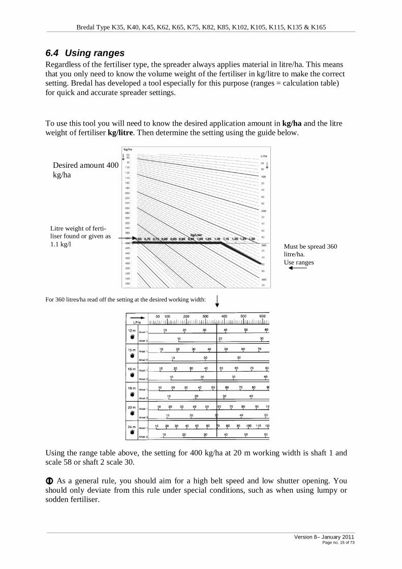
6.4 Using ranges Regardless of the fertiliser type, the spreader always applies material in litre/ha. This means that you only need to know the volume weight of the fertiliser in kg/litre to make the correct setting. Bredal has developed a tool especially for this purpose (ranges = calculation table) for quick and accurate spreader settings.
To use this tool you will need to know the desired application amount in kg/ha and the litre weight of fertiliser kg/litre. Then determine the setting using the guide below.
For 360 litres/ha read off the setting at the desired working width:
Using the range table above, the setting for 400 kg/ha at 20 m working width is shaft 1 and scale 58 or shaft 2 scale 30. i As a general rule, you should aim for a high belt speed and low shutter opening. You should only deviate from this rule under special conditions, such as when using lumpy or sodden fertiliser.
Desired amount 400 kg/ha
Litre weight of ferti-liser found or given as 1.1 kg/l Must be spread 360
litre/ha. Use ranges
Bredal Type K35, K40, K45, K62, K65, K75, K82, K85, K102, K105, K115, K135 & K165
Version 8– January 2011 Page no. 16 of 73
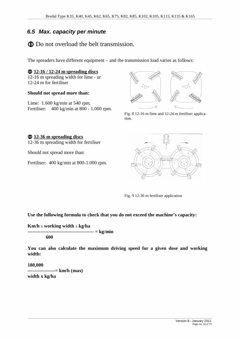
6.5 Max. capacity per minute
i Do not overload the belt transmission.
The spreaders have different equipment – and the transmission load varies as follows: i 12-16 / 12-24 m spreading discs 12-16 m spreading width for lime - or 12-24 m for fertiliser
Should not spread more than:
Lime: 1.600 kg/min at 540 rpm. Fertiliser: 400 kg/min at 800 - 1.000 rpm. Fig. 8 12-16 m lime and 12-24 m fertiliser applica-
tion.
i 12-36 m spreading discs 12-36 m spreading width for fertiliser
Should not spread more than:
Fertiliser: 400 kg/min at 800-1.000 rpm.
Fig. 9 12-36 m fertiliser application
Use the following formula to check that you do not exceed the machine’s capacity: Km/h x working width x kg/ha ----------------------------------------- = kg/min 600 You can also calculate the maximum driving speed for a given dose and working width: 180,000 -----------------= km/h (max) width x kg/ha

Bredal Type K35, K40, K45, K62, K65, K75, K82, K85, K102, K105, K115, K135 & K165
Version 8– January 2011 Page no. 17 of 73
7 Adjusting spreading – lime
Check regularly that the spreading system is in working order. If vital parts are damaged, this may seriously affect spreading accuracy.
When spreading in poor weather or when using damp fertiliser, clean the Downshute carrying the fertiliser from the conveyor to the spreading discs frequently. Blockages in the Downshutes will affect spreading accuracy.
7.1 Spreading lime The spreading discs for lime and the Downshute must be fitted when spreading lime (fig. 8). i Detach: Divider, sieve and the top discs above the spreading discs for spreading lime.
i Move the adjustable arms to setting 110, (scale B).
Adjusting for spreading lime, 12-16 m
A
Scale B
12 - 16 m 540 rpm 110
Fig. 10. Spreading system seen from the right with adjust-able arm scale.
Fig. 11 Adjustable arm (right side) seen from above
The working width is altered by moving the spreading system in and out. This is done by loosening bolt A and then altering the accompanying shaft and the holes D on scale setting B.
iIt is important to use good-quality lime. Damp lime and lime that contains large stones, turf and lumps will block the Downshute (if this cannot be opened, refer to section 7.2).
Maximum output per minute: Do not overload the belt transmission. Where the spreader is equipped with 12-16 m lime spreading discs do not apply more than: 1,600 kg lime/min at 540 rpm.
Fig. 12. 12-24 m spreading discs (lime discs).
iRemember that spreading discs used to spread lime should not be used to spread artificial fertiliser. For spreading artificial fertiliser Bredal instead recommends fertiliser equipment with associated discs, or 12-24 m spreading discs with circular discs for spreading artificial fertiliser (cf. section 7.3).

Bredal Type K35, K40, K45, K62, K65, K75, K82, K85, K102, K105, K115, K135 & K165
Version 8– January 2011 Page no. 18 of 73
General precautions for adjusting lime spreading When spreading lime it is possible to adjust the settings to achieve optimum application.
If there is too much lime between the tracks (fig. 13)
Fig. 13 Gauge glass: Too much lime between the tracks
12-16 m: Adjust the spreading system away from the tractor (scale B produces a larger val-ue). If there is too much lime behind the spreader (fig. 14).
Fig. 14 Gauge glass: Too much lime behind the spreader
12-16 m: Adjust the spreading system forward towards the tractor (scale B produces a smaller value). iREMEMBER: To tighten the adjustable arm after final adjustment. Additional information about how to adjust spreader to achieve satisfactory spreading may be found in section 12, “performing spreading tests”. In the event of irregularities during spreading, always check the following before performing a spreading test. There must not be any holes worn in the dischargers. Check that the correct settings are used for each working width.

Bredal Type K35, K40, K45, K62, K65, K75, K82, K85, K102, K105, K115, K135 & K165
Version 8– January 2011 Page no. 19 of 73
7.2 Spreading very damp lime with rewersing spread box If spreading sticky lime, etc. Bredal recommends that the machine be equipped with a re-verse gear and reversing spreading discs (additional equipment).
These spreading discs belonging to the reverse gear are painted yellow.
The reverse gear makes it possible to use the direction of rotation of the spreading discs. The yellow spreading discs where the discharge blades are used make it possible to spread sticky and damp lime.
The maximum working width for this equipment is 16 m.
Fig. 15. Reversed spreading discs for spreading lime.
Adjusting for spreading lime, 12-16 m
A Scale B
12 - 16 m 540 rpm 20 iRemember that this equipment is not intended for spreading artificial fertiliser. If spreading powdered lime or a similar material that cannot be spread with a normal spreading system, a hydraulic 12 m spreading screw can be supplied (for K85 model only).

Bredal Type K35, K40, K45, K62, K65, K75, K82, K85, K102, K105, K115, K135 & K165
Version 8– January 2011 Page no. 20 of 73
8 Spreading artificial fertiliser using 12-24 m discs
i For spreading artificial fertiliser, use: 12-24 m (fig. 16) or
12-36 m (fig. 9) spreading discs.
Bredal recommends 12-36 m fertiliser application equipment.
If using 12-24 m spreading discs for spreading artificial fertiliser, you should have 2 sets of spreading discs, 1 set for spreading lime and 1 set for spreading artificial fertiliser.
Adjusting 12-24 m spreading discs
Fig. 16. 12-24 m spreading discs for lime and artificial fertiliser.
Adjusting for spreading artificial fertiliser using 12-24 m spreading discs
A Scale B
Always circular
top discs
12 540 120 15 800 120 16 800 120 Always 18 800 120 20 1,000 110 24 1,000 110
Fig. 17. Spreading system seen from the right with adjustable arm scale.
Fig. 18 Adjustable arm (right side) seen from above
Distribution in the field is altered by moving the spreading system in and out. This is done by loosening bolt A and then scale setting B can be altered using the crowbar and the holes D.

Bredal Type K35, K40, K45, K62, K65, K75, K82, K85, K102, K105, K115, K135 & K165
Version 8– January 2011 Page no. 21 of 73
8.1 Headland spreading 12-16 m working width (additional equipment) For working widths of 12, 15 and 16 m, a limit plate is available, which is fitted on the side turning towards the boundary.
For 12-16 m headland spreading, the revolutions are reduced, cf. the table below, and the screen must be as close to the discs as possible. For 15 and 16 m working widths, the out-side of the screen must be as far from the discs as possible (fig. 19).
Fig. 19. 12-16 m headland spreading.
Headland spreading 12-16 m working width
A
12 m
400 rpm
15 m 500 rpm
16 m
540 rpm
8.2 Headland spreading 18-24 m working width (additional equipment)
The instructions in the general user guide (fig. 20) have been prepared with a view to achieving approx. 50% application at boundary edges. This applies for large grains D. When spreading fertiliser with a smaller grain size, the number of revolutions on the PTO shaft must be increased in relation to the table.
A
18 m 440 400 20 m 500 460 24 m 540 500
Fig. 20 Headland spreading 18-24 m

Bredal Type K35, K40, K45, K62, K65, K75, K82, K85, K102, K105, K115, K135 & K165
Version 8– January 2011 Page no. 22 of 73
9 Adjusting for 12-36 m fertiliser application equipment (additional equipment)
When spreading artificial fertiliser Bredal recommends that 12-36 m fertiliser application equipment is used.
Fig. 21. 12-36 m spreading discs
Adjusting 12-36 m fertiliser application equipment
A
Scale B
12 m 0 450
15 m 1 540
16 m 1 540
18 m 2.0 750
20 m 2.5 750 120 24 m 4 900*
28 m 4 1,000*
30 m 4.5 1,000*
32 m 5 1,000*
36 m 5.5 1,000*
The quality of fertiliser must meet the requirements set in section 11.
* Prilled fertiliser max 800 rpm
iWhen installing 12-36 m fertiliser application equipment scale B must always be at 120.
Fig. 22. Spreading system seen from the right with adjustable arm scale.
Fig. 23 Guide plates up Fig. 23a Headland gear
Bredal Type K35, K40, K45, K62, K65, K75, K82, K85, K102, K105, K115, K135 & K165
Version 8– January 2011 Page no. 23 of 73
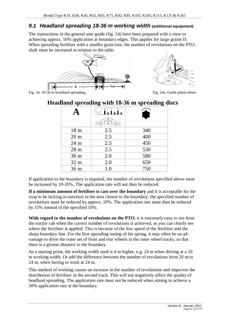
9.1 Headland spreading 18-36 m working width (additional equipment)
The instructions in the general user guide (fig. 24) have been prepared with a view to achieving approx. 50% application at boundary edges. This applies for large grains D. When spreading fertiliser with a smaller grain size, the number of revolutions on the PTO shaft must be increased in relation to the table.
Fig. 24. 18-36 m headland spreading. Fig. 24a. Guide plates down
Headland spreading with 18-36 m spreading discs
A
18 m 2.5 340 20 m 2.5 400 24 m 2.5 450 28 m 2.5 530 30 m 2.0 580 32 m 2.0 650 36 m 1.0 750
If application to the boundary is required, the number of revolutions specified above must be increased by 10-20%. The application rate will not then be reduced.
If a minimum amount of fertiliser is cast over the boundary and it is acceptable for the crop to be lacking in nutrition in the area closest to the boundary, the specified number of revolutions must be reduced by approx. 10%. The application rate must then be reduced by 15% instead of the specified 10%. With regard to the number of revolutions on the PTO, it is extremely easy to see from the tractor cab when the correct number of revolutions is achieved, as you can clearly see where the fertiliser is applied. This is because of the low speed of the fertiliser and the sharp boundary line. For the first spreading outing of the spring, it may often be an ad-vantage to drive the outer set of front and rear wheels in the inner wheel tracks, so that there is a greater distance to the boundary.
As a starting point, the working width used is 4 m higher, e.g. 24 m when driving at a 20 m working width. Or add the difference between the number of revolutions from 20 m to 24 m, when having to work at 24 m.
This method of working causes an increase in the number of revolutions and improves the distribution of fertiliser in the second track. This will not negatively affect the quality of headland spreading. The application rate must not be reduced when aiming to achieve a 50% application rate at the boundary.

Bredal Type K35, K40, K45, K62, K65, K75, K82, K85, K102, K105, K115, K135 & K165
Version 8– January 2011 Page no. 24 of 73
9.2 Headland spreading with headland device 12-28 m (additional equipment)
The spreader can be supplied with a device for headland spreading (additional equipment). The device is positioned below the left spreading disc. Drive with the left side towards the boundary. Use the revolutions shown in the table below.
Fig. 25. Headland spreading
Once the headland device is activated, there is roughly a 50% reduction in the revolution rate of the left spreading disc the right spreading disc continues at full speed into the field (fig. 25).
In order to adjust the spreader for headland spreading, the speed selector on the spreading box must be moved to the horizontal position (fig. 26) and the shaft on the Downshute must be activated so that the handle is vertical (fig. 27). The spreading discs must NOT be rotating when switching from spreading in the field to headland spreading.
½
1
Fig. 26. Handle for activating headland device Fig. 27. 12-36 m Downshute with guide plates for headland
spreading.
1 = Full spreading width, spreading in the field ½ = The headland device is activated for headland spreading.
Adjusting for 12-28 m headland spreading with headland device
A ½
1
12 m ½ 450
15 m ½ 500
16 m ½ 540
18 m ½ 600 Guide plates
20 m ½ 700 down
24 m ½ 900
28 m ½ 1000
Note that the handle MUST be at ½ for headland spreading
If the spreader is supplied with a hydraulic shift for headland spreading, a double-action hydraulic outlet is used on the tractor to activate/deactivate headland spreading.
If you require full application to a boundary, the number of revolutions in the table must be increased by approx. 50-100 rpm. If you must not spread over a boundary, reduce the number of revolutions in the table by 50-150 rpm. Headland device for 30-36 metres – refer to special instructions.
Bredal Type K35, K40, K45, K62, K65, K75, K82, K85, K102, K105, K115, K135 & K165
Version 8– January 2011 Page no. 25 of 73
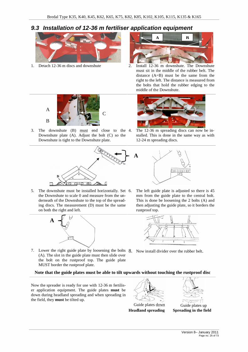
9.3 Installation of 12-36 m fertiliser application equipment
1. Detach 12-36 m discs and downshute 2. Install 12-36 m downshute. The Downshute
must sit in the middle of the rubber belt. The distance (A=B) must be the same from the right to the left. The distance is measured from the bolts that hold the rubber edging to the middle of the Downshute.
3. The downshute (B) must end close to the
Downshute plate (A). Adjust the bolt (C) so the Downshute is tight to the Downshute plate.
4. The 12-36 m spreading discs can now be in-stalled. This is done in the same way as with 12-24 m spreading discs.
5. The downshute must be installed horizontally. Set the Downshute to scale 0 and measure from the un-derneath of the Downshute to the top of the spread-ing discs. The measurement (D) must be the same on both the right and left.
6. The left guide plate is adjusted so there is 45 mm from the guide plate to the central bolt. This is done be loosening the 2 bolts (A) and then adjusting the guide plate, so it borders the rustproof top.
7. Lower the right guide plate by loosening the bolts
(A). The slot in the guide plate must then slide over the bolt on the rustproof top. The guide plate MUST border the rustproof plate.
8. Now install divider over the rubber belt.
Note that the guide plates must be able to tilt upwards without touching the rustproof disc
Now the spreader is ready for use with 12-36 m fertilis-er application equipment. The guide plates must be down during headland spreading and when spreading in the field, they must be tilted up.
Guide plates down
Guide plates up
Headland spreading Spreading in the field
A B
A
A
B
C
A

Bredal Type K35, K40, K45, K62, K65, K75, K82, K85, K102, K105, K115, K135 & K165
Version 8– January 2011 Page no. 26 of 73
10 Troubleshooting • Spreading blades must be correctly installed on the spreading discs. • Incorrectly-installed blades can produce huge changes in spreading.
iFor correct installation (refer to the drawings)
Fig. 28. 12-36 m spreading discs for artificial fertiliser Fig. 12-24 m spreading discs for lime and artificial
fertiliser
i Responsibility i
Defective and badly worn dischargers must be replaced. Perforated dischargers noticeably affect spreading. Correct installation of spreading discs and spreading blades is SOLELY the responsibility of the user. For help adjusting spreading regularity, refer to “performing spreading tests and adjusting spreading”.
Incorrect application If the spreader is not applying fertiliser correctly for any reason, check the following in the order they appear:
Check that the litre weight of fertiliser is correct. For this you can read the weight directly off the litre weight (supplied as additional equipment - see page 47).
Check that the conversion from kg/ha to litre/ha is correct (see section 6.2).
Check that the cage wheel is running correctly on the spreading wheels.
Check that the rear hatch adjustment is correct. See fig. 25 – next page.
If none of the above work: Find out how large a section of one scale interval or how many scale intervals are affected.
Example: At a working width of 12 m, the machine is set to spread 405 litres/ha, equivalent to shaft 1, scale 40.
After having spread a few hectares, check that the machine is only spreading 355 litres/ha.
This is equivalent to scale 35. The difference is thus 5 mm on the scale.
Loosen the bolt holding the scale and increase this by 5 mm.
Retighten and set the rear hatch to scale 40.
The machine will now spread 405 litres/ha.
This adjustment will then fit into the whole extent of the scale.

Bredal Type K35, K40, K45, K62, K65, K75, K82, K85, K102, K105, K115, K135 & K165
Version 8– January 2011 Page no. 27 of 73
The rear hatch is adjusted at the factory according to the following procedure:
2 x 30 mm distance pieces, approx. 0.5 m long are positioned below the rear hatch on each side (fig. 30). The hatch is closed so that it rests gently on the two distance pieces. The scale is adjusted to 30.
Fig. 30. Adjustment points on rear hatch.
Downshute The downshute must be adjusted so that the plastic part only just touches the rubber belt on the back roller (see fig. 24), so that the fertiliser grain etc. does not run between the belt and plastic skin.
Fig. 31. Adjust-ing Downshute plate.
Fig. 32. Adjusting downshute. Fig. 33. Adjusting downshute height over spreading discs.
iWarning: When adjusting the Downshute, check that nothing other than the plastic skin (bolts, etc.) touches the rubber belt. If this happens, it could damage the belt.
The downshute (fig. 32) must sit in the middle of the rubber belt. The distance (A=B) must be the same from the right to the left. The distance is measured from the bolts that hold the rubber edging to the middle of the Downshute.
A B
Bredal Type K35, K40, K45, K62, K65, K75, K82, K85, K102, K105, K115, K135 & K165
Version 8– January 2011 Page no. 28 of 73
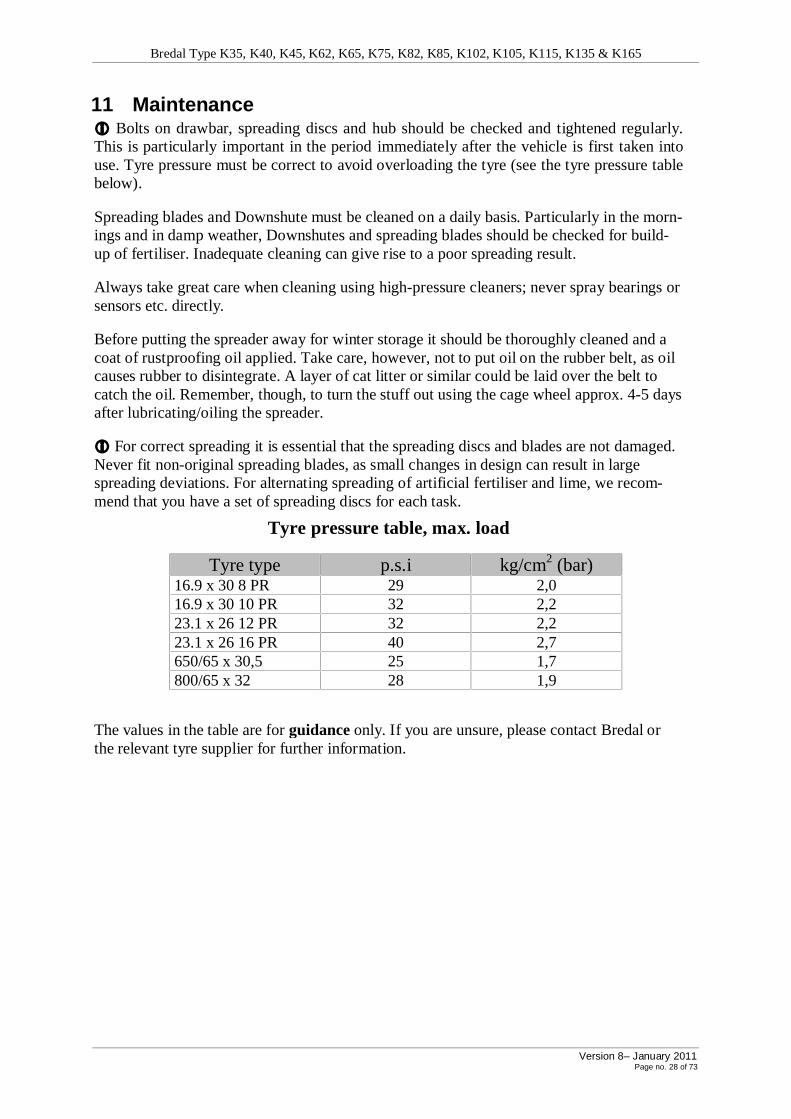
11 Maintenance i Bolts on drawbar, spreading discs and hub should be checked and tightened regularly. This is particularly important in the period immediately after the vehicle is first taken into use. Tyre pressure must be correct to avoid overloading the tyre (see the tyre pressure table below).
Spreading blades and Downshute must be cleaned on a daily basis. Particularly in the morn-ings and in damp weather, Downshutes and spreading blades should be checked for build-up of fertiliser. Inadequate cleaning can give rise to a poor spreading result.
Always take great care when cleaning using high-pressure cleaners; never spray bearings or sensors etc. directly.
Before putting the spreader away for winter storage it should be thoroughly cleaned and a coat of rustproofing oil applied. Take care, however, not to put oil on the rubber belt, as oil causes rubber to disintegrate. A layer of cat litter or similar could be laid over the belt to catch the oil. Remember, though, to turn the stuff out using the cage wheel approx. 4-5 days after lubricating/oiling the spreader. i For correct spreading it is essential that the spreading discs and blades are not damaged. Never fit non-original spreading blades, as small changes in design can result in large spreading deviations. For alternating spreading of artificial fertiliser and lime, we recom-mend that you have a set of spreading discs for each task.
Tyre pressure table, max. load
Tyre type p.s.i kg/cm2 (bar) 16.9 x 30 8 PR 29 2,0 16.9 x 30 10 PR 32 2,2 23.1 x 26 12 PR 32 2,2 23.1 x 26 16 PR 40 2,7 650/65 x 30,5 25 1,7 800/65 x 32 28 1,9
The values in the table are for guidance only. If you are unsure, please contact Bredal or the relevant tyre supplier for further information.

Bredal Type K35, K40, K45, K62, K65, K75, K82, K85, K102, K105, K115, K135 & K165
Version 8– January 2011 Page no. 29 of 73
Lubrication (KB2 and KB3 with cage wheel) Lubrication chart (see also fig. 34) K35 /
K40 K45 / K62
/ K65 K75 / K82
/ K85 K102 K105
K125 Lubricating Interval
Number of lubricating nipples Hours 1 Power take-off shaft 5 5 5 5 5 10
2 Drawbar 1 1 1 1 1 20
3 Stabiliser 1 1 1 1 1 20
4 Flange bearing for drive shaft (front) 2 2 4 4 4 20
5 Steering rollers 2 2 2 2 2 20
7 Wheel hub / brake toggle -/1 -/1 -/1 1/1 1/1 20
7a Link bogie (right/left) - - - - 8/8 20
8 Flange bearing for drive shaft (rear) 1 1 1 1 1 20
9 Power take-off 4 4 4 4 4 20
10 Bearing + cover for drawbar and snap roller
4+4 4+4 4+3 4+3 4+3 20
11 Input shaft at spreading box 1 1 1 1 1 20
12 Seal on disc hub 2 2 2 2 2 60
13 Groove between chain gear and back roller
1 1 1 1 1 60
14 Bearing chain gear KB2 1 1 1 1 1 20
14 Bearing chain gear KB3 4 4 4 4 4 20
15 Drive wheel, cylinder etc. 9 9 9 9 - 20
16 Power take-off 2 2 2 2 2 20
17 Seal at spline shaft 1 1 1 1 1 20
18 Handle / locking screw at rear hatch 2 2 2 2 2 20
• Oil levels on the closed two-gear chain drive and the chain drive at the cage wheel should be checked. The oil level must be such that the chain can reach the oil, but no more.
• Lubricate all screw threads used for adjusting the spreader often. As far as possible ad-justment bolts made of rustproof materials have been used. These should also be lubri-cated.
Fig. 34. Overview of places to lubricate.
Bredal Type K35, K40, K45, K62, K65, K75, K82, K85, K102, K105, K115, K135 & K165
Version 8– January 2011 Page no. 30 of 73
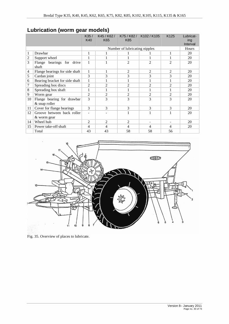
Lubrication (worm gear models) K35 /
K40 K45 / K62 /
K65 K75 / K82 /
K85 K102 / K105 K125 Lubricat-
ing Interval
Number of lubricating nipples Hours 1 Drawbar 1 1 1 1 1 20 2 Support wheel 1 1 1 1 1 20 3 Flange bearings for drive
shaft 1 1 2 2 2 20
4 Flange bearings for side shaft 1 1 2 2 2 20 5 Cardan joint 3 3 3 3 3 20 6 Bearing bracket for side shaft 1 1 1 1 1 20 7 Spreading box discs 2 2 2 2 2 20 8 Spreading box shaft 1 1 1 1 1 20 9 Worm gear 2 2 2 2 2 20 10 Flange bearing for drawbar
& snap roller 3 3 3 3 3 20
11 Cover for flange bearings 3 3 3 3 3 20 12 Groove between back roller
& worm gear - - 1 1 1 20
14 Wheel hub 2 2 2 - - 20 15 Power take-off shaft 4 4 4 4 4 20 Total 43 43 58 58 56
Fig. 35. Overview of places to lubricate.

Bredal Type K35, K40, K45, K62, K65, K75, K82, K85, K102, K105, K115, K135 & K165
Version 8– January 2011 Page no. 31 of 73
11.1 Maintenance schedule for long-season spreaders
Daily maintenance: Check:
1. Dischargers and discs for wear 2. Belt tension (pull the discs in the same direction) 3. Free passage for fertiliser in Downshute and sieves
Every 3 days or 20 operating hours and after high-pressure cleaning:
1. Lubrication as per the lubrication chart
Every month or after major cleaning: 1. Lubricate the spreader 2. Spray the spreader with neutral oil 3. REMEMBER – rubber cannot tolerate oil, so cover the belt with sand or sawdust
Winter storage: 1. Make the spreader look presentable (polishing, blast cleaning if necessary, and
(spot) painting). 2. Examine it for mechanical faults and setting errors. 3. Repair it (service engineer if necessary) 4. Spray it with neutral oil
Fitting and adjusting a rubber belt
i When fitting the belt, please remember it runs in the direction of the arrow i
1. Using a fork-lift truck or front loader, place the belt under the spreader.
2. Push the back roller into the rubber belt and…
3. fix it in place… … … ..
4. Fit the flange bearing on the right side.
5. Push the front roller into the rubber belt
6. Use the truck to lift the belt and set the front roller tighteners in together with the bracket for fit-ting the belt scraper.

Bredal Type K35, K40, K45, K62, K65, K75, K82, K85, K102, K105, K115, K135 & K165
Version 8– January 2011 Page no. 32 of 73
7. Fit bolts in the front roller bracket of the frame
8. and then tighten up the belt
9. Push the belt roller into the con-veyor belt (be extremely careful - the sharp edges can cut both the belt and your HAND!!).
10. Use the fork-lift truck to lift the belt roller frame
11. so the locking bolt of the belt roller frame is in position in the fixing brackets
Then loosen the belt again at the front belt tighteners (see picture no. 8)
12. Lift the snap roller (the belt tightener at the back roller) up into place
13. in the right and left suspension respectively
14. Adjust the distance from the ex-ternal frame in to the belt roller frame to obtain a centred position.
15. Adjust the belt frame so the belt roller runs vertically on the belt roller beds (see fig. 16).

Bredal Type K35, K40, K45, K62, K65, K75, K82, K85, K102, K105, K115, K135 & K165
Version 8– January 2011 Page no. 33 of 73
16. Adjust the belt roller frame so the right and left recesses sit at right angles to the belt frame profile in order to ensure the rollers run straight. (It is easiest to do this with a large set square)
17. Fit and adjust the belt scraper
18. Fit the conical belt guide Fasten/secure the belt roller frame and tighten up all belt roll-er bolts.
19. Fit the safety bracket on the left…
20. and right side respectively – and the fitting is finished.
Follow the instructions in reverse order to dismantle it.
The belt is equipped with a belt guide, consisting of two conical rollers just behind the front roller. These remove most fluctuations in the progress of the belt over the front roller.
It is possible to see the rubber belt on the front roller from the driver’s seat. If the rubber belt runs askew over the front roller for a long period it can be ruined.
Fig. 36. Fine adjustment of rubber belt
Make adjustments by turning the adjustment handle (picture 8) approx. ¼ turn, and then run it again briefly. The handle must be turned so that the belt becomes tighter on the side that the belt is running to, or loosened on the side that it must run to.

Bredal Type K35, K40, K45, K62, K65, K75, K82, K85, K102, K105, K115, K135 & K165
Version 8– January 2011 Page no. 34 of 73
If the belt runs askew, investigate whether:
§ The scraper is cleaning the front roller. § All belt rollers are turning.
§ Snap rollers (picture 13) are turning. § The belt frame is square (picture 16).
The belt must be adjusted so the belt rollers run perpendicularly on the rubber belt. Use a large set square or similar for the adjustment. Lay the set square down so it is flush with the edge of the channel bar profile and up to the mark – see picture 16.
Check that the set square lines up with the mark in the opposing channel bar profile. Adjust the adjuster bolt (5), and tighten the belt frame nuts.
Set the front and back rollers so they are straight in relation to the longitudinal shaft of the spreader. Change the position of the back roller by moving the chain gear forward or back (3). Adjust the front roller using the adjuster handle (1) and nut (2).
Set the front and back rollers during an empty trial run so that the belt runs straight in the trailer. This can be observed along the upper edge of the belt frame channel bar profiles (4) when you line them up from the front end of the spreader. The belt frame and belt should be roughly parallel.
Fitting the V-belt and tightening it
Check the V-belts regularly, particularly immediately after replacement. Check the tautness (fig. 46) by pressing one V-belt at a time between the two pulleys beneath the spreading discs. At a pressure of about 10 kg, the belts should give about 5-10 mm.
An easier way to check the tautness of the belts is to take hold of a blade on one of the spreading discs and a blade of the other disc in the other hand, and pull in the same direc-tion of rotation. Remember to tighten the nut on the tightening bracket (1) after finishing the tightening procedure.
Fitting and tightening V-belt.
Spreading system Number of V-belts SPC 4500-1 1.
Replacement of V-belt on SPC4500-1 with headland device
1. First unscrew the locking bolt be-
tween the transmission shaft and the fork shaft.
2. Loosen the spring and spring control and the bolts for the left and middle plastic bearing of the headland device.
3. Remove the headland device shaft
4. Remove the fork hold-ing the headland device in the right-hand plastic bearing
5. Remove the right-hand plastic bearing

Bredal Type K35, K40, K45, K62, K65, K75, K82, K85, K102, K105, K115, K135 & K165
Version 8– January 2011 Page no. 35 of 73
6. Loosen the belt tightener of the
headland device.
7. Remove the 2 lower V-belts on
the headland device
8. Remove the 2 upper V-belts on the headland device
9. Loosen the belt tighten-
er and remove the V-belt.
Fitting a new V-belt in reverse order
Remove the belt tightener (pulley 4 with bracket) before starting to fit the belt. On spreaders with two belts, these must be fitted at the same time.
1. Fit the belt on pulley 1 – the end must turn to the right. 2. Thread the upper part of the belt on pulley 1 behind pulley 2.
3. Twist the belt a half turn – thread it from pulley 2 to the rear disc of pulley 3.
4. Thread pulley 4 (the belt tightener) into the loose end of the belt between pulleys 1
and 3. Then attach the bracket to pulley 4 and tighten the belt using the belt tighten-er.
5. Fit the 2 upper V-belts on the headland device.
6. Fit the 2 lower V-belts on the headland device.
7. Tighten these using the headland device belt tightener.
8. Fit the fork that holds the headland device in its plastic bearing.
9. Push the headland device transmission shaft in over the fork shaft.
10. Fit the 2 other plastic bearings.
11. Fit spring and spring control.
12. Finally, screw the locking bolt between the transmission shaft and the fork shaft.

Bredal Type K35, K40, K45, K62, K65, K75, K82, K85, K102, K105, K115, K135 & K165
Version 8– January 2011 Page no. 36 of 73
Replacing a V-belt on SPC4500-2 Spreading system Number of V-belts
SPC 4500-2 2.
Fig. 37. Fitting and tightening V-belt.
Fitting new V-belts Remove the belt tightener (pulley 4 with bracket) before starting to fit the belt.
On spreaders with two belts, these must be fitted at the same time. 1. Fit the belt on pulley 1 – the end must turn to the right.
2. Thread the upper part of the belt on pulley 1 behind pulley 2.
3. Twist the belt a half turn. – Thread it from pulley 2 to the rear side of pulley 3. 4. Thread pulley 4 (the belt tightener) into the loose end of the belt between pulleys 1 and
3. Then attach the bracket to pulley 4 and tighten the belt.
6
5

Bredal Type K35, K40, K45, K62, K65, K75, K82, K85, K102, K105, K115, K135 & K165
Version 8– January 2011 Page no. 37 of 73
12 Fertiliser quality The quality of the fertiliser is crucial if the spreader is to work properly.
Gauging fertiliser quality To obtain a normative fertiliser quality, e.g. for purchase, to gain an impression of
spreading power, it is necessary to know the following values:
A. Grain strength can be gauged by placing one grain of fertiliser on an ordinary kitchen scale, and then pressing with increasing load on the grain, e.g. with the flat end of a pencil, while watching the scale’s display indicator. The weight that is displayed when the grain is crushed is an expression of the grain strength of the fertiliser. Make sure you test several grains (both large and small) and then calculate the average grain strength (fig. 38).
Fig. 38. Kitchen scale for gauging grain strength. B. Grain size can be measured using BREDAL’s sieve box. Fill the space above the sieve
with the largest grains. Put the lid on and shake until there are no more changes in distribution. Turn the box so the lid is again on top. Measure using a ruler or tape measure. Measure the number of mm in each space. Use normal proportional calculations to work out the % distribution in each space (fig.28).
Fig. 39. Sieve box for grain size
C. Litre weight can be measured using an ordinary litre measure or a 10-litre bucket. The greater the quantity, the more accurate the measurement. BREDAL can supply a beam scale for mounting on the spreader (fig. 29). This provides an immediate indication of the litre weight (instructions under point 6).
Fig. 40. Beam scale for determining litre weights D The shape of the grains can be assessed visually. The smoother and rounder a grain is,
the better it flies through the air and the better it runs out of the hopper. A sharp grain (broken) or a grain with a lot of nodules on its surface has poor flying properties, and will therefore have difficulty covering wider working widths.
E A high dust content can be assessed when calculating the grain size by there being a rel-atively large proportion of the fertiliser beneath the finest sieve. Dust content can often also be assessed visually.

Bredal Type K35, K40, K45, K62, K65, K75, K82, K85, K102, K105, K115, K135 & K165
Version 8– January 2011 Page no. 38 of 73
The effect of fertiliser quality on spreading properties A Low grain strength means that the fertiliser has a tendency to get crushed during
transport and spreading. There is often a close correlation between low grain strength and dust content, as fertilisers with low strength values are crushed during transport and stor-age. The grain strength of a batch of fertiliser is often satisfactory when it leaves the factory. If the fertiliser is exposed to high atmospheric humidity or direct water penetration during transport or storage, it loses its original grain strength.
This cannot be recovered even if the fertiliser batch is dried out. The fertiliser must there-fore always be covered with plastic during storage. Certain types of fertiliser always have low grain strength, particularly prilled urea and certain types of ammonium nitrate (N34). There are large fluctuations in grain strength between the various makes of urea and am-monium nitrate (N34).
These fluctuations occur when fertilisers are sensitive to crushing by the spreading discs.
Normal co-granulated fertiliser has a grain strength of 3 - 8 kg. Ammonium nitrate (N34) has a grain strength of 0.5 - 3 kg. Urea has a grain strength of 0.5 - 2 kg, while individual-ly granulated types of urea have a grain strength of approx. 3 kg. (To be able to with-stand the load of a BREDAL spreader with a power takeoff of 540 rpm, the mini-mum requirement is 0.5 - 1 kg. At a power takeoff of 800 rpm, the minimum re-quirement is approx. 2 kg, and at 1000 rpm it is 3 – 4 kg.
B Grain size is significant for how far the fertiliser can be thrown. Large fertiliser grains can be thrown further than small ones, so a minimum grain size requirement is necessary for application over large working widths. BREDAL sets a lower limit for average grain size of around 2.8 mm (20 – 28 m) and 3.1 mm (30 to 36 m). Using BREDAL’s sieve box, there must therefore be more than approx. 40% - 45% of the fertiliser above the 3 mm sieve (20-28 m) and approx. 55% or more above the 3 mm sieve (30-36 m).
Normal prilled and granulated fertilisers have average grain sizes of around 2.9 - 3.3 mm. Ammonium nitrate (N34) has an average grain size of approx. 2.0 – 2.8 mm. Prilled urea has an average grain size of 1.5 - 2.5 mm, while certain granulated urea makes can be 3 - 3.5 mm. A 12 m working width does not impose any special require-ments on grain size, although large quantities of dust in the fertiliser should be avoided, and the fertiliser must not resemble salt or sugar.
C Heavy fertiliser grains can be thrown further than light ones. A minimum requirement is
therefore necessary for the fertiliser’s specific weight for larger working widths. BREDAL sets a lower limit of 0.9 - 1.0 kg per litre for spreading over larger working widths. Normal granulated and prilled fertilizers, incl. ammonium nitrate (N34), have a litre weight of 0.9 - 1.2 kg per litre. Urea has a litre weight of 0.7 - 0.75 kg per litre. A large grain and a smooth surface can, however, compensate for a lower litre weight (see ‘spreading urea’, sect. 15.3 ).
D Broken or crushed fertiliser has poor aerodynamic properties and cannot fly very far
through the air. Large working widths require a fertiliser with good flying properties. These properties are difficult to measure in practice, but a visual assessment is sufficient, and not difficult to undertake, as it is primarily a smooth surface and rounded grains that provide good flying properties.

Bredal Type K35, K40, K45, K62, K65, K75, K82, K85, K102, K105, K115, K135 & K165
Version 8– January 2011 Page no. 39 of 73
E The dust content increases in relation to the amount of handling (reloading, transporta-tion etc.) the fertiliser is subjected to. In addition, fertiliser that becomes damp but then dries out again will lose its grain strength and its dust content will increase considerably with the amount of handling. If the dusty fertiliser is stored on a stationary conveyor, the dust will collect in a cone just under the conveyor. This can significantly alter the quality of the batch when the store is eventually emptied. A conveyor often has to be moved if it is being used for putting fertiliser into storage.
13 Spreading test and adjustment of spreading If you suspect that the machine is not spreading correctly, or if you have purchased a
batch of fertiliser with unusual properties, it makes sense to carry out a spreading test. When carrying out the test, it is important to bear in mind the following points:
A The test must be performed in dry conditions (field/machine)
B The test must be carried out in a field covered with a good crop – approx. 10 cm dense plant cover, to avoid problems with rebound.
C Make sure you carry out the test on a flat section of the field, and adjust the trays so that they are all as level as possible.
D The test must be performed at the speed normally used for spreading (14 -15 km/h is best as long as the terrain allows it).
E Replace worn out discharge blades. F Make sure you run approx. 100 – 200 kg of fertiliser through the spreader before carry-
ing out the test. There will always be a layer of old fertiliser, verdigris and rust on the spreader discs and blades, which must be removed for the spreader to display a constant spreading pattern.
G The simplest way to carry out the test is to set the trays to 1/2 the working width on both sides of the middle of the 3 tracks. Drive forward in the first, back in the second, and forward again in the third. In order to ensure sufficient quantities in the trays for as-sessment purposes, it is necessary to spread approx. 400 kg/ha or perhaps drive over the tray several times (fig. 30).
H Make sure you drive well forward before disconnecting the applicator, as the spreader casts the fertiliser far behind.
1 2 3
Fig. 41. Setting up test trays.
iBREDAL recommends using at least 7 trays for the test.
Correction of spreading is as shown on the next page.
Optimum distri-bution of ferti-liser using over-lap
Test trays
Tracks

Bredal Type K35, K40, K45, K62, K65, K75, K82, K85, K102, K105, K115, K135 & K165
Version 8– January 2011 Page no. 40 of 73
13.1 Spread test with 12-24 m (square discs) iIf there is too much lime (4-sided spreading discs) or fertiliser between the tracks (fig. 31) Move the scale (B) to a higher value. Always move 10 mm at a time on the scale. If the subse-quent test shows that 10 mm is too much, the difference between the two tests indicates how much to move the scale back.
Fig. 42. Gauge glass: Too much fertiliser between tracks Fig. 43. Gauge glass: Too much fertiliser behind the spreader
iIf there is too much fertiliser behind the spreader (fig. 43)
If the fertiliser meets the requirements for grain size and strength in other respects (sect. 15), adjust the scale (B) 10 mm at a time to a lower value.
If the grain strength and/or grain size does not comply with the requirements, the combination of the PTO speed and adjustable arm settings (B) can be changed.
Lower the speed by 10%. The spreader will then automatically save fertiliser (the grain strength requirement is less) and thus apply more fertiliser between the tracks. If this is still not enough, reduce the speed by a further 10%.
Fig. 44. Adjustment of adjustable arms on spreading system.
This procedure can be followed until you are sure the fertiliser does not meet between the tracks. Please note that this type of spreading is considerably more sensitive to fluctuations in fertiliser quality, fluctuations in the distance between the tracks and variations in speed than the type generally recommended, as it reduces overlapping.
iFor laterally skewed spreading, i.e. there is more fertiliser on the right side than on the left, for example, or there is too much overlap on one side. Check that the rear hatch is set cor-rectly, so the openings on the left and right sides are of equal size (sect. 7.2) and that the Downshute is mounted at the centre of the belt and that the spreading system is mounted cen-trally under the Downshute.
Fig. 45. Gauge glass: Laterally skewed spreading.
Check that the distance from the bottom edge of the stainless steel divider down to the spread-

Bredal Type K35, K40, K45, K62, K65, K75, K82, K85, K102, K105, K115, K135 & K165
Version 8– January 2011 Page no. 41 of 73
ing discs (sect. 7.2 fig. 33) is the same in both sides and that the divider is centrally located on the belt (fig. 32). iToo much fertiliser behind the spreader and between the tracks (very rare).
Fig. 45a. Gauge glass: Too much fertiliser behind the spreader and between the tracks. Reduce the revolutions by approx. 20 % per test. iAcceptable spreading is achieved: If the three tracks have been selected from a complete plan of the field, there are no “humps” in the tracks in the vicinity of the spreading trays, and the trays are set up so they are all horizontal, a spreading in which the quantity in the glasses is within +/- 10 % of the average, with a maximum of one glass with either + or – approx. 15 %, can be accepted. It is, however, preferable for the fluctuation to be as low as possible. If the requirements stated above for the evenness of the field etc. are not completely met, which is hard in practice, the percentages stated above can have + 5 % added to them.
Performing a spreading test using a headland device Set out the trays as shown in fig. 36. Set the machine as indicated in sect. 8.3. If the spreader supplies more fertiliser than required beyond the boundary, reduce the speed by 30 revs/minute for each test until the spreading is acceptable. Conversely, increase the speed by 30 revs/minute if an insufficient amount is spread out to the boundary. The requirements for acceptable spreading can be raised by +5 % for headland spreading.
Fig. 46. Setting up test trays. The figures shown are in metres. Distances B, C and D are distributed over the re-maining distance.

Bredal Type K35, K40, K45, K62, K65, K75, K82, K85, K102, K105, K115, K135 & K165
Version 8– January 2011 Page no. 42 of 73
13.2 Spread test with 12-36 m (round discs)
Fig. 46A. Measuring Tubes:
Too much fertilizer between the tracks.
Fig. 46B. Measuring Tubes:
Too much fertilizer behind the spreader
Fig. 46AB
Too much fertilizer between the tracks? (fig. 46A)
A. 12-16 m: Increase the Pto speed from 450 to 540 rpm at 12 m spread width and increase from Pto speed 540rpm by 100 rpm per test at 15-16 metre until the spreading is corrected.
B. 18-36 m: The downshute scale (fig. 46AB) should be moved towards 0. If the initial test with standard settings is unacceptable, move the downshutes 2 full scale marks. If the sec-ond test shows that two scale marks was too much, the difference between the two tests will indicate how far the scale has to moved back.
Too much fertilizer behind the spreader? (fig. 46B)
A. 12-16 m: Adjust the downshutes by increasing 2 scale marks per test until the test is cor-rect.
B. 18-36 m: Providing the fertilizer observes the requirements on particle strength and size (section 11.2), increase the downshute scale setting by scale 2 full scale marks per test to-wards
If the particle strength and/or the grain size do not observe the requirements (stated under 16), the combination of tractor Pto speed and the downshute scale setting can be changed, as shown below:
Lower the tractor Pto speed by 20%. The spreading mechanism will then be more gentle on the fertilizer (lower particle strength requirement) and drop the fertilizer earlier, thus leaving more fertilizer between the tracks.
Should this not be sufficient, move the downshute scale one mark at a time towards 9. Be aware of the fact that this way of spreading is much more sensitive to fluctuations in the fertil-izer quality, fluctuations in the distance between each bout and variations in the tractor Pto speed than the normal recommended standard settings. The overlap is significantly reduced because a box shaped spreading curve when compared to the normal double, double overlap-ping spread pattern.

Bredal Type K35, K40, K45, K62, K65, K75, K82, K85, K102, K105, K115, K135 & K165
Version 8– January 2011 Page no. 43 of 73
Fig. 46C. Spreading with little overlapping Fig. 46D. Spreading with double,double overlapping
13.3 Performing a Spread Test and adjusting the spread pattern when using the headland kit.
Place the trays as shown in fig. 46E. Adjust the machine as mentioned under section 7. If the machine drops too much fertilizer over the boundary line; lower the number of revolutions with 50 rpm per test, until the spreading is acceptable. In the event of the opposite with too lit-tle fertilizer at the boundary line, the number of revolutions should be raised with 50 rpm per test
Fig. 46E. Setting out of test trays at headlands spreading
The shown numbers are in metres. Position the remaining trays with B,C and D equal over the remaining distance.
Bredal Type K35, K40, K45, K62, K65, K75, K82, K85, K102, K105, K115, K135 & K165
Version 8– January 2011 Page no. 44 of 73
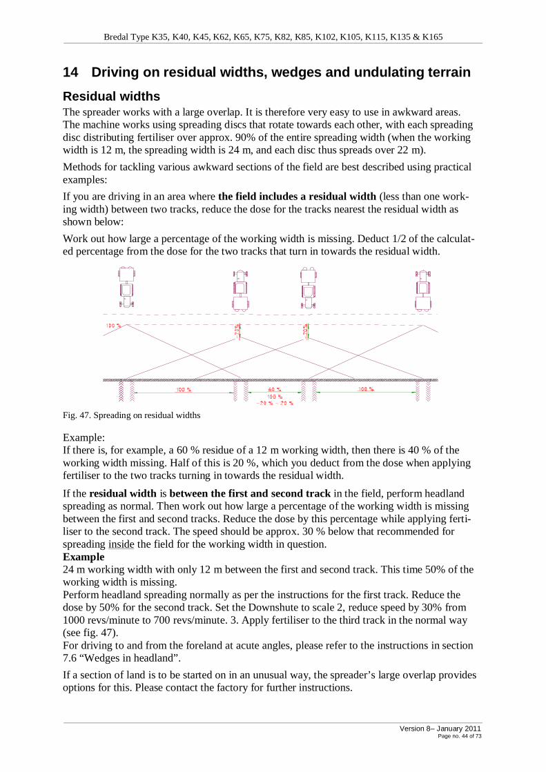
14 Driving on residual widths, wedges and undulating terrain
Residual widths The spreader works with a large overlap. It is therefore very easy to use in awkward areas. The machine works using spreading discs that rotate towards each other, with each spreading disc distributing fertiliser over approx. 90% of the entire spreading width (when the working width is 12 m, the spreading width is 24 m, and each disc thus spreads over 22 m).
Methods for tackling various awkward sections of the field are best described using practical examples:
If you are driving in an area where the field includes a residual width (less than one work-ing width) between two tracks, reduce the dose for the tracks nearest the residual width as shown below:
Work out how large a percentage of the working width is missing. Deduct 1/2 of the calculat-ed percentage from the dose for the two tracks that turn in towards the residual width.
Fig. 47. Spreading on residual widths
Example: If there is, for example, a 60 % residue of a 12 m working width, then there is 40 % of the working width missing. Half of this is 20 %, which you deduct from the dose when applying fertiliser to the two tracks turning in towards the residual width.
If the residual width is between the first and second track in the field, perform headland spreading as normal. Then work out how large a percentage of the working width is missing between the first and second tracks. Reduce the dose by this percentage while applying ferti-liser to the second track. The speed should be approx. 30 % below that recommended for spreading inside the field for the working width in question. Example 24 m working width with only 12 m between the first and second track. This time 50% of the working width is missing. Perform headland spreading normally as per the instructions for the first track. Reduce the dose by 50% for the second track. Set the Downshute to scale 2, reduce speed by 30% from 1000 revs/minute to 700 revs/minute. 3. Apply fertiliser to the third track in the normal way (see fig. 47). For driving to and from the foreland at acute angles, please refer to the instructions in section 7.6 “Wedges in headland”.
If a section of land is to be started on in an unusual way, the spreader’s large overlap provides options for this. Please contact the factory for further instructions.
Bredal Type K35, K40, K45, K62, K65, K75, K82, K85, K102, K105, K115, K135 & K165
Version 8– January 2011 Page no. 45 of 73
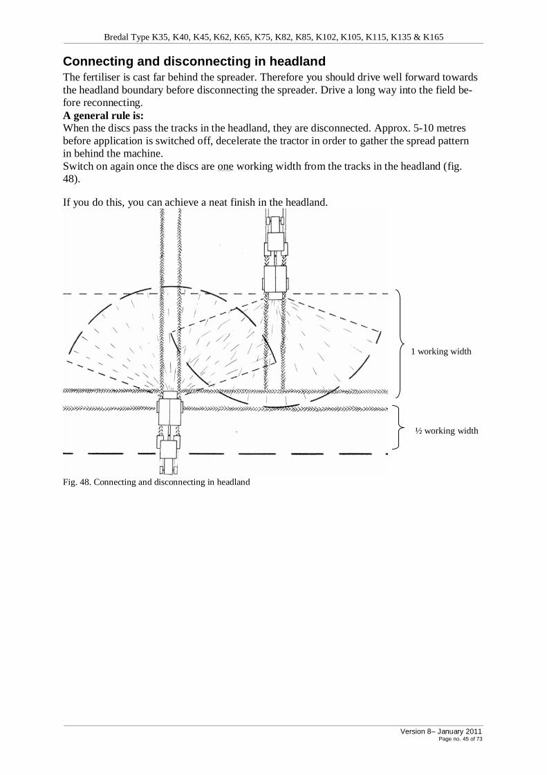
Connecting and disconnecting in headland The fertiliser is cast far behind the spreader. Therefore you should drive well forward towards the headland boundary before disconnecting the spreader. Drive a long way into the field be-fore reconnecting. A general rule is: When the discs pass the tracks in the headland, they are disconnected. Approx. 5-10 metres before application is switched off, decelerate the tractor in order to gather the spread pattern in behind the machine. Switch on again once the discs are one working width from the tracks in the headland (fig. 48).
If you do this, you can achieve a neat finish in the headland.
1 working width
½ working width
Fig. 48. Connecting and disconnecting in headland
Bredal Type K35, K40, K45, K62, K65, K75, K82, K85, K102, K105, K115, K135 & K165
Version 8– January 2011 Page no. 46 of 73
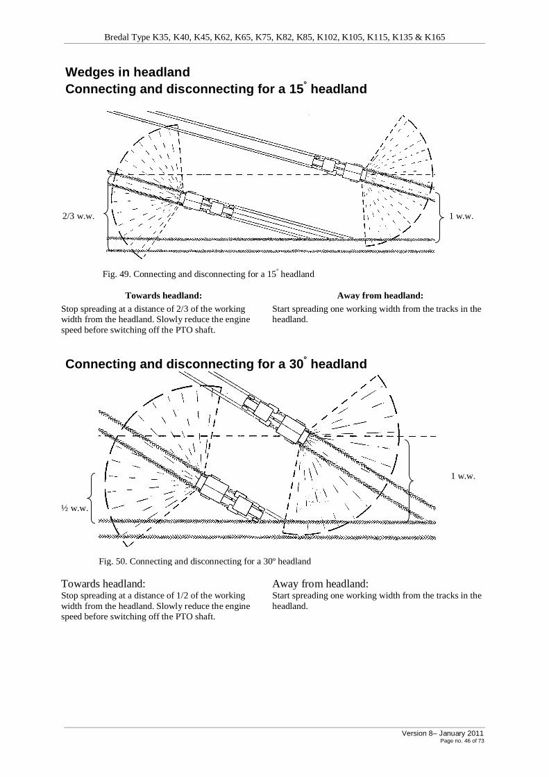
Wedges in headland Connecting and disconnecting for a 15° headland
2/3 w.w. 1 w.w.
Fig. 49. Connecting and disconnecting for a 15° headland
Towards headland: Away from headland:
Stop spreading at a distance of 2/3 of the working width from the headland. Slowly reduce the engine speed before switching off the PTO shaft.
Start spreading one working width from the tracks in the headland.
Connecting and disconnecting for a 30° headland
1 w.w.
½ w.w.
Fig. 50. Connecting and disconnecting for a 30º headland
Towards headland: Away from headland: Stop spreading at a distance of 1/2 of the working width from the headland. Slowly reduce the engine speed before switching off the PTO shaft.
Start spreading one working width from the tracks in the headland.

Bredal Type K35, K40, K45, K62, K65, K75, K82, K85, K102, K105, K115, K135 & K165
Version 8– January 2011 Page no. 47 of 73
Connecting and disconnecting for a 60° headland
1. w.w.
1/3 w.w.
Fig. 51. Connecting and disconnecting for a 60º headland.
Towards headland: Away from headland: Stop spreading at a distance of 1/3 of the working width from the headland. Slowly reduce the engine speed before switching off the PTO shaft.
Start spreading one working width from the tracks in the headland.
Spreading in hilly terrain If the area where spreading is to be performed undulates a great deal, it is necessary to set the spreader to the highest possible belt speed and the lowest possible shutter opening. This is par-ticularly important when spreading easy flowing, fine-grained fertiliser.

Bredal Type K35, K40, K45, K62, K65, K75, K82, K85, K102, K105, K115, K135 & K165
Version 8– January 2011 Page no. 48 of 73
15 Spreading special fertiliser using 12-36 m discs Before you spread special fertiliser we recommend you carry out a spreading test.
Below are Bredal’s recommendations only.
Recommended settings for N34 Ammonium nitrate (N34): Ammonium nitrate must not be compared with normal quality fer-tiliser, as it often does not have the same grain size and strength. A grain strength of 1-2 kg is not uncommon, while quality fertiliser has a grain strength of 4-6 kg and sometimes more. Grain size is also often smaller than that of normal quality fertiliser.
An average grain size of approx. 2.2 mm is not uncommon. Normal quality fertiliser has an average grain size of approx. 3 mm or more.
These factors have a crucial impact on the spreadability of the fertiliser. BEDAL A/S has performed spreading experiments in a spreading hall using an ammonium nitrate with the properties listed above.
If a large-grain ammonium nitrate (N34) with good grain strength can be obtained, greater spreading reliability can be achieved.
General setting recommendations for N34 iThese recommendations are for guidance. As N34 is of fluctuating size, we recommend always carrying out a spreading test before starting spreading.
Use standard settings for spreading N34 If there is too much fertiliser behind the spreader, raise the Downshute setting 2-3 scale in-tervals from the standard setting. If the spreader produces a lot of dust, or if there is a lot of crushed fertiliser in the tracks, reduce the PTO shaft speed.
Pure potash As potash runs rather sluggishly over the dischargers, it may be useful to adjust the Downshute scale 2 or 2.5 scale intervals higher than the recommended setting.
The Downshute settings should be higher than the standard setting.
Working width Downshute scale 12-16 m 2 scale intervals higher 18-24 m 2.5 scale intervals higher
Max. 24 metres working width with pure potash
It is important to select the highest possible belt speed and lowest possible shutter opening, as this fertiliser flows so sluggishly there could otherwise be problems with the shutters not fill-ing with fertiliser. Increase the dosage by approx. 10 % in accordance with application guide-lines.
Ammonium sulphate
For ammonium sulphate as well as for potash it may be best to adjust the Downshute settings.
For ammonium sulphate the Downshute settings should be 3 scale intervals higher than the standard setting.
Max. 24 m working width with ammonium sulphate

Bredal Type K35, K40, K45, K62, K65, K75, K82, K85, K102, K105, K115, K135 & K165
Version 8– January 2011 Page no. 49 of 73
Urea This fertiliser is available in two versions: one prilled and one granulated. Often urea is less effective in terms of spreading, as it has 3 significant properties against it.
Urea is usually very fine-grained (prilled variety). The urea grains have a low grain strength.
Urea has a low litre weight. These properties mean that urea cannot be thrown as far as most other fertilisers. Acceptable results can be achieved, however, if the following guidelines are followed.
iAlways remember to carry out a spreading test.
Prilled urea 9-12 m working width: The PTO shaft speed can be increased to 650-700 revs/min, if the grain strength is a mini-mum of 1-1.5 kg.
15-18 m working width: It is possible to achieve acceptable spreading on medium working widths, but not with dou-ble overlaps. The Downshute scale setting should be 5 and speed (rpm) should be determined by means of a spreading test to suit the type of urea and the working width.
20-24 m working width: At 15-18m grain strength must be at least 2 kg.
The speed (rpm) that results in even spreading should be kept constant, as it corresponds to the working width that you are working with.
Working widths 18 - 24 m using prilled varieties will form a box-shaped spreading curve, so grain size has a huge impact on the right speed for the PTO shaft. A change in grain size can give rise to a huge change in the quantity spread between the tracks. Take frequent spreading samples to check.
Granulated urea Granulated urea has a coarser surface than prilled urea. It normally has an average grain size of 3-3.5 mm and a grain strength of 2-3 kg.
Use the spreader’s standard settings up to 24 m working width, though the PTO shaft speed must not exceed 800 revs/min. if grain strength is 2 kg or under.
Large working widths require large-grain materials. Higher speeds (rpm) require hard-grained materials.
Always carry out a spreading test with the type of urea to be spread.
*) The urea must comply with grain size requirements for the various working widths and the grain strength requirements for the various speeds (rpm) (sect. 11). Urea’s litre weight is lower than that of ordinary fertiliser. Generally speaking, granulated urea is heavier than the prilled variety. As grain size is important for achieving a large working width, it is important to assess this before purchasing the urea. Due to the fluctuating quality of urea, it is always important to carry out a spreading test before spreading urea. The general guidelines for adjusting the spreading pattern (sect. 12) also apply to urea.

Bredal Type K35, K40, K45, K62, K65, K75, K82, K85, K102, K105, K115, K135 & K165
Version 8– January 2011 Page no. 50 of 73
Other factors concerning urea When purchasing urea you should bear the following factors in mind, in addition to the in-creased spreading risks:
100% exploitation of the nitrogen in the urea can only be achieved if it is ploughed in.
The urea must be converted by 2 different strains of bacteria in the earth before the plants can make use of the nitrogen in the urea. From the point when one type of bacteria has released the nitrogen in the urea until the other one takes it over, the nitrogen in the urea is gaseous and can easily evaporate.
The ground temperature must be above 5 degrees for conversion to occur. If the ground tem-perature is above 8 degrees, conversion will occur so rapidly that there will be a considerable risk of evaporation.
Rain immediately after the urea has been spread is advantageous, as it reduces the risk of evaporation.
When you buy fertiliser, remember that every time you save the value of one drum of ferti-liser, the effects of poor spreading and inefficient usage can add up to several drums’ worth.
Other special fertilisers etc.: There are special fertilisers on the market for specific purposes.
Some have the appearance of fine salt or sugar, and a litre weight of 1 kg/litre or over. It is usually possible to apply these at a PTO shaft speed of 540 rpm and a working width of 6 m using Downshute setting G on 110 (standard 12 m setting). iOver the years a great deal of material concerning other types of fertiliser has been collect-ed. Please contact us if you will be applying an unfamiliar type of fertiliser.
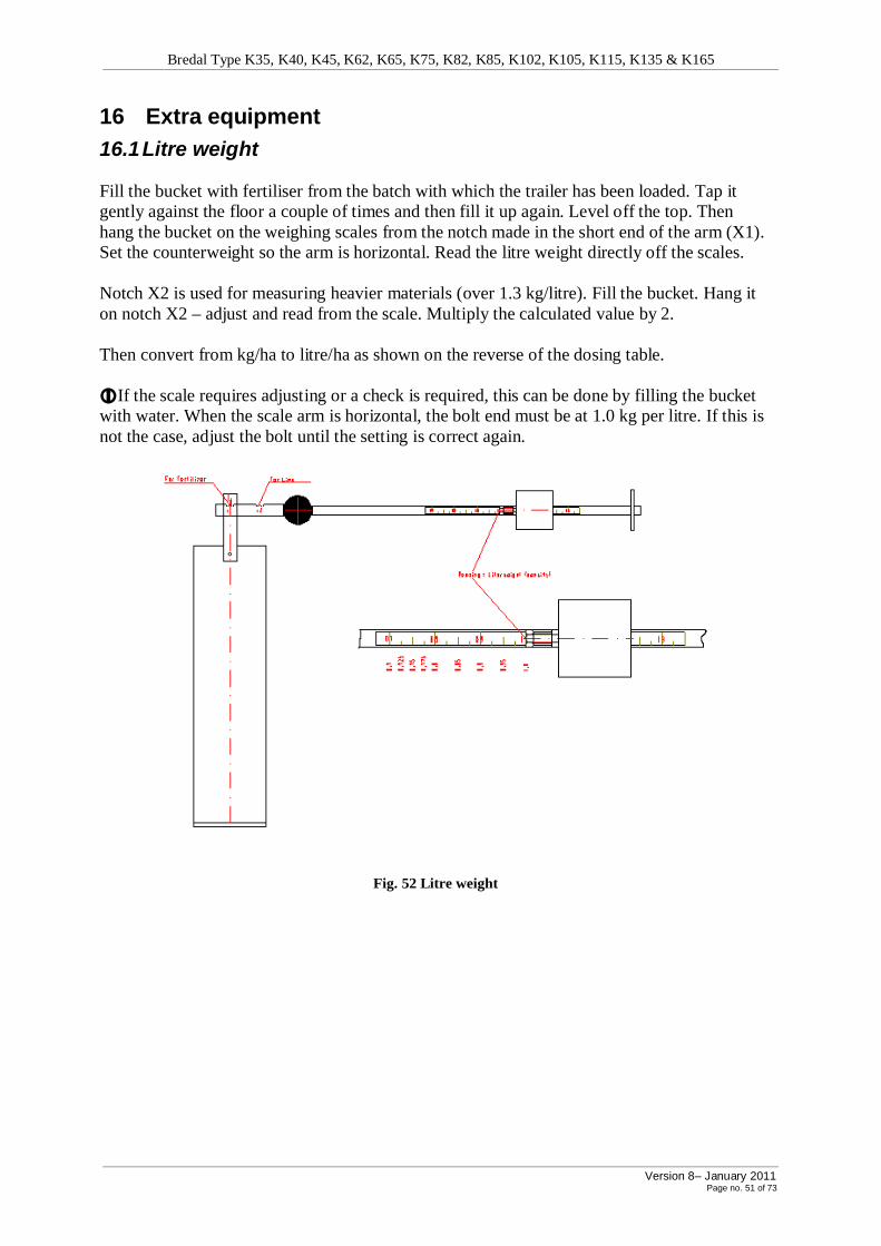
Bredal Type K35, K40, K45, K62, K65, K75, K82, K85, K102, K105, K115, K135 & K165
Version 8– January 2011 Page no. 51 of 73
16 Extra equipment
16.1 Litre weight
Fill the bucket with fertiliser from the batch with which the trailer has been loaded. Tap it gently against the floor a couple of times and then fill it up again. Level off the top. Then hang the bucket on the weighing scales from the notch made in the short end of the arm (X1). Set the counterweight so the arm is horizontal. Read the litre weight directly off the scales. Notch X2 is used for measuring heavier materials (over 1.3 kg/litre). Fill the bucket. Hang it on notch X2 – adjust and read from the scale. Multiply the calculated value by 2. Then convert from kg/ha to litre/ha as shown on the reverse of the dosing table. iIf the scale requires adjusting or a check is required, this can be done by filling the bucket with water. When the scale arm is horizontal, the bolt end must be at 1.0 kg per litre. If this is not the case, adjust the bolt until the setting is correct again.
Fig. 52 Litre weight

Bredal Type K35, K40, K45, K62, K65, K75, K82, K85, K102, K105, K115, K135 & K165
Version 8– January 2011 Page no. 52 of 73
16.2 Weight transfer
Fig. 53. Weight transfer system
1. Cylinder 2. Accumulator 3. Pressure control valve (set to 170 bar). 4. Compression face with manometer. 5. Attachment piece - tractor. 6. Adapted attachment piece for trailer. 7. Return hose, to go directly into sump.
The purpose of Bredal’s weight transfer is to avoid the fluctuations (jumps) that can arise when driving with different trailers. The problem is particularly pronounced for high-volume tyre vehicles. The extra load on tractor and trailer as a result of this jump can be avoided by means of this relief cylinder.
BREDAL has therefore designed this weight transfer for the largest of our lime spreaders, but at the same time the design is such that the system can also be used on other trailers, such as slurry tankers, earth trailers etc. The relief cylinder, accumulator and pressure control valve are in one unit and are intended to follow the tractor, so that the system can be used for sever-al different trailers.
BREDAL supplies a bracket for fixing the cylinder to the trailer. The actual fitting of this cyl-inder bracket is to be undertaken by the user.
Fig. 54. Mounting the weight transfer
The pressure control valve is adjusted to 170 bar, which corresponds to approx. 4.8 tons pressure. The pressure control valve is adjustable, enabling individual adjustment of maximum pressure. Normal working pressure is between 80 – 120 bar.
Important: i For the relief cylinder to function as intended, there must be a minimum pressure of 120 bars (preferably
more). Return hose should lead directly to the sump (It is essential that there be no counterpressure in the return hose). The accumulator has a pneumatic pressure of 55 bar.
Minimum installation di-mensions when tractor and tools are horizontal.
Piston stroke length is 450 mm. When the tractor and tools are horizontal, the cylinder must be discharged 225 mm.
Pipe is shortened and welded to muff

Bredal Type K35, K40, K45, K62, K65, K75, K82, K85, K102, K105, K115, K135 & K165
Version 8– January 2011 Page no. 53 of 73
16.3 Sand/salt equipment For spreading sand or salt or mixtures of these on roads, car parks etc, Maskinfabrikken Bredal A/S offers a sand/salt device.
This comprises a hydraulically-powered spreading disc, which is either fitted in the same holder as the double spreading discs supplied as standard – or (at extra cost) can be supplied fitted in an extra holder).
Fig. 55 Sand/salt disc fitted on K45
The spreading width can be varied by alter-ing the speed (rpm) of the disc by means of the valve shown in the illustration.
The disc is hydraulically-powered, and it is therefore necessary to have a single-acting outlet with return to the tractor.
Fig. 56. Control valve
The equipment can perform spreading over both large and small areas.
By moving the fallout point on the disc, the lateral distribution of the material can be al-tered, so that spreading can occur over the whole road from the right-hand lane. Fig. 57. Sand/salt disc
16.4 Top dressing with SPC4500 reversed spreading system SPC4500 reversed spreading system is ideal for top dressing etc. For this, rubber-coated spreading discs and dischargers are used, with a spreading width of 6-10 m working width.
Fig. 58. K45 Turf Dresser
A
Material
6-10 m 300 - 450 Sand / grit 20 i Remember that this device is not intended for spreading artificial fertiliser.

Bredal Type K35, K40, K45, K62, K65, K75, K82, K85, K102, K105, K115, K135 & K165
Version 8– January 2011 Page no. 54 of 73
16.5 Conveyor Maskinfabrikken Bredal A/S offers a sand boom belt as extra equipment for its K-spreaders. The belt is easily fitted to the suspension in which the spreading setup is mounted (the spread-ing discs), and can be replaced very quickly.
1. The sand boom applies the material in a even flow. There are therefore countless appli-cation possibilities:
2. Laying district heating pipes, gas pipes, electrical cables, drain pipes, water pipes and other earth-laid connections.
3. Spreading base gravel as edge reinforcement along roads. 4. Laying topsoil in verges. 5. Spreading chips in planted areas. 6. Laying sand when laying out pavements. 7. Depositing material in existing constructions (the nozzle can be removed, allowing the
belt to throw the material several metres) 8. Many more possibilities.
Technical data: • Capacity per minute up to 1 m3. • Maximum length of transporter: 4.2 m. • Belt widt: 0.4 m. • Turning angle to each side: 70 degrees (For
K-spreaders supplied with KB2 the belt CANNOT swing over to the left side).
• Belt speed (target): 100 m/minute (this de-pends on the amount of oil in the tractor)
Fig. 60. Sand transporter
• The belt comes as standard with a manual-ly-operated telescopic swinging rod. (A hy-draulic swinging cylinder can be supplied as an extra, so that the material down in Downshutes etc. can be controlled from the tractor).
• The belt is supported by 2 rows of bearing rollers set in a V-shape. 2 conical rollers are fitted for belt control. On the upper side, the belt is equipped with V-shaped carriers. The finisher is suspended from 4 bolts and a steel cable.
• Dismantling is extremely simple. The sys-tem can be used immediately together with a Bredal K-Spreader MED for motor-powered application, and using a hydraulic motor on a trailer for vehicle-operated ap-plication.

Bredal Type K35, K40, K45, K62, K65, K75, K82, K85, K102, K105, K115, K135 & K165
Version 8– January 2011 Page no. 55 of 73
16.6 Late fertilising
A late fertilising device is available for all Bredal K-type spreaders (fig. 61). This is fitted to the headland device bolts, which are welded on to the protection pipe bearing arms near the spreading discs on both sides. The sides of the late fertilising device are adjusted forward towards the screen in front of the spreading discs.
With this device it is possible to perform spreading in tall crops, with plant sections as high as the upper edge of the spreading discs.
Use the settings stated in the table below for late fertilising.
A
Scale B 12 m 0 350
15 m 0 450
16 m 0 450
18 m 1.5 600
20 m 1.5 600 120 24 m 2 700
28 m 3 800
30 m 4.5 850
32 m 5 850
36 m 6 850
iIt is extremely important that the late fertilising device is fitted horizontally on the spreader, otherwise the spreading will be skewed laterally.
iThe quality of fertiliser must meet the requirements set in section 11.
iPlease note that the late fertilising device lifts the fertiliser, so the spreading will be more susceptible to the wind than normal. The device should therefore never be used in strong winds.
When spreading prilled fertiliser, 2 scale intervals should be added to the Downshute values stated in the ta-ble.
For headland spreading, use the headland device as normal, but with the settings stated below.
Headland spreading
Fig. 61. Late fertilising device fitted to type B8
A 12 m 350 15 m 400 16 m 400 18 m 540 20 m 600 24 m 700 28 m 800 30 m 900 32 m 1000
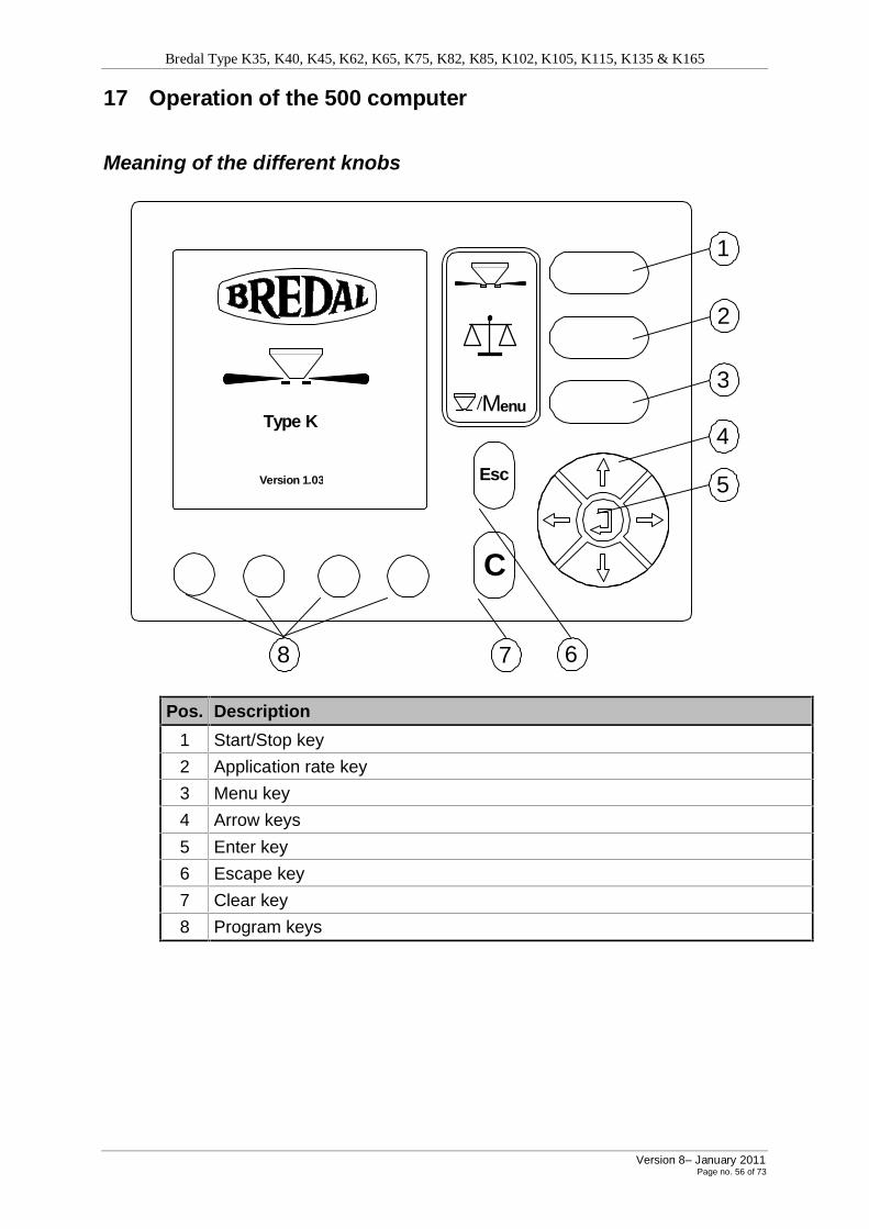
Bredal Type K35, K40, K45, K62, K65, K75, K82, K85, K102, K105, K115, K135 & K165
Version 8– January 2011 Page no. 56 of 73
17 Operation of the 500 computer
Meaning of the different knobs
C
Esc
Menu
Version 1.03
Type K 4
2
3
1
5
6 7 8
Pos. Description
1 Start/Stop key
2 Application rate key
3 Menu key
4 Arrow keys
5 Enter key
6 Escape key
7 Clear key
8 Program keys

Bredal Type K35, K40, K45, K62, K65, K75, K82, K85, K102, K105, K115, K135 & K165
Version 8– January 2011 Page no. 57 of 73
START/STOP KEY (1)
Key Description
Press this key to start or stop the spreader. If the spreader is oper-ating, this symbol is shown on the screen.
APLICATION RATE KEY (2)
Key Description
Press this key to calculate the Kg/ha based on the actual quantity remaining and the area which has been worked. This function can only be used when stationary, as it is very important for the calcula-tion that the weighing system is not in motion.
MENU KEY (3)
Key Description
Menu
Press the MENU key to change between the operation screen and the main menu. The key has a “toggle” function. If the operation screen is on display when the key is pressed, the main menu will be displayed. If this key is pressed while entering data, the display will change to the operation screen.
ARROW KEYS (4)
Key Description
The arrow keys are used to select and change settings.
When entering data, the arrow keys are used to select and set the digits which you wish to change. Each digit can be set to a value between 0-9 using the UP and DOWN arrows. Use the LEFT and RIGHT arrows to choose the digit to be changed.
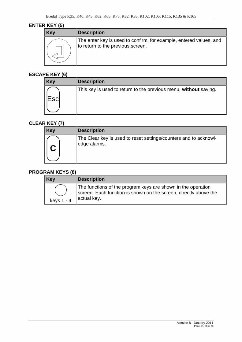
Bredal Type K35, K40, K45, K62, K65, K75, K82, K85, K102, K105, K115, K135 & K165
Version 8– January 2011 Page no. 58 of 73
ENTER KEY (5)
Key Description
The enter key is used to confirm, for example, entered values, and to return to the previous screen.
ESCAPE KEY (6)
Key Description
Esc
This key is used to return to the previous menu, without saving.
CLEAR KEY (7)
Key Description
C
The Clear key is used to reset settings/counters and to acknowl-edge alarms.
PROGRAM KEYS (8)
Key Description
keys 1 - 4
The functions of the program keys are shown in the operation screen. Each function is shown on the screen, directly above the actual key.
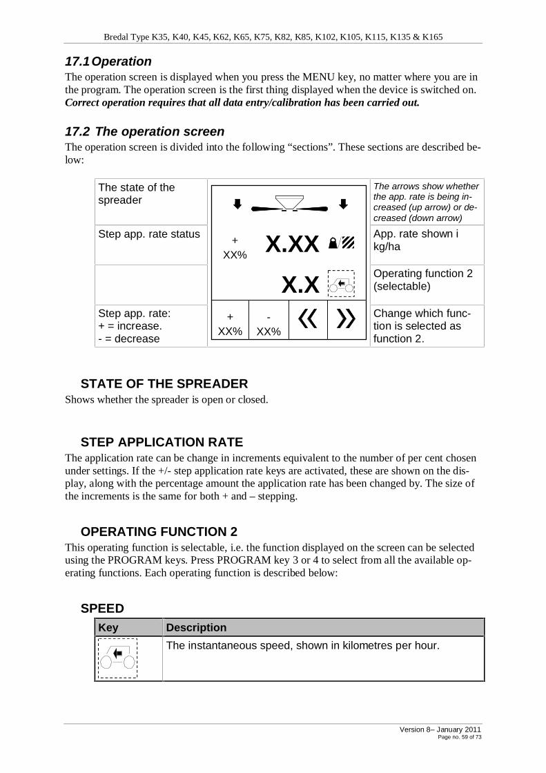
Bredal Type K35, K40, K45, K62, K65, K75, K82, K85, K102, K105, K115, K135 & K165
Version 8– January 2011 Page no. 59 of 73
17.1 Operation The operation screen is displayed when you press the MENU key, no matter where you are in the program. The operation screen is the first thing displayed when the device is switched on. Correct operation requires that all data entry/calibration has been carried out.
17.2 The operation screen The operation screen is divided into the following “sections”. These sections are described be-low:
The state of the spreader
+ XX%
X.XX
X.X
+ XX%
- XX%
The arrows show whether the app. rate is being in-creased (up arrow) or de-creased (down arrow)
Step app. rate status App. rate shown i kg/ha
Operating function 2 (selectable)
Step app. rate: + = increase. - = decrease
Change which func-tion is selected as function 2.
STATE OF THE SPREADER Shows whether the spreader is open or closed.
STEP APPLICATION RATE The application rate can be change in increments equivalent to the number of per cent chosen under settings. If the +/- step application rate keys are activated, these are shown on the dis-play, along with the percentage amount the application rate has been changed by. The size of the increments is the same for both + and – stepping.
OPERATING FUNCTION 2 This operating function is selectable, i.e. the function displayed on the screen can be selected using the PROGRAM keys. Press PROGRAM key 3 or 4 to select from all the available op-erating functions. Each operating function is described below:
SPEED
Key Description
The instantaneous speed, shown in kilometres per hour.
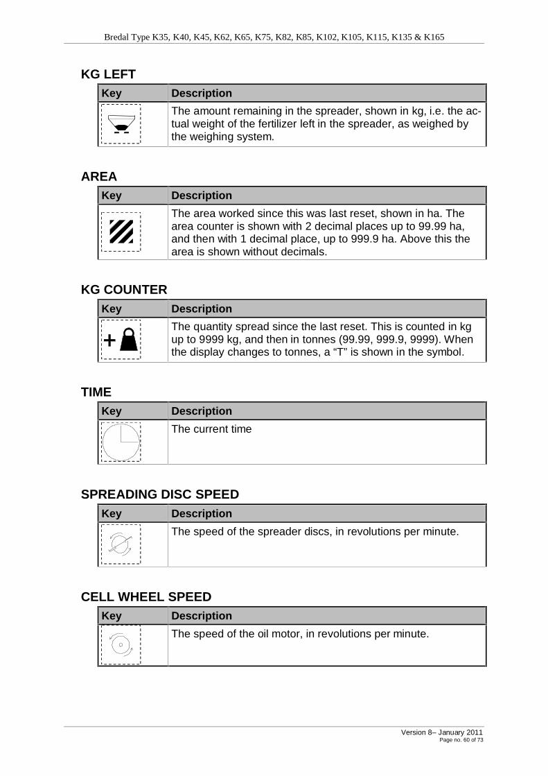
Bredal Type K35, K40, K45, K62, K65, K75, K82, K85, K102, K105, K115, K135 & K165
Version 8– January 2011 Page no. 60 of 73
KG LEFT
Key Description
The amount remaining in the spreader, shown in kg, i.e. the ac-tual weight of the fertilizer left in the spreader, as weighed by the weighing system.
AREA
Key Description
The area worked since this was last reset, shown in ha. The area counter is shown with 2 decimal places up to 99.99 ha, and then with 1 decimal place, up to 999.9 ha. Above this the area is shown without decimals.
KG COUNTER
Key Description
The quantity spread since the last reset. This is counted in kg up to 9999 kg, and then in tonnes (99.99, 999.9, 9999). When the display changes to tonnes, a “T” is shown in the symbol.
TIME
Key Description
The current time
SPREADING DISC SPEED
Key Description
The speed of the spreader discs, in revolutions per minute.
CELL WHEEL SPEED
Key Description
The speed of the oil motor, in revolutions per minute.

Bredal Type K35, K40, K45, K62, K65, K75, K82, K85, K102, K105, K115, K135 & K165
Version 8– January 2011 Page no. 61 of 73
KG/HOUR
Key Description
The amount being spread, shown in kg/min.
CALCULATION OF THE AVERAGE APP. RATE Press the APP. RATE key to calculate the average application rate for the amount of material spread since the last calculation. The average app. rate is calculated based on the quantity re-maining, either as an entered amount, if the system is not equipped with weighing cells, or the weighed amount remaining if it is. The average app. rate is calculated as follows:
CALCULATION WITH WEIGHING CELLS
Step/Key Description
1
Press the APP. RATE key, and this screen will be displayed:
Calculated XXXX
Weighed XXX
Actual flow factor New flow factor
X.XX
App. Rate Kg/ha
2
Press the “Fill” PROGRAM key and the calculation is reset.
This is done during refilling, or if the flow factor has been changed.
3. Spread an appropriate amount (depends on the desired app. rate), e.g. 600 kg.
3
Press the “Weigh” PROGRAM key to calculate the average app. rate, and a suggested new flow factor will be displayed.
4
If the new flow factor is acceptable:
Press the “Save” PROGRAM key, and the new flow factor will be saved. The contents of the spreader will automatically be weighed, and you can continue spreading.
5. If the new flow factor is not acceptable:

Bredal Type K35, K40, K45, K62, K65, K75, K82, K85, K102, K105, K115, K135 & K165
Version 8– January 2011 Page no. 62 of 73
Menu Press the MENU key and continue spreading until you have spread a greater amount.
CALCULATION WITHOUT WEIGHING CELLS
Step/Key Description
1
Press the APP. RATE key, and this screen will be displayed:
Calculated XXXX
Weighing XXX
Actual flow factor X.XX
New flow factor X.XX
App. Rate Kg/ha
2
Press the “Fill” PROGRAM key and enter the amount filled.
Do this when refilling the spreader.
3
When you want to calculate the app. rate, press the “Weigh” PROGRAM key, and enter the current quantity which is left in the spreader.
4
A new flow factor will automatically be calculated when you press the “Save” PROGRAM key.

Bredal Type K35, K40, K45, K62, K65, K75, K82, K85, K102, K105, K115, K135 & K165
Version 8– January 2011 Page no. 63 of 73
17.3 App. Rate setting The “App. Rate setting” menu can be selected from the main menu by pressing the MENU key and using the UP and DOWN arrows to select “App. Rate setting”. Then press the EN-TER key. Based on the data entered, the maximum speed is calculated. Max km/h can be viewed in the info menu.
KG/HA Select “Kg/Ha” to enter the desired application rate in Kg/Ha.
WIDTH Select “Width (m)” to enter the spreader’s working width in metres.
SPECIFIC GRAVITY (Density) Select “Specific gravity” to enter the specific gravity (density) of the fertilizer.
STEP %
Select “Step %” to enter the size of the increments in which you wish to change the app. rate.
FLOW FACTOR Select “Flow Factor” to enter the flow factor, if this is known.
17.4 Emptying The spreader can be emptied, while stationary, as follows:’
Step/Key Description
1 Menu
Press the MENU key.
2 Move the cursor using the UP and DOWN arrows to select “Emptying”.
3 Press the ENTER key.
4
The spreader can now be emptied by pressing the START/STOP key.
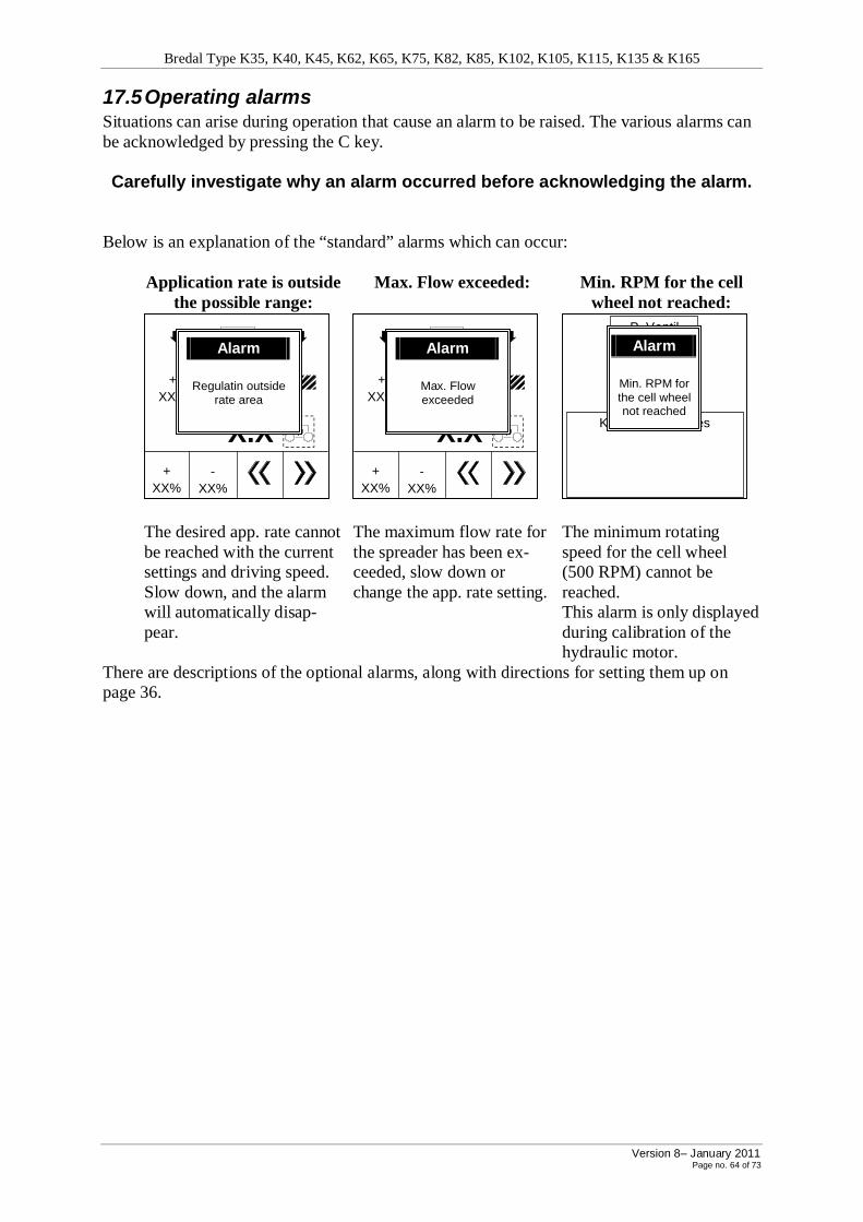
Bredal Type K35, K40, K45, K62, K65, K75, K82, K85, K102, K105, K115, K135 & K165
Version 8– January 2011 Page no. 64 of 73
17.5 Operating alarms Situations can arise during operation that cause an alarm to be raised. The various alarms can be acknowledged by pressing the C key. Carefully investigate why an alarm occurred before acknowledging the alarm.
Below is an explanation of the “standard” alarms which can occur:
Application rate is outside
the possible range: Max. Flow exceeded: Min. RPM for the cell
wheel not reached:
+ XX%
X.XX
X.X
+ XX%
- XX%
Alarm
Regulatin outside rate area
+ XX%
X.XX
X.X
+ XX%
- XX%
Alarm
Max. Flow exceeded
P. Ventil kalibrering
Kalibrering udføres
Alarm
Min. RPM for the cell wheel not reached
The desired app. rate cannot be reached with the current settings and driving speed. Slow down, and the alarm will automatically disap-pear.
The maximum flow rate for the spreader has been ex-ceeded, slow down or change the app. rate setting.
The minimum rotating speed for the cell wheel (500 RPM) cannot be reached. This alarm is only displayed during calibration of the hydraulic motor.
There are descriptions of the optional alarms, along with directions for setting them up on page 36.

Bredal Type K35, K40, K45, K62, K65, K75, K82, K85, K102, K105, K115, K135 & K165
Version 8– January 2011 Page no. 65 of 73
SETTINGS The “Settings” menu can be selected from the main menu by pressing the MENU key and us-ing the UP and DOWN arrows to select “Settings”. Then press the ENTER key.
17.6 Alarms Select alarm settings from the settings menu by selecting “Alarms” using the UP and DOWN arrows. Then press the ENTER key. The available alarms can be enabled and disabled using the following PROGRAM keys. Alarms which arise can be acknowledged using the C Key.
17.7
Key Description
Alarm on.
Alarm off.
KG LEFT ALARM You can turn the alarm ON/OFF, and set the minimum number of kg left in the spreader be-fore the alarm is to be raised.
DISC RPM ALARM You can turn the alarm ON/OFF, and set the minimum disc speed in RPM, below which the alarm should be raised.
17.8 Speed sensor The type of speed sensor, and the calibration factor can be set her. It is also possible to auto-matically calibrate the speed sensor. Select this menu from the settings menu by selecting “Speed sensor” using the UP and DOWN arrows. Then press the ENTER key.
Key Description
Press this key (program key 1) to select radar as the speed sensor (via the 7-pin DIN/ISO connector).
If the number of pulses per 100 m is known, this number can be entered directly.
Press this key (program key 2) to select a wheel sensor mounted on the tractor as the speed sensor (via the 7-pin DIN/ISO connector).
If the number of pulses per 100 m is known, this number can be entered directly.
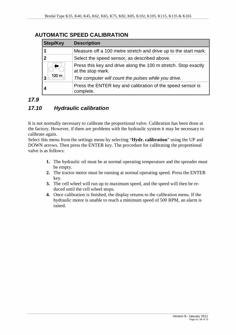
Bredal Type K35, K40, K45, K62, K65, K75, K82, K85, K102, K105, K115, K135 & K165
Version 8– January 2011 Page no. 66 of 73
AUTOMATIC SPEED CALIBRATION
Step/Key Description
1 Measure off a 100 metre stretch and drive up to the start mark.
2 Select the speed sensor, as described above.
3
Press this key and drive along the 100 m stretch. Stop exactly at the stop mark.
The computer will count the pulses while you drive.
4 Press the ENTER key and calibration of the speed sensor is complete.
17.9
17.10 Hydraulic calibration
It is not normally necessary to calibrate the proportional valve. Calibration has been done at the factory. However, if there are problems with the hydraulic system it may be necessary to calibrate again. Select this menu from the settings menu by selecting “Hydr. calibration” using the UP and DOWN arrows. Then press the ENTER key. The procedure for calibrating the proportional valve is as follows:
1. The hydraulic oil must be at normal operating temperature and the spreader must be empty.
2. The tractor motor must be running at normal operating speed. Press the ENTER key.
3. The cell wheel will run up to maximum speed, and the speed will then be re-duced until the cell wheel stops.
4. Once calibration is finished, the display returns to the calibration menu. If the hydraulic motor is unable to reach a minimum speed of 500 RPM, an alarm is raised.

Bredal Type K35, K40, K45, K62, K65, K75, K82, K85, K102, K105, K115, K135 & K165
Version 8– January 2011 Page no. 67 of 73
17.11 Application rate calibration Application rate calibration has normally been carried out at the factory and does not need to be done by the user. It will only be necessary to do it in special circumstances. Select this menu from the settings menu by selecting “App. Rate calibration” using the UP and DOWN arrows. Then press the ENTER key. For operational accuracy, the number of cm3 which is released per pulse needs to be set. If the quantity released per pulse is known in advance, it can be set directly. Otherwise the quantity released per pulse can be automatically calculated by calibrating the system as follows:
1. Select “New calibration” and press the RETURN key. 2. Enter the specific gravity (density) of the fertilizer (very important). 3. Press the ENTER key and the cell wheel is made ready (the cell wheel rotates
and is filled with fertilizer). 4. Empty the spill tray. 5. Press the START/STOP key to start the calibration (the cell wheel will turn). 6. Once a sufficient quantity has been released, stop the cell wheel by pressing the
START/STOP key. 7. Weigh the quantity released and enter the weight. 8. Press the ENTER key and the app. rate calibration is complete.
17.12 Weighing The Weighing menu can be selected from the main menu by pressing the MENU key and us-ing the UP and DOWN arrows to select “Weighing”. Then press the ENTER key. To set whether or not the system is equipped with weighing cells, select “Weighing” (in the Weighing menu) and then press the ENTER key. Press the ENTER key to toggle between Weighing = ON and Weighing = OFF.
17.13 TARE
The spreader must be empty and the PTO shaft must not be turning when you tare the weighing system.
To tare (reset) the weighing system, select “Tare” from the weighing menu, and press the ENTER key twice. The weighing system will then be reset.
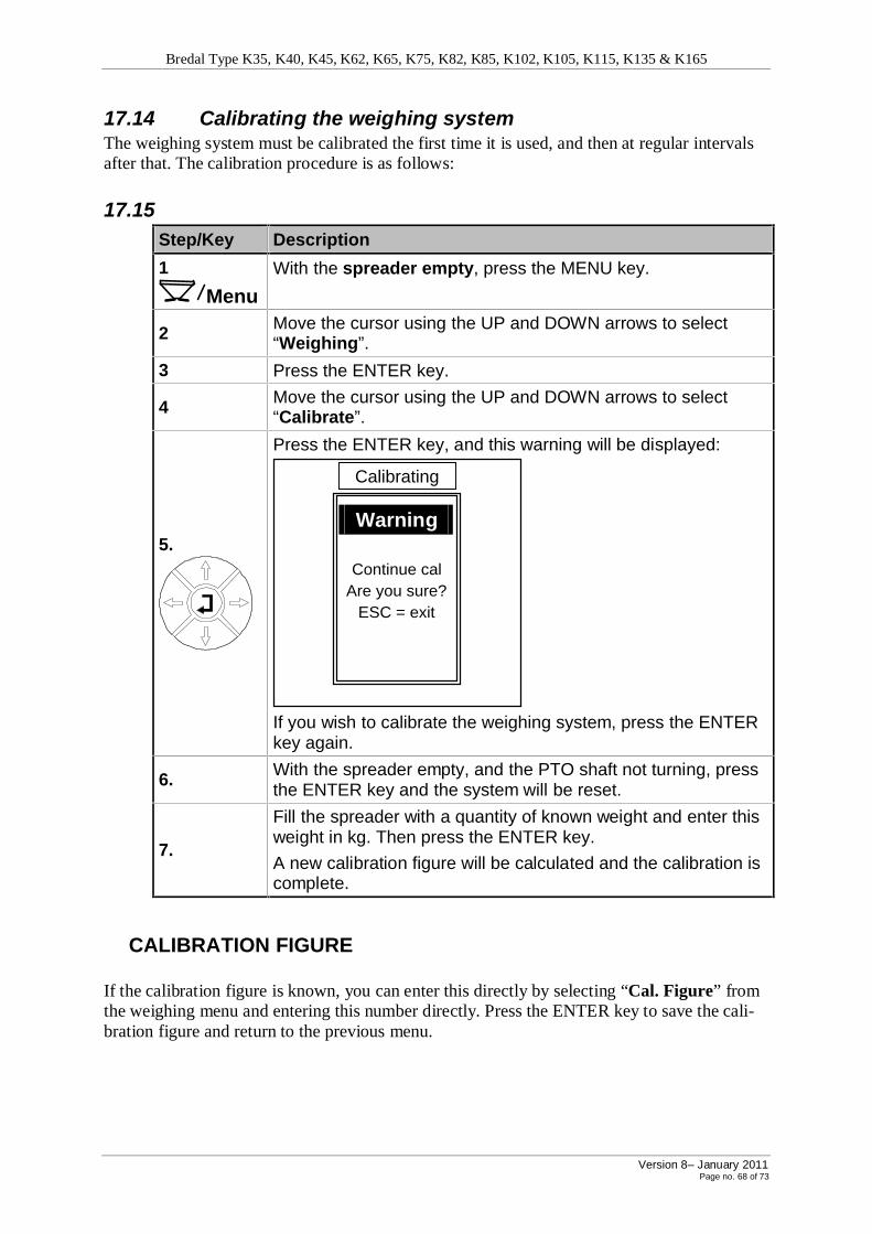
Bredal Type K35, K40, K45, K62, K65, K75, K82, K85, K102, K105, K115, K135 & K165
Version 8– January 2011 Page no. 68 of 73
17.14 Calibrating the weighing system The weighing system must be calibrated the first time it is used, and then at regular intervals after that. The calibration procedure is as follows:
17.15
Step/Key Description
1 Menu
With the spreader empty, press the MENU key.
2 Move the cursor using the UP and DOWN arrows to select “Weighing”.
3 Press the ENTER key.
4 Move the cursor using the UP and DOWN arrows to select “Calibrate”.
5.
Press the ENTER key, and this warning will be displayed:
Warning
Continue cal Are you sure?
ESC = exit
Calibrating
If you wish to calibrate the weighing system, press the ENTER key again.
6. With the spreader empty, and the PTO shaft not turning, press the ENTER key and the system will be reset.
7.
Fill the spreader with a quantity of known weight and enter this weight in kg. Then press the ENTER key.
A new calibration figure will be calculated and the calibration is complete.
CALIBRATION FIGURE If the calibration figure is known, you can enter this directly by selecting “Cal. Figure” from the weighing menu and entering this number directly. Press the ENTER key to save the cali-bration figure and return to the previous menu.

Bredal Type K35, K40, K45, K62, K65, K75, K82, K85, K102, K105, K115, K135 & K165
Version 8– January 2011 Page no. 69 of 73
17.16 Info The information menu displays an overview of the various settings, and can be accessed from the main menu (press the MENU key). Then use the UP and DOWN arrows to select “Info”, and press the ENTER key.
17.17
App. Rate (Kg/ha) XXX
Width (m) XX
Specific gravity X.XX
Step % XX
Flow factor X.XX
Max. Kmh XX.X
Info
17.18 Trip Counter It is possible to have up to ten different trip counters (jobs) in operation, which can be started and stopped, for example, when changing to another field. The trip counter menu can be accessed from the main menu (press the MENU key). Then use the UP and DOWN arrows to select “Trip counter”, and press the ENTER key. When you start a new job, the counters are reset. If you change to another job, and then change back again to the first job, the counters will continue counting from their previous values. Jobs can be reset individually.
TRIP COUNTERS FOR A JOB
New counter
Delete counter
Kg X
Area X.XX
Time X:XX
Trip counter
1/10
This window is displayed when you select the “Trip counter” menu. The individual counters are de-scribed below:

Bredal Type K35, K40, K45, K62, K65, K75, K82, K85, K102, K105, K115, K135 & K165
Version 8– January 2011 Page no. 70 of 73
Kg: The total number of kg spread since the job was started or last reset. Area: The accumulated area worked since the job was started or last reset. This area corresponds to the effective area, i.e., only the area which has been spread. Time: The total effective time spent since the job was started or last reset.
STARTING OR CONTINUING A JOB When you select the “Trip counter” menu, the last job you accessed is re-opened. If this is the very first job you are starting, job one will be opened.
Counter no 1
Counter no 2
Counter no 3
Counter no 4
Counter no 5
Counter no 6
Trip counter
To start or continue another job, press the “New counter” key. You can then select between jobs 1 – 10 by using the UP and DOWN ar-row keys to highlight the desired number. Then press the ENTER key.
To return to the operation screen, press the MENU key.
RESETTING A JOB If you want to reset the counters for a job, select the job as described above, and then select “Delete counter” and press the ENTER key.

Bredal Type K35, K40, K45, K62, K65, K75, K82, K85, K102, K105, K115, K135 & K165
Version 8– January 2011 Page no. 71 of 73
17.19 System The system menu can be accessed from the main menu (press the MENU key). Then use the UP and DOWN arrows to select “System”, and press the ENTER key.
CONTRAST/LIGHT
Key Description
Press this program key to make the display brighter.
Press this program key to make the display darker.
Press this program key to activate the auto light feature. The display light turns off, and turns on automatically when any key is pressed.
Use this key to turn the display light on and off.
LANGUAGE This option allows you to choose the working language for the LH Bredal 500 computer.
SPEED SIMULATE It is possible to simulate a speed, for example when troubleshooting or when you wish to spread independent of the driving speed. You can enter the desired simulated speed in km/h, with 1 decimal place. The speed simulation can be started and stopped using PROGRAM keys 1 & 2.

Bredal Type K35, K40, K45, K62, K65, K75, K82, K85, K102, K105, K115, K135 & K165
Version 8– January 2011 Page no. 72 of 73
17.20 Test
TEST INPUT Use the test input feature if, for example, you believe a sensor may be defective. For each input, there is a counter shown on the right side of the display which indicates the number of times that input has been activated (the counter resets automatically when you leave the “Test Input” menu, or if you press the C key). On the left side, the instantaneous status of the input is shown (Hi/Lo). You can page through the inputs by pressing the UP and DOWN arrows (2 pages in total). The input names displayed correspond to the following items:
Input Description
Wheel DIN/ISO
Speed signal from the wheel sensor installed on the tractor (via the 7-pin DIN/ISO connector in the tractor).
Radar DIN/ISO
Speed signal from the radar installed on the tractor (via the 7-pin DIN/ISO connector in the tractor).
RPM cell wheel
Signal from the RPM sensor mounted near the cell wheel.
Press the DOWN arrow key to see the next set of inputs:
RPM disc Signal from the RPM sensor mounted near the discs.
Weighing Signal from the weighing system.
Press the UP arrow key to see the first set of inputs:
TEST PROPORTIONAL. Valve In order to test the hydraulic motor’s proportional valve, you must specify a “duty cycle %”. Enter the desired duty cycle percentage, and then press the ENTER key.
TOTAL COUNTERS Under the system menu you will find the following total counters:
Kg: The total amount spread, in kg, since the last reset. Area: The total area spread since the last reset. Time: The accumulated time which the spreader has been working.
You can reset a counter by selecting it and then pressing the C key.
HYDRAULIC VALVE TYPE Here you can select which type of valve is installed on the spreader.

Bredal Type K35, K40, K45, K62, K65, K75, K82, K85, K102, K105, K115, K135 & K165
Version 8– January 2011 Page no. 73 of 73
18 Calibration of spread unit ENGLISH Checking scale setting on SPC spread units. To set in the right scale value by mounting or verifying the settings, it´s now possible by us-ing this new calibration finger.
Calibration finger Finger in position Scale value 120 The calibration finger has to touch the downshute plate and at the same time touch the spread disc and also touch the cone on top of the spread disc. When the calibration finger is in it´s right position the scale value must be 120. If not the scale needs to be adjusted by loosening the 2 screws on each arm for holding the spread unit.