k-line plus kp-32, kp-40 and kpe-40 installation ... - … · the kp-32/40 family of circuit...
TRANSCRIPT

IB 6.2.11.1-2C
Installation/Maintenance Instructions Low Voltage Power Circuit Breaker
K-Line Plus® Types KP-32, KPE-32, KP-40 and KPE-40
ABB

NOTE: This Instruction Book is provided solely for the convenience of the purchaser, and does not purport to cover all details or variations in equipment nor to provide for every possible contingency to be met in connection with installation, operation, or maintenance. Should further information be desired or should particular problems arise which are not covered sufficiently for the purchaser’s purposes, the matter should be referred to the nearest Sales Representative.
INTRODUCTION ....................................................... 3 RECEIVING AND STORAGE .................................... 3 BASIC HANDLING .................................................... 3 CIRCUIT BREAKER RATING ................................... 3 ESCUTCHEON OPERATING FEATURES ............... 3 Circuit Breaker Nameplate .................................... 4 Manual Charging Handle ....................................... 4 Manual Trip Button ................................................ 4 Circuit Breaker "OPEN" or "CLOSED" Indicator .... 4 Automatic Trip Indicator ......................................... 4 Automatic Trip Alarm Contacts .............................. 4 Automatic Trip Lockout Device .............................. 4 Padlocking Device ................................................. 4 Closing Spring Charge Indicator ............................ 4 Motor Disconnect Switch ....................................... 4 Electrical Close & Trip Push Buttons ..................... 4 Manual Close Lever ............................................... 8 Racking Mechanism .............................................. 8 CIRCUIT BREAKER INTERNAL COMPONENTS .... 8 Solid State Control Device (SSCD) ....................... 8 Shunt Trip .............................................................. 8 Close Coil .............................................................. 8 Closing Spring Charging Motor ............................. 8 Closing Spring Check Switch (CSCS) ................... 8 Auxiliary Switches .................................................. 8 Undervoltage Trip Device ...................................... 9 MPSC-2000 SOLID STATE TRIP SYSTEM .............. 9 Selecting Trip Settings ......................................... 10 OPERATING SEQUENCE FOR EO BREAKERS ... 10 CLOSING SPRING OPERATION ........................... 11 INSTALLATION, INITIAL TESTING & REMOVAL .. 11 Installation ........................................................... 11 Checking Breaker Operation in “TEST” ............... 11 Checking Breaker Operation in “CONNECTED” . 11 Manual Closing Operation ................................... 12 Circuit Breaker Removal ...................................... 12 MAINTENANCE AND ADJUSTMENTS .................. 12 Periodic Maintenance Inspection ......................... 12 Arc Chutes ........................................................... 12
Insulation Structure ..............................................13 MPSC-2000 Trip Device Removal & Installation ..13 Electrical Components (EO only) .........................13 Contact .................................................................13 Contact Pitting ......................................................13 Contact Pressure Check and Adjustment ............13 Manual Slow Close to Check Contact Pressure ..14 Operating Mechanism ..........................................14 Primary Trip Latch ............................................15 Tripper Bar Adjustment ....................................15 Primary Close Latch .........................................15 Shunt Trip Device .............................................15 FIELD TESTING THE MPSC-2000 TRIP SYSTEM 16 Instantaneous or Short Time Threshold Test .......16 Long Time Threshold Test ...................................16 Long Time Delay Test ..........................................17 Short Time Delay Tests ........................................17 Ground Trip Delay Tests ......................................17 LUBRICATION .........................................................17 DIELECTRIC TESTS ...............................................18 RENEWAL PARTS ..................................................19
Table of Contents
FIGURES Figure 1 - Typical Electrically Operated Breaker .......5 Figure 2 - Typical Composite Schematic (EO) ...........6 Figure 3 - Contact Pressure and Adjustment ...........13 Figure 4 - Shutter Detail ...........................................14 Figure 5 - Primary Trip Latch Adjustment ................14 Figure 6 - Tripper Bar Adjustment ............................14 Figure 7 - Primary Close Latch Adjustment .............15 Figure 8 - Shunt Trip Device Adjustment .................15
TABLES Table 1 - Secondary Disconnect Assignments ..........7 Table 2 - Electrical Characteristics of Devices ...........8 Table 3 - Undervoltage Trip Device Operating Data ..9 Table 4 - MPSC-2000 Typical Delay Bands ............16

IB 6.2.11.1-2C Page 3 ABB
INTRODUCTION The KP-32/40 family of circuit breakers are low voltage AC power circuit breakers featuring draw-out construction and the MPSC-2000 microprocessor-based trip system with RMS sensing. These circuit breakers can be furnished with either electrically operated (EO) or manually operated (MO) mechanisms. On EO models, various control power combinations are available, and numerous options are available for both mechanism styles. These instructions apply to the ANSI-rated “KP” series (KP-32 and KP-40), and the extended-rated “KPE” series (KPE-32 and KPE-40). An electrically operated, drawout type circuit breaker is shown in Figure 1, with a typical schematic diagram shown in Figure 2. These instructions should be read thoroughly before handling, installing and/or operating the circuit breaker. RECEIVING AND STORAGE Immediately upon receipt of the circuit breakers, examine the cartons to determine if any damage or loss was sustained during transit. If injury or rough handling is evident, file a damage claim at once with the carrier and promptly notify the nearest District Office. The Company is not responsible for damage of goods after delivery to the carrier. However, the Company will lend assistance if notified of claims. Unpack the circuit breakers as soon as possible after receipt. If unpacking is delayed, difficulty may be experienced in making a claim for damages not evident upon receipt. Use care in unpacking in order to avoid damaging any of the circuit breaker parts. Check the contents of each carton against the packing list before discarding any packing material. If any shortage of material is discovered, promptly notify the nearest District Office. Information specifying the purchase order number, carton number and part numbers of the damaged or missing parts should accompany the claim. Circuit breakers should be installed in their permanent location as soon as possible (see Basic Handling below). If the breakers are not to be placed in service for some time, it is advisable to provide adequate means of protection. This may he done by keeping the breaker in its original carton, covering with waterproof paper and sealing to prevent infiltration of dirt. Where conditions of high humidity prevail, the use of heaters is recommended.
BASIC HANDLING Once the circuit breaker has been unbolted and removed from its shipping carton, it should be turned to the upright position and placed on a flat surface to avoid damage to breaker parts. For safety, all handling in this position should utilize the lifting yoke (9) shown in Figure 1. CIRCUIT BREAKER RATING The circuit breaker continuous current rating (in hundreds of amps) is given by the number which follows the type designation (e.g., KP-40 = 4000A). If required, the breakers can be fitted with lower ampere current sensors and trip systems, which provide tripping below the actual continuous current rating of the frame size. Exceeding the continuous current rating of the circuit breaker for extended periods may raise the temperature of the circuit breaker beyond the limits set forth in ANSI C37.13 thus affecting the life of the circuit breaker insulating materials. The MPSC-2000 trip system has a tolerance band on long time of minus zero, plus ten percent (-0, +10%) which will allow the circuit breaker to carry its rated continuous current but will provide tripping above that value. Additionally, root mean square (RMS) current calculation on the long time trip element provides tripping based on the true heating value of the current passing through the circuit breaker. ESCUTCHEON OPERATlNG FEATURES Manually and electrically operated circuit breakers are provided with an extended escutcheon face plate. This escutcheon provides a central area for the controls which are mounted directly on the circuit breaker. Figure 1 shows the controls and other features provided on a typical electrically operated circuit breaker. The controls for manually operated circuit breakers are the same, except that the manual charging handle (16) is standard and the charge motor and its cut-off switch are not provided. A self-aligning plate, immediately behind the escutcheon face plate, is used to exclude dust from the circuit breaker compartment. The escutcheon face will protrude through the front door of the compartment when the circuit breaker is in the “TEST” and "DISCONNECTED" positions. In these positions, the dustplate still functions to exclude dust.

IB 6.2.11.1-2C Page 4 ABB
Circuit Breaker Nameplates (Figure 1, Item 4). The circuit breaker nameplates contain information regarding the manufacturer's name and address, type of circuit breaker design, serial number of circuit breaker, continuous current rating of frame size, short circuit current rating at rated voltages, frequency, short time current, and breaker control voltages. Manual Charging Handle (Figure 1, Item 16). The manual charging handle is a T-shaped lever used to charge the closing springs by pumping approximately ten times. Manual Trip Button (Figure 1, Item 10). The manual trip button, when pushed, trips the circuit breaker to "OPEN." Circuit Breaker "OPEN" or "CLOSED" Indicator (Figure 1, Item 2). This indicator shows the physical position of the circuit breaker contacts. Automatic Trip Indicator (Figure 1, Item 15). (Not including undervoltage, alarm switch, or lockout). The automatic trip indicator is provided as standard equipment on the K-Line Plus circuit breakers and is used to indicate the operation of the overcurrent trip device. This device is an indicator only and does not prevent the circuit breaker from reclosing. Upon an overcurrent trip operation, the indicator protrudes from the front plate approximately 1/2 inch. The automatic trip indicator should be reset after each trip indication by pushing it back into its normal latch position. The operator should investigate the cause of tripping before resetting the automatic trip indicator and subsequently reclosing the circuit breaker after an outage which results in an operation of the indicator. Automatic Trip Alarm Contacts (optional - not shown). An alarm switch for remote electrical indication, which is optional, shows when automatic tripping has occurred. This is accomplished by adding a precision snap switch to the automatic trip indicator assembly. The automatic trip indicator actuates the roller on the alarm switch which in turn causes a normally open contact to close and a normally closed contact to open on overcurrent trip. The alarm contact is manually reset by pushing the trip indicator back into its normal position. Automatic Trip Lockout (optional - not shown). An additional optional device may be added to the automatic trip indicator assembly device which serves to mechanically prevent reclosing the circuit breaker after an automatic trip operation. When the trip indicator is pushed in, the circuit breaker mechanism
can then be operated to close the circuit breaker contacts. Padlocking Device (Figure 1, Item 13). All K-Line Plus circuit breakers are equipped with means of padlocking the circuit breaker mechanism in a trip-tree position. This is accomplished by the use of a locking plate to maintain the manual trip button in a tripping direction when the locking plate is held forward by one or more padlocks. To obtain the condition for padlocking the circuit breaker in the open position, the manual trip button is pushed inward. Then the padlock plate is pulled out and the padlock inserted into the vertical slot. In this position, the mechanism is maintained trip free and the contacts cannot be moved to the closed position. The padlocking device is also associated with the drawout interlocking mechanism so that the circuit breaker cannot be moved from any of its three basic drawout positions of "CONNECTED", “TEST” or "DISCONNECTED" with the padlocking in effect. Closing Spring Charge Indicator (Figure 1, Item 6). Under normal operating conditions, the closing springs of an electrically operated breaker are automatically charged after each tripping operation. However, there are occasions when the springs will be in a discharged state. Therefore, it is desirable that means be available to indicate the condition of the closing springs. This is accomplished by a visual indicator seen through an aperture in the escutcheon plate. The indicator is marked "CHARGED" and "UNCHARGED." Motor Disconnect Switch (Figure 1, Item 14). The motor disconnect switch (EO breakers only) is a double pole, single-throw toggle type switch connected in series with the charging motor circuit and is used to disconnect the motor from the voltage source. This switch is used: (a) when it is desirable to prevent automatic recharging of the closing springs just prior to taking the circuit breaker out of service for maintenance, and (b) for control wiring dielectric test. The motor must be disconnected for the control wiring dielectric test and subsequently tested at the appropriate voltage. Electrical Close and Trip Push Buttons (Optional, Figure 1, Item 20). The electrical close and trip push buttons are used to electrically operate the circuit breaker from the escutcheon. These contacts are connected in series with their respective latch release coils. Energizing the close latch release coil allows the charged springs to close the circuit breaker, while energizing the trip latch release coil allows the breaker to open.
(Continued on page 8)

IB 6.2.11.1-2C Page 5 ABB
1. Arc Chute 2. “OPEN” or “CLOSED” Indicator 3. MPSC-2000 Trip Device 4. Nameplates 5. Escutcheon Assembly with Self-
Aligning Dust Cover 6. Spring Charge Indicator 7. Wheels 8. Racking Handle (Optional) 9. Lifting Rig (Optional) 10. Manual Trip Button
11. Drawout Lever 12. Manual Close Lever 13. Padlock Hasp 14. Motor Disconnect Switch (EO only) 15. Automatic Trip Indicator 16. Manual Charging Handle (Optional) 17. Position Indicator Label 18. Spring Charging Motor (EO only) 19. Racking Cam Rollers 20. Electrical Trip & Close Buttons
(Optional - Not Shown)
Figure 1 - Typical Electrically Operated K-Line Plus Circuit Breaker
1
19
3
4
5 18
17 7
9
16
2
8 11
13
6
10
15 14 20
12
IB 6.2.11.1-2C Page 6 ABB
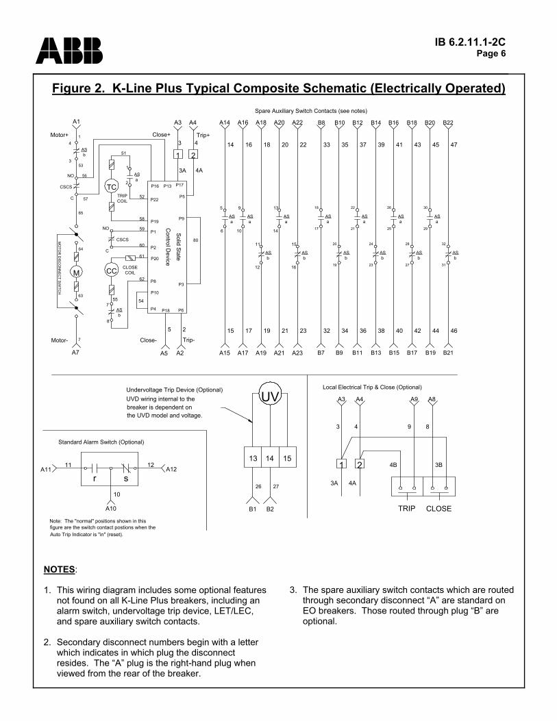
NOTES: 1. This wiring diagram includes some optional features
not found on all K-Line Plus breakers, including an alarm switch, undervoltage trip device, LET/LEC, and spare auxiliary switch contacts.
2. Secondary disconnect numbers begin with a letter
which indicates in which plug the disconnect resides. The “A” plug is the right-hand plug when viewed from the rear of the breaker.
3. The spare auxiliary switch contacts which are routed
through secondary disconnect “A” are standard on EO breakers. Those routed through plug “B” are optional.
Figure 2. K-Line Plus Typical Composite Schematic (Electrically Operated)
60
58
52
59
Close+
55 54
62
Close-
MO
TOR
DISC
ON
NEC
T SWITC
H
Motor-
A7
M CC
8
COIL
61
CLOSE
7
COILTRIP
bAS
Motor+
A1
bAS
4
3
TC
1
51
2a
AS
Trip-
Control D
evice
5
P18
A5
P4
P20
P8
2
P6
A2
P2
P19
P22
P1
P10
Solid State
3A
1
3
A3
P17
4Trip+
A4
2
P5
4A
1
7
P9
P3
80
191715
A14 A18A16
2321
A22A20
14 1816 20 22
A15 A21A19A17 A23
5
6
ASa
10
AS
9
a
12
AS
11
b
14
AS
13
a
16
AS
15
b
53
65
CSCS
CSCS
64
63
56
57
NO
C
C
NO
B21
32
31
B22
B13B9 B11B7
3432 36
B15 B17 B19
38 40 42 44
19
17
18
aAS
20
21
23
bAS
22
ASa
24
3533 37
28
27
25
ASb
26
aAS
29
30
ASb
ASa
39 41 43 45
B14B10B8 B12 B18B16 B20
46
bAS
47
Standard Alarm Switch (Optional)
15
B1 B2
the UVD model and voltage.breaker is dependent onUVD wiring internal to the
26
13
27
14
UVUndervoltage Trip Device (Optional) Local Electrical Trip & Close (Optional)
Spare Auxiliary Switch Contacts (see notes)
A12
A10
rA11
11
s10
12 4B
4A3A
1 2
4
A4
3
A3
TRIP CLOSE
3B
9
A9
8
A8
Note: The "normal" positions shown in thisfigure are the switch contact postions when theAuto Trip Indicator is "in" (reset).
P16 P13

IB 6.2.11.1-2C Page 7 ABB
Table 1. K-Line Plus Secondary Disconnect Assignments
Pin Description Pin Description A1 Charge Motor + B1 Undervoltage Trip Device + A2 Shunt Trip - B2 Undervoltage Trip Device - A3 Close Coil + B3 (MPSC-2000 4WG or DESP) 6 A4 Shunt Trip + B4 (MPSC-2000 4WG or DESP) 6 A5 Close Coil - B5 (MPSC-2000 4WG or DESP) 6 A6 MPSC-2000 VIM B6 (MPSC-2000 4WG or DESP) 6 A7 Charge Motor - B7 Aux. Sw. "a" + A8 Local Elec. Close + B8 Aux. Sw. "a" - A9 Local Elec. Trip + B9 Aux. Sw. "b" + A10 Alarm Switch 4 B10 Aux. Sw. "b" - A11 Alarm Switch 4 B11 Aux. Sw. "a" + A12 Alarm Switch 4 B12 Aux. Sw. "a" - A13 Alarm Switch 4 B13 Aux. Sw. "b" + A14 Aux. Sw. "a" + B14 Aux. Sw. "b" - A15 Aux. Sw. "a" - B15 Aux. Sw. "a" + A16 Aux. Sw. "a" + B16 Aux. Sw. "a" - A17 Aux. Sw. "a" - B17 Aux. Sw. "b" + A18 Aux. Sw. "b" + B18 Aux. Sw. "b" - A19 Aux. Sw. "b" - B19 Aux. Sw. "a" + A20 Aux. Sw. "a" + B20 Aux. Sw. "a" - A21 Aux. Sw. "a" - B21 Aux. Sw. "b" + A22 Aux. Sw. "b" + B22 Aux. Sw. "b" - A23 Aux. Sw. "b" - B23 (Spare) 5 A24 (Spare) 5 B24 (Spare) 5 A25 (Not Used) B25 (Not Used)
supplied with the breaker for pin-out assignments. (6) The assignments for pins B3 - B6 will differ depending on whether the DESP option has been supplied. See
the MPSC-2000 schematic supplied with the breaker.
Notes: (1) These assignments are
provided for reference only, and may be changed due to special requirements. Some pins or plugs may not be present on all breaker configurations. See the breaker schematic wiring diagram(s) for details.
(2) Note the polarity of control
devices: “+” is the send and “-” is the return.
(3) The two terminals of each
Auxiliary Switch contact are connected to adjacent Secondary Disconnect pins. For example, pins A14 and A15 are connected to a single “a” contact. Also, the polarity signs are provided on these pins for consistency only; the Auxiliary Switch contacts are not polarity sensitive.
(4) The Alarm Switches can be
wired in two different ways. See the schematic supplied with the breaker for details on the pin-outs.
(5) The pins marked “(Spare)”
may be used in some b r e ak e r s f o r s p ec i a l c u s t o m e r w i r i n g requirements. Refer to the schematic wiring diagram

IB 6.2.11.1-2C Page 8 ABB
(Continued from page 4) Manual Close Lever (Figure 1, Item 12). The manual close lever is provided on all circuit breakers to provide a safe means of closing the breaker without control power. The lever is provided with a hole through which a lanyard should be attached for closing the breaker at a safe distance . Racking Mechanism. The racking mechanism is used to move the circuit breaker to any one of its three p o s i t i o n s : " C O NNE C T E D " , " T E S T ” , o r “DlSCONNECTED." All of these positions are attainable with the cubicle door closed or opened. The breaker can be closed only when the drawout lever (11, Figure 1) is up. When up, the racking crank (8, Figure 1) cannot be turned. The circuit breaker must be in the "OPEN" position before lever (11, Figure 1) can be pushed down. In order to move the circuit breaker from one position to another, the lever must be pushed down and the crank turned; once turning begins, the lever will stay down until another position is reached and the lever will snap up, preventing additional turning, until the lever is again pushed down. When the padlocking device is locked, the lever (11) is locked in the up postion preventing movement of the racking mechanism. There is a label (17, Figure 1) on the right side of the breaker escutcheon to show breaker position when the swichgear door is closed. CIRCUIT BREAKER INTERNAL COMPONENTS For electrically operated (EO) circuit breakers, the Operating Sequence section illustrates the function of
the following devices. Electrical characteristics can be found in Table 2. Solid State Control Device (SSCD) - The SSCD is mounted on the lower-left portion of the operating mechanism of EO circuit breakers, and controls the electrical closing functions of the breaker. The “anti-pump” feature of the SSCD prevents a second electrical closing until the first closing signal is released. For example, if the breaker is closed electrically and the signal is maintained, the SSCD will not permit the breaker to be closed electrically again after a trip until the electrical close signal is released. Shunt Trip - The shunt trip is standard on EO breakers and optional on MO breakers. When energized, it releases the stored energy of the contact and opening springs causing the circuit breaker to open. Close Coil - The close coil is standard on EO breakers. When energized, it releases the stored energy of the closing springs causing the circuit breaker to close. Closing Spring Charging Motor (Electrically Operated Breakers only) - When the motor disconnect switch is ON, the charging motor is energized automatically by internal limit switches to charge the closing springs electrically. Closing Spring Check Switch (CSCS) - There are two CSCS’s: one automatically disconnects the power to the charging motor when the closing springs are fully charged; the other sends spring charge information to the SSCD. Auxiliary Switches - The integral auxiliary switch is standard on EO breakers and MO breakers with shunt trip, and optional on MO breakers without shunt trip. The standard configuration contains the four "a" and
Figure 2 - Electrical Characteristics of Control Devices
Nominal Control Voltage
Average Charging
Motor Current*
Shunt Trip or Close Coil
Current
Closing Circuit Voltage Range
Shunt Trip Circuit Voltage Range
Recommended Control Fuse Size
120VAC (60 Hz) 10A 6.5A 104-127 104-127 10A240VAC (60 Hz) 5A 1.2A 208-254 208-254 10A
48VDC 25A 3.1A 38-56 28-56 15A125VDC 10A 1.3A 100-140 70-140 10A250VDC 5A 0.7A 200-280 140-280 10A
* Approximate steady state values; momentary in-rush currents are approximately 6-8 times these values
Table 2

IB 6.2.11.1-2C Page 9 ABB four "b" contacts (with three “a” and two “b” contacts available for customer use via the secondary disconnects). The switch is mechanically interconnected with the circuit breaker mechanism such that, with the circuit breaker closed, the “a" contacts are closed and the "b" contacts are open. With the circuit breaker open, the "a" and "b" contacts reverse positions. This switch is located in the lower right portion of the circuit breaker. Optionally, EO breakers and MO breakers with shunt trip can be fitted with a 16-pole switch, which offers an additional four each “a” and “b” contacts for customer use. Undervoltage Trip Device (Optional) - The electrically reset undervoltage trip device (UVD) is a single-phase device which automatically trips the circuit breaker when the supplied voltage decreases to 30 to 60 percent of the rated voltage. This device may be furnished either for instantaneous trip operation or with adjustable time delay tripping of 1.5-15 seconds. The undervoltage trip device is an integral unit which may be added to the circuit breaker either at the factory or in the field. See Table 3 for electrical characteristics of the UVD. MPSC-2000 SOLID STATE TRIP SYSTEM The MPSC-2000 electronic, microprocessor-based trip system includes the sensors, the MPSC-2000 electronic trip device, the magnetic latch, and the interconnecting wiring. A current sensor is integrally mounted on each phase of the circuit breaker to supply a value of current flowing in the trip unit which is directly proportional to the current passing through the primary circuit. When the value of current in the primaries exceeds the trip unit threshold setting for a
given time in long time, short time, and/or ground, then tripping occurs by sending a signal to the magnetic latch. Instantaneous tripping occurs in the same manner, but without the time delay. On three phase, four wire, wye systems, provisions are made for input from a separately mounted sensor to obtain a residual connection of all four sensors for sensitivity to ground currents. The MPSC-2000 trip unit (Item 3 of Figure 1) is visible on the front of the circuit breaker. It is completely self-powered, taking the tripping energy from the primary current passing through the circuit breaker without the need for any additional power supply. An external 9V battery is supplied to permit the user to access the MPSC-2000’s menus. The battery is not required for correct operation of the trip device. The battery will last only about 1-2 hours of actual use, so the switch to this battery should be left in the “off” position except when needed. To cope with modern power systems where harmonics in the system can cause cable and busway overheating, the MPSC-2000 long time trip element samples the current in a unique algorithm, then calculates the root mean square (RMS) value of the system current, providing tripping when the RMS current is above the trip threshold. Overheating in cable and busway is thus avoided with the MPSC-2000 trip system. Short time and Instantaneous tripping remains based on peak sensing methods, avoiding unnecessary delay in tripping caused by the RMS calculation. The MPSC-2000 trip system also includes all the connection ports and software for performing communication duties when connected to the PRICOM or PRICOM-PLUS communication systems. Although a breaker might not be connected to a communication system when it is installed, it will not require any modification to be connected to the Network Interface Module (NIM) in the PRICOM system at some future time. This unique feature allows for future expansion without incurring additional up-front expenses. The NIM cable is connected to the nine-pin connector adjacent to the 25-pin connector on the end of the MPSC-2000 trip device. If the device is configured with a Voltage Interface Module (VIM), a four pin connector will also be adjacent to the previously mentioned connectors. See bulletin 3.1.3-2A for additional details about the PRICOM communication system. Four basic elements within the MPSC-2000 trip unit perform the protective functions: (1) long time, (2) short time, (3) instantaneous, and (4) ground. Each of these may be disabled or adjusted independently, except for a few conditions which are required to
Figure 3 - Undervoltage Trip Device Operating Data
Service VoltageCurrent at
Rated Voltage
Maximum Pickup Voltage
Dropout Voltage Range
120VAC (60 Hz) 0.5A 102 36-72240VAC (60 Hz) 0.2A 204 72-144480VAC (60 Hz) 0.1A 408 144-288
48VDC 0.3A 41 15-29125VDC 0.2A 106 38-75250VDC 0.1A 212 75-150
Table 3

IB 6.2.11.1-2C Page 10 ABB
ensure the correct functionality of the breaker. For example, it is not possible to disable both the instantaneous and short time elements simultaneously. Also, the long time element cannot be disabled. The MPSC-2000 trip unit is completely tested prior to shipment. Since there are no mechanical devices which may have lost adjustment during shipment, no readjustments, other than making the required settings, need be made prior to placement in service. The following trip characteristics are available: long time setting and delay bands; short time setting and delay bands with switchable I2t characteristic, instantaneous setting, and ground setting and delay bands with switchable l2t characteristic. Other settings are available for devices with a VIM installed - see IB 6.1.2.8-1A for details. The MPSC-2000 trip unit must be properly set, as required by the individual circuit based on a coordination study performed for the system, in order to provide the necessary protection. The MPSC-2000 trip device is shipped with standard shipping settings; THE SHIPPING SETTINGS DO NOT CORRESPOND TO THE REQUIREMENTS OF THE SYSTEM IN WHICH THE BREAKER IS INSTALLED. DETERMINE WHAT THE CORRECT SETTINGS SHOULD BE FOR THE ELECTRICAL SYSTEM IN WHICH THE BREAKER IS INSTALLED PRIOR TO CLOSING THE CIRCUIT BREAKER INTO THAT SYSTEM. Nuisance tripping or inadequate protection may result from failure to properly adjust the circuit breaker trip device. To adjust the settings of the MPSC-2000 trip device, see the instructions in IB 6.1.2.8-1A. A trip operation indicator, or target, is provided on the face of the MPSC-2000 unit. When the MPSC-2000 determines that a trip is necessary, it will both signal the magnetic latch and display the trip target with an orange "day-glo" color. Since the target is a mechanical device, it does not require power to retain its indication. This indication is resistant to shock and vibration, and will remain as long as the breaker is open. The target is automatically reset by the microprocessor within about two seconds after breaker closure (as long as at least 6% of sensor current is flowing through the circuit breaker phases). In situations where a circuit breaker is closed into a circuit where a trip condition still exists, the target will be reset instantaneously, and then display again when the breaker re-trips. New circuit breakers unpacked from the factory may have the target displayed as a result of the factory testing performed on the breaker prior to shipping. This target will reset when the circuit breaker is closed and sufficient primary current is flowing. Continuous monitoring of the microprocessor function
is programmed into the MPSC-2000. "Watchdog" circuits guard against the possibility of microprocessor disfunction due to "endless loops”. A red light emitting diode (LED) mounted on the face of the MPSC-2000 indicates the condition of the microprocessor. Normal operation is shown by a blink rate of one flash per second when a minimum of approximately 6% of the sensor current rating is flowing through the primaries. The LED may not blink, or may blink intermittently at current levels below 6%. Servicing is required if the LED remains lit but does not blink, or does not illuminate at all when current levels are above 6%. When a trip element “picks up", indication is provided by a fast blink rate of the self monitor LED. When this is observed, the MPSC trip unit is in the timing mode and breaker tripping is imminent. Selecting Trip Settings - The settings of current threshold and delay bands must be determined by an analysis of the protection and coordination requirements of the power system. Settings are made using the menus on the LCD screen as explained in IB 6.1.2.8-1A. Unlike previous electronic trip devices, the MPSC-2000 settings are selected in amperes (e.g., 2400A, 480A, etc.) instead of multipliers (e.g., 3X, .6X, etc.), thereby eliminating intermediate calculations. OPERATING SEQUENCE FOR ELECTRICALLY OPERATED (EO) CIRCUIT BREAKERS With the circuit breaker racked to the TEST or CONNECTED position, the closing springs discharged, and the control power source energized, the following occurs when the motor disconnect switch is placed in the ON position (Refer to the schematic in Figure 2): 1. The "b" contact (closed when the breaker is open) and the CSCS contact (closed when the closing springs are discharged), allow the spring charging motor to be energized. When the closing springs reach the fully charged condition, the CSCS opens to deenergize the motor. 2. Operation of the remote close control switch or optional electrical close push button energizes the close coil through the Solid State Control Device (SSCD) and the breaker auxiliary switch "b" contact. The close coil releases the close latch, the springs discharge, and the breaker contacts close. 3. When the springs discharge, the CSCS contacts close. 4. When the circuit breaker contacts close, all auxiliary switch “a" contacts close and all “b" contacts open.

IB 6.2.11.1-2C Page 11 ABB 5. With the local or remote close signal still applied, the anti-pump feature of the SSCD “locks out” the close coil. In doing so, the circuit breaker mechanism will not pump should it close into a faulted circuit. 6. The circuit breaker can be tripped electrically by operation of remote trip control or by operating the optional local electric trip push button. When tripped in this manner, the trip coil is energized through the SSCD and the auxiliary switch "a" contact, which releases the stored energy in the contact and opening springs, thereby opening the breaker. 7. Tripping the circuit breaker opens the “a" contacts and closes the “b” contacts of the auxiliary switch. At that point, the motor circuit is once again complete and the motor will charge the closing springs. CLOSING SPRING OPERATION The two closing springs supply the power that closes the circuit breaker and also charge the two opening springs during the closing operation. The closing springs are charged by a motor in the electrically operated breaker and charged by hand in the manually operated breaker; however, in either type the springs are charged the same amount and, when charged, the spring energy is available to close the breaker, thus referred to as "stored energy". In electrically operated models, the closing springs are normally charged when the breaker is opened. If charged after closing, (by using the manual handle) the breaker may be opened and then reclosed without recharging the springs. The closing springs are automatically discharged when the breaker is moved from the disconnected to the withdrawn position. This prevents accidental discharge and closing. INSTALLATION, INITIAL TESTING, AND REMOVAL For initial installation of breakers in the "CONNECTED" position, the supply for the primary circuit should be de-energized. Testing of the breaker must be done in the test position. Installation (See Figure 1) The circuit breaker must be in the “OPEN” position, the racking crank (8, Figure 1) when inserted in opening is rotated counterclockwise until the racking cam roller (19) is rotated down into a 45" angle, and the motor disconnect switch (14) for electrically operated circuit breakers is in the "OFF” position. NOTE: Lever (11) must be pushed down to permit the rotation of crank
(8). Open compartment door and lower the right and left hand track extensions to their fully extended position. Use lifting yoke (9, Figure 1 ), which is inserted in holes in the upper rear frame, and lower the circuit breaker wheels (7) onto the track extensions. Remove lifting
yoke. Push circuit breaker into compartment until racking cam rollers (19) stop against their guides. If breaker will not insert fully, check to insure that the breaker rating matches that of the intended cubicle. Interference blocking is provided to prevent installation of a breaker into an incorrectly rated cell. CAUTION CAUTION CAUTION CAUTION RAISE TRACK EXTENSIONS INTO COMPARTMENT PRIOR TO RACKING THE CIRCUIT BREAKER. Insert racking crank (8, Figure 1) into opening and depress drawout lever (11). Turn crank clockwise until automatically stopped. Breaker is now in "DISCONNECT" position. If the cubicle door is closed the label on the right side of the escutcheon (5) will show “DISCONNECT". Again depress drawout lever (11) and turn crank clockwise until automatically stopped. Breaker is now in “TEST” position. Checking Circuit Breaker Operation in “TEST” Position (Manually Operated Models) (See Figure 1) a. Manually reset automatic trip indicator (15) if it protrudes approximately 1/2 ". Push in to reset. b. Charge and close circuit breaker; See “Manual Closing Operation" below. c. Trip by manual "TRIP" button (10). d. Check each auxiliary device for proper operation. Checking Circuit Breaker Operation in "CONNECTED" Position After completing check procedures in “TEST” position,
WARNING WARNING WARNING WARNING
DO NOT REMOVE THE INTERFERENCE BLOCKING IN AN EFFORT TO ALLOW CIRCUIT BREAKER RACKING. RISK TO PERSONNEL AND SERIOUS DAMAGE TO THE CIRCUIT BREAKER AND CUBICLE CAN RESULT.

IB 6.2.11.1-2C Page 12 ABB
continue as follows: With circuit breaker in "OPEN" position and motor disconnect switch (14) in "OFF" position, insert racking crank (8) in opening and press down drawout lever (11). Rotate the racking crank clockwise until lever (11) moves up and cranking is automatically stopped. Breaker is now in "CONNECTED" position. Excessive cranking force indicates misalignment or interference of parts. Manual Closing Operation The following manual closing procedures are recommended (See Figure 1 ) a. Observe circuit breaker conditions on control escutcheon. b. If closing springs are discharged, manually charge closing springs by means of the manual charge lever (16). c. If springs are charged, pull the manual close lever (12) by means of a lanyard from a safe distance. d. For partially charged closing springs, should closing not occur upon pulling the manual close lever, continue charging until closing springs are completely charged (heard to snap and by visual indicator (6)), then pull manual close lever (12) by means of a lanyard from a safe distance. Circuit Breaker Removal (See Figure 1) a. Trip circuit breaker by any tripping means. b. Open front compartment door. c. Engage racking crank (8) in opening and push drawout lever (11) down. Rotate racking crank counterclockwise unti l racking mechanism automatically stops at “TEST" position. Lower track extensions. d. Repeat step "C" to rack circuit breaker to "DISCONNECT" position. e. Depress drawout lever (11) and continue cranking counterclockwise as far as stops will allow. (Do not force beyond stops.) f. Pull circuit breaker torward to fully extended position. (Should the circuit breaker be charged, closing springs will automatically be discharged at this point.) g. Remove circuit breaker from tracks with lifting yoke, then raise tracks into compartment and close door.
MAINTENANCE AND ADJUSTMENTS SAFETY NOTES When it is necessary that the charging springs be charged, or the circuit breaker be closed, make sure to stay clear of operating parts. Breakers shouId be withdrawn to "TEST" position for checking the breaker operation. For further inspection, adjustments, cleaning or replacement of parts, the circuit breaker should be withdrawn from the cell and moved to a suitable area. Periodic Maintenance Inspection The safety and successful functioning of the connected apparatus depends upon the proper operation of the circuit breaker. Therefore, it is recommended that a maintenance program be established that will provide for a periodic inspection of the circuit breaker after 250 no load or load current switching operations. It is recommended that the circuit breaker be inspected after the first 250 operations and on a yearly basis unless enviromental considerations and operating experience indicate that more frequent inspections are appropriate. The circuit breaker should also be inspected after a short circuit or severe overload interruption, regardless of time period or number of operations. Where unusual service conditions, as covered by ANSI C37.13, exist, it is assumed that these conditions were considered at the time of order, and that special maintenance procedures are in place accordingly. These maintenance instructions only cover circuit breakers used under the Standard’s normal service conditions. The inspection should include opening and closing the circuit breaker electrically and manually. The unit should be visually inspected for loose or damaged parts. Arc chutes, contacts and insulation structure should be inspected as described below.
WARNING WARNING WARNING WARNING
DE-ENERGIZE BOTH PRIMARY AND CONTROL CIRCUITS BEFORE MAKING ANY INSPECTIONS, ADJUSTMENTS, OR REPLACEMENTS OF PARTS. MAKE CERTAIN BREAKER IS OPEN BY OBSERVING INDICATOR (2, FIGURE 1), AND CLOSING SPRINGS ARE NOT CHARGED BY OBSERVING INDICATOR (6, FIGURE 1).

IB 6.2.11.1-2C Page 13 ABB Arc Chutes a. Remove the two arc chute mounting screws and retainer moldings. Lift arc chute (1, Figure 1) up and draw out. b. Inspect for breakage of the arc chute frame or retainer molding. Check for presence of foreign particles such as chips of metal. Discoloration and carbon build-up are normal in an arc chute that has seen service, but the arc plates should not be significantly worn, as indicated by severe warping of the cut-out pattern. Insulation Structure Insulated parts should be checked for damage. Dust and dirt should be removed by air or wiped with a clean, lintless cloth. Do not use any oil based solvents. Spray solvents vary as to type and should not be used. The moldings at the rear of the breaker must be kept clean to avoid dielectric problems. Wipe dust away and blow out with clean, dry, compressed air. Additional steps must be taken if dust accumulation continues to be a problem. MPSC-2000 Trip Device Removal and Installation 1. Remove the two nylon screws which retain the trip system harness plug to the MPSC-2000 device. Retain for re-use. If the breaker has the Voltage Interface Module (VIM) option, disconnect the four-pin plug from the trip unit. 2. Remove the six screws holding the breaker top shelf and remove the shelf with the MPSC-2000 unit attached. 3. To reinstall, reverse the above procedure. Be sure to secure the DB-25 plug in the MPSC-2000; energizing the breaker with this plug removed or not secured will result in serious damage to the device and perhaps injury to nearby personnel. In addition, the breaker will not be able to provide circuit protection. (NOTE: Metallic screws must not be used to retain the trip system harness. Should a metallic screw fall into the trip system, serious damage can result.) Electrical Components (EO Breakers Only) 1. Rack the circuit breaker to the “TEST” position. Make sure the closing springs are charged. 2. Operate the local (if installed) or remote electrical close push button as applicable to close the circuit
breaker. This will confirm operation of the close coil. 3. While maintaining the close signal, trip the circuit breaker with the shunt trip. The Solid State Control Device (SSCD) should prevent the reclosing of the circuit breaker until the close signal is removed and then re-applied. SSCD replacement may be required if it does not perform as indicated. 4. During the previous test, electrical operation of the shunt trip and the spring charging motor is confirmed. Malfunction of either requires repair or replacement. Contacts a. Remove dirt or grease on contacts with a clean, lintless cloth. b. Discoloration of the main contacts does not necessarily indicate damage. However, this condition may be removed by opening and closing the circuit breaker under no-load conditions. Contact Pitting A moderate amount of pitting will not interfere with the operation of the arcing contacts. Should it be necessary to dress the arcing contacts to remove small burrs, cover the mechanism with a cloth. Follow the contour of the contacts with light wipes of a fine file and do not attempt to eliminate pitting entirely. When finished, remove cloth and wipe off any remaining dirt or filings. Should the main contacts show more than moderate pitting, check the contact pressure. Contact Pressure Check and Adjustment (See

IB 6.2.11.1-2C Page 14 ABB
Figure 3) FOR SAFETY: Keep clear of breaker operating parts during this operation. a. Close the breaker. Lever (11, Figure 1) must be in the up position. b. For each set of eight contacts on one pole, the smallest gap "A" should be 0.105-0.110 inch. If adjustment is required, loosen lock screw (2, Figure 3). Turn adjustment screw (1) until 0.105-0.110 inch is obtained on the smallest gap of the eight contacts. Repeat this for the other two poles. Tighten lock screw (2). Note that if an adjustment is necessary for "simultaneous" make, the contact pressure will increase on those adjusted poles. Thus, a dimension of more than the ranges listed above indicates more contact pressure, which is acceptable. Manual Slow Close to Check Contact Pressure (See Figures 1, 3 and 4) a. Remove arc chutes (1, Figure 1). b. If the circuit breaker closing springs are discharged as seen by the spring charged indicator (6), engage the manual charge handle (16) with the charging lever. Pump charging handle until the circuit breaker closing springs are heard to snap into the charged position (also check the indicator (6)). c. Remove screw, shift the shutter to the left and insert the spring retainer bracket so that its tips fit into the closing springs and its flanges fit into the holes in the closing spring guides. NOTE: Shutter cannot be opened unless breaker drawout mechanism is in the "DISCONNECT"; "TEST" or "CONNECTED" position. The drawout lever (11)
cannot be operated when shutter is open. d. Use a stick to hold the spring retainer bracket toward the front of the breaker and in place while pulling the manual close lever (12) to discharge the closing springs. (This will partially close contacts.) e. Insert the manual charge handle (16) into the charging lever socket and pump to slow close the circuit breaker. f. To remove the spring retainer bracket, push the manual trip button (10) to trip the circuit breaker. Continue pumping until closing springs are again heard to snap. Then remove spring retainer bracket. The circuit breaker is now charged and ready to be closed. h. To discharge closing springs, pull the manual close lever (12) and push manual trip button (10).

IB 6.2.11.1-2C Page 15 ABB i. Re-install arc chutes. Operating Mechanism The circuit breaker mechanism is adjusted at the factory for correct operation and should not be disturbed unless necessary. FOR SAFETY: Keep hands clear of all moving parts. Serious injuries can result if a person comes in contact with breaker parts when the breaker is being opened or closed, or closing springs are being charged or discharged. Use extension tools for manipulating breaker parts. If field testing indicates breaker malfunction, the following items may be checked. Values shown herein are approximate and may have to be adjusted slightly to account for manufacturing tolerances and wear during use. Primary Trip Latch. Figure 5 shows the arrangement necessary for the breaker to be in the closed position. The spring holds the secondary trip latch down against screw (1). The secondary trip latch holds the secondary latch roller up, which in turn holds the opposite end of the primary trip latch down. This prevents the primary latch roller from moving to the left and opening the breaker. If none of the various trip devices are acting on the tripper bar or the auxiliary latch tripper to open the breaker or to prevent the breaker from closing and the breaker still will not close, then the following adjustment should be made. a. Turn screw (1, Figure 5) down to insure that the secondary trip latch will hold the secondary latch roller up. b. With the breaker closed, turn up on screw (1) until
the breaker trips. c. Turn screw (1) down approximately two turns. Tripper Bar Adjustment (Figure 6). To insure that the tripper bar and tripper are in the correct position with the secondary trip latch, check and adjust as follows: a. Turn screw (1, Figure 6) down to make certain the tripper will not trip out the breaker. b. With breaker closed, turn screw (1) up until the breaker trips. c. Turn screw (1) down approximately 2¾ turns. Primary Close Latch (See Figure 7). With the circuit breaker closing springs charged, the breaker contacts opened, and the closing plunger (3, Figure 7) in de-energized position, there should be about a 1/16" air gap between the rod (1) and the secondary latch (2) at point "A". Turn rod (1) for approximate 1/16" dimension.

IB 6.2.11.1-2C Page 16 ABB
Shunt Trip Device (See Figure 8).
a. Turn trip rod (2, Figure 8) down until circuit breaker does not trip with plunger (3) held down. b. Close circuit breaker. c. Push plunger (3) down as far as possible and hold in this position while turning up trip rod (2) until circuit breaker just trips. d. Turn rod (2) up approximately 2½ to 3 turns. FIELD TESTING THE MPSC-2000 SOLID STATE TRIP SYSTEM There are two ways to evaluate the MPSC-2000 solid state trip system: primary current injection through the breaker main contacts; and secondary current injection directly into the trip device. Either method will test the trip device; primary injection has the advantage of testing the current sensors and magnetic latch also. The following is a procedure for performing this field testing. Notes: 1. Refer to time current curves TD-9651, TD-9652, and TD-9653. 2. When checking calibration, disable the functions not being tested, or set them at their highest threshold and delay values. It is especially important to disable the Ground function when testing the other elements to prevent false tripping.
5. Reference bulletin IB 6.1.2.8-1A for instructions on setting the MPSC-2000. 6. These procedures are written for primary injection. If the trip device is being tested by secondary current injection, contact ABB for special instructions and/or test equipment. 7. The term “Range Selection” is used herein for consistency with previous MPS-type devices, and refers to the value of the “Rating” setting of the device. Like the previous MPS-type devices, the MPSC-2000 is capable of operating at two basic ratings: one equal to the maximum frame continuous current rating of the breaker-mounted current sensors, and one equal to half the frame rating. For example, on an 4000A breaker with 4000A sensors, the MPSC-2000 rating can be set to 4000A or 2000A. When the rating is changed, other available settings are scaled accordingly; thus the term “Range Selection”. Instantaneous or Short Time Threshold Test 1. Either disable the trip elements not being tested, or set them to their highest threshold value. Set the Long Time Delay to its maximum setting. Set the Short Time delay to its minimum setting for Short Time tests. 2. It is recommended that the Range Selection be set to its lowest value to minimize the current required for this test; however, it may be set to either available value. 3. Set the threshold and delay of the trip element being tested (again, it is recommended that a low value be used). 4. Test for the actual threshold by increasing test current until the breaker trips. It is important to increase the current fast enough so that the breaker will not be tripped by the Long Time element prior to completion of the test. 5. The threshold tolerance is +/- 10% on all selector
Table 4 - MPSC-2000 Typical Delay Bands
Delay Times (sec.)Trip Element Min. Int. MaxLong Time 8-13 20-33 61-100Short Time (DEF) 0.080-0.170 0.200-0.320 0.350-0.500Short Time (IIT) 0.160-0.250 0.520-0.780 0.910-1.350Ground Trip (IIT) 0.05-0.17 0.20-0.32 0.35-0.50
3. The circuit breaker must be closed before each test below. 4. Following each test, check the MPSC-2000 event register to ensure that the correct element tripped the breaker, especially if test results appear to be incorrect.
WARNING WARNING WARNING WARNING
RISK TO PERSONNEL AND FIRE CAN RESULT IF THE CIRCUIT BREAKER IS ENERGIZED WITHOUT THE HARNESS PLUG AND SCREWS IN PLACE.

IB 6.2.11.1-2C Page 17 ABB switch settings. Long-Time Threshold Test 1. Either disable the trip elements not being tested or set them to their highest threshold value. 2. It is recommended that the Range Selection be set to its lowest value to minimize the current required for this test; however, it may be set to either available value. 3. Set the Long Time threshold. Set the delay to its minimum value. 4. Test for the actual threshold by increasing test current until the Self Monitor light begins to blink quickly. The breaker should trip shortly thereafter, but the test can be stopped at this point. 5. The threshold tolerance is +10%/-0% on all selector switch settings. Long-Time Delay Test 1. Position other trip element selectors at their highest threshold value. 2. It is recommended that the Range Selection be set to its lowest value to minimize the current required for this test; however, it may be set to either available value. 3. Set the Long Time threshold to its maximum setting. 4. Set test current so that it represents three times (3X) the trip system Range Selection setting. Delays should be as shown in Table 4. Short-Time Delay Test 1. Position other trip element selectors at their highest threshold value. 2. It is recommended that the Range Selection be set to its lowest value to minimize the current required for this test; however, it may be set to either available value. 3. Set the ST Curve to DEF. 4. Set the ST Pickup to its lowest setting. 5. Set test current so that it represents four times (4X) the ST Pickup setting. Delays should be as shown in Table 4.
6. Set the ST Curve to IIT. (Note that the I2t function of the MPSC-2000 Short Time element is operational only from twice to four times the Range Selection, and that the trip curve is fixed and does not vary with pickup settings.) 7. Set test current so that it represents 1.5 times the ST Pickup setting. Delays should be as shown in Table 4. Ground Trip Delay Tests Ground Trip Delay tests are performed by injecting current through a single phase of the breaker, which appears to be a ground fault to the trip device. On breakers with 4-wire ground on double-ended substations, a remote neutral sensor must be used to perform this test. 1. Disable the other trip elements or set them at their highest threshold value. 2. The Range Selector has no influence on ground settings. 3. Set the GND PICKUP to the minimum available ground setting, and set the GND CURVE to “IIT”. 4. Set test current so that it represents three times (3X) the GND PICKUP setting. Delays should be as shown in Table 4. LUBRICATION Only two lubricants are approved for use on the K-Line Plus circuit breaker. Lubricated during final assembly, the K-Line Plus circuit breaker should not require additional lubrication during its service life when applied in accordance with ANSI C37.13. If, however, the breaker is applied in unusual situations defined by ANSI C37.13, has lubrication contaminated with dirt and debris, or has parts replaced, relubrication should be performed as specified herein. When mechanism cleaning and relubrication is required, do not spray solvents down through the mechanism to remove old lubricants, dust, and debris. Do not use dichlorodifluoromethane on any part of the circuit breaker. These solvents tend to wash debris into the bearing areas of the breaker, while at the same time removing any existing lubricant. Breaker performance will be compromised when these cleaning techniques are employed. Proper relubrication requires disassembly, thorough cleaning by wiping, then reassembly using a brush or

IB 6.2.11.1-2C Page 18 ABB
other means for reapplying the lubricants listed. 1. Apply NO-OX-ID special grade A grease from Dearborn Chemical Company to all mating surfaces of moving current carrying joints. Do not apply NO-OX-ID grease on any main or arcing contact surfaces. Primary disconnects should be maintained by reapplying NO-OX-ID during maintenance periods. NO-OX-ID is available from ABB in one pint cans, part number 713222A00. 2. Apply Anderol 757 synthetic grease manufactured by HULS AMERICA, INC. to mechanism parts, bearings and pins. Anderol 757 is also to be used on the external reduction gearing of the spring charging motor. DO NOT APPLY GREASE TO LATCH OR ROLLER SURFACES. Anderol 757 is available from ABB in four ounce tubes, part number 712994A00. 3. Anderol synthetic lubricant is also available as a spray, Anderol 732. Anderol 732 is useful as a solvent for removing old lubricant, dirt, and debris in the mechanism. It can NOT be used as a substitute for Anderol 757. 4. Use only the recommended lubricants. Use of other than approved lubricants can cause breaker misoperation at temperature extremes. Please observe the following additional warnings: a. DO NOT apply light machine oil, or thin spray lubricants to lubricate any mechanism part. b. DO NOT attempt to relubricate internal components of the spring charging motor. It is sealed and should not require repacking. Lubrication should only be applied to the external reduction gearing per item 2 above. c. DO NOT lubricate magnetic latch device or otherwise clean or spray with any substance. DIELECTRIC WITHSTAND TESTS ON POWER AND CONTROL CIRCUITS 1. Dielectric withstand tests on circuit breakers may be made to determine the ability of the insulation to withstand overvoltages. 2. A 60-cps alternating sinusoidal voltage (rms) value equal to the specific voltage shall be used. All voltages used in the dielectric withstand test shall be measured in accordance with ANSI Measurement of Voltage in
Dielectric Tests, C68.1. 3. Duration Of Test. The dielectric test voltage shall be applied for a period of 60 seconds. The duration of the test may be one second if a voltage 30% greater than that specified is applied. 4. Condition Of Circuit Breaker To Be Tested. Dielectric tests shall be made on a new, completely assembled circuit breaker and not on individual parts. When a circuit breaker is tested in the field or after storage, the test voltage shall be 75% of the value listed in ANSI C37.50, 3.5.2 (value shown below). 5. Temperature At Which Tests Are To Be Made. Dielectric tests shall be made at any temperature between 10 and 55 °C. 6. Magnitudes And Point Of Application Of Test Voltage. The dielectric test shall be applied as follows: a. With circuit sreaker in open position, apply 2200 volts (1000 volts plus twice 600 volts on new breakers; 0.75 x 2200 = 1650V on breakers that have been in service):
i. Between live parts, including both line and load terminals, and metal parts that are normally grounded.
ii. Between !ive terminals and load terminals.
b. With circuit breaker in closed position, apply 2200 volts on new breaker and 1650 volts on breakers that have been in service:
i. Between live parts and metal parts that are normally grounded.
ii. Between terminals of different phases.
c. With circuit breaker in either open or closed position, apply 1500 volts (1125 volts on breakers taken out of service): Note: Disconnect solid state trip unit, as a precaution.
i. Between control circuit and metal parts that are normally grounded. If the circuit breaker control circuit includes a motor, the motor MUST be disconnected during the dielectric test on the control circuit.

IB 6.2.11.1-2C Page 19 ABB d. Apply 1000 volts:
i. Between leads of new motors. e. SPECIAL NOTES:
i. Apply 60% (instead of 75%) of the values given in (a) through (d) above on breakers that have interrupted a short circuit.
ii. Motors that have been in service may fail
dielectric due to a normal accumulation of debris from the commutator. Cleaning the motor will restore dielectric integrity.
iii. Do not perform dielectric testing on the solid
state trip system. RENEWAL PARTS ABB recommends only those renewal parts be stocked that will be required to insure proper and timely maintenance of the breaker.

IB 6.2.11.1-2C Page 20 ABB
NOTES:

IB 6.2.11.1-2C Page 21 ABB
NOTES:

IB 6.2.11.1-2C Page 22 ABB
ABB, Inc. P.O. Box 100524 Florence, South Carolina 29501 Phone: (843) 413-4700 Fax: (843) 413-4850
ABB