k electrical di a -...
TRANSCRIPT

DI-1
DRIVER INFORMATION SYSTEM
K ELECTRICAL
CONTENTS
C
D
E
F
G
H
I
J
L
M
SECTION DIA
B
DI
Revision: October 2005 2005 QX56
PRECAUTION ............................................................ 3Precautions for Supplemental Restraint System (SRS) “AIR BAG” and “SEAT BELT PRE-TEN-SIONER” .................................................................. 3Wiring Diagrams and Trouble Diagnosis .................. 3
PREPARATION ........................................................... 4Commercial Service Tool ......................................... 4
COMBINATION METERS ........................................... 5System Description .................................................. 5
UNIFIED METER CONTROL UNIT ...................... 5POWER SUPPLY AND GROUND CIRCUIT ........ 6WATER TEMPERATURE GAUGE ........................ 6ENGINE OIL PRESSURE GAUGE ....................... 6A/T OIL TEMPERATURE GAUGE ........................ 6VOLTAGE GAUGE ................................................ 6TACHOMETER ..................................................... 6FUEL GAUGE ....................................................... 6SPEEDOMETER ................................................... 6CAN COMMUNICATION SYSTEM DESCRIP-TION ...................................................................... 6
Component Parts and Harness Connector Location ..... 7Combination Meter ................................................... 8
CHECK .................................................................. 8Circuit Diagram ........................................................ 9Wiring Diagram — METER — ................................ 10Terminals and Reference Value for Combination Meter ...................................................................... 12Meter/Gauge Operation and Odo/Trip Meter ......... 13
SELF-DIAGNOSIS FUNCTION .......................... 13HOW TO INITIATE COMBINATION METER SELF- DIAGNOSIS MODE ................................. 13COMBINATION METER SELF-DIAGNOSIS MODE FUNCTIONS ........................................... 13
How to Proceed With Trouble Diagnosis ................ 17Diagnosis Flow ....................................................... 17Power Supply and Ground Circuit Inspection ........ 18Symptom Chart ...................................................... 19Vehicle Speed Signal Inspection ............................ 19Engine Oil Pressure Signal Inspection ................... 19Water Temperature Signal Inspection .................... 21
Engine Speed Signal Inspection ............................. 21Fuel Level Sensor Unit Inspection .......................... 22
FUEL LEVEL SENSOR UNIT ............................. 22LOW-FUEL WARNING LAMP ............................. 22
Fuel Gauge Fluctuates, Indicates Wrong Value, or Varies ...................................................................... 24Fuel Gauge Does Not Move to Full-position ........... 24Electrical Components Inspection .......................... 25
FUEL LEVEL SENSOR UNIT CHECK ................ 25Removal and Installation of Combination Meter ..... 25
COMPASS AND THERMOMETER ........................... 26System Description ................................................. 26
OUTSIDE TEMPERATURE DISPLAY ................. 26DIRECTION DISPLAY ......................................... 26
Wiring Diagram — COMPAS — ............................. 27Trouble Diagnoses ................................................. 28
PRELIMINARY CHECK FOR THERMOMETER ... 28INSPECTION/COMPASS AND THERMOME-TER ..................................................................... 28
Calibration Procedure for Compass ....................... 29CORRECTION FUNCTIONS OF COMPASS ...... 29INITIAL CORRECTION PROCEDURE FOR COMPASS ........................................................... 29
WARNING LAMPS .................................................... 30Schematic ............................................................... 30Wiring Diagram — WARN — .................................. 31Oil Pressure Warning Lamp Stays Off (Ignition Switch ON) ............................................................. 37Oil Pressure Warning Lamp Does Not Turn Off (Oil Pressure Is Normal) ................................................ 39
A/T INDICATOR ........................................................ 40Wiring Diagram — AT/IND — ................................. 40A/T Indicator Does Not Illuminate ........................... 41
WARNING CHIME ..................................................... 42Component Parts and Harness Connector Location ... 42System Description ................................................. 42
FUNCTION .......................................................... 42IGNITION KEY WARNING CHIME ..................... 43LIGHT WARNING CHIME ................................... 43SEAT BELT WARNING CHIME ........................... 43

DI-2Revision: October 2005 2005 QX56
CAN Communication System Description .............. 43Wiring Diagram — CHIME — ................................. 44Terminals and Reference Value for BCM ................ 46Terminals and Reference Value for Combination Meter ...................................................................... 47How to Proceed With Trouble Diagnosis ................ 47Preliminary Check .................................................. 47
INSPECTION FOR POWER SUPPLY AND GROUND CIRCUIT ............................................. 47
CONSULT-II Function (BCM) .................................. 49CONSULT-II BASIC OPERATION PROCEDURE
... 49DATA MONITOR .................................................. 50ACTIVE TEST ..................................................... 50SELF-DIAGNOSTIC RESULTS ........................... 51
All Warning Chimes Do Not Operate ...................... 51Key Warning Chime and Light Warning Chime Do Not Operate (Seat Belt Warning Chime Does Oper-ate) ......................................................................... 52Key Warning Chime Does Not Operate .................. 53Light Warning Chime Does Not Operate ................ 55Seat Belt Warning Chime Does Not Operate ......... 56
REAR SONAR SYSTEM ........................................... 58Component Parts and Harness Connector Location ... 58System Description ................................................. 59
FUNCTION .......................................................... 59REAR SONAR SYSTEM OFF SWITCH .............. 59SONAR BUZZER ................................................ 59REAR SONAR SENSOR ..................................... 60
Wiring Diagram — SONAR — ................................ 61Terminals And Reference Value For Sonar Control Unit ......................................................................... 63How to Proceed With Trouble Diagnosis ................ 63Pre-diagnosis Inspection ........................................ 64
SENSOR STATUS CHECK ................................. 64Self-diagnosis Function .......................................... 64
ENTERING DIAGNOSTICS MODE .................... 64REQUESTING NUMBER OF FAULT CODES MODE .................................................................. 64REQUESTING FAULT CODES MODE ............... 65IDLING OR CLEARING FAULT CODES MODE ... 65
Preliminary Check .................................................. 66
INSPECTION FOR POWER SUPPLY AND GROUND CIRCUIT .............................................66
Symptom Chart .......................................................67Component Inspection ............................................68
SONAR BUZZER .................................................68REAR SONAR SYSTEM OFF SWITCH ..............68REAR SONAR SYSTEM OFF INDICATOR .........68
Removal and Installation of Rear Sonar System ....68REAR SONAR SENSORS ...................................68SONAR CONTROL UNIT ....................................68
CLOCK ......................................................................69Wiring Diagram — CLOCK — .................................69Removal and Installation of Clock ...........................70
REMOVAL ............................................................70INSTALLATION ....................................................70
REAR VIEW MONITOR .............................................71Component Parts and Harness Connector Location ...71System Description .................................................72
POWER SUPPLY AND GROUND .......................72AV COMMUNICATION LINE ...............................72REAR VIEW CAMERA OPERATION ..................72
Schematic ...............................................................73Wiring Diagram — R/VIEW — ................................74Terminals and Reference Value for Rear View Cam-era Control Unit .......................................................77CONSULT-II Function (REARVIEW CAMERA) ......78
CONSULT-II BASIC OPERATION .......................78WORK SUPPORT ...............................................79DATA MONITOR ..................................................79
Side Distance Guideline Correction ........................80SIDE DISTANCE GUIDELINE CORRECTION PROCEDURE ......................................................80
Power Supply and Ground Circuit Inspection .........82Rear View Is Not Displayed With The A/T Selector Lever In R Position ..................................................83Removal and Installation of Rear View Camera Con-trol Unit ....................................................................87
REMOVAL ............................................................87INSTALLATION ....................................................87
Removal and Installation of Rear View Camera .....87REMOVAL ............................................................87INSTALLATION ....................................................87

PRECAUTION
DI-3
C
D
E
F
G
H
I
J
L
M
A
B
DI
Revision: October 2005 2005 QX56
PRECAUTION PFP:00011
Precautions for Supplemental Restraint System (SRS) “AIR BAG” and “SEAT BELT PRE-TENSIONER” EKS00BBR
The Supplemental Restraint System such as “AIR BAG” and “SEAT BELT PRE-TENSIONER”, used alongwith a front seat belt, helps to reduce the risk or severity of injury to the driver and front passenger for certaintypes of collision. This system includes seat belt switch inputs and dual stage front air bag modules. The SRSsystem uses the seat belt switches to determine the front air bag deployment, and may only deploy one frontair bag, depending on the severity of a collision and whether the front occupants are belted or unbelted.Information necessary to service the system safely is included in the SRS and SB section of this Service Man-ual.WARNING: To avoid rendering the SRS inoperative, which could increase the risk of personal injury or death
in the event of a collision which would result in air bag inflation, all maintenance must be per-formed by an authorized NISSAN/INFINITI dealer.
Improper maintenance, including incorrect removal and installation of the SRS, can lead to per-sonal injury caused by unintentional activation of the system. For removal of Spiral Cable and AirBag Module, see the SRS section.
Do not use electrical test equipment on any circuit related to the SRS unless instructed to in thisService Manual. SRS wiring harnesses can be identified by yellow and/or orange harnesses orharness connectors.
Wiring Diagrams and Trouble Diagnosis EKS00BBS
When you read wiring diagrams, refer to the following: Refer to GI-15, "How to Read Wiring Diagrams" . Refer to PG-4, "POWER SUPPLY ROUTING CIRCUIT" for power distribution circuit.When you perform trouble diagnosis, refer to the following: Refer to GI-11, "HOW TO FOLLOW TEST GROUPS IN TROUBLE DIAGNOSES" . Refer to GI-27, "How to Perform Efficient Diagnosis for an Electrical Incident" .

DI-4
PREPARATION
Revision: October 2005 2005 QX56
PREPARATION PFP:00002
Commercial Service Tool EKS00BBT
Tool name Description
Power tool Loosening bolts and nuts.
PBIC0191E

COMBINATION METERS
DI-5
C
D
E
F
G
H
I
J
L
M
A
B
DI
Revision: October 2005 2005 QX56
COMBINATION METERS PFP:24814
System Description EKS00BBU
UNIFIED METER CONTROL UNIT Speedometer, odometer, tachometer, fuel gauge, oil pressure gauge, voltage gauge and water tempera-
ture gauge are controlled by the unified meter control unit, which is built into the combination meter. Warning indicators are controlled by signals drawn from the CAN communication system, BCM (body con-
trol module), and components connected directly to the combination meter. Digital meter is adopted for odometer/trip meters*, as well as the A/T position indicator display.
*The record of the odometer is kept even if the battery cable is disconnected. Odometer/trip meters and A/T indicator segments can be checked in diagnosis mode. Meters/gauges can be checked in diagnosis mode.
Illumination control The unified meter control unit outputs the speedometer, odometer/trip meters, tachometer, oil pressure gauge,voltage gauge, A/T indicator, fuel and temperature gauge lighting when the ignition switch is turned on. Whenthe lighting switch is turned on, the illumination control switch can be used to adjust the brightness of the com-bination meter illumination and the odometer/trip meters and meter illumination. When the ignition switch isturned from the OFF to the ON position, the combination meter dial lighting will remain off for 0.7 seconds. Foradditional combination meter illumination control information, refer to LT-152, "System Description" .

DI-6
COMBINATION METERS
Revision: October 2005 2005 QX56
POWER SUPPLY AND GROUND CIRCUITPower is supplied at all times through 10A fuse [No.19, located in the fuse block (J/B)] to combination meter terminal 8.With the ignition switch in the ON or START position, power is supplied through 10A fuse [No.14, located in the fuse block (J/B)] to combination meter terminal 24.With the ignition switch in the ACC or ON position, power is supplied through 10A fuse [No.4, located in the fuse block (J/B)] to combination meter terminal 1.Ground is supplied to combination meter terminal 17 through body grounds M57, M61 and M79.
WATER TEMPERATURE GAUGEThe water temperature gauge indicates the engine coolant temperature.ECM provides an engine coolant temperature signal to combination meter via CAN communication lines.
ENGINE OIL PRESSURE GAUGEThe engine oil pressure gauge indicates the engine oil pressure.The engine oil pressure gauge is regulated by the unified meter control unit and input from the oil pressuresensor.
A/T OIL TEMPERATURE GAUGEThe A/T oil temperature gauge indicates the A/T fluid temperature.TCM (transmission control module) provides an A/T fluid temperature signal to combination meter via CANcommunication lines.
VOLTAGE GAUGEThe voltage gauge indicates the battery/charging system voltage.The voltage gauge is regulated by the unified meter control unit.
TACHOMETERThe tachometer indicates engine speed in revolutions per minute (rpm).ECM provides an engine speed signal to combination meter via CAN communication lines.
FUEL GAUGEThe fuel gauge indicates the approximate fuel level in the fuel tank.The fuel gauge is regulated by the unified meter control unit and a variable resistor signal supplied to combination meter terminal 15 through fuel level sensor unit and fuel pump terminal 2 through fuel level sensor unit and fuel pump terminal 5 from combination meter terminal 16.
SPEEDOMETERABS actuator and electric unit (control unit) provides a vehicle speed signal to the combination meter via CANcommunication lines.
CAN COMMUNICATION SYSTEM DESCRIPTIONRefer to LAN-5, "CAN COMMUNICATION" .

COMBINATION METERS
DI-7
C
D
E
F
G
H
I
J
L
M
A
B
DI
Revision: October 2005 2005 QX56
Component Parts and Harness Connector Location EKS00BBV
1. Combination meter M24 2. Fuel level sensor unit and fuel pump C5 (view with fuel tank removed)
3. ECM(view with battery removed)
4. ECM harness connector E16 5. ABS actuator and electric unit (con-trol unit) E125
6. Oil pressure sensor F4
7. A. Oil pan (upper) 8. A/T assembly F9
LKIA0691E

DI-8
COMBINATION METERS
Revision: October 2005 2005 QX56
Combination Meter EKS00BBW
CHECK
LKIA0695E

COMBINATION METERS
DI-9
C
D
E
F
G
H
I
J
L
M
A
B
DI
Revision: October 2005 2005 QX56
Circuit Diagram EKS00BBX
WKWA2359E

DI-10
COMBINATION METERS
Revision: October 2005 2005 QX56
Wiring Diagram — METER — EKS00BBY
WKWA2360E

COMBINATION METERS
DI-11
C
D
E
F
G
H
I
J
L
M
A
B
DI
Revision: October 2005 2005 QX56
WKWA4575E

DI-12
COMBINATION METERS
Revision: October 2005 2005 QX56
Terminals and Reference Value for Combination Meter EKS00BBZ
Terminal No.
Wire color
Item
ConditionReference value (V)
(Approx.)Ignition switch
Operation or condition
1 OIgnition switch ACC or ON
ACC — Battery voltage
8 Y/R Battery power supply OFF — Battery voltage
11 L CAN-H — — —
12 P CAN-L — — —
15 Y/L Fuel level sensor signal — —Refer to DI-22, "Fuel Level Sensor Unit Inspection" .
16 B/PFuel level sensor and oil pressure sensor ground
ON — 0V
17 B Ground OFF — 0V
18 BR Illumination control switch — Lighting switch ONRefer to LT-153, "ILLUMINATION OPERATION BY LIGHTING SWITCH" .
20 YOil pressure sensor sig-nal
ON — 0 - 5V
22 GR/LOil pressure sensor refer-ence voltage
ON — 5V
24 O/LIgnition switch ON or START
ON — Battery voltage

COMBINATION METERS
DI-13
C
D
E
F
G
H
I
J
L
M
A
B
DI
Revision: October 2005 2005 QX56
Meter/Gauge Operation and Odo/Trip Meter EKS00BC0
SELF-DIAGNOSIS FUNCTIONThe following items can be checked during Combination Meter Self-Diagnosis Mode. Gauge sweep and present gauge values. Illuminates all odometer, fuel, and engine temperature segments. Illuminates all micro controlled lamps/LED's regardless of switch configuration. Displays estimated present battery voltage. Displays seat belt buckle switch LH status.
HOW TO INITIATE COMBINATION METER SELF- DIAGNOSIS MODENOTE:Once entered, Combination Meter Self-Diagnosis Mode will function with the ignition switch in ON or START.Combination Meter Self-Diagnosis Mode will exit upon turning the ignition switch to OFF or ACC. To initiate Combination Meter Self-Diagnosis Mode, refer to the following procedure.1. Turn the ignition switch ON, while holding the odometer/trip meter switch for 5 - 8 seconds.
NOTE:If the diagnosis function is activated the odometer/trip meter will display tESt.
COMBINATION METER SELF-DIAGNOSIS MODE FUNCTIONSTo interpret Combination Meter Self-Diagnosis Mode functions, refer to the following table.
Event Odometer Display Description of Test/Data Notes:
Odometer/trip meter A/B switch held from 5 to 8 seconds (or until released)
tESt Initiating self-diagnosis mode
Odometer/trip meter A/B switch engaged and released = next test requested
rXXXX, FAIL
Return to normal opera-tion of all lamps/LEDs and displays hex ROM rev. If a ROM checksum fault exists, display alternates between "r XXXX" and "FAIL".
Next test requested nrXXXXDisplays hex ROM rev as stored in NVM.
Next test requested GAGE
Performs sweep of all gauges, then displays present gauge values. Performs checksum tests on ROM and EE.
Gauges sweep within 10 sec-onds
Next test requested (All segments illuminated)
Lights all odometer/trip meter, fuel, and engine temperature display seg-ments.
Initiating self-diagnosis mode complete
Next test requested bulb
Illuminates all micro-con-trolled lamps/LEDs regardless of SW configu-ration.
Next test requested EE XX, FAIL
Hex EE level. If EE checksum fault exists, display alternates between "EE XX" and "FAIL".
Next test requested dtXXXXHex coding of final manu-facturing test date.

DI-14
COMBINATION METERS
Revision: October 2005 2005 QX56
Next test requested Sc1XXDisplays 8-bit software configuration value in Hex format.
Bit Coding7-3 = reserved for future use2 = TCS/VDC 0 = not present 1 = present1 = Shift type 0 = Column shift 1 = Floor shift0 = ICC 0 = not present 1 = present
Next test requested Sc2XXDisplays 8-bit software configuration value in Hex format.
Bit coding7-0 = Reserved for future use
Next test requested EprXXDisplays 8-bit software configuration value in Hex format.
Bit Coding7-2 = reserved for future use1 = A/T Oil Temp (gauge) 0 = not present 1 = present1 = Odo Units 0 = kilometers 1 = miles
Next test requested 1nFXXDisplays 8-bit market info value in Hex format.
$31 = USA$2A = Canada$0E = GCC
Next test requested cYLXXDisplays 8-bit engine con-figuration value in Hex format.
$08 = 8 cylinder$06 = 6 cylinder
Next test requested FFXXXXDisplays 16-bit fuel flow constant "Q" in tenths of cc/min in Hex format.
$0000 - $FFFF
Next test requested tFDisplays 16-bit tire factor "A" in hundredths in Hex format.
$0000 - $FFFF
Next test requested ot1XXDisplays oil pressure tell-tale "on" threshold in A/D counts in Hex format.
$00 - $FF
Next test requested ot0XXDisplays oil pressure tell-tale "off" threshold in A/D counts in Hex format.
$00 - $FF
Next test requested XXXXX
Raw uncompensated english speed value in hundredths of MPH. Speedometer indicates present speed.
Will display "-----" if message is not received. Will display "99999" if data received is invalid
Next test requested XXXXX
Raw uncompensated metric speed value in hundredths of KPH. Speedometer indicates present speed.
Will display "-----" if message is not received. Will display "99999" if data received is invalid
Next test requested tXXXXTachometer value in RPM. Tachometer indi-cates present RPM.
Will display "-----" if message is not received.
Next test requested F1 XXXX
Present ratioed fuel level A/D input 1 in decimal for-mat. Fuel gauge indicates present filtered level.
000-009 = Short circuit010-254 = Normal range255 = Open circuit--- = Missing 5 seconds
Next test requested XXXC
Last temperature gauge input value in degrees C. Temperature gauge indi-cates present filtered tem-perature.
Will display "---"C if message is not received.Will display "999" if data received is invalid.
Event Odometer Display Description of Test/Data Notes:

COMBINATION METERS
DI-15
C
D
E
F
G
H
I
J
L
M
A
B
DI
Revision: October 2005 2005 QX56
Next test requested BAtXX.XEstimated present bat-tery voltage.
Next test requested rES -XSeat belt buckle switch LH status.
1= Buckled0 = Unbuckled
Next test requested PA -XX Hex value port A.
Next test requested Pb -XX Hex value port B.
Next test requested PE -XX Hex value port E.
Next test requested PL -XX Hex value port L.
Next test requested P6 -XX Hex value port K.
Next test requested Pn -XX Hex value port M.
Next test requested PP -XX Hex value port P.
Next test requested PS -XX Hex value port S.
Next test requested Pt -XX Hex value port T.
Next test requested Pu -XX Hex value port U.
Next test requested P4 -XX Hex value port V.
Next test requested Puu -XX Hex value port W.
Next test requested A01XXXA/D port A/D value (non-ratioed).
0-255
Next test requested A02XXXA/D port A/D value (non-ratioed).
0-255
Next test requested A03XXXA/D port A/D value (non-ratioed).
0-255
Next test requested A04XXXA/D port A/D value (non-ratioed).
0-255
Next test requested A05XXXA/D port A/D value (non-ratioed).
0-255
Next test requested A06XXXA/D port A/D value (non-ratioed).
0-255
Next test requested A07XXXA/D port A/D value (non-ratioed).
0-255
Next test requested A08XXXA/D port A/D value (non-ratioed).
0-255
Next test requested A09XXXA/D port A/D value (non-ratioed).
0-255
Next test requested A10XXXA/D port A/D value (non-ratioed).
0-255
Next test requested A11XXXA/D port A/D value (non-ratioed).
0-255
Next test requested A12XXXA/D port A/D value (non-ratioed).
0-255
Next test requested A13XXXA/D port A/D value (non-ratioed).
0-255
Next test requested A14XXXA/D port A/D value (non-ratioed).
0-255
Next test requested A15XXXA/D port A/D value (non-ratioed).
0-255
Next test requested PA0-XXHex value representing state of A/D ports 0-7.
Next test requested PA1-XXHex value representing state of A/D ports 0-7.
Event Odometer Display Description of Test/Data Notes:

DI-16
COMBINATION METERS
Revision: October 2005 2005 QX56
Next test requested Thr-XXXDecimal value of ther-mistor A/D reading.
0-255
Next test requested D-HI Meter/LCD Illumination.Full daytime brightness all LCD segments active
Next test requested N-HI Meter/LCD Illumination.Full nighttime brightness all LCD segments active
Next test requested N-LO Meter/LCD Illumination.Min. nighttime brightness all LCD segments active
Next test requested GAGEReturn to beginning of self-diagnosis.
Event Odometer Display Description of Test/Data Notes:

COMBINATION METERS
DI-17
C
D
E
F
G
H
I
J
L
M
A
B
DI
Revision: October 2005 2005 QX56
How to Proceed With Trouble Diagnosis EKS00BC1
1. Confirm the symptom or customer complaint.2. Perform diagnosis according to diagnosis flow. Refer to DI-17, "Diagnosis Flow" .3. According to the symptom chart, repair or replace the cause of the symptom.4. Does the meter operate normally? If so, go to 5. If not, go to 2.5. Inspection End.
Diagnosis Flow EKS00BC2
1. CHECK WARNING INDICATOR ILLUMINATION
1. Turn ignition switch ON.2. Make sure warning indicators (such as malfunction indicator lamp and oil pressure low/coolant tempera-
ture high warning indicator) illuminate.Do warning indicators illuminate?YES >> GO TO 2.NO >> Check ignition power supply system of combination meter. Refer to DI-18, "Power Supply and
Ground Circuit Inspection" .
2. CHECK SELF-DIAGNOSIS OPERATION OF COMBINATION METER
Perform combination meter self-diagnosis. Refer to DI-13, "SELF-DIAGNOSIS FUNCTION" .Does self-diagnosis function operate?YES >> GO TO 3.NO >> Check combination meter power supply and ground circuit. Refer to DI-18, "Power Supply and
Ground Circuit Inspection" .
3. CHECK ODOMETER OPERATION
Check segment display status of odometer.Is the display normal?YES >> GO TO 4.NO >> Replace the combination meter. Refer to IP-13, "Combi-
nation Meter" .
4. CHECK COMBINATION METER CIRCUIT
Check indication of each meter/gauge in self-diagnosis mode.OK or NGOK >> Go to DI-19, "Symptom Chart" .NG >> Replace the combination meter. Refer to IP-13, "Combi-
nation Meter" .
WKIA1531E
WKIA1814E

DI-18
COMBINATION METERS
Revision: October 2005 2005 QX56
Power Supply and Ground Circuit Inspection EKS00BC3
1. CHECK FUSES
Check for blown combination meter fuses.
Refer to DI-10, "Wiring Diagram — METER —" .
OK or NGOK >> GO TO 2.NG >> If fuse is blown, be sure to eliminate cause of malfunction before installing new fuse. Refer to PG-
4, "POWER SUPPLY ROUTING CIRCUIT" .
2. CHECK POWER SUPPLY CIRCUIT
1. Disconnect combination meter connector.2. Check voltage between combination meter harness connector
terminals and ground.
OK or NGOK >> GO TO 3.NG >> Check the harness for open between combination meter and fuse.
3. CHECK GROUND CIRCUIT
Check continuity between combination meter harness connector ter-minal and ground.
OK or NGOK >> Inspection End.NG >> Repair harness or connector.
Unit Power source Fuse No.
Combination meter
Battery 19
Ignition switch ON or START 14
Ignition switch ACC or ON 4
Terminals Ignition switch position
(+)
(–) OFF ACC ONConnector
Terminal(Wire color)
M24
1 (O)
Ground
0VBattery voltage
Battery voltage
8 (Y/R)Battery voltage
Battery voltage
Battery voltage
24 (O/L) 0V 0VBattery voltage
WKIA1815E
Terminals
Continuity(+)
(–)Connector
Terminal(Wire color)
M24 17 (B) Ground Yes
WKIA1526E

COMBINATION METERS
DI-19
C
D
E
F
G
H
I
J
L
M
A
B
DI
Revision: October 2005 2005 QX56
Symptom Chart EKS00BC4
Vehicle Speed Signal Inspection EKS00BC5
1. CHECK ABS ACTUATOR AND ELECTRIC UNIT (CONTROL UNIT) SELF-DIAGNOSIS
Refer to BRC-29, "SELF-DIAGNOSIS" .OK or NGOK >> Replace the combination meter. Refer to IP-13, "Combination Meter" .NG >> Perform the "Diagnostic Procedure" for displayed DTC. Refer to BRC-11, "TROUBLE DIAGNO-
SIS" .
Engine Oil Pressure Signal Inspection EKS00BC6
1. CHECK OIL PRESSURE SENSOR SIGNAL
1. Turn ignition switch ON.2. Check voltage between combination meter harness connector
M24 terminal 20 (Y) and ground.
OK or NGOK >> GO TO 2.NG >> GO TO 3.
Trouble phenomenon Possible cause
Improper tachometer indication. Refer to DI-21, "Engine Speed Signal Inspection" .
Improper water temperature gauge indication. Refer to DI-21, "Water Temperature Signal Inspection" .
Improper speedometer or odometer. Refer to DI-19, "Vehicle Speed Signal Inspection" .
Improper fuel gauge indication.Refer to DI-22, "Fuel Level Sensor Unit Inspection" .
Fuel warning lamp indication is irregular.
Improper A/T oil temperature gauge indicationRefer to AT-126, "DTC P1710 A/T FLUID TEMPERATURE SEN-SOR CIRCUIT" .
Improper voltage gauge indication Replace combination meter. Refer to IP-13, "Combination Meter" .More than one gauge does not give proper indication.
Improper A/T position indication. Refer to DI-40, "A/T INDICATOR" .
Illumination control does not operate properly. Refer to LT-152, "ILLUMINATION" .
Terminals
Condition Voltage (V)(+)
(–)Connector
Terminal (Wire color)
M24 20 (Y) Ground
When ignition switch is in ON position. (Engine stopped)
Yes
Engine running. (Idle speed) YesWKIA1833E

DI-20
COMBINATION METERS
Revision: October 2005 2005 QX56
2. CHECK OIL PRESSURE SENSOR GROUND CIRCUIT
1. Turn ignition switch OFF.2. Disconnect combination meter connector M24 and oil pressure
sensor connector F4.3. Check continuity between combination meter harness connector
M24 terminal 16 (B/P) and oil pressure sensor harness connec-tor F4 terminal 3 (B/P).
OK or NGOK >> Replace the combination meter. Refer to IP-13, "Combi-
nation Meter" .NG >> Repair harness or connector.
3. CHECK OIL PRESSURE SENSOR REFERENCE VOLTAGE
1. Turn ignition switch OFF.2. Disconnect oil pressure sensor connector F4.3. Turn ignition switch ON.4. Check voltage between combination meter harness connector
M24 terminal 22 (GR/L) and ground.
OK or NGOK >> GO TO 4.NG >> Replace the combination meter. Refer to IP-13, "Combi-
nation Meter" .
4. CHECK OIL PRESSURE SENSOR POWER SUPPLY CIRCUIT
1. Turn ignition switch OFF.2. Disconnect combination meter connector M24.3. Check continuity between combination meter harness connector M24 terminal 22 (GR/L) and oil pressure
sensor harness connector F4 terminal 1 (GR/L).
4. Check continuity between combination meter harness connectorM24 terminal 22 (GR/L) and ground.
OK or NGOK >> GO TO 5.NG >> Repair harness or connector.
Continuity should exist.
WKIA1837E
Voltage : Approx. 5V
WKIA1834E
Continuity should exist.
Continuity should not exist.
WKIA1835E

COMBINATION METERS
DI-21
C
D
E
F
G
H
I
J
L
M
A
B
DI
Revision: October 2005 2005 QX56
5. CHECK OIL PRESSURE SENSOR SIGNAL CIRCUIT
1. Check continuity between combination meter harness connector M24 terminal 20 (Y) and oil pressuresensor harness connector F4 terminal 2 (Y).
2. Check continuity between combination meter harness connectorM24 terminal 20 (Y) and ground.
OK or NGOK >> GO TO 6.NG >> Repair harness or connector.
6. CHECK OIL PRESSURE SENSOR GROUND CIRCUIT
Check continuity between combination meter harness connectorM24 terminal 16 (B/P) and ground.
OK or NGOK >> Replace oil pressure sensor.NG >> Repair harness or connector.
Water Temperature Signal Inspection EKS00BC7
1. CHECK ECM SELF-DIAGNOSIS
Perform ECM self-diagnosis. Refer to EC-130, "SELF-DIAG RESULTS MODE" .OK or NGOK >> Replace the combination meter. Refer to IP-13, "Combination Meter" .NG >> Perform "Diagnostic procedure" for displayed DTC. Refer to EC-95, "TROUBLE DIAGNOSIS" .
Engine Speed Signal Inspection EKS00BC8
1. CHECK ECM SELF-DIAGNOSIS
Perform ECM self-diagnosis. Refer to EC-130, "SELF-DIAG RESULTS MODE" .OK or NGOK >> Replace the combination meter. Refer to IP-13, "Combination Meter" .NG >> Perform "Diagnostic procedure" for displayed DTC. Refer to EC-95, "TROUBLE DIAGNOSIS" .
Continuity should exist.
Continuity should not exist.
WKIA1836E
Continuity should not exist.
WKIA2685E

DI-22
COMBINATION METERS
Revision: October 2005 2005 QX56
Fuel Level Sensor Unit Inspection EKS00BC9
FUEL LEVEL SENSOR UNITThe following symptoms do not indicate a malfunction. Depending on vehicle position or driving circumstance, the fuel in the tank shifts and the indication may
fluctuate. If the vehicle is fueled with the ignition switch ON, the indication will update slowly. If the vehicle is tilted when the ignition switch is turned ON, fuel in the tank may flow to one direction
resulting in a change of reading.
LOW-FUEL WARNING LAMPDepending on vehicle posture or driving circumstances, the fuel level in the tank varies, and the warning lampON timing may be changed.
1. CHECK SELF-DIAGNOSIS
Perform the combination meter self-diagnosis. Refer to DI-13, "SELF-DIAGNOSIS FUNCTION" .OK or NG
OK >> GO TO 2.NG >> Replace the combination meter. Refer to IP-13, "Combination Meter" .
2. CHECK HARNESS CONNECTOR
1. Turn the ignition switch OFF.2. Check combination meter and fuel level sensor unit and fuel pump terminals (meter-side, and harness-
side) for poor connection.OK or NG
OK >> GO TO 3.NG >> Repair or replace terminals or connectors.
3. CHECK HARNESS CONNECTOR OUTPUT SIGNAL
1. Disconnect fuel level sensor unit and fuel pump connector.2. Turn ignition switch ON.3. Check voltage between combination meter harness connector
M24 terminal 15 (Y/L) and ground.
OK or NGOK >> GO TO 4.NG >> Replace the combination meter. Refer to IP-13, "Combi-
nation Meter" .
Battery voltage
WKIA1816E

COMBINATION METERS
DI-23
C
D
E
F
G
H
I
J
L
M
A
B
DI
Revision: October 2005 2005 QX56
4. CHECK HARNESS FOR OPEN OR SHORT CIRCUIT
1. Turn the ignition switch OFF.2. Disconnect combination meter connector M24.3. Check continuity between fuel level sensor unit and fuel pump
harness connector C5 (A) terminal 2 (Y/L) and combinationmeter harness connector M24 (B) terminal 15 (Y/L).
4. Check continuity between fuel level sensor unit and fuel pumpharness connector C5 (A) terminal 2 (Y/L) and ground.
OK or NGOK >> GO TO 5.NG >> Repair harness or connector.
5. CHECK FUEL LEVEL SENSOR CIRCUIT
1. Check continuity between combination meter harness connectorM24 terminal 16 (B/P) and fuel level sensor unit and fuel pumpharness connector C5 terminal 5 (B/P).
2. Check continuity between fuel level sensor unit and fuel pumpharness connector C5 terminal 5 (B/P) and ground.
OK or NGOK >> GO TO 6.NG >> Repair harness or connector.
6. CHECK FUEL LEVEL SENSOR UNIT
Check the fuel level sensor unit. Refer to DI-25, "FUEL LEVEL SENSOR UNIT CHECK" .OK or NGOK >> GO TO 7.NG >> Replace the fuel level sensor unit. Refer to FL-5, "Removal and Installation" .
7. CHECK INSTALLATION CONDITION
Check fuel level sensor unit installation, and determine whether the float arm interferes or binds with any of theinternal components in the fuel tank.OK or NGOK >> Replace the combination meter. Refer to IP-13, "Combination Meter" .NG >> Install the fuel level sensor unit properly.
Continuity should exist.
Continuity should not exist. WKIA4617E
Continuity should exist.
Continuity should not exist.
WKIA2071E

DI-24
COMBINATION METERS
Revision: October 2005 2005 QX56
Fuel Gauge Fluctuates, Indicates Wrong Value, or Varies EKS00BCA
1. CHECK FUEL GAUGE FLUCTUATION
Test drive vehicle to see if gauge fluctuates only during driving or just before or just after stopping.Does the indication value vary only during driving or just before or just after stopping?
YES >> The fluctuation may be caused by fuel level change in the fuel tank. Condition is normal.NO >> Ask the customer about the situation when the symptom occurs in detail, Refer to DI-22, "Fuel
Level Sensor Unit Inspection" .
Fuel Gauge Does Not Move to Full-position EKS00BCB
1. CHECK POINTER MOVEMENT TO FULL-POSITION
Does it take a long time for the pointer to move to full-position?YES or NO
YES >> GO TO 2.NO >> GO TO 3.
2. CHECK IGNITION SWITCH POSITION
Was the vehicle fueled with the ignition switch ON?YES or NO
YES >> Be sure to fuel the vehicle with the ignition switch OFF. Otherwise, it will take a long time for thepointer to move to full-position because of the characteristic of the fuel gauge.
NO >> GO TO 3.
3. OBSERVE VEHICLE POSITION
Is the vehicle parked on an incline?YES or NO
YES >> Check the fuel level indication with vehicle on a level surface.NO >> GO TO 4.
4. CHECK POINTER MOVEMENT TO EMPTY-POSITION
During driving, does the fuel gauge move gradually toward empty-position?YES or NO
YES >> Check the fuel level sensor unit. Refer to DI-25, "FUEL LEVEL SENSOR UNIT CHECK" .NO >> Check fuel level sensor unit installation, and determine whether the float arm interferes or binds
with any of the internal components in the fuel tank.

COMBINATION METERS
DI-25
C
D
E
F
G
H
I
J
L
M
A
B
DI
Revision: October 2005 2005 QX56
Electrical Components Inspection EKS00BCC
FUEL LEVEL SENSOR UNIT CHECKFor removal, refer to FL-5, "Removal and Installation" .
Check Fuel Level Sensor Unit and Fuel PumpCheck resistance between fuel level sensor unit and fuel pump con-nector terminals 2 and 5.
*1 and *2: When float rod is in contact with stopper.
Removal and Installation of Combination Meter EKS00BCD
Refer to IP-13, "Combination Meter" for removal and installation procedures.
Terminals Float position mm (in)Resistance
value Ω(Approx.)
2 5*1 Empty 25.86 (1.02) 81.66
*2 Full 254.6 (10.02) 6.98
LKIA0402E

DI-26
COMPASS AND THERMOMETER
Revision: October 2005 2005 QX56
COMPASS AND THERMOMETER PFP:24835
System Description EKS00BCE
This unit displays the following items: Earth magnetism and heading direction of vehicle. Outside air temperature. Caution for frozen road surfaces.
OUTSIDE TEMPERATURE DISPLAYPush the mode switch when the ignition switch is in the ON position. The outside temperature will be displayedin “°F”. Selecting the indication range
Push the mode switch to change from °F → °C → OFF → °F. The indicated temperature on the thermometer is not readily affected by engine heat. It changes only
when one of the following conditions is present.– The temperature detected by the ambient sensor is lower than the indicated temperature on the thermom-
eter.– The vehicle speed is greater than 20 km/h (13 MPH).
(This is to prevent the indicated temperature from being affected by engine heat during low-speed driv-ing.)
– The ignition switch has been turned to the OFF position for more than 2 hours. (The engine is cold.)
DIRECTION DISPLAYPush the mode switch when the ignition switch is in the ON position. The direction will be displayed.
WKIA1817E

COMPASS AND THERMOMETER
DI-27
C
D
E
F
G
H
I
J
L
M
A
B
DI
Revision: October 2005 2005 QX56
Wiring Diagram — COMPAS — EKS00BCF
WKWA4576E

DI-28
COMPASS AND THERMOMETER
Revision: October 2005 2005 QX56
Trouble Diagnoses EKS00BCG
PRELIMINARY CHECK FOR THERMOMETER
1. COOL DOWN CHECK
1. Turn the ignition switch to the ON position.2. Cool down the ambient sensor 2 with water or ice.Does the indicated temperature drop?
YES >> GO TO 2.NO >> The system is malfunctioning. Refer to DI-28, "INSPECTION/COMPASS AND THERMOMETER"
.
2. WARM UP CHECK
1. Leave the vehicle for 10 minutes.2. With the ignition switch in the ON position, disconnect and reconnect the ambient sensor 2 connector.Does the indicated temperature rise?
YES >> The system is OK.NO >> The system is malfunctioning. Refer to DI-28, "INSPECTION/COMPASS AND THERMOMETER"
.NOTE:The indicated temperature on the thermometer is not readily affected by engine heat. It changes only whenone of the following conditions is present. The temperature detected by the ambient sensor is lower than the indicated temperature on the thermom-
eter. The vehicle speed is greater than 20 km/h (13 MPH).
(This is to prevent the indicated temperature from being affected by engine heat during low-speed driv-ing.)
The ignition switch has been turned to the OFF position for more than 2 hours. (The engine is cold.)
INSPECTION/COMPASS AND THERMOMETERSymptom Possible causes Repair order
No display at all 1. 10A fuse
2. Ground circuit
3. Compass and thermometer
1. Check 10A fuse [No. 12, located in fuse block (J/B)].Turn the ignition switch ON and verify that battery positive volt-age is at terminal 2 of compass and thermometer.
2. Check ground circuit for compass and thermometer.
3. Replace compass and thermometer.
Forward direction indi-cation slips off the mark or incorrect.
1. In manual correction mode (Bar and display vanish)
2. Zone variation change is not done
1. Drive the vehicle and turn at an angle of 90°.2. Perform the zone variation change.
Compass reading remains unchanged.
1. Vehicle speed signal is not entered
2. Compass and thermometer
1. Check harness for open or short between combination meter terminal 29 and compass and thermometer terminal 8.
2. Replace compass and thermometer.
Displays wrong tem-perature when ambient temperature is between −40°C (−40°F) and 55°C (130°F). (See NOTE above.)
1. Check operation
2. Ambient sensor circuit
3. Vehicle speed signal is not entered
4. Ambient sensor 2
5. Compass and thermometer
1. Perform preliminary check shown above.
2. Check harness for open or short between ambient sensor 2 and compass and thermometer.
3. Check harness for open or short between combination meter terminal 29 and compass and thermometer terminal 8.
4. Replace ambient sensor 2.
5. Replace compass and thermometer.
Displays SC or OC. 1. Ambient sensor circuit
2. Ambient sensor 2
3. Compass and thermometer
1. Check harness for open or short between ambient sensor 2 and compass and thermometer.
2. Replace ambient sensor 2.
3. Replace compass and thermometer.
COMPASS AND THERMOMETER
DI-29
C
D
E
F
G
H
I
J
L
M
A
B
DI
Revision: October 2005 2005 QX56
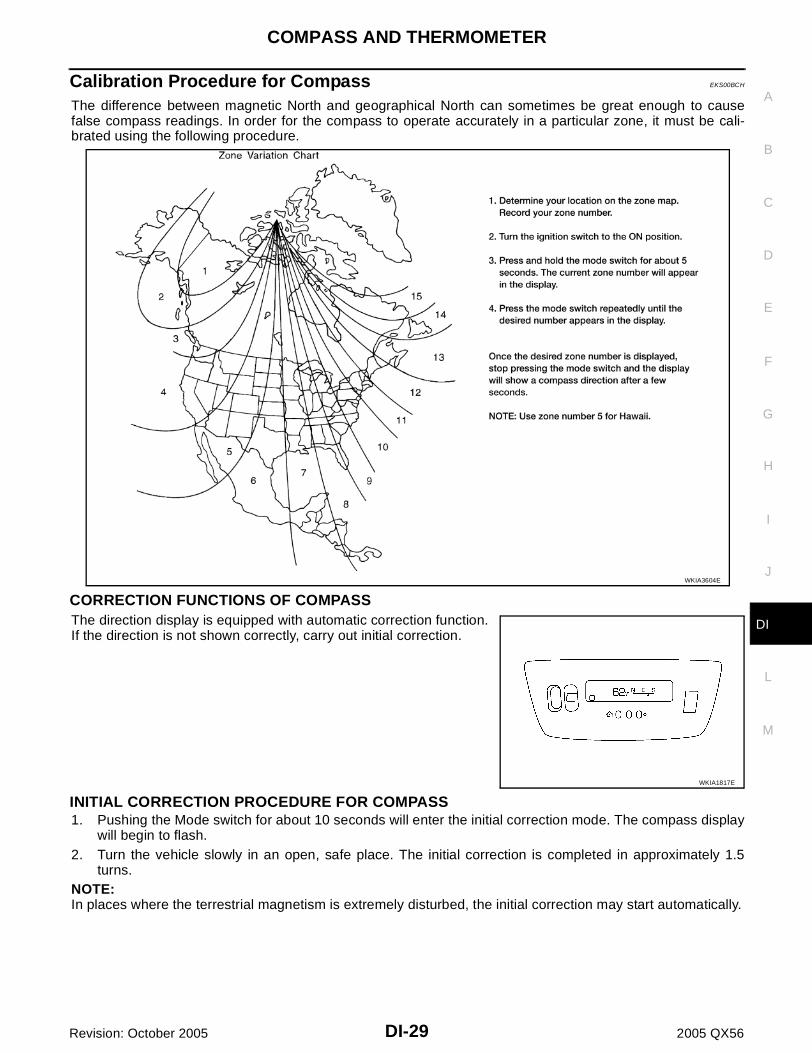
Calibration Procedure for Compass EKS00BCH
The difference between magnetic North and geographical North can sometimes be great enough to causefalse compass readings. In order for the compass to operate accurately in a particular zone, it must be cali-brated using the following procedure.
CORRECTION FUNCTIONS OF COMPASSThe direction display is equipped with automatic correction function.If the direction is not shown correctly, carry out initial correction.
INITIAL CORRECTION PROCEDURE FOR COMPASS1. Pushing the Mode switch for about 10 seconds will enter the initial correction mode. The compass display
will begin to flash.2. Turn the vehicle slowly in an open, safe place. The initial correction is completed in approximately 1.5
turns.NOTE:In places where the terrestrial magnetism is extremely disturbed, the initial correction may start automatically.
WKIA3604E
WKIA1817E

DI-30
WARNING LAMPS
Revision: October 2005 2005 QX56
WARNING LAMPS PFP:24814
Schematic EKS00BCI
WKWA4577E

WARNING LAMPS
DI-31
C
D
E
F
G
H
I
J
L
M
A
B
DI
Revision: October 2005 2005 QX56
Wiring Diagram — WARN — EKS00BCJ
WKWA2364E

DI-32
WARNING LAMPS
Revision: October 2005 2005 QX56
WKWA2366E

WARNING LAMPS
DI-33
C
D
E
F
G
H
I
J
L
M
A
B
DI
Revision: October 2005 2005 QX56
WKWA2367E

DI-34
WARNING LAMPS
Revision: October 2005 2005 QX56
WKWA2369E

WARNING LAMPS
DI-35
C
D
E
F
G
H
I
J
L
M
A
B
DI
Revision: October 2005 2005 QX56
WKWA2370E

DI-36
WARNING LAMPS
Revision: October 2005 2005 QX56
4WD Models
WKWA1172E

WARNING LAMPS
DI-37
C
D
E
F
G
H
I
J
L
M
A
B
DI
Revision: October 2005 2005 QX56
Oil Pressure Warning Lamp Stays Off (Ignition Switch ON) EKS00BCK
1. CHECK OIL PRESSURE SENSOR SIGNAL
1. Turn ignition switch ON.2. Check voltage between combination meter harness connector
M24 terminal 20 (Y) and ground.
OK or NGOK >> GO TO 2.NG >> GO TO 3.
2. CHECK OIL PRESSURE SENSOR GROUND CIRCUIT
1. Turn ignition switch OFF.2. Disconnect combination meter connector M24 and oil pressure
sensor connector F4.3. Check continuity between combination meter harness connector
M24 terminal 16 (B/P) and oil pressure sensor harness connec-tor F4 terminal 3 (B/P).
OK or NGOK >> Replace the combination meter. Refer to IP-13, "Combi-
nation Meter" .NG >> Repair harness or connector.
3. CHECK OIL PRESSURE SENSOR REFERENCE VOLTAGE
1. Turn ignition switch OFF.2. Disconnect oil pressure sensor connector F4.3. Turn ignition switch ON.4. Check voltage between combination meter harness connector
M24 terminal 22 (GR/L) and ground.
OK or NGOK >> GO TO 4.NG >> Replace the combination meter. Refer to IP-13, "Combi-
nation Meter" .
Terminals
Condition Voltage (V)(+)
(–)Connector
Terminal (Wire color)
M24 20 (Y) Ground
When ignition switch is in ON position. (Engine stopped)
Yes
Engine running. (Idle speed) YesWKIA1833E
Continuity should exist.
WKIA1837E
Voltage : Approx. 5V
WKIA1834E

DI-38
WARNING LAMPS
Revision: October 2005 2005 QX56
4. CHECK OIL PRESSURE SENSOR POWER SUPPLY CIRCUIT
1. Turn ignition switch OFF.2. Disconnect combination meter connector M24.3. Check continuity between combination meter harness connector M24 terminal 22 (GR/L) and oil pressure
sensor harness connector F4 terminal 1 (GR/L).
4. Check continuity between combination meter harness connectorM24 terminal 22 (GR/L) and ground.
OK or NGOK >> GO TO 5.NG >> Repair harness or connector.
5. CHECK OIL PRESSURE SENSOR SIGNAL CIRCUIT
1. Check continuity between combination meter harness connector M24 terminal 20 (Y) and oil pressuresensor harness connector F4 terminal 2 (Y).
2. Check continuity between combination meter harness connectorM24 terminal 20 (Y) and ground.
OK or NGOK >> GO TO 6.NG >> Repair harness or connector.
6. CHECK OIL PRESSURE SENSOR GROUND CIRCUIT
Check continuity between combination meter harness connectorM24 terminal 16 (B/P) and ground.
OK or NGOK >> Replace oil pressure sensor.NG >> Repair harness or connector.
Continuity should exist.
Continuity should not exist.
WKIA1835E
Continuity should exist.
Continuity should not exist.
WKIA1836E
Continuity should not exist.
WKIA2685E

WARNING LAMPS
DI-39
C
D
E
F
G
H
I
J
L
M
A
B
DI
Revision: October 2005 2005 QX56
Oil Pressure Warning Lamp Does Not Turn Off (Oil Pressure Is Normal) EKS00BCL
NOTE:For oil pressure inspection, refer to LU-7, "OIL PRESSURE CHECK" .
1. CHECK ENGINE OIL PRESSURE GAUGE OPERATION
Observe operation of engine oil pressure gauge.Does engine oil pressure gauge function properly?YES >> Replace the combination meter. Refer to IP-13, "Combination Meter" .NO >> Go to DI-19, "Engine Oil Pressure Signal Inspection" .

DI-40
A/T INDICATOR
Revision: October 2005 2005 QX56
A/T INDICATOR PFP:24814
Wiring Diagram — AT/IND — EKS00BCM
WKWA4578E

A/T INDICATOR
DI-41
C
D
E
F
G
H
I
J
L
M
A
B
DI
Revision: October 2005 2005 QX56
A/T Indicator Does Not Illuminate EKS00BCN
1. CHECK SELF-DIAGNOSIS OF COMBINATION METER
Perform combination meter self-diagnosis. Refer to DI-13, "SELF-DIAGNOSIS FUNCTION" .OK or NGOK >> GO TO 2.NG >> Replace the combination meter. Refer to IP-13, "Combination Meter" .
2. CHECK TCM
Perform self-diagnosis of TCM. Refer to AT-85, "SELF-DIAGNOSTIC RESULT MODE" .OK or NGOK >> Replace the combination meter. Refer to IP-13, "Combination Meter" .NG >> Refer to DI-13, "SELF-DIAGNOSIS FUNCTION" .
DI-42
WARNING CHIME
Revision: October 2005 2005 QX56
WARNING CHIME PFP:24814
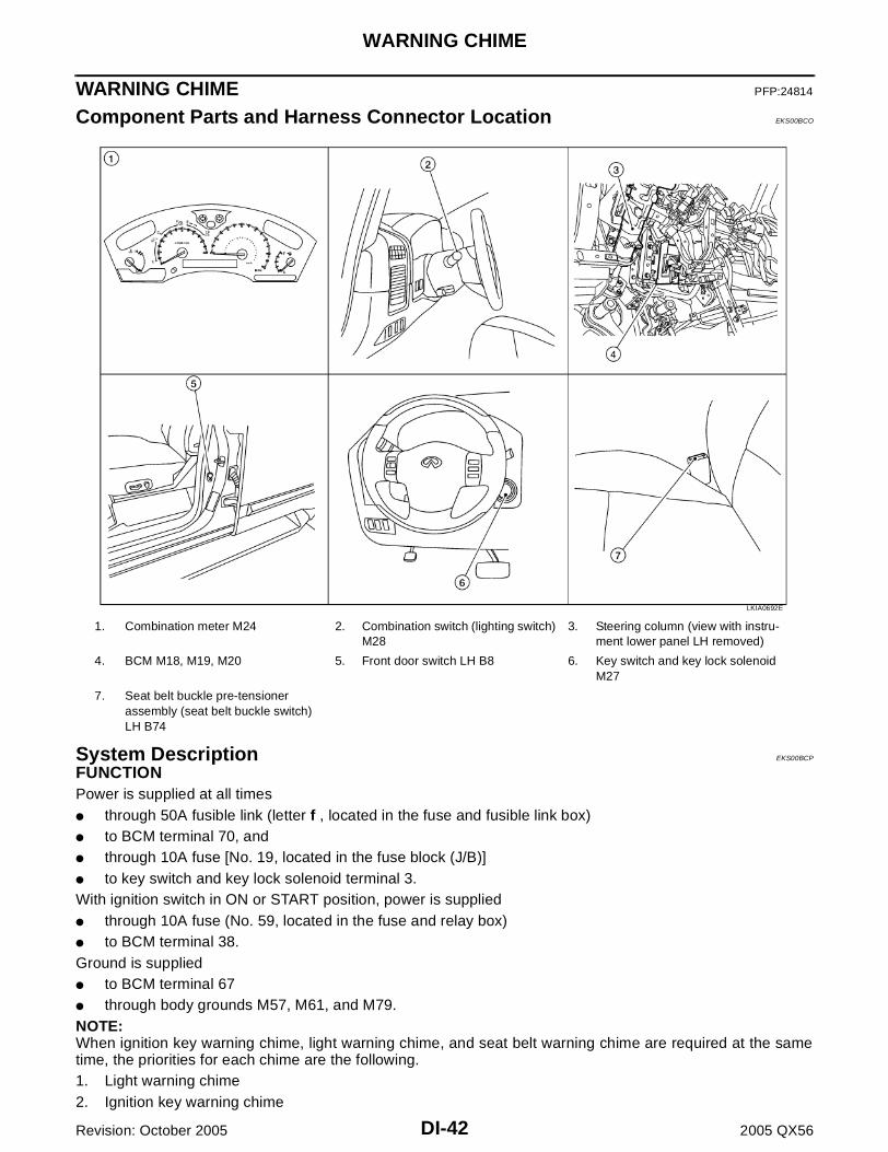
Component Parts and Harness Connector Location EKS00BCO
System Description EKS00BCP
FUNCTIONPower is supplied at all times through 50A fusible link (letter f , located in the fuse and fusible link box) to BCM terminal 70, and through 10A fuse [No. 19, located in the fuse block (J/B)] to key switch and key lock solenoid terminal 3.With ignition switch in ON or START position, power is supplied through 10A fuse (No. 59, located in the fuse and relay box) to BCM terminal 38.Ground is supplied to BCM terminal 67 through body grounds M57, M61, and M79.NOTE:When ignition key warning chime, light warning chime, and seat belt warning chime are required at the sametime, the priorities for each chime are the following.1. Light warning chime2. Ignition key warning chime
1. Combination meter M24 2. Combination switch (lighting switch) M28
3. Steering column (view with instru-ment lower panel LH removed)
4. BCM M18, M19, M20 5. Front door switch LH B8 6. Key switch and key lock solenoid M27
7. Seat belt buckle pre-tensioner assembly (seat belt buckle switch) LH B74
LKIA0692E

WARNING CHIME
DI-43
C
D
E
F
G
H
I
J
L
M
A
B
DI
Revision: October 2005 2005 QX56
3. Seat belt warning chime
IGNITION KEY WARNING CHIMEWith the key inserted in the ignition switch, the ignition switch in OFF position, and the driver's door open, thewarning chime will sound.Power is supplied through key switch and key lock solenoid terminal 4 to BCM terminal 37.Ground is supplied to BCM terminal 47 through front door switch LH terminal 2. Front door switch LH is case grounded.BCM detects key inserted into the ignition switch, and sends key warning signal to combination meter via CANcommunication lines. When the combination meter receives key warning signal, it sounds warning chime.
LIGHT WARNING CHIMEWith the key removed from the ignition switch, the driver's door open, and the lighting switch (part of the com-bination switch) in 1st or 2nd position, the warning chime will sound. [Except when headlamp battery savercontrol operates (5 minutes after ignition switch is turned to OFF or ACC position) and headlamps do not illu-minate.]Signal is supplied from combination switch (lighting switch) terminals 1, 2, 3, 4, 5, 6, 7, 8, 9 and 10 to BCM terminals 2, 3, 4, 5, 6, 32, 33, 34, 35 and 36.
NOTE:BCM detected lighting switch in 1st or 2nd position. Refer to BCS-3, "COMBINATION SWITCH READINGFUNCTION" .
Ground is supplied to BCM terminal 47 through front door switch LH terminal 2. Front door switch LH is case grounded.BCM detects headlamps are illuminated, and sends light warning signal to combination meter CAN communi-cation lines. When the combination meter receives light warning signal, it sounds warning chime.
SEAT BELT WARNING CHIMEWhen the ignition switch is turned ON with the seat belt unfastened [seat belt buckle pre-tensioner assembly(seat belt buckle switch) LH unfastened], warning chime will sound for approximately 6 seconds.Ground is supplied to combination meter terminal 27 through seat belt buckle pre-tensioner assembly (seat belt buckle switch) LH terminal 1.Seat belt buckle pre-tensioner assembly (seat belt buckle switch) LH terminal 2 is grounded through bodygrounds B7 and B19.The combination meter sends seat belt buckle switch LH unfastened signal to BCM via CAN communicationline.BCM receives seat belt buckle pre-tensioner assembly (seat belt buckle switch) LH unfastened signal fromcombination meter via CAN communication line, and sends seat belt warning signal to the combination metervia CAN communication line. When the combination meter receives the seat belt warning signal, it sounds thewarning chime. The BCM controls the (6 second) duration of the seat belt warning chime.
CAN Communication System Description EKS00BCQ
Refer to LAN-5, "CAN COMMUNICATION" .

DI-44
WARNING CHIME
Revision: October 2005 2005 QX56
Wiring Diagram — CHIME — EKS00BCR
WKWA2372E

WARNING CHIME
DI-45
C
D
E
F
G
H
I
J
L
M
A
B
DI
Revision: October 2005 2005 QX56
WKWA1175E

DI-46
WARNING CHIME
Revision: October 2005 2005 QX56
Terminals and Reference Value for BCM EKS00BCS
Terminal No.
Wire color
Item
ConditionReference value (V)
(Approx.)Ignition switch
Measurement method
2 SB Combination switch input 5 ON Light switch and wiper switch
OFF
Wiper dial position 4
3 G/Y Combination switch input 4 ON Light switch and wiper switch
OFF
Wiper dial position 4
4 Y Combination switch input 3 ON Light switch and wiper switch
OFF
Wiper dial position 4
5 G/B Combination switch input 2
ON Light switch and wiper switch
OFF
Wiper dial position 46 V Combination switch input 1
32 R/G Combination switch output 5 ON Light switch and wiper switch
OFF
Wiper dial position 4
33 R/Y Combination switch output 4 ON Light switch and wiper switch
OFF
Wiper dial position 4
34 L Combination switch output 3 ON Light switch and wiper switch
OFF
Wiper dial position 4
SKIA5291E
SKIA5292E
SKIA5291E
SKIA5292E
SKIA5291E
SKIA5292E
SKIA5291E

WARNING CHIME
DI-47
C
D
E
F
G
H
I
J
L
M
A
B
DI
Revision: October 2005 2005 QX56
Terminals and Reference Value for Combination Meter EKS00BCT
How to Proceed With Trouble Diagnosis EKS00BCU
1. Confirm the symptom or customer complaint.2. Understand operation description and function description. Refer to DI-42, "System Description" .3. Perform the preliminary check. Refer to DI-47, "Preliminary Check" .4. Check symptom and repair or replace the cause of malfunction.5. Does the warning chime operate properly? If so, go to 6. If not, go to 3.6. Inspection End.
Preliminary Check EKS00BCV
INSPECTION FOR POWER SUPPLY AND GROUND CIRCUIT
1. CHECK FUSE AND FUSIBLE LINK
Check for blown BCM fuse or fusible link.
Refer to DI-44, "Wiring Diagram — CHIME —" .
OK or NGOK >> GO TO 2.NG >> If fuse is blown, be sure to eliminate cause of malfunction before installing new fuse. Refer to PG-
4, "POWER SUPPLY ROUTING CIRCUIT" .
35 O/B Combination switch output 2
ON Light switch and wiper switch
OFF
Wiper dial position 436 R/W Combination switch output 1
37 B/R Key switch signal OFFKey is removed 0
Key is inserted Battery voltage
38 W/L Ignition switch ON or START ON — Battery voltage
39 L CAN-H — — —
40 P CAN-L — — —
47 SB Front door switch LH signal OFFON (open) 0
OFF (closed) 5
67 B Ground OFF — 0
70 W/B Battery power supply OFF — Battery voltage
Terminal No.
Wire color
Item
ConditionReference value (V)
(Approx.)Ignition switch
Measurement method
SKIA5292E
Terminal No.
Wire color
Item
ConditionReference value (V)
(Approx.)Ignition switch
Measurement method
11 L CAN-H — — —
12 P CAN-L — — —
27 O/BSeat belt buckle pre-ten-sioner assembly (seat belt buckle switch) LH
ONUnfastened (ON) 0
Fastened (OFF) Battery voltage
Unit Power source Fuse or fusible link No.
BCMBattery f
Ignition switch ON or START 59

DI-48
WARNING CHIME
Revision: October 2005 2005 QX56
2. CHECK POWER SUPPLY CIRCUIT
1. Disconnect BCM connectors M18 and M20.2. Check voltage between BCM harness connector terminals and
ground.
OK or NGOK >> GO TO 3.NG >> Check harness for open between BCM and fuse.
3. CHECK GROUND CIRCUIT
1. Turn ignition switch OFF. 2. Check continuity between BCM harness connector M20 terminal
67 (B) and ground.
OK or NGOK >> Inspection End.NG >> Repair harness or connector.
Terminals Ignition switch position
(+)
(–) OFF ONConnector
Terminal (Wire color)
M20 70 (W/B)
Ground
Battery volt-age
Battery volt-age
M18 38 (W/L) 0VBattery volt-
age
WKIA2072E
Continuity should exist.
LIIA0915E

WARNING CHIME
DI-49
C
D
E
F
G
H
I
J
L
M
A
B
DI
Revision: October 2005 2005 QX56
CONSULT-II Function (BCM) EKS00BCW
CONSULT-II can display each diagnostic item using the diagnostic test modes shown following.
CONSULT-II BASIC OPERATION PROCEDURECAUTION:If CONSULT-II is used with no connection of CONSULT-II CONVERTER, malfunctions might bedetected in self-diagnosis depending on control unit which carries out CAN communication.1. With the ignition switch OFF, connect “CONSULT-II” and “CON-
SULT-II CONVERTER” to the data link connector, and turn igni-tion switch ON.
2. Touch “START (NISSAN BASED VHCL)”.
3. Touch “BCM” on “SELECT SYSTEM” screen. If “BCM” is notindicated, go to BCS-11, "CONSULT–II INSPECTION PROCE-DURE" .
BCMdiagnostic test item
Diagnostic mode Description
Inspection by part
WORK SUPPORTSupports inspections and adjustments. Commands are transmitted to the BCM for setting the status suitable for required operation, input/output signals are received from the BCM and received data is displayed.
DATA MONITOR Displays BCM input/output data in real time.
ACTIVE TEST Operation of electrical loads can be checked by sending drive signal to them.
SELF-DIAG RESULTS Displays BCM self-diagnosis results.
CAN DIAG SUPPORT MNTR The result of transmit/receive diagnosis of CAN communication can be read.
ECU PART NUMBER BCM part number can be read.
CONFIGURATION Performs BCM configuration read/write functions.
BBIA0369E
BCIA0029E
BCIA0030E

DI-50
WARNING CHIME
Revision: October 2005 2005 QX56
4. Touch “BUZZER” or “BCM”.
5. Select “DATA MONITOR” or “SELF-DIAG RESULTS”.
DATA MONITOROperation Procedure1. Touch “BUZZER” on “SELECT TEST ITEM” screen.2. Touch “DATA MONITOR” on “SELECT DIAG MODE” screen.3. Touch “ALL SIGNALS” or “SELECTION FROM MENU” on “DATA MONITOR” screen.
4. If “SELECTION FROM MENU” is selected, touch the item you desire to monitor. If “ALL SIGNALS” isselected, all control items are monitored.
5. Touch “START”.6. During monitoring, touching “RECORD” can start recording the monitored item status.
Display Item List
ACTIVE TESTOperation Procedure1. Touch “BUZZER” on “SELECT TEST ITEM” screen.2. Touch “ACTIVE TEST” on “SELECT DIAG MODE” screen.3. Touch the item to be tested, and check the operation.4. During the operation check, touching “OFF” deactivates the operation.
SKIA5788E
BCIA0031E
ALL SIGNALS Monitors main items.
SELECTION FROM MENU Selects and monitors items.
Monitored item Description
IGN ON SW Indicates [ON/OFF] condition of ignition switch.
KEY ON SW Indicates [ON/OFF] condition of key switch.
DOOR SW-DR Indicates [ON/OFF] condition of front door switch (driver side).
LIGHT SW 1ST Indicates [ON/OFF] condition of lighting switch.
BUCKLE SW Indicates [ON/OFF] condition of seat belt buckle switch LH.

WARNING CHIME
DI-51
C
D
E
F
G
H
I
J
L
M
A
B
DI
Revision: October 2005 2005 QX56
Display Item List
SELF-DIAGNOSTIC RESULTSOperation Procedure1. Touch “BCM” on "SELECT TEST ITEM” screen.2. Touch “SELF-DIAG RESULTS” on “SELECT DIAG MODE” screen.3. Self-diagnostic results are displayed.
Display Item List
All Warning Chimes Do Not Operate EKS00BCX
1. CHECK BCM CHIME OPERATION
Select “BUZZER” on CONSULT-II, and perform “LIGHT WARNALM”, "IGN KEY WARN ALM", OR "SEAT BELT WARN TEST"active test.Does chime sound?YES >> Replace the BCM. Refer to BCS-20, "Removal and
Installation of BCM" .NO >> Replace the combination meter. Refer to DI-25,
"Removal and Installation of Combination Meter" .
Test item Malfunction is detected when···
LIGHT WARN ALMThis test is able to check light warning chime operation. Light warning chime sounds for 2 sec-onds after touching “ON” on CONSULT-II screen.
IGN KEY WARN ALMThis test is able to check key warning chime operation. Key warning chime sounds for 2 seconds after touching “ON” on CONSULT-II screen.
SEAT BELT WARN TESTThis test is able to check seat belt warning chime operation. Seat belt warning chime sounds for 2 seconds after touching “ON” on CONSULT-II screen.
Monitored Item CONSULT-II display Description
CAN communication CAN communication [U1000] Malfunction is detected in CAN communication.
CAN communication system CAN communication system 1 to 6 [U1000] Malfunction is detected in CAN system.
SKIA6331E

DI-52
WARNING CHIME
Revision: October 2005 2005 QX56
Key Warning Chime and Light Warning Chime Do Not Operate (Seat Belt Warn-ing Chime Does Operate) EKS00BCY
1. CHECK BCM INPUT SIGNAL
With CONSULT-II1. Select "BCM" on CONSULT-II. 2. With "DATA MONITOR" of "BUZZER", confirm "DOOR SW-DR"
changes with the status of front door LH.
Without CONSULT-IICheck voltage between BCM harness connector M19 terminal 47(SB) and ground.
OK or NGOK >> Replace the BCM. Refer to BCS-20, "Removal and
Installation of BCM" .NG >> GO TO 2.
2. CHECK FRONT DOOR SWITCH LH CIRCUIT
1. Turn ignition switch OFF.2. Disconnect BCM connector M19 and front door switch LH con-
nector B8.3. Check continuity between BCM harness connector M19 terminal
47 (SB) and front door switch LH harness connector B8 terminal2 (SB).
4. Check continuity between BCM harness connector M19 terminal47 (SB) and ground.
OK or NGOK >> GO TO 3.NG >> Repair harness or connector.
When front door LH is opened
: DOOR SW-DR ON
When front door LH is closed
: DOOR SW-DR OFF
LKIA0335E
When front door LH is opened
: Approx. 0V
When front door LH is closed
: Approx. 5V
WKIA1515E
Continuity should exist.
Continuity should not exist.WKIA1516E

WARNING CHIME
DI-53
C
D
E
F
G
H
I
J
L
M
A
B
DI
Revision: October 2005 2005 QX56
3. CHECK FRONT DOOR SWITCH LH
Check continuity between front door switch LH terminal 2 andexposed metal of switch while pressing and releasing switch.
OK or NGOK >> Replace the BCM. Refer to BCS-20, "Removal and
Installation of BCM" .NG >> Replace the front door switch LH.
Key Warning Chime Does Not Operate EKS00BCZ
1. CHECK FUSE
Check if the key switch fuse [No. 19, located in the fuse block (J/B)] is blown. Refer to DI-44, "Wiring Diagram— CHIME —" .Is the fuse blown?YES >> Replace the fuse. Be sure to repair the cause of malfunction before installing new fuse.NO >> GO TO 2.
2. CHECK WARNING CHIME OPERATION
With key removed from the ignition key cylinder and the front door LH open, turn the lighting switch to 1st or2nd position.Does warning chime sound?YES >> GO TO 3.NO >> Go to DI-51, "All Warning Chimes Do Not Operate" or DI-52, "Key Warning Chime and Light
Warning Chime Do Not Operate (Seat Belt Warning Chime Does Operate)" .
When front door switch LH is released
: Continuity should exist.
When front door switch LH is pressed
: Continuity should not exist.
WKIA2023E

DI-54
WARNING CHIME
Revision: October 2005 2005 QX56
3. CHECK BCM INPUT SIGNAL
With CONSULT-IIWith "DATA MONITOR" of "BUZZER", confirm "KEY ON SW"changes when the key is inserted/removed from the ignition key cyl-inder.
Without CONSULT-IICheck voltage between BCM harness connector M18 terminal 37 (B/R) and ground.
OK or NGOK >> Replace the BCM. Refer to BCS-20, "Removal and
Installation of BCM" .NG >> GO TO 4.
4. CHECK KEY SWITCH
1. Turn ignition switch OFF.2. Disconnect key switch and key lock solenoid connector.3. Check continuity between key switch and key lock solenoid con-
nector M27 terminals 3 and 4.
OK or NGOK >> GO TO 5.NG >> Replace the key switch and key lock solenoid.
When key is inserted in ignition key cylinder
: KEY ON SW ON
When key is removed from ignition key cylinder
: KEY ON SW OFF
SKIA1960E
Terminals
Condition Voltage (V)(+)
(–)Connector
Terminal (Wire color)
M18 37 (B/R) GroundKey is inserted Battery voltage
Key is removed 0
LKIA0255E
Terminals Condition Continuity
3 4Key is inserted Yes
Key is removed No
WKIA1820E

WARNING CHIME
DI-55
C
D
E
F
G
H
I
J
L
M
A
B
DI
Revision: October 2005 2005 QX56
5. CHECK KEY SWITCH CIRCUIT
1. Disconnect BCM.2. Check continuity between BCM harness connector M18 terminal
37 (B/R) and key switch and key lock solenoid harness connec-tor M27 terminal 4 (B/R).
3. Check continuity between BCM harness connector M18 terminal37 (B/R) and ground.
OK or NGOK >> GO TO 6.NG >> Repair harness or connector.
6. CHECK KEY SWITCH POWER SUPPLY CIRCUIT
Check voltage between key switch and key lock solenoid harnessconnector M27 terminal 3 (Y/R) and ground.
OK or NGOK >> Replace the BCM. Refer to BCS-20, "Removal and
Installation of BCM" .NG >> Check harness for open or short between fuse and key
switch and key lock solenoid.
Light Warning Chime Does Not Operate EKS00BD0
1. CHECK WARNING CHIME OPERATION
Check key warning chime and seat belt warning chime functions.Do key warning chime and seat belt warning chime sound?YES >> GO TO 2.NO >> Go to DI-51, "All Warning Chimes Do Not Operate" .
2. CHECK BCM INPUT SIGNAL
With CONSULT-II1. Select "BCM".2. With "DATA MONITOR" of "BUZZER", confirm "LIGHT SW 1ST"
status changes when the lighting switch is moved from ON (1stposition) to OFF.
Without CONSULT-IICheck combination switch. Refer to LT-98, "Combination SwitchReading Function" .OK or NGOK >> Replace the BCM. Refer to BCS-20, "Removal and Installation of BCM" .NG >> Check lighting switch. Refer to LT-98, "Combination Switch Reading Function" .
Continuity should exist.
Continuity should not exist.WKIA2074E
Battery voltage should exist.
WKIA2075E
Lighting switch ON (1st position) : LIGHT SW 1ST ON
Lighting switch OFF : LIGHT SW 1ST OFF
WKIA1877E

DI-56
WARNING CHIME
Revision: October 2005 2005 QX56
Seat Belt Warning Chime Does Not Operate EKS00BD1
1. CHECK WARNING CHIME OPERATION
1. With key removed from the ignition and the front door LH open, turn the lighting switch to 1st or 2nd posi-tion.
2. Return lighting switch to OFF position, and insert key into ignition.Does warning chime sound for both steps?
YES >> GO TO 2.NO >> Go to DI-51, "All Warning Chimes Do Not Operate" .
2. CHECK SEAT BELT WARNING LAMP OPERATION
Turn ignition switch ON. Buckle and unbuckle the driver seat belt while watching seat belt warning lamp.
OK or NGOK >> Replace the BCM. Refer to BCS-20, "Removal and Installation of BCM" .NG >> GO TO 3.
3. CHECK COMBINATION METER INPUT SIGNAL
1. Turn ignition switch ON.2. Check voltage between combination meter harness connector
M24 terminal 27 (O/B) and ground.
OK or NGOK >> Replace the combination meter. Refer to IP-13, "Combination Meter" .NG >> GO TO 4.
4. CHECK SEAT BELT BUCKLE SWITCH
1. Turn ignition switch OFF.2. Disconnect seat belt buckle pre-tensioner assembly (seat belt
buckle switch) LH connector.3. Check continuity between seat belt buckle pre-tensioner assem-
bly (seat belt buckle switch) LH terminals 1 and 2.
OK or NGOK >> GO TO 5.NG >> Replace the seat belt buckle pre-tensioner assembly (seat belt buckle switch) LH.
When seat belt is fastened : Warning lamp OFF
When seat belt is unfastened : Warning lamp ON
Terminals
ConditionVoltage (V)(Approx.)
(+)
(–)Connector
Terminal (Wire color)
M24 27 (O/B) GroundSeat belt is fastened Battery voltage
Seat belt is unfastened 0WKIA1821E
Terminals Condition Continuity
1 2Seat belt is fastened No
Seat belt is unfastened Yes
WKIA3607E

WARNING CHIME
DI-57
C
D
E
F
G
H
I
J
L
M
A
B
DI
Revision: October 2005 2005 QX56
5. CHECK SEAT BELT BUCKLE SWITCH CIRCUIT
1. Disconnect combination meter connector.2. Check continuity between combination meter harness connector
M24 terminal 27 (O/B) and seat belt buckle pre-tensionerassembly (seat belt buckle switch) LH harness connector B74terminal 1 (O/B).
3. Check continuity between combination meter harness connectorM24 terminal 27 (O/B) and ground.
OK or NGOK >> Check seat belt buckle pre-tensioner assembly (seat belt buckle switch) LH ground circuit.NG >> Repair harness or connector.
Continuity should exist.
Continuity should not exist.WKIA2077E

DI-58
REAR SONAR SYSTEM
Revision: October 2005 2005 QX56
REAR SONAR SYSTEM PFP:28532
Component Parts and Harness Connector Location EKS00BD2
1. Back-up lamp relay E45 2. Battery 3. Sonar buzzer M117
4. Rear sonar system OFF switch M116 5. Sonar control unit B56 6. Rear sonar sensor LH outer C102
7. Rear sonar sensor LH inner C103 8. Rear sonar sensor RH inner C104 9. Rear sonar sensor RH outer C105
10. A/T assembly F9
LKIA0693E

REAR SONAR SYSTEM
DI-59
C
D
E
F
G
H
I
J
L
M
A
B
DI
Revision: October 2005 2005 QX56
System Description EKS00BD3
FUNCTIONWith the ignition switch in the ON or START position, power is supplied through 10A fuse [No. 12 , located in the fuse block (J/B)] to sonar control unit terminal 8, and through 10A fuse (No. 51, located in the IPDM E/R) to back-up lamp relay terminals 1 and 3.Ground is supplied to sonar control unit terminal 6 through body grounds B7 and B19.With the ignition switch in the ON or START position, and the transmission gear selector lever in the R posi-tion, power is supplied to sonar control unit terminal 5 from back-up lamp relay terminal 5.With power and ground supplied, transmission gear selector lever in R position, and the rear sonar systemOFF switch ON, the rear sonar system will detect obstacles within 1.8 m (5.9 ft.) of the rear sonar sensors.The vehicle operator is notified of obstacles by varied rate of tone from the sonar buzzer depending on dis-tance of obstacle being sensed.
REAR SONAR SYSTEM OFF SWITCHWith power and ground supplied to the sonar control unit, transmission gear selector lever in R position, thesonar system can be disabled and the sonar buzzer silenced by momentarily pressing the rear sonar systemOFF switch. The rear sonar system OFF indicator lamp will be illuminated in the rear sonar system OFFswitch. To disable the rear sonar system, ground is supplied to sonar control unit terminal 13 through rear sonar system OFF switch terminal 1 through rear sonar system OFF switch terminal 2 from body grounds M57, M61, and M79.To light the rear sonar system OFF indicator, power is supplied from sonar control unit terminal 4 to the rear sonar system OFF switch terminal 5.Ground is supplied to the rear sonar system OFF switch terminal 6 from body grounds M57, M61, and M79.The rear sonar system and buzzer will be disabled and the rear sonar system OFF indicator will be illuminateduntil the ignition switch is turned OFF. When the ignition switch is turned ON, the rear sonar system will beenabled. Depressing the rear sonar system OFF switch momentarily will enable the rear sonar system also.Enabling the rear sonar system will cause the rear sonar system OFF indicator to go out.
SONAR BUZZERWith power supplied to the sonar control unit and the transmission gear selector lever in R position, a station-ary object that is at least 7.0 cm (2.8 in.) wide and 1.0 m (39.0 in.) tall and that is closer than 1.8 meters (5.9 ft.)will be detected by the rear sonar sensors, causing the sonar buzzer to sound a tone. As the vehicle movescloser to the object, the rate of the tone will increase. When the object is less than 25.0 cm (10 in.) from therear bumper, the tone will sound continuously.Power is supplied to sonar buzzer terminal + from sonar control unit terminal 7.Ground is supplied to sonar buzzer terminal - from sonar control unit terminal 3.

DI-60
REAR SONAR SYSTEM
Revision: October 2005 2005 QX56
REAR SONAR SENSORWith power and ground supplied to the rear sonar sensors, the sonar sensors transmit a 38.4 kHz ultrasonicsignal. This signal is reflected back to the sensor by objects large enough and close enough to be detected.The rear sonar sensors measure the time from the transmitted signal to the time the signal is reflected backand sends this information to the sonar control unit.Power is supplied to each rear sonar sensor terminal 1 from sonar control unit terminal 16.Ground is supplied to each rear sonar sensor terminal 3 from sonar control unit terminal 15.Signal is supplied to sonar control unit terminals 9, 10, 11 and 12. from each rear sonar sensor terminal 2

REAR SONAR SYSTEM
DI-61
C
D
E
F
G
H
I
J
L
M
A
B
DI
Revision: October 2005 2005 QX56
Wiring Diagram — SONAR — EKS00BD4
WKWA2373E

DI-62
REAR SONAR SYSTEM
Revision: October 2005 2005 QX56
WKWA1177E

REAR SONAR SYSTEM
DI-63
C
D
E
F
G
H
I
J
L
M
A
B
DI
Revision: October 2005 2005 QX56
Terminals And Reference Value For Sonar Control Unit EKS00BD5
How to Proceed With Trouble Diagnosis EKS00BD6
1. Confirm the symptom or customer complaint.2. Understand operation description and function description. Refer to DI-59, "System Description" .3. Perform pre-diagnosis inspection. Refer to DI-64, "Pre-diagnosis Inspection" .4. Perform self-diagnosis. Refer to DI-64, "Self-diagnosis Function" .5. Perform the preliminary check. Refer to DI-66, "Preliminary Check" .6. Check symptom and repair or replace the cause of malfunction. Refer to DI-67, "Symptom Chart" .7. Does the rear sonar system operate properly? If so, go to 8. If not, go to 3.8. Clear fault codes. Refer to DI-65, "IDLING OR CLEARING FAULT CODES MODE" .9. Inspection End.
TERMINAL(COLOR)
ITEM
CONDITIONReference value (V)
(Approx.)IGNITION SWITCH
OPERATION
3 (R) Sonar buzzer return ON — 0 - 12 (variable)
4 (BR/Y)Rear sonar system OFF indicator output
ONRear sonar system OFF
switch
ON 0
OFF 12
5 (G/W) Reverse signal ON
Transmission gear selector lever
R position 12
Transmission gear selector lever
Not R position 0
6 (B)Sonar control unit ground
— — 0
7 (L) Sonar buzzer drive signal
ON — 12
8 (G/R)Sonar control unit power
ON — 12
9 (GR)Rear sonar sensor signal - RH outer
ON
Rear sonar system OFF switch ON
Transmission gear selector lever in R position
No obstacles
12
10 (P)Rear sonar sensor signal - LH outer
ON
Rear sonar system OFF switch ON
Transmission gear selector lever in R position
No obstacles
12
11 (O)Rear sonar sensor signal - LH inner
ON
Rear sonar system OFF switch ON
Transmission gear selector lever in R position
Distance obstacles
12
12 (LG)Rear sonar sensor signal - RH inner
ON
Rear sonar system OFF switch ON
Transmission gear selector lever in R position
Distance obstacles
12
13 (LG)Rear sonar system OFF switch signal
ONRear sonar system OFF switch
ON 0
OFF 12
15 (Y)Rear sonar sensor ground
ON — 0
16 (LG/B)Rear sonar sensor power
ON Ignition switch ON 12

DI-64
REAR SONAR SYSTEM
Revision: October 2005 2005 QX56
Pre-diagnosis Inspection EKS00BD7
SENSOR STATUS CHECK Check that the rear sonar sensor is properly aligned (bumper is not misaligned, no deformation in sensor
mounting area. Check that snow, mud, or other foreign objects are not adhering to the rear sonar sensor. Check that there is no deformation, scratches, or other damage to the rear sonar sensor. Check that water has not accumulated in the rear sonar sensor.CAUTION:Use water, cotton swab, or other soft material for cleaning the sensor.1. Check that there are no obstacles within each rear sonar sensor's detection range.
2. Check that there are no nearby ultrasound sources (such as the sounds of vehicle horns, motorcycleengines, or truck air brakes).
3. Check that the vehicle is on a level surface.
Self-diagnosis Function EKS00BD8
There are four modes of self-diagnosis; entering diagnostics, requesting number of fault codes, requestingfault codes, and idling or clearing fault codes. These steps must be followed in order. Self-diagnosis can bemanually exited by turning the ignition switch OFF, or selecting reverse gear. Self-diagnosis will exit unless afault code request occurs before a message is repeated five times without acknowledgement.
ENTERING DIAGNOSTICS MODE1. Turn ignition switch ON. Rear sonar system OFF switch indica-
tor lamp illuminates for three seconds and then turns off.2. Immediately push rear sonar system OFF switch ten times
within five seconds.3. The sonar buzzer will sound once and the rear sonar system
OFF indicator will flash once.
REQUESTING NUMBER OF FAULT CODES MODE1. While in diagnostic mode, push rear sonar system OFF switch
once.2. The sonar buzzer will sound once.3. Rear sonar system OFF indicator will flash once and sonar
buzzer will sound once for each fault code detected. 4. There will be a four second pause.5. The number of fault codes will repeat five times then pause.
NOTE:Self-diagnosis will exit unless requesting fault codes occursbefore five repeats ends.
Detection range
Rear sonar sensors Approx. 1.8 m (5.9 ft.) maximum
LKIA0389E
LKIA0388E

REAR SONAR SYSTEM
DI-65
C
D
E
F
G
H
I
J
L
M
A
B
DI
Revision: October 2005 2005 QX56
REQUESTING FAULT CODES MODE1. While in "requesting number of fault codes" mode, push rear
sonar system OFF switch once.2. The sonar buzzer will sound once.3. Rear sonar system OFF indicator will flash and sonar buzzer will
sound the first digit of the fault code followed by a one secondpause.
4. Rear sonar system OFF indicator will flash and sonar buzzer willsound the second digit of the fault code followed by a four sec-ond pause.
5. The fault codes will repeat five times then pause.NOTE:Requesting fault codes will exit unless the fault code is acknowledged before five repeats ends.The fault code is acknowledged by pushing the rear sonar system OFF switch once (the sonar buzzermay sound). When all fault codes have been indicated, idle mode will be entered. See the following tablefor fault code identification.
IDLING OR CLEARING FAULT CODES MODENOTE:While in idle mode, self-diagnosis will automatically exit if no activity occurs for thirty seconds.1. Push and hold rear sonar system OFF switch for three seconds
to reset time-out counter.2. Push and hold rear sonar system OFF switch for three seconds
to clear codes.
Fault Code Malfunction Page Reference
1 1Rear sonar sensor LH outer
Check harness for open or short. If NG repair or replace harness. If OK replace sensor. Refer to DI-68, "REAR SONAR SENSORS" .
1 2Rear sonar sensor LH inner
1 3Rear sonar sensor RH inner
1 4Rear sonar sensor RH outer
2 1 Sonar buzzer DI-68, "SONAR BUZZER"
2 2Rear sonar system OFF indicator
DI-68, "REAR SONAR SYSTEM OFF INDICA-TOR"
2 3Rear sonar system OFF switch
DI-68, "REAR SONAR SYSTEM OFF SWITCH"
2 4 Sonar control unit
Replace sonar control unit. Refer to DI-68, "SONAR CONTROL UNIT"
LKIA0390E
LKIA0391E

DI-66
REAR SONAR SYSTEM
Revision: October 2005 2005 QX56
Preliminary Check EKS00BD9
INSPECTION FOR POWER SUPPLY AND GROUND CIRCUIT
1. CHECK FUSE
Check for blown rear sonar system fuse.
Refer to DI-61, "Wiring Diagram — SONAR —" .OK or NG
OK >> GO TO 2.NG >> If fuse is blown, be sure to eliminate cause of problem before installing new fuse. Refer to PG-4,
"POWER SUPPLY ROUTING CIRCUIT" .
2. CHECK POWER SUPPLY CIRCUIT
1. Disconnect sonar control unit connector.2. Check voltage between sonar control unit connector B56 termi-
nal 8 (G/R) and ground.
OK or NGOK >> GO TO 3.NG >> Check harness for open between sonar control unit and fuse.
3. CHECK GROUND CIRCUIT
1. Turn ignition switch OFF.2. Check continuity between sonar control unit B56 terminal 6 and
ground.
OK or NGOK >> Inspection End.NG >> Check harness ground circuit.
Unit Power Source Fuse
Sonar control unit ON or START 12
Terminals Ignition switch position
(+)
(-) ON or STARTConnector
Terminal(Wire color)
B56 8 (G/R) Ground Battery voltage
WKIA1145E
Terminals
Continuity(+)
(–)Connector
Terminal(Wire color)
B56 6 (B) Ground Yes
WKIA1146E

REAR SONAR SYSTEM
DI-67
C
D
E
F
G
H
I
J
L
M
A
B
DI
Revision: October 2005 2005 QX56
Symptom Chart EKS00BDA
Symptom Repair order
When the rear sonar system OFF switch is OFF, the indicator lamp does not light and the buzzer does not sound.
1. Check rear sonar system OFF switch for malfunction. Refer to DI-68, "REAR SONAR SYSTEM OFF SWITCH" .
2. Check rear sonar system OFF switch ground circuit.
3. Check harness and connections between rear sonar system OFF switch and sonar control unit.
4. Replace sonar control unit. Refer to DI-68, "SONAR CON-TROL UNIT" .
When the rear sonar system OFF switch is OFF, the indicator lamp does not light but buzzer sounds.
1. Check rear sonar system OFF indicator for malfunction. Refer to DI-68, "REAR SONAR SYSTEM OFF INDICATOR" .
2. Check harness and connections between rear sonar system OFF indicator and sonar control unit.
3. Replace sonar control unit. Refer to DI-68, "SONAR CON-TROL UNIT" .
When the rear sonar system OFF switch is OFF, the sonar buzzer does not sound but indicator lamp illuminates.
1. Check sonar buzzer. Refer to DI-68, "SONAR BUZZER" .
2. Check harness and connections between sonar buzzer and sonar control unit.
3. Replace sonar control unit. Refer to: DI-68, "SONAR CON-TROL UNIT" .
When rear sonar system OFF switch is ON, the rear sonar sys-tem OFF indicator lamp lights up and the sonar buzzer sounds intermittently (for about 4 seconds).
1. Check harness between rear sonar sensors and sonar control unit for an open condition.
2. Check rear sonar sensors for malfunction.
3. Replace sonar control unit. Refer to DI-68, "SONAR CON-TROL UNIT" .
The rear sonar system operates with the rear sonar system OFF switch OFF.
1. Check rear sonar system OFF switch for malfunction. Refer to DI-68, "REAR SONAR SYSTEM OFF SWITCH" .
2. Check rear sonar system OFF switch ground circuit.
3. Check harness and connections between rear sonar system OFF switch and sonar control unit.
4. Replace sonar control unit. Refer to DI-68, "SONAR CON-TROL UNIT" .
When the transmission gear selector lever is in the R position and the rear sonar system OFF switch is OFF, the sonar system does not operate.
1. Check for PNP switch failure. Refer to AT-85, "SELF-DIAG-NOSTIC RESULT MODE" .
2. Check harness and connections between sonar control unit and PNP/reverse lamp circuits.
3. Replace sonar control unit. Refer to DI-68, "SONAR CON-TROL UNIT" .
When the rear sonar system OFF switch is OFF, the indicator lamp lights up and buzzer sounds although there is no obstacle within the detection range.
1. Check for adhesion of snow, mud, or other foreign objects to rear sonar sensors; dew condensation; etc. Refer to DI-64, "Pre-diagnosis Inspection" .
2. Check that the rear sonar sensor is properly aligned (bumper is not misaligned, no deformation in sensor mounting area).
3. Check harness and connections between rear sonar sensors and sonar control unit.
4. Check rear sonar sensors for malfunction.
5. Replace sonar control unit. Refer to DI-68, "SONAR CON-TROL UNIT" .
The rear sonar sensors do not operate according to the distance between each sensor and the obstacle. (There is a large error in the obstacle detection distance).
1. Check rear sonar sensors for malfunction.
2. Replace sonar control unit. Refer to DI-68, "SONAR CON-TROL UNIT" .
3. Check for adhesion of snow, mud, or other foreign objects to rear sonar sensors; dew condensation; etc. Refer to DI-64, "Pre-diagnosis Inspection" .
4. Check that the rear sonar sensor is properly aligned (bumper is not misaligned, no deformation in sensor mounting area).

DI-68
REAR SONAR SYSTEM
Revision: October 2005 2005 QX56
Component Inspection EKS00BDB
SONAR BUZZER1. Disconnect the sonar buzzer connector.2. Check continuity between buzzer connector M117 terminal (+)
and terminal (-)
REAR SONAR SYSTEM OFF SWITCHDisconnect the rear sonar system OFF switch connector M116.Check continuity between the following terminals.
REAR SONAR SYSTEM OFF INDICATORDisconnect the rear sonar system OFF switch connector M116, andapply battery voltage (approx. 12V) to terminal 5. Check the rearsonar system OFF indicator operation when terminal 6 is connectedto battery ground.
Removal and Installation of Rear Sonar System EKS00BDC
REAR SONAR SENSORSRefer to EI-15, "Removal and Installation" for rear sonar sensor removal and installation procedures.
SONAR CONTROL UNIT1. Remove luggage side finisher LH. Refer to EI-40, "LUGGAGE FLOOR TRIM" to gain access to sonar
control unit.2. Disconnect electrical connector then remove sonar control unit. Refer to DI-58, "Component Parts and
Harness Connector Location" .3. Installation is in the reverse order of removal.
(+) - (-) : Continuity should exist.
WKIA2024E
Rear sonar system OFF switch
Terminal to be inspected Continuity
Depressed1 - 2
Yes
Released No
WKIA2025E
Terminal to be inspected
Condition Operation
Rear sonar sys-tem OFF switch
5 Approx. 12V Rear sonar system OFF indicator lights6 Ground
WKIA2026E

CLOCK
DI-69
C
D
E
F
G
H
I
J
L
M
A
B
DI
Revision: October 2005 2005 QX56
CLOCK PFP:25820
Wiring Diagram — CLOCK — EKS00BDD
WKWA1178E

DI-70
CLOCK
Revision: October 2005 2005 QX56
Removal and Installation of Clock EKS00BDE
REMOVAL1. Remove cluster lid C. Refer to IP-10, "INSTRUMENT PANEL
ASSEMBLY" .2. Remove screws (3) and remove clock from cluster lid C.
INSTALLATIONInstallation is in the reverse order of removal.
LKIA0477E

REAR VIEW MONITOR
DI-71
C
D
E
F
G
H
I
J
L
M
A
B
DI
Revision: October 2005 2005 QX56
REAR VIEW MONITOR PFP:28260
Component Parts and Harness Connector Location EKS00D8F
WKIA3565E

DI-72
REAR VIEW MONITOR
Revision: October 2005 2005 QX56
System Description EKS00BDF
When the A/T selector is in the reverse position, the display shows view to the rear of the vehicle. Lines which indicate the vehicle clearance and distances are displayed on the monitor.
POWER SUPPLY AND GROUNDPower is supplied at all times through 20A fuse (No. 31, located in the fuse and fusible link box) to rear view camera control unit terminal 1.When ignition switch is in ACC or ON position, power is supplied through 10A fuse [No. 4, located in the fuse block (J/B)] to rear view camera control unit terminal 2.Ground is supplied to rear view camera control unit terminal 3 and to rear view camera terminal 2 through grounds B7 and B19.
AV COMMUNICATION LINERear view camera control unit is connected to the following units with AV communication line. Each unit trans-mits/receives data with AV communication line. NAVI control unit Display unit Display control unit AV switch
REAR VIEW CAMERA OPERATIONWhen ignition switch is in ON or START position, power is supplied through 10A fuse (No. 51, located in the IPDM E/R) to back-up lamp relay terminals 1 and 3.When A/T selector lever is in reverse position, power is supplied through back-up lamp relay terminal 2 to TCM terminal 7.Then, when back-up lamp relay is energized, from back-up lamp relay terminal 5 to rear view camera control unit terminal 4.Then, rear view camera control unit is sent camera ON signal through rear view camera control unit terminal 8 to rear view camera terminal 1.An image taken by rear view camera is sent through rear view camera terminals 3 and 4 to rear view camera control unit terminals 10 and 9. Then an image is sent through rear view camera control unit terminals 11 and 12 to display unit terminals 4 and 15.An image of rear view will be projected on the display.
Side Distance GuidelineWhen A/T selector lever is in reverse position, rear view camera control unit is sent rear view camera guidelineimage through rear view camera control unit terminals 11 and 12 to display unit terminals 4 and 15.Rear view camera guideline will be projected on the display.Display shows image from rear view camera image and rear view camera guideline.

REAR VIEW MONITOR
DI-73
C
D
E
F
G
H
I
J
L
M
A
B
DI
Revision: October 2005 2005 QX56
Schematic EKS00BDH
WKWA2375E
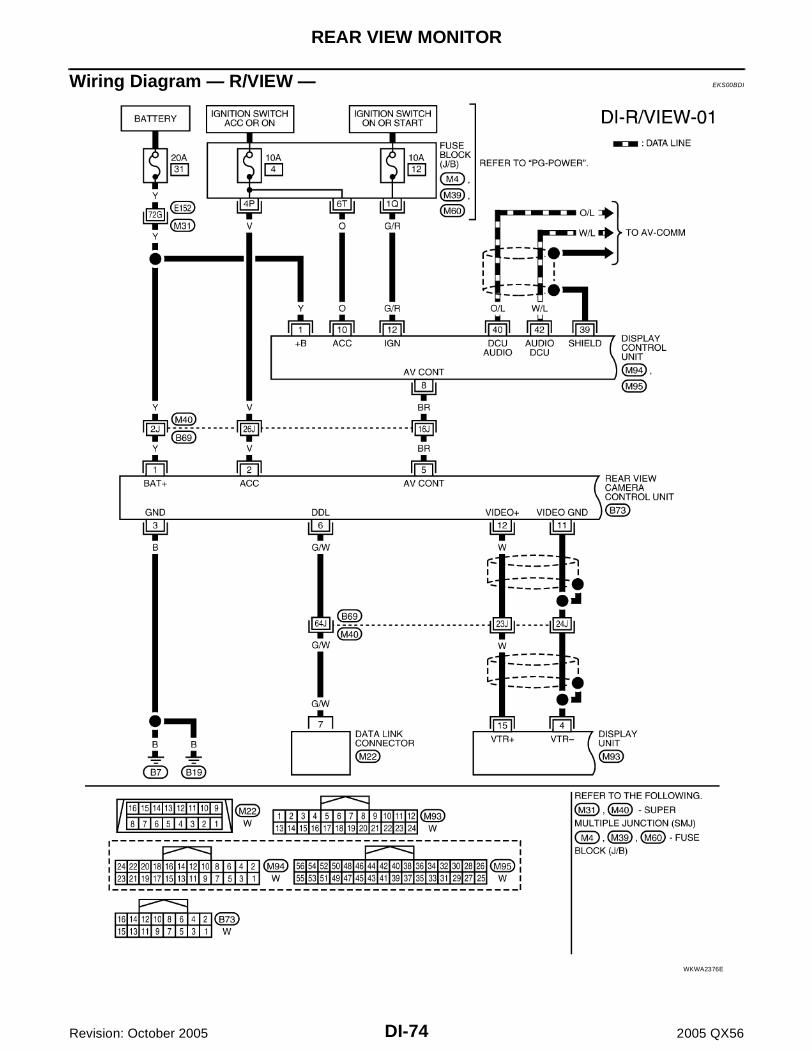
DI-74
REAR VIEW MONITOR
Revision: October 2005 2005 QX56
Wiring Diagram — R/VIEW — EKS00BDI
WKWA2376E

REAR VIEW MONITOR
DI-75
C
D
E
F
G
H
I
J
L
M
A
B
DI
Revision: October 2005 2005 QX56
WKWA2377E

DI-76
REAR VIEW MONITOR
Revision: October 2005 2005 QX56
WKWA1182E
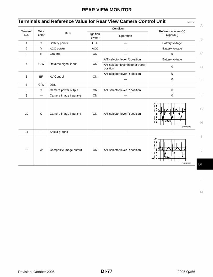
REAR VIEW MONITOR
DI-77
C
D
E
F
G
H
I
J
L
M
A
B
DI
Revision: October 2005 2005 QX56
Terminals and Reference Value for Rear View Camera Control Unit EKS00BDJ
Terminal No.
Wire color
Item
ConditionReference value (V)
(Approx.)Ignition switch
Operation
1 Y Battery power OFF — Battery voltage
2 V ACC power ACC — Battery voltage
3 B Ground ON — 0
4 G/W Reverse signal input ON
A/T selector lever R position Battery voltage
A/T selector lever in other than R position
0
5 BR AV Control ONA/T selector lever R position 0
— 0
6 G/W DDL — — —
8 Y Camera power output ON A/T selector lever R position 6
9 — Camera image input (–) ON — 0
10 G Camera image input (+) ON A/T selector lever R position
11 — Shield ground — — —
12 W Composite image output ON A/T selector lever R position
SKIA4894E
SKIA4896E

DI-78
REAR VIEW MONITOR
Revision: October 2005 2005 QX56
CONSULT-II Function (REARVIEW CAMERA) EKS00BDK
CONSULT-II can display each diagnostic item using the diagnostic test modes shown following.
CONSULT-II BASIC OPERATIONCAUTION:If CONSULT-II is used with no connection of CONSULT-II CONVERTER, malfunctions might bedetected in self-diagnosis depending on control unit which carries out CAN communication.1. With the ignition switch OFF, connect “CONSULT-II” and “CON-
SULT-II CONVERTER” to the data link connector, then turn igni-tion switch ON.
2. Touch “START (NISSAN BASED VHCL)”.
3. Touch “REARVIEW CAMERA” on “SELECT SYSTEM” screen. If"REARVIEW CAMERA” is not indicated, go to BCS-11, "CON-SULT–II INSPECTION PROCEDURE" .
REARVIEW CAMERAdiagnostic mode
Description
WORK SUPPORTSupports inspection and adjustments. Commands are transmitted to the rearview camera control unit for setting the status suitable for required operation, input/output signals are received from the rear-view camera control unit and received data is displayed.
DATA MONITOR Displays rearview camera control unit input/output data in real time.
ECU PART NUMBER Rearview camera control unit part number can be read.
BBIA0369E
BCIA0029E
BCIA0030E

REAR VIEW MONITOR
DI-79
C
D
E
F
G
H
I
J
L
M
A
B
DI
Revision: October 2005 2005 QX56
4. Select “WORK SUPPORT”, “DATA MONITOR” or “ECU PARTNUMBER”.
WORK SUPPORTOperation Procedure1. Touch “WORK SUPPORT” on “SELECT DIAG MODE” screen.2. Touch either “SELCT GUIDELINE PATTERN” or “ADJ GUIDELINE POSITION” on the “SELECT WORK
ITEM” screen.
Refer to DI-80, "SIDE DISTANCE GUIDELINE CORRECTION PROCEDURE" for detail.
DATA MONITOROperation Procedure1. Touch “DATA MONITOR” on “SELECT DIAG MODE” screen.2. Touch either “ALL SIGNALS” or “SELECTION FROM MENU” on the “SELECT MONITOR ITEM” screen.
3. When “SELECTION FROM MENU” is selected, touch individual items to be monitored. When “ALL SIG-NALS” is selected, all items will be monitored.
4. Touch “START”.5. Touch “RECORD” while monitoring, then the status of the monitored item can be recorded. To stop
recording, touch “STOP”.
Display Item List
BCIA0031E
SELCT GUIDELINE PATTERN Side distance guideline is optional from two patterns.
ADJ GUIDELINE POSITION Side distance guideline is adjustable toward up and down, right and left.
ALL SIGNALS Monitors all signals.
SELECTION FROM MENU Selects and monitors individual signal.
Display item [Unit]ALL SIG-
NALSSELECTION FROM MENU
Contents
R POSI SIG [ON/OFF] X X Indicates [ON/OFF] condition of R position signal input.

DI-80
REAR VIEW MONITOR
Revision: October 2005 2005 QX56
Side Distance Guideline Correction EKS00BDL
This mode is used to modify the side distance guidelines if they are dislocated from the rear view monitorimage, because of variations of body/camera mounting conditions.
SIDE DISTANCE GUIDELINE CORRECTION PROCEDURE1. Create a correction line to modify the screen.
Draw lines on the rearward of the vehicle passing through thefollowing points: 200 mm (7.87 inch) from both sides of the vehi-cle, and *1: 0.5 m (1.5 feet) *2: 1 m (3 feet) *3: 2 m (7 feet) *4: 3 m (10 feet)
and from the rear end of the bumper2. With the ignition switch OFF, connect “CONSULT-II” and “CON-
SULT-II CONVERTER” to the data link connector, then turn igni-tion switch ON. Touch “REARVIEW CAMERA” on “SELECTSYSTEM” screen.CAUTION:Stop engine for safety when correcting side distance guide-line.
3. Shift the A/T select lever to R position.
4. Touch “SELCT GUIDELINE PATTERN” on “SELECT WORKITEM” screen.
SKIA5637E
SKIA6103E
SKIA5638E

REAR VIEW MONITOR
DI-81
C
D
E
F
G
H
I
J
L
M
A
B
DI
Revision: October 2005 2005 QX56
5. Touch “UP” or “DOWN”, and select the guide line, “PATTERNNO. 0” or “PATTERN NO. 1”, which is the closest to the cor-rected line.
6. Touch “SAVE”, and confirm the guide line.7. Touch “END”.
8. Touch “ADJ GUIDELINE POSITION” on “SELECT WORKITEM” screen.
9. Adjust the guide line touching “X UP”, “X DOWN”, “Y UP” or “YDOWN” so that the corrected line can fit the guide line.
10. Touch “SAVE”, and confirm the guide line.11. Touch “END” to finish correcting.
SKIA5639E
SKIA5638E
SKIA5642E

DI-82
REAR VIEW MONITOR
Revision: October 2005 2005 QX56
Power Supply and Ground Circuit Inspection EKS00BDM
1. CHECK FUSES
Check for blown rear view camera system fuses.
OK or NGOK >> GO TO 2.NG >> If fuse is blown, be sure to eliminate cause of problem before installing new fuse. Refer to PG-4,
"POWER SUPPLY ROUTING CIRCUIT" .
2. CHECK POWER SUPPLY CIRCUIT
1. Disconnect rear view camera control unit connector. 2. Check voltage between rear view camera control unit and
ground.
OK or NGOK >> GO TO 3.NG >> Check harness for open between rear view camera control unit and fuse.
3. CHECK REAR VIEW CAMERA CONTROL UNIT GROUND CIRCUIT
1. Turn ignition switch OFF.2. Check continuity between rear view camera control unit harness
connector B73 terminal 3 (B) and ground.
OK or NGOK >> GO TO 4.NG >> Repair harness or connector.
4. CHECK REAR VIEW CAMERA GROUND CIRCUIT
1. Disconnect rear view camera connector.2. Check continuity between rear view camera harness connector
D504 terminal 2 (B) and ground.
OK or NGOK >> Inspection End.NG >> Repair harness or connector.
Unit Power source Fuse No.
Rear view camera control unitBattery 31
Ignition switch ACC or ON 4
Terminals
OFF ACC(+)
(–)Connector
Terminal(Wire color)
B731 (Y) Ground Battery voltage Battery voltage
2 (V) Ground 0V Battery voltage WKIA2027E
Continuity should exist.
SKIA5081E
Continuity should exist.
SKIA5082E

REAR VIEW MONITOR
DI-83
C
D
E
F
G
H
I
J
L
M
A
B
DI
Revision: October 2005 2005 QX56
Rear View Is Not Displayed With The A/T Selector Lever In R Position EKS00BDN
1. BACK-UP LAMP INSPECTION
1. Turn ignition switch ON.2. Shift A/T selector lever to R position.Does back-up lamp illuminate?YES >> GO TO 2.NO >> Check back-up lamp system. Refer to LT-106, "BACK-UP LAMP" .
2. CHECK REVERSE POSITION INPUT SIGNAL
With CONSULT-IISelect “DATA MONITOR” of “REARVIEW CAMERA”. Operate igni-tion switch with “R POSI SIG” of “DATA MONITOR” and check oper-ate status.
Without CONSULT-II1. Turn ignition switch OFF.2. Disconnect rear view camera control unit connector.3. Turn ignition switch ON.4. Shift A/T selector lever to R position.5. Check voltage between rear view camera control unit harness
connector B73 terminal 4 (G/W) and ground.
OK or NGOK >> GO TO 3.NG >> Check harness for open or short between rear view
camera control unit and back-up lamp relay.
3. CHECK DISPLAY CONTROL UNIT OUTPUT SIGNAL
1. Turn ignition switch OFF.2. Disconnect rear view camera control unit connector.3. Turn ignition switch ON.4. Check voltage between rear view camera control unit harness
connector B73 terminal 5 (BR) and ground.
OK or NGOK >> GO TO 5.NG >> GO TO 4.
SKIA7147E
Battery voltage should exist.
SKIA5086E
Voltage : Approx. 5V
SKIA7148E

DI-84
REAR VIEW MONITOR
Revision: October 2005 2005 QX56
4. CHECK DISPLAY CONTROL UNIT CIRCUIT
1. Turn ignition switch OFF.2. Disconnect display control unit connector.3. Check continuity between rear view camera control unit harness
connector B73 terminal 5 (BR) and display control unit harnessconnector M94 terminal 8 (BR).
4. Check continuity between rear view camera control unit harnessconnector B73 terminal 5 (BR) and ground.
OK or NGOK >> Replace display control unit. Refer to AV-158, "Removal and Installation of Display Control Unit" .NG >> Repair harness or connector.
5. CHECK AV CONTROL SIGNAL
1. Turn ignition switch OFF.2. Connect rear view camera control unit connector.3. Shift A/T selector lever to R position.4. Check voltage between rear view camera control unit harness
connector B73 terminal 5 (BR) and ground.
OK or NGOK >> GO TO 6.NG >> Replace rear view camera control unit. Refer to DI-87,
"Removal and Installation of Rear View Camera ControlUnit" .
6. CHECK REAR VIEW CAMERA OPEN CIRCUIT
1. Turn ignition switch OFF.2. Disconnect rear view camera connector.3. Check continuity between rear view camera control unit harness
connector B73 terminal 8 (Y) and rear view camera harnessconnector D504 terminal 1 (Y).
4. Check continuity between rear view camera control unit harnessconnector B73 terminal 9 and rear view camera harness con-nector D504 terminal 4.
5. Check continuity between rear view camera control unit harness connector B73 terminal 10 (G) and rearview camera harness connector D504 terminal 3 (G).
OK or NGOK >> GO TO 7.NG >> Repair harness or connector.
Continuity should exist.
Continuity should not exist. SKIA7149E
Voltage : Approx. 0V
SKIA7150E
Continuity should exist.
Continuity should exist.
Continuity should exist.
SKIA5095E

REAR VIEW MONITOR
DI-85
C
D
E
F
G
H
I
J
L
M
A
B
DI
Revision: October 2005 2005 QX56
7. CHECK REAR VIEW CAMERA SHORT CIRCUIT
1. Check continuity between rear view camera control unit harnessconnector B73 terminal 8 (Y) and ground.
2. Check continuity between rear view camera control unit harnessconnector B73 terminal 9 and ground.
3. Check continuity between rear view camera control unit harnessconnector B73 terminal 10 (G) and ground.
OK or NGOK >> GO TO 8.NG >> Repair harness on connector.
8. CHECK POWER SUPPLY AND GROUND CIRCUIT
Check power supply and ground circuit. Refer to DI-82, "Power Supply and Ground Circuit Inspection" .OK or NGOK >> GO TO 9.NG >> Repair or replace power supply or ground circuit.
9. CHECK REAR VIEW CAMERA CONTROL UNIT OUTPUT SIGNAL
1. Connect rear view camera control unit connector.2. Turn ignition switch ON.3. Shift A/T selector lever to R position.4. Check voltage between rear view camera control unit harness
connector B73 terminal 8 (Y) and ground.
OK or NGOK >> GO TO 10.NG >> Replace the rear view camera control unit. Refer to DI-
87, "Removal and Installation of Rear View CameraControl Unit" .
Continuity should not exist.
Continuity should not exist.
Continuity should not exist.
SKIA5098E
Voltage : Approx. 6V
SKIA5099E

DI-86
REAR VIEW MONITOR
Revision: October 2005 2005 QX56
10. CHECK REAR VIEW CAMERA SIGNAL
1. Connect rear view camera connector.2. Turn ignition switch ON.3. Shift A/T selector lever to R position.4. Check voltage signal between rear view camera control unit har-
ness connector B73 terminal 10 (G) and ground.
OK or NGOK >> GO TO 11.NG >> Replace the rear view camera. Refer to DI-87, "Removal and Installation of Rear View Camera" .
11. CHECK COMPOSITE SIGNAL OPEN OR SHORT CIRCUIT
1. Turn ignition switch OFF.2. Disconnect rear view camera control unit connector and display
unit connector.3. Check continuity between rear view camera control unit harness
connector B73 terminal 12 (W) and display unit harness connec-tor M93 terminal 15 (W).
4. Check continuity between rear view camera control unit harnessconnector B73 terminal 12 (W) and ground.
OK or NGOK >> GO TO 12.NG >> Repair harness or connector.
12. CHECK COMPOSITE SIGNAL GROUND CIRCUIT
1. Check continuity between rear view camera control unit harnessconnector B73 terminal 11 and display unit harness connectorM93 terminal 4.
2. Check continuity between rear view camera control unit harnessconnector B73 terminal 11 and ground.
OK or NGOK >> GO TO 13.NG >> Repair harness or connector.
10 (G) - Ground:SKIA5100E
SKIA4894E
Continuity should exist.
Continuity should not exist.WKIA1825E
Continuity should exist.
Continuity should not exist.
WKIA1826E

REAR VIEW MONITOR
DI-87
C
D
E
F
G
H
I
J
L
M
A
B
DI
Revision: October 2005 2005 QX56
13. CHECK REAR VIEW CAMERA CONTROL UNIT COMPOSITE SIGNAL
1. Connect rear view camera control unit connector and displayunit connector.
2. Turn ignition switch ON.3. Check voltage signal between rear view camera control unit har-
ness connector B73 terminal 12 (W) and ground.
OK or NGOK >> Replace the display unit. Refer to AV-158, "Removal and Installation of Display Unit" .NG >> Replace the rear view camera control unit. Refer to DI-87, "Removal and Installation of Rear View
Camera Control Unit" .
Removal and Installation of Rear View Camera Control Unit EKS00BDO
REMOVAL1. Remove luggage side finishers LH. Refer to EI-40, "LUGGAGE
FLOOR TRIM" .2. Remove screws (2) and remove rear view camera control unit.
INSTALLATIONInstallation is in the reverse order of removal.
Removal and Installation of Rear View Camera EKS00BDP
REMOVAL1. Remove back door lower finisher. Refer to EI-42, "BACK DOOR TRIM" .2. Remove connector.3. Remove screws (2) and remove rear view camera.
INSTALLATIONInstallation is in the reverse order of removal.
12 (W) - Ground:WKIA1827E
SKIA4896E
LKIA0478E
LKIA0479E
DI-88
REAR VIEW MONITOR
Revision: October 2005 2005 QX56