k-1700-ip product manual - phone-master · product manual designed, manufactured and supported in...
TRANSCRIPT

PRODUCT MANUALDesigned, Manufactured and Supported in the USA
S E C U R I T Y & C O M M U N I C AT I O N S O L U T I O N S
VIKING
Features
Applications Specifications
Information: 715-386-8861www.vikingelectronics.com
• Vandal Resistant Features: 14 gauge louvered 316 stainless steel faceplatewith permanent laser etched graphics. Speaker/mic screen. Heavy duty metalkeypad and “Call” button. Scratch resistant powder coating (K-1700-BN-IP).T-10 Security Torx drive mounting screws.
• Weather Resistant Features: Marine grade 316 stainless steel faceplate,screws and push button switch. Switch internally sealed per IP67. Mylarspeaker. Self-draining mic mount. Faceplate, mic and speaker gaskets.Weather resistant powder paint (K-1700-BN-IP)
• Available in 2 standard finishes: 316 brushed stainless steel with laser etchedgraphics or oil rubbed bronze powder paint with copper metallic graphics
• Two sets of SPDT 2 Amp relay contacts for door/gate or camera control • Optional RC-4A for Secure Remote Relay Control, see DOD# 582• Blue “Call /Status” LED indicator • SIP compliant (see pg 2 for list of compatible IP-PBX phone systems)• PoE powered (class 2, <6.5 watts)• Automatic Noise Canceling (ANC) feature for operation in noisy environments• Viking’s proprietary VOX switching eliminates the need for “Push to Talk” mode• Network downloadable firmware
Power: PoE class 2 (<6.5 watts)Dimensions: Overall: 5.5” x 6.5” x 2.6” (140mm x 165mm x 66mm)
Rough-in box: 4.5” x 5.5” x 2.5” (114mm x 140mm x 64mm)Shipping Weight: 1.5 kg (3.2 lbs) Operating Temperature: -40°F to 140°F (-40° C to 60° C)Humidity - Standard Products: 5% to 95% non-condensingHumidity - EWP Products: Up to 100%Audio Codecs: G711u, G711a, G722Network Compliance: IEEE 802.3 af PoE, SIP 2.0 RFC3261, 100BASE-TX withauto cross overConnections: (1) RJ45 10/100 Base-T, (14) gel-filled butt connectors
Installation requires the assistance of a Network Administrator / IT Technician.!
The K-1700-IP Series entry phones provide a durable and attractive hands-free phone forapartment and residential door entry or applications requiring a vandal resistant VoIPspeaker phone. The K-1700-IP phone is designed to provide quick and reliable hands-freecommunication for SIP VoIP phone systems with PoE. The unit can be programmed fromany PC on the same LAN or remotely using a Static IP Address. The K-1700-IP entry phonecan dial up to 250 programmable numbers and another 250 rollover numbers. They areavailable in two attractive finishes: “Brushed Stainless Steel” and “Oil Rubbed Bronze”.
When the K-1700-IP phone is connected to an apartment or business tenant, a built-incontact closure may be activated to control an electric gate or door strike. Up to 1,000keyless entry codes may be programmed, providing tenants with keyless entry. A 26 BitWiegand input is provided for adding an optional proximity card reader with capacity toprogram up to 1,000 card numbers. Keyless entry codes and card numbers can beprogrammed to only allow access at specific times and/or day of the week. The K-1700-IPincludes a request for exit (REX) input and also offers activity logging.
• Apartment Entry Phone
• Residential Gate Entrance
• Door Entry Phone
• Courtesy Assistance Phone
• Customer Service Phone
• Automated Teller (ATM) Phone
K-1700-IP “Brushed 316 Stainless Steel”
(similar to brushed nickel)
(shown in optional surface mount box)
K-1700-BN-IP“Oil Rubbed Bronze”
(satin dark brown powder paint
with fine copper metallic)
The K-1700-IP-EWP shares all of the features of the K-1700-IP in additionto Enhanced Weather Protection (EWP) for outdoor installations wherethe unit is exposed to precipitation or condensation. EWP products featurefoam rubber gaskets and boots, sealed connections, gel-filled buttconnectors, as well as urethane or thermal plastic potted circuit boards.For more information on EWP, see DOD# 859.
• 26 Bit Wiegand input for optional proximity card readers, see DOD# 221 & 228• Programmable to speed dial up to 250 numbers • Cycles to roll over phone number on busy or no-answer• Program up to 1,000 keyless entry codes and/or proximity card numbers • Keyless entry codes and proximity card numbers can be programmed to only
allow access at specific times and day of week • Event logging with time and date stamp• Optional Enhanced Weather Protection (EWP), EWP products are designed to
meet IP66 Ingress Protection Rating, see DOD# 859• Hangs up on busy signal, time-out or touch tone command• Remotely programmable • Extended temperature range (-40°F to 140°F)• Programmable volume adjustments for microphone and speaker• Selectable auto-answer feature for monitoring• Zinc plated steel rough-in box included• Optional VE-6x7 Surface Mount Box available, see DOD #424• Optional VE-LIGHT kit to illuminate the front panel at night, see DOD# 428• Self diagnostics (testing: com, mic, speaker, and switch)
• Security or Emergency
Phone
• Hot-Line Phone
• Kiosk Phone with up to
250 number speed dialing
K-1700-IP SeriesVoIP Entry Phone System
with Built-In KeypadJuly 11, 2016
Vandal Resistant VoIP Entry Phone Systemwith Integrated Keypad
2
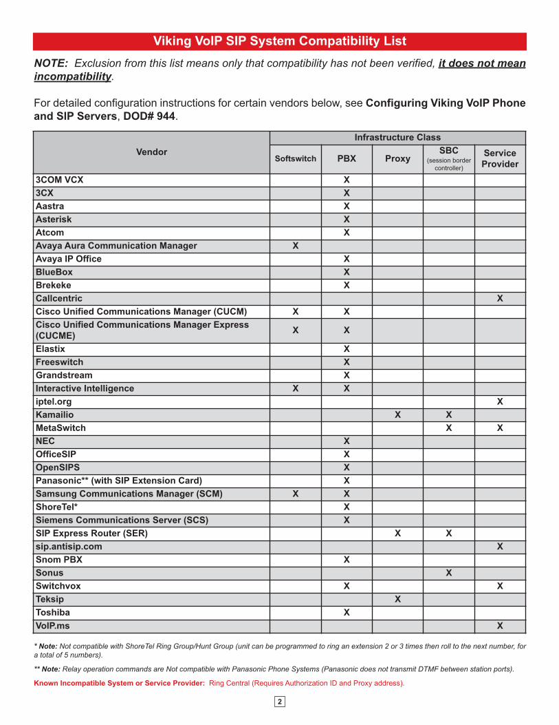
Viking VoIP SIP System Compatibility List
NOTE: Exclusion from this list means only that compatibility has not been verified, it does not meanincompatibility.
For detailed configuration instructions for certain vendors below, see Configuring Viking VoIP Phone
and SIP Servers, DOD# 944.
* Note: Not compatible with ShoreTel Ring Group/Hunt Group (unit can be programmed to ring an extension 2 or 3 times then roll to the next number, fora total of 5 numbers).
** Note: Relay operation commands are Not compatible with Panasonic Phone Systems (Panasonic does not transmit DTMF between station ports).
Known Incompatible System or Service Provider: Ring Central (Requires Authorization ID and Proxy address).
Vendor
Infrastructure Class
Softswitch PBX ProxySBC
(session border
controller)
Service
Provider
3COM VCX X
3CX X
Aastra X
Asterisk X
Atcom X
Avaya Aura Communication Manager X
Avaya IP Office X
BlueBox X
Brekeke X
Callcentric X
Cisco Unified Communications Manager (CUCM) X X
Cisco Unified Communications Manager Express
(CUCME)X X
Elastix X
Freeswitch X
Grandstream X
Interactive Intelligence X X
iptel.org X
Kamailio X X
MetaSwitch X X
NEC X
OfficeSIP X
OpenSIPS X
Panasonic** (with SIP Extension Card) X
Samsung Communications Manager (SCM) X X
ShoreTel* X
Siemens Communications Server (SCS) X
SIP Express Router (SER) X X
sip.antisip.com X
Snom PBX X
Sonus X
Switchvox X X
Teksip X
Toshiba X
VoIP.ms X
3
Definitions
Client: A computer or device that makes use of a server. As an example, the client might request a particular file from the server.
DHCP: Dynamic Host Configuration Protocol. In this procedure the network server or router takes note of a client’s MAC address and
assigns an IP address to allow the client to communicate with other devices on the network.
DNS Server: A DNS (Domain Name System) server translates domain names (ie: www.vikingelectronics.com) into an IP address.
Ethernet: Ethernet is the most commonly used LAN technology. An Ethernet Local Area Network typically uses twisted pair wires to
achieve transmission speeds up to 1Gbps.
Host: A computer or device connected to a network.
Host Name: A host name is a label assigned to a device connected to a computer network that is used to identify the device in various
forms of network communication.
Hosts File: A file stored in a computer that lists host names and their corresponding IP addresses with the purpose of mapping addresses
to hosts or vice versa.
Internet: A worldwide system of computer networks running on IP protocol which can be accessed by individual computers or networks.
IP: Internet Protocol is the set of communications conventions that govern the way computers communicate on networks and on the
Internet.
IP Address: This is the address that uniquely identifies a host on a network.
LAN: Local Area Network. A LAN is a network connecting computers and other devices within an office or building.
Lease: The amount of time a DHCP server reserves an address it has assigned. If the address isn’t used by the host for a period of
time, the lease can expire and the address can be assigned to another host.
MAC Address: MAC stands for Media Access Control. A MAC address, also called a hardware address or physical address, is a unique
address assigned to a device at the factory. It resides in the device’s memory and is used by routers to send network traffic to the correct
IP address. You can find the MAC address of your K-1700-IP phone printed on a white label on the top surface of the PoE LAN port.
Router: A device that forwards data from one network to another. In order to send information to the right location, routers look at IP
Address, MAC Address and Subnet Mask.
RTP: Real-Time Transport Protocol is an Internet protocol standard that specifies a way for programs to manage the real-time transmission
of multimedia data over either unicast or multicast network services.
Server: A computer or device that fulfills requests from a client. This could involve the server sending a particular file requested by the
client.
Session Initiation Protocol (SIP): Is a signaling communications protocol, widely used for controlling multimedia communication sessions
such as voice and video calls over Internet Protocol (IP) networks. The protocol defines the messages that are sent between endpoints,
which govern establishment, termination and other essential elements of a call.
Static IP Address: A static IP Address has been assigned manually and is permanent until it is manually removed. It is not subject to the
Lease limitations of a Dynamic IP Address assigned by the DHCP Server. The default static IP Address is: 192.168.154.1
Subnet: A portion of a network that shares a common address component. On TCP/IP networks, subnets are defined as all devices
whose IP addresses have the same prefix. For example, all devices with IP addresses that start with 100.100.100. would be part of the
same subnet. Dividing a network into subnets is useful for both security and performance reasons. IP networks are divided using a subnet
mask.
TCP/IP: Transmission Control Protocol/Internet Protocol is the suite of communications protocols used to connect hosts on the Internet.
TCP/IP uses several protocols, the two main ones being TCP and IP. TCP/IP is built into the UNIX operating system and is used by the
Internet, making it the de facto standard for transmitting data over networks.
TISP: Telephone Internet Service Provider
WAN: Wide Area Network. A WAN is a network comprising a large geographical area like a state or country. The largest WAN is the
Internet.
Wireless Access Point (AP): A device that allows wireless devices to connect to a wired network using Wi-Fi, or related standards. The
AP usually connects to a router (via a wired network) as a standalone device, but it can also be an integral component of the router itself.
Wireless Repeater (Wireless Range Extender): takes an existing signal from a wireless router or access point and rebroadcasts it to
create a second network. When two or more hosts have to be connected with one another over the IEEE 802.11 protocol and the distance
is too long for a direct connection to be established, a wireless repeater is used to bridge the gap.
4
Features Overview
MA
C:
18E80FXXXXXX
asdesaxtff
N.C.
- Black+ Red
- Black+ Red
Green
Green Green
White
N.O.COM.
N.C. (Gray)
N.O. (Yellow)
COM. (Blue)
Relay 1Output Contacts
(2A@30VDC/ 250VAC max)
Relay 2 Output Contacts(2A@30VDC/ 250VAC max)
Request for Exit (REX) Input
* 3 Gel-Filled ButtConnectors (included)
+ Red
- Black
Black
Black
- Black
+ Red
Speaker
LED
Microphone
Call Switch
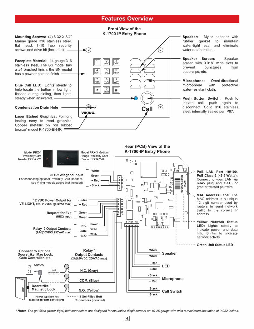
MAC Address Label: The MAC address is a unique 12 digit number used by routers to send network traffic to the correct IP address.
PoE LAN Port 10/100, PoE Class 2 (<6.5 Watts): Connect to your LAN via RJ45 plug and CAT5 or greater twisted pair wire.
Yellow Network Status LED: Lights steady to indicate power and data link. Blinks to indicate network activity.
Green Unit Status LED
Rear (PCB) View of theK-1700-IP Entry Phone
White
White
(Power typically notrequired for gate controllers)
Doorstrike / Magnetic Lock
120V AC
Connect to Optional Doorstrike, Mag Lock, Gate Controller, etc.
(notconnected)
26 Bit Wiegand InputFor connecting optional Proximity Card Readers,
see Viking models above (not included)
12 VDC Power Output for VE-LIGHT, etc. (12VDC @ 50mA max)
Brown
Violet
White
Model PRX-1 Proximity Card
Reader DOD# 221
Model PRX-3 Medium Range Proximity Card Reader DOD# 228
* Note: The gel-filled (water-tight) butt connectors are designed for insulation displacement on 19-26 gauge wire with a maximum insulation of 0.082 inches.
Push Button Switch: Push to initiate call, push again to disconnect. Solid 316 stainless steel, internally sealed per IP67.
Speaker Screen: Speaker screen with 0.018" wide slots to prevent punctures from paperclips, etc.
Faceplate Material: 14 gauge 316 stainless steel. The SS model has a #4 brushed finish, the BN model has a powder painted finish.
Speaker: Mylar speaker with rubber gasket to maintain water-tight seal and eliminate water deterioration.
Blue Call LED: Lights steady to help locate the button in low light, flashes during dialing, then lights steady when answered.
Microphone: Omni-directional microphone with protective water-resistant cloth.
Front View of theK-1700-IP Entry Phone
CallVIKING©
Condensation Drain Hole
Mounting Screws: (4) 6-32 X 3/4” Marine grade 316 stainless steel, flat head, T-10 Torx security screws and drive bit (included).
Laser Etched Graphics: For long lasting easy to read graphics. Copper metallic on “oil rubbed bronze” model K-1700-BN-IP.
1 2ABC
5JKL
8TUV
0OPER
4GHI
7PRS
#
3DEF
6MNO
9WXY

5
Installation and Mounting
Applications / Wiring
(1) .74”
diameter
Rear View of the
Optional VE-6x7
Surface Mount Box
3.0”3.3”
3.0”
2.25”
Condensation
Drain Hole
5.64”
6.72” 3.25”
(2) 0.2 x 0.43 slots
(4) 0.38” diameter
4.5”
2.5”
3/4” ConduitKnockouts
5.5”
Rough-In
Box
(included)
1
2ABC
3DEF
4GHI
5JKL
6MNO
7PRS
8TUV
9WXY
0OPER
#
Call
VIKING©
12
ABC
3DEF
4GHI
5JKL
6MNO
7PRS
8TUV
9WXY
0OPER
#
Mounting Screws: (4) 6-32 X 3/4”
Marine grade 316 stainless steel,
flat head, T-10 Torx security
screws and drive bit (included)
OR
Optional VE-6x7
Surface Mount Box
(not included)
The optional VE-6x7 Surface Mount Box (above) is
designed to be surface mounted to a single gang
box, double gang box, or VE-GNP Gooseneck
Pedestal (shown right). For more information on the
VE-6x7 and VE-GNP, see DOD# 424.
K-1700-IP-EWP
shown with VE-6x7
Surface Mount Box
and VE-GNP
Gooseneck Pedestal
(not included)
Peel paper liner and adhere gasket to back of
panel, centering over mounting holes.
Caution: For rough surfaces (ie: brick, stucco, etc.) additional caulking may be required.
BlackGreenWhite
BlackGreenWhite
(-) (+)
To Wiegand Input on
K-1700-IP
Connect to “-/Ground” on Entry System/Controller and Earth GND
Keep unused leads from shorting
Connect power supply wires to PRX-3 power supply wires and negative lead of the controller
*NOTE: Included with PRX-3
*12V DC Adapter*2200μF Bi Polar Capacitor,
(not polarity sensitive)
*3 Position Butt Connectors
2 Position Butt Connectors (included)
To Relay 2 output contacts
on K-1700-IP
COM.
N.O.White
Violet
When using the PRX-3 with any Viking Entry System/Controller, the provided 12V DC 500mA power adapter and 2200µF bi polar capacitor should
be used.
When mounting a PRX-3 in close proximity of the K-1700-IP ( I.E. using a PRX-3-MK-GNP mounting Kit) In programming set “Relay2 mode” to “Alarm” and wire as shown below. For more Information on PRX-3 See DOD# 228.
IMPORTANT: Electronic devices are susceptible to lightning and power station electrical surges from both the AC outlet and the telephoneline. It is recommended that a surge protector be installed to protect against such surges.
K-1700-IP-EWP shownwith VE-6x7, VE-GNPpedestal, PRX-3-MK-VEGNP mounting kitand PRX-3 CardReader
A. Adding a Viking Model PRX-3 Medium Range Proximity Card Reader

6
Switch
SIP VoIP PBX, SIP Cloud based Service Provider
orPC with SIP
Server Software
Internet
PoESwitch
LED 8LED 7LED 6
LED 4
LED 3LED 2LED 1 LED 5
LED 9
1 2 3
on
4
1 2 3 4
VIKINGELECTRONICS
HUDSON, WI 54016
NETWORK ENABLEDRELAY CONTROLLER
MODEL RC-4A©VIKING
1IN1 C IN2 IN3 C IN4
2 3 4 5 6POW
ER 1
2V D
C
RELAY 1 RELAY 2 RELAY 3 RELAY 4
1 2 3 4 5 7 8 9 10 11 12
STATUSLED
6 NETWORK
LOGIC LEVELPROGRAMMINGRESTORE DEFAULTSSPARE
12V DC Adapter(included)
SensorExamples:
Door Sensor
Gate Sensor
Door Sensor
Door Sensor
N.O.
COM.
Connect to Doorstrike,Mag Lock, Gate Controller, etc.
2 Gel-Filled ButtConnectors (included)
Doorstrike / Magnetic Lock
120V AC
Door / Gate Examples:
Door near Entry Phone 1
N.O.
COM.
2 Gel-Filled ButtConnectors (included)
(Power typically notrequired for gate controllers)
Gate Controller
K-1700-IPEntry Phone 1
K-1700-IPEntry Phone 2
K-1700-IPEntry Phone 3
K-1700-IPEntry Phone 4
Relay 2 Output Contacts (5A@30VDC / 250VAC max)Connect to Gate Controller, etc.
Gate near Entry Phone 1
N.O.
COM.
2 Gel-Filled ButtConnectors (included)
Doorstrike / Magnetic Lock
120V AC
Door near Entry Phone 2
N.O.
COM.
Relay 4 Output Contacts (5A@30VDC / 250VAC max) Connect to Doorstrike,
Mag Lock, Gate Controller, etc.
2 Gel-Filled ButtConnectors (included)
Doorstrike / Magnetic Lock
120V AC
Door near Entry Phone 3
1IN1 C IN2 IN3 C IN4
2 3 4 5 6
Relay 1 Output Contacts (5A@30VDC / 250VAC max)
Connect to Doorstrike,Mag Lock, Gate Controller, etc.
Relay 3 Output Contacts (5A@30VDC / 250VAC max)
The front panel of the K-1700-IP is mounted using security Torx screws to help prevent intruders from removing the panel
and accessing the on board door strike/gate control relays. For applications requiring additional security, a Viking model
RC-4A remote relay controller can be used. The relay controller is mounted securely inside the building and connected to
the same LAN as the K-1700-IP. The on board door strike relays would not be used in this case as the K-1700-IP will send
an encrypted message to the RC-4A to activate its relays which control the door strikes/gates.
Up to 4 K-1700-IP’s can communicate with one RC-4A allowing you to securely control four entrances.
When using an RC-4A for remote relay control the K-1700-IP’s relays should be set to “External” in the PC programming.
Note: If the K-1700-IP loses communications with the RC-4A, the LED on the front panel of the K-1700-IP will flash 3 timesevery 2 seconds indicating the communication error. If this error occurs, make sure the RC-4A is powered, has a networkconnection and has the correct IP address and security code of the K-1700-IP displaying errors.
B. Using a Viking Model RC-4A For Secure Remote Relay Control
7
• IBM compatible personal computer with:
Windows 2000 (service pack 4 or higher)
Windows XP (service pack 2 or higher)
Windows Vista (SP2 or newer), 32 or 64 bit versions
Windows 7
Windows 8
Windows 10
PC Requirements
PC Programming
A DVD is included with each K-1700-IP VoIP Entry Phone. The DVD contains the application “K-1700-IP Tech Tool” used
to program the unit using a PC running Windows 2000, XP, Vista, Windows 7, Windows 8 or Windows 10 (see System
Requirements above). The PC must be connected to the same LAN as the K-1700-IP VoIP phone. Install the application on
your PC by placing the DVD into your PC’s drive. Click “I Accept” on the bottom of the first screen, then select “Viking K-
1700-IP Tech Tool” and click the “Install” button. Follow the directions on the screen. To start the Viking K-1700-IP Tech Tool
application, click on the Viking K-1700-IP Tech Tool icon on your desk top. The Main screen will appear, allowing the user to
program any K-1700-IP phone connected to that LAN.
A. Manually Muting SIP/Network Failure Alarm Beeps (3 beeps repeated every 30 seconds)
With the unit connected and powered (Green LED on and Yellow LED off or blinking) it will output 3 beeps every 30
seconds and turn the Call/Call Connected LED on and off once per second to indicate a SIP registration failure, failure
to receive an echo reply from pinged gateway or Ethernet connection failure. You can manually disable the beeps by
pressing and holding the Call button for 5 seconds (2 beeps will then be heard) or by clicking the “Mute Alarm Until
Next Failure” button in the Viking VoIP programming software. The LED will continue to flash allowing you to trouble
shoot the failure.
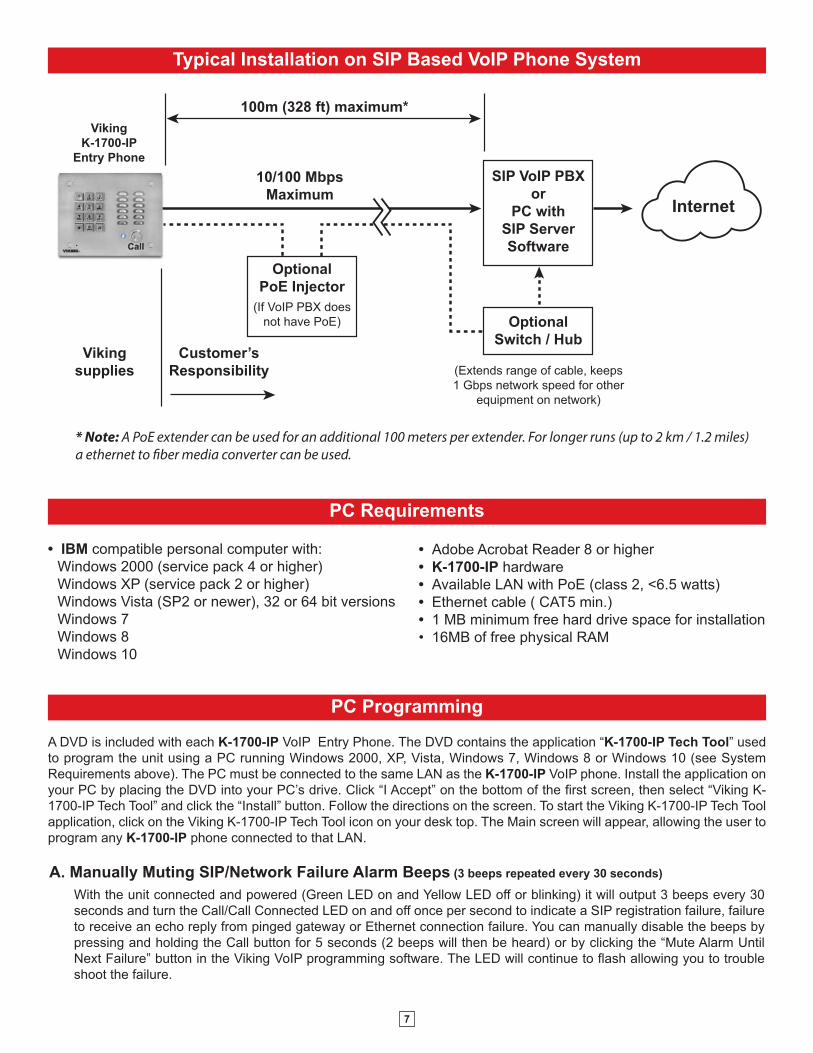
Typical Installation on SIP Based VoIP Phone System
(Extends range of cable, keeps 1 Gbps network speed for other
equipment on network)
SIP VoIP PBXor
PC withSIP ServerSoftware
100m (328 ft) maximum*
Viking supplies
Customer’s Responsibility
Internet
10/100 MbpsMaximum
VikingK-1700-IP
Entry Phone
* Note: A PoE extender can be used for an additional 100 meters per extender. For longer runs (up to 2 km / 1.2 miles) a ethernet to fiber media converter can be used.
OptionalPoE Injector
(If VoIP PBX does not have PoE) Optional
Switch / Hub
• Adobe Acrobat Reader 8 or higher
• K-1700-IP hardware
• Available LAN with PoE (class 2, <6.5 watts)
• Ethernet cable ( CAT5 min.)
• 1 MB minimum free hard drive space for installation
• 16MB of free physical RAM
8
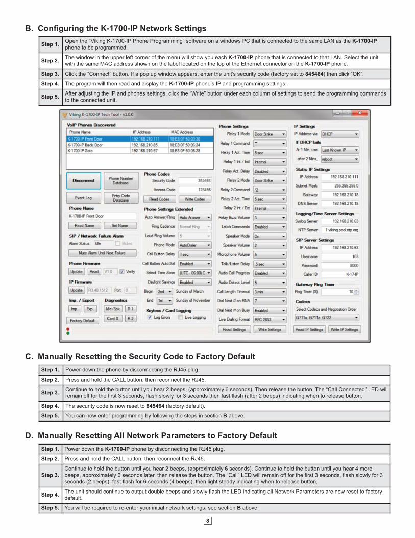
B. Configuring the K-1700-IP Network Settings
Step 1.Open the “Viking K-1700-IP Phone Programming” software on a windows PC that is connected to the same LAN as the K-1700-IP
phone to be programmed.
Step 2.The window in the upper left corner of the menu will show you each K-1700-IP phone that is connected to that LAN. Select the unit
with the same MAC address shown on the label located on the top of the Ethernet connector on the K-1700-IP phone.
Step 3. Click the “Connect” button. If a pop up window appears, enter the unit’s security code (factory set to 845464) then click “OK”.
Step 4. The program will then read and display the K-1700-IP phone’s IP and programming settings.
Step 5.After adjusting the IP and phones settings, click the “Write” button under each column of settings to send the programming commands
to the connected unit.
D. Manually Resetting All Network Parameters to Factory Default
Step 1. Power down the K-1700-IP phone by disconnecting the RJ45 plug.
Step 2. Press and hold the CALL button, then reconnect the RJ45.
Step 3.
Continue to hold the button until you hear 2 beeps, (approximately 6 seconds). Continue to hold the button until you hear 4 more
beeps, approximately 6 seconds later, then release the button. The “Call” LED will remain off for the first 3 seconds, flash slowly for 3
seconds (2 beeps), fast flash for 6 seconds (4 beeps), then light steady indicating when to release button.
Step 4.The unit should continue to output double beeps and slowly flash the LED indicating all Network Parameters are now reset to factory
default.
Step 5. You will be required to re-enter your initial network settings, see section B above.
Step 1. Power down the phone by disconnecting the RJ45 plug.
Step 2. Press and hold the CALL button, then reconnect the RJ45.
Step 3.Continue to hold the button until you hear 2 beeps, (approximately 6 seconds). Then release the button. The “Call Connected” LED will
remain off for the first 3 seconds, flash slowly for 3 seconds then fast flash (after 2 beeps) indicating when to release button.
Step 4. The security code is now reset to 845464 (factory default).
Step 5. You can now enter programming by following the steps in section B above.
C. Manually Resetting the Security Code to Factory Default
9
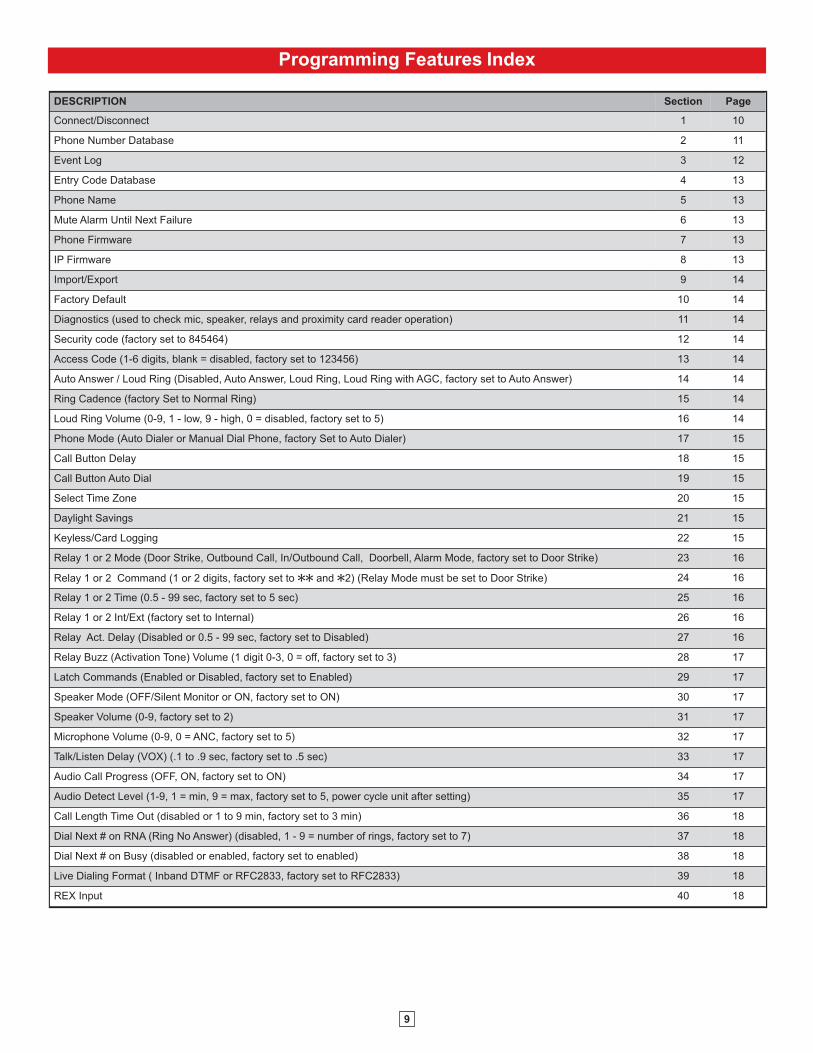
Programming Features Index
DESCRIPTION Section Page
Connect/Disconnect 1 10
Phone Number Database 2 11
Event Log 3 12
Entry Code Database 4 13
Phone Name 5 13
Mute Alarm Until Next Failure 6 13
Phone Firmware 7 13
IP Firmware 8 13
Import/Export 9 14
Factory Default 10 14
Diagnostics (used to check mic, speaker, relays and proximity card reader operation) 11 14
Security code (factory set to 845464) 12 14
Access Code (1-6 digits, blank = disabled, factory set to 123456) 13 14
Auto Answer / Loud Ring (Disabled, Auto Answer, Loud Ring, Loud Ring with AGC, factory set to Auto Answer) 14 14
Ring Cadence (factory Set to Normal Ring) 15 14
Loud Ring Volume (0-9, 1 - low, 9 - high, 0 = disabled, factory set to 5) 16 14
Phone Mode (Auto Dialer or Manual Dial Phone, factory Set to Auto Dialer) 17 15
Call Button Delay 18 15
Call Button Auto Dial 19 15
Select Time Zone 20 15
Daylight Savings 21 15
Keyless/Card Logging 22 15
Relay 1 or 2 Mode (Door Strike, Outbound Call, In/Outbound Call, Doorbell, Alarm Mode, factory set to Door Strike) 23 16
Relay 1 or 2 Command (1 or 2 digits, factory set to QQ and Q2) (Relay Mode must be set to Door Strike) 24 16
Relay 1 or 2 Time (0.5 - 99 sec, factory set to 5 sec) 25 16
Relay 1 or 2 Int/Ext (factory set to Internal) 26 16
Relay Act. Delay (Disabled or 0.5 - 99 sec, factory set to Disabled) 27 16
Relay Buzz (Activation Tone) Volume (1 digit 0-3, 0 = off, factory set to 3) 28 17
Latch Commands (Enabled or Disabled, factory set to Enabled) 29 17
Speaker Mode (OFF/Silent Monitor or ON, factory set to ON) 30 17
Speaker Volume (0-9, factory set to 2) 31 17
Microphone Volume (0-9, 0 = ANC, factory set to 5) 32 17
Talk/Listen Delay (VOX) (.1 to .9 sec, factory set to .5 sec) 33 17
Audio Call Progress (OFF, ON, factory set to ON) 34 17
Audio Detect Level (1-9, 1 = min, 9 = max, factory set to 5, power cycle unit after setting) 35 17
Call Length Time Out (disabled or 1 to 9 min, factory set to 3 min) 36 18
Dial Next # on RNA (Ring No Answer) (disabled, 1 - 9 = number of rings, factory set to 7) 37 18
Dial Next # on Busy (disabled or enabled, factory set to enabled) 38 18
Live Dialing Format ( Inband DTMF or RFC2833, factory set to RFC2833) 39 18
REX Input 40 18
10
Programming Features
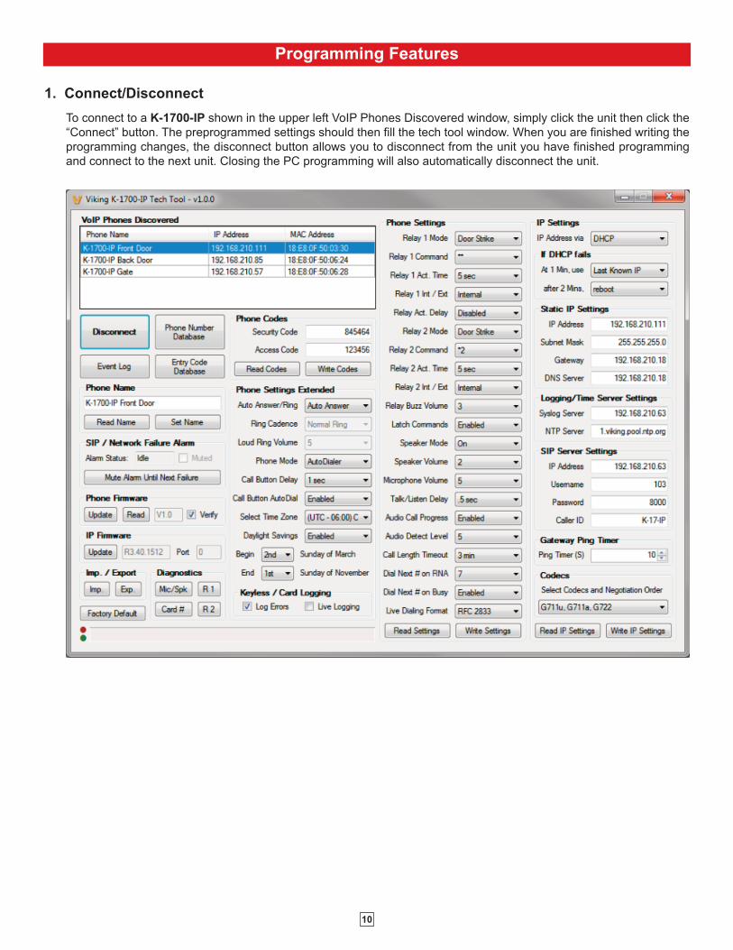
1. Connect/Disconnect
To connect to a K-1700-IP shown in the upper left VoIP Phones Discovered window, simply click the unit then click the
“Connect” button. The preprogrammed settings should then fill the tech tool window. When you are finished writing the
programming changes, the disconnect button allows you to disconnect from the unit you have finished programming
and connect to the next unit. Closing the PC programming will also automatically disconnect the unit.
11
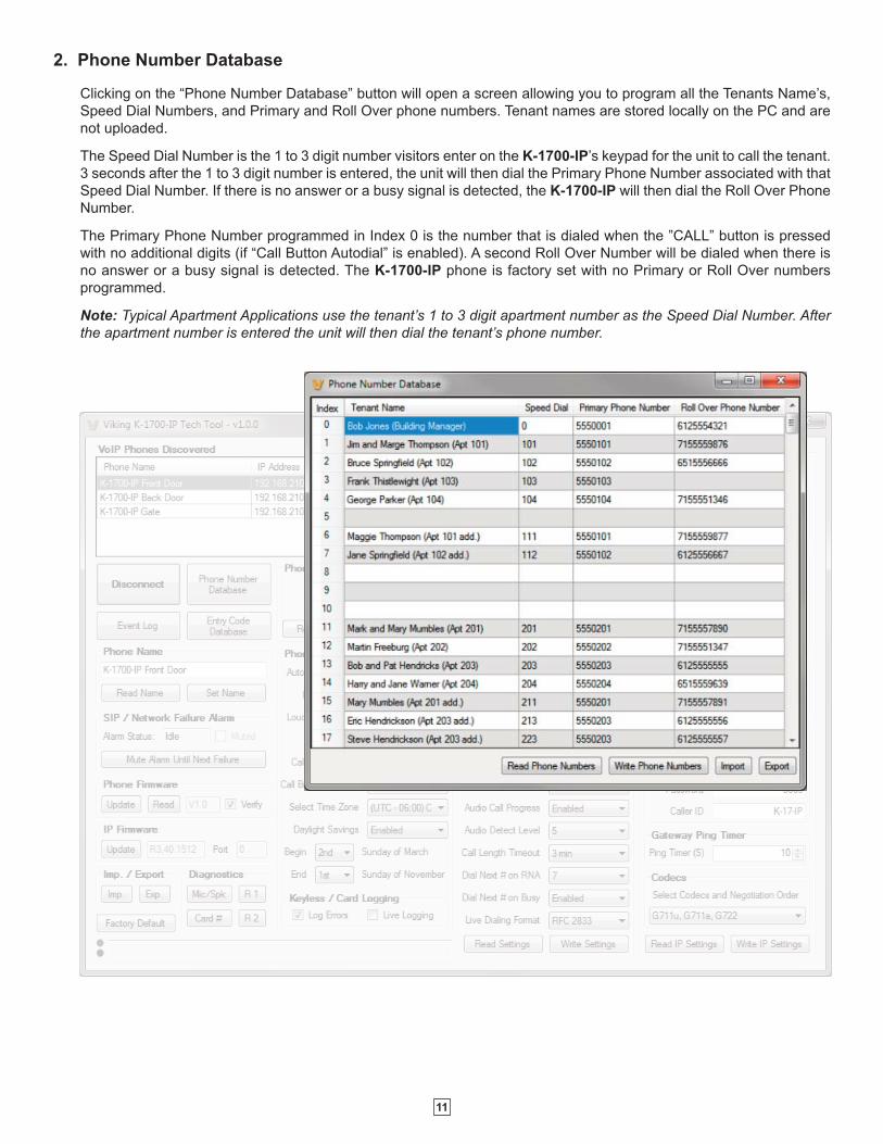
2. Phone Number Database
Clicking on the “Phone Number Database” button will open a screen allowing you to program all the Tenants Name’s,
Speed Dial Numbers, and Primary and Roll Over phone numbers. Tenant names are stored locally on the PC and are
not uploaded.
The Speed Dial Number is the 1 to 3 digit number visitors enter on the K-1700-IP’s keypad for the unit to call the tenant.
3 seconds after the 1 to 3 digit number is entered, the unit will then dial the Primary Phone Number associated with that
Speed Dial Number. If there is no answer or a busy signal is detected, the K-1700-IP will then dial the Roll Over Phone
Number.
The Primary Phone Number programmed in Index 0 is the number that is dialed when the ”CALL” button is pressed
with no additional digits (if “Call Button Autodial” is enabled). A second Roll Over Number will be dialed when there is
no answer or a busy signal is detected. The K-1700-IP phone is factory set with no Primary or Roll Over numbers
programmed.
Note: Typical Apartment Applications use the tenant’s 1 to 3 digit apartment number as the Speed Dial Number. Afterthe apartment number is entered the unit will then dial the tenant’s phone number.
12
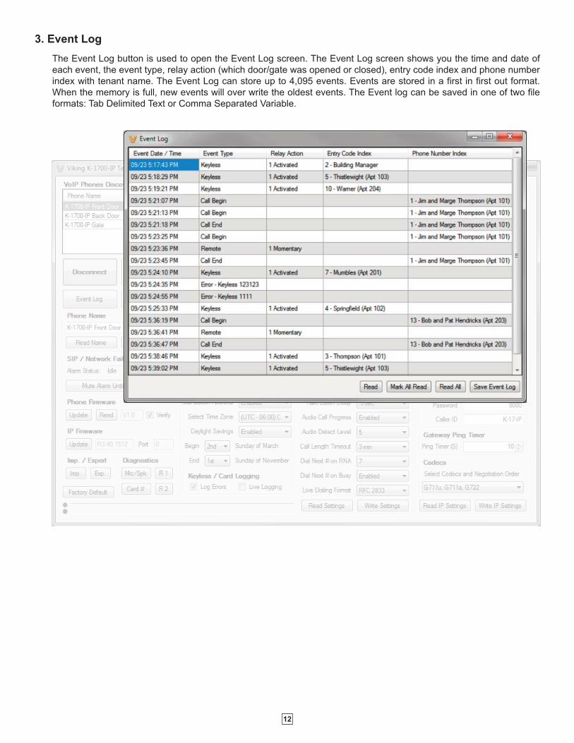
3. Event Log
The Event Log button is used to open the Event Log screen. The Event Log screen shows you the time and date of
each event, the event type, relay action (which door/gate was opened or closed), entry code index and phone number
index with tenant name. The Event Log can store up to 4,095 events. Events are stored in a first in first out format.
When the memory is full, new events will over write the oldest events. The Event log can be saved in one of two file
formats: Tab Delimited Text or Comma Separated Variable.
13
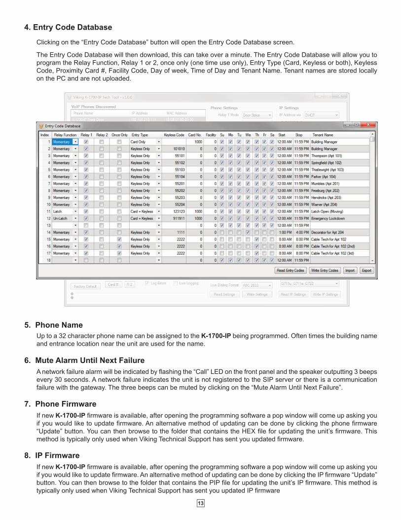
4. Entry Code Database
Clicking on the “Entry Code Database” button will open the Entry Code Database screen.
The Entry Code Database will then download, this can take over a minute. The Entry Code Database will allow you to
program the Relay Function, Relay 1 or 2, once only (one time use only), Entry Type (Card, Keyless or both), Keyless
Code, Proximity Card #, Facility Code, Day of week, Time of Day and Tenant Name. Tenant names are stored locally
on the PC and are not uploaded.
5. Phone Name
6. Mute Alarm Until Next Failure
7. Phone Firmware
8. IP Firmware
Up to a 32 character phone name can be assigned to the K-1700-IP being programmed. Often times the building name
and entrance location near the unit are used for the name.
A network failure alarm will be indicated by flashing the “Call” LED on the front panel and the speaker outputting 3 beeps
every 30 seconds. A network failure indicates the unit is not registered to the SIP server or there is a communication
failure with the gateway. The three beeps can be muted by clicking on the “Mute Alarm Until Next Failure”.
If new K-1700-IP firmware is available, after opening the programming software a pop window will come up asking you
if you would like to update firmware. An alternative method of updating can be done by clicking the phone firmware
“Update” button. You can then browse to the folder that contains the HEX file for updating the unit’s firmware. This
method is typically only used when Viking Technical Support has sent you updated firmware.
If new K-1700-IP firmware is available, after opening the programming software a pop window will come up asking you
if you would like to update firmware. An alternative method of updating can be done by clicking the IP firmware “Update”
button. You can then browse to the folder that contains the PIP file for updating the unit’s IP firmware. This method is
typically only used when Viking Technical Support has sent you updated IP firmware
14
9. Import/Export
The Import/Export feature is useful for backing up all the K-1700-IP’s programming or for importing programming when
installing multiple units with a majority of the same programming.
Clicking on the “Factory Default ” button in programming will reset all of the Programming Features back to their factory
default settings. Note: This command will not change or reset your IP settings.
10. Factory Default
The security code allows the user/installer to program the K-1700-IP phone. The factory set security code is 845464.
It is recommended that the factory set security code be changed.
Note: The security code must be 6 digits and cannot include a Q or a #.
12. Security Code
11. Diagnostics
The Diagnostics section in the K-1700-IP PC Programming can be used to test the functionality of the mic, speaker,
proximity card reader, and relays.
The Access Code is used for remotely operating the relays (Doorstrike, Mag-Lock, etc) by calling into the unit. This
code provides basic security and only allows operation of the relays and not the ability to change any of the programming
parameters. Once entered, any of the “Remote Access Operation Commands” can be used. The code can be 1 to 6
digits in length and cannot contain a “Q” or “#”. Simply call the K-1700-IP phone, the unit will automatically answer theline and output one beep. You then enter the programmed 1 to 6 digit access code, 2 beeps should be heard. You can
now enter any “Remote Access Operation Commands” (see page 19).
13. Access Code
The Auto Answer/Loud Ring feature can be set to one of four modes:
Disabled: In the “Disabled” mode the phone will not automatically answer an incoming call.
Auto Answer (factory setting): In the “Auto Answer” mode the phone will automatically answer an incoming call on the
first ring.
Loud Ring: In the “Loud Ring” mode the phone will not automatically answer an incoming call but will output a loud
ring signal out of the speaker in a 2 seconds on, 4 seconds off ring pattern. The call can then be answered by
momentarily pressing the call button.
Loud Ring with AGC: In the “Loud Ring with AGC” mode the phone will not automatically answer an incoming call but
will output a loud ring signal out of the speaker in a 2 seconds on, 4 seconds off ring pattern. The phone will automatically
increase or decrease the ring volume based on background ambient noise. The call can then be answered by
momentarily pressing the call button.
14. Auto Answer / Loud Ring
15. Ring Cadence
16. Loud Ring Volume
The Loud Ring Volume can be set from 0 – 9. 1 = the lowest volume, 9 = the highest volume and 0 = disabled.
When “Auto Answer/Ring” on the K-1700-IP is set to “Loud Ring” or “Loud Ring with AGC” the Loud Ring cadence can
be programmed to one of 4 different cadences:
Normal Ring (single ring, 2 sec on 4 sec off)
Double Ring (double ring, 1 sec on .5 sec off 1 sec on 3.5 sec off)
Short-Short-Long (triple ring, .5 sec on .5 sec off .5 sec on .5 sec off 1 sec on 3 sec off)
Short-Long-Short (triple ring, .5 sec on .5 sec off 1 sec on .5 sec off .5 sec on 3 sec off)
15
18. Call Button Delay
19. Call Button Auto Dial
The Call Button Delay is the length of time from when the Call button is pressed to when the unit starts dialing the
Primary number programmed in Phone Number Database Index 0. The time is programmable from 0 to 6 seconds.
Adding Call Button Delay time is useful to allow visitors time after they have pressed the Call button to then enter the
tenant’s apartment number (Speed Dial Number) or their Keyless Entry Code.
The Call Button Auto Dial feature allows visitors that do not know the tenant’s apartment number (Speed Dial Number)
a way of simply pressing the Call button with no additional numbers entered. After the Call Button Delay the unit will
automatically dial the Primary Phone Number stored in Phone Number Database Index 0. This could route the call to
the building manager, care taker, receptionist, etc.
Keyless Entry Code and Proximity Card logging can be set to Log Errors. With Log Errors selected, the K-1700-IP will
not only log all valid Keyless Entry Code and Proximity Card entries, but also log any errors, incorrect codes, or non-
valid card reads.
Keyless Entry Code and Proximity Card logging can also be set to Live Logging. With Live logging selected and the
K-1700-IP programming software open and connected to a unit, each Keyless Entry Code entered or Proximity Card
read will immediately open the Event Log screen and display the latest entry.
When using date and time logged events or setting the access date and times of keyless codes or proximity cards in
the Entry Code Database, you must program the unit to your time zone. Example: You are installing the K-1700-IP in
the Central standard time zone: Select (UTC - 06:00) CST, which is 6 hours behind Coordinated Universal Time (UTC).
20. Select Time Zone
The Daylight Saving Time programming can be enabled or disabled and can be programmed to start on any Sunday in
March and stopped on any Sunday in November. Currently, daylight saving time starts on the second Sunday in March
and ends on the first Sunday in November, with the time changes taking place at 2:00AM local time.
21. Daylight Savings
22. Keyless/Card Logging
17. Phone Mode
The Phone Mode can be programmed to one of two settings: Auto Dialer or Manual Dial Phone. When set to Auto Dialer
the K-1700-IP will auto dial any preprogrammed phone numbers stored in the Phone Number Database when the
corresponding Speed Dial Number (example: apartment number) is entered on the unit’s keypad. When set to Manual
Dial Phone the unit’s auto dialing features are disabled and the unit functions as a standard VoIP speaker phone.
Pressing the call button will take the phone off hook allowing you to manually dial the phone number on the keypad.

16
The one or two digit code stored in the Relay Activation Command is the touch tone command that the person being
called must enter on their phone in order to actuate relay 1 or 2 to control a doorstrike, mag-lock, gate controller, or
other device. The code can contain the numbers 0 - 9, 00 - 99, ## or QQ. The code cannot match a relay latching ortoggle command (11, 10, 1#, 21, 20, or 2#). The code must be entered while the remote phone is communicating with
the Entry phone. The Entry phone determines which direction the touch tone is coming from and only responds to
touch tones from the called phone.
24. Relay 1 or 2 (Activation) Command
The value stored in the Relay 1 or 2 Activation Time is the amount of time relay 1 or 2 will be energized after a correct
touch tone command is entered. This number can range from 0.5 to 99 seconds. The factory setting is 5 seconds.
25. Relay 1 or 2 Activation Time
Doorstrike Mode: When programmed for Doorstrike Mode the relay will momentarily activate for the preprogrammed
relay activation time after detecting the correct relay activation command (one or two digit touch tone) from the called
party.
Outbound Call Mode: When programmed for Outbound Call Mode the relay will activate continuously for the duration
of any outbound call from the Entry phone.
Inbound/Outbound Call Mode: When programmed for Inbound/Outbound Call Mode the relay will activate
continuously for the duration of any inbound or outbound call to or from the Entry phone. This mode is useful for turning
on IR flood lights, for VoIP phones with cameras, etc.
Doorbell Mode: When programmed for Doorbell Mode the relay will momentarily activate the relay for the
preprogrammed relay activation time on any outbound call from the Entry phone. This mode is useful for activating a
door chime, etc. When activating door chimes, a 0.5 - 1 second relay activation time is recommended.
Alarm Mode: When programmed in Alarm Mode the relay will activate continuously while the Entry phone is powered
and registered to the SIP server. In the event the unit loses power and/or SIP registration the relay will turn off, which
can be used to signal an alarm device.NOTE: Relay 2 should be set to “Alarm Mode” when mounting a PRX-3 in closeproximity of the K-1700-IP ( when mounting the K-1700-IP and PRX-3 to a PRX-3-MK-GNP gooseneck pedestalmouinting plate) See Pg. 5.
Loud Ring Mode: When programmed for Loud Ring Mode the relay will continuously activate while the ringing
extension is called. This mode is useful for activating a Viking model SL-2 strobe light, etc.
Loud Ring Flash Mode: When programmed for Loud Ring Flash Mode the relay will momentarily turn on and off in
a 400ms on/off cadence while the ringing extension is called. This mode is useful for activating a Viking LPL-1 Remote
Visual Indicator, etc.
23. Relay Mode
26. Relay 1 or 2 Internal / External
With relay 1 and/or 2 set to “Internal” the K-1700-IP will activate its on board relays for doorstrike / gate control. Relay
1 and/or 2 should be set to “External” for higher security installations when using a Viking model RC-4A remote relay
controller to activate the doorstrike / gate controller (see page 6). NOTE: With relays set to external the internal onboard relays will also activate at the same time as the external relays.
27. Relay Activation Delay
A relay activation delay of 0.5 to 99 seconds can be programmed in the K-1700-IP. A relay activation delay is useful in
two door vestibule entrance applications. This allows you to program a delay time from when relay 1 (outside door) is
activated to when relay 2 (inside door) is activated. The programmed delay time should be set to the average time it
takes a person to walk from the outside door to the inside door.
When a request for exit (REX) is activated, relay 2 will activate first, then after the programmed delay relay 1 will
activate.
17
The Speaker Mode can be set to one of the following two modes.
OFF/Silent Monitoring Mode: In the “OFF” mode the speaker is disabled on inbound calls. However, the speaker
can be enabled after communication has been established by entering touch tone command “9#”. The speaker will
then remain on for the duration of the call.
ON (factory setting): In the “ON” mode the speaker is enabled during In-bound and Out-bound calls.
30. Speaker Mode
When programmed to “Enable” (factory default) the Remote Access Operation Commands to Un-Latch or Latch the
relay are enabled.
When programmed to “Disable” the Remote Access Operation Commands to Un-Latch or Latch the relay are disabled.
Disabling the Latch commands can be useful in applications where you want to eliminate the possibility of inadvertently
entering a latch command leaving a gate open/closed, etc.
29. Latch Commands (Enable / Disable Relay Latching Commands)
The speaker volume can be set from 0 to 9 (0 = lowest volume setting, 9 = the highest, factory set to 2). Alternatively
the speaker can be turned off for silent monitoring (see Speaker Mode section 30).
31. Speaker Volume
The microphone volume can be set from 1 to 9 (1 = lowest volume setting, 9 = the highest, factory set to 5). Alternatively
the microphone can be placed in the “ANC” Automatic Noise Cancelling mode. With the mic in the ANC mode, when
background noise increases, the mic gain will automatically decrease. When background noise decreases the mic gain
will automatically increase. The ANC mode is useful in applications where the background noise level can change
drastically such as a gas car running vs a diesel truck.
32. Microphone Volume / Automatic Noise Cancelling Mode
This feature selects switching time between talk and listen modes (VOX switching time). The Talk/Listen Delay can be
programmed from .1 to .9 seconds.
Note: The factory default is .5 seconds.
33. Talk / Listen Delay (VOX)
The In-Band Audio Call Progress Detection can be set to enabled or disabled. In-Band Audio Call Progress detection
should be enabled in applications where you are making an outbound call through your VoIP phone system and are
relying on In-Band analog audio for ringback or busy detection. The factory default is: enabled.
34. Audio Call Progress (In-Band Audio Call Progress Detection)
The In-Band Audio Detection level (Sensitivity) can be set from 1 to 9 (1 = minimum setting, 9 = the highest, factory set
to 5). Increasing or decreasing the sensitivity may be required in applications where you are making an outbound call
through your VoIP phone system and are relying on In-Band analog audio detection.
35. Audio Detect Level (In-Band Audio Detection Level / Sensitivity)
The relay activation tone is a buzzing sound that is heard at the Entry phone when the door strike relay is activated.
After the called party enters the correct relay activation command, the called party will hear 2 short confirmation beeps
and the entry phone will output a buzzing sound (relay activation tone) while the door strike relay is activated. The tone
(buzz) length will match the relay activation time up to a maximum of 5 seconds. The tone (buzz) can be programmed
to three different volume settings 1 = Low, 2 = Medium, 3 = High or it can be disabled.
28. Relay Buzz (Activation Tone) Volume
18
If enabled and a busy is detected, the K-1700-IP phone will dial the “Roll Over” speed dial number. Notes: This featureis enabled in the factory default setting. If the busy signal is interrupted with a promotional message, contact yourcentral office to have it removed.
38. Dial Next # on Busy
39. Live Dialing Format
40. REX Input
The Live Dialing Format can be set to In-Band DTMF (Touch Tones) or RFC 2833 (Out of Band DTMF Touch Tones). Live
dialing refers to the numbers dialed after an outbound call has been answered by the distant party. This would typically be
the numbers dialed to steer through automated attendants, voice mail, etc. If your VoIP phone system does not
automatically convert out of band DTMF to In-Band after the call is answered, set Live Dialing Format to “Inband DTMF”.
The K-1700-IP has one Request for Exit (REX) trigger input. The REX switch must have a momentary, normally open
contact. When the K-1700-IP detects a contact closure on the REX trigger input it performs one of the following actions,
based on the Relay Mode settings (see section 23):
Relay 1 "Door Strike", relay 2 other: Relay 1 will be activated for the programmed Relay 1 Activation Time.
Relay 1 other, relay 2 "Door Strike": Relay 2 will be activated for the programmed Relay 2 Activation Time.
Relay 1 "Door Strike", relay 2 "Door Strike": Relay 2 will be activated for the programmed Relay 2 Activation Time,
then after the Relay Activation Delay time has passed, relay 1 will be activated for the programmed Relay 1 Activation
Time. This is useful in two door vestibule applications where relay 1 is used to unlock the outside door, and relay 2 is
used to unlock the inside door.
Operation
A. “CALL” Button
With the call button Auto Dial Delay set to No Delay (factory default), when the “CALL” button is pressed, the K-1700-IP
immediately dials the pre-programmed telephone number stored in the Phone Number Database Index location 0. With
the call button Auto Dial Delay set from 1 - 6, when the “CALL” button is pressed you will hear 1 - 6 seconds of dial
tone, allowing you time to enter the 1-3 digit Speed Dial number. The unit will then dial the Phone Number Database
Index location 0-250 associated with the preprogrammed 1-3 digit Speed Dial Number (0-999). The Call Status LED
momentarily flashes during dialing. In the event the line is busy or there is a ring-no-answer, the unit can be programmed
to call a second roll over number.
When the call is answered, relay activation commands can be entered or the # key can be used to force the phone to
hang-up.
After communication is established, enter the 1 or 2 digit relay activation command (factory set to “QQ” for Relay 1 and
”Q2” for Relay 2) to momentarily activate the entry phone (door strike) relay. Two beeps will be heard confirming that the
relay has been activated. If you require the relay to remain on continuously (ie: a truck delivery), enter Touch Tones “11”
or “21” to continuously activate relay 1 or relay 2 respectively. A double beep will indicate that the relay is latched on.
When the visitor calls in again (ie: they are finished unloading the truck), enter Touch Tones “10” or “20” to deactivate
relay 1 or relay 2 respectively. A single beep will indicate the relay is latched off.
37. Dial Next # on RNA (Ring No Answer)
If enabled and a ring-no-answer is detected, the K-1700-IP phone will dial the “Roll Over” speed dial number.
Note: Factory set to redial if not answered after 7 rings.
This feature selects the maximum length of time that calls can be connected. Programmable in increments of 1 minute
up to a maximum of 9 minutes or disabled. With the call length disabled, the K-1700-IP phone must rely on a call
ended signal, busy signal, silence or return to dial tone to hang-up.
Note: The factory default is 3 minutes.
36. Call Length Time Out

19
FeatureTouch Tone
CommandDescription
Momentarily
Activate Relay 1QQ or
___ ___Momentarily activate relay 1 (1 or 2 digits, factory set to QQ).
Latch Relay 1 11 Latch* (continuously activate) relay 1.
Un-Latch Relay 1 10 Un-latch* (deactivate) relay 1.
Toggle Relay 1 1# Toggle relay 1 from last position.
Momentarily
Activate Relay 2Q2 or
___ ___Momentarily activate relay 2 (1 or 2 digits, factory set to Q2).
Latch Relay 2 21 Latch* (continuously activate) relay 2.
Un-Latch Relay 2 20 Un-latch* (deactivate) relay 2.
Toggle Relay 2 2# Toggle relay 2 from last position.
Disconnect # Disconnects or forces the phone to hang up.
* Note: Latching commands must be enabled in programming.
Troubleshooting
If the unit cannot register with the programmed SIP server, the LED will blink on and off every two seconds, and three error
beeps will be heard every 30 seconds until communication is restored. This alerts a potential user of a problem with the
device that will prevent an emergency phone call from being made.
You may silence the error beeps, per instance, by pressing and holding the CALL button for 5 seconds or by clicking the
“Mute Alarm Until Next Failure” button in the Viking K-1700-IP Programming Software (see section A on page 7). The error
beeps automatically re-enable once the unit is registered, to alert of any new problems that arise.
C. Keyless Entry Codes and One Time Use Keyless Entry Codes
D. Proximity Cards
Keyless entry codes may be used by the tenants to provide keyless entry. The K-1700-IP can be programmed with a combination of up
to 1000* keyless entry codes or one time use keyless entry codes. The keyless entry codes can be programmed to be from 1 to 6 digits
in length. Each keyless entry code can be programmed to activate relay 1 and/or 2 in four different relay modes: Momentary, Latch, Un-
Latch and Toggle. To use a keyless entry code the tenant simply dials “#” followed by the entry code on the K-1700-IP’s keypad. After
the one time use keyless entry code has been used, it is instantly cleared from the unit’s memory. This is ideal for issuing keyless entry
codes to service personnel, etc.
Note: A short buzz sound indicates when the relay has been activated and the visitor can now open the door.
Proximity cards can also be used by the tenants to provide keyless entry. The K-1700-IP can be programmed with up to 1000* proximity
card numbers. Each proximity card number can be programmed to activate relay 1 and/or 2 in four different relay modes: Momentary,
Latch, Un-Latch and Toggle. To use a proximity card the tenant simply presents a preprogrammed proximity card within 6 inches of the
proximity card reader attached to the K-1700-IP. A short beep will be heard from the card reader indicating a card scan. If the card matches
a valid preprogrammed card number a short buzz sound will be heard indicating the relay has been activated and the visitor can now
open the door or gate.
B. Remote Access Operation Commands
The following commands can be entered after answering an inbound call from the entry phone. The commands can also be entered
on an outbound call to the entry phone. After the entry phone auto answers the call, one or two beeps will be heard. If the access
code has been disabled (two beeps heard), you can now enter the Remote Access Operation Commands below. If an Access code
has been programmed (one beep heard), enter the Access code digits. With the correct code entered, two beeps will be heard and
you can now enter the Remote Access Operation Commands below. The relay must be set to “Door Strike” Mode to be controlled by
these commands.
*Note: 1000 is the total number of Keyless Entry Codes and/or Proximity Card numbers that can be programmed in the Entry Code Database.
20
Related Products
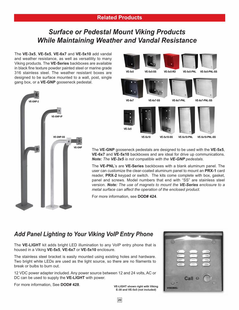
The VE-LIGHT kit adds bright LED illumination to any VoIP entry phone that is
housed in a Viking VE-5x5, VE-6x7 or VE-5x10 enclosure.
The stainless steel bracket is easily mounted using existing holes and hardware.
Two bright white LEDs are used as the light source, so there are no filaments to
break or bulbs to burn out.
12 VDC power adapter included. Any power source between 12 and 24 volts, AC or
DC can be used to supply the VE-LIGHT with power.
For more information, See DOD# 428.
Add Panel Lighting to Your Viking VoIP Entry Phone
VE-LIGHT shown right with Viking
E-30 and VE-5x5 (not included)
VE
-GN
P-2
VE
-GN
P-I
G
VE
-GN
P-S
S
VE
-GN
P
VE-GNP-2
VE-GNP-IP
VE-GNP-SS
VE-GNP
Surface or Pedestal Mount Viking ProductsWhile Maintaining Weather and Vandal Resistance
VE-5x5 VE-5x5-SS VE-5x5-RD VE-5x5-PNL VE-5x5-PNL-SS
VE-6x7 VE-6x7-SS VE-6x7-PNL VE-6x7-PNL-SS
VE-5x10 VE-5x10-SS VE-5x10-PNL VE-5x10-PNL-SS
VE-3x5
The VE-GNP gooseneck pedestals are designed to be used with the VE-5x5,
VE-6x7 and VE-5x10 backboxes and are ideal for drive up communications.
Note: The VE-3x5 is not compatible with the VE-GNP pedestals.
The VE-PNL’s are VE-Series backboxes with a blank aluminum panel. The
user can customize the clear-coated aluminum panel to mount an PRX-1 card
reader, PRX-2 keypad or switch. The kits come complete with box, gasket,
panel and screws. Model numbers that end with “SS” are stainless steel
version. Note: The use of magnets to mount the VE-Series enclosure to ametal surface can affect the operation of the enclosed product.
For more information, see DOD# 424.
The VE-3x5, VE-5x5, VE-6x7 and VE-5x10 add vandal
and weather resistance, as well as versatility to many
Viking products. The VE-Series backboxes are available
in black fine texture powder painted steel or marine grade
316 stainless steel. The weather resistant boxes are
designed to be surface mounted to a wall, post, single
gang box, or a VE-GNP gooseneck pedestal.
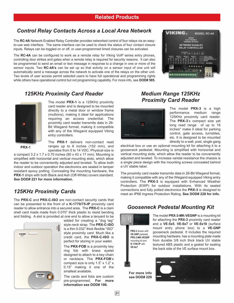
Gooseneck Pedestal Mounting KitThe model PRX-3-MK-VEGNP is a mounting kit
for attaching the PRX-3 proximity card reader
and a VE-5x5, VE-6x7 or VE-5x10 (surface
mount entry phone box) to a VE-GNP
gooseneck pedestal. It includes the required
mounting hardware, has a mounting plate made
from durable 3/8 inch thick black UV stable
textured ABS plastic and a gasket for sealing
the back side of the VE surface mount box.
Medium Range 125KHzProximity Card Reader
The model PRX-3 is a high
performance medium range
125KHz proximity card reader.
The PRX-3’s compact size yet
long read range of up to 16
inches* make it ideal for parking
control, gate access, turnstiles,
etc. It is designed to be mounted
directly to a wall, post, single gang
electrical box or use an optional mounting kit for attaching it to a
gooseneck pedestal. Mounting is simplified with horizontal and
vertical mounting slots, which allow the reader to be conveniently
adjusted and leveled. To increase vandal resistance the chassis is
a single piece design with the mounting screws concealed behind
a UV stable label.
The proximity card reader transmits data in 26-Bit Wiegand format,
making it compatible with any of the Wiegand equipped Viking entry
controllers. The PRX-3 is equipped with Enhanced Weather
Protection (EWP) for outdoor installations. With its sealed
connections and fully potted electronics the PRX-3 is designed to
meet an IP66 Ingress Protection Rating. See DOD# 228 for info.
125KHz Proximity Card ReaderThe model PRX-1 is a 125KHz proximity
card reader and is designed to be mounted
directly to a metal door or window frame
(mullions), making it ideal for applications
requiring an access credential. The
proximity card reader transmits data in 26-
Bit Wiegand format, making it compatible
with any of the Wiegand equipped Viking
entry controllers.
The PRX-1 delivers non-contact read
ranges up to 6 inches (152 mm), and
operates from 5 to 14 VDC. Physical size is
a compact 3.2 x 1.7 x 0.70 inches (80 x 43 x 17 mm). Mounting is
simplified with horizontal and vertical mounting slots, which allow
the reader to be conveniently adjusted and leveled. To allow both
indoor and outdoor operation the electronics are sealed in tamper
resistant epoxy potting. Concealing the mounting hardware, the
PRX-1 ships with both Black and Ash (Off-White) covers standard.
See DOD# 221 for more information.
21
Control Relay Contacts Across a Local Area Network
The RC-4A Network Enabled Relay Controller provides networked control of four relays via an easy-
to-use web interface. The same interface can be used to check the status of four contact closure
inputs. Relays can be toggled on or off, or user-programmed timed closures can be activated.
The RC-4A can be configured to work as a remote relay for Viking VoIP series entry phones,
controlling door strikes and gates when a remote relay is required for security reasons. It can also
be programmed to send an email or text message in response to a change in one or more of the
sensor inputs. Two RC-4A’s can be set up so that activity on a sensor input of one unit will
automatically send a message across the network to activate one of the relays on the other unit.
Two levels of user access permit selected users to have full operational and programming rights
while others have operational control but not programming capability. For more info, see DOD# 585.
PRX-3 shown withVE-GNP pedestal,PRX-3-MK-VEGNPmounting kit and K-1700-IP with VE-6x7
PRX-1
Related Products
125KHz Proximity CardsThe PRX-C and PRX-C-ISO are non-contact security cards that
can be presented to the front of a K-1770/75-IP proximity card
reader to allow entrance into a secured area. The PRX-C is a clam
shell card made made from 0.070” thick plastic to resist bending
and folding. A slot is provided at one end to allow a lanyard to be
added for creating a “dog tag”
style neck strap. The PRX-C-ISO
is a thin 0.032” thick flexible “ISO”
style proximity card. Much like a
credit card, the PRX-C-ISO is
perfect for storing in your wallet.
The PRX-FOB is a proximity key
ring fob with brass eyelet
designed to attach to a key chain
or necklace. The PRX-FOB’s
compact size is only 1.5” x 1.2” x
0.15” making it one of the
smallest available.
The cards and fobs are custom
pre-programmed. For more
information see DOD# 198.
For more info
see DOD# 229
22
Printed in the U.S.A. ZF303670 REV A
Due to the dynamic nature of the product design, the information contained in this document is subject to change without notice. Viking Electronics, and its affiliates and/or subsidiaries
assume no responsibility for errors and omissions contained in this information. Revisions of this document or new editions of it may be issued to incorporate such changes.
DOD# 253
Product Support: (715) 386-8666
IF YOU HAVE A PROBLEM WITH A VIKING PRODUCT, CONTACT: VIKING TECHNICAL SUPPORT AT (715) 386-8666
Our Technical Support Department is available for assistance Monday 8am - 4pm and Tuesday through Friday 8am - 5pm central time. So that we can
give you better service, before you call please:
1. Know the model number, the serial number and what software version you have (see serial label).
2. Have your Product Manual in front of you.
3. It is best if you are on site.
RETURNING PRODUCT FOR REPAIRThe following procedure is for equipment that needs repair:
1. Customer must contact Viking's Technical Support Department at 715-386-8666 to obtain a Return Authorization (RA) number. The customer MUST
have a complete description of the problem, with all pertinent information regarding the defect, such as options set, conditions, symptoms, methods to
duplicate problem, frequency of failure, etc.
2. Packing: Return equipment in original box or in proper packing so that damage will not occur while in transit. Static sensitive equipment such as a
circuit board should be in an anti-static bag, sandwiched between foam and individually boxed. All equipment should be wrapped to avoid packing
material lodging in or sticking to the equipment. Include ALL parts of the equipment. C.O.D. or freight collect shipments cannot be accepted. Ship
cartons prepaid to: Viking Electronics, 1531 Industrial Street, Hudson, WI 54016
3. Return shipping address: Be sure to include your return shipping address inside the box. We cannot ship to a PO Box.
4. RA number on carton: In large printing, write the R.A. number on the outside of each carton being returned.
RETURNING PRODUCT FOR EXCHANGEThe following procedure is for equipment that has failed out-of-box (within 10 days of purchase):
1. Customer must contact Viking’s Technical Support at 715-386-8666 to determine possible causes for the problem. The customer MUST be able to
step through recommended tests for diagnosis.
2. If the Technical Support Product Specialist determines that the equipment is defective based on the customer's input and troubleshooting, a Return
Authorization (R.A.) number will be issued. This number is valid for fourteen (14) calendar days from the date of issue.
3. After obtaining the R.A. number, return the approved equipment to your distributor, referencing the R.A. number. Your distributor will then replace the
Viking product using the same R.A. number.
4. The distributor will NOT exchange this product without first obtaining the R.A. number from you. If you haven't followed the steps listed in
1, 2 and 3, be aware that you will have to pay a restocking charge.
TWO YEAR LIMITED WARRANTYViking warrants its products to be free from defects in the workmanship or materials, under normal use and service, for a period of two years from the date of purchase
from any authorized Viking distributor. If at any time during the warranty period, the product is deemed defective or malfunctions, return the product to Viking Electronics, Inc.,1531 Industrial Street, Hudson, WI., 54016. Customer must contact Viking's Technical Support Department at 715-386-8666 to obtain a Return Authorization (R.A.) number.
This warranty does not cover any damage to the product due to lightning, over voltage, under voltage, accident, misuse, abuse, negligence or any damage caused by useof the product by the purchaser or others. This warranty does not cover non-EWP products that have been exposed to wet or corrosive environments. This warranty does notcover stainless steel surfaces that have not been properly maintained.
NO OTHER WARRANTIES. VIKING MAKES NO WARRANTIES RELATING TO ITS PRODUCTS OTHER THAN AS DESCRIBED ABOVE AND DISCLAIMS ANY EXPRESSOR IMPLIED WARRANTIES OR MERCHANTABILITY OR FITNESS FOR ANY PARTICULAR PURPOSE.
EXCLUSION OF CONSEQUENTIAL DAMAGES. VIKING SHALL NOT, UNDER ANY CIRCUMSTANCES, BE LIABLE TO PURCHASER, OR ANY OTHER PARTY, FORCONSEQUENTIAL, INCIDENTAL, SPECIAL OR EXEMPLARY DAMAGES ARISING OUT OF OR RELATED TO THE SALE OR USE OF THE PRODUCT SOLDHEREUNDER.
EXCLUSIVE REMEDY AND LIMITATION OF LIABILITY. WHETHER IN AN ACTION BASED ON CONTRACT, TORT (INCLUDING NEGLIGENCE OR STRICT LIABILITY)OR ANY OTHER LEGAL THEORY, ANY LIABILITY OF VIKING SHALL BE LIMITED TO REPAIR OR REPLACEMENT OF THE PRODUCT, OR AT VIKING'S OPTION,REFUND OF THE PURCHASE PRICE AS THE EXCLUSIVE REMEDY AND ANY LIABILITY OF VIKING SHALL BE SO LIMITED.
IT IS EXPRESSLY UNDERSTOOD AND AGREED THAT EACH AND EVERY PROVISION OF THIS AGREEMENT WHICH PROVIDES FOR DISCLAIMER OFWARRANTIES, EXCLUSION OF CONSEQUENTIAL DAMAGES, AND EXCLUSIVE REMEDY AND LIMITATION OF LIABILITY, ARE SEVERABLE FROM ANY OTHERPROVISION AND EACH PROVISION IS A SEPARABLE AND INDEPENDENT ELEMENT OF RISK ALLOCATION AND IS INTENDED TO BE ENFORCED AS SUCH.
If trouble is experienced with the K-1700-IP phone, for repair or warranty information, please contact:
Viking Electronics, Inc., 1531 Industrial Street, Hudson, WI 54016 (715) 386-8666
WHEN PROGRAMMING EMERGENCY NUMBERS AND (OR) MAKING TEST CALLS TO EMERGENCY NUMBERS:Remain on the line and briefly explain to the dispatcher the reason for the call. Perform such tests in off-peak hours, such as early morning or late evenings.
PART 15 LIMITATIONSThis equipment has been tested and found to comply with the limits for a Class A digital device, pursuant to Part 15 of the FCC Rules. These limits are
designed to provide reasonable protection against harmful interference when the equipment is operated in a commercial environment. This equipment
generates, uses, and can radiate radio frequency energy and, if not installed and used in accordance with the instruction manual, may cause harmful
interference to radio communications. Operation of this equipment in a residential area is likely to cause harmful interference in which case the user will
be required to correct the interference at his own expense.
Warranty