jwst telescope integration and test progress - nasa telescope integration and test progress gary w....
TRANSCRIPT

JWST telescope integration and test progress
Gary W. Matthewsa, Tony L. Whitman
a, Lee D. Feinberg
b, Mark F. Voyton
b, Juli A. Lander
b,
Ritva Keski-Kuhab
aHarris (United States), bNASA Goddard Space Flight Center (United States)
ABSTRACT
The James Webb Space Telescope (JWST) is a 6.5m, segmented, IR telescope that will explore the first light of the
universe after the big bang. The JWST Optical Telescope Element (Telescope) integration and test program is well
underway. The telescope was completed in the spring of 2016 and the cryogenic test equipment has been through two
optical test programs leading up to the final flight verification program. The details of the telescope mirror integration
will be provided along with the current status of the flight observatory. In addition, the results of the two optical ground
support equipment cryo tests will be shown and how these plans fold into the flight verification program.
Keywords: JWST, Telescope, Integration, Test, Cryo
1. INTRODUCTION
The James Webb Space Telescope (Figure 1.1) is the successor to the Hubble Space Telescope. JWST will operate in the
infrared region of the electromagnetic spectrum to allow the science community to observe far red shifted stars and
galaxies as they were originally forming after the Big Bang 13.8 billion
years ago. The scientists call JWST the first light machine since it will
actually observe the first stars “turning on” and early galaxy formation. Even
though the light from these early stars and galaxies was created billions of
years ago, that light is just getting to our solar system now. They are moving
away from us at nearly the speed of light Doppler-shifting the visible light
into the infrared. In order to image this phenomenon, the telescope must also
image in the infrared spectrum. This means that the telescope and all the
systems that create that image must be very cold. That is why JWST
operates at 40°K. This extreme temperature creates many challenges for the
engineers and scientists that are building and testing the observatory. This
paper will provide an overview of the Alignment, Integration, and Test
(AI&T) program and provide specific details on the OTIS integration effort
and the preparation for the final cryo test before the OTIS delivery to JSC.
2. OTIS INTEGRATION
The subsystems that will comprise the final observatory are completed. The Optical Telescope Element (OTE)
integration has been discussed in paper 9904-2 in these conference proceedings. The Integrated Science Instrument
Module also successfully completed its cryogenic verification test program. The next step is the completion of what is
commonly called the OTIS (OTE plus ISIM). In reality, the ISIM is more than just the instruments. Figure 2.1 provides
an overview of the three major components of the ISIM. The figure shows the ISIM that contains the physical
instruments. There is also the IEC (ISIM Electronics Compartment) and the HR (Harness Radiator). The OTIS also has
various thermal radiators and blankets that need to be installed in order to finalize the flight configuration.
Figure 1.1: The James Webb Space
Telescope in its fully deployed
configuration.
https://ntrs.nasa.gov/search.jsp?R=20160008975 2018-06-22T13:31:27+00:00Z

Figure 2.1: The ISIM components are
shown above. Upper left – ISIM
instruments, Middle – Harness radiator,
Bottom – ISIM Electronics compartment.
Figure 2.2: The completed
OTE is show in the assembly
stand.
Figure 2.3: The OTE was moved from the
assembly stand shown at the top of the
photograph to the High Capacity Roll and
Turnover Fixture. Some blanketing and
radiator installation will occur here before
being flipped over for ISIM integration.
To install the ISIM, the telescope needs to be flipped over to provide access to the rear of the Backplane Support Frame.
In order to do that, the telescope is moved from the integration stand (Figure 2.2) over to the High Capacity Roll and
Turnover Fixture (Figure 2.3). While it is this configuration, thermal blankets and a large radiator are attached before the
reach and access are blocked due to the ISIM installation and before being turned over, the protective covers that have
covered the gold-coated mirrors have to be removed since they are merely sitting on the mirrors. The “big reveal” took
place over two days with technicians removing the covers (Figure 2.4). Needless to say, this was a very exciting time for
the JWST team and a proud moment for Dr. John Mather in the ultimate selfie in a reflection off the 18 segment primary
mirror (Figure 2.5).
Figure 2.4: Before flipping over, the
protective covers have to be removed by
technicians on diving boards (left). The
primary mirror, fully revealed, is finally
visible (right).
Figure 2.5: Dr. John Mather’s
reflection can be seen in the primary
mirror.
Figure 2.6: The OTE is shown
rotated and placed back in the
assembly stand in preparation for
ISIM integration.
Once rotated with the primary mirror facing down, the OTE was placed back in the assembly stand (Figure 2.6) in
preparation for the ISIM integration. Rolling platforms were included in the assembly stand to allow excellent reach and
access behind the mirrors and into the ISIM cavity in the telescope backplane structure. A specially designed extendable
diving board was also designed that actually extends through the telescope that allows access to the interior of the
telescope structure. The ISIM will be attached to the telescope via six kinematic struts that are shown in Figure 2.7.
These struts are adjustable in length allowing the ISIM to be aligned to the telescope. Critical metrology measurements
provide the data to align the telescope and instrument pupil locations in zero gravity at cryo temperatures. To accomplish

this in gravity and room temperature, calibrated finite element models are used to bias the installation location so that the
optimal alignment is achieved once on-orbit. Figure 2.8 shows the ISIM being installed into the telescope.
Figure 2.7: The ISIM instrument subsystem is attached to
the telescope via six kinematic struts (Two monopods and
two bipods). These struts are adjustable to allow the
telescope and instrument pupils to be aligned.
Figure 2.8: The ISIM is carefully lowered into the telescope
and attached via the 6 struts.
This paper did not allow the inclusion of the remaining subsystems
prior to the publication date. The hardware is comprised mainly of
thermal radiators and thermal management hardware and is staged and
ready for installation per plan.
Once the OTIS is completed, it will go through a series of
environmental tests at the Goddard Space Flight Center. This includes
a pre and post center of curvature testing of the telescope with a three-
axis vibration test and an acoustic test program to verify the ability to
withstand the rigors of the launch to space. Once that is completed, the
STTARS (Space Telescope Transporter for Air Road and Sea)
shipping container (Figure 2.9) will be used to move the OTIS from
Maryland to the Johnson Space Center in Houston, Texas. Once there,
an end-to-end optical test will be done at the operating temperature in
order to verify the on-orbit performance of the system.
In preparation for that critical test program, a series of tests using the
JWST Pathfinder telescope has been ongoing for the past year. A series
of three tests are planned prior to the OTIS test. Optical Ground
Support Equipment (OGSE) Test #1 and #2 are complete. A final
Thermal Pathfinder (TPF) test is planned to start late summer 2016.
3. JSC ENVIRONMENTAL TEST SYSTEM
The cryogenic testing will take place at the Johnson Space Center (JSC) in Houston, Texas. The JSC Chamber A is a
legacy vacuum chamber originally built for the Apollo program in the 1960’s. This chamber was never intended to be an
optical test chamber or a cryogenic test facility capable of creating a 20K test environment. Therefore, a major retrofit
was in order that took several years to complete.
The basic chamber was fully functional and with its large 40-foot (12.2m) diameter door, it was really a perfect choice
for JWST. Therefore, the original solar lamps that illuminated the Apollo Command Module (Figure 3.1) were removed
and the existing liquid Nitrogen (LN2) shrouds were refurbished. While that was going on, an inner set of thermal
shrouds were fabricated and installed that would support the gaseous Helium (GHe) cryogen enabling a 20K test
Figure 2.9: Once completed, the STARRS
shipping container will be used to move the
system to the Johnson Space Center in Houston,
Texas for the cryogenic optical test.
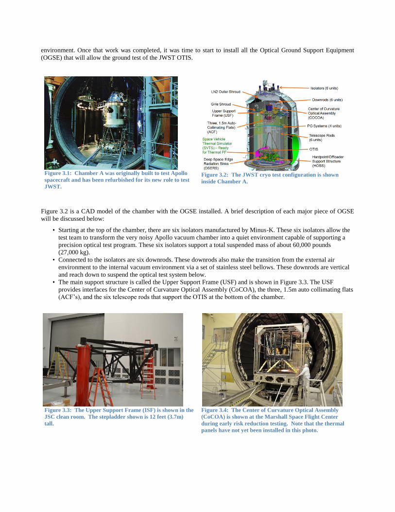
environment. Once that work was completed, it was time to start to install all the Optical Ground Support Equipment
(OGSE) that will allow the ground test of the JWST OTIS.
Figure 3.1: Chamber A was originally built to test Apollo
spacecraft and has been refurbished for its new role to test
JWST.
Figure 3.2: The JWST cryo test configuration is shown
inside Chamber A.
Figure 3.2 is a CAD model of the chamber with the OGSE installed. A brief description of each major piece of OGSE
will be discussed below:
• Starting at the top of the chamber, there are six isolators manufactured by Minus-K. These six isolators allow the
test team to transform the very noisy Apollo vacuum chamber into a quiet environment capable of supporting a
precision optical test program. These six isolators support a total suspended mass of about 60,000 pounds
(27,000 kg).
• Connected to the isolators are six downrods. These downrods also make the transition from the external air
environment to the internal vacuum environment via a set of stainless steel bellows. These downrods are vertical
and reach down to suspend the optical test system below.
• The main support structure is called the Upper Support Frame (USF) and is shown in Figure 3.3. The USF
provides interfaces for the Center of Curvature Optical Assembly (CoCOA), the three, 1.5m auto collimating flats
(ACF’s), and the six telescope rods that support the OTIS at the bottom of the chamber.
Figure 3.3: The Upper Support Frame (ISF) is shown in the
JSC clean room. The stepladder shown is 12 feet (3.7m)
tall.
Figure 3.4: The Center of Curvature Optical Assembly
(CoCOA) is shown at the Marshall Space Flight Center
during early risk reduction testing. Note that the thermal
panels have not yet been installed in this photo.

• The CoCOA (Figure 3.4) is one of the major optical test systems for the JWST cryo test. The essence of the
CoCOA is basically a two element null and a 4D multiwavelength interferometer (MWIF). The MWIF allows the
test team to quickly align and phase the segmented primary mirror. It also provides a full aperture evaluation of
the primary mirror since we only sample the end-to-end system aperture through our three subaperture ACF’s.
There are various features within the CoCOA to aid in the identification and alignment of the primary mirror. See
Reference 2 for a complete discussion of the CoCOA.
• The three ACF’s are lightweight borosilicate mirrors manufactured by HEXTEK (Figure 3.5). Borosilicate was
used for the ACF’s since the operating temperature of the mirrors is at the zero coefficient of expansion (CTE) of
the glass. Therefore, the surface figure is very stable at the cryo test temperatures. The ACF’s are cryo null
figured at the operating temperature prior to installation at JSC.
Figure 3.5: The ACF assembly is shown with the
three-actuator assemblies suspending the 1.5m
lightweight mirror underneath.
Figure 3.6: The Hardpoint/Offleader Support Structure (HOSS)
is shown after painting. The structure is approximately 30 feet
(9m) in length and width.
• There are six telescope rods that hang from the USF and
support the Hardpoint/Offloader Support Structure
(HOSS). The very large stainless steel structure
(Figure 3.6) holds the flight OTIS in a kinematic
configuration of two monopod struts on one end and two
sets of bipods on the other end.
• There are four photogrammetry (PG) systems
manufactured by Johns Hopkins University Instrument
Development Group that are attached to the walls of the
chamber (Figure 3.7). The camera systems inside
pressure tight enclosures that are thermally controlled.
Each system rotates in a windmill fashion through 360
degrees of rotation. This PG system allows the test team
to understand where the hardware is in the chamber to
about 100 microns.
This comprises the Optical Ground Support Equipment that will
be used to test the flight OTIS. There is additional thermal
ground support equipment that completes the test equipment suite. The thermal equipment is discussed in Section 5.
4. OPTICAL GSE TEST PROGRAM RESULTS
One of the main purposes of the Pathfinder telescope was to exercise all the test equipment, the test processes, and the
test personnel; proving to be valuable experiential training for the upcoming test on the OTIS. The Pathfinder includes
two Primary Mirror Segment Assemblies (PMSAs) and a Secondary Mirror Assembly (SMA) with nearly similar
functions as the OTIS mirrors (Figure 4.1). A simulator for the Science Instruments, called the Beam Image Analyzer
Figure 3.7: The four-photogrammetry systems are
shown in their final “windmill” configuration in the
JSC vacuum chamber.

(BIA), placed a near infrared detector array, similar to arrays in the
Science Instruments, at the Pathfinder telescope focal surface on
stages to allow translation in all directions and small tilts to allow
placing the detector anywhere on the focal surface.
The Pathfinder optical tests consisted of two cryogenic test cycles.
The first test cycle, OGSE 1, tested the full test configuration without
the prime Aft Optical Assembly (AOS), which contains the fine
steering mirror and the tertiary mirror. The second test cycle, OGSE
2, added the AOS and the AOS Source Plate Assembly (ASPA) with
its optical point sources at the Cassegrain focus to allow the
execution of all optical tests before delivering the AOS for
integration into the OTE.
The first order of business was to check alignments after a ~250° K
cool down. From photogrammetry measurements, the alignment of
the primary mirror relative to the CoCOA and the ACFs were well
within tolerance. The CoCOA allows 6 degrees of freedom, although clocking about the optical axis is not used. Table
4.1 shows the ample remaining adjustment range available after the cool down alignment shift for the CoCOA.
Table 4-1: Remaining range of adjustment in the CoCOA after the alignment shift from the cool down.
V1
(mm)
V2
(mm)
V3
(mm)
RV1
(µrad)
RV2
(µrad)
RV3
(µrad)
Range +/- 24.6 +/- 32 +/- 32 N/A +/-5.6 +/-5.6
Cryo Position (margin) -7.4
(70%)
7.2
(76%)
0.4
(98%) -0.6
0.5
(92%)
-0.5
(90%)
The ACFs have adjustment in tilt to move the collimated beam to selected field angles and piston, though piston is not
used. Knowledge of the decenter and clocking positions of the ACF optical surfaces is important to remove the ACF
surface figure from the telescope’s images. The decenter position is also limited to prevent light leakage from adjacent
PMSAs during Wavefront Sense and Control operations for the three PMSAs within the clear aperture of the ACF. The
two Pathfinder tests only had one of the three ACFs installed – the ACF reflecting through the two PMSAs on the
Pathfinder. The alignment and function of the other two ACFs will occur in the upcoming thermal test of the Pathfinder
(Section 5 below). Table 4.2 shows the range margin for the tilt relative to the PM and the position margin for decenter
relative to the PMSAs.
Table 4-2: Remaining tilt range of adjustment in the ACF and the decenter position relative to tolerance after the alignment
shift from the cool down.
Decenter
(mm)
Tilt
(mrad)
Range 10.8
Cryo Position (margin) (70%) 0.15
(99%)
Figure 4.1: Pathfinder telescope with flight AOS
before second cryogenic test.
Photogrammetry is then used to align the PM and SM relative to the AOS (Reference 14). The accuracy of the
photogrammetry system was compared against laser tracker measurements prior to the cryogenic tests. The measured
dimensions of Invar bars with measured coefficients of thermal expansion and the dimensions of the beryllium mirrors
were checked against expectations at the cryogenic test temperatures. The repeatability at cryogenic temperatures was
also determined (Reference 15). The results did reveal issues with the mechanical interface of a few of the
photogrammetry targets with the PMSAs that will be resolved before the OTIS test. Table 4.3 shows the repeatability of
the photogrammetry system. With this repeatability, Table 4.4 contains the accuracy of the measurements.
Table 4-3: Example repeatability measurements
with the photogrammetry system.
Table 4-4: Photogrammetry accuracy.
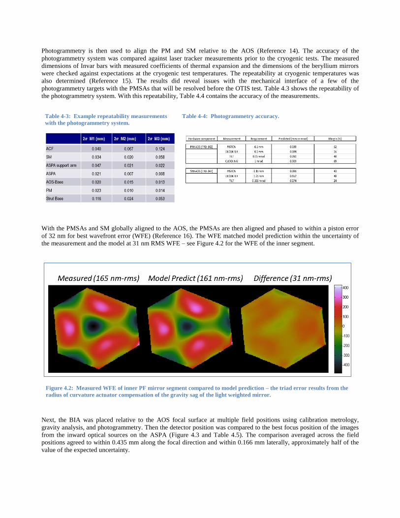
With the PMSAs and SM globally aligned to the AOS, the PMSAs are then aligned and phased to within a piston error
of 32 nm for best wavefront error (WFE) (Reference 16). The WFE matched model prediction within the uncertainty of
the measurement and the model at 31 nm RMS WFE – see Figure 4.2 for the WFE of the inner segment.
Next, the BIA was placed relative to the AOS focal surface at multiple field positions using calibration metrology,
gravity analysis, and photogrammetry. Then the detector position was compared to the best focus position of the images
from the inward optical sources on the ASPA (Figure 4.3 and Table 4.5). The comparison averaged across the field
positions agreed to within 0.435 mm along the focal direction and within 0.166 mm laterally, approximately half of the
value of the expected uncertainty.
Figure 4.2: Measured WFE of inner PF mirror segment compared to model prediction – the triad error results from the
radius of curvature actuator compensation of the gravity sag of the light weighted mirror.

Figure 4.3: ASPA Inward source is imaged by AOS and best focus position compared to detector position set by
photogrammetry.
Table 4-5: Comparison of image location based in phase retrieval analysis of image vs. expected location based on metrology
and finite element model predictions.
Best Image Location Metrology Location PRMS - Prediction
Instrument
FOV
ASPA
Source
Designation M1 (mm) M2 (mm) M3 (mm) M1 (mm) M2 (mm) M3 (mm) dM1
(mm)
dM2
(mm)
dM3
(mm)
NIRCamB I-1 -1809.338 -41.378 -325.920 -1810.325 -41.515 -325.799 0.987 0.137 -0.120
NIRCamB I-3 -1811.261 -34.780 -332.990 -1811.839 -34.835 -332.594 0.578 0.055 -0.395
NIRCamB I-4 -1811.047 -34.666 -332.468 -1811.839 -34.835 -332.594 0.792 0.168 0.127
NIRCamA I-5 -1808.646 89.324 -347.837 -1809.430 88.997 -347.686 0.784 0.327 -0.151
NIRCamA I-6 -1808.681 88.822 -347.878 -1809.430 88.997 -347.686 0.749 -0.176 -0.192
FGS1 I-7 -1790.147 156.513 -462.293 -1790.725 156.482 -462.090 0.579 0.030 -0.204
FGS1 I-8 -1791.067 163.177 -462.404 -1791.598 163.164 -462.228 0.531 0.013 -0.176
FGS1 I-9 -1793.820 163.421 -469.502 -1793.987 163.321 -469.287 0.167 0.099 -0.215
FGS2 I-11 -1793.662 -15.854 -462.467 -1794.608 -15.915 -462.375 0.946 0.060 -0.092
FGS2 I-13 -1796.089 -9.200 -469.493 -1796.959 -9.269 -469.399 0.870 0.069 -0.094
NIRISS I-15 -1786.456 -216.090 -456.663 -1786.327 -216.140 -456.396 -0.129 0.051 -0.267
NIRISS I-16 -1783.960 -215.915 -449.566 -1784.044 -215.989 -449.378 0.084 0.074 -0.188
MIRI I-23 -1808.903 -277.834 -238.417 -1808.916 -278.029 -238.552 0.013 0.195 0.135
MIRI I-24 -1809.133 -277.921 -238.937 -1808.916 -278.029 -238.552 -0.217 0.108 -0.385
NIRSPEC I-25 -1803.834 292.103 -271.288 -1804.099 292.001 -271.097 0.265 0.102 -0.191
NIRSPEC I-26 -1805.759 298.933 -271.463 -1805.724 298.839 -271.217 -0.035 0.094 -0.247
Average 0.435 0.088 -0.166
StdDev 0.410 0.103 0.144
Range 1.204 0.503 0.530

These measurements also provided a measurement
of the AOS WFE for each field point to compare
to the model prediction. The comparison varied
between 9 and 40nm RMS WFE across the seven
measured field points – less than the variation
between alternative analysis software.
The Secondary Mirror focus position was set by
using an upward source on the ASPA to retro-
reflect from the auto-collimating flat mirror near
the top of the chamber to form an image on the
BIA detector, and then moving the SM to set the
focus to the detector position. Due to higher than
expected vibration of the primary mirror segments,
the images from the two segments required
separation to analyze the images without confusion
from the vibration effect. By calibrating the
relative tilt positions of the segments with the CoCOA, a Hartmann analysis could be used to determine focus and other
lower order image quality measurements (Reference 17) nearly as well as stable phased PMSAs within the ACF
subaperture (Figure 4.4).
Other parameters were measured including the PM collection area with an interferometer camera image, practice of the
radius of curvature measurement with a Leica Absolute Distance Meter, and plate scale by tilting the ACF and a PMSA.
The alignment of the primary mirror to the pupil mask near the Fine Steering Mirror in the AOS is accomplished by
using linear arrays of LEDs at the PM edge and detecting which LEDs pass through the mask to reach the BIA detector.
The LED locations are determined using metrology, finite element model predictions, and photogrammetry. Since the
LED light does not pass through the PMSAs, this image is similar to the flight test. Figure 4.5 has a schematic of the
LED locations and the test image of the LEDs that passed through the mask. The BIA has a second detector with a
singlet lens to create the pupil image. Table 4.6 shows the nominal vs. actual alignment measured in the Pathfinder. The
result was a measured 0.3% pupil shear from the nominal alignment.
Figure 4.5: Schematic of linear LED array locations relative to primary mirror. Light emits towards the Secondary Mirror.
Table 4-6: Schematic of linear Led array locations relative to primary mirror. Light emits towards the Secondary Mirror.
Bar 1 2 3 4 5 6
Nominal Last visible LED 20 18 21 17 13 16
Actual last visible LED 19 18 22 18 13 17
Figure 4.4: Sensitivity of Hartmann configuration of the PMSAs
compared to the baseline approach of phased mirror segments.

Finally, an important test checked all the light paths
through the ASPA structure and the AOS aperture in the
cryogenic vacuum environment. This establishes a
baseline image for the OTIS test. Any deviations in the
image during the OTIS test can be confidently attributed
to the structure between the AOS and the instrument
detectors. This image is created using the LEDs
mentioned above as a source. Since the LEDs are at a
pupil conjugate, the imaged light (without a pupil
imaging lens) spreads across the detector plane at the
focal conjugate. Figure 4.6 shows the test image from
the Pathfinder test.
5. PLANS FORWARD TO OTIS CRYO TEST
As the OTIS integration, work continues at GSFC in the SSDIF clean room, work is progressing to finalize the
configuration for the Thermal Pathfinder (TPF) test at JSC. The Pathfinder has been fitted with thermal blankets and
mirror simulators (Figure 5.1) to replicate as well as possible the flight configuration of the OTIS.
Figure 5.1: The Pathfinder has been fitted with mirror
simulators for the Pathfinder thermal test. The HOSS is
shown on the left side of the photograph.
Figure 5.2: The DSERS and SVTS are shown on the HOSS.
The flight system sits inside these thermal components to
simulate the flight environment at L2.
The ground support equipment is also being fitted with all the additional thermal hardware that was not needed for
OGSE#1 and OGSE#2. This includes the Space Vehicle Thermal Simulator (SVTS) and Deep Space Edge Radiator
Systems (DSERS) that are shown in the Figure 5.2 CAD drawing. Basically, the OTIS sits in a tub of specially designed
actively cooled radiators that mimic the space environment. The SVTS simulates the spacecraft bus and the transition
from the warm sun facing side to the cold observatory side.
The TPF test will allow the test team to actually practice the cool down and observe the steady state environment that
will be used for the flight OTIS. In addition, the performance of the thermal system can be evaluated to insure that the
provided environment will provide the rigorous test program parameters required to insure that the OTIS would operate
as expected at L2.
6. SUMMARY
The OTIS AI&T program is progressing per plan. The OTIS integration is well underway at the Goddard Space Flight
Center and the final Pathfinder cryo test is being configured for later this summer.
The OTIS cryo test is less than a year away!
Figure 4.6: Image created by scanning the BIA detector without
a pupil imaging lens through the field using light from some
LEDs used in the pupil alignment test.

REFERENCES AND RELATED PAPERS
[1] Optomechanical Integration and Alignment Verification of the James Webb Space Telescope (JWST)
Optical Telescope Element
Conrad Wells, Matthew Coon, ITT Space Systems Division (United States)
Published in Proceedings Volume 7433: August 2009
[2] The Center of Curvature Optical Assembly for the JWST Primary Mirror Cryogenic Optical Test: Optical
Verification
Conrad Wells, Gene Olczak, Cormic Merle, Tom Dey, Mark Waldman, Tony Whitman, Eric Wick, Aaron Peer,
ITT Corp. Geospatial Systems (United States)
Published in Proceedings Volume 7790: August 2010
[3] Architecting a Revised Optical Test Approach for JWST
Charlie Atkinson, Jonathan Arenberg, Northrop Grumman (United States); Gary Matthews, Mark Waldman, Alan
Wertheimer, Tony Whitman, ITT (United States); Jim Oschmann, Ball Aerospace & Technologies Corp. (United
States)
Published in Proceedings Volume 7010: August 2008
[4] The Center of Curvature Optical Assembly for the JWST Primary Mirror Cryogenic Optical Test
Conrad Wells, Gene Olczak, Cormic Merle, Tom Dey, Mark Waldman, Tony Whitman, Eric Wick, Aaron Peer,
ITT Geospatial Systems (United States)
Published in Proceedings Volume 7739: July 2010
[5] JWST's Cryogenic Position Metrology System
Tony L. Whitman, ITT Exelis Geospatial Systems (United States); Randolph P. Hammond, Joe Orndorff, Stephen
Hope, Stephen A. Smee, The Johns Hopkins Univ. (United States); Thomas Scorse, Keith A. Havey, Jr., ITT
Exelis Geospatial Systems (United States)
Published in Proceedings Volume 8442: August 2012
[6] The Integration and Test Program of the James Webb Space Telescope
Randy A. Kimble, Pamela S. Davila, Charles E. Diaz, Lee D. Feinberg, Stuart D. Glazer, NASA Goddard Space
Flight Ctr. (United States); Gregory S. Jones, Northrop Grumman Aerospace Systems (United States); James M.
Marsh, NASA Goddard Space Flight Ctr (United States); Gary W. Matthews, ITT Exelis Geospatial Systems
(United States); Douglas B. McGuffey, NASA Goddard Space Flight Ctr. (United States); Patrick H. O'Rear,
NASA Johnson Space Flight Ctr. (United States); Deborah D. Ramey, NASA Goddard Space Flight Ctr. (United
States); Carl A. Reis, NASA Johnson Space Flight Ctr. (United States); Scott C. Texter, Northrop Grumman
Aerospace Systems (United States); Tony L. Whitman, ITT Exelis Geospatial Systems (United States)
Published in Proceedings Volume 8442: August 2012
[7] Assembly Integration and Ambient Testing of the James Webb Space Telescope Primary Mirror
Conrad Wells, Tony Whitman, John Hannon, Art Jensen, Eastman Kodak Co. (United States)
Published in Proceedings Volume 5487: October 2004
[8] Integration and Verification of the James Webb Space Telescope
Charles B. Atkinson, Pat Harrison, Northrop Grumman Corp. (United States); Gary Matthews, Eastman Kodak
Co. (United States); Paul Atcheson, Ball Aerospace& Technologies Corp. (United States)
Published in Proceedings Volume 5180: December 2003

[9] James Webb Space Telescope System Cryogenic Optical Test Plans
Lee D. Feinberg, NASA Goddard Space Flight Ctr. (United States); Allison Barto, Ball Aerospace& Technologies
Corp. (United States); Mark Waldman, Sigma Space Corp. (United States); Tony Whitman, ITT Corp. Geospatial
Systems (United States)
Published in Proceedings Volume 8150: September 2011
[10] James Webb Space Telescope Primary Mirror Integration: Testing the Multiwavelength Interferometer on
the Test Bed Telescope
Gene Olczak, David J. Fischer, Mark Connelly, Conrad Wells, ITT Corp. Geospatial Systems (United States)
Published in Proceedings Volume 8146: September 2011
[11] James Webb Space Telescope (JWST) Optical Telescope Element (OTE) Pathfinder Status and Plans
Lee D. Feinberg, Ritva A. Keski-Kuha, NASA Goddard Space Flight Ctr. (United States); Charles B. Atkinson,
Northrop Grumman Aerospace Systems (United States); Andrew J. Booth, Sigma Space Corp. (United States);
Tony L. Whitman, Exelis Geospatial Systems (United States)
Published in Proceedings Volume 9143: Space Telescopes and Instrumentation 2014: Optical, Infrared, and
Millimeter Wave: September 2014
[12] JWST Telescope Integration and Test Status
Gary W. Matthews, Thomas R. Scorse, Scott Kennard, John Spina, Tony Whitman, Exelis Inc. (United States);
Scott Texter, Charles Atkinson, Greg Young, Northrop Grumman Aerospace Systems (United States); Ritva A.
Keski-Kuha, James M. Marsh, Juli Lander, Lee D. Feinberg, NASA Goddard Space Flight Ctr. (United States)
Published in Proceedings Volume 9143: Space Telescopes and Instrumentation 2014: Optical, Infrared, and
Millimeter Wave: September 2014
[13] Use of a Pathfinder Optical Telescope Element for James Webb Space Telescope Risk Mitigation
Lee D. Feinberg, Ritva Keski-Kuha, NASA Goddard Space Flight Ctr. (United States); Charlie Atkinson, Scott C.
Texter, Northrop Grumman Aerospace Systems (United States)
Published in Proceedings Volume 7731: Space Telescopes and Instrumentation 2010: Optical, Infrared, and
Millimeter Wave: July 2010
[14] Alignment Test Results of the JWST Pathfinder Telescope Mirrors in the Cryogenic Environment Whitman, T.L., Wells, C., Hadaway, J., Knight, J.S., Lunt, S., Proc. SPIE 9904-161, (2016)
[15] Model Predictions and Observed Performance of JWST Cryogenic Position Metrology System Lunt, S., et. al., Proc. SPIE 9904-166, (2016)
[16] Performance of the Primary Mirror Center-of-Curvature Optical Metrology System During Cryogenic
Testing of the JWST Pathfinder Telescope Hadaway, J.B., et. al., Proc. SPIE 9904-150, (2016)
[17] Hartmann Test for the James Webb Space Telescope Knight, J.S., et. al., Proc. SPIE 9904-11, (2016)