juniper srx1400, srx3400, and srx3600 services fips … · juniper networks public material – may...
TRANSCRIPT

Copyright Juniper, 2016 Version 1.3 Page 1 of 30 Juniper Networks Public Material – May be reproduced only in its original entirety (without revision).
Juniper Networks SRX1400, SRX3400, and SRX3600 Services Gateways
Non‐Proprietary FIPS 140‐2 Cryptographic Module Security Policy
Version: 1.3
Date: July 5, 2016
Juniper Networks, Inc. 1133 Innovation Way Sunnyvale, California 94089 USA 408.745.2000 1.888 JUNIPER www.juniper.net

Copyright Juniper, 2016 Version 1.3 Page 2 of 30 Juniper Networks Public Material – May be reproduced only in its original entirety (without revision).
TableofContents
1 Introduction .................................................................................................................... 4
1.1 Hardware and Physical Cryptographic Boundary .........................................................................6 1.2 Mode of Operation .................................................................................................................... 10 1.3 Firmware Load ........................................................................................................................... 11 1.4 Zeroization ................................................................................................................................. 12
2 Cryptographic Functionality ........................................................................................... 13
2.1 Disallowed Algorithms............................................................................................................... 15 2.2 Critical Security Parameters ...................................................................................................... 15
3 Roles, Authentication and Services ................................................................................ 17
3.1 Roles and Authentication of Operators to Roles ...................................................................... 17 3.2 Authentication Methods ........................................................................................................... 17 3.3 Services ...................................................................................................................................... 17
4 Self‐tests ........................................................................................................................ 19
5 Physical Security Policy .................................................................................................. 22
5.1 General Tamper Seal Placement and Application Instructions ................................................. 22 5.2 SRX1400 (16 seals) .................................................................................................................... 22 5.3 SRX3400 (29 seals) .................................................................................................................... 24 5.4 SRX3600 (35 seals) .................................................................................................................... 26
6 Security Rules and Guidance .......................................................................................... 28
7 References and Definitions ............................................................................................ 29
ListofTablesTable 1 – Cryptographic Module Configurations .......................................................................................... 4
Table 2 ‐ Security Level of Security Requirements........................................................................................ 5
Table 3 ‐ Ports and Interfaces .................................................................................................................... 10
Table 4 ‐ Approved and CAVP Validated Cryptographic Functions ............................................................ 13
Table 5 ‐ Non‐Approved but Allowed Cryptographic Functions ................................................................. 14
Table 6 ‐ Protocols Allowed in FIPS Mode .................................................................................................. 14
Table 7 ‐ Critical Security Parameters (CSPs) .............................................................................................. 15
Table 8 ‐ Public Keys .................................................................................................................................... 16
Table 9 ‐ Authenticated Services ................................................................................................................ 17
Table 10 ‐ Unauthenticated traffic .............................................................................................................. 18
Table 11 ‐ CSP Access Rights within Services .............................................................................................. 18
Table 12 – Physical Security Inspection Guidelines .................................................................................... 22
Table 13 – References ................................................................................................................................. 29
Table 14 – Acronyms and Definitions ......................................................................................................... 29
Table 15 – Datasheets ................................................................................................................................. 30

Copyright Juniper, 2016 Version 1.3 Page 3 of 30 Juniper Networks Public Material – May be reproduced only in its original entirety (without revision).
ListofFiguresFigure 1 – SRX1400 Front View ..................................................................................................................... 6
Figure 2 – SRX1400 Bottom View ................................................................................................................. 6
Figure 3 ‐ SRX1400 Left View ........................................................................................................................ 6
Figure 4 ‐ SRX1400 Right View ...................................................................................................................... 7
Figure 5 ‐ SRX1K‐NPC‐SPC‐1‐10‐40 (Excluded Component) ......................................................................... 7
Figure 6 – SRX3400 Top View ........................................................................................................................ 8
Figure 6 – SRX3400 Bottom View ................................................................................................................. 8
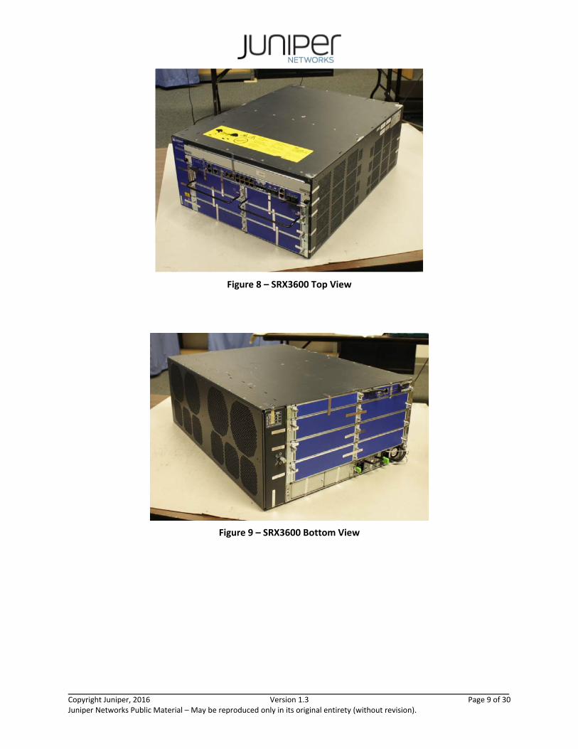
Figure 7 – SRX3600 Top View ........................................................................................................................ 9
Figure 8 – SRX3600 Bottom View ................................................................................................................. 9
Figure 10: SRX1400 Tamper‐Evident Seal Placement on Front & Right Side‐13 Tamper Seals .................. 23
Figure 11: SRX1400 Tamper‐Evident Seal Placement on Left Side‐Three Tamper Seals ............................ 24
Figure 12: SRX3400 Tamper‐Evident Seal Placement on Front and Right Side‐13 Tamper Seals .............. 25
Figure 13: SRX3400 Tamper‐Evident Seal Placement on Rear‐16 Tamper Seals ........................................ 25
Figure 14: SRX3600 Tamper‐Evident Seal Placement on Front and Right Side‐18 Tamper Seals .............. 26
Figure 15: SRX3600 Tamper‐Evident Seal Placement on Rear and Bottom‐ 17 Tamper Seals ................... 27

Copyright Juniper, 2016 Version 1.3 Page 4 of 30 Juniper Networks Public Material – May be reproduced only in its original entirety (without revision).
1 Introduction
The Juniper Networks SRX Series Services Gateways are a series of secure routers that provide essential capabilities to connect, secure, and manage work force locations sized from handfuls to hundreds of users. By consolidating fast, highly available switching, routing, security, and applications capabilities in a single device, enterprises can economically deliver new services, safe connectivity, and a satisfying end user experience. All models run Juniper’s JUNOS firmware – in this case, a specific FIPS‐compliant version called JUNOS‐FIPS, version 12.1X46‐D40. The firmware image is junos‐srx1k3k‐12.1X46‐D40.4‐fips.tgz and the firmware Status service identifies itself as in the “Junos 12.1X46‐D40.4 (FIPS edition)”.
This Security Policy covers the SRX1400, SRX3400, and SRX3600 models. They are meant for data centers, service provider networks, etc.
The cryptographic modules are defined as multiple‐chip standalone modules that execute JUNOS‐FIPS firmware on any of the Juniper Networks SRX‐Series gateways listed in the table below.
Table 1 – Cryptographic Module Configurations
Model Hardware Versions Firmware Distinguishing Features
SRX1400
SRX1400BASE‐GE‐AC SRX1400BASE‐GE‐DC SRX1400BASE‐XGE‐AC SRX1400BASE‐XGE‐DC
with
SRX1K‐NPC‐SPC‐1‐10‐40 SRX3K‐SPC‐1‐10‐40
JUNOS‐FIPS 12.1X46‐D40
9 or 12 x 10/100/1000 + 0 or 3 10 GbE; 1 x single‐wide SRX3000 IOC slot
SRX3400
SRX3400BASE‐AC SRX3400BASE‐DC SRX3400BASE‐DC2
with
SRX3K‐SPC‐1‐10‐40
JUNOS‐FIPS 12.1X46‐D40
8x 10/100/1000 + 4 SFP; 4 IOC slots
SRX3600
SRX3600BASE‐AC SRX3600BASE‐DC SRX3600BASE‐DC2
with
SRX3K‐SPC‐1‐10‐40
JUNOS‐FIPS 12.1X46‐D40
8x 10/100/1000 + 4 SFP; 6 IOC slots
All JNPR‐FIPS‐TAMPER‐LBLS Tamper–Evident Seals
The modules are designed to meet FIPS 140‐2 Level 2 overall:
Copyright Juniper, 2016 Version 1.3 Page 5 of 30 Juniper Networks Public Material – May be reproduced only in its original entirety (without revision).
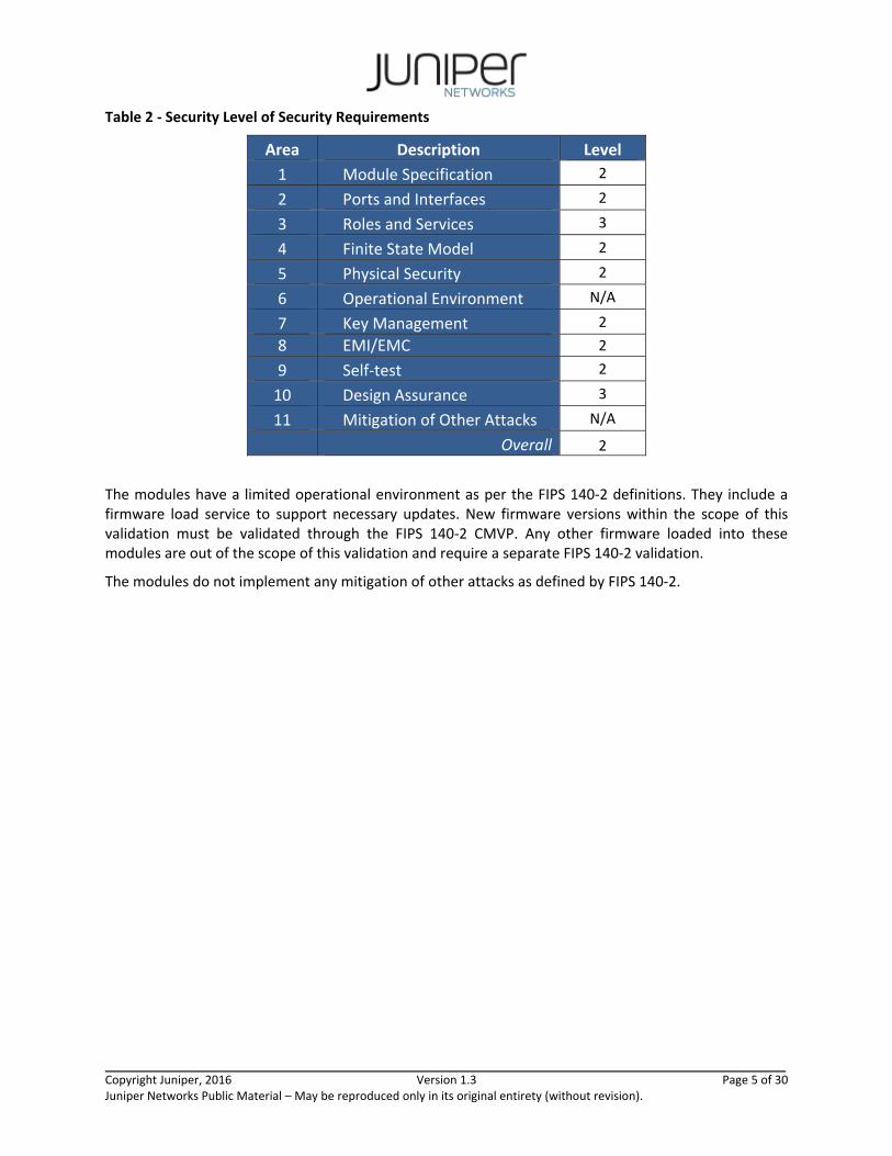
Table 2 ‐ Security Level of Security Requirements
Area Description Level
1 Module Specification 2
2 Ports and Interfaces 2
3 Roles and Services 3
4 Finite State Model 2
5 Physical Security 2
6 Operational Environment N/A
7 Key Management 2
8 EMI/EMC 2
9 Self‐test 2
10 Design Assurance 3
11 Mitigation of Other Attacks N/A
Overall 2
The modules have a limited operational environment as per the FIPS 140‐2 definitions. They include a firmware load service to support necessary updates. New firmware versions within the scope of this validation must be validated through the FIPS 140‐2 CMVP. Any other firmware loaded into these modules are out of the scope of this validation and require a separate FIPS 140‐2 validation.
The modules do not implement any mitigation of other attacks as defined by FIPS 140‐2.

Copyright Juniper, 2016 Version 1.3 Page 6 of 30 Juniper Networks Public Material – May be reproduced only in its original entirety (without revision).
1.1 Hardware and Physical Cryptographic Boundary
The physical forms of the module’s various models are depicted in Figures 1‐15 below. For all models the cryptographic boundary is defined as the outer edge of the chassis. The SRX1400 excludes the SRX1K‐NPC‐SPC‐1‐10‐40 from the requirements of FIPS 140‐2 as described in Section 5.2. The module does not rely on external devices for input and output.
Figure 1 – SRX1400 Front View
Figure 2 – SRX1400 Bottom View
Figure 3 ‐ SRX1400 Left View

Copyright Juniper, 2016 Version 1.3 Page 7 of 30 Juniper Networks Public Material – May be reproduced only in its original entirety (without revision).
Figure 4 ‐ SRX1400 Right View
Figure 5 ‐ SRX1K‐NPC‐SPC‐1‐10‐40 (Excluded Component)

Copyright Juniper, 2016 Version 1.3 Page 8 of 30 Juniper Networks Public Material – May be reproduced only in its original entirety (without revision).
Figure 6 – SRX3400 Top View
Figure 7 – SRX3400 Bottom View
Copyright Juniper, 2016 Version 1.3 Page 9 of 30 Juniper Networks Public Material – May be reproduced only in its original entirety (without revision).
Figure 8 – SRX3600 Top View
Figure 9 – SRX3600 Bottom View
Copyright Juniper, 2016 Version 1.3 Page 10 of 30 Juniper Networks Public Material – May be reproduced only in its original entirety (without revision).
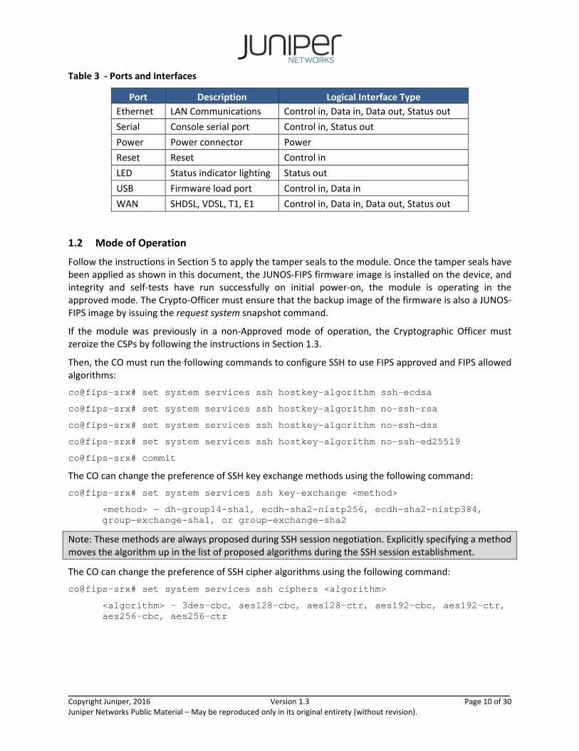
Table 3 ‐ Ports and Interfaces
Port Description Logical Interface Type
Ethernet LAN Communications Control in, Data in, Data out, Status out
Serial Console serial port Control in, Status out
Power Power connector Power
Reset Reset Control in
LED Status indicator lighting Status out
USB Firmware load port Control in, Data in
WAN SHDSL, VDSL, T1, E1 Control in, Data in, Data out, Status out
1.2 Mode of Operation
Follow the instructions in Section 5 to apply the tamper seals to the module. Once the tamper seals have been applied as shown in this document, the JUNOS‐FIPS firmware image is installed on the device, and integrity and self‐tests have run successfully on initial power‐on, the module is operating in the approved mode. The Crypto‐Officer must ensure that the backup image of the firmware is also a JUNOS‐FIPS image by issuing the request system snapshot command.
If the module was previously in a non‐Approved mode of operation, the Cryptographic Officer must zeroize the CSPs by following the instructions in Section 1.3.
Then, the CO must run the following commands to configure SSH to use FIPS approved and FIPS allowed algorithms:
co@fips-srx# set system services ssh hostkey-algorithm ssh-ecdsa
co@fips-srx# set system services ssh hostkey-algorithm no-ssh-rsa
co@fips-srx# set system services ssh hostkey-algorithm no-ssh-dss
co@fips-srx# set system services ssh hostkey-algorithm no-ssh-ed25519
co@fips-srx# commit
The CO can change the preference of SSH key exchange methods using the following command:
co@fips-srx# set system services ssh key-exchange <method>
<method> - dh-group14-sha1, ecdh-sha2-nistp256, ecdh-sha2-nistp384, group-exchange-sha1, or group-exchange-sha2
Note: These methods are always proposed during SSH session negotiation. Explicitly specifying a method moves the algorithm up in the list of proposed algorithms during the SSH session establishment.
The CO can change the preference of SSH cipher algorithms using the following command:
co@fips-srx# set system services ssh ciphers <algorithm>
<algorithm> - 3des-cbc, aes128-cbc, aes128-ctr, aes192-cbc, aes192-ctr, aes256-cbc, aes256-ctr

Copyright Juniper, 2016 Version 1.3 Page 11 of 30 Juniper Networks Public Material – May be reproduced only in its original entirety (without revision).
Note: These algorithms are always proposed during SSH session negotiation. Explicitly specifying an algorithm moves the algorithm up in the list of proposed algorithms during the SSH session establishment.
The CO can change the preference of SSH MAC algorithms or enable additional Approved algorithms using the following command:
co@fips-srx# set system services ssh macs <algorithm>
<algorithm> - hmac-sha1, hmac-sha1-96, hmac-sha2-256, hmac-sha2-512, [email protected], [email protected], [email protected], [email protected]
Note: hmac‐sha1 and hmac‐sha1‐96 are always proposed during SSH session negotiation. Explicitly specifying either algorithm moves it up in the list of proposed algorithms during the SSH session establishment. Specifying any other MAC algorithm adds it to the list of algorithms proposed.
For each IPsec tunnel configured, the CO must run the following command to configure the algorithms:
co@fips-srx# set system security ipsec <name> authentication-algorithm <algorithm>
<algorithm> - hmac-sha-256-128, hmac-sha1-96
co@fips-srx# set system security ipsec <name> encryption-algorithm <algorithm>
<algorithm> - 3des-cbc, aes-128-cbc aes-192-cbc, aes-256-cbc
The “show version” command will indicate if the module is operating in FIPS mode (e.g. JUNOS Software Release [12.1X46‐D40] (FIPS edition)), run “show system services ssh”, and run “show security ipsec” to verify that only the FIPS approved and FIPS allowed algorithms are configured for SSH and IPsec as specified above.
1.3 Firmware Load
The cryptographic module implements a firmware load service which allows the loading of legacy firmware (legacy‐use of digital signature verification using SHA‐1 as defined by SP800‐131Ar1). To comply with SP 800‐131Ar1, the Crypto Officer must manually determine when a legacy firmware load is being performed and determine if the correct type of signature is being verified.
Warning: Legacy firmware might not be FIPS 140‐2 Validated or meet SP 800‐131Ar1 requirements. The Crypto Officer must determine whether legacy firmware meets their organization’s compliance and certification requirements.
When newer firmware is being loaded, the Crypto Officer must verify the presence of an ECDSA signature for the junos and junos‐boot portions of the image by running:
% tar ztf <firmware_image>.tgz | grep esig
The Crypto Officer must verify the output show presence of an esig file for both the junos and junos‐boot portions of the image. For example:
% tar ztf junos-srx1k3k-12.1X46-D40.4-fips.tgz | grep esig
junos-boot-srx1k3k-12.1X46-D40.4-fips.esig
junos-srx1k3k-12.1X46-D40.4-fips.esig
If the two esig files are not present, the Crypto Officer must not install the image.
Copyright Juniper, 2016 Version 1.3 Page 12 of 30 Juniper Networks Public Material – May be reproduced only in its original entirety (without revision).
If the two esig files are present or the Crypto Officer is installing a legacy image, installation may continue using the following command:
co@fips-srx> request system software add [no-validate] [no-copy] <firmware_image>.tgz [reboot]
The module will automatically verify that the image signature(s) are valid.
1.4 Zeroization
The cryptographic module provides a non‐Approved mode of operation in which non‐approved cryptographic algorithms are supported. When transitioning between the non‐Approved mode of operation and the Approved mode of operation, the Cryptographic Officer must run the following commands to zeroize the Approved mode CSPs:
co@fips-srx> start shell
co@fips-srx% rm –P <keyfile>
<keyfile> - each persistent private or secret key other than the SSH host keys and the X.509 keys for IKE.
co@fips-srx% rm –P /var/db/certs/common/certificate-request/*
co@fips-srx% exit
co@fips-srx> request system zeroize
Note: The Cryptographic Officer must retain control of the module while zeroization is in process.

Copyright Juniper, 2016 Version 1.3 Page 13 of 30 Juniper Networks Public Material – May be reproduced only in its original entirety (without revision).
2 Cryptographic Functionality
The module implements the FIPS Approved and Non‐Approved but Allowed cryptographic functions listed in the tables below. Table 6 summarizes the high level protocol algorithm support. The module does not implement algorithms that require vendor affirmation.
Table 4 ‐ Approved and CAVP Validated Cryptographic Functions
Implementation Reference Mode Functions Strength Cert
IPsec Triple‐DES SP 800‐20 TCBC Encrypt and decrypt 112 (3‐Key) 2038
IPsec AES FIPS 197 SP 800‐38A
CBC Encrypt and decrypt 128, 192, 256 3663
IPsec SHA FIPS 180‐4
Hash generation 80 (SHA‐1)
128 (SHA‐256) 3081
IPsec HMAC FIPS 198‐1 HMAC Gen, Ver 128 (HMAC‐SHA‐1) 256 (HMAC‐SHA‐
256) 2413
IKE Triple‐DES SP 800‐20 TCBC Encrypt and decrypt 112 2035
IKE AES FIPS 197 SP 800‐38A
CBC Encrypt and decrypt 128, 192, 256 3656
IKE SHA FIPS 180‐4
Hash generation 80 (SHA‐1)
128 (SHA‐256) 192 (SHA‐384)
3074
IKE HMAC FIPS 198‐1
HMAC Gen, Ver
128 (HMAC‐SHA‐1) 256 (HMAC‐SHA‐256, HMAC‐SHA‐
384)
2406
IKE KDF SP 800‐135 IKE v1/v2 KDF 112‐256 659
IKE ECDSA FIPS 186‐4
KeyGen, SigGen, SigVer 128 (P‐256) 192 (P‐384)
770
IKE RSA FIPS 186‐4 SigGen, SigVer 112 (2048 bit) 1896
IKE DSA FIPS 186‐4 KeyGen 112 (2048 bit) 1033
SSH Triple‐DES SP 800‐20 TCBC Encrypt and decrypt 112 (3‐Key) 2036
SSH AES FIPS 197 SP 800‐38A
CBC CTR
Encrypt and decrypt 128, 192, 256 3650
SSH SHA FIPS 180‐4
Hash generation 80 (SHA‐1)
128 (SHA‐256) 256 (SHA‐512)
3068
SSH HMAC FIPS 198‐1 HMAC Gen, Ver
128 (HMAC‐SHA‐1) 256 (HMAC‐SHA‐256, HMAC‐SHA‐
512)
2400
SSH RSA FIPS 186‐4 KeyGen, SigVer 112 (2048 bit)
1885 SigVer 128 (3072 bit)
SSH ECDSA FIPS 186‐4 KeyGen, SigGen, SigVer 112 (P‐224) 128 (P‐256) 192 (P‐384)
758
Copyright Juniper, 2016 Version 1.3 Page 14 of 30 Juniper Networks Public Material – May be reproduced only in its original entirety (without revision).
SSH DSA FIPS 186‐4 KeyGen 112 (2048 bit) 1022
DRBG SP 800‐90A HMAC Random generation 256 (HMAC‐SHA‐
256) 981
SSH KDF SP 800‐135 SSHv2 KDF 112‐256 660
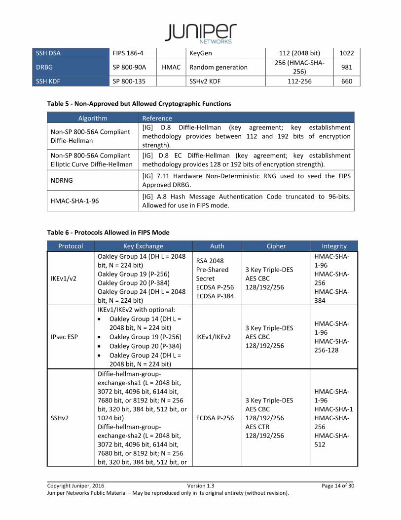
Table 5 ‐ Non‐Approved but Allowed Cryptographic Functions
Algorithm Reference
Non‐SP 800‐56A Compliant Diffie‐Hellman
[IG] D.8 Diffie‐Hellman (key agreement; key establishment methodology provides between 112 and 192 bits of encryption strength).
Non‐SP 800‐56A Compliant Elliptic Curve Diffie‐Hellman
[IG] D.8 EC Diffie‐Hellman (key agreement; key establishment methodology provides 128 or 192 bits of encryption strength).
NDRNG [IG] 7.11 Hardware Non‐Deterministic RNG used to seed the FIPS Approved DRBG.
HMAC‐SHA‐1‐96 [IG] A.8 Hash Message Authentication Code truncated to 96‐bits. Allowed for use in FIPS mode.
Table 6 ‐ Protocols Allowed in FIPS Mode
Protocol Key Exchange Auth Cipher Integrity
IKEv1/v2
Oakley Group 14 (DH L = 2048 bit, N = 224 bit) Oakley Group 19 (P‐256) Oakley Group 20 (P‐384) Oakley Group 24 (DH L = 2048 bit, N = 224 bit)
RSA 2048 Pre‐Shared Secret ECDSA P‐256 ECDSA P‐384
3 Key Triple‐DES AES CBC 128/192/256
HMAC‐SHA‐1‐96 HMAC‐SHA‐256 HMAC‐SHA‐384
IPsec ESP
IKEv1/IKEv2 with optional:
Oakley Group 14 (DH L = 2048 bit, N = 224 bit)
Oakley Group 19 (P‐256)
Oakley Group 20 (P‐384)
Oakley Group 24 (DH L = 2048 bit, N = 224 bit)
IKEv1/IKEv2 3 Key Triple‐DES AES CBC 128/192/256
HMAC‐SHA‐1‐96 HMAC‐SHA‐256‐128
SSHv2
Diffie‐hellman‐group‐exchange‐sha1 (L = 2048 bit, 3072 bit, 4096 bit, 6144 bit, 7680 bit, or 8192 bit; N = 256 bit, 320 bit, 384 bit, 512 bit, or 1024 bit) Diffie‐hellman‐group‐exchange‐sha2 (L = 2048 bit, 3072 bit, 4096 bit, 6144 bit, 7680 bit, or 8192 bit; N = 256 bit, 320 bit, 384 bit, 512 bit, or
ECDSA P‐256
3 Key Triple‐DES AES CBC 128/192/256 AES CTR 128/192/256
HMAC‐SHA‐1‐96 HMAC‐SHA‐1HMAC‐SHA‐256 HMAC‐SHA‐512

Copyright Juniper, 2016 Version 1.3 Page 15 of 30 Juniper Networks Public Material – May be reproduced only in its original entirety (without revision).
1024 bit) Diffie‐hellman‐group14‐sha1 (L = 2048 bit; N = 256 bit, 320 bit, 384 bit, 512 bit, or 1024 bit) ECDH‐sha2‐nistp256 ECDH‐sha2‐nistp384
These protocols have not been reviewed or tested by the CAVP and CMVP.
The IKE and SSH algorithms allow independent selection of key exchange, authentication, cipher and integrity. In Table 6 above, each column of options for a given protocol is independent, and may be used in any viable combination.
2.1 Disallowed Algorithms
These algorithms are non‐Approved algorithms that are disabled when the module is operated in an Approved mode of operation. These security functions are available in the SSH connect (non‐compliant) service.
ssh‐dss (DSA non‐compliant)
dh‐group1‐sha1 (Diffie‐Hellman (non‐compliant key agreement; key establishment methodology provides less than 112 bits of encryption strength)
hmac‐md5
hmac‐md5‐96
hmac‐md5‐96‐[email protected]
hmac‐md5‐[email protected]
hmac‐ripemd160
hmac‐ripemd160‐[email protected]
umac‐128‐[email protected]
umac‐64‐[email protected]
umac‐[email protected]
arcfour
arcfour128
arcfour256
blowfish‐cbc
cast128‐cbc
2.2 Critical Security Parameters
All CSPs and public keys used by the module are described in this section.
Table 7 ‐ Critical Security Parameters (CSPs)
Name Description and usage
DRBG_Seed Seed material used to seed or reseed the DRBG
DRBG_State V and Key values for the HMAC_DRBG
SSH PHK SSH Private host key. 1st time SSH is configured, the keys are generated. ECDSA P‐256. Used to identify the host.

Copyright Juniper, 2016 Version 1.3 Page 16 of 30 Juniper Networks Public Material – May be reproduced only in its original entirety (without revision).
SSH DH SSH Diffie‐Hellman private component. Ephemeral Diffie‐Hellman private key used in SSH. DH (N = 256 bit, 320 bit, 384 bit, 512 bit, or 1024 bit1), ECDH P‐256, or ECDH P‐384
SSH‐SEK SSH Session Key; Session keys used with SSH. TDES (3key), AES, HMAC.
ESP‐SEK IPSec ESP Session Keys. TDES (3 key), AES, HMAC.
IKE‐PSK Pre‐Shared Key used to authenticate IKE connections.
IKE‐Priv IKE Private Key. RSA 2048, ECDSA P‐256, or ECDSA P‐384
IKE‐SKEYID IKE SKEYID. IKE secret used to derive IKE and IPsec ESP session keys.
IKE‐SEK IKE Session Keys. TDES (3 key), AES, HMAC.
IKE‐DH‐PRI IKE Diffie‐Hellman private component. Ephemeral Diffie‐Hellman private key used in IKE. DH N = 224 bit, ECDH P‐256, or ECDH P‐384
CO‐PW ASCII Text used to authenticate the CO.
User‐PW ASCII Text used to authenticate the User.
Table 8 ‐ Public Keys
Name Description and usage
SSH‐PUB SSH Public Host Key used to identify the host. ECDSA P‐256.
SSH‐DH‐PUB Diffie‐Hellman public component. Ephemeral Diffie‐Hellman public key used in SSH key establishment. DH (L = 2048 bit, 3072 bit, 4096 bit, 6144 bit, 7680 bit, or 8192 bit), ECDH P‐256, or ECDH P‐384
IKE‐PUB IKE Public Key RSA 2048, ECDSA P‐256, or ECDSA P‐384
IKE‐DH‐PUB Diffie‐Hellman public component. Ephemeral Diffie‐Hellman public key used in IKE key establishment. DH L = 2048 bit, ECDH P‐256, or ECDH P‐384
Auth‐UPub User Authentication Public Keys. Used to authenticate users to the module. ECDSA P256 or P‐384
Auth‐COPub CO Authentication Public Keys. Used to authenticate CO to the module. ECDSA P256 or P‐384
Root‐CA JuniperRootCA. RSA 2048 X.509 Certificate; Used to verify the validity of the Juniper Package‐CA at software load.
RootEC CA JuniperRootEC CA. ECDSA P‐256 X.509 Certificate; Used to verify the validity of the Juniper Package CA at software load and also at runtime for integrity.
Package‐CA PackageCA. RSA 2048 X.509 Certificate; Used to verify the validity of legacy Juniper Images at software load.
PackageEC CA
PackageEC CA. ECDSA P‐256 X.509 Certificate; Used to verify the validity the Juniper Image at software load and also at runtime for integrity.
1 SSH generates a Diffie‐Hellman private key that is 2x the bit length of the longest symmetric or MAC key negotiated.

Copyright Juniper, 2016 Version 1.3 Page 17 of 30 Juniper Networks Public Material – May be reproduced only in its original entirety (without revision).
3 Roles, Authentication and Services
3.1 Roles and Authentication of Operators to Roles
The module supports two roles: Cryptographic Officer (CO) and User. The module supports concurrent operators, but does not support a maintenance role and/or bypass capability. The module enforces the separation of roles using either identity‐based operator authentication.
The Cryptographic Officer role configures and monitors the module via a console or SSH connection. As root or super‐user, the Cryptographic Officer has permission to view and edit secrets within the module.
The User role monitors the router via the console or SSH. The user role may not change the configuration.
3.2 Authentication Methods
The module implements two forms of Identity‐Based authentication, Username and password over the Console and SSH as well as Username and public key over SSH.
Password authentication: The module enforces 10‐character passwords (at minimum) chosen from the 96 human readable ASCII characters. The maximum password length is 20‐characters.
The module enforces a timed access mechanism as follows: For the first two failed attempts (assuming 0 time to process), no timed access is enforced. Upon the third attempt, the module enforces a 5‐second delay. Each failed attempt thereafter results in an additional 5‐second delay above the previous (e.g. 4th failed attempt = 10‐second delay, 5th failed attempt = 15‐second delay, 6th failed attempt = 20‐second delay, 7th failed attempt = 25‐second delay).
This leads to a maximum of seven (7) possible attempts in a one‐minute period for each getty. The best approach for the attacker would be to disconnect after 4 failed attempts, and wait for a new getty to be spawned. This would allow the attacker to perform roughly 9.6 attempts per minute (576 attempts per hour/60 mins); this would be rounded down to 9 per minute, because there is no such thing as 0.6 attempts. Thus the probability of a successful random attempt is 1/9610, which is less than 1/1 million. The probability of a success with multiple consecutive attempts in a one‐minute period is 9/(9610), which is less than 1/100,000.
ECDSA signature verification: SSH public‐key authentication. Processing constraints allow for a maximum of 5.6e7 ECDSA attempts per minute. The module supports ECDSA (P‐256 and P‐384). The probability of a success with multiple consecutive attempts in a one‐minute period is 5.6e7/(2128).
3.3 Services
All services implemented by the module are listed in the tables below. Table 11 lists the access to CSPs by each service.
Table 9 ‐ Authenticated Services
Service Description CO User
Configure security
Security relevant configuration x
Configure Non‐security relevant configuration x
Secure Traffic IPsec protected connection (ESP) x
Status Show status x x
Zeroize Destroy all CSPs x

Copyright Juniper, 2016 Version 1.3 Page 18 of 30 Juniper Networks Public Material – May be reproduced only in its original entirety (without revision).
SSH connect Initiate SSH connection for SSH monitoring and control (CLI)
x x
IPsec connect Initiate IPsec connection (IKE) x
Console access Console monitoring and control (CLI) x x
Remote reset Software initiated reset x
Table 10 ‐ Unauthenticated traffic
Service Description
Local reset Hardware reset or power cycle
Traffic Traffic requiring no cryptographic services
Table 11 ‐ CSP Access Rights within Services
Service
CSPs
DRBG_Seed
DRBG_State
SSH PHK
SSH DH
SSH‐SEK
ESP‐SEK
IKE‐PSK
IKE‐Priv
IKE‐SKEYI
IKE‐SEK
IKE‐DH‐PRI
CO‐PW
User‐PW
Configure security ‐‐ E GW ‐‐ ‐‐ ‐‐ W GW ‐‐ ‐‐ ‐‐ W W
Configure ‐‐ ‐‐ ‐‐ ‐‐ ‐‐ ‐‐ ‐‐ ‐‐ ‐‐ ‐‐ ‐‐ ‐‐ ‐‐
Secure traffic ‐‐ ‐‐ ‐‐ ‐‐ ‐‐ E ‐‐ ‐‐ ‐‐ E ‐‐ ‐‐ ‐‐
Status ‐‐ ‐‐ ‐‐ ‐‐ ‐‐ ‐‐ ‐‐ ‐‐ ‐‐ ‐‐ ‐‐ ‐‐ ‐‐
Zeroize ‐‐ Z Z ‐‐ ‐‐ ‐‐ Z Z ‐‐ ‐‐ ‐‐ Z Z
SSH connect ‐‐ E E GE GE ‐‐ ‐‐ ‐‐ ‐‐ ‐‐ ‐‐ E E
IPsec connect ‐‐ E ‐‐ ‐‐ ‐‐ G E E G G G ‐‐ ‐‐
Console access ‐‐ ‐‐ ‐‐ ‐‐ ‐‐ ‐‐ ‐‐ ‐‐ ‐‐ ‐‐ ‐‐ E E
Remote reset GE G ‐‐ Z Z Z ‐‐ ‐‐ Z Z Z Z Z
Local reset GE G ‐‐ Z Z Z ‐‐ ‐‐ Z Z Z Z Z
Traffic ‐‐ ‐‐ ‐‐ ‐‐ ‐‐ ‐‐ ‐‐ ‐‐ ‐‐ ‐‐ ‐‐ ‐‐ ‐‐
G = Generate: The module generates the CSP R = Read: The CSP is read from the module (e.g. the CSP is output) E = Execute: The module executes using the CSP W = Write: The CSP is updated or written to the module Z = Zeroize: The module zeroizes the CSP. The non‐approved algorithms are available for use with the Approved services when the module is in the non‐approved mode of operation.

Copyright Juniper, 2016 Version 1.3 Page 19 of 30 Juniper Networks Public Material – May be reproduced only in its original entirety (without revision).
3.4 Non‐Approved Services
The following services are available in the non‐Approved mode of operation. The security functions provided by the non‐Approved services are identical to the Approved counterparts with the exception of SSH Connect (non‐compliant). SSH Connect (non‐compliant) supports the security functions identified in Section 2.1 and the SSHv2 row of Table 6.
Table 12 ‐ Authenticated Services
Service Description CO User
Configure security (non‐compliant)
Security relevant configuration x
Configure (non‐compliant) Non‐security relevant configuration x
Secure Traffic (non‐compliant)
IPsec protected connection (ESP) x
Status (non‐compliant) Show status x x
Zeroize (non‐compliant) Destroy all CSPs x
SSH connect (non‐compliant)
Initiate SSH connection for SSH monitoring and control (CLI)
x x
IPsec connect (non‐compliant)
Initiate IPsec connection (IKE) x
Console access (non‐compliant)
Console monitoring and control (CLI) x x
Remote reset (non‐compliant)
Software initiated reset x
Table 13 ‐ Unauthenticated traffic
Service Description
Local reset (non‐compliant)
Hardware reset or power cycle
Traffic (non‐compliant)
Traffic requiring no cryptographic services

Copyright Juniper, 2016 Version 1.3 Page 20 of 30 Juniper Networks Public Material – May be reproduced only in its original entirety (without revision).
4 Self‐tests
Each time the module is powered up it tests that the cryptographic algorithms still operate correctly and that sensitive data have not been damaged. Power‐up self–tests are available on demand by power cycling the module.
On power up or reset, the module performs the self‐tests described below. All KATs must be completed successfully prior to any other use of cryptography by the module. If one of the KATs fails, the module enters the Critical Failure error state.
The module performs the following power‐up self‐tests:
Firmware Integrity check using ECDSA P‐256 with SHA‐256
QuickSec JSF Hardware Accelerated KATs o AES‐CBC Encrypt KAT o AES‐CBC Decrypt KAT o RSA 2048 w/ SHA‐256 Sign KAT o RSA 2048 w/ SHA‐256 Verify KAT o ECDSA P‐256 w/ SHA‐256 Sign/Verify PCT
QuickSec Hardware Accelerated KATs o Triple‐DES‐CBC Encrypt KAT o Triple‐DES‐CBC Decrypt KAT o HMAC‐SHA‐1 KAT o HMAC‐SHA‐256 KAT
OpenSSL KATs o SP 800‐90A HMAC DRBG KAT
Health‐tests initialize, re‐seed, and generate. o ECDSA P‐256 Sign/Verify PCT o ECDH P‐256 KAT
Derivation of the expected shared secret. o RSA 2048 w/ SHA‐256 Sign KAT o RSA 2048 w/ SHA‐256 Verify KAT o Triple‐DES‐CBC Encrypt KAT o Triple‐DES‐CBC Decrypt KAT o HMAC‐SHA‐1 KAT o HMAC‐SHA‐256 KAT o HMAC‐SHA‐384 KAT o HMAC‐SHA‐512 KAT o SHA‐256 KAT o AES‐CBC Encrypt KAT o ASE‐CBC Decrypt KAT o KDF‐SSH KAT
QuickSec KATs o Triple‐DES‐CBC Encrypt KAT o Triple‐DES Decrypt KAT o HMAC‐SHA1 KAT o HMAC‐SHA‐256 KAT o HMAC‐SHA‐384 KAT o AES‐CBC Encrypt KAT

Copyright Juniper, 2016 Version 1.3 Page 21 of 30 Juniper Networks Public Material – May be reproduced only in its original entirety (without revision).
o ASE‐CBC Decrypt KAT o KDF‐IKE‐V1 KAT o KDF‐IKE‐V2 KAT
Critical Function Test
o The cryptographic module performs a verification of a limited operational environment, and verification of optional non‐critical packages.
The module also performs the following conditional self‐tests:
Continuous RNG Test on the SP 800‐90A HMAC‐DRBG
Continuous RNG test on the NDRNG
Pairwise consistency test when generating DSA, ECDSA, and RSA key pairs.
Firmware Load Test (ECDSA or RSA signature verification)

Copyright Juniper, 2016 Version 1.3 Page 22 of 30 Juniper Networks Public Material – May be reproduced only in its original entirety (without revision).
5 Physical Security Policy
The modules physical embodiment is that of a multi‐chip standalone device that meets Level 2 Physical Security requirements. The module is completely enclosed in a rectangular nickel or clear zinc coated, cold rolled steel, plated steel and brushed aluminum enclosure. There are no ventilation holes, gaps, slits, cracks, slots, or crevices that would allow for any sort of observation of any component contained within the cryptographic boundary. Tamper‐evident seals allow the operator to tell if the enclosure has been breached. These seals are not factory‐installed and must be applied by the Cryptographic Officer. (Seals are available for order from Juniper using part number JNPR‐FIPS‐TAMPER‐LBLS.) The tamper‐evident seals shall be installed for the module to operate in a FIPS mode of operation.
The Cryptographic Officer is responsible for securing and having control at all times of any unused seals and the direct control and observation of any changes to the module such as reconfigurations where the tamper‐evident seals or security appliances are removed or installed to ensure the security of the module is maintained during such changes and the module is returned to a FIPS Approved state.
Table 14 – Physical Security Inspection Guidelines
Physical Security Mechanism
Recommended Frequency of Inspection/Test
Inspection/Test Guidance Details
Tamper seals, opaque metal enclosure.
Once per month by the Cryptographic Officer.
Seals should be free of any tamper evidence.
5.1 General Tamper Seal Placement and Application Instructions
For all seal applications, the Cryptographic Officer should observe the following instructions:
Handle the seals with care. Do not touch the adhesive side.
Before applying a seal, ensure the location of application is clean, dry, and clear of any residue.
Place the seal on the module, applying firm pressure across it to ensure adhesion. Allow at least 1 hour for the adhesive to cure.
5.2 SRX1400 (16 seals)
When using the SRX1k3k‐2CFM‐TRAY in slots 1 and 3, a SRX3k‐SPC‐1‐10‐40 may not be installed in slot 3. The SPC(s) may only be installed in slots 1 and/or 2.
An NPC installed in slot 3 is considered non‐security relevant and excluded from the requirements of FIPS 140‐2. It does not perform cryptography and a malfunction cannot cause other components to malfunction, disclose CSPs, or output plaintext data.
Tamper‐evident seals must be applied to the following locations:
The front of the module: o Four seals, horizontal, sticking to the far left sub‐pane and one of the three adjacent
sub‐panes. The bottom two sub‐panes should have one seal each, while the top one should have two.
o One seal, vertical, spanning the three sub‐panes adjacent to the far‐left sub‐pane. Should go about 1cm to the left of the nearby RJ45 jack (labelled “AUX”).
o One seal, vertical, applied around 3‐5cm to the left of the power input. Should wrap around and stick to the bottom pane.
o One seal, vertical, on the top sub‐pane. Should be in the vicinity of the “CONSOLE” RJ45 jack, and extend to the middle‐right sub‐pane and the top pane.

Copyright Juniper, 2016 Version 1.3 Page 23 of 30 Juniper Networks Public Material – May be reproduced only in its original entirety (without revision).
o One seal, horizontal, sticking to both middle panes (the ones with RJ45 jacks). o Two seals, vertical, on the two bottom‐right sub‐panes. One should be immediately to
the right of the power input, and the other layed across the blank far‐right‐bottom sub‐pane. Both should stick to the bottom pane.
o Three seals, horizontal. Two stick to the top‐right sub‐pane, the other to the middle‐right sub‐pane. All three should wrap around and stick to the right of the module.
One the right side of the module, ensure there are three seals wrapping around from the front of the module.
The rear of the module: o Two seals, vertical, above and below the screw‐hole on the right‐ish side of the module.
The upper one should touch the top pane; the lower one should touch the bottom pane.
No seals needed on the left side of the module.
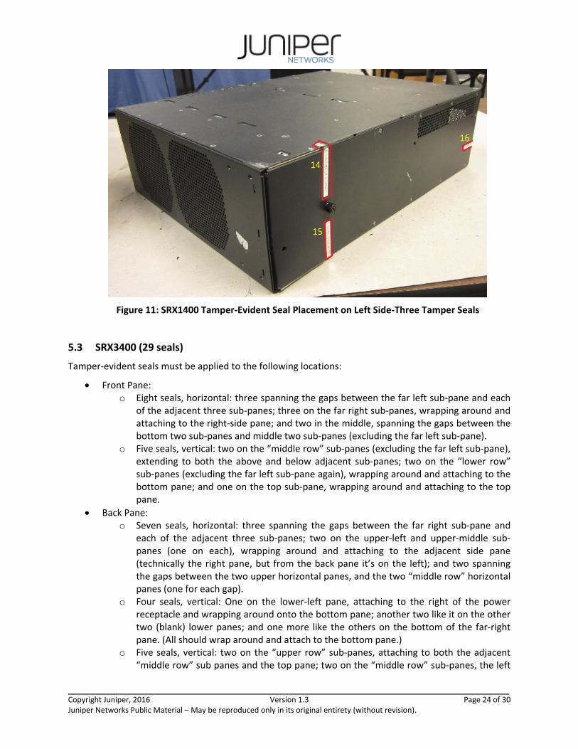
Figure 10: SRX1400 Tamper‐Evident Seal Placement on Front & Right Side‐13 Tamper Seals
Copyright Juniper, 2016 Version 1.3 Page 24 of 30 Juniper Networks Public Material – May be reproduced only in its original entirety (without revision).
Figure 11: SRX1400 Tamper‐Evident Seal Placement on Left Side‐Three Tamper Seals
5.3 SRX3400 (29 seals)
Tamper‐evident seals must be applied to the following locations:
Front Pane: o Eight seals, horizontal: three spanning the gaps between the far left sub‐pane and each
of the adjacent three sub‐panes; three on the far right sub‐panes, wrapping around and attaching to the right‐side pane; and two in the middle, spanning the gaps between the bottom two sub‐panes and middle two sub‐panes (excluding the far left sub‐pane).
o Five seals, vertical: two on the “middle row” sub‐panes (excluding the far left sub‐pane), extending to both the above and below adjacent sub‐panes; two on the “lower row” sub‐panes (excluding the far left sub‐pane again), wrapping around and attaching to the bottom pane; and one on the top sub‐pane, wrapping around and attaching to the top pane.
Back Pane: o Seven seals, horizontal: three spanning the gaps between the far right sub‐pane and
each of the adjacent three sub‐panes; two on the upper‐left and upper‐middle sub‐panes (one on each), wrapping around and attaching to the adjacent side pane (technically the right pane, but from the back pane it’s on the left); and two spanning the gaps between the two upper horizontal panes, and the two “middle row” horizontal panes (one for each gap).
o Four seals, vertical: One on the lower‐left pane, attaching to the right of the power receptacle and wrapping around onto the bottom pane; another two like it on the other two (blank) lower panes; and one more like the others on the bottom of the far‐right pane. (All should wrap around and attach to the bottom pane.)
o Five seals, vertical: two on the “upper row” sub‐panes, attaching to both the adjacent “middle row” sub panes and the top pane; two on the “middle row” sub‐panes, the left
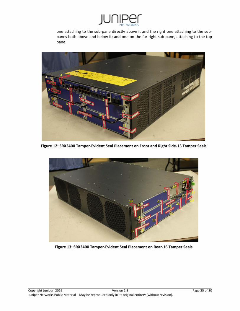
Copyright Juniper, 2016 Version 1.3 Page 25 of 30 Juniper Networks Public Material – May be reproduced only in its original entirety (without revision).
one attaching to the sub‐pane directly above it and the right one attaching to the sub‐panes both above and below it; and one on the far right sub‐pane, attaching to the top pane.
Figure 12: SRX3400 Tamper‐Evident Seal Placement on Front and Right Side‐13 Tamper Seals
Figure 13: SRX3400 Tamper‐Evident Seal Placement on Rear‐16 Tamper Seals

Copyright Juniper, 2016 Version 1.3 Page 26 of 30 Juniper Networks Public Material – May be reproduced only in its original entirety (without revision).
5.4 SRX3600 (35 seals)
Tamper‐evident seals must be applied to the following locations:
Front Pane: o Ten seals, horizontal: five on the far left sub‐pane, attaching to each of the adjacent sub‐
panes (one on each); five on the rightmost edges of the sub‐panes touching the right edge (one on each), wrapping around and attaching to the right pane.
o Eight seals, vertical: One on each of the horizontal sub‐panes, attaching to the sub‐panes immediately above and below it. The bottom‐most sub‐panes should have their seals wrap around and attach to the bottom pane, same for the top‐most sub pane and the top pane. For the sub‐pane with the various jacks/receptacles, the seal should be to the left of all the RJ45 jacks.
Back Pane: o Nine seals, horizontal: these are divided between the “middle three rows”, with three
seals for each – one between the two horizontal sub‐panes, one on the left sub‐pane wrapping around and attaching to the (relative) left pane, and one on the right horizontal sub‐pane attaching to the far‐right pane.
o Three seals, vertical: one on each of the lowermost sub‐panes (including the far right pane), all wrapping around and attaching to the bottom pane.
o Five seals, vertical: one on each of the uppermost sub‐panes (including the far right pane once more), all wrapping around and touching the top pane. (The power receptacles are each on their own pane.)
Figure 14: SRX3600 Tamper‐Evident Seal Placement on Front and Right Side‐18 Tamper Seals
Copyright Juniper, 2016 Version 1.3 Page 27 of 30 Juniper Networks Public Material – May be reproduced only in its original entirety (without revision).
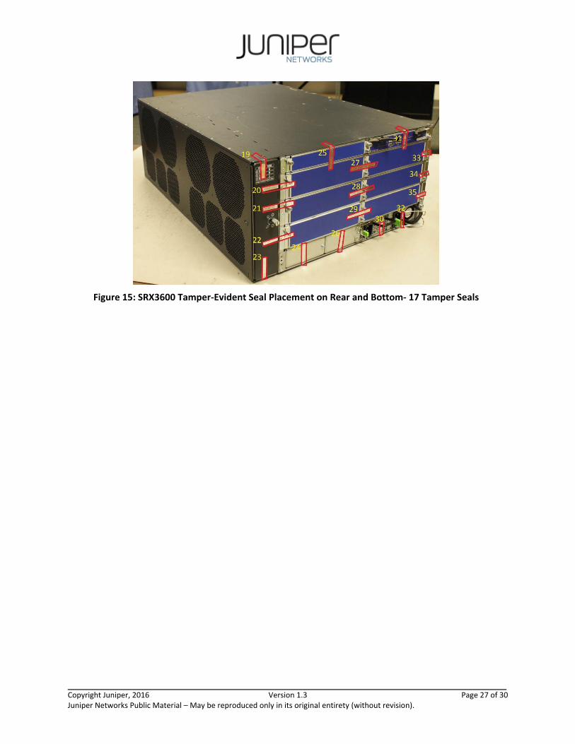
Figure 15: SRX3600 Tamper‐Evident Seal Placement on Rear and Bottom‐ 17 Tamper Seals

Copyright Juniper, 2016 Version 1.3 Page 28 of 30 Juniper Networks Public Material – May be reproduced only in its original entirety (without revision).
6 Security Rules and Guidance
The module design corresponds to the security rules below. The term must in this context specifically refers to a requirement for correct usage of the module in the Approved mode; all other statements indicate a security rule implemented by the module.
1. The module clears previous authentications on power cycle.
2. When the module has not been placed in a valid role, the operator does not have access to any cryptographic services.
3. Power up self‐tests do not require any operator action.
4. Data output is inhibited during key generation, self‐tests, zeroization, and error states.
5. Status information does not contain CSPs or sensitive data that if misused could lead to a compromise of the module.
6. There are no restrictions on which keys or CSPs are zeroized by the zeroization service.
7. The module does not support a maintenance interface or role.
8. The module does not support manual key entry.
9. The module does not output intermediate key values.
10. The module requires two independent internal actions to be performed prior to outputing plaintext CSPs.
11. The cryptographic officer must determine whether firmware being loaded is a legacy use of the firmware load service.
12. The cryptographic officer must retain control of the module while zeroization is in process.
Copyright Juniper, 2016 Version 1.3 Page 29 of 30 Juniper Networks Public Material – May be reproduced only in its original entirety (without revision).
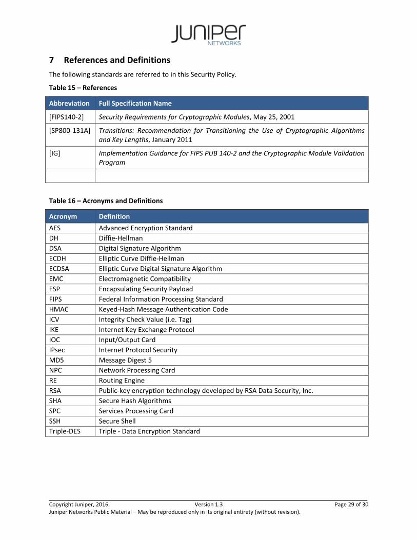
7 References and Definitions
The following standards are referred to in this Security Policy.
Table 15 – References
Abbreviation Full Specification Name
[FIPS140‐2] Security Requirements for Cryptographic Modules, May 25, 2001
[SP800‐131A] Transitions: Recommendation for Transitioning the Use of Cryptographic Algorithms and Key Lengths, January 2011
[IG] Implementation Guidance for FIPS PUB 140‐2 and the Cryptographic Module Validation Program
Table 16 – Acronyms and Definitions
Acronym Definition
AES Advanced Encryption Standard
DH Diffie‐Hellman
DSA Digital Signature Algorithm
ECDH Elliptic Curve Diffie‐Hellman
ECDSA Elliptic Curve Digital Signature Algorithm
EMC Electromagnetic Compatibility
ESP Encapsulating Security Payload
FIPS Federal Information Processing Standard
HMAC Keyed‐Hash Message Authentication Code
ICV Integrity Check Value (i.e. Tag)
IKE Internet Key Exchange Protocol
IOC Input/Output Card
IPsec Internet Protocol Security
MD5 Message Digest 5
NPC Network Processing Card
RE Routing Engine
RSA Public‐key encryption technology developed by RSA Data Security, Inc.
SHA Secure Hash Algorithms
SPC Services Processing Card
SSH Secure Shell
Triple‐DES Triple ‐ Data Encryption Standard

Copyright Juniper, 2016 Version 1.3 Page 30 of 30 Juniper Networks Public Material – May be reproduced only in its original entirety (without revision).
Table 17 – Datasheets
Model Title URL
SRX1400
SRX Series Service Gateways for small to mid size data center, enterprise, and service provider network deployments
https://www.juniper.net/assets/us/en/local/pdf/datasheets/1000336‐en.pdf
SRX3400 SRX3600
SRX Series Service Gateways for small to mid size data center, enterprise, and service provider network deployments
https://www.juniper.net/assets/us/en/local/pdf/datasheets/1000267‐en.pdf