june 2018 rosemount cco 5500 - emerson.com · the rosemount™ cco 5500 carbon monoxide (co)...
TRANSCRIPT

Reference Manual00809-0100-4550, Rev AA
June 2018
Rosemount™ CCO 5500
Carbon Monoxide (CO) Analyzer
Essential instructions
Read this page before proceeding!
EmersonTM designs, manufactures, and tests its RosemountTM products to meet many national and international standards.Because these instruments are sophisticated technical products, you must properly install, use, and maintain them to ensure theycontinue to operate within their normal specifications. The following instructions must be adhered to and integrated into yoursafety program when installing, using, and maintaining Rosemount products. Failure to follow the proper instructions may causeany one of the following situations to occur: loss of life, personal injury, property damage, damage to this instrument, and warrantyinvalidation.
• Read all instructions prior to installing, operating, and servicing this product. If this instruction manual is not the correctmanual, call 1-855-724-2638, and we will provide the requested manual. Save this manual for future reference.
• If you do not understand any of the instructions, contact your Emerson representative for clarification.
• Follow all warnings, cautions, and instructions marked on and supplied with the product.
• Inform and educate your personnel in the proper installation, operation, and maintenance of the product.
• Install your equipment as specified in the installation instructions of the appropriate manual and per applicable local andnational codes. Connect all products to the proper electrical and pressure sources.
• To ensure proper performance, use qualified personnel to install, operate, update, program, and maintain the product.
• When replacement parts are required, ensure that qualified people use replacement parts specified by Rosemount.Unauthorized parts and procedures can affect the product's performance, place the safe operation of your process at risk,and VOID YOUR WARRANTY. Look alike substitutions may result in fire, electrical hazards, or improper operation.
• Ensure that all equipment doors are closed and protective covers are in place, except when maintenance is being performedby qualified people, to prevent electrical shock and personal injury.
The information contained in this document is subject to change without notice.
Warranty
RosemountTM warrants that the equipment manufactured and sold by it will, uponshipment, be free of defects in workmanship or material. Should any failure to conform tothis warranty become apparent during a period of one year after the date of shipment,Rosemount shall, upon prompt written notice from the purchaser, correct suchnonconformity by repair or replacement, F.O.B. factory of the defective part or parts.Correction in the manner provided above shall constitute a fulfillment of all liabilities ofRosemount with respect to the quality of the equipment.
THE FOREGOING WARRANTY IS EXCLUSIVE AND IN LIEU OF ALL OTHER WARRANTIES OF QUALITY WHETHER WRITTEN, ORAL, ORIMPLIED (INCLUDING ANY WARRANTY OF MERCHANTABILITY OR FITNESS FOR PURPOSE).
The remedy(ies) provided above shall be purchase'rs sole remedy(ies) for any failure of Rosemount to comply with the warrantyprovisions, whether claims by the purchaser are based in contract or in tort (including negligence).
Rosemount does not warrant equipment against normal deterioration due to environment. Factors such as corrosive gases andsolid particulates can be detrimental and can create the need for repair or replacement as part of normal wear and tear during thewarranty period.
Equipment supplied by Rosemount but not manufactured by it will be subject to the same warranty as is extended to Rosemount bythe original manufacturer.
At the time of installation, it is important that the required services are supplied to the system and that the electronic controller isset up at least to the point where it is controlling the sensor heater. This will ensure that, should there be a delay betweeninstallation and full commissioning, the sensor being supplied with ac power and reference air will not be subjected to componentdeterioration.
Preface
The purpose of this manual is to provide information concerning the components,functions, installation, and maintenance of the RosemountTM CCO 5500.
Some sections may describe equipment not used in your configuration. Become thoroughly familiar with the operation of thismodule before operating it. Read this reference manual completely.
Definitions
The following definitions apply to WARNINGS, CAUTIONS, and NOTICES found throughoutthis publication.

WARNING!Highlights an operation or maintenance procedure, condition, statement, etc. that if not strictly observed, could result in injury,death, or long-term health hazards of personnel.
CAUTION!Highlights an operation or maintenance procedure, practice, condition, statement, etc. that if not strictly observed, could result indamage to or destruction of equipment or loss of effectiveness.
NOTICEHighlights an essential operating procedure, condition, or statement.
Symbols
:Earth (ground) terminal
:Protective conduit or terminal
:Risk of electrical shock
:Warning: Refer to Instruction Manual


Contents
Chapter 1 Description and specifications ..........................................................................................11.1 Component checklist ..................................................................................................................... 11.2 Overview ........................................................................................................................................31.3 System description .........................................................................................................................31.4 Specifications .................................................................................................................................51.5 Rosemount
™ CCO 5500 ordering information ................................................................................ 6
Chapter 2 Install ...............................................................................................................................72.1 Unpack the equipment ...................................................................................................................72.2 Safety considerations ..................................................................................................................... 72.3 Cable requirements ........................................................................................................................82.4 Selecting location ...........................................................................................................................8
2.4.1 Points to consider ............................................................................................................ 92.5 Mechanical installation ...................................................................................................................9
2.5.1 Mount flange assemblies ............................................................................................... 102.5.2 Isolating valves .............................................................................................................. 112.5.3 Purge air supply ............................................................................................................. 122.5.4 Air purge units ............................................................................................................... 132.5.5 Source and receiver units ...............................................................................................142.5.6 Control unit ................................................................................................................... 152.5.7 Power supply unit .......................................................................................................... 16
2.6 Electrical data ...............................................................................................................................172.6.1 AC supplies .................................................................................................................... 172.6.2 Outputs ......................................................................................................................... 172.6.3 Normalizing inputs ........................................................................................................ 172.6.4 Plant status input ...........................................................................................................17
2.7 Electrical connections .................................................................................................................. 182.7.1 Installation of cables ...................................................................................................... 192.7.2 Cable connections ......................................................................................................... 19
Chapter 3 Configuration and startup .............................................................................................. 253.1 Introduction .................................................................................................................................253.2 Safety considerations ................................................................................................................... 253.3 Power up the Rosemount
™ CCO 5500 Analyzer ............................................................................ 25
3.4 Alignment .................................................................................................................................... 263.5 Detector levels ............................................................................................................................. 29
3.5.1 Receiver gain adjustment .............................................................................................. 303.5.2 Control unit gain adjustment .........................................................................................31
3.6 Source adjustments ..................................................................................................................... 333.6.1 Source intensity .............................................................................................................333.6.2 Chopper frequency ........................................................................................................34
3.7 Set up mode .................................................................................................................................353.7.1 Enter security code ........................................................................................................ 363.7.2 Set averages .................................................................................................................. 363.7.3 Configure O/P ................................................................................................................373.7.4 Parameters .................................................................................................................... 403.7.5 Normalization ................................................................................................................43
Contents
Reference Manual i

3.7.6 Reset averages ...............................................................................................................463.7.7 Calibrate ........................................................................................................................46
3.8 Current output calibration ............................................................................................................50
Chapter 4 Operation ...................................................................................................................... 514.1 Introduction .................................................................................................................................51
4.1.1 Measurement ................................................................................................................ 514.1.2 Calibration .....................................................................................................................52
4.2 Startup and operation .................................................................................................................. 524.3 Modes of operation ...................................................................................................................... 524.4 Keypad operation .........................................................................................................................534.5 Menu tree .................................................................................................................................... 534.6 Operating mode ...........................................................................................................................554.7 Parameters ...................................................................................................................................56
4.7.1 Identification ................................................................................................................. 564.7.2 Parameters .................................................................................................................... 564.7.3 Averages ........................................................................................................................574.7.4 Output ...........................................................................................................................574.7.5 Alarm .............................................................................................................................574.7.6 Plant status ....................................................................................................................57
4.8 Normalization .............................................................................................................................. 574.9 Diagnostic mode ..........................................................................................................................58
4.9.1 Detector outputs ........................................................................................................... 584.9.2 Modulation (chopper motor) frequency ........................................................................ 594.9.3 YVals and CO ppm ......................................................................................................... 594.9.4 Calibration data ............................................................................................................. 604.9.5 Fault condition .............................................................................................................. 60
4.10 Set up mode .................................................................................................................................614.10.1 Enter security code ........................................................................................................ 614.10.2 Set averages .................................................................................................................. 624.10.3 Configure O/P ................................................................................................................634.10.4 Parameters .................................................................................................................... 654.10.5 Normalization ................................................................................................................694.10.6 Reset averages ...............................................................................................................714.10.7 Calibrate ........................................................................................................................72
4.11 Check Cell mode .......................................................................................................................... 764.12 Shutdown procedure ................................................................................................................... 764.13 Routine checks .............................................................................................................................76
4.13.1 Notes for using a Rosemount™
check cell ....................................................................... 764.13.2 Alarms and emergency conditions .................................................................................794.13.3 Emergency shutdown procedure ................................................................................... 794.13.4 Isolation procedure ........................................................................................................79
Chapter 5 Maintenance .................................................................................................................. 815.1 Preventative maintenance ........................................................................................................... 81
5.1.1 Cleaning windows ..........................................................................................................815.2 Corrective maintenance ............................................................................................................... 82
5.2.1 Replace heater element .................................................................................................825.2.2 Replace chopper motor assembly ..................................................................................845.2.3 Replace source unit gas cell ........................................................................................... 86
Contents
ii Rosemount CCO 5500

5.2.4 Replace receiver unit gas cell ......................................................................................... 875.2.5 Electronics ..................................................................................................................... 88
5.3 Adjust span factor ........................................................................................................................ 885.3.1 Reset span factor ........................................................................................................... 89
Chapter 6 Troubleshooting ............................................................................................................ 916.1 Finding faults with the keypad ......................................................................................................91
6.1.1 Data valid LED out ..........................................................................................................916.2 Troubleshooting tables ................................................................................................................ 926.3 Component tests ......................................................................................................................... 96
6.3.1 Heater cartridge ............................................................................................................ 966.3.2 Chopper motor ..............................................................................................................96
6.4 LED indications .............................................................................................................................976.5 Test points ................................................................................................................................... 98
Chapter 7 Spare parts ...................................................................................................................101
Appendices and referenceAppendix A Theory of operation ......................................................................................................103
A.1 Infrared source unit .................................................................................................................... 103A.2 Infrared receiver unit .................................................................................................................. 104A.3 Control unit ................................................................................................................................105A.4 Power supply unit .......................................................................................................................105A.5 Air purge .................................................................................................................................... 105A.6 Isolating valves ...........................................................................................................................105A.7 Principles and modes of operation ............................................................................................. 106
A.7.1 Calculation of gas concentration ................................................................................. 106A.7.2 Error compensation ..................................................................................................... 106A.7.3 Calculation sequence ...................................................................................................107A.7.4 Normalization equations ............................................................................................. 107A.7.5 Principles of cross-duct gas analyzers .......................................................................... 109
Appendix B Return equipment to the factory .................................................................................. 113
Contents
Reference Manual iii

Contents
iv Rosemount CCO 5500
1 Description and specifications
1.1 Component checklistA typical Rosemount™ CCO 5500 Carbon Monoxide Analyzer should contain the itemsshown in Figure 1-1. Record the part number, serial number, and order number for yoursystem.
Description and specifications
Reference Manual 1

Typical System PackageFigure 1-1:
A. Control unitB. Quick Start GuideC. Power supplyD. HardwareE. ReceiverF. Interconnect cableG. 33 ft, (10 m) cablesH. SourceI. Gaskets (4)
Also, use the product matrix in Section 1.5 to compare your order number against yourunit. Ensure the features and options specified by your order number are on or includedwith the unit.
Description and specifications
2 Rosemount CCO 5500

1.2 OverviewRapid advances in design of across the duct infrared gas analyzers have led to the generalacceptance of this technique for monitoring gas levels in flue gases of power generationboilers and large industrial process steam boilers.
The Rosemount™ CCO 5500 Carbon Monoxide (CO) analyzer is designed to operate onduct widths of less than 26 ft. (8 m) at flue gas temperatures up to 572 °F (300 °C).
NOTICE
The instrument can achieve temperatures up to 1200 °F (650 °C), but degradation in instrumentaccuracy will occur.
The rugged construction makes installation extremely simple, and through the use use ofmicroprocessor technology, the Rosemount CCO 5500 has many advanced features:
• Serial data facility to allow communication between analyzers and a central datalogging station.
• User-definable output in either mg/m3, mg/Nm3, or ppm.
• Four rolling averages are held, selectable from 10 seconds to 30 days.
• Integral, back-lit 32 character LCD provides diagnostic and measurementinformation.
• Plant status input to prevent emissions dilution during off periods.
1.3 System descriptionThe Rosemount™ CCO 5500 Analyzer consists of four items (Figure 1-2):
• An infrared source unit to project a beam of infrared radiation across the duct.
• A receiver to measure radiation.
• A power supply unit to provide the necessary power rails.
• A control unit to compute the gas concentration from the signals provided by thereceiver unit.
Each of these units is designed to be rugged and flexible. They are all fully sealed to IP65standards and are suitable for outside mounting without the need for furtherweatherproof enclosures.
Description and specifications
Reference Manual 3

Typical System LayoutFigure 1-2:
A. SourceB. Air purgeC. Site mounting flangeD. ReceiverE. Pressure regulatorF. Purge airG. Isolation valve (by customer if used)H. Cable 33 ft. (10 m) standard (by Rosemount)I. Control unitJ. Analog outputs, normalizing inputs, and serial data portK. AC power in and relay contact outputsL. Power supply unit
NOTICE
The maximum cable length allowed between the power supply and the receiver is 82 ft (25 m).The maximum cable length allowed between the power supply and the transmitter is 33 ft (10 m).
Description and specifications
4 Rosemount CCO 5500
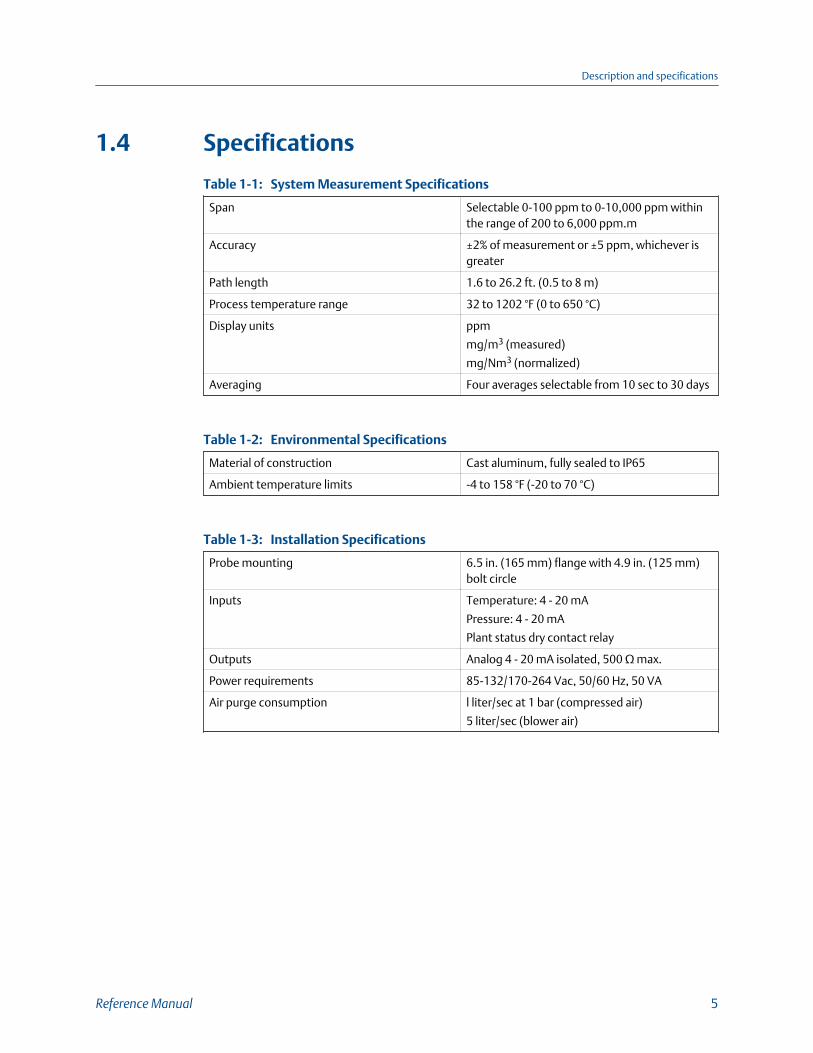
1.4 Specifications
System Measurement SpecificationsTable 1-1:
Span Selectable 0-100 ppm to 0-10,000 ppm withinthe range of 200 to 6,000 ppm.m
Accuracy ±2% of measurement or ±5 ppm, whichever isgreater
Path length 1.6 to 26.2 ft. (0.5 to 8 m)
Process temperature range 32 to 1202 °F (0 to 650 °C)
Display units ppm
mg/m3 (measured)
mg/Nm3 (normalized)
Averaging Four averages selectable from 10 sec to 30 days
Environmental SpecificationsTable 1-2:
Material of construction Cast aluminum, fully sealed to IP65
Ambient temperature limits -4 to 158 °F (-20 to 70 °C)
Installation SpecificationsTable 1-3:
Probe mounting 6.5 in. (165 mm) flange with 4.9 in. (125 mm)bolt circle
Inputs Temperature: 4 - 20 mA
Pressure: 4 - 20 mA
Plant status dry contact relay
Outputs Analog 4 - 20 mA isolated, 500 Ω max.
Power requirements 85-132/170-264 Vac, 50/60 Hz, 50 VA
Air purge consumption l liter/sec at 1 bar (compressed air)
5 liter/sec (blower air)
Description and specifications
Reference Manual 5

1.5 Rosemount™ CCO 5500 ordering information
Model Description
CCO 5500 Carbon Monoxide Analyzer - across-the-stack
Level 1 power requirements
01 110/220 Vac, 50/60 Hz
Level 2 control module display/keypad
01 English
Level 3 calibration options
00 None
01 Calibration check cell and holder
Description and specifications
6 Rosemount CCO 5500

2 Install
WARNING!
Before installing this equipment, read Essential Instructions. Failure to follow safety instructionscould result in serious injury or death.
WARNING!
ELECTRICAL HAZARDInstall all protective equipment covers and safety ground leads after installation. Failure toinstall covers and ground leads could result in serious injury or death.
WARNING!
ELECTRIC SHOCKBefore making any electrical connections, make sure the AC power supply is first switched off.Failure to do so could cause personal injury or even death. Make sure that the voltage andfrequency of the AC supply match the designations on the analyzer component tags.
2.1 Unpack the equipmentA typical Rosemount™ CCO 5500 Carbon Monoxide (CO) Analyzer should contain thefollowing items.
Refer to Figure 1-1 for an illustration of each of these components. Record the partnumber, serial number, and order number for each major component of your system.
1. Source with 33 ft. (10 m) of cable and air purge
2. Receiver with 33 ft. (10 m) of cable and air purge
3. Interconnect cable 3 ft. (0.91 m)
4. Control unit
5. Power supply
6. Gaskets (four)
7. Selected screws and washers
2.2 Safety considerationsPower is supplied to the whole system via the power supply unit. During installation, donot connect the system to the facility power source until all units are in place and fullywired. If used, keep the isolating valves closed. You must turn off the compressed air
Install
Reference Manual 7

supplied to the purges until the full installation is complete. If you do any servicing orrewiring, ensure that the power supply is isolated. During configuration, the systemrequires electrical power, compressed air, and open isolating valves.
2.3 Cable requirements1. Power supply to signal processor - seven-core, overall screen, multi-stranded, 6/0.2
mm. 0.5 mm2.
NOTICEAlthough shielded cable is specified for the interconnecting cable, it is not necessary toground the cable.
2. Current loop output - any suitable two-conductor cable, maximum length dependson keeping output load within the 500 ohm maximum load requirement.
3. Contact outputs - any two-conductor cable capable of supplying the power to thewarning device/relay, etc. 250 V, 10 A maximum.
4. A.C. power - any suitable three-conductor power cable capable of transmitting 50VA.
5. Serial data link (if required) - twin twisted pair shielded cable.
6. Analog inputs - any suitable two-conductor cable; Rosemount™ instruments have aninternal impedance of 240 ohms for these inputs.
2.4 Selecting locationRosemount™ designed the equipment for mounting on boiler ducting or stacks open tothe weather. The instrument is fully sealed and requires no further enclosures orprotection. The specific location of the instrument depends on the application and userrequirements. Consider the following when choosing a site.
Refer to Figure 1-2 for a typical system arrangement.
1. The site must be accessible at both sides of the duct for servicing the source andreceiver.
2. The site should be as free from extremes of temperature and vibration as possible.Permissible ambient temperature range is -4 °F to 158 °F (-20 °C to 70 °C).
3. Flue gas temperatures should not exceed 572 °F (300 °C) at the point ofmeasurment.
NOTICEThe instrument can achieve temperatures up to 1200 °F (600 °C), but degradation ininstrument accuracy will occur.
4. There must be an uninterrupted sight path available between the source andreceiver.
Install
8 Rosemount CCO 5500

5. The maximum cable length allowed between the power supply and the source is 33ft. (10 m).
6. The maximum cable length between the power supply and the receiver is 82 ft. (25m).
2.4.1 Points to considerPath length
1. Too long [> 26 ft (8 m)]: low energy available.
2. Too short [< 1.6 ft (0.5 m): optical problems
Flue gas temperature
1. Too low (< dewpoint): potential water droplets.
2. Too high [> 572 °F (> 300 °C)]: reduced sensitivity.
Ambient temperature
1. Too low [< -4 °F (< -20 °C)]: condensation on lenses.
2. Too high [> 158 °F (> 70 °C)]: potential instrument problems.
Measurement range
1. Minimum range depends on acceptable measurement uncertainty which is 10 ppm-meters. For example, for the level of uncertainty to be below 2% of range, theminimum range would be 500 ppm-meters.
NOTICE10 ppm CO = 12.5 mg/m3
2. For increased sensitivity (reduced uncertainty of measurement), the path lengthmust be maximized.
3. Maximum range is 6,000 ppm-meters.
NOTICE
To correct ppm-meters to effective ppm, divide the path length (in meters).
2.5 Mechanical installationThe transmitter and receiver units are mounted on a site mounting flange on oppositesides of the duct. To protect operators, Rosemount™ recommends using an isolating valvefor ducts that operate at a higher than atmospheric pressure.
Use a stand-off pipe [nominal bore 3 in. (75 mm) - not supplied] between the duct and thesite mounting flange. The pipe should be long enough to clear the equipment from anyduct lagging; it also helps to insulate the equipment from any high duct temperatures.
Install
Reference Manual 9
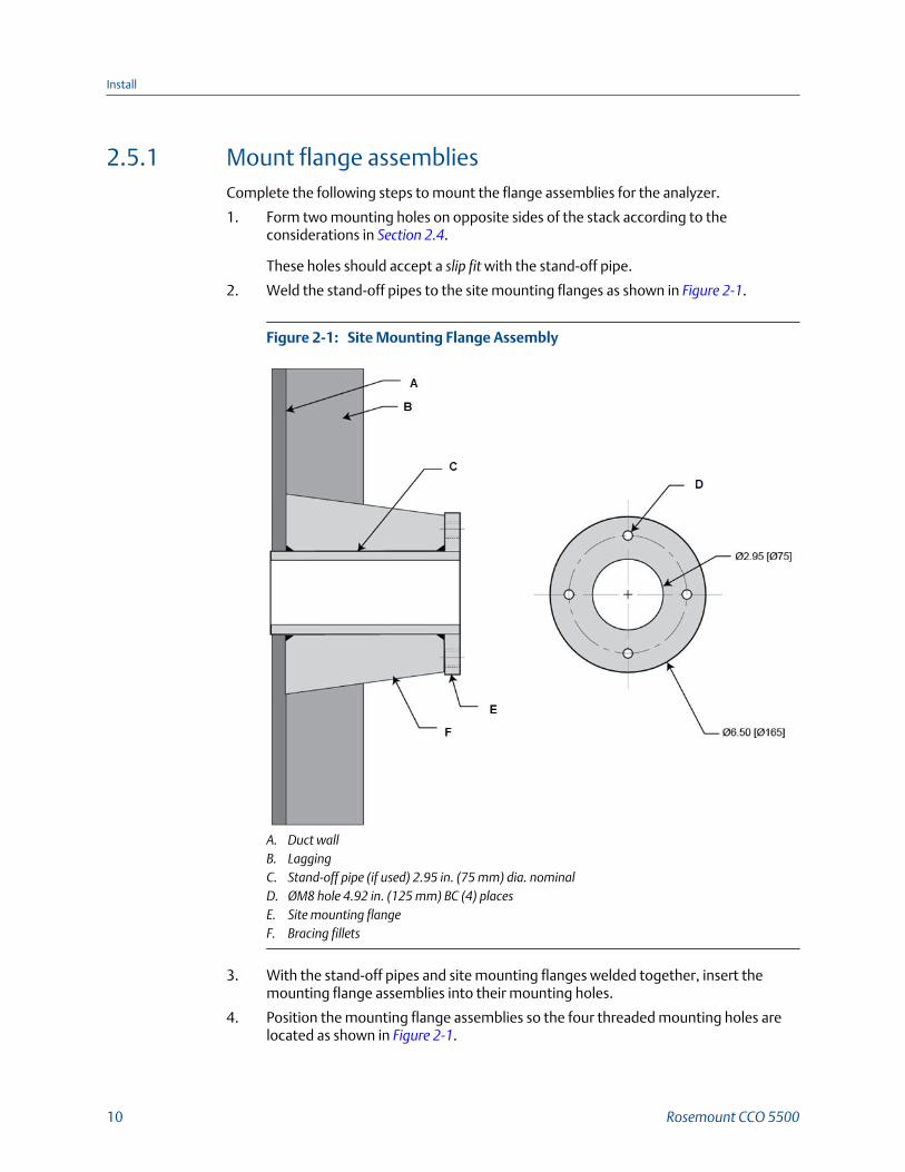
2.5.1 Mount flange assembliesComplete the following steps to mount the flange assemblies for the analyzer.
1. Form two mounting holes on opposite sides of the stack according to theconsiderations in Section 2.4.
These holes should accept a slip fit with the stand-off pipe.
2. Weld the stand-off pipes to the site mounting flanges as shown in Figure 2-1.
Site Mounting Flange AssemblyFigure 2-1:
A. Duct wallB. LaggingC. Stand-off pipe (if used) 2.95 in. (75 mm) dia. nominalD. ØM8 hole 4.92 in. (125 mm) BC (4) placesE. Site mounting flangeF. Bracing fillets
3. With the stand-off pipes and site mounting flanges welded together, insert themounting flange assemblies into their mounting holes.
4. Position the mounting flange assemblies so the four threaded mounting holes arelocated as shown in Figure 2-1.
Install
10 Rosemount CCO 5500

NOTICERosemount™ suggests that you tack weld the stand-off pipe to the duct and check thealignment visually before making a complete weld.
5. Look through one of the mounting flange assemblies.
If the you can see the orifice across the stack clearly, the alignment is satisfactory.The alignment of these holes is not critical; an integral adjustable mount cancompensate for up to 4 degrees of misalignment.
6. Weld the assemblies in place.
To avoid vibration and movement, you may need to fit spreader plates or bracingfillets on the mounting flange assembly as shown in Figure 2-1.
2.5.2 Isolating valvesTo protect operators, Rosemount™ recommends that you use customer supplied isolatingvalves (Figure 2-2) for ducts that operate at higher than atmospheric pressure. Valveselection and installation is your responsibility.
Isolating Valve and Air Purge ArrangmentFigure 2-2:
A. Isolating valve (customer supplied)B. Adjusting nutsC. Locking nutsD. Air purge portE. Pressure regulator assemblyF. Rear flangeG. Front flangeH. Site mounting flange
Install
Reference Manual 11

After the isolating valves are installed in the site mounting flanges, connect the purge airsupply and install air purge units according to the following instructions.
2.5.3 Purge air supplyThe purpose of the purge air is to keep the windows of the source and the receiver clean.Always connect the purge air supply to the air purge units before you install the air purgeunits on the process duct. Purge air may be supplied by one of the following threemethods.
Negative pressure duct
If the duct operates at a negative pressure under all firing conditions, you may simply leavethe air purge inlets open and allow the negative draft in the duct to draw in ambient air.
You must supply the air purge units for positive pressure ducts with compressed air orblower air to prevent contamination of the source and receiver units.
Compressed air
You may use compressed air to provide the air flow required. An air supply of 14.7 psi (1bar) is required, and the consumption is 2.2 cfm (1 liter/second) per purge. Use a finecontrol flow regulator and filter.
Blower air
You may use a blower to provide the air to the air purge. Customers may specify their ownblower. The blower should deliver 11 cfm (5 liters/second) per purge against the workingpressure of the duct.
Install
12 Rosemount CCO 5500

Air Purge MountingFigure 2-3:
A. Site mounting flange or isolating valve flangeB. Adusting nutsC. Locking nutsD. Air purgeE. Rear flangeF. Front flange
2.5.4 Air purge unitsUse the general procedure that follows to install the air purge units on the site mountingflanges or on the exposed flanges of the customer supplied isolating valves, if used.
CAUTION!
CONTAMINATION
Always connect and turn on the purge air supply to both air purge units before mounting theair purge units. Failure to flow purge air may allow the optical surfaces of the source andreceiver units to become severely contaminated.
Procedure
1. Remove the four locking nuts holding the front flange to the rear flange (Figure 2-3).
2. Carefully work and pull the front flange from the air purge unit.
3. Align the four holes on the front flange with the four holes on the site mountingflange.
4. Fasten the front flange to the site mounting flange with the four countersunk screwsand gaskets provided.
5. Connect and turn on a compressed air or blower air supply to the purge unit. Alwaysflow purge air before installing an air purge unit on the duct.
Install
Reference Manual 13

6. Install the air purge unit on the front flange as shown.
7. Install and tighten the four locking nuts removed in Step 1.
2.5.5 Source and receiver unitsUse the following procedure to install the source and receiver units on the air purge units.
1. Insert a flexible gasket between the air purge unit and the source or receiver unit.
2. Dowel pins (Figure 2-4) ensure that the source and receiver units and the air purgeunits mount in a fixed rotary position. Align the dowel pin and dowel pin hole.
Air Purge and Source Unit Mounting FeaturesFigure 2-4:
A. Locking nutB. Window plateC. SourceD. Alignment dowel pin holeE. Threaded screw holeF. Rear face of air purge
3. Attach the source or receiver to the rear face of the air purge and install the fourscrews provided (Figure 2-5).
Install
14 Rosemount CCO 5500

Air Purge and Source Units (Installed)Figure 2-5:
A. Site mounting flangeB. Front flangeC. GasketD. Source or receiverE. Window plateF. Air purgeG. Rear flange
2.5.6 Control unitRosemount™ supplies adequate cableto locate the control unit up to 33 ft. (10 m) from thereceiver. Do not exceed the 33 ft. (10 m) cable length.
1. Loosen the four captive cover screws and remove the cover.
2. Unplug the ribbon cable connector on the cover side.
3. Fasten the control unit to a firm vertical support. Install four mounting screws in themounting holes provided.
Refer to Figure 2-6 for mounting dimensions.
Install
Reference Manual 15

Mounting Dimensions for the Control and Power Supply UnitsFigure 2-6:
A. Cover seal - Note that the mounting holes are outside the extent of the seal.B. CoverC. BaseD. 4 Holes for M6 mounting screwsE. Cable gland entry blanking pageF. Approx. 6 in. (150 mm) free space required below box for cablesG. Assembled box 4.3 in. (110 mm) deep
NOTICEThe unit mounting holes are located outside the seal. You do not need to seal themounting holes after installation or to remove the circuit boards from the unit prior tomounting.
2.5.7 Power supply unitRosemount supplies adequate cableto locate the power supply unit up to 33 ft. (10 m)from the source unit. You may use a maximum cable length of 82 ft. (25 m) to connect thepower supply unit to the receiver. Do not exceed the 82 ft. (25 m) maximum cable length.
Dimensions and mounting hole locations are identical to the control unit and are shown in Figure 2-6.
Install
16 Rosemount CCO 5500
2.6 Electrical data
2.6.1 AC suppliesYou can power the Rosemount™ CCO 5500 Analyzer from either 85-135 Vac or 170-264Vac at 50/60 Hz. A switch within the power supply unit selects the input voltage, and aninternal 2 A fuse protects the instrument. The analyzer tolerates voltage fluctuationswithin these ranges without losing performance. The total power requirement for theanalyzer is less than 50 VA.
2.6.2 OutputsThree analyzer outputs are available:
1. Selectable, fully isolated 4-20 mA or 0-20 mA % CO concentration, 500 ohmsmaximum load.
2. Single pole, switching relays (rated 250 V, 10 A) for the following outputs:
• Alarm trigger at a selectable gas threshold.
• Data-valid indication active during power failure and any equipment faultcondition. See Chapter 6 for further details.
3. Four-wire serial data link for two-way communication between the control unit anda distributed control system or other process control system.
2.6.3 Normalizing inputsThe analyzer can hold pressure, temperature, and oxygen values to normalize thecalculated gas value to standard conditions. The instrument may read these values usingthe following methods:
1. Fixed value from the keypad.
2. 4-20 mA outputs from measurment transducers. You can set the rangesrepresented by these inputs from within the processor. These are analog processinputs to the control unit.
3. When the analyzer is part of an integrated system, the serial data line can carry thenormalizing values.
2.6.4 Plant status inputThe plant status input parameter is available to prevent the rolling average data frombeing diluted by measurements made while the plant is shut down. The parameter isgoverned by one of three choices:
1. Serial input (from an integrated system)
2. Logic input (terminals PS1 and PS2 in the control unit)
3. Multiple (five variables)
a. Temperature
Install
Reference Manual 17

b. Oxygen
c. Pressure
d. Water vapor
e. Logic input
You can set these parameters in Mode 5. Chapter 4 describes each of these parameters.
During normal operation, the plant status registers as ON. However, if the plant statusinput is lost, the status changes to OFF, and the averaging data (seconds, minutes, hours,days) is not updated.
NOTICE
During normal operation, do not link terminals PS1 and PS2 together.
2.7 Electrical connectionsAll equipment wiring must conform to local and national codes. Read and observe thefollowing instructions before making electrical connections.
WARNING!
ELECTRIC SHOCKDisconnect and lock out power before connecting the power supply to the analyzer.
WARNING!
ELECTRIC SHOCKInstall all protective covers and safety ground leads after installation. Failure to install coversand ground leads could result in serious injury or death.
WARNING!
ELECTRIC SHOCKTo meet the safety requirements of IEC 1010 (EC requirement) and ensure safe operation of thisequipment, connect to the main electrical power supply through a circuit breaker (min. 10 A)which will disconnect all current-carrying conductors during a fault situation.This circuitbreaker should also included a mechanically operated isolating switch. If not, then locateanother external means of disconnecting the supply from the equipment close by. Circuitbreakers or switches must comply with a recognized standard, such as IEC 947.
NOTICE
To maintain proper earth grounding, ensure a positive connection exists between thetransmitter housing and earth. The connecting ground wire must be 14 AWG minimum.
Install
18 Rosemount CCO 5500

NOTICE
Line voltage, signal, and relay wiring must be rated for at least 221 °F (105 °C). Make sure thatthe voltage and frequency of the AC power supply match the required power specifications.
NOTICE
If metal conduit is used with the power supply unit and/or the source unit, bond the conduitreliably to protective earth. Grounding points inside the units are not bonded to PE and do notprovide adequate grounding.
2.7.1 Installation of cablesDecide routing for all non-power cables (both those supplied by Rosemount™ and thosesourced locally). Use common routing wherever possible and install leaving sufficient free-end length to make final connections.
Install power cables separately using different routes if possible to reduce the risk of cross-interference. Leave sufficient free-end length to make final connections.
Rosemount supplied cables are provided with ferrite beads fitted to all cores to protectagainst interference. Do not modify the cables without consulting Rosemount.
2.7.2 Cable connectionsUse the following procedure to make cable connections between the source, receiver,power supply unit, and control unit.Figure 2-7 displays a system wiring diagram. Figure 2-8 displays the location of powersupply and control unit connectors, etc.
Install
Reference Manual 19

System Wiring DiagramFigure 2-7:
Install
20 Rosemount CCO 5500

Wiring Connector Locations (Power Supply Board)Figure 2-8:
A. 110/220 Vac power inB. Data-valid relay contactsC. Alarm relay contactsD. Interconnect cable contacts
Install
Reference Manual 21

Wiring Connector Locations (Control Board)Figure 2-9:
A. Plant status inB. Analog outC. Receiver cable inD. Serial data input
Procedure
1. Install the receiver cable in the center rear cable port of the control unit enclosure.Provide adequate free wire length for making connections to the control boardterminals 16 through 22. Tighten the cable gland nut.
2. Connect the receiver cable wires to the control board terminals 16 through 22according to the wiring diagram, Figure 2-7.
Do not connect the receiver cable shield wire at the control unit.
Install
22 Rosemount CCO 5500

3. Install the source cable in the right front cable port of the control unit enclosure.Provide adequate free wire length for making connections to the control boardterminals 8 through 12. Tighten the cable gland nut.
4. Connect the source cable wires to the control board terminals 8 through 12according to the wiring diagram, Figure 2-7.
Do not connect the source cable shield wire at the control unit.
5. Install one end of the power supply to control unit interconnect cable in the centerfront cable port of the control unit enclosure. Provide adequate free wire length formaking connections to the control board terminals 1 through 7. Tighten the cablegland nut.
6. Connect the cable wires to the control board terminals 1 through 7 according to thewiring diagram, Figure 2-7.
Do not connect the cable shield wire at the control unit.
7. Install the opposite end of the power supply to control unit interconnect cable inone of the right hand cable ports of the power supply unit enclosure. Provideadequate free wire length for making connections to the power supply boardterminals 1 through 7. Tighten the cable gland nut.
8. Connect the cable wires to the power supply board terminals 1 through 7 accordingto the wiring diagram, Figure 2-7.
Do not connect the cable shield wire at the power supply unit.
9. Install the 110/220 Vac power cable in one of the left hand cable ports of the powersupply unit enclosure. Provide adequate free wire length for making connections tothe power supply board terminals: L, N, and E. Tighten the cable gland nut.
10. Connect the cable wires to the power supply board terminals L, N, and E accordingto the wiring diagram, Figure 2-7.
Do not connect the power cable to the facility power source at this time.
11. Verify that the power switch is in the correct position.
The voltage position selected must match the voltage supplied to the Rosemount™
CCO 5500 Analyzer at your facility.
12. Connect two separate earth ground leads to the ground screws located on the lefthand side of the power supply unit and control unit enclosures.
NOTICETo maintain proper earth grounding, ensure a positive connection exists between theenclosures and the earth. The connecting ground wires must be 14 AWG minimum.
Install
Reference Manual 23

Install
24 Rosemount CCO 5500
3 Configuration and startup
3.1 IntroductionYou may need two hours or more to configure the instrument, and you need to completethe following tasks:
• Power up
• Alignment*
• Gain adjustment*
• Set operating parameters
• Calibration*
Note*Perform these operations when a clean stack condition exists.
3.2 Safety considerationsThe power supply unit supplies power to the analyzer system. Before removing anyequipment covers, lock out and tag out power to the supply unit.
WARNING!
ELECTRIC SHOCKDisconnect and lock out power before connecting power to the analyzer.
3.3 Power up the Rosemount™ CCO 5500 AnalyzerUse the following procedure to power up the analyzer.
1. Make sure that the voltage and frequency of the AC power supply match therequired power specifications.
2. With the AC power supply locked out and tagged off, unscrew and remove thepower supply unit cover.
3. Select the correct power supply voltage using the AC power selector switch shownin Figure 3-1.
Configuration and startup
Reference Manual 25

Power SupplyFigure 3-1:
A. AC power selector switchB. Rail indication LED
4. Power up the Rosemount CCO 5500 Analyzer and verify that the power supply railindication LED (Figure 3-1) lights up.
5. Install and fasten the power supply unit cover.
6. Check that the LCD display is functioning at the control unit.
While the source unit is warming up, the LCD display shows WAITING FOR REFERENCE.When the source unit reaches an adequate temperature for the reference to be detected,the LCD display shows the message STABILIZING REF, along with the frequency andmark/space ratio. See Section 4.9 for further details.
The reference frequency takes some time to stabilize (about five minutes from coldstartup). When the reference frequency is within tolerance for 10 consecutivemeasurement cycles, the instrument automatically changes to the OPERATING mode. Thisis Mode 1 and is indicated by a number 1 appearing in the top left corner of the LCDdisplay. The display shows a reading in ppm; this is not an accurate reading until allconfiguration and startup procedures are completed.
Before conducting the alignment procedure, allow 30 minutes for the source temperatureto become stable.
3.4 AlignmentFor the instrument to operate properly, the source and receiver units must be aligned.Rosemount™ has built in a degree of optical redundancy; normal duct movements do notaffect the operation of the instrument. Read and understand this entire procedure beforestarting the alignment.
Configuration and startup
26 Rosemount CCO 5500

1. See Figure 2-5. Unscrew the four screws that secure the receiver to the air purge.Remove and place the receiver in a safe location.
2. Go to the source unit location. To align the source, turn the adjusting nuts(Figure 3-2). Use opposing adjusting nuts to align the source unit in one plane, thenthe other.
NoteYou can achieve receiver alignment by monitoring the output of the detector directly. Use avoltmeter set to AC volts (10 V max.) to measure across test points S0V and S2 for D3, andS0V and S1 for D1 on the receiver control board (Figure 3-3). This alignment method is usefulwhen the receiver is not located near the control unit.
Alignment FeaturesFigure 3-2:
A. Adjusting nutsB. Locking nutsC. Air purgeD. Rear flangeE. Front flange
Configuration and startup
Reference Manual 27

Receiver Test PointsFigure 3-3:
A. S1 whiteB. S2 blueC. S0V greenD. Voltage indication LEDs
3. Adjust the alignment until the bright red disc of the source is located centrally in thefield of view when viewed from the receiver air purge. When the source unit isaligned, tighten the locking nuts.
4. Install and tighten the receiver on its air purge using the four screws removed in Step 1.
5. At the control unit keypad, press MODE four times to select SET UP mode (Mode 5).When 5 (SET UP) is displayed on the LCD, press ENTER to access the SET UPmode.
NoteThe analyzer uses a security code to prevent unauthorized alteration of settings. The defaultcode set at the factory is 0000.
The keypad cursor flashes over the first digit of the security code.
Configuration and startup
28 Rosemount CCO 5500

6. Use the arrow keys to enter the desired value for this digit. Press ENTER to select thedisplayed value; the cursor moves to the second digit. Select the value for thesecond digit and press ENTER. Continue this process for each digit of the securitycode.
When the fourth digit is correctly entered, the processor enters Mode 5.
7. When in Mode 5, select Calibrate using the keypad arrow keys; press ENTER to accessthe Calibrate menu.
8. Use the arrow keys to select SET DETECTORS; press ENTER.
The display shows the D1 and D2 detector levels.
CAUTION!If the analyzer is not in SET UP mode, the gas cell at the source unit periodicallyinterrupts the IR beam and make alignment difficult.
9. Adjust the receiver alignment, using the adjusting nuts, Figure 3-2. Adjust in oneplane, then in the other.
As a rule, the D2 detector level is affected to a greater extent by adjustment in oneparticular plane. The D1 detector level is affected more by adjustment in the otherplane.
10. Make sure the maximum possible values of both D1 and D2 are reached. After youachieve alignment, tighten the locking nuts.
NoteThe alignment of the receiver unit is important. Make sure to obtain the maximum values ofD1 and D2.
11. If the displayed detector level is below 5000, increase the gain at the control unit tobetween 12000 and 14000.. If the detector level is above 15000, reduce the gain tobetween 12000 and 14000.
Refer to Section 3.5 for details.
12. To fine tune the alignment, repeat adjustments of Step 9 at the source unit. Again,make sure the values of D1 and D2 are appropriate. Lock the source unit in placewhen the maximum values are achieved.
13. When you have properly completed the alignment, there is rarely any need forfurther alignment adjustments.
3.5 Detector levelsThe gain of the detector signals is set in two locations:
1. In the receiver, two potentiometers set the gain. Refer to Section 3.5.1.
Configuration and startup
Reference Manual 29

2. In the control unit trim, potentiometers adjust the level of the D1 and D2 signalsbefore they enter the microprocessor. Refer to Section 3.5.1.
It is essential that you properly conduct the alignment procedure and obtain a maximumdetector signal before attempting to optimize the detector levels.
3.5.1 Receiver gain adjustmentTo give an optimum signal-to-noise ratio, the detector levels must be maximized. For thebest signal-to-noise ratio, you must set the gain of the detector signals in the receiver to amaximum without saturating. Rosemount™ sets the gains at a path length of 6.5 f.t (2 m).If the path length is above 13 ft (4 m) or below 5 ft (1.5 m), you may need to adjust tooptimize the detector levels.
1. Enter Mode 5 → Calibrate → Set Detectors and display the value of D2/D1.
2. Loosen the receiver cable gland so the receiver cable can slip when you remove thewindow plate.
3. Pull the window plate (Figure 3-4) from the receiver to access the detectors.
Receiver Trim PotsFigure 3-4:
A. Trim pot for end detector D1B. Trim pot for side detector D2
4. Trim potentiometer(s) set the gain.
An AC voltmeter measures the gain levels.
5. Connect the voltmeter to the test points on the control unit (18/20 for D1 and19/20 for D2). Increase the gain using the trim pot at the end detector D2 until thevoltage is between 1 - 4 Vac.
Configuration and startup
30 Rosemount CCO 5500

6. Repeat Step 5 for the side detector D1 measuring across the test points.
7. When the detector levels are satisfactory, replace the cover.
NoteIf the duct is operating and a high opacity may be in the path, reduce the set voltages to 2 Vrms maximum. This should prevent saturation should the opacity level drop off.
3.5.2 Control unit gain adjustmentAfter you have optimized the detector level(s) at the receiver, optimize the levels withinthe microprocessor. Make the adjustment with two trim potentiometers in the controlunit.
1. Set the gain to a minimum by turning the D2 detector trim pot (Figure 3-5) fullyclockwise.
D2 is a 20-turn potentiometer.
Configuration and startup
Reference Manual 31

Gain Adjust PotentiometersFigure 3-5:
A. Trim potB. Test pointC. LEDD. D2 trim potE. D1 trim potF. PlantG. AnalogH. ReceiverI. Serial data
2. Enter Mode 5 → Set Detectors and display the values of D2 and D1. Turn the trim potcounterclockwise until the D2 level is between 12,000 and 15,000. Allow timebetween adjustments for the readings to settle.
NoteIf the duct is operating and the opacity levels are high, reduce the D2 level to about 8,500.This should prevent saturation should the opacity level drop off.
Configuration and startup
32 Rosemount CCO 5500

3. To ensure that the detector signal is not saturating, observe the saturation countsignal displayed next to the detector levels. If a SAT # of more than 0 is displayed,turn the trim pot slightly to reduce the gain. Reduce the gain until a SAT # of 0 isdisplayed.
4. If saturation is indicated with the trim pot turned fully clockwise, reduce the gain inthe receiver and repeat the procedure.
5. Repeat Step 1 through Step 3 for the D1 level using the D1 trim pot.
NoteRosemount™ has designed the circuits so that wherever saturation occurs (receiver or controlunit), the microprocessor always detects it. If the displayed detector levels cannot be set towithin this band or saturation cannot be avoided, optimize the detector levels ar the receiver.Refer to Section 3.5.1.
3.6 Source adjustmentsTwo trim potentiometers within the source unit allow adjustments to be made to theintensity of the source and to the frequency of the chopper motor. Rosemount™ sets theseat the factory, and they rarely need adjustment. Rosemount recommends that you consultthe company before making any adjustments within the source unit.
CAUTION!
DECREASED SOURCE LIFE
Increasing source intensity may severely reduce the source life.
3.6.1 Source intensityComplete the following steps to adjust the source intensity in the analyzer.
1. Loosen and slide the source unit cable gland so the cable can slip when the rearcover plate is removed.
2. Unscrew and remove the rear cover plate.
3. A trim pot (Figure 3-6) allows adjustment to the intensity of the source. Turn the trimpot clockwise to increase the source intensity.
Configuration and startup
Reference Manual 33

Source Intensity Trim PotFigure 3-6:
A. Trim pot
3.6.2 Chopper frequencyComplete the following steps to adjust the analyzer's chopper frequency.
1. Unscrew and remove the source from the air purge.
2. Unscrew and pull the window plate from the front of the source unit.
See Figure 3-7. A trim pot (VR1) allows you to adjust the frequency of the choppermotor.
Configuration and startup
34 Rosemount CCO 5500

Chopper Frequency Trim PotFigure 3-7:
A. Trim pot VR1
3. To increase the chopper frequency, turn the trim pot counterclockwise.
3.7 Set up modeTo prevent any unauthorized changes, you must enter a four digit security code to enterthe set up mode.You must set operating parameters in the instrument for proper analyzer operation. Alloperating parametrs are set within the control unit using the SET UP mode. In the SET UPmode, parameters are held in non-volatile memory and retained in the event of a powerloss.
Even if the measured data is not going to be normalized, you must set the normalizingparameters to ensure proper analyzer operation.
NoteWhen you select SET UP mode, the instrument suspends motor operations, and the Data Valid LEDgoes dim. If no key is pressed within five seconds after selecting SET UP mode, the instrument controlreverts to OPERATING mode.
Chapter 4 lists all parameters in full. Basic details are given here for configuration purposes.
To aid configuration and to record any subsequent changes to the operating parameters,Rosemount recommends completing to provide a record of the instrument setup.
Configuration and startup
Reference Manual 35

Procedure
1. Press MODE unil the number 5 is displayed in the top left corner.
After you correctly enter the security code, there are six submodes of operationfrom which the set up parameters may be changed. These six submodes are:
a. Set Averages: The four averaging stack times (seconds, minutes, hours, anddays) may be set as required.
b. Configure O/P - Analog output setup: Origin, units, span, rolling average, andfault condition.
c. Parameters: The following are set from this mode: security code, identitynumber, path length, alarm level, cal factor, and plant status.
d. Normalization: You may set up all normalization parameters from this mode.
e. Reset Average: Select this submode to reset the four averaging stacks.
f. Calibrate: Set the outputs of the detectors and the basic calibration for theinstrument.
2. Use the arrow keys to toggle between these six options and press ENTER when thedesired option is displayed.
3.7.1 Enter security codeComplete the following steps to enter the security code.
1. Once the display is as shown here, press ENTER to gain access to SET UP mode.
The cursor flashes over the first digit of the security code number.
2. Select the required first digit with the arrow keys and press ENTER.
3. Repeat this procedure for the remaining three numbers.
If the code is correct after you press ENTER on the last digit, the sequence iscontinued. If it is not correct, the instrument returns to OPERATING mode. Refer to Section 3.7.4 for further details.
NoteRosemount™ sets the code number to 0000 at the factory; you should change it in SET UPmode.
3.7.2 Set averagesThe instrument calculates four separate averages. These are defined in units of seconds,minutes, hours, and days. You can use any of the four averaging stacks to provide theinstrument's analog output. You can set each averaging time within predefined limits.
Configuration and startup
36 Rosemount CCO 5500
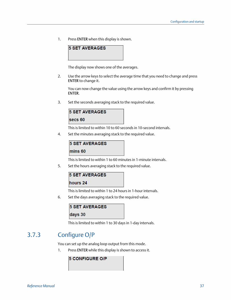
1. Press ENTER when this display is shown.
The display now shows one of the averages.
2. Use the arrow keys to select the average time that you need to change and pressENTER to change it.
You can now change the value using the arrow keys and confirm it by pressingENTER.
3. Set the seconds averaging stack to the required value.
This is limited to within 10 to 60 seconds in 10-second intervals.
4. Set the minutes averaging stack to the required value.
This is limited to within 1 to 60 minutes in 1-minute intervals.
5. Set the hours averaging stack to the required value.
This is limited to within 1 to 24 hours in 1-hour intervals.
6. Set the days averaging stack to the required value.
This is limited to within 1 to 30 days in 1-day intervals.
3.7.3 Configure O/PYou can set up the analog loop output from this mode.
1. Press ENTER while this display is shown to access it.
Configuration and startup
Reference Manual 37

2. Press the arrow keys to step through the available options.
3. Press ENTER to access and change the displayed parameters of each of the sixavailable options listed below:
a. Output
b. Averages
c. Units
d. Output Span
e. Fault Condition
f. Set mA Output
Output
You can set an origin of 0 or 4 mA for the current loop output. The arrow keys togglebetween these two options. Press ENTER to enter the new value.
Average
You may use any of the four averaging stacks (seconds, minutes, hours, and days) for theanalog output. You can select them with the arrow keys and enter them with the ENTERkey.
Units
The analog output can represent the gas concentration in units of mg/m3, mg/Nm3, orvpm. The arrow keys toggle between these three options. Press ENTER to enter the newvalue.
Output Span
Select the required span using the arrow keys for each digit. Press ENTER to enter the valueof each digit. The units are displayed in vpm, mg/m3, or mg/Nm3, depending on what hasbeen selected beforehand.
Configuration and startup
38 Rosemount CCO 5500

NoteOnce you select Output Span, the current value is displayed for one second. The first digit of thedisplay then defaults to zero; thus you must re-enter the span value for the unit to function correctly.
Fault conditionIf a fault condition occurs, you may set the current output of the instrument to one of thefollowing options:
Procedure
1. Set the output at 0 mA - ZERO.
2. Adjust the output to the calculated gas concentration even though a fault conditionexists - MEAS.
3. Hold the last selected gas concentration - HOLD.
4. Set the output to full scale (20 mA) - F.S.
Press the arrow keys to select one of these options; when the desired output is displayed,press ENTER to confirm.
Set mA output
NoteThis is set at the factory and should not be altered without due consideration.
From this option, the current levels of the analog output are set up. Press ENTER to selectit, and the instrument prompts you to set the current levels at 0 and 20 mA.
When this is displayed, set the current output to 0 mA as measured with a calibratedcurrent meter across the analog ouput loop terminals; do not connect anything else tothese terminals when setting up the output.
Use the two arrow keys to adjust the value; the UP arrow takes the current output up, andthe DOWN arrow takes it down. Press ENTER when the correct output is displayed on theammeter.
Configuration and startup
Reference Manual 39

NoteZero mA should be set up no matter what has been selected as the base of the current output. This isfactory set.
In a similar manner to the above, set the current output level to 20 mA.
3.7.4 ParametersComplete the following steps to set the parameters.
1. With this option displayed, press ENTER to access the list of six available options.
The arrow keys cycle through these options.
2. When the option you need to change is displayed, press ENTER.
3. When you have made all required changes, select EXIT and press ENTER.
The six available options are:
a. Security Number
b. Identity Number
c. Path Length
d. Alarm
e. Cal. Factor
f. Plant Status Input
Security NumberTo prevent any unauthorized tampering with the setup information, it is important tochange the security code from the factory setting.
Select each digit with ENTER and change it with the arrow keys.
NoteIt is important to make note of this number; otherwise, it will not be possible to change theinstrument set up.
Configuration and startup
40 Rosemount CCO 5500

Identity Number
If you are using the system as part of an integral monitoring system and are using the serialinput and outputs, the central processor requires a Device Identity to identify eachinstrument. This number must be unique for each equipment item and can be set from 1to 30 as required.
Path Length
NoteOnce you select path length, the instrument displays the current value for one second. The first valueof the display then defaults to zero; therefore, you must re-enter the value to calculate the gasconcentrations correctly.
The transmissivity of any gas depends both on the concentration and on the path lengththrough which the radiation is transmitted. Similarly, the output of the Rosemount™ CCO5500 Analyzer gas monitor also depends on the path length of the flue gas through whichthe radiation is transmitted.
Refer to Section 2.4.1.
The Rosemount CCO 5500 Analyzer is sensitive to the product of concentration and pathlength. In order to obtain a true value of concentration of gas, you must input the correctpath length into the processor. The processor then uses the value to produce a final valueof gas concentration.
NoteThe path length entered must represent the length of the actual gas pass, not the flange to flangedimension between the source and receiver.
Alarm
A contact output is available to warn of a high gas concentration. You may trigger thecontact output from any of the four averaging stacks. Select the source with the arrow keyand enter it with ENTER.
Configuration and startup
Reference Manual 41

Select the units for the alarm; these may be different than the units selected for the analogoutput.
After you select the source, the instrument requires a level that will trigger the output. Setthe desired level with the arrow keys.
Cal Factor
NoteFirst, record the original Cal Factor before entering this mode as displayed in Mode 4 → CalibrationData. The Cal Factor is lost when the menu option is entered.
During the calibration routine, the instrument calculates a Cal Factor which sets the basiccalibration of the instrument. You may change this value from this mode.
NoteSince this value controls the calibration of the instrument, only change if necessary.
Plant Status InputUse this to determine whether the plant is operating under correct conditions.
There is a choice of three controls for plant status: Logic Input, Serial Input, and Multiple. Youcan only use one to control plant status at any one time.
• Logic Input
If the PS1 and PS2 terminals are linked in the control unit, the logic contact is made,and the plant status is OFF. You may link these terminals manually during a plantshut down, or you may wire them to a switch/contact outside the unit (e.g., a valuethat opens and closes the duct). Press ENTER to select this option when the PlantStatus → Serial Input option is displayed.
• Serial input
Configuration and startup
42 Rosemount CCO 5500

If you select this option, the criteria controlling plant status are transmitted via theserial data link. Press ENTER when the Plant Status I/P → Serial Input option isdisplayed to select this option.
• Multiple
Four options are available here. Press ENTER when the Plant Status I/P → Multipleoption is displayed, and the first option Temperature is displayed. Use the arrow keysto toggle YES or NO. NO means that the temperature threshold is not used todetermine plant status. If you select YES, the display enters the display below.Configure the instrument for temperature threshold. Press ENTER when it iscorrectly configured, and the display moves to the next option Oxygen. After you setthe last option, the Logic Input display returns to the PARAMETERS → Plant Status I/Poption. Use the DOWN arrow to scroll down to EXIT and press ENTER. The plantstatus is now full configured.
Plant status is only OFF if all options selected are registering plant status OFF. If anyone of them is not fulfilling plant status OFF conditions, then the instrumentregisters plant status ON.
- Temperature
A value is set here for the temperature threshold. While the temperature (takenfrom the normalizing temperature) is above the threshold value, plant status isON. If the temperature drops below the threshold, plant status is OFF, and onlythe seconds averaging stack updates.
- Oxygen
Oxygen is set and used in a similar manner to the temperature threshold.However, if the normalizing oxygen level rises above the threshold, plant statusis OFF. For plant status ON, the oxygen level must be below the threshold.
- Water Vapor
This is set and used in a similar manner to the temperature threshold. If thenormalizing water vapor level falls below the threshold, plant status is OFF. Forplant status ON, the water vapor level must be above the threshold.
- Logic Input
Select YES or NO and press ENTER. For plant status to be ON, the logic input (PS1and PS2) must be open circuit; for plant status to be OFF, the logic input must beclosed circuit. After you configure this option, the menu exits to the Multipleoption. Use the DOWN arrow to select EXIT and press ENTER.
3.7.5 NormalizationComplete the following steps to set the Normalization parameters.
1. Press ENTER to access one of the four normalizing parameters listed below.
Configuration and startup
Reference Manual 43
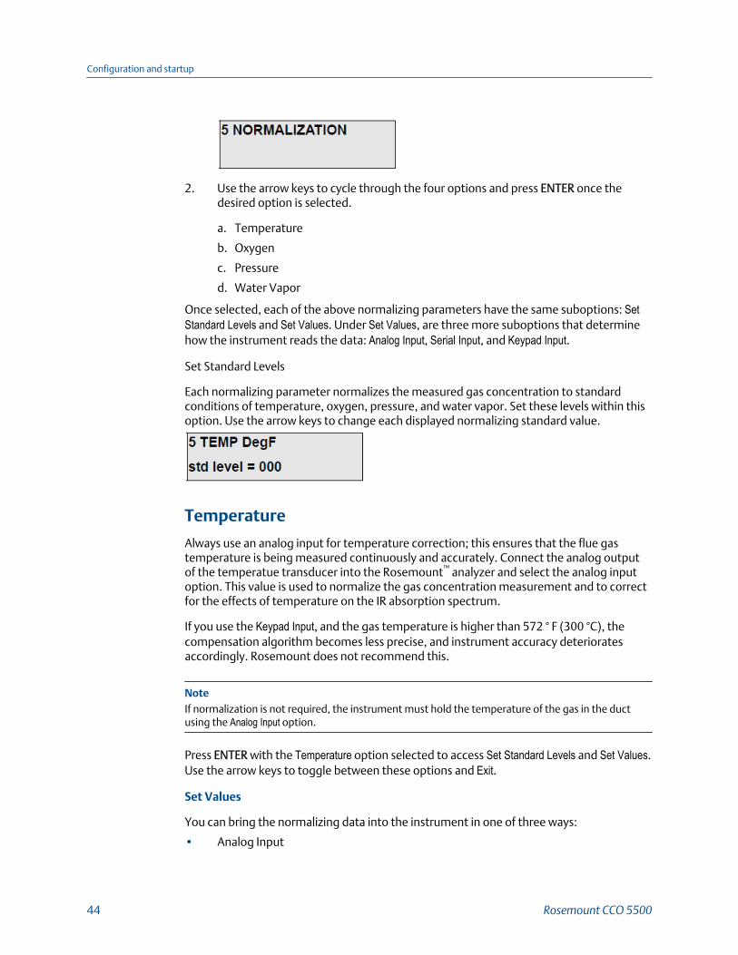
2. Use the arrow keys to cycle through the four options and press ENTER once thedesired option is selected.
a. Temperature
b. Oxygen
c. Pressure
d. Water Vapor
Once selected, each of the above normalizing parameters have the same suboptions: SetStandard Levels and Set Values. Under Set Values, are three more suboptions that determinehow the instrument reads the data: Analog Input, Serial Input, and Keypad Input.
Set Standard Levels
Each normalizing parameter normalizes the measured gas concentration to standardconditions of temperature, oxygen, pressure, and water vapor. Set these levels within thisoption. Use the arrow keys to change each displayed normalizing standard value.
Temperature
Always use an analog input for temperature correction; this ensures that the flue gastemperature is being measured continuously and accurately. Connect the analog outputof the temperatue transducer into the Rosemount™ analyzer and select the analog inputoption. This value is used to normalize the gas concentration measurement and to correctfor the effects of temperature on the IR absorption spectrum.
If you use the Keypad Input, and the gas temperature is higher than 572 ° F (300 °C), thecompensation algorithm becomes less precise, and instrument accuracy deterioratesaccordingly. Rosemount does not recommend this.
NoteIf normalization is not required, the instrument must hold the temperature of the gas in the ductusing the Analog Input option.
Press ENTER with the Temperature option selected to access Set Standard Levels and Set Values.Use the arrow keys to toggle between these options and Exit.
Set Values
You can bring the normalizing data into the instrument in one of three ways:
• Analog Input
Configuration and startup
44 Rosemount CCO 5500

This uses the 4-20 mA inputs within the processor to receive the measuredtransducer data. The values at 4 mA and 20 mA will be requested should this optionbe selected.
• Serial Input
If you use an input unit, all normalizing data can be transmitted via the serial dataline.
• You can enter a fixed value via the keypad. This is suitable where the value is stableto about ±5%.
With an integrated system, set the lead analyzer's normalizing parameters to the 4-20 mAinputs. Then set all the other analyzers to serial, and the normalization parameters aretransmitted down the serial data highway.
Oxygen
To correct the data to standard levels of oxygen, you must enter an estimate of the oxygenat the point of measurement. If the oxygen level is being continuously measured, connectthe analog output of the oxygen analyzer into the Rosemount™ CCO 5500 Analyzer andselect Analog Input. You must define this input as either WET or DRY depending on how themeasurement is made. After you define the wet or dry, you need to define the Analog Inputvalues; set the 4 mA and 20 mA values. If the oxgyen level is relatively constant through allfiring conditions, you may use a fixed keypad input.
With an integrated system, you can take the oxygen data to the instrument via the serialdata line.
NoteIf normalization is not required, you must set the normalizing parameters for oxygen in theinstrument.
Pressure
To correct the data to a standard pressure, normally 14.7 psi (101 kPa), you mustdetermine the pressure at the point of measurement. If the flue pressure is relativelyconstant through all firing conditions, then you may use a fixed keypad input. If thepressure, is not constant, measure it and bring it into the instrument via the 4-20 mAanalog input within the processor.
Configuration and startup
Reference Manual 45

NoteIf normalization is not required, set the normalizing parameters for pressure in the instrument to14.7 psi (101 kPa)(Standard Level and Keypad Input).
With an integrated system, you can take the pressure data to the instrument via the serialdata line.
Water VaporAn across the duct monitor measures the gas concentration under wet conditions. Unlike asampling system, the gas has not been preconditioned in any way before you make ameasurement.
When the water vapor is at a relatively fixed level, set the standard level to DRY tonormalize it to dry conditions. Use a fixed value in the keypad option representing theexpected water vapor produced for the fuel type. If the measurement is not to benormalized for water vapor, set the standard level to WET.
With an integrated system, you can take the water vapor data to the instrument via theserial data line.
3.7.6 Reset averages
NoteResetting averages causes the rolling average data to be cleared from memory.
You can reset the average values that are currently held in the four averaging stacks usingthis option; this ereases the current average that is held in all of the averaging stacks.Select this option by pressing ENTER and using the arrow keys. The instrument requestsconfirmation before the averages are reset.
NoteIf you select this option, all the data in the averaging stacks is reset, and the data for as much as 30days is lost.
3.7.7 CalibrateFrom this option, you may display the two detector levels and conduct a basic calibration.While in this mode, the gas cell is not moved; this gives an immediate response for settingup the detector levels. A Cal Factor that is calculated during a calibration routine sets thebasic calibration of the instrument. Press ENTER while this is displayed to see the followingoptions:
1. Set Detectors
Configuration and startup
46 Rosemount CCO 5500

2. Span Adjust
3. Calibrate
Set detectors
You can display both the D1 and D2 levels; you can also display saturation counts. To givean immediate response to any alterations that are required, the filters and gas cells are notmoved during this operation.
Refer to Section 3.5 for a discussion of the detector level and saturation count.
Span adjust
NoteRosemount™ initially sets the span factor at the factory; do not adjust it unless the instrumentsensitivity is suspected. In any case, Rosemount recommends that you record the orginal valuebefore making adjustments.
You can adjust instrument sensitivity if a known concentration of gas exists between thesource and receiver units and instrument sensitivity is supsected. If a problem arises,consult Rosemount.
You may need to adjust the span factor if you have fitted new gas cells or filters.
Calibrate
Re-enter the Mode 5 CALIBRATE menu and proceed to the Calibrate option.
You can calculate the basic calibration of the instrument from this routine. It is preferableto conduct this operation with the plant shut down to ensure a zero gas concentrationwithin the duct. If this is not possible, the instrument can calibrate to a known value of thegas concentration - the calibration target.
Configuration and startup
Reference Manual 47

Set the calibration target either to a known value of the gas concentration or to zero. Thenset the desired number of cycles over which the calibration factor is determined(Rosemount™ recommends a minimum of 30). Now run the calibration, and the display willshow a countdown during its execution. When the calibration is complete, the new CalFactor is displayed for about five seconds, and the instrument exits the calibration routine.
NoteYou must run the calibration routine during commissioning; otherwise, the instrument will not beable to calculate the true level of gas within the duct.
Do not run the calibration routine unless reasonable conditions exist in the duct. If it is notthe initial calibration, record the Cal Factor from the Parameters option before running thecalibration.
To aid configuration and to record any subsequent changes to the operating parameters, Table 3-1 lists all of the options available and can be used as a record of the operatingparameters.
Instrument SettingsTable 3-1:
Parameter Config
Averages
Seconds
Minutes
Hours
Days
Output
0 or 4 mA base
Units
Average
Configuration and startup
48 Rosemount CCO 5500

Instrument Settings (continued)Table 3-1:
Parameter Config
Fault condition
Parameters
Path length
Alarm source
Alarm units
Alarm levels
Normalization
Temperature
Standard level °F (°C)
I/P °F (°C) @ 4 mA
I/P °F(°C) at 20 mA
Keypad input °C (not ideal)
Serial input
Oxygen
Standard level %
Wet or dry gas
I/P % @ 4 mA
I/P % @ 20 mA
Keypad input %
Serial input
Pressure
Standard level psi (kPa)
I/P psi (kPa) @ 4 mA
I/P psi (kPa) @ 20 mA
Keypad input
Serial input
Water vapor
Standard level (wet %/dry
Keypad input %
Measured value
After the instrument calibrates, it calculates a cal factor; this determines the calibration ofthe instrument. The instrument displays the cal factor for a few seconds after calibrating,and you can also interrogate the cal factor from Mode 4 (DIAGNOSTIC mode). Enter the calfactor into the table below as a record of instrument operation.
Configuration and startup
Reference Manual 49

NoteRosemount™ obtained factory settings under the following conditions:
• 2 m path length
• Clean conditions
Calibration DataTable 3-2:
Detector outputs Factory Config
D2
D1
E1
E2
Calibration data
Cal factor
Span factor
Output calibration
Set zero
Set span
3.8 Current output calibrationNow set up the current output using a calibrated multimeter set to DC current, 20 mAmax. Conduct this procedure as follows:
NoteRosemount™ sets the current output at the factory; do not alter it.
Procedure
1. Connect the multimeter to the output terminals within the control unit terminals+mA and -mA.
2. Enter Mode 5 → Configure Output → Fault Condition → Set Zero and adjust the levelusing the arrow keys until 0 mA is recorded. Record the value in brackets on thedisplay in Table 3-2.
3. Enter Mode 5 → Configure Output → Fault Condition → Set Span and adjust the levelusing the arrow keys until 20 mA is recorded. Record the value in brackets on thedisplay in Table 3-2.
Configuration and startup
50 Rosemount CCO 5500

4 Operation
4.1 IntroductionAfter you configure the Rosemount™ CCO 5500, it measures the gas levels between thesource and receiver and produces an output proportional to the gas levels. An integral 32-character LCD display also shows the calculated levels.
The Rosemount CCO 5500 Analyzer allows you to interrogate the microprocessor toobserve the system parameters and to change them if required.
The Rosemount CCO 5500 uses a menu-based program; you can gain access to it by thekey panel mounted on the lid of the control unit (Figure 4-1).
Control Unit KeypadFigure 4-1:
A. 32-character liquid crystal displayB. KeypadC. Data valid and alarm LEDs
4.1.1 MeasurementOnce the analyzer has completed configuration, it measures the absorption of IR radiationand calculates a parameter Y.
Operation
Reference Manual 51

Refer to Section A.7. The analyzer uses this value to produce a final concentration of gasthat can be normalized to standard conditions and averaged over a time ranging from 10seconds to 30 days.
The instrument computes four averages, any of which can be used to drive the analogoutput or displayed on the integral 32-character LCD.
4.1.2 CalibrationDuring the configuration procedure, the analyzer conducts a calibration that sets thesystem gains to produce a zero or known gas level. Once the analyzer has conducted theroutine, precision filters, which do not change, fix the calibration of the instrument .
4.2 Startup and operationPower up the system and wait for 30 minutes. This allows time for the infrared source toheat up. Once the receiver is detecting a signal, you will see a reading on the control unitdisplay. This should be in normal OPERATING mode, Mode 1 (shown by a number 1 at thetop left corner of the LCD); the display also shows a reading in vpm, mg/m3, or Nmg/m3. Ifthis appears, the system is functioning properly.
4.3 Modes of operationThe instrument has six modes of operation identified by a number in the top left corner ofthe display.
Mode 1: Operating Mode
Displays average gas concentration.
Mode 2: Parameters
Displays operating parameters.
Mode 3: Normalization
Displays normalization data.
Mode 4: Diagnostics
Investigates instrument operation. The instrument continually checks itself; if acomplicaiton exists, the instrument automatically selects this mode and displays the faulton the display.
Mode 5: Set up Mode
Sets operating parameters. You must enter the opening parameters for the instrument tofunction correctly. You can only access this mode using a security code.
Operation
52 Rosemount CCO 5500
Mode 6: Check Cell Mode
Used to verify the instrument's operation and calibration.
NoteThe outputs of the instrument are unaffected by key operation in all modes except the Set up mode.
4.4 Keypad operationYou can access each mode sequentially by each push of the MODE key.
Figure 4-1 illustrates the display and keys of the control unit. After you select a mode, usethe arrow keys to select the various options within these modes. Use the ENTER key toinput the displayed value and step the cursor to the next option where applicable.
1. MODE key: Press the MODE key to either take the instrument to the next mode ofoperation or back to the OPERATING mode if pressed from within a mode.
2. Arrow keys: Press the arrow keys to do one of two things, depending on the positionin the program:
• It increases ↑ or decreases ↓ the displayed value. If you hold down the key, itscrolls quickly to the desired value.
• It steps through the available options within a mode or submode.
3. ENTER key: Press the ENTER key to do one of two things, depending on the positionin the program:
• It inputs the displayed parameter value.
• It selects the displayed mode or option from within a mode or submode.
NoteAllow time for the instrument to respond to a key instruction; otherwise, it may record a double keyentry.
4.5 Menu treeFigure 4-2 shows the arrangement of the Rosemount™ CCO 5500 Analyzer menu tree.
Operation
Reference Manual 53

Rosemount CCO 5500 Analyzer Menu TreeFigure 4-2:
Operating mode
Parameters
Normalization
Diagnostics
Set up mode
vpm, mg/m3, mg/Nm3, Measure, Normalized, Sec, Min, Hour, Day
Identification
Parameters
Averages
Output alarmPlant statusExit
Analyzer typeEPROM program IDIdentity number
Path lengthSpan factorO/P fault
Sec, Min, Hour, Day
On, OffPlant St. I/P Temperature threshold
Oxygen thresholdWater vapor thresholdTemperature
OxygenPressureWater vaporExit
Detector outputsMod. FrequencyYval & CO ppmCalibration dataFault conditionExit
Security code
Set averages
Configure O/P
0000 to 9999
Seconds
Minutes
Hours
Days
Exit
10 to 60 s @ 10 s intervals
01 to 60 m @ 01 m intervals
01 to 24 h @ 01 h intervals
01 to 30 d @ 01 d intervals
Output
Average
Units
Set span
Fault condition
Set mA O/P
Exit
(0 or 4) to 20
Sec, Min, Hour, Day
vpm, mg/m3, mg/Nm3
0 to 9999 span
Zero, Mea, Hold, F.S.
Set zeroSet span
Operation
54 Rosemount CCO 5500

Set up mode
Check cell mode
Parameters
Normalization
Reset averages
Calibrate
Security
Identity
Path length
Alarm
Cal. factor
Plant St. I/P
Exit
4 digit code
01 to 30
Gas path length in mm
Source
UnitsAlarm level (0 to 9999)
0 to 9999
LogicSerialMultipleExit
Sec, Min, Hour, Day
Vpm, mg/m3, mg/Nm3
Temperature
Oxygen
Water vapor
Det. level
Logic
Yes, No
Yes, No
Yes, No
Yes, No
Yes, No
Temperature
Oxygen
Pressure
Water vapor
Exit
Set std. levelsSet valuesExit Analog input
Serial inputKeypad inputExit
Set std. levelsSet valuesExit
Set std. levelsSet valuesExit
Set std. levelsSet valuesExit
Analog inputSerial inputKeypad inputExit
Analog inputSerial inputKeypad inputExit
Serial inputKeypad inputExit
Yes, No
Set detectorsSpan adjustCalibrateExit
Yes, No
4.6 Operating modeFrom this mode of operation, you may alter the averaging time of the displayed gasconcentration to one of the other averaging stacks and observe the measured/normalizedgas measurements. When in this mode, the display appears similar to that shown below. Ifthe display is not similar to this, press MODE until number 1 appears at the top left cornerof the display.
Operation
Reference Manual 55

To change the data displayed, press ENTER, and a flashing cursor appears at the beginningof the concentration units, i.e., vpm or mg/Nm3. The arrow keys now change thehighlighted parameter. Each push of ENTER selects another of the parameters in thefollowing order:
1. Concentration units: vpm, mg/m3 (or mg/Nm3).
2. Measured or normalized display.
3. Averaging time: seconds, minutes, hours, or days.
Press ENTER when the cursor is flashing on the averaging time, and the cursor disappearsfrom the display. You may press ENTER again if required to bring the cursor back onto thedisplay.
4.7 ParametersIn this mode, you can examine the parameters set within the SET UP mode, but you cannotchange them. Press MODE until the number 2 appears in the top left corner of the display;then press ENTER. Use the arrow keys to scroll through the available options; press ENTERto display one of the selected options below.
1. Identification
2. Parameters
3. Averages
4. Output Alarm
5. Plant Status
Press ENTER again to exit from each option.
Refer to Section 4.10 for further details of the display information and how to change theheld parameters.
4.7.1 IdentificationYou can display the analyzer type, identity number, and EPROM program ID from thisoption. Use the arrow keys to scroll between these options.
4.7.2 ParametersYou can display the following parameters from this option; select them using the arrowkeys.
1. Path Length: The path length currently used to calculate the gas calculation.
Operation
56 Rosemount CCO 5500

2. Span Factor: You can adjust the sensitivity of the instrument from the SET UP mode→ CALIBRATE option. Rosemount™ initially set the span factor at the factory usingknown gas concentrations.
3. O/P (Output) Fault: Should a fault condition occur, you can set the analog input fromone of four options.
4.7.3 AveragesSelect this option to display the times set for each of the four averaging stacks: seconds,minutes, hours, and days.
4.7.4 OutputYou can display the base, span, and averaging of the analog output from this option.
4.7.5 AlarmA changeover relay contact output is available to indicate a high gas concentration. Youcan examine the level at which the output is operated and the averaging stack from whichthe gas value is obtained from this display.
4.7.6 Plant statusWhen plant status is OFF, the minutes, hours, and days averaging stacks do not update.
NoteWhen the plant status is OFF, pollutant levels are zero. It is not normally permitted to use plant OFFzero levels to reduce the recorded mean entitled pollutant levels.
You can use this function to ensure data is only collected when the plant is fullyoperational. You can use three options to determine plant status ON or OFF: Logic Input,Serial Input, and Multiple. Multiple has four options: Temperature threshold, Oxygen threshold, WaterVapor threshold, and Logic Input. You can view the plant status and its governing factor fromthis display.
4.8 NormalizationComplete the following steps to display and/or edit the normalization parameters for theanalyzer.
1. Press MODE until you see the number 3 in the top left corner of the display.
From this mode, you can display the normalization parameters currently used.
2. Press ENTER to enter the routine and use the arrow keys to select which of thenormalizing parameters to display.
Operation
Reference Manual 57

Listed below are the four normalizing parameters accessible through this mode:
a. Temperature
b. Oxygen
c. Pressure
d. Water Vapor
3. When you see the required normalizing parameter, press ENTER to display thenormalization data. Press ENTER again to exit the parameter.
For each of the four normalizing parameters, the display appears similar to thatshown below.
Normalization ExampleFigure 4-3:
A. Selected parameterB. UnitsC. Standard level required (wet or dry for water vapor)D. Parameter source
• k = keypad input• a = analog input• s = serial data input• m = measured input
4.9 Diagnostic modeYou may examine the detector levels, chopper blade frequency, Y parameter, and the faultcondition from this mode. Press MODE until the number 4 appears in the top left corner ofthe display and press ENTER to access this mode. Once in Diagnostics, the five suboptionsare as follows:
1. Detector outputs
2. Modulation Frequency
3. Yval and CO ppm
4. Calibration Data
5. Fault Conditions
4.9.1 Detector outputsThis mode displays detector levels from the detector. D1 is the reference level and shouldalways be less than D2. The level of D2 should be between 10,000 and 20,000.
Operation
58 Rosemount CCO 5500

E1 and E2 are the detector levels with the gas cell within the source unit in the sight pathand will be roughly ½ of the D2 and D1 levels. The analyzer may also display smootheddetector values; these are noted as d1, d2, e1, and e2.
Sat. # indicates whether the detector signals are saturating within the micro-processor(this value should always be zero). If it displays a number other than zero, it indicatessaturation, and you should adjust the detector gain. Refer to Section 3.5.
Phase is the time correction applied for the calculation of the detector levels. This will bebetween 0.1 and 5.9 milliseconds. The instrument calculates this value, and you may notadjust it.
4.9.2 Modulation (chopper motor) frequencyThe chopper blade should chop the IR radiation at a frequency of about 37 Hz. Theprocessor measures this frequency and displays it from this option.
As the chopper blades interrupt the IR beam, they split the radiation into two. Half thetime the blade obscures the beam, and half the time the beam radiates across the duct.The value of Mark/space should be between 0.9 and 1.1 where:
Mark/space = Time IR beam obscured/Time IR beam clear.
4.9.3 YVals and CO ppmA parameter Y determines the calculation of the gas concentration; refer to Section A.7.5.
As a check on the program operation, you may view this parameter and the resulting rawgas calculation here.
The term Yx is the second averaging stack's held value, and the term Y(60) is the 60-second raw value from which all of the other averaging stacks are calculated. These gasvalues represent the raw data before averaging for the corresponding Y values. You canalso display the Z values by pressing the arrow keys. The Z values are the adjusted Y valuesused to compensate for cross sensitivities in the measurement range.
Operation
Reference Manual 59

4.9.4 Calibration dataYou can examine the calibration factors determined during the calibration routine (SCcal)and the value currently being used (SCwkg) from this display. If the two values aredifferent, this indicates a change in instrument temperature between the time ofcalibration and the current temperature. Press one of the arrow keys to examine thetemperature information.
Temperature has a small effect on the filter/gas cell characteristics compensated for by theinstrument. Temperature measurement is made within the receiver.
4.9.5 Fault conditionTo display the current fault condition, press ENTER while this is displayed.
The instrument automatically selects this display mode if a fault condition occurs. Theinstrument recognized the following fault conditions:
1. ALL CLEAR: No fault condition.
2. Det. Saturated: The detector level gain within either the receiver or the control unitis too high for the current duct conditions.
3. Low Det. Level: Detector levels are too low (< 3,000).
4. Mod. Freq.O.R.: Chopper motor frequency is out of range (< 30 Hz or > 45 Hz).
5. Reference Fail.: No reference signal from the source unit.
6. Cal. Fact. O.R.: After the calibration routine, the calculated Set Cal factor is out ofrange. Refer to Chapter 6.
Press the arrow key to observe the previous fault condition.
NoteIf a fault condition exists, the instrument does not update the minutes, hours, and days averages.Refer to Section 6.1.1.
Operation
60 Rosemount CCO 5500

4.10 Set up modeYou can change all operating parameters (averaging times, output settings, normalizationparameters, path length, calibration, etc.) from this mode. To prevent any unauthorizedchanges, you must enter a four digit code before you can enter this mode.
NoteAfter you select this mode, the instrument suspends its operation and extinguishes the Data ValidLED. If you don't press a key within five seconds after selecting this mode, the Rosemount™ CCO5500 Analyzer will revert to the normal OPERATING mode.
Rosemount recommends that you complete Table 4-1 to provide a record of theinstrument setup in order to aid configuration and to record any subsequent changes tothe operating parameters.
Press MODE until the number 5 is displayed in the top left corner. After you have correctlyentered the security code, there are six submodes of operation from which you can changethe setup parameters. These six submodes are listed below:
1. Set Averages: You may set the four averaging stack times (seconds, minutes, hours,and days) as required.
2. Configure O/P: Analog output setup: origin, units, span, rolling average, and faultcondition.
3. Parameters: You may set the following from this mode: security code, identitynumber, path length, alarm level, cal factor, and plant status.
4. Normalization: You may set up all normalization parameters from this mode.
5. Reset Average: Select this submode to reset the four averaging stacks.
6. Calibrate: You can set the outputs of the detectors and the basic calibration of theinstrument.
Use the arrow keys to toggle between these six options and press ENTER when the desiredoption is displayed.
4.10.1 Enter security codeComplete the following steps to enter the security code.
1. Once the display is as shown here, press ENTER to gain access to SET UP mode.
The cursor flashes over the first digit of the security code number.
2. Select the required first digit with the arrow keys and press ENTER.
3. Repeat this procedure for the remaining three numbers.
Operation
Reference Manual 61

If the code is correct after you press ENTER on the last digit, the sequence iscontinued. If it is not correct, the instrument returns to OPERATING mode. Refer to Section 3.7.4 for further details.
NoteRosemount™ sets the code number to 0000 at the factory; you should change it in SET UPmode.
4.10.2 Set averagesThe instrument calculates four separate averages. These are defined in units of seconds,minutes, hours, and days. You can use any of the four averaging stacks to provide theinstrument's analog output. You can set each averaging time within predefined limits.
1. Press ENTER when this display is shown.
The display now shows one of the averages.
2. Use the arrow keys to select the average time that you need to change and pressENTER to change it.
You can now change the value using the arrow keys and confirm it by pressingENTER.
3. Set the seconds averaging stack to the required value.
This is limited to within 10 to 60 seconds in 10-second intervals.
4. Set the minutes averaging stack to the required value.
This is limited to within 1 to 60 minutes in 1-minute intervals.
5. Set the hours averaging stack to the required value.
This is limited to within 1 to 24 hours in 1-hour intervals.
6. Set the days averaging stack to the required value.
Operation
62 Rosemount CCO 5500
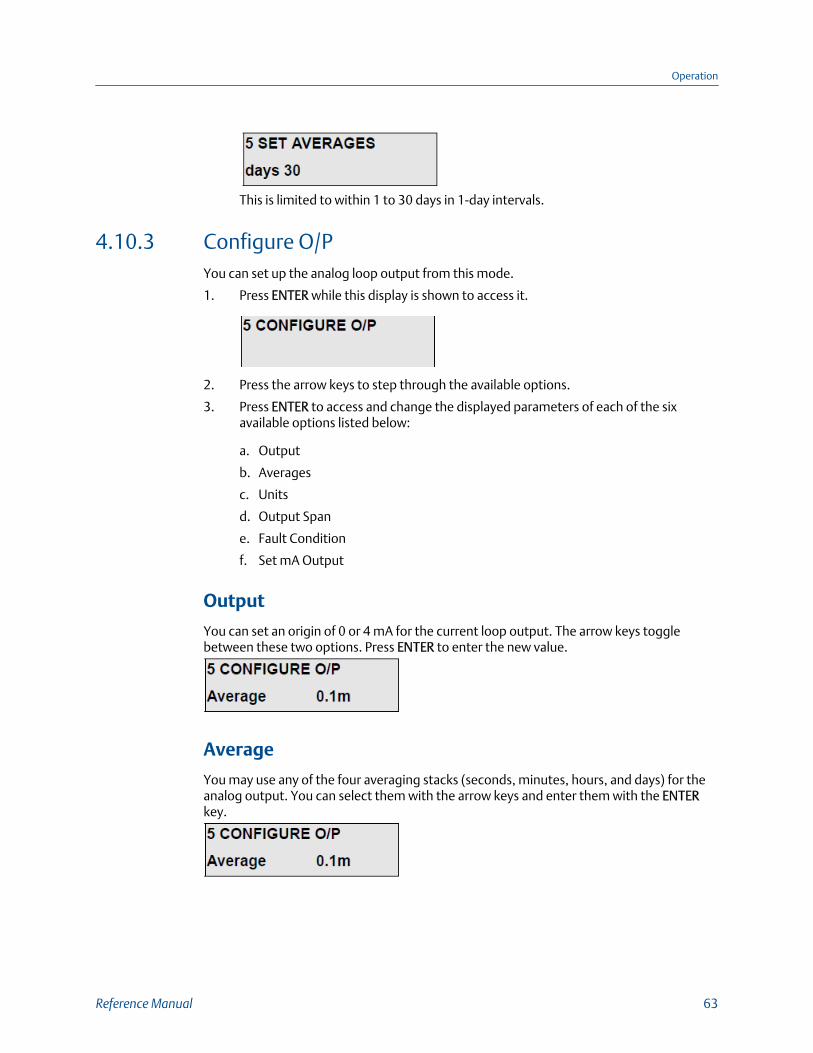
This is limited to within 1 to 30 days in 1-day intervals.
4.10.3 Configure O/PYou can set up the analog loop output from this mode.
1. Press ENTER while this display is shown to access it.
2. Press the arrow keys to step through the available options.
3. Press ENTER to access and change the displayed parameters of each of the sixavailable options listed below:
a. Output
b. Averages
c. Units
d. Output Span
e. Fault Condition
f. Set mA Output
Output
You can set an origin of 0 or 4 mA for the current loop output. The arrow keys togglebetween these two options. Press ENTER to enter the new value.
Average
You may use any of the four averaging stacks (seconds, minutes, hours, and days) for theanalog output. You can select them with the arrow keys and enter them with the ENTERkey.
Operation
Reference Manual 63

Units
The analog output can represent the gas concentration in units of mg/m3, mg/Nm3, orvpm. The arrow keys toggle between these three options. Press ENTER to enter the newvalue.
Output Span
Select the required span using the arrow keys for each digit. Press ENTER to enter the valueof each digit. The units are displayed in vpm, mg/m3, or mg/Nm3, depending on what hasbeen selected beforehand.
NoteOnce you select Output Span, the current value is displayed for one second. The first digit of thedisplay then defaults to zero; thus you must re-enter the span value for the unit to function correctly.
Fault conditionIf a fault condition occurs, you may set the current output of the instrument to one of thefollowing options:
Procedure
1. Set the output at 0 mA - ZERO.
2. Adjust the output to the calculated gas concentration even though a fault conditionexists - MEAS.
3. Hold the last selected gas concentration - HOLD.
4. Set the output to full scale (20 mA) - F.S.
Press the arrow keys to select one of these options; when the desired output is displayed,press ENTER to confirm.
Set mA output
NoteThis is set at the factory and should not be altered without due consideration.
Operation
64 Rosemount CCO 5500

From this option, the current levels of the analog output are set up. Press ENTER to selectit, and the instrument prompts you to set the current levels at 0 and 20 mA.
When this is displayed, set the current output to 0 mA as measured with a calibratedcurrent meter across the analog ouput loop terminals; do not connect anything else tothese terminals when setting up the output.
Use the two arrow keys to adjust the value; the UP arrow takes the current output up, andthe DOWN arrow takes it down. Press ENTER when the correct output is displayed on theammeter.
NoteZero mA should be set up no matter what has been selected as the base of the current output. This isfactory set.
In a similar manner to the above, set the current output level to 20 mA.
4.10.4 ParametersComplete the following steps to set the parameters.
1. With this option displayed, press ENTER to access the list of six available options.
The arrow keys cycle through these options.
2. When the option you need to change is displayed, press ENTER.
3. When you have made all required changes, select EXIT and press ENTER.
The six available options are:
a. Security Number
b. Identity Number
c. Path Length
d. Alarm
e. Cal. Factor
f. Plant Status Input
Operation
Reference Manual 65

Security NumberTo prevent any unauthorized tampering with the setup information, it is important tochange the security code from the factory setting.
Select each digit with ENTER and change it with the arrow keys.
NoteIt is important to make note of this number; otherwise, it will not be possible to change theinstrument set up.
Identity Number
If you are using the system as part of an integral monitoring system and are using the serialinput and outputs, the central processor requires a Device Identity to identify eachinstrument. This number must be unique for each equipment item and can be set from 1to 30 as required.
Path Length
NoteOnce you select path length, the instrument displays the current value for one second. The first valueof the display then defaults to zero; therefore, you must re-enter the value to calculate the gasconcentrations correctly.
The transmissivity of any gas depends both on the concentration and on the path lengththrough which the radiation is transmitted. Similarly, the output of the Rosemount™ CCO5500 Analyzer gas monitor also depends on the path length of the flue gas through whichthe radiation is transmitted.
Refer to Section 2.4.1.
The Rosemount CCO 5500 Analyzer is sensitive to the product of concentration and pathlength. In order to obtain a true value of concentration of gas, you must input the correctpath length into the processor. The processor then uses the value to produce a final valueof gas concentration.
NoteThe path length entered must represent the length of the actual gas pass, not the flange to flangedimension between the source and receiver.
Operation
66 Rosemount CCO 5500

Alarm
A contact output is available to warn of a high gas concentration. You may trigger thecontact output from any of the four averaging stacks. Select the source with the arrow keyand enter it with ENTER.
Select the units for the alarm; these may be different than the units selected for the analogoutput.
After you select the source, the instrument requires a level that will trigger the output. Setthe desired level with the arrow keys.
Cal Factor
NoteFirst, record the original Cal Factor before entering this mode as displayed in Mode 4 → CalibrationData. The Cal Factor is lost when the menu option is entered.
During the calibration routine, the instrument calculates a Cal Factor which sets the basiccalibration of the instrument. You may change this value from this mode.
NoteSince this value controls the calibration of the instrument, only change if necessary.
Plant Status InputUse this to determine whether the plant is operating under correct conditions.
There is a choice of three controls for plant status: Logic Input, Serial Input, and Multiple. Youcan only use one to control plant status at any one time.
Operation
Reference Manual 67

• Logic Input
If the PS1 and PS2 terminals are linked in the control unit, the logic contact is made,and the plant status is OFF. You may link these terminals manually during a plantshut down, or you may wire them to a switch/contact outside the unit (e.g., a valuethat opens and closes the duct). Press ENTER to select this option when the PlantStatus → Serial Input option is displayed.
• Serial input
If you select this option, the criteria controlling plant status are transmitted via theserial data link. Press ENTER when the Plant Status I/P → Serial Input option isdisplayed to select this option.
• Multiple
Four options are available here. Press ENTER when the Plant Status I/P → Multipleoption is displayed, and the first option Temperature is displayed. Use the arrow keysto toggle YES or NO. NO means that the temperature threshold is not used todetermine plant status. If you select YES, the display enters the display below.Configure the instrument for temperature threshold. Press ENTER when it iscorrectly configured, and the display moves to the next option Oxygen. After you setthe last option, the Logic Input display returns to the PARAMETERS → Plant Status I/Poption. Use the DOWN arrow to scroll down to EXIT and press ENTER. The plantstatus is now full configured.
Plant status is only OFF if all options selected are registering plant status OFF. If anyone of them is not fulfilling plant status OFF conditions, then the instrumentregisters plant status ON.
- Temperature
A value is set here for the temperature threshold. While the temperature (takenfrom the normalizing temperature) is above the threshold value, plant status isON. If the temperature drops below the threshold, plant status is OFF, and onlythe seconds averaging stack updates.
- Oxygen
Oxygen is set and used in a similar manner to the temperature threshold.However, if the normalizing oxygen level rises above the threshold, plant statusis OFF. For plant status ON, the oxygen level must be below the threshold.
- Water Vapor
Operation
68 Rosemount CCO 5500

This is set and used in a similar manner to the temperature threshold. If thenormalizing water vapor level falls below the threshold, plant status is OFF. Forplant status ON, the water vapor level must be above the threshold.
- Logic Input
Select YES or NO and press ENTER. For plant status to be ON, the logic input (PS1and PS2) must be open circuit; for plant status to be OFF, the logic input must beclosed circuit. After you configure this option, the menu exits to the Multipleoption. Use the DOWN arrow to select EXIT and press ENTER.
4.10.5 NormalizationComplete the following steps to set the Normalization parameters.
1. Press ENTER to access one of the four normalizing parameters listed below.
2. Use the arrow keys to cycle through the four options and press ENTER once thedesired option is selected.
a. Temperature
b. Oxygen
c. Pressure
d. Water Vapor
Once selected, each of the above normalizing parameters have the same suboptions: SetStandard Levels and Set Values. Under Set Values, are three more suboptions that determinehow the instrument reads the data: Analog Input, Serial Input, and Keypad Input.
Set Standard Levels
Each normalizing parameter normalizes the measured gas concentration to standardconditions of temperature, oxygen, pressure, and water vapor. Set these levels within thisoption. Use the arrow keys to change each displayed normalizing standard value.
Temperature
Always use an analog input for temperature correction; this ensures that the flue gastemperature is being measured continuously and accurately. Connect the analog outputof the temperatue transducer into the Rosemount™ analyzer and select the analog inputoption. This value is used to normalize the gas concentration measurement and to correctfor the effects of temperature on the IR absorption spectrum.
Operation
Reference Manual 69

If you use the Keypad Input, and the gas temperature is higher than 572 ° F (300 °C), thecompensation algorithm becomes less precise, and instrument accuracy deterioratesaccordingly. Rosemount does not recommend this.
NoteIf normalization is not required, the instrument must hold the temperature of the gas in the ductusing the Analog Input option.
Press ENTER with the Temperature option selected to access Set Standard Levels and Set Values.Use the arrow keys to toggle between these options and Exit.
Set Values
You can bring the normalizing data into the instrument in one of three ways:
• Analog Input
This uses the 4-20 mA inputs within the processor to receive the measuredtransducer data. The values at 4 mA and 20 mA will be requested should this optionbe selected.
• Serial Input
If you use an input unit, all normalizing data can be transmitted via the serial dataline.
• You can enter a fixed value via the keypad. This is suitable where the value is stableto about ±5%.
With an integrated system, set the lead analyzer's normalizing parameters to the 4-20 mAinputs. Then set all the other analyzers to serial, and the normalization parameters aretransmitted down the serial data highway.
Oxygen
To correct the data to standard levels of oxygen, you must enter an estimate of the oxygenat the point of measurement. If the oxygen level is being continuously measured, connectthe analog output of the oxygen analyzer into the Rosemount™ CCO 5500 Analyzer andselect Analog Input. You must define this input as either WET or DRY depending on how the
Operation
70 Rosemount CCO 5500

measurement is made. After you define the wet or dry, you need to define the Analog Inputvalues; set the 4 mA and 20 mA values. If the oxgyen level is relatively constant through allfiring conditions, you may use a fixed keypad input.
With an integrated system, you can take the oxygen data to the instrument via the serialdata line.
NoteIf normalization is not required, you must set the normalizing parameters for oxygen in theinstrument.
Pressure
To correct the data to a standard pressure, normally 14.7 psi (101 kPa), you mustdetermine the pressure at the point of measurement. If the flue pressure is relativelyconstant through all firing conditions, then you may use a fixed keypad input. If thepressure, is not constant, measure it and bring it into the instrument via the 4-20 mAanalog input within the processor.
NoteIf normalization is not required, set the normalizing parameters for pressure in the instrument to14.7 psi (101 kPa)(Standard Level and Keypad Input).
With an integrated system, you can take the pressure data to the instrument via the serialdata line.
Water VaporAn across the duct monitor measures the gas concentration under wet conditions. Unlike asampling system, the gas has not been preconditioned in any way before you make ameasurement.
When the water vapor is at a relatively fixed level, set the standard level to DRY tonormalize it to dry conditions. Use a fixed value in the keypad option representing theexpected water vapor produced for the fuel type. If the measurement is not to benormalized for water vapor, set the standard level to WET.
With an integrated system, you can take the water vapor data to the instrument via theserial data line.
4.10.6 Reset averages
NoteResetting averages causes the rolling average data to be cleared from memory.
Operation
Reference Manual 71

You can reset the average values that are currently held in the four averaging stacks usingthis option; this ereases the current average that is held in all of the averaging stacks.Select this option by pressing ENTER and using the arrow keys. The instrument requestsconfirmation before the averages are reset.
NoteIf you select this option, all the data in the averaging stacks is reset, and the data for as much as 30days is lost.
4.10.7 CalibrateFrom this option, you may display the two detector levels and conduct a basic calibration.While in this mode, the gas cell is not moved; this gives an immediate response for settingup the detector levels. A Cal Factor that is calculated during a calibration routine sets thebasic calibration of the instrument. Press ENTER while this is displayed to see the followingoptions:
1. Set Detectors
2. Span Adjust
3. Calibrate
Set detectors
You can display both the D1 and D2 levels; you can also display saturation counts. To givean immediate response to any alterations that are required, the filters and gas cells are notmoved during this operation.
Refer to Section 3.5 for a discussion of the detector level and saturation count.
Span adjust
NoteRosemount™ initially sets the span factor at the factory; do not adjust it unless the instrumentsensitivity is suspected. In any case, Rosemount recommends that you record the orginal valuebefore making adjustments.
Operation
72 Rosemount CCO 5500

You can adjust instrument sensitivity if a known concentration of gas exists between thesource and receiver units and instrument sensitivity is supsected. If a problem arises,consult Rosemount.
You may need to adjust the span factor if you have fitted new gas cells or filters.
Calibrate
Re-enter the Mode 5 CALIBRATE menu and proceed to the Calibrate option.
You can calculate the basic calibration of the instrument from this routine. It is preferableto conduct this operation with the plant shut down to ensure a zero gas concentrationwithin the duct. If this is not possible, the instrument can calibrate to a known value of thegas concentration - the calibration target.
Set the calibration target either to a known value of the gas concentration or to zero. Thenset the desired number of cycles over which the calibration factor is determined(Rosemount™ recommends a minimum of 30). Now run the calibration, and the display willshow a countdown during its execution. When the calibration is complete, the new CalFactor is displayed for about five seconds, and the instrument exits the calibration routine.
NoteYou must run the calibration routine during commissioning; otherwise, the instrument will not beable to calculate the true level of gas within the duct.
Operation
Reference Manual 73
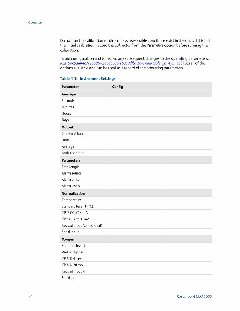
Do not run the calibration routine unless reasonable conditions exist in the duct. If it is notthe initial calibration, record the Cal Factor from the Parameters option before running thecalibration.
To aid configuration and to record any subsequent changes to the operating parameters, #xd_5bc5da84c7ce5b06--2a6d55ac-163c9dfb12c--7ead/table_jlb_4y5_b2b lists all of theoptions available and can be used as a record of the operating parameters.
Instrument SettingsTable 4-1:
Parameter Config
Averages
Seconds
Minutes
Hours
Days
Output
0 or 4 mA base
Units
Average
Fault condition
Parameters
Path length
Alarm source
Alarm units
Alarm levels
Normalization
Temperature
Standard level °F (°C)
I/P °F (°C) @ 4 mA
I/P °F(°C) at 20 mA
Keypad input °C (not ideal)
Serial input
Oxygen
Standard level %
Wet or dry gas
I/P % @ 4 mA
I/P % @ 20 mA
Keypad input %
Serial input
Operation
74 Rosemount CCO 5500

Instrument Settings (continued)Table 4-1:
Parameter Config
Pressure
Standard level psi (kPa)
I/P psi (kPa) @ 4 mA
I/P psi (kPa) @ 20 mA
Keypad input
Serial input
Water vapor
Standard level (wet %/dry
Keypad input %
Measured value
After the calibration is conducted, a cal factor is calculated; this determines the calibrationof the instrument. The cal factor is displayed for a few seconds after a calibration has beenconducted, and you can aslo interrogate it from Mode 4 (DIAGNOSTIC mode). Enter the calfactor into the table below as a record of instrument operation.
NoteRosemount™ obtained factory settings under the following conditions:
• 2 m path length
• Clean conditions
Calibration DataTable 4-2:
Detector outputs Factory Config
D2
D1
E1
E2
Calibration data
Cal factor
Span factor
Output calibration
Set zero
Set span
Operation
Reference Manual 75

4.11 Check Cell modeUse this mode with a Rosemount™ check cell. It verifies calibration and operation of theanalyzer.For details for this mode's use, refer to Section 4.13.1.
Procedure
1. Press ENTER on viewing this display if you need to use the CHECK CELL mode.
2. Use the arrow keys to toggle the display to YES and press ENTER again.
You have now selected the CHECK CELL mode. Note that the display will default backto Mode 1 if you don't select YES within five seconds. Do not insert a the check cellbefore accessing this option. Refer to Section 4.13.1.
4.12 Shutdown procedureYou do not need to shut down the system unless you are performing maintenance.
1. In this case, power down the power supply (and thus the control unit and analyzerheads).
2. Close the manually operated isolating valves on the analyzer heads.
3. Proceed with service.
4. When completed, open the valves and power up the system.
Postrequisites
You may need to calibrate the system depending on the type of maintenance you aredoing. For details, refer to Chapter 6
4.13 Routine checks
4.13.1 Notes for using a Rosemount™ check cellThe check cell and holder are optional items available from Rosemount. Rosemount hasdesigned the check cell to verify the reading of Rosemount cross duct analyzers. Whenplaced within the measurement path, the check cell can generate a known increase in gasconcentration.
Operation
76 Rosemount CCO 5500

Prerequisites
NotePlace the check cell at the receiver side.
Measurement conditions
For absolute verification, you must check the instrument when no measurement gas ispresent. If a background concentration of measurement gas is present, an increase will stillbe generated, but the net effect will be complex.
Mode 6
The ideal time to perform a check cell test is with the plant off, auto zero condition on, andthe analyzer well stabilized at zero. Do not insert the check cell in any other mode thanMode 6.
The analyzer does not update rolling averages while in Mode 6.
Procedure
1. Enter Mode 6 on the control unit before inserting the check cell into the analyzer.Press ENTER when Mode 6 is displayed.
2. Use an arrow key to toggle from NO to YES and press ENTER to access the check cellfunction.
If you don't select this within five seconds, the instrument returns to the normalOPERATING mode.
3. When you see this option, insert the check cell observing the procedure outlinedbelow.
4. Remove the two screws retaining the cover on the check cell holder (Figure 4-4).
Operation
Reference Manual 77

Check Cell HolderFigure 4-4:
A. Check cell coverB. ReceiverC. Check cell holder
5. Insert the check cell into the check cell holder and replace and tighten the screws.
You can insert the cell in either direction. Refer to Figure 4-5.
Check CellFigure 4-5:
A. Gas cell window
Introducing the check cell may cause an initial major disturbance to the instrumentoperation.
6. Wait for the instrument reading to settle (five to ten minutes) and record the gasmeasurement with the cell in position.
7. Remove the check cell and wait for the analyzer to return to zero (another five to tenminutes).
8. Replace the cover on the check cell holder and place MODE on the control unit.
The instrument now returns to OPERATING mode.
Operation
78 Rosemount CCO 5500

You can do this test with the plant on line, but any pollutant gas present (it will probably beresiding at a different temperature) will interfere with the check cell value.
NoteDo not insert the check cell in any other mode as this will influence the recorded rolling averages.
Rosemount fixes the calibration of the Rosemount CCO 5500 Analyzer at the point ofmanufacture. If gross errors exist, this could suggest an instrument malfunction. If youobserve minor errors, please check the procedure and if necessary, return the gas cell forrecertification.
4.13.2 Alarms and emergency conditionsThe alarm thresholds for the system are set as described in the normal OPERATING mode.When an alarm condition occurs, the red LED on the control unit lights up. This goes outwhen the alarm condition has cleared. When the condition has cleared, the softwarerecords the fact that an alarm condition occurred. The 4 to 20 mA output from theanalyzer will also alter according to the pollution levels detected.
4.13.3 Emergency shutdown procedureThis is the same as normal shutdown.
1. Remove power from the power supply.
The whole system closes down.
2. Close the isolating valves if required and stop the flow of air to the air purges.
4.13.4 Isolation procedureComplete the following steps to isolate the analyzer.
1. Shut down power to the power supply.
2. Shut off compressed air to the air purges and close the isolating valves.
Operation
Reference Manual 79

Operation
80 Rosemount CCO 5500

5 Maintenance
5.1 Preventative maintenanceRosemount designs this equipment to keep maintenance to an absolute minimum.
5.1.1 Cleaning windowsIt is important that you keep the optical windows of both the source and receiverreasonably clean. Keep any mounting tubes free from build-up of dust and fly ash.Clean the optical window (Figure 5-1) every six months and more frequently for dirtyprocesses.
Optical WindowFigure 5-1:
A. Air purgeB. SourceC. Window
WARNING!
HIGH TEMPERATURE AND DANGEROUS VAPORSTake great care when removing the Rosemount™ CCO 5500 Analyzer from a positive pressurestack or duct. The source may be very hot, and there may be dangerous vapors present.Observe all required safety practices.
Procedure
1. Unbolt and remove the source and receiver from their air purges.
2. Wipe the windows with a soft dry cloth.
Maintenance
Reference Manual 81

5.2 Corrective maintenanceThe following maintenance procedures describe the necessary steps for removing andreplacing failed elements of the Rosemount™ CCO 5500 Analyzer.
WARNING!
ELECTRIC SHOCKInstall all protective equipment covers and safety ground leads after equipment repair orservice. Failure to install covers and ground leads could result in serious injury or death.
5.2.1 Replace heater elementThe heater element has a finite life and at some stage you will have to replace it.Rosemount™ designed the unit to give a minimum of two years continuous operation; youcan replace the heater element on site when necessary.Replace a failed heater element according to the following procedure.
Procedure
1. Shut down and lock out power to the Rosemount CCO 5500 Analyzer.
2. Unbolt and remove the source unit from the air purge.
3. Loosen the source unit cable gland (Figure 5-2) so the cable can slip when the rearcover plate is removed.
Source Rear Cover PlateFigure 5-2:
A. Rear cover plateB. Cable gland
4. Unsccrew and remove the rear cover plate.
5. Unscrew and remove the circuit board (Figure 5-3).
Maintenance
82 Rosemount CCO 5500

Source Unit Circuit BoardFigure 5-3:
A. Circuit board mounting screwB. Circuit board
6. Remove the terminal nuts (Figure 5-4) and remove the heater wires.
Heater ElementFigure 5-4:
A. Terminal nutsB. Captive screwC. Heater
7. Unscrew the three captive screws.
8. Remove and discard the heater assembly.
9. Install the new heater assembly and tighten the three captive screws.
Maintenance
Reference Manual 83

10. Install the two wires and terminal nuts removed in Step 6.
11. Install the circuit board and retaining screws removed in Step 5.
12. Install and fasten the rear cover plate.
13. Power up the Rosemount CCO 5500 Analyzer and allow fifteen minutes for theheater to reach operating temperature.
The analyzer starts to monitor the gas levels.
5.2.2 Replace chopper motor assemblyComplete the following steps to replace the chopper motor assembly in the analyzer.
1. Shut down and lock out power to the Rosemount™ CCO 5500 Analyzer.
2. Unbolt and remove the source unit from the air purge.
3. Remove the window plate (Figure 5-5) from the source unit.
Source Unit Circuit Board and Center Plate AssemblyFigure 5-5:
A. Black wire (M-)B. Red wire (M+)C. Window plateD. Circuit board and center plate assemblyE. Brass screws
Maintenance
84 Rosemount CCO 5500

4. Unscrew the three brass screws that secure the circuit board and center plateassembly.
5. Lift the circuit board and center plate assembly out of the source unit.
6. De-solder the red and black chopper motor power wires from the circuit board.
7. Unscrew and remove the three chopper motor screws (Figure 5-6).
Chopper Motor AssemblyFigure 5-6:
A. Chopper motor assemblyB. Chopper motor retaining screwsC. Center plate
8. Install the new chopper motor and retaining screws removed in Step 7.
9. Solder the chopper motor power wires to the circuit board. Solder the red wire tothe M+ terminal and the black wire to the M- terminal.
10. Install the center plate and circuit board assembly. Secure the assembly with thethree brass crews removed in Step 4.
11. Line up and install the window plate onto the source unit. Fully seat the windowplate flange in the source unit.
12. Secure the source unit to the air purge using the four screws removed in Step 2.Tighten the screws evenly.
13. Power up the Rosemount CCO 5500 Analyzer and check the chopper motorfrequency in Mode 4 (DIAGNOSTICS). Adjust using the trim potentiometer asdescribed in Section 3.6.
Maintenance
Reference Manual 85

5.2.3 Replace source unit gas cellReplace the source unit gas cell according to the following procedure.
1. Shut down and lock out power to the Rosemount™ CCO 5500 Analyzer.
2. Unbolt and remove the source from the air purge.
3. Remove the window plate (Figure 5-5) from the source unit.
4. Unscrew the three brass screws that secure the circuit board and center plateassembly.
5. Lift the circuit board and center plate assembly out of the source unit.
6. Loosen the setscrew at the end of the gas cell assembly (Figure 5-7).
Source Gas CellFigure 5-7:
A. Gas cellB. Setscrew
7. Pry the gas cell from the stepper motor shaft.
8. Insert a new gas cell onto the stepper motor shaft and tighten the setscrew.
9. Install the center plate and circuit board assembly and secure with the three brassscrews removed in Step 4.
10. Line up and install the window plate onto the source unit. Fully seat the windowplate flange in the source unit.
Maintenance
86 Rosemount CCO 5500

11. Secure the source unit to the air purge using the four screws removed in Step 2.Tighten the screws evenly.
12. Power up and recalibrate the Rosemount CCO 5500 Analyzer.
Refer to Calibrate.
5.2.4 Replace receiver unit gas cellReplace the receiver unit gas cell according to the following procedure.
1. Shut down and lock out power to the Rosemount™ CCO 5500 Analyzer.
2. Unbolt and remove the receiver unit from its air purge.
3. Loosen the receiver unit cable gland so the cable can slip when the window plate isremoved.
4. Unscrew and pull the window plate (Figure 5-8) from the front of the receiver unit.
Receiver Gas CellFigure 5-8:
A. End detector PCBB. Window plateC. M6 boltsD. M4 x 16 screwsE. Side detector PCBF. Gas cell assembly
5. Use a marker pen to match-mark all components of the receiver stack.
6. Remove the four M4x16 screws that secure the side detector PCB to the receiverstack.
Maintenance
Reference Manual 87

7. Remove the four M6 bolts that secure the detector stack components.
8. Observe the orientation of the gas cell assembly in the detector stack.
9. Slide the gas cell assembly out of the detector stack.
10. Replace the gas cell using the same orientation observed in Step 8.
(The notch in the gas cell assembly should be nearest to the large circuit boardsecured to the detector stack).
11. Place the end detector on top of the detector stack.
CAUTION!EQUIPMENT DAMAGE
Do not overtighten the detector stack mounting bolts. Over-tightening the mountingbolts may fracture the gas cell.
12. Install and gently tighten the M6 mounting bolts removed in Step 7.
13. Position the side detector against the receiver stack. Install and tighten the M4x16side detector mounting screws.
14. Line up and install the window plate onto the receiver unit. Fully seat the windowplate flange in the receiver unit.
15. Secure the receiver unit to the air purge using the four screws removed in Step 2.Tighten the screws evenly.
16. Power up and recalibrate the Rosemount CCO 5500 Analyzer.
Refer to Calibrate.
5.2.5 ElectronicsThe electronics require no routine maintenance. They are all solid state and undergo arigorous factory burn-in procedure. If there is any doubt about the electronics'performance, interrogate the control unit from the keypad to determine whether or notthey are functioning properly.
Refer to Chapter 6.
5.3 Adjust span factorThe span factor does not require periodic adjustment. However, if either of the followingrepair actions are performed, you may need to adjust the span factor.
• Gas cell changed either in the receiver or source.
• Interference filter changed in the receiver.
Use the following procedure to adjust the span factor.
Maintenance
88 Rosemount CCO 5500

Procedure
1. At the control unit keypad, select Mode 5 → Configure O/P → Set Span.
2. Set the span factor to 1000.
3. Calibrate the analyzer under zero conditions.
Refer to Calibrate.
4. Select Mode 5 → Normalization. Set the temperature to 68 °F (20 °C).5. Select Mode 5 → Parameters → Pathlength to enter the 3.28 ft. (1 m) path length.
NoteThe check cell reading must be less than 999 ppm■m. If greater than 999 ppm■m, you mustenter a larger path length to reduce the effective ppm■m value of the check cell. Select a pathlength such that ppm■m/path length is less than 999.
6. Select Mode 5 → Configure O/P → Set Span. Enter the span factor indicated for thecheck cell in Mode 6. If this value exceeds 999 ppm, divide by the path lengthentered above to determine the span.
7. Press ENTER and wait for the second reading to appear under the span factor option.
This should read the same as the value entered in Step 6.
8. Using the up and down arrow keys, adjust the span factor until the second readingagrees with the certified check value (divided by the path length if appropriate).
9. Record the span factor and press ENTER.
10. Confirm the span factor by selecting Mode 2 → Parameters → Span Factor andchecking the value.
5.3.1 Reset span factorAn example of resetting the span factor is outlined below.
1. You insert a certified check cell of 2880 ppm into the check cell holder with theanalyzer in Mode 6. You take a reading of 3240.
Due to the value of the check cell exceeding 999 ppm, you need to use a suitablepath length to reduce the effective value of the check cell.
2. In this case, you choose a path length of 13.1 ft. (4 m); thus the effective value of thecheck cell is 720 ppm (2880/4).
However, in Mode 6 it reads higher (3240); this value is effectively 810 ppm at a 13.1ft. (4 m) path length.
3. You key 810 in as the first value in the span factor option.
4. Then you adjust the span factor until the second value reads 720.
5. Press ENTER to set the span factor.
Maintenance
Reference Manual 89

Maintenance
90 Rosemount CCO 5500

6 Troubleshooting
6.1 Finding faults with the keypad
WARNING!
ELECTRIC SHOCKInstall all protective equipment ground covers and safety ground leads after troubleshooting.Failure to install covers and ground leads could result in serious injury or death.
If a fault occurs, the control unit display switches from its current mode of operation to theDIAGNOSTICS mode and displays the current fault condition. Refer to Section 6.1.1 forfurther information on the fault conditions. If the fault clears, the display stays inDIAGNOSTICS mode and displays All Clear.
Enter DIAGNOSTICS mode from the instrument's keypad; you can do this at any timewithout interrupting or disturbing the analog outputs of the equipment. As an initial guideto equipment performance, typical values for instrument operation are given below.
D2 min D2 max D1 min D1 max Set Cal min Set Cal max
Rosemount™
CCO 55003,000 20,000 3,000 20,000 2,000 2,900
where:
Modulation frequency = 30 to 45 Hz
Mark/space ratio = 0.9 to 1.1
Saturation count = 50 maximum for all analyzers
If the values are outside of the above ranges, the Data valid LED extinguishes, and the faultcondition is displayed.
6.1.1 Data valid LED outIf one or more fault conditions occur, the data valid LED on the front panel extinguishes,the data valid relay operates, and the instrument automatically enters the DIAGNOSTICSmode to display the fault condition.
Fault ConditionsTable 6-1:
Fault condition Possible causes
Detector signal saturated (Sat # over 50) Incorrect detector gain adjustment.
Troubleshooting
Reference Manual 91

Fault Conditions (continued)Table 6-1:
Fault condition Possible causes
Instrument condition during high opacity condi-tions which have now cleared.
Low detector levels (D1 < 3,000) High opacity in duct.
Dirty windows.
Incorrect detector gain adjustment.
Cal factor out of range Calibration conducted during unstable ductconditions.
Poor alignment.
Incorrect detector gain adjustment.
Modulation frequency is below 30 Hz or above45 Hz.
Poor supply voltage.
Faulty chopper motor.
Incorrect setting within the source unit.
Reference signal failure Chopper motor fails.
NoteIf the instrument recognizes a fault condition, it does not update the minutes, hours, and dayaverages.
6.2 Troubleshooting tablesThe troubleshooting tables provide fault diagnosis, possible causes, and the appropriateactions if you suspect an instrument fault. Note the symptoms and when the fault hasoccurred. Refer to the appropriate tables.
NoteBe sure to use the tables from the top down and pay particular attention when "proceed to next test"and "proceed to next possible cause" are indicated.
The troubleshooting tables indicate which of the four units failed:
• Source unit
• Control unit
• Receiver unit
• Power supply unit
You can then return the faulty unit to Rosemount™ for repair.
Troubleshooting
92 Rosemount CCO 5500
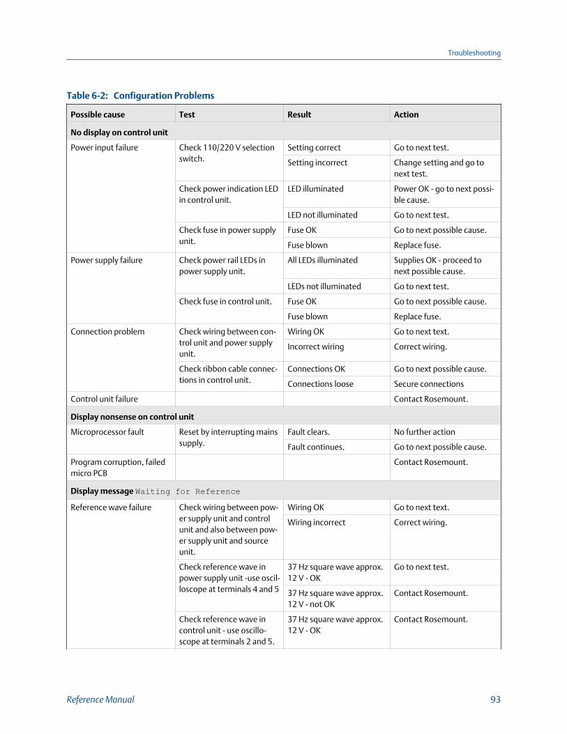
Configuration ProblemsTable 6-2:
Possible cause Test Result Action
No display on control unit
Power input failure Check 110/220 V selectionswitch.
Setting correct Go to next test.
Setting incorrect Change setting and go tonext test.
Check power indication LEDin control unit.
LED illuminated Power OK - go to next possi-ble cause.
LED not illuminated Go to next test.
Check fuse in power supplyunit.
Fuse OK Go to next possible cause.
Fuse blown Replace fuse.
Power supply failure Check power rail LEDs inpower supply unit.
All LEDs illuminated Supplies OK - proceed tonext possible cause.
LEDs not illuminated Go to next test.
Check fuse in control unit. Fuse OK Go to next possible cause.
Fuse blown Replace fuse.
Connection problem Check wiring between con-trol unit and power supplyunit.
Wiring OK Go to next text.
Incorrect wiring Correct wiring.
Check ribbon cable connec-tions in control unit.
Connections OK Go to next possible cause.
Connections loose Secure connections
Control unit failure Contact Rosemount.
Display nonsense on control unit
Microprocessor fault Reset by interrupting mainssupply.
Fault clears. No further action
Fault continues. Go to next possible cause.
Program corruption, failedmicro PCB
Contact Rosemount.
Display message Waiting for ReferenceReference wave failure Check wiring between pow-
er supply unit and controlunit and also between pow-er supply unit and sourceunit.
Wiring OK Go to next text.
Wiring incorrect Correct wiring.
Check reference wave inpower supply unit -use oscil-loscope at terminals 4 and 5
37 Hz square wave approx.12 V - OK
Go to next test.
37 Hz square wave approx.12 V - not OK
Contact Rosemount.
Check reference wave incontrol unit - use oscillo-scope at terminals 2 and 5.
37 Hz square wave approx.12 V - OK
Contact Rosemount.
Troubleshooting
Reference Manual 93

Configuration Problems (continued)Table 6-2:
Possible cause Test Result Action
37 Hz square wave approx.12 V - Not OK
Check and rectify wiring/continuity between powersupply unit and control unit.
Chopper motor failure insource unit
Check if chopper blade is ro-tating.
No Go to next test.
Yes Contact Rosemount.
Replace chopper motor. Fault clears. No further action
Fault continues. Contact Rosemount.
Data Valid LED not illuminated
Analyzer fault condition Interrogate fault status inMode 4.
All Clear Contact Rosemount.
Fault condition identified Go to relevant symptom.
Reference failure
Reference wave failure Proceed as for symptom 3(display message Waitingfor Reference)
Fault clears. No further action
Fault continues. Contact Rosemount.
Low detector level
Incorrect wiring Check wiring. Fault clears. No further action
Fault continues. Go to next possible cause.
Dirty windows or obstructedsight path
Clean and check the Rx andTx windows; clear sight pathbetween receiver unit andsource unit.
Detector levels in range No further action
Fault continues. Go to next possible cause.
Misalignment Realign receiver and sourceunits.
Detector levels in range No further action
Fault continues. Go to next possible cause.
Incorrect gain settings Adjust gains in control unitand/or receiver unit.
Detector levels in range No further action
Fault continues. Go to next possible cause.
Source failure Check heater cartridge. Cartridge open circuit Replace heater cartridge.
Cartridge OK Go to next possible cause.
Source gas cell drive failure Check drive LED in controlunit.
LED flashing Go to next test.
LED not flashing Contact Rosemount.
Check gas cell/filter drive. No movement Contact Rosemount.
Movement Contact Rosemount.
Detector saturated
Incorrect gain settings Adjust gain settings in con-trol unit and/or receiverunit.
Saturation clears. No further action.
Fault continues. Go to next test.
Monitor detector levelsfrom receiver unit.
Signal OK No further action
Signal faulty Contact Rosemount.
Troubleshooting
94 Rosemount CCO 5500

Configuration Problems (continued)Table 6-2:
Possible cause Test Result Action
Modulation frequency out of range
Chopper motor speed out ofrange
Adjust chopper motorspeed.
Modulation frequency inrange
No further action
Unable to adjust Go to next test.
Monitor reference wave-form across test points 10and 11 in power supply unitusing oscilloscope
30 - 45 Hz waveform OK
< 30 or > 45 Hz: waveformincorrect
Contact Rosemount.
Set call out of range
Calibrated with incorrecttarget value or under fluctu-ating gas level
Calibrate with correct targetvalue.
Cal factor in range No further action
Cal factor out of range Go to next possible cause.
Poor alignment / windowcontamination / path ob-scured
Proceed as for low detectorlevel
Cal factor in range No further action
Cal factor out of range Go to next possible cause.
Source unit gas cell drivefailure
Proceed as for low detectorlevel.
Cal factor in range No further action
Cal factor out of range Go to next possible cause.
D2 detector/circuit failure Check D2 signal level. OK Go to next possible cause.
Not OK Go to next test.
Monitor D2 signal from Rx. OK
Not OK Contact Rosemount.
Source gas cell failure Replace source unit gas cell. Cal factor in range No further action
Cal factor out of range Go to the next possiblecause.
Receiver gas cell failure Replace receiver unit gascell.
Cal factor in range No further action
Cal factor out of range Contact Rosemount.
Operational ProblemsTable 6-3:
Possible cause Test Result Action
Output reading permanently zero or full scale
Incorrect normalizing pa-rameter setting
Enter parameter mode andensure all parameters are asrequired.
Parameters correct Go to next possible cause.
Parameters incorrect Enter correct parameters.
Incorrect calibration (Set Calvalue) zero gas level
Enter DIAGNOSTICS modeand observe the Y(60) value.
1800 < Y < 2010 Instrument OK: true level ofgas in duct (output perma-nently zero)
Y <1800 Go to next possible cause.
Troubleshooting
Reference Manual 95

Operational Problems (continued)Table 6-3:
Possible cause Test Result Action
Detector levels low or satu-rated
Enter DIAGNOSTICS modeand check the detector lev-els and saturation count.
Detector levels OK Go to next possible cause.
Detector levels out of toler-ance
Reconfigure the instrumentand consult the fault-findingtable again.
Output circuitry failure Enter SET UP mode (config-ure output and attempt toset zero and span).
Output responds correctly. Reconfigure the instrumentand consult the fault-findingtable again.
Output does not respondcorrectly.
Replace control unit.
Averages not updated
Fault condition exists. Enter DIAGNOSTICS modeand check fault condition.
Fault condition exits. Refer to Section 4.9.5.
No fault condition Go to next possible cause.
Plant status contact in con-trol unit has been made.
Check plant status input LEDin control unit.
LED off Operation correct - stablegas level.
LED on Plant status in use - instru-ment will not update untilplant on.
6.3 Component testsSome instrument components/operation can be verified as follows:
6.3.1 Heater cartridgeComplete the following steps to check the analyzer's heater cartridge.
1. Perform steps 1 through 4 in Section 5.2.1.
2. Remove one lead from the heater cartridge and measure the resistance across thetwo cartridge terminals.
It should be about 3.5 ohms. If the circuit is open, you need to replace the heatercartridge.
6.3.2 Chopper motorComplete the following steps to check the analyzer's chopper motor.
1. Power up the Rosemount™ CCO 5500 Analyzer.
2. Observe the chopper motor and blade between the lens and heater cartridge.
If the blade is spinning, the chopper motor is OK.
Troubleshooting
96 Rosemount CCO 5500

3. If the blade is not spinning, measure the supply to the chopper motor voltage at thetest points M+ and M- on the circuit board (Figure 5-5).
The voltage should read approxmately 1 Vdc. If the voltage is good, replace thechopper motor. If the voltage is not 1 Vdc, the source unit electronics are suspect.
6.4 LED indicationsIf you suspect instrument malfunction, there are LEDs within the instrument indicatingvarious power rails and equipment operations.
LEDs Description
Control unit LEDs
5 V, -15, +15 Situated top/left of processor. Should all be ON,indicating that the power supplies to the instru-ment are functioning correctly.
M-DIR Should operate approximately every 4 seconds.
SOL_MDRV Supply to the solenoid that drives the filter intothe optical path within the receiver pulses everytime the M-DIR changes (approximately every 2seconds).
+V1, -V1, and +12 V Middle bottom left of board. All should be ON.Power supplies to the isolated analog currentoutput.
+12 V Bottom left of board. Should be ON. Indicationof the isolated supply for the plant status input.
PS Bottom left of the board. In normal operation,this LED should be OFF. During plant-off periods,however, if the plant status is being used, thisLED illuminates, and the rolling averages are notupdated.
Receiver LEDs
+V and -V These LEDs should be ON indicating that thepower supplies within the unit are functioningcorrectly.
Source LEDs
+V and -V These LEDs should be ON indicating that thepower supplies within the unit are functioningcorrectly.
Troubleshooting
Reference Manual 97
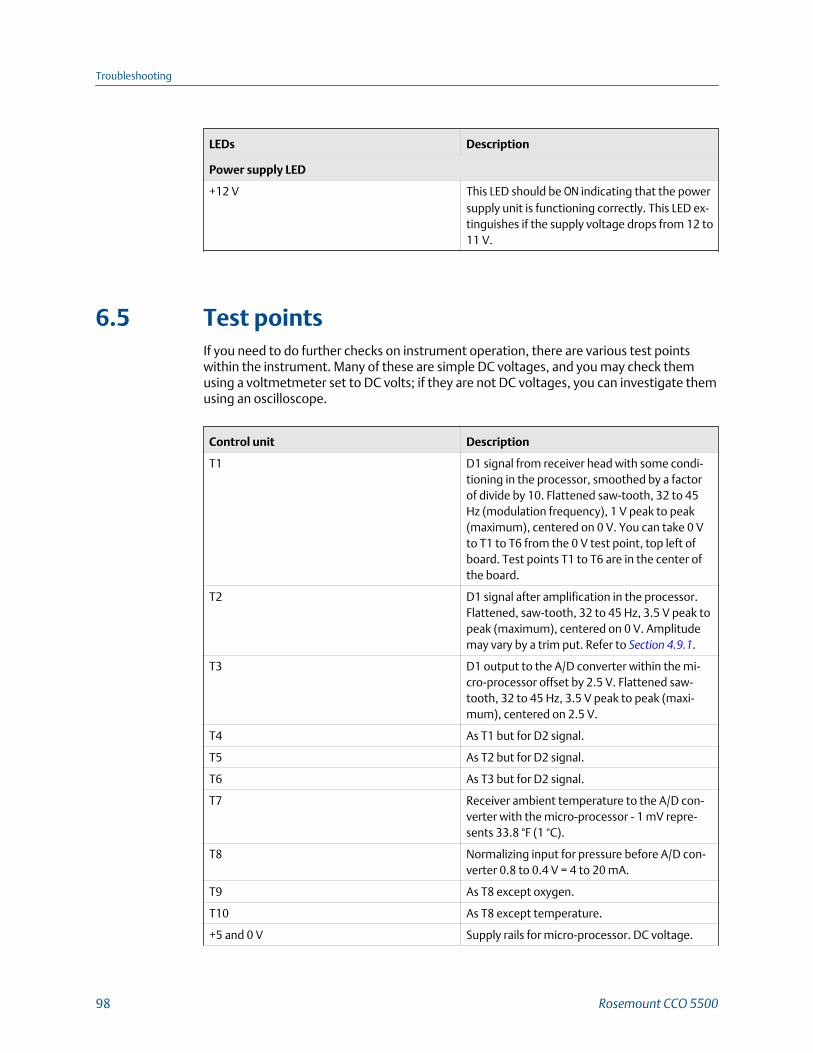
LEDs Description
Power supply LED
+12 V This LED should be ON indicating that the powersupply unit is functioning correctly. This LED ex-tinguishes if the supply voltage drops from 12 to11 V.
6.5 Test pointsIf you need to do further checks on instrument operation, there are various test pointswithin the instrument. Many of these are simple DC voltages, and you may check themusing a voltmetmeter set to DC volts; if they are not DC voltages, you can investigate themusing an oscilloscope.
Control unit Description
T1 D1 signal from receiver head with some condi-tioning in the processor, smoothed by a factorof divide by 10. Flattened saw-tooth, 32 to 45Hz (modulation frequency), 1 V peak to peak(maximum), centered on 0 V. You can take 0 Vto T1 to T6 from the 0 V test point, top left ofboard. Test points T1 to T6 are in the center ofthe board.
T2 D1 signal after amplification in the processor.Flattened, saw-tooth, 32 to 45 Hz, 3.5 V peak topeak (maximum), centered on 0 V. Amplitudemay vary by a trim put. Refer to Section 4.9.1.
T3 D1 output to the A/D converter within the mi-cro-processor offset by 2.5 V. Flattened saw-tooth, 32 to 45 Hz, 3.5 V peak to peak (maxi-mum), centered on 2.5 V.
T4 As T1 but for D2 signal.
T5 As T2 but for D2 signal.
T6 As T3 but for D2 signal.
T7 Receiver ambient temperature to the A/D con-verter with the micro-processor - 1 mV repre-sents 33.8 °F (1 °C).
T8 Normalizing input for pressure before A/D con-verter 0.8 to 0.4 V = 4 to 20 mA.
T9 As T8 except oxygen.
T10 As T8 except temperature.
+5 and 0 V Supply rails for micro-processor. DC voltage.
Troubleshooting
98 Rosemount CCO 5500

12 V Suppy rail for the plant status input.
+15 V, -15 V, and 0 VA Supply rails for the analog current output.
VIN Output from the D/A converter. 0 to 2.5 V repre-sents 0 to 20 mA (4 mA at 0 V).
-15 V1, 0 V, and +15 V1 Isolated supply for the analog current output.
0 VB and +12 VB Isolated supply for the plant status input.
F Reference wave from the source unit (via thepower supply). Square wave, 30 to 45 Hz, 5 Vpeak to peak, centered on 2.5 V.
Power supply Description
0 V and +12 V Power supply for the instrument.
Receiver Description
0 V 0 V for the receiver.
T1 Detector output without conditioning.
T2 Detector output after first stage of gain.
T3 Detector output after both stages of gain.
Source Description
S- 0 V supply to the heater cartridge
S+ 12 V supply to the heater cartridge
M+ and M- Supply to the chopper motor (+1 Vdc).
T3 Reference wave.
T4 Reference wave.
Troubleshooting
Reference Manual 99

Troubleshooting
100 Rosemount CCO 5500

7 Spare parts
Contact Rosemount™ customer service center with the serial number of your instrument,and they will make recommendations based on your system. Below are typical spares thatyou should consider.
Rosemount CCO 5500 Analyzer Recommended Spare PartsTable 7-1:
Part number Description
1A99995H01 Source unit assembly
1A99995H02 Receiver unit assembly
1A99995H03 Power supply assembly
1A99995H04 Control unit assembly
1A99995H05 Purge assembly
1A99995H06 Site mounting flanges (set of 2), 6.5 in. (165mm) OD, 4 M8 holes on 4.9 in. (125 mm) BC
1A99995H07 Heater cartridge
1A99995H08 Protection window
1A99995H09 Gasket, source/receiver to air purge assembly
1A99995H10 Gasket, source/receiver to site flange
1A99995H11 Chopper motor and disk
1A99995H12 Stepper motor and gearbox
1A99995H20 IR detector
1A99995H21 Calibration check cell holder (no cell)
1A99995H22 CO calibration check cell (specify value)
1A99995H23 Span gas cell, 10 mm
1A99995H24 100% gas cell, 5 mm
1A99995H25 Lens
Spare parts
Reference Manual 101

Spare parts
102 Rosemount CCO 5500

Appendix ATheory of operation
A.1 Infrared source unitAt the heart of this unit is a small heater assembly designed to give a high intensityuniform source of infrared energy. The heater assembly can provide in excess of two yearsof continuous operation with a power consumption of only 26 watts. The heater has astainless steel cylindrical core, plasma coated with refractory, and around which is aKanthal heating element. This is then enclosed within refractory fibers and encapsulated inan aluminum cartridge. In the infrequent event of failure, you can easily replace thecomplete heater assembly on site.
A motor-drive disc then chops the radiation emitted by the heater, and a lens focuses theradiation across the duct. A small DC motor drives the chopper disc. A radiation detectormonitors the phase and frequency of the chopper disc to provide a reference signal thatthe control unit uses.
A stepper motor and gear box assembly swing a small calibration cell containing purereference gas (CO) into the sight path to enable continuous calibration updates. Thechopper motor and stepper motor represent the only moving components in the entiresystem.
A printed circuit board mounted at the front of the unit provides control circuitry for theheater, the motors, and the reference ware detector.
Figure A-1 illustrates the operation of the source and receiver units.
Theory of operation
Reference Manual 103
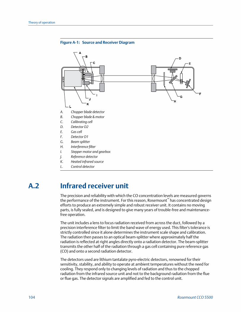
Source and Receiver DiagramFigure A-1:
A. Chopper blade detectorB. Chopper blade & motorC. Calibrating cellD. Detector D2E. Gas cellF. Detector D1G. Beam splitterH. Interference filterI. Stepper motor and gearboxJ. Reference detectorK. Heated infrared sourceL. Control detector
A.2 Infrared receiver unitThe precision and reliability with which the CO concentration levels are measured governsthe performance of the instrument. For this reason, Rosemount™ has concentrated designefforts to produce an extremely simple and robust receiver unit. It contains no movingparts, is fully sealed, and is designed to give many years of trouble-free and maintenance-free operation.
The unit includes a lens to focus radiation received from across the duct, followed by aprecision interference filter to limit the band wave of energy used. This filter's tolerance isstrictly controlled since it alone determines the instrument scale shape and calibration.The radiation then passes to an optical beam-splitter where approximately half theradiation is reflected at right angles directly onto a radiation detector. The beam-splittertransmits the other half of the radiation through a gas cell containing pure reference gas(CO) and onto a second radiation detector.
The detectors used are lithium tantalate pyro-electric detectors, renowned for theirsensitivity, stability, and ability to operate at ambient temperatures without the need forcooling. They respond only to changing levels of radiation and thus to the choppedradiation from the infrared source unit and not to the background radiation from the flueor flue gas. The detector signals are amplified and fed to the control unit.
Theory of operation
104 Rosemount CCO 5500

A.3 Control unitThe control unit is a housed in a fully-sealed cast-aluminum enclosure. It houses themicroprocessor to monitor the data from the receiver and produces a 4-20 mA outputsignal for gas levels within the flue.
A non-volatile RAM section, requiring no battery back-up, enables all of its operation datato be retained during a power down condition. The instrument can resume operationimmediately when power is restored without having to be recalibrated.
Enter all operation data via a surface-mounted keypad. A 32-character LCD provides youwith measurement details and diagnostic information.
If required, inputs are available to receive the 4-20 mA outputs from the normalizingmeasurement transducers (oxygen, temperature, and pressure). You can also enter thisdata via the keypad or via the serial data port.
A serial communication facility within the processor allows the instrument tocommunicate with other Rosemount™ analyzers and a central data logging unit.
A.4 Power supply unitThe power supply unit is housed in a fully-sealed cast aluminum enclosure. A supplyvoltage switch allows you to select from either 110 or 220 V. This provides an extremelystable power source able to cope with large fluctuations in the supply voltage. Also, thedata valid and high gas alarm contact outputs are located in the unit.
A.5 Air purgeThe air purge unit has an integral adjustable mount and provides the interface betweenthe site mounting flange and the source/receiver units. Rosemount™ designed the airpurge to provide a steady laminar flow of air away from the instrument lens to preventoptical contamination.
A supply of air to the purge is essential. See Section 1.4 for details.
A.6 Isolating valvesIf you need to, you may attach isolating valves between the air purge units and the sitemounting flanges. Use the customer supplied isolating valves to provide protection forpersonnel servicing instruments on high pressure ducts.
Theory of operation
Reference Manual 105

A.7 Principles and modes of operation
A.7.1 Calculation of gas concentrationThe analzyer determines gas levels by measuring the absoption of infrared radiationtransmitted through the flue gas. The wave bands from the infrared radiation are sensitiveto absorption by the measurement gas. The Rosemount™ CCO 5500 Analyzer has twodetectors: one measures the radiation directly to provide a live output, sensitive to themeasurement gas. The second detector measures the radiation after passing through agas cell fitted with pure reference gas (CO). This provides a reference measurementcompletely unaffected by the measurement gas.
The basic expression from which the gas concentration in the gas is determined is:
Y = G - K(D2/D1)
Where: D1 = the reference output from the detector
D2 = the live output from the detector
G = a scaling factor (16000)
K = a constant, known as the zero correction factor, set so that when there is zeromeasurement gas in the duct, Y = 0
thereby, K = G(D10/D20)
The analyzer then smooths, linearizes, and compensates the parameter Y for effects ofpath length and flue gas temperature to produce a measurement of CO gas concentrationin the flue gas.
A.7.2 Error compensationThe accurate determination of gas concentration depends on the measurement of theradiation levels received by the detectors. Any error in the measurement caused bydetector drift will produce errors in the calculation of the gas level. In order to maintainaccuracy, it is necessary to compensate for such drifts. The Rosemount™ CCO 5500Analyzer uses a technique of repeated calibration adjustments.
The operating cycle of the instrument is in two parts. First, the instrument obtainsmeasurements from the two detector outputs, D1 and D2. It then positions the calibrationcell containing pure CO in the sight path and measures the two detector outputs again togive readings E1 and E2.
From the basic scale shape equation:
Y = G - K (D1/D2)
and from the calibration equation:
Y0 = G - K (E2/E1)
or K = (G - Y0)(E1/E2)
Theory of operation
106 Rosemount CCO 5500

When substituting trhe value of K into the scale shape equation:
Y = G - (G-Y0)(E1/E2)(D2/D1)
The two ratios E1/D1 and E2/D2, being derived each from one detector, are independentof any detector drift. This makes the instrument output independent of any drift or changein detector gain characteristic.
This operating routine, giving measurements first of D1 and D2 and then, with thecalibration cell in position, of E1 and E2, repeats continuously and provides an effectivecontinuous calibration update to enable accuracy to be maintained at all times.
A.7.3 Calculation sequenceDuring each operating cycle, the instrument performs the calculations given below:
• Measure D1 & D2
• Measure E1 & E2
• Compute Y
• Smooth Y
• Linearize and correct for path length
• Normalize the measurement
• Smooth the result to produce a final %CO output
A.7.4 Normalization equationsNormalization of data collected by the analyzer is essential to compare emission levels ofpollutants into the atmosphere. Software in the Rosemount™ CCO 5500 Analyzer performsall calculations and provides results in various units, vpm, mg/m3, and mg/Nm3. Thefollowing paragraphs describe the derivation of these results.
The Rosemount CCO 5500 Analyzer is a cross-duct type that measures the quantity(number of molecules) of gas within its sight path. It converts this measurement into aconcentration that fully compensates for the expansion effects of temperature, whileassuming constant atmospheric pressure. The basic measurement is referred to as ppm(parts per million). However, to achieve a true concentration vpm (ppm by volume), theppm value must be normalized for pressure using the following expression.
Correction to standard pressure:
where standard pressure is taken as 101 kPa.
Conversion to mass concentration
The next stage in the process is to determine the mass concentration. The conversion atSTP uses conversion factors determined as follows:
Theory of operation
Reference Manual 107

where: N = conversion factor
RMM = Relative molecular mass of the gas
V = 22.4 (the standard volume of ideal gas)
Conversion factors (N)
The conversion factors (N) for the analyzer are as follows:
Relative molecular mass (RMM) = 12 + 16 = 28
1 vpm = 28/22.5 - 1.25 mg/m3
The mass concentration of the gas at STP is calculated as:
mg/m3 @ STP = N (vpm)
This value is the mass concentration of the gas at STP.
Correction for oxygen and water vapor
Finally, you need to consider the effects of water vapor and oxygen. Because theinstrument has already normalized the vpm measurement for temperature and pressure,further normalization is required only for the dilution effects of water vapor and oxygen.These are straightforward calculations:
20.9% is taken as the level of free oxygen in dry air.
When the measured %O2 is a wet measurement, the instrument must correct it to a drymeasurement. When the measured O2 concentration is defined as a wet measurement inthe analyzer software, the software automatically performs this correction using thisequation:
When no correction for a wet measurement is required:
standard %O2 = %O2 measured
When no correction is required for water vapor:
%H2O = 0
After the instrument has performed all calculations, the resulting measurement is theeffective mass concentration (mg/Nm3) of the pollutant normalized to standardconditions.
Theory of operation
108 Rosemount CCO 5500

Measured conditions
Where measured values are required (e.g., to calculate rates of emissions) they need to berecalculated for measured temperature and pressure using the equation:
by substituting the correction for standard pressure:
the measured mass concentration of the CO gas is:
A.7.5 Principles of cross-duct gas analyzersCross-duct analyzers work on the basic principle that infrared (IR) energy is absorbed byparticular gases in a manner very specific to that gas.
Although cross-duct analysis will differ from gas to gas, the basic principles are similar forall measured gases. This section examines the analysis of carbon monoxide in detail.
Carbon monoxide infrared absorption spectrum
Carbon monoxide absorbs infrared energy in a band between wavelengths ofapproximately 4.5 and 4.9 µm. The absorption spectrum is complex and is illustrated in Figure A-2 below.
CO Infrared Absorption SpectrumFigure A-2:
Theory of operation
Reference Manual 109

However, carbon dioxide and water vapor also absorb energy within this wave band.Fortunately, at 4.7 µm, IR absorption by each of these gases is at a minimum. Figure A-3demonstrates how the absorption spectra of CO2, CO, and water vapor affectswavelengths between 4.5 and 4.9 µm.
Absorption spectra of CO, CO2, and water vapor
A narrow band pass filter only passes IR energy at wavelengths around 4.7 µm. By usingthis filter, correctly designed CO analyzers are able to ignore the effects of water vapor andCO2. No other flue gases absorb IR energy in the band. The filter characteristics are shownin Figure A-3.
Comparison of SpectraFigure A-3:
Transmissivity of CO within the 4.7 µm band
The concentration of CO affects the IR energy's transmission through the gas at about 4.7µm. Figure A-4 illustrates how the energy within the selected band varies with COconcentration.
Theory of operation
110 Rosemount CCO 5500

Transmissivity of COFigure A-4:
The characteristics of the 4.7 µm filter fix the shape of this curve, and the shape cannotchange. The curve is practically flat at CO concentrations above 10,000 ppm-meters. Across-duct monitor effectively measures CO molecules in its optical path so the sameconcentration of CO will have a greater effect across a large measurement path than asmall measurement path. The term ppm-meters is the concentration of CO within the ductmultiplied by the gas path length (in meters) over which it has been measured.
Carbon monoxide calculation
The Rosemount CCO 5500 Analyzer takes two measurements of IR energy in the narrowband around 4.7 µm. It takes both measurements after the beam has passed through thegas to be measured. One beam, however, also passes through a cell containing pure CO(the gas cell shown in Figure A-1). The beam absorbs all the energy capable of beingabsorbed by CO and provides a reference that is unaffected by any CO in the duct.However, any other material (e.g., dust) which reduces the energy received from thesource unit will affect the beam.
The second beam does not pass through the cell and is very sensitive to changes in COwithin the duct.
The measurement of CO is calculated from a parameter Y, where:
Y - G-K(D2/D1)
and D2 = the live detector output
D1 = the reference detector output
K = a composite gain factor which takes account of all optical and electronic gains
G = scaling factor
Calibration
Figure A-5 shows the parameter Y plotted for the change in CO concentration.
Theory of operation
Reference Manual 111

Calibration CurveFigure A-5:
This is the calibration curve for the instrument, opposite in shape to the transmissivitycurve shown in Figure A-4. Characteristics of the 4.7 µm filter fix each curve, and the curvescannot change. Rosemount analyzers make full use of this scale shape to provide an easilyattainable calibration point.
It is not necessary to calculate K because we know that when the constant K is correct (Y =0 when the CO level = 0) any drift in the measurement can only be due to a change in someoptical or electronic gain. You can always correctthe drift by setting Y to zero when the COlevel is zero.
In practice, however, it is not always possible to produce a zero CO level. But if we considerthe calibration curve, we can see that:
if Y = 0 when CO = 0
then Y = a when CO = b
We can also see from Figure A-5 that at high CO levels the parameter Y becomescompletely insensitive to changing CO levels in the duct, such that:
Y = a when CO > b
By making Y = a when CO > b and Y = 0 when CO - 0, you can eliminate all errors.
You can introduce a gas cell containing pure carbon monoxide can be introduced into theIR beam at the source. This cell represents a value of 10,000 ppm-meters and provides areference point for the calibration of the instrument. Any further CO in the duct will havenegligible effect on the reference point because the calibration curve is flat at these highconcentrations of CO. Well designed cross-duct analyzers introduce this gas cell every fewseconds to continuously check and (if necessary) modify the zero position.
Theory of operation
112 Rosemount CCO 5500

Appendix BReturn equipment to the factory
If you need the factory to repair defective equipment, proceed as follows:
1. Secure a return authorization number from a Rosemount™ sales office orrepresentative before returning the equipment.
You must return equipment with complete identification in accordance withRosemount instructions or Rosemount will not accept it. In no event, will Emerson™
be responsible for equipment returned without proper authorization andidentification.
2. Carefully pack defective unit in a sturdy box with sufficient shock absorbing materialto ensure that no additional damage will occur during shipping.
3. In a cover letter, describe completely:
a. The symptoms from which you determined that the equipment is faulty.
b. The environment in which the equipment has been operating (housing, weather,vibration, dust, etc.).
c. Site from which equipment was removed.
d. Whether warranty or non-warranty service is requested.
e. Complete shipping instructions for return of equipment.
f. Reference the return authorization number.
4. Enclose a cover letter and purchase order and ship the defective equipmentaccording to instructions provided in Rosemount Return Authorization, prepaid to:
Rosemount, Inc.PAD Repair CenterC/O Rosemount Analytical, Inc.10241 West Little York, Ste 200Houston, Texas 77040Attn: Christi Kluna
If you request warranty service, Rosemount will carefully inspect and test the equipment atthe factory. If failure was due to conditions listed in the standard Rosemount warranty,Rosemount wil repair or replace the equipment at its option and will return an operatingunit to the customer in accordance with the shipping instructions furnished in the coverletter.
For equipment no longer under warranty, Rosemount will repair the equipment at thefactory and return it as directed by the purchase order and shipping instructions.
Return equipment to the factory
Reference Manual 113

Return equipment to the factory
114 Rosemount CCO 5500

Return equipment to the factory
Reference Manual 115

00809-0100-4550
Rev AA
2018
GLOBAL HEADQUARTERSEmerson Automation Solutions6021 Innovation BlvdShakopee, MN 55379, USA
+1 800 999 9307 or +1 952 906 8888
+1 952 949 7001
[email protected] AMERICARosemount8200 Market BoulevardChanhassen, MN 55317
+1 800 999 9307
+1 952 949 7001
EUROPEEmerson Automation SolutionsNeuhofstrasse 19a P.O. Box 1046CH-6340 BaarSwitzerland
+ 41 (0) 41 768 6111
+ 41 (0) 41 768 6300
MIDDLE EAST AND AFRICAEmerson Automation SolutionsEmerson FZEJebel Ali Free ZoneDubai, United Arab Emirates, P.O. Box 17033
+971 4 811 8100
+971 4 886 5465
ASIA-PACIFICEmerson Automation Solutions1 Pandan CrescentSingapore 128461Singapore
+65 777 8211
+65 777 0947
Linkedin.com/company/Emerson-Automation-Solutions
twitter.com/rosemount_news
Facebook.com/Rosemount
youtube.com/RosemountMeasurement
google.com/+RosemountMeasurement
AnalyticExpert.com
©2018 Emerson. All rights reserved.
The Emerson logo is a trademark and service mark of Emerson Electric Co. Rosemount is amark of one of the Emerson family of companies. All other marks are the property of theirrespective owners.