june 1995 ln-25 portable cv/cc semiautomatic wire …
TRANSCRIPT

LN-25 PORTABLE CV/CCSEMIAUTOMATIC WIRE FEEDER
SERVICE MANUAL
Sales and Service through Subsidiaries and Distributors Worldwide
22801 St. Clair Ave. Cleveland, Ohio 44117-1199 U.S.A. Tel. (216) 481-8100
World's Leader in Welding and Cutting Products Premier Manufacturer of Industrial Motors
SVM114-AJune 1995
Safety Depends on YouLincoln arc welding and cuttingequipment is designed and builtwith safety in mind. However,your overall safety can beincreased by proper installation... and thoughtful operation onyour part. DO NOT INSTALL,OPERATE OR REPAIR THISEQUIPMENT WITHOUT READ-ING THIS MANUAL AND THESAFETY PRECAUTIONS CON-TAINED THROUGHOUT. And,most importantly, think before youact and be careful.
For use with machines having Code Numbers: 9218921992209383981098119812101481014910150

SAFETY ii
LN-25
PROTECT YOURSELF AND OTHERS FROM POSSIBLE SERIOUS INJURY OR DEATH. KEEP CHILDRENAWAY. PACEMAKER WEARERS SHOULD CONSULT WITH THEIR DOCTOR BEFORE OPERATING.
Read and understand the following safety highlights. For additional safety information, it is strongly recommended that youpurchase a copy of “Safety in Welding & Cutting - ANSI Standard Z49.1” from the American Welding Society, P.O. Box 351040,Miami, Florida 33135 or CSA Standard W117.2-1974. A Free copy of “Arc Welding Safety” booklet E205 is available from theLincoln Electric Company, 22801 St. Clair Avenue, Cleveland, Ohio 44117-1199.
BE SURE THAT ALL INSTALLATION, OPERATION, MAINTENANCE AND REPAIR PROCEDURES ARE PER-FORMED ONLY BY QUALIFIED INDIVIDUALS.
ARC RAYS can burn.2.a. Use a shield with the proper filter and cover
plates to protect your eyes from sparks andthe rays of the arc when welding or observingopen arc welding. Headshield and filter lensshould conform to ANSI Z87. I standards.
2.b. Use suitable clothing made from durable flame-resistantmaterial to protect your skin and that of your helpers fromthe arc rays.
2.c. Protect other nearby personnel with suitable, non-flammablescreening and/or warn them not to watch the arc nor exposethemselves to the arc rays or to hot spatter or metal.
ELECTRIC SHOCK can kill.1.a. The electrode and work (or ground) circuits
are electrically “hot” when the welder is on.Do not touch these “hot” parts with your bareskin or wet clothing. Wear dry, hole-freegloves to insulate hands.
1.b. Insulate yourself from work and ground using dry insulation.Make certain the insulation is large enough to cover your fullarea of physical contact with work and ground.
In addition to the normal safety precautions, if weldingmust be performed under electrically hazardousconditions (in damp locations or while wearing wetclothing; on metal structures such as floors, gratings orscaffolds; when in cramped positions such as sitting,kneeling or Iying, if there is a high risk of unavoidable oraccidental contact with the workpiece or ground) usethe following equipment:
• Semiautomatic DC Constant Voltage (Wire) Welder.• DC Manual (Stick) Welder.• AC Welder with Reduced Voltage Control.
1.c. In semiautomatic or automatic wire welding, the electrode,electrode reel, welding head, nozzle or semiautomaticwelding gun are also electrically “hot”.
1.d. Always be sure the work cable makes a good electricalconnection with the metal being welded. The connectionshould be as close as possible to the area being welded.
1.e. Ground the work or metal to be welded to a good electrical(earth) ground.
1.f. Maintain the electrode holder, work clamp, welding cable andwelding machine in good, safe operating condition. Replacedamaged insulation.
1.g. Never dip the electrode in water for cooling.
1.h. Never simultaneously touch electrically “hot” parts ofelectrode holders connected to two welders because voltagebetween the two can be the total of the open circuit voltageof both welders.
1.i. When working above floor level, use a safety belt to protectyourself from a fall should you get a shock.
1.j. Also see Items 4.c. and 6.
WARNING ARC WELDING can be hazardous.
FUMES AND GASEScan be dangerous.3.a. Welding may produce fumes and gases
hazardous to health. Avoid breathing thesefumes and gases. When welding, keepyour head out of the fume. Use enoughventilation and/or exhaust at the arc to keep
fumes and gases away from the breathing zone. Whenwelding with electrodes which require specialventilation such as stainless or hard facing (seeinstructions on container or MSDS) or on lead orcadmium plated steel and other metals or coatingswhich produce highly toxic fumes, keep exposure aslow as possible and below Threshold Limit Values (TLV)using local exhaust or mechanical ventilation. Inconfined spaces or in some circumstances, outdoors, arespirator may be required. Additional precautions arealso required when welding on galvanized steel.
3.b. Do not weld in locations near chlorinated hydrocarbon vaporscoming from degreasing, cleaning or sprayingoperations.The heat and rays of the arc can react with sol-vent vapors to form phosgene, a highly toxic gas, and otherirritating products.
3.c. Shielding gases used for arc welding can displace air andcause injury or death. Always use enough ventilation,especially in confined areas, to ensure breathing air is safe.
3.d. Read and understand the manufacturer’s instructions for thisequipment and the consumables to be used, including thematerial safety data sheet (MSDS) and follow youremployer’s safety practices. MSDS forms are available fromyour welding distributor or from the manufacturer.
3.e. Also see item 7b. Apr. ‘93

SAFETY iiii
LN-25
FOR ELECTRICALLYpowered equipment.
6.a. Turn off input power using the disconnectswitch at the fuse box before working onthe equipment.
6.b. Install equipment in accordance with the U.S. NationalElectrical Code, all local codes and the manufacturer’srecommendations.
6.c. Ground the equipment in accordance with the U.S. NationalElectrical Code and the manufacturer’s recommendations.
CYLINDER may explodeif damaged.5.a. Use only compressed gas cylinders
containing the correct shielding gas for theprocess used and properly operatingregulators designed for the gas and
pressure used. All hoses, fittings, etc. should be suitable forthe application and maintained in good condition.
5.b. Always keep cylinders in an upright position securelychained to an undercarriage or fixed support.
5.c. Cylinders should be located:• Away from areas where they may be struck or subjected tophysical damage.
• A safe distance from arc welding or cutting operations andany other source of heat, sparks, or flame.
5.d. Never allow the electrode, electrode holder or any otherelectrically “hot” parts to touch a cylinder.
5.e. Keep your head and face away from the cylinder valve outletwhen opening the cylinder valve.
5.f. Valve protection caps should always be in place and handtight except when the cylinder is in use or connected foruse.
5.g. Read and follow the instructions on compressed gascylinders, associated equipment, and CGA publication P-l,“Precautions for Safe Handling of Compressed Gases inCylinders,” available from the Compressed Gas Association1235 Jefferson Davis Highway, Arlington, VA 22202.
Mar. ‘93
WELDING SPARKS cancause fire or explosion.4.a. Remove fire hazards from the welding area.
If this is not possible, cover them to preventthe welding sparks from starting a fire.Remember that welding sparks and hot
materials from welding can easily go through small cracksand openings to adjacent areas. Avoid welding nearhydraulic lines. Have a fire extinguisher readily available.
4.b. Where compressed gases are to be used at the job site,special precautions should be used to prevent hazardoussituations. Refer to “Safety in Welding and Cutting” (ANSIStandard Z49.1) and the operating information for theequipment being used.
4.c. When not welding, make certain no part of the electrodecircuit is touching the work or ground. Accidental contact cancause overheating and create a fire hazard.
4.d. Do not heat, cut or weld tanks, drums or containers until theproper steps have been taken to ensure that such procedureswill not cause flammable or toxic vapors from substancesinside. They can cause an explosion even though they havebeen “cleaned”. For information, purchase “RecommendedSafe Practices for the Preparation for Welding and Cutting ofContainers and Piping That Have Held HazardousSubstances”, AWS F4.1 from the American Welding Society(see address above).
4.e. Vent hollow castings or containers before heating, cutting orwelding. They may explode.
4.f. Sparks and spatter are thrown from the welding arc. Wear oilfree protective garments such as leather gloves, heavy shirt,cuffless trousers, high shoes and a cap over your hair. Wearear plugs when welding out of position or in confined places.Always wear safety glasses with side shields when in awelding area.
4.g. Connect the work cable to the work as close to the weldingarea as practical. Work cables connected to the buildingframework or other locations away from the welding areaincrease the possibility of the welding current passingthrough lifting chains, crane cables or other alternate circuits.This can create fire hazards or overheat lifting chains orcables until they fail.
4.h. Also see item 7c.

SAFETY iiiiii
LN-25
Mar. ‘93
ELECTRIC AND MAG-NETIC FIELDSmay be dangerous
8.a. Electric current flowing through any conductor causes localized Electric and Magnetic Fields (EMF). Welding current creates EMF fields around welding cables and welding machines
8.b. EMF fields may interfere with some pacemakers, andwelders having a pacemaker should consult their physicianbefore welding.
8.c. Exposure to EMF fields in welding may have other healtheffects which are now not known.
8d. All welders should use the following procedures in order tominimize exposure to EMF fields from the welding circuit:
8.d.1. Route the electrode and work cables together - Securethem with tape when possible.
8.d.2. Never coil the electrode lead around your body.
8.d.3. Do not place your body between the electrode andwork cables. If the electrode cable is on your right side, the work cable should also be on your right side.
8.d.4. Connect the work cable to the workpiece as close aspossible to the area being welded.
8.d.5. Do not work next to welding power source.
FOR ENGINEpowered equipment.
7.a. Turn the engine off before troubleshooting and maintenancework unless the maintenance work requires it to be running.
____________________________________________________
7.b. Operate engines in open, well-ventilatedareas or vent the engine exhaust fumesoutdoors.
____________________________________________________
7.c. Do not add the fuel near an open flamewelding arc or when the engine is run-ning. Stop the engine and allow it to coolbefore refueling to prevent spilled fuelfrom vaporizing on contact with hotengine parts and igniting. Do not spillfuel when filling tank. If fuel is spilled,wipe it up and do not start engine untilfumes have been eliminated.
____________________________________________________
7.d. Keep all equipment safety guards, coversand devices in position and in good repair.Keep hands, hair, clothing and tools awayfrom V-belts, gears, fans and all othermoving parts when starting, operating orrepairing equipment.
____________________________________________________
7.e. In some cases it may be necessary to remove safetyguards to perform required maintenance. Removeguards only when necessary and replace them when themaintenance requiring their removal is complete.Always use the greatest care when working near movingparts.
7.f. Do not put your hands near the engine fan. Do notattempt to override the governor or idler by pushing onthe throttle control rods while the engine is running.
7.g. To prevent accidentally starting gasoline engines whileturning the engine or welding generator during maintenancework, disconnect the spark plug wires, distributor cap ormagneto wire as appropriate.
___________________________________________________

SAFETY iviv
LN-25
PRÉCAUTIONS DE SÛRETÉPour votre propre protection lire et observer toutes les instructionset les précautions de sûreté specifiques qui parraissent dans cemanuel aussi bien que les précautions de sûreté générales suiv-antes:
Sûreté Pour Soudage A L’Arc1. Protegez-vous contre la secousse électrique:
a. Les circuits à l’électrode et à la piéce sont sous tensionquand la machine à souder est en marche. Eviter toujourstout contact entre les parties sous tension et la peau nueou les vétements mouillés. Porter des gants secs et sanstrous pour isoler les mains.
b. Faire trés attention de bien s’isoler de la masse quand onsoude dans des endroits humides, ou sur un plancher met-allique ou des grilles metalliques, principalement dans les positions assis ou couché pour lesquelles une grandepartie du corps peut être en contact avec la masse.
c. Maintenir le porte-électrode, la pince de masse, le câble desoudage et la machine à souder en bon et sûr état defonc-tionnement.
d.Ne jamais plonger le porte-électrode dans l’eau pour lerefroidir.
e. Ne jamais toucher simultanément les parties sous tensiondes porte-électrodes connectés à deux machines à soud-er parce que la tension entre les deux pinces peut être letotal de la tension à vide des deux machines.
f. Si on utilise la machine à souder comme une source decourant pour soudage semi-automatique, ces precautionspour le porte-électrode s’applicuent aussi au pistolet desoudage.
2. Dans le cas de travail au dessus du niveau du sol, se protégercontre les chutes dans le cas ou on recoit un choc. Ne jamaisenrouler le câble-électrode autour de n’importe quelle partiedu corps.
3. Un coup d’arc peut être plus sévère qu’un coup de soliel,donc:
a. Utiliser un bon masque avec un verre filtrant appropriéainsi qu’un verre blanc afin de se protéger les yeux du ray-onnement de l’arc et des projections quand on soude ouquand on regarde l’arc.
b. Porter des vêtements convenables afin de protéger lapeau de soudeur et des aides contre le rayonnement del‘arc.
c. Protéger l’autre personnel travaillant à proximité ausoudage à l’aide d’écrans appropriés et non-inflammables.
4. Des gouttes de laitier en fusion sont émises de l’arc desoudage. Se protéger avec des vêtements de protection libresde l’huile, tels que les gants en cuir, chemise épaisse, pan-talons sans revers, et chaussures montantes.
5. Toujours porter des lunettes de sécurité dans la zone desoudage. Utiliser des lunettes avec écrans lateraux dans leszones où l’on pique le laitier.
6. Eloigner les matériaux inflammables ou les recouvrir afin deprévenir tout risque d’incendie dû aux étincelles.
7. Quand on ne soude pas, poser la pince à une endroit isolé dela masse. Un court-circuit accidental peut provoquer unéchauffement et un risque d’incendie.
8. S’assurer que la masse est connectée le plus prés possible dela zone de travail qu’il est pratique de le faire. Si on place lamasse sur la charpente de la construction ou d’autres endroitséloignés de la zone de travail, on augmente le risque de voirpasser le courant de soudage par les chaines de levage,câbles de grue, ou autres circuits. Cela peut provoquer desrisques d’incendie ou d’echauffement des chaines et descâbles jusqu’à ce qu’ils se rompent.
9. Assurer une ventilation suffisante dans la zone de soudage.Ceci est particuliérement important pour le soudage de tôlesgalvanisées plombées, ou cadmiées ou tout autre métal quiproduit des fumeés toxiques.
10. Ne pas souder en présence de vapeurs de chlore provenantd’opérations de dégraissage, nettoyage ou pistolage. Lachaleur ou les rayons de l’arc peuvent réagir avec les vapeursdu solvant pour produire du phosgéne (gas fortement toxique)ou autres produits irritants.
11. Pour obtenir de plus amples renseignements sur la sûreté, voirle code “Code for safety in welding and cutting” CSA StandardW 117.2-1974.
PRÉCAUTIONS DE SÛRETÉ POURLES MACHINES À SOUDER ÀTRANSFORMATEUR ET ÀREDRESSEUR
1. Relier à la terre le chassis du poste conformement au code del’électricité et aux recommendations du fabricant. Le dispositifde montage ou la piece à souder doit être branché à unebonne mise à la terre.
2. Autant que possible, I’installation et l’entretien du poste seronteffectués par un électricien qualifié.
3. Avant de faires des travaux à l’interieur de poste, la debranch-er à l’interrupteur à la boite de fusibles.
4. Garder tous les couvercles et dispositifs de sûreté à leurplace.

vv
LN-25
MASTER TABLE OF CONTENTS FOR ALL SECTIONS
Page
Safety . . . . . . . . . . . . . . . . . . . . . . . . . . . . . . . . . . . . . . . . . . . . . . . . . . . . i-iv
Installation . . . . . . . . . . . . . . . . . . . . . . . . . . . . . . . . . . . . . . . . . . . . . . . . Section ATechnical Specifications . . . . . . . . . . . . . . . . . . . . . . . . . . . . . . . . . . . . A-2Safety Precautions . . . . . . . . . . . . . . . . . . . . . . . . . . . . . . . . . . . . . . . . A-3Power Source Connection . . . . . . . . . . . . . . . . . . . . . . . . . . . . . . . . . . A-3Gun Cable Connection to Feeder . . . . . . . . . . . . . . . . . . . . . . . . . . . . . A-4Weld Cable Connection . . . . . . . . . . . . . . . . . . . . . . . . . . . . . . . . . . . . A-5Wire Feed Drive Roll and Guide Tube Kits . . . . . . . . . . . . . . . . . . . . . . A-5
Operation . . . . . . . . . . . . . . . . . . . . . . . . . . . . . . . . . . . . . . . . . . . . . . . . . Section BSafety Precautions . . . . . . . . . . . . . . . . . . . . . . . . . . . . . . . . . . . . . . . . B-2General Description . . . . . . . . . . . . . . . . . . . . . . . . . . . . . . . . . . . . . . . B-2Recommended Processes and Equipment . . . . . . . . . . . . . . . . . . . . . . B-2Welding Capability . . . . . . . . . . . . . . . . . . . . . . . . . . . . . . . . . . . . . . . . B-2LN-25 Instruments and Controls . . . . . . . . . . . . . . . . . . . . . . . . . . . . . . B-3Sequence of Operation . . . . . . . . . . . . . . . . . . . . . . . . . . . . . . . . . . . . . B-5Welding . . . . . . . . . . . . . . . . . . . . . . . . . . . . . . . . . . . . . . . . . . . . . . . . B-9Procedure at End of Coil . . . . . . . . . . . . . . . . . . . . . . . . . . . . . . . . . . . B-9Open Arc Welding with a Constant Current Power Source . . . . . . . . . . B-9Automatic Protection Shutdown . . . . . . . . . . . . . . . . . . . . . . . . . . . . . . B-10
Accessories . . . . . . . . . . . . . . . . . . . . . . . . . . . . . . . . . . . . . . . . . . . . . . . Section CLN-25 Option Chart . . . . . . . . . . . . . . . . . . . . . . . . . . . . . . . . . . . . . . . C-2Optional Accessories . . . . . . . . . . . . . . . . . . . . . . . . . . . . . . . . . . . . . . C-3Remote Output Control Options and Control Cable Assemblies . . . . . . C-4
Maintenance . . . . . . . . . . . . . . . . . . . . . . . . . . . . . . . . . . . . . . . . . . . . . . . Section DSafety Precautions . . . . . . . . . . . . . . . . . . . . . . . . . . . . . . . . . . . . . . . . D-2Routine Maintenance . . . . . . . . . . . . . . . . . . . . . . . . . . . . . . . . . . . . . . D-2Circuit Protection and Automatic Shutdown . . . . . . . . . . . . . . . . . . . . . . D-2Adjusting Speed Sensor Module . . . . . . . . . . . . . . . . . . . . . . . . . . . . . . D-2Calibration of LN-25 Wire Speed Dial . . . . . . . . . . . . . . . . . . . . . . . . . . D-3
Theory of Operation . . . . . . . . . . . . . . . . . . . . . . . . . . . . . . . . . . . . . . . . . Section EGeneral Description . . . . . . . . . . . . . . . . . . . . . . . . . . . . . . . . . . . . . . . E-2Control Circuit Operation . . . . . . . . . . . . . . . . . . . . . . . . . . . . . . . . . . . E-2Auxiliary Circuits . . . . . . . . . . . . . . . . . . . . . . . . . . . . . . . . . . . . . . . . . . E-4
Troubleshooting and Repair . . . . . . . . . . . . . . . . . . . . . . . . . . . . . . . . . . Section FHow to Use Troubleshooting Guide . . . . . . . . . . . . . . . . . . . . . . . . . . . F-2PC Board Troubleshooting Procedures . . . . . . . . . . . . . . . . . . . . . . . . . F-3Troubleshooting Guide . . . . . . . . . . . . . . . . . . . . . . . . . . . . . . . . . . . . . F-4Test Procedures . . . . . . . . . . . . . . . . . . . . . . . . . . . . . . . . . . . . . . . . . . F-7Component Replacement Procedures . . . . . . . . . . . . . . . . . . . . . . . . . F-20Retest After Repair . . . . . . . . . . . . . . . . . . . . . . . . . . . . . . . . . . . . . . . . F-38
Electrical Diagrams . . . . . . . . . . . . . . . . . . . . . . . . . . . . . . . . . . . . . . . . . Section GWiring Diagrams . . . . . . . . . . . . . . . . . . . . . . . . . . . . . . . . . . . . . . . . . . G-3Operating Schematics . . . . . . . . . . . . . . . . . . . . . . . . . . . . . . . . . . . . . G-5Control PC Board Layout . . . . . . . . . . . . . . . . . . . . . . . . . . . . . . . . . . . G-7Contactor PC Board Layout . . . . . . . . . . . . . . . . . . . . . . . . . . . . . . . . . G-11
Parts Manual . . . . . . . . . . . . . . . . . . . . . . . . . . . . . . . . . . . . . . . . . . . . . . . P-175

NOTES vi
TABLE OF CONTENTS- INSTALLATION SECTION -
LN-25
Installation . . . . . . . . . . . . . . . . . . . . . . . . . . . . . . . . . . . . . . . . . . . . . . . . Section ATechnical Specifications . . . . . . . . . . . . . . . . . . . . . . . . . . . . . . . . . . . . A-2Safety Precautions . . . . . . . . . . . . . . . . . . . . . . . . . . . . . . . . . . . . . . . . A-3Power Source Connection . . . . . . . . . . . . . . . . . . . . . . . . . . . . . . . . . . A-3
DC-250 . . . . . . . . . . . . . . . . . . . . . . . . . . . . . . . . . . . . . . . . . . . . . A-3DC-400 and CV-400 . . . . . . . . . . . . . . . . . . . . . . . . . . . . . . . . . . . A-3DC-600 . . . . . . . . . . . . . . . . . . . . . . . . . . . . . . . . . . . . . . . . . . . . . A-4R3S-325 . . . . . . . . . . . . . . . . . . . . . . . . . . . . . . . . . . . . . . . . . . . . A-4SAM-400, -650 . . . . . . . . . . . . . . . . . . . . . . . . . . . . . . . . . . . . . . . A-4SA-200, -250 or SAE-300, -400 . . . . . . . . . . . . . . . . . . . . . . . . . . . A-4Invertec, CV300 and other newer Lincoln Power Sources . . . . . . . . A-4
Gun Cable Connection to Feeder . . . . . . . . . . . . . . . . . . . . . . . . . . . . . A-4Weld Cable Connection . . . . . . . . . . . . . . . . . . . . . . . . . . . . . . . . . . . . A-5
Electrode Cable Connection . . . . . . . . . . . . . . . . . . . . . . . . . . . . . . A-5Work Cable Connection . . . . . . . . . . . . . . . . . . . . . . . . . . . . . . . . . A-5
Wire Feed Drive Roll and Guide Tube Kits . . . . . . . . . . . . . . . . . . . . . . A-5
Section A

INSTALLATION A-2
LN-25
A-2
VOLTAGE
Modes Range
Constant Voltage (CV)or 15-40 VDC (110VDC Maximum OCV)
Constant Current (CC)
RATED CURRENT
Without Contactor With Contactor
500 Amps 60% Duty Cycle 300 Amps 60% Duty Cycle
WIRE SPEED RANGE
50 – 700 Inches Per Minute (IPM)
RECOMMENDED ELECTRODE WIRE SIZES
Diameter Wire Type
.023" to 1⁄16" SOLID STEEL WIRE
.035" to 5⁄64" CORED WIRE
.035" to 1⁄16" ALUMINUM WIRE
PHYSICAL DIMENSIONS
HEIGHT WIDTH DEPTH WEIGHT
(Handle Down) w/o Options
14 Inches 7.4 Inches 21 Inches 28 lbs(354 mm) (187 mm) (531 mm) (13 kg)
RATED CURRENT
WIRE FEED SPEED
PHYSICAL DIMENSIONS
WIRE DIAMETERS
VOLTAGE
TECHNICAL SPECIFICATIONS – LN-25

INSTALLATION A-3
LN-25
A-3
ELECTRIC SHOCK can kill.
• Do not operate with coversremoved.
• Turn off power source beforeinstalling or servicing.
• Do not touch electricallyhot parts.
• Turn the input power to thewelding power source off at thefuse box before working in theterminal strip.
• Only qualified personnel shouldinstall, use or service thisequipment.
DC-250
a. Connect a jumper from 2 to 4 on the power sourceterminal strip so the output will be energized whenthe DC-250 is turned on.
b. Connect electrode cable to the “Innershield/GMAW” output terminal of polarity required byelectrode. Connect work lead to other“Innershield/GMAW” output terminal.
c. Place “Set to CV Electrode Cable Polarity” switchat appropriate position.
d. Place power source toggle switch in “OutputControl at DC-250” position, unless a RemoteControl is connected to 75, 76 and 77 on the DC-250 terminal strip.
e. Place mode switch in “Innershield GMAW (CV)”position. Set CV arc control to “2” (or “NORMAL”on some machines). Init ial ly set the outputcontrol on “7”.
DC-400 AND CV-400
a. Connect a jumper from 2 to 4 on the powersource terminal strip so the output wil l beenergized when the power source is turned on.
NOTE: DC-400 machines above Code 9200 havean output toggle switch to perform this function.
b. Connect the electrode cable to the outputterminal of polarity required by electrode.Connect work lead to other output terminal.
SAFETY PRECAUTIONS
Unless an optional output control or contactor is usedwith the LN-25, the electrode circuit (including weldingwire, wire drive and welding gun) is electrically hotwhen the welding power source is on. The gun triggercontrols wire feed only.
Disconnect or shut off welding power source beforemaking connections or installations to the LN-25.
Welding gun should be stored in the insulatedgun holder, located near the rear on the top of theLN-25 case, to avoid accidental arcing.
ELECTRIC SHOCK can kill.
• Do not touch metal portionsof the LN-25 lead clip whenwelding power source is on.
POWER SOURCE CONNECTION
The LN-25 can be used with any DC welding powersource. A constant voltage power source isrecommended; however, the LN-25 can also be usedwith a constant current power source as long as theopen circuit voltage is less than 110V DC.
Do not use LN-25 models below Code 9200 with anyTIG or Square Wave welding power sources. Do notuse LN-25 models equipped with internal contactorswith non- Lincoln TIG or Square Wave welding powersources. Damage to the LN-25 circuit can occur as aresult of the high output inductance typicallyassociated with these power sources. TIG highfrequency power should never be applied to the LN-25.
If not using an LN-25 Remote Output Control option(See Remote Output Control Options and CableAssemblies Section), the power source output mustbe electrically “hot” at all times when the powersource is turned on.
See the power source instruction manual for properpower source connections and setting required.
WARNING
WARNINGWARNING
CAUTION


INSTALLATION A-5
LN-25
A-5
Install the barbed fitting and union nut to the 5⁄8-18female inert gas fitting on the front panel of the LN-25 case. Connect the 3⁄16" I.D. gas hose from the guncable to the barbed fitting.
When the gun is to be removed, this fitting can beeasily detached by loosening the union nut.
WELD CABLE CONNECTION
The size of the electrode cable and work cable mustbe sufficient for the maximum weld current and totalcable length to be used. Refer to table A.1.
TABLE A.1
Total Cable LengthWeld Current
60% Duty Cycle 50'-100' 100'-150' 150'-200' 200'-250'
200Amps 2 AWG 2 AWG 1 AWG 1/0300Amps 1 AWG 1 AWG 1/0 2/0400Amps 2/0 2/0 3/0 3/0500Amps 2/0 3/0 3/0 4/0
ELECTRODE CABLE CONNECTION
On units without an internal contactor route theelectrode cable through the oval hole in the LN-25 rearpanel, then along the case floor behind the reelsupport and around the door side of the wire drive.Connect the electrode cable to the LN-25 using the1⁄2" bolt on the front of the wire drive.
On units with an internal contactor connect theelectrode cable to the LN-25 electrode input cable withthe nut and bolt provided. Tape the bolted connection.
WORK CABLE CONNECTION
Connect a work lead of sufficient size between theproper output stud on the power source and thework. Be sure the connection to the work makest ight meta l - to-meta l e lect r ica l contact . Poorwork lead connections can result in poor weldingperformance.
WIRE FEED DRIVE ROLL ANDGUIDE TUBE KITS
Turn off power source before installing or changingdrive roll and/or guide tubes.
NOTE: The maximum wire sizes the LN-25 willsatisfactorily feed are 5⁄64" cored and 1⁄16" solidelectrodes.
The electrode sizes that can be fed with each roll andguide tube are stencilled(1) on each part. Check the kitfor proper components. See the instructions, includedwith the drive roll kit, to install these parts on newmachines or replace them on used machines. Referto table A.2.
TABLE A.2
Kit Instructions
Steel Wire Sizes:.068-5⁄64 Cored KP450-3⁄32 S179841⁄16 (.062) Cored or Solid -1⁄16
Steel(Can also be used for .052).045 and .052 Solid Steel -.052.045 and .052 Cored -.052C.023-.035 Solid Steel KP451-.035S S17831
Aluminum Wire Sizes:1⁄16 KP452-1⁄16A S170833⁄64 -3⁄64A.035 -.035A
(1)Drive rolls for .045-.052 cored electrode sizes are stencilled witha “C” suffix to the wire sizes. Drive rolls for aluminum wire sizesare stencilled with an “A” suffix to the wire sizes.
WARNING

NOTES A-6A-6
LN-25

TABLE OF CONTENTS- OPERATION SECTION -
LN-25
Operation . . . . . . . . . . . . . . . . . . . . . . . . . . . . . . . . . . . . . . . . . . . . . . . . Section BSafety Precautions . . . . . . . . . . . . . . . . . . . . . . . . . . . . . . . . . . . . . . . . B-2General Description . . . . . . . . . . . . . . . . . . . . . . . . . . . . . . . . . . . . . . . B-2Recommended Processes and Equipment . . . . . . . . . . . . . . . . . . . . . . B-2Welding Capability . . . . . . . . . . . . . . . . . . . . . . . . . . . . . . . . . . . . . . . . B-2LN-25 Instruments and Controls . . . . . . . . . . . . . . . . . . . . . . . . . . . . . . B-3Sequence of Operation . . . . . . . . . . . . . . . . . . . . . . . . . . . . . . . . . . . . . B-5
Loading Electrode . . . . . . . . . . . . . . . . . . . . . . . . . . . . . . . . . . . . . B-5Mounting 22 to 30 lb Readi-Reel Coils . . . . . . . . . . . . . . . . . . . B-5Mounting 10 to 30 lb Spools . . . . . . . . . . . . . . . . . . . . . . . . . . . B-5Mounting 13 or 14 lb Innershield Coils . . . . . . . . . . . . . . . . . . . B-5
Loading Wire Drive . . . . . . . . . . . . . . . . . . . . . . . . . . . . . . . . . . . . B-6Idle Roll Pressure Setting . . . . . . . . . . . . . . . . . . . . . . . . . . . . . . . . B-6Presetting Wire Feed Speed . . . . . . . . . . . . . . . . . . . . . . . . . . . . . B-7
Setting Constant Wire Feed Speed (CV Mode) . . . . . . . . . . . . . B-7Setting Arc Sensing Wire Feed Speed (VV [CC] Mode) . . . . . . B-7
Making a Weld . . . . . . . . . . . . . . . . . . . . . . . . . . . . . . . . . . . . . . . . B-8Welding . . . . . . . . . . . . . . . . . . . . . . . . . . . . . . . . . . . . . . . . . . . . . . . . B-9Procedure at End of Coil . . . . . . . . . . . . . . . . . . . . . . . . . . . . . . . . . . . B-9Open Arc Welding with a Constant Current Power Source . . . . . . . . . . B-9Automatic Protection Shutdown . . . . . . . . . . . . . . . . . . . . . . . . . . . . . . B-10
Overvoltage Shutdown . . . . . . . . . . . . . . . . . . . . . . . . . . . . . . . . . . B-10Motor Overload Shutdown . . . . . . . . . . . . . . . . . . . . . . . . . . . . . . . B-10
Section B

OPERATION B-2B-2
LN-25
ELECTRIC SHOCK can kill.
¥Do not touch electrically livepart or electrode with skin orwet clothing.
¥Insulate yourself from workand ground.
¥Always wear dry insulatinggloves.
ARC RAYS can burn.
¥Wear eye, ear and body pro-tection.
FUMES AND GASSES canbe dangerous.
¥Keep your head out offumes.
¥Use ventilation or exhaust toremove fumes from breath-
WELDING SPARKS cancause fire or explosion.
¥Keep flammable materialaway.
WARNING
GENERAL DESCRIPTION
The LN-25 is a lightweight portable semiautomaticwire feeder designed for Òacross-the-arcÓ operationwithout a control cable on most any DC welding powersource. Simply connect the LN-25 to the electrodecable, clip it to W ork and it is ready to weld, using upto 30 lb. coils or spools.
The wire drive, controls and wire reel are fullyenclosed in a rugged molded plastic case providing acompact and versatile welding package ideally suitedto Òon-the-goÓ field welding applications in virtually anyenvironment.
RECOMMENDED PROCESSESAND EQUIPMENT
When combined with the quality drive roll kits andaccessories available for use with the LN-25, aversatile portable welding system can be provided tomeet the specific needs of Innershield, submerged arcor gas metal arc welding applications within the wirefeed capabilities of the LN-25.
The LN-25 provides constant wire feed speed for usewith constant voltage (CV) power sources, and arc-sensing wire feed speed for use with constant current(CC) (formerly variable voltage) power sources. W irespeed is presettable on a dual-range calibrated dial.
The power sources recommended for use with the LN-25 include the DC-250, -400, -600, CV -400 and R3Stype transformer machines, and the SAM-400, -650engine welders, as well as the SA-200, -250 or SAE-300, -400 with CV Adapter and Pulse Power 500 withK460-1 LN-25 Kit.
WELDING CAPABILITY
The LN-25 will handle up to 500 Amp 60% duty cyclewelding currents. However , when equipped with aK443-1 Contactor , the LN-25 will handle up to 300Amp 60% duty cycle.
SAFETY PRECAUTIONS
READ AND UNDERSTAND ENTIRE SECTION
BEFORE OPERATING MACHINE

OPERATION B-3B-3
LN-25
VOLTMETER
(Factory installed on model Codes above 9218)
The 40V DC analog voltmeter is mounted to the frontcontrol panel of the LN-25 and is connected to readthe arc voltage between the LN-25 electrode cableconnection and the work clip lead.
NOTE:
1. The Voltmeter will read zero if the LN-25 work cliplead is not connected to work, even if the elec -trode is electrically ÒhotÓ to work.
2. The Voltmeter will read below zero if the LN-25polarity switch is not set to the same polarity asthe electrode.
3. The Voltmeter will read power source open circuitvoltage when the gun trigger is open, even if theLN-25 is equipped with the internal contactor .
ÒELECTRODE POLARITYÓ SWITCH
The polarity switch is located on the front panel of theLN-25 case.
Set the switch to the same polarity as the electrodelead connection to the power source. If the switch isnot set for the correct polarity , the wire feeder will notoperate.
WIRE FEED MODE SWITCH
The CV-VV (CC) Wire Feed Mode switch is locatedinside the LN-25 case. The toggle switch extends frombeneath the control box just above the wire drive.
The forward ÒCVÓ position provides constant wire feedspeed mode for use with constant voltage (CV)welding power sources.
The backward ÒVV (CC)Ó position provides arc-sensingwire feed speed mode for use with constant current(formerly variable voltage) welding power sources.
WIRE SPEED DIAL AND RANGE SWITCH
The Wire Speed control dial on the front panel of theLN-25 has two calibrated dial ranges selected by theHI-LO Dial Range switch.
When switched to the LO range position, the constantwire feed speed (CV Wire Feed Mode) is set on theinside (white) dial range calibrated for 50 to350 in/min.
When switched to the HI range position, the constantwire feed speed (CV Wire Feed Mode) is set on theoutside (black) dial range calibrated for 50 to700 in/min.
The volts marks around the HI range calibrated dialindicate the minimum arc volts required to obtain theindicated HI range wire feed speeds. For example; ifwire speed is set to 400 in/min., a welding procedure
LN-25 INSTRUMENTS ANDCONTROLS
Refer to Figure B.1 for control locations.
REMOTEARC VOLTAGE
CONTROL(OPTIONAL)
WIRE SPEEDDIAL RANGE
SWITCH
WIRESPEEDDIAL
VOLTMETER
WORK CLIPLEAD
GUNCONNECTION
BLOCKGUN
TRIGGERAMPHENOL
CONNECTOR
GASFITTING
(OPTIONAL)
ELECTRODEPOLARITYSWITCH
GAS POST/PRE FLOW
TIMERS(OPTIONAL)
ELECTRODECABLE
OPTIONALGAS INPUT
FITTING
GAS PURGEBUTTON
FIGURE B.1 Ð CONTROL LOCATIONS.

OPERATION B-4B-4
LN-25
arc voltage of at least 17V would be required to obtainthe 400 in/min. wire feed speed.
WORK CLIP LEAD
IMPORTANT SAFETY NOTE: To avoid possibleelectrical shock, do not touch the metal portions ofthe LN-25 work lead clip if the power source output ison. The clip will be electrically “HOT” to work if theinput electrode cable to the LN-25 is electrically “HOT”even if the gun trigger is off and even if an internalcontactor is used. Care should be taken to only handlethe LN-25 work clip by its non-metal insulated portionsand/or the welding power source should be turned offbefore handling the work clip.
The 15 ft work clip lead attached to the front panel ofthe LN-25 case must be connected directly to the workusing the spring clip on the end of the lead.
If not connected, the LN-25 will not operate even if aK431-1 or K624-1 (42V) Remote Output Controloption (refer to Accessories Section) is used.However, the electrode will still be electrically “HOT”when the clip lead is disconnected, if K431-1 or K624-1 (42V) Remote Output Control Option, or InternalContactor (K443-1), is not used.
NOTE: The clip lead also serves as a work sensinglead for the LN-25 Voltmeter. If the clip lead isextended by the user beyond the standard 15 ft.length, the voltmeter reading will be lower than theactual arc volts due to the LN-25 motor control cur-rent flowing through the resistance of the extendedlead. To minimize this voltmeter error, the followingminimum lead size is recommended for the maximumextended lengths shown:
AWG Maximum Length
#14 25 Ft#12 50 Ft#10 100 Ft#6 200 Ft
REMOTE ARC VOLTAGE CONTROL (OPTIONAL)
This rheostat control allows you to control the powersource output arc voltage level. Refer to K444, K444-1and K444-2 Remote Voltage Kits in the Accessoriessection.
GAS FITTING (OPTIONAL)
Provides gas output connection to the welding gun forthe GMAW process. Refer to K430-1 Gas Solenoid Kitin the Accessories Section.
GAS POST PRE-FLOW TIMERS (OPTIONAL)
Allows for variable adjustment of gas pre-flow & post-flow at the start and end of the weld. Refer to K434-1 Gas Flow Timer Kit in Accessories Section.
WARNING
WARNING
ELECTRIC SHOCK can kill.
• Do not touch metal portionsof the LN-25 lead clip whenwelding power source is on.

OPERATION B-5B-5
LN-25
g. To remove Readi-Reel from Adapter, depress re-taining spring tab with thumb while pulling theReadi-Reel cage from the molded adapter withboth hands. It is not necessary to remove adapterfrom spindle.
h. Load wire into wire drive per Loading Wire DriveSection.
MOUNTING 10 TO 30 LB SPOOLS
For 12" Diameter Spools:
a. Remove the locking collar and the Readi-Reeladapter shipped on the 2" diameter spindle(adapter is not required).
b. Place the spool on the spindle so the brakeholding pin enters one of the holes in the backside of the spool. Be sure the wire comes off thespool in a clockwise direction when dereeled fromthe bottom of the coil.
c. Replace and tighten the locking collar.
d. See Loading Wire Drive section for loadinginstructions.
For 8" Diameter Spools (Requires optional K468Spindle Adapter for 8" Spools):
a. Remove the locking collar and the Readi-Reeladapter shipped on the 2" diameter spindle(adapter is not required).
b. Slide S18221 Spindle Adapter onto the 2" spindleso the brake holding pin enters the adapter pinhole.
c. Place the spool on the spindle so the adapter tabenters one of the holes in the back side of thespool. Be sure the wire comes off the spool in aclockwise direction when dereeled from thebottom of the coil.
d. Replace and tighten the Locking Collar.
e. Load wire into wire drive per Loading Wire DriveSection.
MOUNTING 13 OR 14 LB INNERSHIELD COILS(Requires Optional K435 Spindle Adapter for 14 lbCoils.)
a. Remove the locking collar and the Readi-Reeladapter shipped on the 2" diameter spindle(adapter is not required).
b. Mount K435 Spindle Adapter and Innershield coilper the Instructions (S18256) included with theK435.
LOADING ELECTRODE
MOUNTING 22 TO 30 LB READI-REEL® COILS
The LN-25 is factory equipped with a K363-P Readi-Reel® Adapter which is required to load Lincoln 22 to30 lb Readi-Reel coils.
a. Make certain that the threaded locking collar istight and securely locks the adapter on thespindle (see figure B.2).
b. Rotate the spindle and adapter so the retainingspring is at the 12 o’clock position.
c. Position the Readi-Reel so that it will rotate in aclockwise direction when feeding (wire is to bedereeled from bottom of the coil).
d. Set one of the Readi-Reel inside cage wires onthe slot in the retaining spring tab.
e. Lower the Readi-Reel to depress the retainingspring and align the other inside cage wires withthe grooves in the molded adapter.
f. Slide cage all the way onto the adapter until theretaining spring “pops up” fully.
Check to be sure the retaining spring has fullyreturned to the locking position and has securelylocked the Readi-Reel cage in place. Retaining springmust rest on the cage, not the welding electrode.
WARNING
WARNINGELECTRIC SHOCK can kill.
• Unless an optional outputcontrol or internal contactor isused with the LN-25, theelectrode circuit is electrically“Hot” when the power sourceis on.
• Turn off the power sourcewhile mounting electrodecoils.
SEQUENCE OF OPERATION

OPERATION B-6B-6
LN-25
LOADING WIRE DRIVE
a. Turn the reel or spool until the free end of theelectrode is accessible.
b. While tightly holding the electrode, cut of f the bentend and straighten the first six inches. Cut of f thefirst inch. (If the electrode is not properlystraightened, it may not feed or may not go intothe outgoing guide tube causing a ÒbirdnestÓ.)
c. Insert the free end through the incoming guidetube to the drive roll.
d. Turn on the welding power source.
Unless an optional output control or internal contactoris used with the LN-25, the electrode circuit iselectrically ÒhotÓ when the power source is on.
e. Press the gun trigger and push the electrode untilit just enters the drive roll.
When inching with gun trigger , the electrode and drivemechanism are always ÒhotÓ to work and ground. Usethe ÒcoldÓ inch switch on models with internalcontactor .
f. Inch the electrode through the gun.
g. Adjust the brake tension with the thumbscrew onthe spindle hub until the reel turns freely , but withlittle or no overrun when wire feeding is stopped.Do not overtighten.
Keep gun in LN-25 gun holder when not feeding wireto prevent accidental arcing.
IDLE ROLL PRESSURE SETTING
The idle roll pressure is set at the factory backed outtwo turns from full pressure. This is an approximatesetting. For small wire sizes and aluminum wire, theoptimum idle roll pressure varies with type of wire,surface condition, lubrication and hardness. The op-timum idle roll setting can be determined as follows:
1. Press end of gun against a solid object that iselectrically isolated from the welder output. Pressthe gun trigger for several seconds.
2. If the wire Òbirdnests,Ó jams or breaks at the driveroll, the idle roll pressure is too great. Back thepressure setting out 1Ú2 turn, run new wire throughgun, and repeat above steps.
3. If the only result is drive roll slippage, shut of f thepower source, then loosen the gun cable clamping
WARNING
WARNING
CAUTION
2" O.D.SPINDLE
MOLDED ADAPTER
RETAININGSPRING
BRAKE HOLDING PIN(MUST ENGAGE HOLE
IN ADAPTER RIB)
GROOVES
READI-REEL
INSIDE CAGEWIRES
THREAD LOCKINGCOLLAR
FIGURE B.2 Ð READI-REEL INSTALLATION.

OPERATION B-7B-7
LN-25
screw in the gearbox conductor block and pull thegun cable forward about six inches. There shouldbe a slight waviness in the exposed wire. If thereis no waviness, the pressure is too low . Increasethe pressure setting 1Ú4 turn, lock the gun cable inplace and repeat the above steps.
DESIRED IN/MIN ARC VOLTS USED
700
650
600
550
500
450
400
350
300
250
200
150
100
5050 100 150 200 250 300 350 400 450 500 550 600 650 700
35
31
29
27
25
23
21
19
17
15
PRESETTING WIRE FEED SPEED
The LN-25 permits accurate presetting of the desiredwire feed speed, before welding, in both CV and CCwire feed modes.
SETTING CONSTANT WIRE FEED SPEED (CVMODE)
a. Set Wire Feed Mode switch to CV position.
b. Set Dial Range switch to LO position for wire feedspeeds up to 350 in/min., or HI position for wirefeed speeds over 350 in/min.
c. Set Wire Feed dial to the desired wire feed speedon the selected calibrated dial range.
The wire speed will remain constant at the value set,independent of arc voltage changes, as long as thearc voltage does not drop below the value per thechart below for the max. wire feed speed shown:
Maximum Speed Minimum Arc Volts
350 IPM 15V400 IPM 17V500 IPM 21V600 IPM 24V700 IPM 27V
SETTING ARC SENSING WIRE FEED SPEED(CC MODE)
When using a constant current (formerly variablevoltage) power source, welding performance is im -proved using arc sensing wire feed speed (CC [VV]mode). In this wire feed mode the wire speedincreases if arc voltage increases, and decreases ifarc voltage decreases, but remains constant at anyspecific voltage level.
The LN-25 permits accurate CC mode presetting ofthe desired wire feed speed, for the desired arcvoltage to be used, by setting the Wire Speed dial inthe following manner before welding:
a. Set Wire Feed Mode switch to CC position.
b. Referring to the graph located above the Modeswitch (also shown in Figure B.3):
1. Select the horizontal line representing the DE-SIRED IN/MIN. for the welding procedure. (Seeexample arrow line for 375 in/min.)
2. Select the diagonal line representing the ARCVOLTS to be used for the welding procedure.(See example arrow line for 29 volts.)
3. Determine the vertical line representing the CCWIRE SPEED SETTING where the above twolines cross. (See example arrow line for 450.)
c. Set the Wire Speed dial to the value determinedin Step (3) above (450 for example used). Use HIDial Range if value to be set is over 350.
The wire will feed at the DESIRED IN/MIN speedwhen the welding power source is set to the arcvoltage to be used for the weld procedure (375 in/min.at 29V for example used).
A chart representation of the CC wire speed settinggraph is shown in Figure B.4, giving the Wire Speeddial setting required for the DESIRED IN/MIN and ARCVOLTS used for the welding procedures:
FIGURE B.3 Ð CC WIRE SPEED SETTING.
CC Wire Speed Setting(Hl or LO Range)

OPERATION B-8B-8
LN-25
Arc Volts UsedDesiredIn/Min 16 18 20 22 24 26 28 30 32 34
50 109 97 88 80 73 67 63 58 55 5160 131 117 105 95 88 81 75 70 66 6270 153 136 123 111 102 94 88 82 77 7280 175 156 140 127 117 108 100 93 88 8290 197 175 158 143 131 121 113 105 98 93
100 219 194 175 159 146 135 125 117 109 103110 241 214 193 175 160 148 138 128 120 113120 263 233 210 191 175 162 150 140 131 124130 284 253 228 207 190 175 163 152 142 134140 306 272 245 223 204 188 175 163 153 144
150 328 292 263 239 219 202 188 175 164 154160 350 311 280 255 233 215 200 187 175 165170 372 331 298 270 248 229 213 198 186 175180 394 350 315 286 263 242 225 210 197 185190 416 369 333 302 277 256 238 222 208 196
200 438 389 350 318 292 269 250 233 219 206210 459 408 368 334 306 283 263 245 230 216220 481 428 385 350 321 296 275 257 241 226230 503 447 403 366 335 310 288 268 252 237240 525 467 420 382 350 323 300 280 263 247
250 547 486 438 398 365 337 313 292 273 257260 569 506 455 414 379 350 325 303 284 268270 591 525 473 430 394 365 338 315 295 278280 613 544 490 445 408 377 350 327 306 288290 634 564 508 461 423 390 363 338 317 299
300 656 583 525 477 438 404 375 350 328 309310 678 603 543 493 452 417 388 362 339 319320 700 622 560 509 467 431 400 373 350 329330 642 578 525 481 444 413 385 361 340340 661 595 541 496 458 425 397 372 350
350 681 613 557 510 471 438 408 383 360360 700 630 572 526 484 450 420 394 370380 666 604 554 512 472 444 416 392400 700 636 584 538 500 466 438 412420 668 612 566 526 490 460 432
440 700 642 592 550 514 482 452460 670 620 576 536 504 472480 700 646 600 560 526 494500 674 626 584 546 514
520 700 650 606 568 536540 676 630 590 556560 700 654 612 576580 676 634 598600 700 656 618
620 678 638640 700 658660 680680 700700
MAKING A WELD
SETUP
a. Connect work cable to metal to be welded. W orkcable must make good electrical contact to thework. The work must also be grounded as statedin ÒArc Welding Safety Precautions.Ó
b. Check that the LN-25 is properly connected to thepower source for the polarity and process to beused, and appropriate power source settings aremade for the procedure to be used. (Refer topower source operating and connectioninstructions.)
NOTE: If the K431-1 Remote Output Control Kit orK624-1 42V Remote Control Module is installed butthe LN-25 is to be used without the Remote ControlCable Assembly , then the Remote Board harness plugmust be removed from the 16-pin receptacle on theControl Board and the jumper plug (T13498-21)reinstalled.
c. Place the LN-25 conveniently near the work areain a location to minimize exposure to weld spatterand to avoid sharp bends in the gun cable.
d. Connect the LN-25 Clip Lead to work and set Po -larity Switch to same polarity as electrode.
e. Set WIRE FEED MODE switch to CV or VV (CC),as appropriate for the power source, then set theproper DIAL RANGE and WIRE SPEED dial set-t ing for the proper wire feed speed per thewelding procedure:
For CV: Set dial to the calibrated IN/MIN desired.(Refer to Setting Constant Wire Feed SpeedSection.)
For CC: Set dial to value determined from the CCWire Speed Graph for the DESIRED IN/ MINand ARC VOLTS to be used. (Refer to SettingArc Sensing Wire Feed Speed Section.)
NOTE: If procedure permits a range of acceptablearc voltage, use the middle of the range todetermine proper WIRE SPEED setting.
f. If using the optional Gas Flow Timer , set the de-sired PREFLOW TIME and POSTFLOW TIME.
g. Be sure the proper contact tip for the wire sizebeing used is in the gun, and the gun is safefrom work contact. (Use the LN-25 insulatedgun holder .)
CC Speed Setting = Desired IPM X 35Arc Volts
FIGURE B.4 Ð CC WIRESPEED SETTING.

OPERATION B-9B-9
LN-25
ARC RAYS can burn.
• Do not touch metal portionsof the LN-25 lead Clip whenwelding power source is on.
CYLINDER may explode ifdamaged.
• Keep cylinder upright andchained to support.
• Keep cylinder away fromareas where it may be dam-aged.
• Never lift welder with cylinderattached
• Never allow welding elec-trode to touch cylinder.
• Keep cylinder away fromwelding or other live electricalcircuits.
h. Turn on the welding power source, as well as theshielding gas supply (if used).
Unless an optional output control or internal contactoris used, the electrode is electrically “hot” when thepower source is on. The gun trigger controls wirefeed only.
a. Cut the electrode within approximately 3⁄8" of theend of the contact tip for solid wire and withinapproximately 3⁄4" of the extension guide for coredwire.
b. Position electrode over joint. End of electrodeshould be slightly off the work.
WARNING
WARNING
WARNING
OPEN ARC WELDING WITH ACONSTANT CURRENT (formerlyvariable voltage) POWERSOURCE
Although a constant voltage (CV) power sourceis recommended for Innershield® and gas metalarc (GMAW) open arc welding, satisfactory generalpurpose welding may be obtained using theLN-25 with a constant current (CC) power sourcefor noncr i t ical commercial qual i ty mi ld steelwelding applications.
PROCEDURE AT END OF COIL
When the wire on the reel is used up, the followingprocedure is to be followed for removing the old wirefrom the gun cable and loading a new reel.
a. Shut off power source if a Remote Output ControlOption or internal contactor is not used.
b. Cut the end of the electrode off at the gun end.Do not break it off by hand since this puts a slightbend in the wire and makes it diff icult orimpossible to pull it back through the nozzle.
c. Uncoup le t he gun conduc to r cab le f r omthe LN-25.
d. Lay the cable out straight.
e. Using pliers to grip the wire, pull it out of thecable from the connector end. Do not pull it fromthe gun end.
f. Put the conductor cable back on wire drive unitafter the electrode has been removed.
g. Load a new coil of wire and feed it through thecable as described in Loading Electrode Section.
c. Lower welding helmet, close gun trigger, andbegin welding. Hold the gun so the contact tip towork distance gives the correct electrical stickoutas required for the procedure being used.
NOTE: If the arc voltage is not within the properprocedure range adjust the power source outputcontrol. (The CC mode WIRE SPEED setting shouldnot be changed from the preset procedure value forthe proper arc voltage.)
d. To stop welding, release the gun trigger andthen pull the gun away from the work. Store thegun in the LN-25 insulated gun holder whennot welding.
WELDING

OPERATION B-10B-10
LN-25
Do not use LN-25 models below Code 9200 with anyTIG or Square Wave welding power sources. Do notuse LN-25 models equipped with internal contactorswith non-Lincoln TIG or Square Wave welding powersources. Damage to the LN-25 circuit can occur asa result of the high output inductance typicallyassociated with these power sources. TIG highfrequency power should never be applied to theLN-25.
While welding with a continuously fed electrode, weldcurrent variations are continuously taking place. Thereare many causes for these variations, butpredominantly they occur due to changes in electricalstickout (operator hand movements, nozzle tip contactvariations, etc.) and the dynamic metal transfercharacteristics of the process or procedure beingused (short arc, globular transfer, etc.).
When using a CV power source, these currentvariations have essentially no effect on the weldingarc stability since CV power sources can provide awide range of weld current levels with virtually nochange in average arc voltage. These “flat slope” CVpower sources, therefore, provide the arc powerrequired to produce the best welding characteristicsand ease of operation for most open arc, constantwire feed speed, welding processes.
CC (formerly VV) power sources, on the other hand,permit the arc voltage to decrease with increases inwelding current. The output characteristics of thesepower sources can range from a “drooping slope,”which provide minor arc voltage changes with weldcurrent variations, to “steep slope” which providebroad voltage changes with only minor currentvariations. The steeper the slope the more difficult itbecomes to maintain arc voltage stability with aconstant wire speed open arc process.
To aid in stabilizing the arc voltage when welding onCC power sources the LN-25 is provided with a CCwire feed mode. This arc voltage sensing feed modedecreases (or increases) the wire speed when the arcvoltage decreases (or increases). However, if theelectrode shorts to the work, the arc voltage willessentially drop to zero and the short circuit currentsupplied by the CC power source may not provideenough power to re-establish the arc (especially withsteeper slope machines). Under this condition theLN-25 feeder will stop, as if the trigger was released,and not restart until the short has been opened.
Arc shorting is more difficult to avoid when usinga CC power source, and requires a more refinedoperator technique than when using a CV powersource. Improved performance can be obtainedon CC power source appl icat ions wi th in thefollowing guidelines:
1. Flatter slope power sources with higher arc force(short circuit current) will improve performanceover steep slope machines. The steeper theslope, the more crit ical i t is to hold properelectrode stickout to maintain arc stabil i ty.Welding techniques, such as weaving, will bemore difficult to control. Use the highest outputcurrent tap or setting capable of providing thevoltage adjustment required for the procedure.
2. Use spray or non-shorting small ball type transferprocesses at higher procedure voltage levels.Generally, open arc processes with procedurevoltage levels over 22 volts perform satisfactorily.Arc stability at procedure voltage levels below 22volts may be more difficult to control, with thegeneral exception of fine (.023–.035) solid steelelectrodes with Argon-rich shielding gas or NR-152and NR-211 Innershield.
CAUTION
AUTOMATIC PROTECTIONSHUTDOWN
The LN-25 control provides automatic electronicprotection circuits which shut down the LN-25 forexcessively high power source open circuit voltage orexcessive motor overload.
OVERVOLTAGE SHUTDOWN
If the power source open circuit voltage exceeds about110-120 volts, the LN-25 will not operate until thepower source voltage drops below about 102-110volts.
MOTOR OVERLOAD SHUTDOWN
If excessive motor overload occurs (due to prolongedexcessive feeding force, jammed drive rolls or shortedmotor leads), the LN-25 will shut down within a fewseconds after the overload occurs.
The shutdown will reset automatically when the guntrigger is released, but will reoccur if the overloadsituation is not remedied.

TABLE OF CONTENTS- ACCESSORIES SECTION -
LN-25
Accessories . . . . . . . . . . . . . . . . . . . . . . . . . . . . . . . . . . . . . . . . . . . . . . . Section CLN-25 Option Chart . . . . . . . . . . . . . . . . . . . . . . . . . . . . . . . . . . . . . . . C-2Optional Accessories . . . . . . . . . . . . . . . . . . . . . . . . . . . . . . . . . . . . . . C-3
K430-1 Gas Solenoid Kit . . . . . . . . . . . . . . . . . . . . . . . . . . . . . . . . C-3K434-1 Gas Flow Timer Kit . . . . . . . . . . . . . . . . . . . . . . . . . . . . . . C-3K443-1 LN-25 Contactor Kit . . . . . . . . . . . . . . . . . . . . . . . . . . . . . . C-4
Remote Output Control Options and Control Cable Assemblies . . . . . . C-4K431-1 Remote Output Control Kit . . . . . . . . . . . . . . . . . . . . . . . . . C-4K433 Power Source Remote Box . . . . . . . . . . . . . . . . . . . . . . . . . . C-4K432 Remote Control Cable Assembly . . . . . . . . . . . . . . . . . . . . . . C-4K439 Remote Extension Cable Assembly . . . . . . . . . . . . . . . . . . . . C-5K624-1 42V Remote Output Control Module . . . . . . . . . . . . . . . . . . C-5K625, K626, K627 Remote Control Cable Assembly . . . . . . . . . . . . C-5K444, K444-1 or K444-2 Remote V oltage Control Kit . . . . . . . . . . . C-5K557-1 Rear Handle Kit . . . . . . . . . . . . . . . . . . . . . . . . . . . . . . . . . C-5
Section CSection C

ACCESSORIES C-2C-2
LN-25
LN-25 OPTION CHARTO = CANNOT BE USED WITH X = REQUIRED À = REQUIRES ONE OF THESE + = INCLUDED WITH
SolenoidK430-1 Kit X + +
Remote OutputK431-1 Control Module À À O X X O O O O O
RemoteK432 Control Cable X X
115VACK433 Power Source X X
Remote Box
Gas FlowK434-1 Timer Kit À À À À
50 Ft.K439 Ext. Cable X
ContactorK443-1 Kit + O O
Remote for PowerK444 Source w/T erminal Strip À À À O O
Remote for PowerK444-1 Source w/6 Pin Amphenol À À À O O
Remote for PowerK444-2 Source w/14 Pin Amphenol À À À O O
42VAC RemoteK-624-1 Output Control Module À À O O O O O O À À À
500 Amp Cable /w Stud-K625 Type Output Terminals X
350 Amp Cable /w Stud-K626 Type Output Terminals X
400 Amp Cable /w Twist-K627 Mate Type Terminals X
IMPORTANT SAFETY NOTE: This wire feeder provides ÒCOLDÓ electrode when gun trigger is released ifequipped with K431-1 or K624-1 remote output control system, or K443-1 internal contactor kit. This featureand the use of a DC Constant V oltage welder provide an added margin of safety when welding must beperformed under electrically hazardous conditions such as:
¥ Damp locations ¥ While wearing wet clothing ¥ On metal structures, or , ¥ In cramped positions (sitting, kneelingor lying) if there is a high risk of unavoidable or accidental contact with the workpiece or ground.
K42
8L
N-2
5
K44
6L
N-2
5K
449
LN
-25
K43
1-1
K43
2
K43
3
K44
3-1
K44
4
K44
4-1
K44
4-2
K62
4-1
K62
5
K62
6
K62
7
KIT
NO
.
How to use Table C.1.
Determine which Kit No. is to be used. Locate that Kit No. in the left hand vertical column.Scan horizontally to determine which LN-25 model is required and what additional kits may be required.
TABLE C.1
LN-25 MODELS LN-25 KITS
SEE TEXT

ACCESSORIES C-3C-3
LN-25
OPTIONAL ACCESSORIES
ELECTRIC SHOCK can kill.
• Do not operate with coversremoved.
• Turn off power source beforeinstalling or servicing.
• Do not touch electrically hotparts.
• Turn the input power to thewelding power source off atthe fuse box before working inthe terminal strip.
• Only qualified personnelshould install, use or servicethis equipment.
K430-1 GAS SOLENOID KIT
(Factory Installed on K446 and K449 Models)
The kit permits the LN-25 to be used for Gas MetalArc Welding (GMAW) processes with a GMA guncable.
The kit can be used with or without a Remote OutputControl option installed in the LN-25 and provides flowof shielding gas:
1. With wire feed, when the gun trigger is closed.
2. Without wire feed, when the kit’s Purge button(located beneath the gas inlet fitting) is pressed.
NOTE: Always shut off the valve at the gas cylinderbefore making any gas connections to the LN-25.
User must provide a supply of shielding gas, a pres-sure regulator, a flow control valve and a hose fromthe flow valve to the gas inlet fitting of the LN-25.Install by connecting a supply hose from the gas flowvalve outlet to the 5⁄8-18 female inert gas fitting on theback panel of the LN-25 case.
See American National Standard Z-49.1, “Safety inWelding and Cutting” published by the AmericanWelding Society.
CYLINDER may explode ifdamaged.
• Keep cylinder upright andchained to support.
• Keep cylinder away fromareas where it may be dam-aged.
• Never lift welder with cylinderattached.
• Never allow welding electrodeto touch cylinder.
• Keep cylinder away tromwelding or other live electricalcircuits.
See GMA Gun Cable Gas Connection.
Installation instructions (M17587) are included with thekit.
K434-1 GAS FLOW TIMER KIT
(Requires either a K431-1 Remote Output Control Kit,K624-1 42V Remote Output Control Kit, or internalcontactor K443-1 installed in LN-25).
The K434-1 Gas Flow Timer Kit is used with theLN-25 Gas Solenoid when the LN-25 is equippedwith any of the Remote Output Control Options orinternal contactor.
T h i s k i t p r o v i d e s t h e f o l l o w i n g g a s f l o wtimer functions:
1. Preflow Control - Provides flow of shieldinggas to the work before the arc is established.The solenoid valve is energized immediatelywhen the gun trigger is closed, but the timedelay before the wire feeder and welding outputare energized is adjustable between at least0 to 1 second.
2. Postflow Control - Provides flow of shielding gasto the work after welding is stopped. Delay of theshut off of the solenoid valve after the gun triggeris released is adjustable between at least 0.5 to5 seconds.
Installation instructions (M17590) are included withthis kit.
WARNING WARNING
WARNING

K443-1 LN-25 CONTACTOR KIT
(Factory installed in K449 Model.)
The internal contactor provides “cold” electrode untilthe gun trigger is pressed, and a fixed burnback timedelay to prevent electrode from sticking in the weldcrater when the trigger is released. The contactor israted for use up to 300 amps. A cold inch switchallows the wire to be loaded into the system withoutbeing electrically “hot”.
Installation Instructions (L9676) are included withthe kit.
NOTE: The K443-1 cannot be used with K431-1 orK624-1 Remote Output Control Kit. If remote voltagecontrol is desired along with the internal contactor,obtain a K444, K444-1 or K444-2 Remote VoltageControl Kit.
REMOTE OUTPUT CONTROLOPTIONS AND CONTROL CABLEASSEMBLIES
Remote Output Control Options are available to pro-vide the LN-25 with the following additional features:
1. “Cold” electrode until the gun trigger is pressed,and a fixed burnback time delay to prevent elec-trode from sticking in the weld crater when thegun trigger is released.
2. Remote (10K ohm rheostat) control of powersource output arc voltage level.
K431-1 REMOTE OUTPUT CONTROLKIT
(For use with K432 Remote Control Cable and K433Power Source Remote Box.)
This kit can only be used with LN-25’s above Code9200 or with LN-25’s equipped with a G1757-3 (orhigher part number) Control PC board. To preventpossible damage to the LN-25 with internal contactor,do not connect to non-Lincoln TIG or Square Wavepower sources. TIG high frequency power shouldnever be applied to the LN-25.
ACCESSORIES C-4C-4
LN-25
The Kit includes a Remote PC board and controlcable receptacle which mount and connect inside theLN-25 control box per the Installation Instructions(M17584) included with the kit.
NOTE: If the K431-1 Remote Output Control Kit isinstalled but the LN-25 is to be used without the K432Remote Control Cable Assembly, then the RemoteBoard harness plug must be removed from the 12-pin receptacle on the Control Board and the jumperplug (T13498-21) reinstalled.
K433 POWER SOURCE REMOTE BOX
(Requires K431-1 Remote Output Control Kit installedin LN-25 using K432 Remote Control Cable.)
The Remote Box is designed to mount and connectto Lincoln Idealarc® semiautomatic power sources perthe Installation Instructions (M15324) and powersource connection diagrams included with the kit.
The Remote Box provides the proper welding powersource control interface and isolated 24V AC inputsupply for the LN-25 equipped with the K431-1Remote Output Control Kit.
Remote Box requires 115V AC, 50/60 Hz input and awelding power source using a contact closure outputpilot circuit, as available on appropriate Lincoln weld-ing power sources.
K432 REMOTE CONTROL CABLEASSEMBLY
(Requires K431-1 Remote Output Control Kit installedin LN-25 and K433 Remote Box mounted to powersource with 115V AC auxiliary power.)
The K432 control cable assemblies include an elec-trode cable, rated for up to 500 amps 60% duty cycle,and a 6-conductor control cable with pin connectorson both ends. Available in 25, 50, 75 and 100 ft.lengths.
The cable assembly end with the socket pin connectorconnects to the LN-25 per the Instructions (M17584)included with the K431-1 kit.
The cable assembly end with the male pin connectorconnects to the K433 and power source per the In-structions included with the K433 kit.
CAUTION

ACCESSORIES C-5C-5
LN-25
K439 REMOTE EXTENSION CABLEASSEMBLY
The 50 ft. Extension cable assemblies are used to ex-tend the K432 Remote Control Cable Assembly whenlonger cable lengths are required.
Multiple K439 Extensions may be used, however, toprevent excessive weld cable voltage drops, the 500amp max. rating of the K432 should be reduced by atleast 50 amps for each K439 Extension used. Forexample, if three K439 Extensions are used (150 fttotal extension), the maximum welding current usedshould be less than 350 amps.
The K439 Extension cable end with the male pin con-nector connects to the K433 Remote Box and powersource per the Instructions included with the K433 kit.
The K439 Extension cable end with the socket pinconnector connects to the mating K432 cable end (ornext K439 Extension cable end). The electrode cablesare connected using the bolt and nut provided withthe K439 Extension. Properly insulate the bolted con-nection with electrical tape.
K624-1 42V REMOTE OUTPUTCONTROL MODULE
(For use with K625, K626, K627 RemoteControl Cable)
The Module includes a 42V Remote PC board andcontrol cable receptacle which mount and connectinside the LN-25 control box per the InstallationInstructions (M17253) included with the kit.
NOTE: If the K624-1 42V Remote Output ControlModule is installed but the LN-25 is to be used withoutthe K625, K626 or K627 Remote Control CableAssembly, then the Remote Board harness plug mustbe removed from the 16-pin receptacle on the ControlBoard and the jumper plug (T13498-21) reinstalled.
K625, K626, K627 REMOTE CONTROLCABLE ASSEMBLY
(Requires K624-1 Remote Output Control Moduleinstalled in LN-25.)
The K625, K626, K627 control cable assembliesinclude an electrode cable and a 8-conductor controlcable:
The cable assembly end with the socket pin connectorconnects to the LN-25 per the Instructions (M17253)included with the K624-1 Kit.
The cable assembly end with the male pin connectorconnects to the power source per the Instructions(M17253) included with the K624-1 kit.
K444, K444-1 OR K444-2 REMOTEVOLTAGE CONTROL KIT
(Not required if using K431-1 or K624-1 RemoteOutput Control Kit or K460-1 Pulse Power AdapterKit.)
The Remote Voltage Control Kit provides remote (10Kohm rheostat) control of power source output arcvoltage level.
K444 connects to power sources with control terminalstrip connections for lead numbers 75, 76 and 77.
K444-1 connects to power sources with a 6-pin controlreceptacle.
NOTE: To use a K444-1 with power sources with onlya 14-pin control receptacle, a K864 Adapter is requiredto connect to K444-1 and if using a power sourcewithout an output control switch, a K484 Jumper Plugwill also be required to jumper the output pilot circuit(2-4).
K444-2 connects to power sources with a 14-pincontrol receptacle and provides a 2-4 jumper toactivate power source output.
Installation Instructions are included with the kit.
K577-1 REAR HANDLE KIT
(For LN-25 model codes above 9383)
The fold-down handle mounts to the rear of the LN25case per the Installation Instructions (M16567)shipped with the kit.
This handle provides a means to also carry the LN25in the vertical position, especially convenient forpassing the unit through a manhole.
CABLE 60% DUTY POWER SOURCETYPE RATING ELECTRODE
CONNECTION
K625 500 Amps Stud TerminalK626 350 Amps Stud TerminalK627 400 Amps Twist-Mate™

ACCESSORIES C-6C-6
LN-25
TO GUN SWITCH
CONNECT LEADS TOPINS "A" AND "C"
S12024-1 (L.E. PART NO.)AMPHENOL AN3057-10 (OR EQUIV.)
S12020-6 (L.E. PART NO.)AMPHENOL MS-3106A-18-11P (OR EQUIV.)
ÒADia. HoleÓTo be Concentric to .749/.747
Wire Size Dia. Within .008 F.I.M.
.068 thru 5Ú64 .125 (1Ú8 Drill)1Ú16 (.062) .078 (5Ú64 Drill)
.045 & .052 .062 (1Ú16 Drill)
.023 thru .035 .055 (#54 Drill)
Drive Roll & Guide Tube Wire Sizes UsedKit No.
T-13355-3Ú325Ú64, .072 & .068
T-13355-1Ú16(1) 1Ú16, .062
T-13355-.052C .045, .052 Cored
T-13355-.052 .045, .052 Solid
T-15010.-.035S .023 thru .035 Solid
(1) Can also be used for .052" wire
NOTE: Connector part with .749/.747 diameter shouldbe made from brass if it is to be part of the weldingcurrent carrying circuit.
SWITCH REQUIREMENTS1Ú2 Amp AC 24 Volts Ð Inductive1Ú2 Amp DC 24 Volts Ð Inductive
CONNECTOR MUSTBE INSULATEDIN THIS AREA
STYLE "A"
STYLE "B"
LN-25 Connector for 1/16 (.062) through 5/64 Wire
LN-25 Cable Connector for .023 through .052 Wire(For all other dimensions, see above)
2.00
1.25
MA
X.
.749D.
.747.62D. .03 x 45o
.03 x 45o
.06R.
"A" DIA. HOLE
"A" DIA. HOLE
.295
.290.252.260
1.00
1.25
.180
.160
.495 MAX.DIA.
GUN CABLECONNECTOR REQUIREMENTSTO PERMIT PROPER CONNECTION TOLINCOLN LN-25 WIRE FEEDER.
The following Figures C.1 and C.2 should serve as a guide to determine if a particular gun or switchcan be connected to the LN-25.
FIGURE C.1
FIGURE C.2 Ð SWITCH REQUIREMENTS.

TABLE OF CONTENTS- MAINTENANCE SECTION -
LN-25
Maintenance . . . . . . . . . . . . . . . . . . . . . . . . . . . . . . . . . . . . . . . . . . . . . . . Section DSafety Precautions . . . . . . . . . . . . . . . . . . . . . . . . . . . . . . . . . . . . . . . . D-2Routine Maintenance . . . . . . . . . . . . . . . . . . . . . . . . . . . . . . . . . . . . . . D-2
Drive Rolls and Guide Tubes . . . . . . . . . . . . . . . . . . . . . . . . . . . . . D-2Wire Reel Spindle . . . . . . . . . . . . . . . . . . . . . . . . . . . . . . . . . . . . . D-2Control Box . . . . . . . . . . . . . . . . . . . . . . . . . . . . . . . . . . . . . . . . . . D-2Wire Drive Motor and Gearbox . . . . . . . . . . . . . . . . . . . . . . . . . . . . D-2Gun and Cable Maintenance . . . . . . . . . . . . . . . . . . . . . . . . . . . . . D-2
Circuit Protection and Automatic Shutdown . . . . . . . . . . . . . . . . . . . . . . D-2Control PC Board Fuse . . . . . . . . . . . . . . . . . . . . . . . . . . . . . . . . . D-2Automatic Protection Shutdown . . . . . . . . . . . . . . . . . . . . . . . . . . . D-2
Adjusting Speed Sensor Module . . . . . . . . . . . . . . . . . . . . . . . . . . . . . . D-2Calibration of LN-25 Wire Speed Dial . . . . . . . . . . . . . . . . . . . . . . . . . . D-3
Section D
MAINTENANCE D-2D-2
LN-25
ELECTRIC SHOCK can kill.
• Do not operate with coversremoved.
• Turn off power source beforeinstalling or servicing.
• Do not touch electrically hotparts.
• Turn the input power to thewelding power source off atthe fuse box before workingin the terminal strip.
• Only qualified personnelshould install, use or servicethis equipment.
CIRCUIT PROTECTION ANDAUTOMATIC SHUTDOWN
CONTROL PC BOARD FUSE
On G1757-6 (or higher part no.) PC boards the 1⁄8 ampfuse was replaced with electronic protection for triggercircuit faults to electrode circuit.
On G1757-2 through -5 part no. PC boards, the 1⁄8 ampfuse interrupts the 500A lead to the trigger switch. OnG1757- 1 PC boards a 5 amp fuse was used tointerrupt the 667 lead. The LN-25 will not operate ifthe fuse is blown.
AUTOMATIC PROTECTION SHUTDOWN
(See Automatic Protection Shutdown Section.)
ADJUSTING SPEEDSENSOR MODULE
The LN-25 Speed Sensor Module is a three lead HallEffect switch device encased in an externally threadedhousing which is screwed into a mounting plate on themotor side of the wire drive gearbox.
Proper positioning of this module is critical to properoperation of the LN-25 wire feed speed control. If the
ROUTINE MAINTENANCE
DRIVE ROLLS AND GUIDE TUBES
After feeding every coil of wire, inspect the drive rollsection. Clean it as necessary. Do not use a solventfor cleaning the idle roll because it may wash the lu-bricant out of the bearing. The drive roll, idle roll andguide tubes are stamped with the wire sizes they willfeed. If a wire size other than that stamped on the rollsis to be used, the rolls and guide tubes must bechanged.
The drive rolls for .045 and .052 cored electrode and1⁄16, .068 and 5⁄64 electrode have a double set of teethso they can be reversed for additional life. Betweenthe two knurled rolls (except 1⁄16 and smaller rolls) is ashim washer which limits the damage to the electrodeif wire feeding problems occur. Drive rolls for .023through .052 solid electrode have no teeth.
See Wire Feed Drive Roll and Guide Tube Kits Sec-tion for roll changing instructions.
WIRE REEL SPINDLE
No routine maintenance required. Do not lubricatespindle.
WARNING
SAFETY PRECAUTIONS CONTROL BOX
Every six months open and inspect the control sec-tion. The accumulated dirt should be gently blown offall of the electrical components. Be sure the air thatis being used is dry. Check that lead plugs are securein their receptacles.
WIRE DRIVE MOTOR AND GEARBOX
Every year examine the gearbox. Paint the gear teethwith molydisulfide filled grease. Lincoln specificationE2322. Do not use a graphite grease.
Check the motor brushes. Replace if they are worndown to 1⁄4’’ or less. When ordering feed motorbrushes, g ive a l l in format ion f rom the motornameplate.
GUN AND CABLE MAINTENANCE
See IM manual provided with the gun and cable as-sembly.

MAINTENANCE D-3D-3
LN-25
device is not screwed in far enough, the LN-25 motorspeed could be unstable or run at full speed with nocontrol. If screwed in too far, it will rub a moving partinside the gearbox.
The module is properly mounted to the gearboxas shipped from the factory. If the device is everremoved or replaced, proper mounting technique is asfollows:
1. Be sure all power to the LN-25 is shut off at thepower source.
2. Check that the module mounting plate is screwedsecurely to the side of the gearbox. Refer to DriveMotor and Gearbox Replacement and Accessto Hall Effect Module procedure in theTroubleshooting and Repair Section.
3. Gently screw the module into the mounting plateuntil it just touches and stops against the rotatingpart inside the gearbox.
4. Back the module out 1⁄2 turn, then snug the modulelocknut without rotating the module position. Donot overtighten locknut.
CALIBRATION OF LN-25 WIRESPEED DIAL
Calibration of the LN-25 Wire Speed dial is achievedby proper mounting of the dial knob to the speedpotentiometer shaft. Whenever the knob is removed,the dial is recalibrated as follows:
NOTE: Knob set screw does not seat on shaft flat.
1. Be sure the Wire Speed potentiometer mountingnut is securely t ightened, then rotate thepotentiometer shaft so its flat faces about to the100 mark on the LO range calibrated dial.
2. Set DIAL RANGE switch to LO and WIRE FEEDMODE switch to CV position.
3. Press gun trigger to feed wire and measurethe wire feed speed (IN/MIN) using a PortableDigital Wire Feed Speed Meter (Lincoln K283).Take at least two readings to assure repeat-able accuracy.
Feed Speed Meter (Lincoln K283). Take at leasttwo readings to assure repeatable accuracy.
Electrode will be electrically “hot”. Do not allow fedwire to contact any metal common with welding work.
An alternate means to measure wire feed speedis as follows:
a. Cut wire off at the end of the gun tip.
b. Press trigger to feed wire for exactly 30 seconds.
c. Cut fed wire off at the end of the gun tip andaccurately measure its length.
d. Multiply the measured length by 2 to obtainthe wire speed (IN/MIN).
e. Repeat above steps to assure repeatableaccuracy.
4. Carefully slip speed knob onto potentiometershaft so it points precisely to the wire speedmeasured in step 3, then secure the knob setscrew without disturbing the position. Recheck byrepeating step 3.
WARNING

NOTES D-4D-4
LN-25

TABLE OF CONTENTS- THEORY OF OPERATION SECTION -
LN-25
Theory of Operation . . . . . . . . . . . . . . . . . . . . . . . . . . . . . . . . . . . . . . . . . Section EGeneral Description . . . . . . . . . . . . . . . . . . . . . . . . . . . . . . . . . . . . . . . E-2Control Circuit Operation . . . . . . . . . . . . . . . . . . . . . . . . . . . . . . . . . . . E-2
Input Power Circuit . . . . . . . . . . . . . . . . . . . . . . . . . . . . . . . . . . . . E-2Welding Current Circuit . . . . . . . . . . . . . . . . . . . . . . . . . . . . . . . . . E-2Feedback and Control Circuits . . . . . . . . . . . . . . . . . . . . . . . . . . . . E-3Trigger Circuit . . . . . . . . . . . . . . . . . . . . . . . . . . . . . . . . . . . . . . . . E-3
Optional Circuits . . . . . . . . . . . . . . . . . . . . . . . . . . . . . . . . . . . . . . . . . . E-4Contactor . . . . . . . . . . . . . . . . . . . . . . . . . . . . . . . . . . . . . . . . . . . . E-4Gas Solenoid . . . . . . . . . . . . . . . . . . . . . . . . . . . . . . . . . . . . . . . . . E-4
Section E

THEORY OF OPERATION E-2E-2
LN-25
GENERAL DESCRIPTION
The LN-25 is a portable semiautomatic wirefeeder designed to operate from a DC arc
voltage. It is designed for maximum versatility ina variety of field applications. It can be used withmost constant voltage or constant current DCpower sources without the need of a controlcable.
ELECTRODEINPUT CABLE
TO WORKSENSING LEAD
POLARITY
SWITCH
VOLTMETER
CONTROLBOARD
WIRE FEEDMODE SWITCH
SOLENOIDPC BOARD
GASSOLENOID
WIRE SPEEDCONTROL
RANGESWITCH
CONDUCTORBLOCK
MOTOR
HALLEFFECTMODULE
GUNTRIGGER
CONNECTOROPTIONALCONTACTOR
BOARD
COLDINCH
SWITCH
OPTIONALCONTACTOR
GUN CABLE
RPM FEEDBACK
ARMATURE VOLTAGE
FIGURE E.1 – INPUT POWER CIRCUIT.
CONTROL CIRCUITOPERATION
INPUT POWER CIRCUIT
The DC arc voltage from the power source isapplied to the LN-25 through the electrode cableand work sensing lead. This DC voltage isconnected to the polarity switch, which allowsthe wire feeder to be used in either electrodepositive or electrode negative polarity. Thevoltage is then coupled to the voltmeter andcontrol board. A wire feed mode switch isincluded to give the user the capability of usinga constant voltage or, in some processes, aconstant current power source. See Figure E.1.
WELDING CURRENT CIRCUIT
The electrode voltage is also applied to theconductor block through a heavy currentcarrying cable. The welding gun cable isconnected to the conductor block. Thiscombination of welding cable, optional contactor,conductor block and gun cable constitute thewelding current path to the electrode wire. SeeFigure E.1.
NOTE

THEORY OF OPERATION E-3E-3
LN-25
FEEDBACK AND CONTROLCIRCUITS
The combination of the range switch and wirespeed control provides a command voltage forthe control board. The hall ef fect moduletransforms the motor RPM to a digital voltagefrequency that is Òfed backÓ to the control board.When operating in the constant voltage (CV)mode, the control board monitors the ÒfeedbacksignalÓ, compares it to the command voltage anddelivers the appropriate armature voltage to thewire feed motor . In this manner , a constant wirefeed speed is maintained. See Figure E.2. Whenthe LN-25 is connected to a constant current(CC) power source, a variable wire feed speed
is desirable to compensate for the varying arcvoltages associated with the constant currentprocess. To accomplish this, the control boardmonitors the command voltage, the feedbacksignal from the hall ef fect module and the arcvoltage. These three factors are monitored andcompared, and then the appropriate armaturevoltage is applied to the wire feed motor .
TRIGGER CIRCUIT
When the gun trigger is closed, the control boardis ÒsignaledÓ to apply armature voltage to thedrive motor and to activate any auxiliary circuitsthat may be incorporated within the LN-25. SeeFigure E.2.
FIGURE E.2 Ð CONTROL CIRCUITS.
ELECTRODEINPUT CABLE
TO WORKSENSING LEAD
POLARITY
SWITCH
VOLTMETER
CONTROLBOARD
WIRE FEEDMODE SWITCH
SOLENOIDPC BOARD
GASSOLENOID
WIRE SPEEDCONTROL
RANGESWITCH
CONDUCTORBLOCK
MOTOR
HALLEFFECTMODULE
GUNTRIGGER
CONNECTOROPTIONALCONTACTOR
BOARD
COLDINCH
SWITCH
OPTIONALCONTACTOR
GUN CABLE
RPM FEEDBACK
ARMATURE VOLTAGE
NOTE: Unshaded areas of block logic diagrams are the subject of discussion.

THEORY OF OPERATION E-4E-4
LN-25
OPTIONAL CIRCUITS
CONTACTOR
The contactor , contactor PC board, and coldinch switch are commonly incorporated in theLN-25. This feature enables the user to have anelectrically ÒCOLDÓ gun even though the powersources output terminals are electrically ÒHOTÓ.Upon receiving a command from the controlboard, the contactor PC board sends a currentsignal to activate the contactor . The signalcloses the welding current path from the cableto the conductor block, making the gunelectrically ÒHOTÓ. The cold inch switch allows
the user to feed wire without closing thecontactor . In this manner , the electrode wire canbe fed through the gun with the gun tipelectrically ÒCOLDÓ. See Figure E.3.
GAS SOLENOID
The gas solenoid feature permits the LN-25 tobe used for gas metal arc welding (GMA W)processes. When the gun trigger circuit isactivated, the control board signals the solenoidPC board to activate the gas solenoid, whichallows shielding gas to flow through the gun tothe arc.
FIGURE E.3 Ð OPTIONAL CIRCUITS.
ELECTRODEINPUT CABLE
TO WORKSENSING LEAD
POLARITY
SWITCH
VOLTMETER
CONTROLBOARD
WIRE FEEDMODE SWITCH
SOLENOIDPC BOARD
GASSOLENOID
WIRE SPEEDCONTROL
RANGESWITCH
CONDUCTORBLOCK
MOTOR
HALLEFFECTMODULE
GUNTRIGGER
CONNECTOROPTIONALCONTACTOR
BOARD
COLDINCH
SWITCH
OPTIONALCONTACTOR
GUN CABLE
RPM FEEDBACK
ARMATURE VOLTAGE
NOTE: Unshaded areas of block logic diagrams are the subject of discussion.

TABLE OF CONTENTS- TROUBLESHOOTING AND REPAIR SECTION -
LN-25
Troubleshooting and Repair . . . . . . . . . . . . . . . . . . . . . . . . . . . . . . . . . . Section FHow to Use Troubleshooting Guide . . . . . . . . . . . . . . . . . . . . . . . . . . . F-2PC Board Troubleshooting Procedures . . . . . . . . . . . . . . . . . . . . . . . . . F-3Troubleshooting Guide . . . . . . . . . . . . . . . . . . . . . . . . . . . . . . . . . . . . . F-4Test Procedures . . . . . . . . . . . . . . . . . . . . . . . . . . . . . . . . . . . . . . . . . . F-7
Gas Solenoid Valve and Solenoid PC Board Test . . . . . . . . . . . . . . F-7Hall Effect Module Test . . . . . . . . . . . . . . . . . . . . . . . . . . . . . . . . . F-12Wire Drive Motor Test . . . . . . . . . . . . . . . . . . . . . . . . . . . . . . . . . . F-15Contactor Test . . . . . . . . . . . . . . . . . . . . . . . . . . . . . . . . . . . . . . . . F-17
Component Replacement Procedures . . . . . . . . . . . . . . . . . . . . . . . . . F-20Contactor PC Board Replacement . . . . . . . . . . . . . . . . . . . . . . . . . F-20Control PC Board Replacement . . . . . . . . . . . . . . . . . . . . . . . . . . . F-24Contactor Replacement . . . . . . . . . . . . . . . . . . . . . . . . . . . . . . . . . F-27Gas Solenoid Valve and/or Solenoid
PC Board Replacement . . . . . . . . . . . . . . . . . . . . . . . . . . . . . . . . F-30Drive Motor And Gearbox Replacement and
Access to Hall Effect Module . . . . . . . . . . . . . . . . . . . . . . . . . . . . F-34Retest After Repair . . . . . . . . . . . . . . . . . . . . . . . . . . . . . . . . . . . . . . . . F-38
Section FSection F
WARNING

F-2TROUBLESHOOTING AND REPAIRF-2
LN-25
If for any reason you do not understand the test procedures or are unable to perform thetests/repairs safely, contact the Lincoln Electric Service Department for technicaltroubleshooting assistance before you proceed. Call 216-383-2531 or 1-800-833-9353.
Service and Repair should only be performed by Lincoln Electric Factory TrainedPersonnel. Unauthorized repairs performed on this equipment may result in dangerto the technician and machine operator and will invalidate your factory warranty. Foryour safety and to avoid Electrical Shock, please observe all safety notes andprecautions detailed throughout this manual.
This Troubleshooting Guide is provided tohelp you locate and repair possible machinemalfunctions. Simply follow the three stepprocedure below.
Step 1. LOCATE PROBLEM (SYMPTOM).Look under the column labeled “PROBLEM(SYMPTOMS)”. This column describespossible symptoms that the machinery mayexhibit. Find the listing that best describesthe symptom that the machine is exhibiting.Symptoms are grouped according to:feeding problems and function problems.
Step 2. PERFORM EXTERNAL TESTS.The second column labeled “POSSIBLEAREAS OF MISADJUSTMENT(S)” lists theobvious external possibil i t ies that maycontribute to the machine symptom.Perform these tests/checks in the orderl isted. In general, these tests can beconducted without removing the case wrap-around cover.
Step 3. PERFORM COMPONENT TESTS.The last column labeled “RECOMMENDEDCOURSE OF ACTION” lists the most likelycomponents that may have failed in yourmachine. It also specifies the appropriatetest procedure to verify that the subjectcomponent is either bad or good. If thereare a number of possible components,check the components in the order listed toeliminate one possibility at a time until youlocate the cause of your problem.
All the necessary test specifications andrepair procedures are described in detailfollowing the troubleshooting guide. Allelectrical test points, terminal strips,junctions, etc., can be found on theelectrical wiring diagrams and schematicsin the Electrical Diagram Section.
WARNING
CAUTION
How To Use Troubleshooting Guide

F-3TROUBLESHOOTING AND REPAIRF-3
LN-25
Sometimes machine failures appear to be dueto PC board failures. These problems cansometimes be traced to poor electrical con-nections. To avoid problems when trou-bleshooting and replacing PC boards, pleaseuse the following procedure:
1. Determine to the best of your technicalability that the PC board is the mostlikely component causing the failuresymptom.
2. Check for loose connections at the PCboard to assure that the PC board isproperly connected.
3. If the problem persists, replace thesuspect PC board using standardpractices to avoid static electricaldamage and electrical shock. Read thewarning inside the static resistant bagand perform the following procedures:
PC board can bedamaged by staticelectricity.
- Remove your body’sstatic charge beforeopening the static-shielding bag. Wear ananti-static wrist strap. Forsafety, use a 1 Meg ohmresistive cord connectedto a grounded part of theequipment frame.
- If you don’t have a wriststrap, touch an un-
painted, grounded, part of the equipmentframe. Keep touching the frame to preventstatic build-up. Be sure not to touch anyelectrically live parts at the same time.
ELECTRIC SHOCKcan kill.
• Have an electricianinstall and service thisequipment. Turn the inputpower OFF at the
- Tools which come in contact with the PCboard must be either conductive, anti-static orstatic-dissipative.
- Remove the PC board from the static-shield-ing bag and place it directly into the equip-ment. Don’t set the PC board on or near paper,plastic or cloth which could have a staticcharge. If the PC board can’t be installedimmediately, put it back in the static-shieldingbag.
- If the PC board uses protective shortingjumpers, don’t remove them until installation iscomplete.
- If you return a PC board to The LincolnElectric Company for credit, it must be in thestatic-shielding bag. This will prevent furtherdamage and allow proper failure analysis.
4. Test the machine to determine if thefailure symptom has been corrected bythe replacement PC board.
NOTE: It is desirable to have a spare(known good) PC board available for PCboard troubleshooting.
NOTE: Allow the machine to heat up so thatall electrical components can reach theiroperating temperature.
5. Remove the replacement PC board andsubstitute it with the original PC boardto recreate the original problem.
a. If the original problem does notreappear by substituting the originalboard, then the PC board was notthe problem. Continue to look forbad connections in the control wiringharness, junction blocks, andterminal strips.
b. If the original problem is recreated bythe substitution of the original board,then the PC board was the problem.Reinstall the replacement PC boardand test the machine.
6. Always indicate that this procedure wasfollowed when warranty reports are tobe submitted.
NOTE: Following this procedure and writingon the warranty report, “INSTALLED ANDSWITCHED PC BOARDS TO VERIFY PROB-LEM,” will help avoid denial of legitimate PCboard warranty claims.
PC BOARD TROUBLESHOOTING PROCEDURES
ATTENTIONStatic-SensitiveDevicesHandle only atStatic-SafeWorkstations
Reusable ContainerDo Not Destroy
WARNING
CAUTION

1. With the gun trigger circuitactivated and the mode switchin the CV position, check forthe presence of 2 to 23 VDC atleads 539 to 541. This is thenormal range for armaturevoltage, which is dependent onthe wire speed setting.
2. If the normal armature voltageis present at leads 539 to 541,then the motor or motorbrushes may be faulty. Checkor replace.
3. If the correct armature voltageis missing, then remove anyoption plugs that may beconnected to J3 on the controlboard. Install the jumper pluginto the J3 receptacle. If theproblem is solved, then theoption board may be faulty.
4. Check the wire speed control,range switch and associatedwiring to the control board.
5. If the correct armature voltageis still not present at leads 539to 541, then the control boardmay be faulty. Replace.
FEEDING PROBLEMS
Observe Safety Guidelinesdetailed in the beginning of this manual.
Troubleshooting Guide – See Wiring Diagrams for location of specifiedcomponents. See Wiring Diagrams for troubleshooting of specific circuits.
NOTE: Many options and possible option combinations are available for the LN-25. In many cases, it is bestto disconnect the options and test the LN-25 in its “basic” form. In this manner, many possible faulty circuitscan be isolated and/or eliminated from the troubleshooting procedure.
F-4TROUBLESHOOTING AND REPAIRF-4
LN-25
PROBLEMS(SYMPTOMS)
POSSIBLE AREAS OFMISADJUSTMENT(S)
RECOMMENDEDCOURSE OF ACTION
When gun trigger is pulled, there isno wire feed.
1. Check to see if the drive rollsare turning when the guntrigger is pulled. If the driverolls are turning, then check fora mechanical restriction in thewire feed path.
2. If the drive rolls do not turn,then check to ensure the powersource is on and an opencircuit voltage (OCV) is presentat the weld terminals.
3. Make sure the LN-25 work clipis connected to the work pieceor work terminal.
4. Ensure the LN-25 polarityswitch matches the electrodepolarity.
5. Check if the jumper plug on thecontrol board or contactorboard (if used) is loose ormissing.
6. Make certain the power sourceopen circuit voltage is above15 VDC but not more than 110VDC.
7. Check if the gun trigger isfaulty. Repair or replace.
8. On “older” control boards,check the 1/8 amp fuse. If“blown”, the gun may be faulty.
Major physical or electricaldamage is evident when the boxcover is removed.
1. Contact Lincoln ElectricService Department (216-383-2531) or 1-800-833-9353(WELD).
If for any reason you do not understand the test procedures or are unable to perform the tests/repairs safely,contact the Lincoln Electric Service Department for technical troubleshooting assistance before you proceed.Call 216-383-2531 or 1-800-833-9353.
CAUTION

The wire stops or stubs whilewelding.
FEEDING PROBLEMS (Continued)
TROUBLESHOOTING AND REPAIR
Observe Safety Guidelinesdetailed in the beginning of this manual.
Troubleshooting Guide – See Wiring Diagrams for location of specifiedcomponents. See Wiring Diagrams for troubleshooting of specific circuits.
F-5F-5
LN-25
PROBLEMS(SYMPTOMS)
POSSIBLE AREAS OFMISADJUSTMENT(S)
RECOMMENDEDCOURSE OF ACTION
The wire feeds for a short period oftime but then stops feeding. Whenthe gun trigger is released andthen retriggered, the wire resumesfeeding but soon stops again.
1. The drive motor may beoverloaded. Check the wirefeeding path for mechanicalrestrictions.
2. While welding make certain thepower source arc voltage isstaying above 15 VDC. Thefeeder will not function properlyon less than 15 VDC.
1. Check the motor armaturecurrent through either of thearmature leads (539 or 541). Atypical value is 4 amps DC.
2. If 5 amps or less is indicatedand the armature voltage isbeing disabled by the controlboard, then the control boardmay be faulty. Replace.
3. If more than 5 amps isindicated, then the motor isdrawing too much armaturecurrent. Check and or replacethe motor brushes.
4. The motor or gearbox may befaulty. Replace.
1. If the LN-25 is connected to aconstant current power source,the arc voltage may be“dipping” below the 15 VDCthreshold that is essential forproper LN-25 operation.
2. Try connecting the LN-25 to aconstant voltage power sourceor a flatter slope output.
3. Make sure the wire feed modeswitch (S3) is in the correctposition for the power sourcebeing used, and proper speedsetting is used for theprocedure.
4. Check for mechanicalrestrictions in the wire feedpath.
1. Monitor the motor armaturevoltage (leads 539 to 541).Normal range is 2 to 23 VDC.If the armature voltage isproper, then check or replacethe motor brushes.
2. If the motor armature voltage isnot correct, then the controlboard may be faulty. Replace.
If for any reason you do not understand the test procedures or are unable to perform the tests/repairs safely,contact the Lincoln Electric Service Department for technical troubleshooting assistance before you proceed.Call 216-383-2531 or 1-800-833-9353.
CAUTION

1. Perform the Contactor Test.
2. The contactor PC board maybe faulty. Replace.
FEEDING PROBLEMS (Continued)
Observe Safety Guidelinesdetailed in the beginning of this manual.
Troubleshooting Guide – See Wiring Diagrams for location of specifiedcomponents. See Wiring Diagrams for troubleshooting of specific circuits.
The gas solenoid valve will notfunction.
1. Make sure the LN-25 isequipped with a gas solenoidvalve and properly connected.
2. Make sure the gas supply isadequate and the gas hosesare not loose or kinked.
1. Perform the Solenoid PCBoard and Gas SolenoidValve Test.
2. If a K434-1 gas flow timer kit isinstalled in the unit, disconnectand plug in the timer jumperplug. If the gas solenoidfunctions, then replace theK434-1 kit.
3. The contactor board or remotecontrol board (if used) may befaulty.
4. The control board may befaulty. Replace.
F-6TROUBLESHOOTING AND REPAIRF-6
LN-25
PROBLEMS(SYMPTOMS)
POSSIBLE AREAS OFMISADJUSTMENT(S)
RECOMMENDEDCOURSE OF ACTION
The wire feed motor runs very fastand there is no control.
1. Make sure the mode switch(S3) is in the CV mode.
2. Make sure the wire speedcontrol and the wire speedrange switch (S2) are setcorrectly.
1. Perform the Wire Drive MotorTest.
2. Perform the Hall EffectModule Test.
3. The control board may befaulty. Replace.
The contactor does not function. 1. Make certain the LN-25 isequipped with a contactor andproperly connected.
2. Check the connections to thecontactor PC board.
If for any reason you do not understand the test procedures or are unable to perform the tests/repairs safely,contact the Lincoln Electric Service Department for technical troubleshooting assistance before you proceed.Call 216-383-2531 or 1-800-833-9353.
CAUTION

TROUBLESHOOTING AND REPAIR F-7F-7
LN-25
TEST DESCRIPTION
This test will determine if the gas solenoid valve or the solenoid PC board are functional.
MATERIALS NEEDED
Phillips head screwdriver12 VDC supplyVolt/OhmmeterDC voltage source (25 to 100 VDC)
GAS SOLENOID VALVE AND SOLENOID PC BOARD TEST
Service and repair should only be performed by Lincoln Electric factory trainedpersonnel. Unauthorized repairs performed on this equipment may result indanger to the technician or machine operator and will invalidate your factorywarranty. For your safety and to avoid electrical shock please observe all safetynotes and precautions detailed throughout this manual.
If for any reason you do not understand the test procedures or are unable toperform the test/repairs safely, contact the Lincoln Electric service departmentfor technical troubleshooting assistance before you proceed. Call 216-383-2531or 1-800-833-9353(WELD).
WARNING
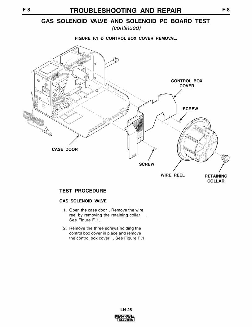
TROUBLESHOOTING AND REPAIR F-8F-8
LN-25
TEST PROCEDURE
GAS SOLENOID VALVE
1. Open the case door . Remove the wirereel by removing the retaining collar .See Figure F .1.
2. Remove the three screws holding thecontrol box cover in place and removethe control box cover . See Figure F .1.
GAS SOLENOID VALVE AND SOLENOID PC BOARD TEST(continued)
FIGURE F.1 Ð CONTROL BOX COVER REMOVAL.
DESIREDIN/MIN
ARCVOLTS
USED
CCWIRE
SPEEDSETTING
(HI of LOWRANGE)
M
-15242
PRESETTING
CCMODE
WIRESPEED:
Selecthorisontal
linefor
DESIRED
IN/MIN.
Selectdiagonal
linefor ARC
VOLTS
USED.
Determine
verticalline
wherelines
cross.
Thisvertical
lineis
CCWIRE
SPEED
SETTING,
onfront
dial.
Setswitch
toCC,
andset
proper
ARCVOLTS
whileweldi
(Seeexample
for 375IN/MIN
at29
VOLTS.)
WIRESPEED
CALIBRATED
ININ/MIN
WIRESPEED
CALIBRATED
PERGRAPH
VARIABLE
WIRE
SPEEDFOR
CC
POWERSOURCE
CONSTANT
WIRE
SPEEDFOR
CV
POWERSOURCE
WIRE
FEED
MORE
1.
2.
3.
4.
5.
700
650
600
550
500
450
400
350
300
250
200
150
100
5050
100150
200250
300350
400450
500550
600650
700
35
31
29
27
25
23
21
19
17
15
C O L DI N C HT13086-99
CASE DOOR
CONTROL BOXCOVER
SCREW
WIRE REEL RETAININGCOLLAR
SCREW

TROUBLESHOOTING AND REPAIR F-9F-9
LN-25
3. Locate and remove the two solenoidleads from the solenoid valve (Forcodes 9812 and below, remove thetwo leads from the solenoid PCboard). See Figure F.2.
4. Make sure the gas supply for thesolenoid is hooked up, and then apply12 VDC to the gas solenoid.
5. If the solenoid activates and allowsgas flow, then the solenoid valve isgood.
NOTE: There should not be any gas flowuntil the solenoid is activated.
6. If the solenoid does not activate andallow gas flow, then the solenoid isfaulty. Replace.
7. The normal solenoid resistance isapproximately 20 to 27 ohms.
GAS SOLENOID VALVE AND SOLENOID PC BOARD TEST(continued)
FIGURE F.2 – SOLENOID LEADS.
SOLENOID LEADSSOLENOID LEADS

TROUBLESHOOTING AND REPAIR F-10F-10
LN-25
SOLENOID PC BOARD
1. Apply at least 25 VDC but no morethan 100 VDC to the LN-25 from theelectrode cable to the work sensinglead. Make sure the polarity switch isset to match the polarity of theelectrode cable. For example, if theelectrode cable is positive and thework sensing lead is negative, set thepolarity switch to posit ive. SeeFigure F.3.
GAS SOLENOID VALVE AND SOLENOID PC BOARD TEST(continued)
FIGURE F.3 Ð APPLIED VOLTAGE POLARITY.
ELECTRODE CABLE
POLARITYSWITCH
WORKSENSING LEAD

TROUBLESHOOTING AND REPAIR F-11F-11
LN-25
2. Check for the presence of the DCvoltage applied from lead 624A(+) tolead 621(-). See Figure F .4 andFigure F .5.
3. Check for the presence of 12 VDCfrom lead 512(+) to lead 621(-).
4. Check for the presence of 10 VDCfrom lead 606(+) to lead 621(-). Whenthe LN-25 trigger circuit is activated,the voltage should drop to about1 VDC.
5. If the above voltage readings aregood and the solenoid valve is
functional, the solenoid PC boardmay be faulty .
6. If the above voltage checks are notcorrect, the control board, contactorboard (if used), remote control board(if used) and/or wiring harness maybe faulty . Refer to the wiring diagramsin the Electrical Diagrams Section.
The appropriate jumper plugs may beused to isolate and check suspectcontactor or remote control boards.
GAS SOLENOID VALVE AND SOLENOID PC BOARD TEST (continued)
FIGURE F.4 Ð PC BOARD FOR K430-1 GAS SOLENOID KIT.
FIGURE F.5 Ð PC BOARD FOR K430 GAS SOLENOID KIT.
624A
512512
624A 621
J11J11621621
606
624A 512 621
M15202M15202

TROUBLESHOOTING AND REPAIR F-12F-12
LN-25
HALL EFFECT MODULE TEST
TEST DESCRIPTION
This test will determine if the hall ef fect module is functioning correctly .
MATERIALS NEEDED
Phillips head screwdriverVolt/OhmmeterDC voltage source (25 to 100 VDC)
Service and repair should only be performed by Lincoln Electric factory trainedpersonnel. Unauthorized repairs performed on this equipment may result indanger to the technician or machine operator and will invalidate your factorywarranty. For your safety and to avoid electrical shock please observe all safetynotes and precautions detailed throughout this manual.
If for any reason you do not understand the test procedures or are unable toperform the test/repairs safely, contact the Lincoln Electric service departmentfor technical troubleshooting assistance before you proceed. Call 216-383-2531or 1-800-833-9353(WELD).
WARNING

TROUBLESHOOTING AND REPAIR F-13F-13
LN-25
TEST PROCEDURE
1. Open the case door. Remove the wirereel by removing the retaining collar.See Figure F.1.
2. Remove the three screws holding thecontrol box cover in place and removethe control box cover. See Figure F.1.
3. Locate the three hall effect leads 500,512 and 555 incorporated in plug J4on the control board (for codes 9812and below, the leads connect directlyto the control board). Do not removethe leads from the control board. SeeFigure F.6 and Figure F.7.
HALL EFFECT MODULE TEST (continued)FIGURE F.6 – CONTROL PC BOARD (CODES 10148 AND ABOVE).
FIGURE F.7 – CONTROL PC BOARD (CODES 9812 AND BELOW).
J4J3J1 J2
541539
555541539
555
500 512
G2196G2196
539 541
512555500
G1757G1757

TROUBLESHOOTING AND REPAIR F-14F-14
LN-25
4. Apply at least 25 VDC but no morethan 100 VDC to the LN-25 from theelectrode cable to the work sensinglead. Observe polarity and set polarityswitch.
5. Check for the presence of 12 VDCfrom lead 512(+) to lead 500(-). If the12 VDC is not present or low , thecontrol board may be faulty .
6. Activate the LN-25 trigger circuit,make sure the drive motor is runningand check for the presence of
approximately 6.0 VDC from lead555(+) to lead 500( -). The value of6.0 VDC represents the correctfeedback voltage from the hall ef fectdevice to the control board.
7. If the above voltage reading is notcorrect, the hall ef fect device mayneed to be adjusted (see theMaintenance Section) or replaced.See the Drive Motor and GearboxReplacement and Access to HallEffect Module procedure.
HALL EFFECT MODULE TEST (continued)

TROUBLESHOOTING AND REPAIR F-15F-15
LN-25
WIRE DRIVE MOTOR TEST
TEST DESCRIPTION
The following procedure will determine if the wire drive motor is functional.
MATERIALS NEEDED
Phillips head screwdriverVoltage source (variable 2 to 23 VDC)Volt/Ohmmeter
Service and repair should only be performed by Lincoln Electric factory trainedpersonnel. Unauthorized repairs performed on this equipment may result indanger to the technician or machine operator and will invalidate your factorywarranty. For your safety and to avoid electrical shock please observe all safetynotes and precautions detailed throughout this manual.
If for any reason you do not understand the test procedures or are unable toperform the test/repairs safely, contact the Lincoln Electric service departmentfor technical troubleshooting assistance before you proceed. Call 216-383-2531or 1-800-833-9353(WELD).
WARNING

TROUBLESHOOTING AND REPAIR F-16F-16
LN-25
TEST PROCEDURE
1. Open the case door . Remove the wirereel by removing the retaining collar .See Figure F .1.
2. Remove the three screws holding thecontrol box cover in place and removethe control box cover . See Figure F .1.
3. For codes 10148 and above, separatethe in-line connector (containing thedrive motor leads) located behind themylar insulation. Be sure to identifythe correct in-line connector . There isalso an in-line connector for the hallef fect module behind the mylarinsulation. See Figure F .8. For codes9812 and below , remove the twomotor leads 539(white) and541(black) from the control PC board.See Figure F .7.
4. Apply a variable DC voltage to thedrive motor from lead 541(black)(+) tolead 539(white)(-).
5. When the supply voltage is variedfrom 2 to 23 VDC, the drive motorspeed (RPM) should vary accordingly .If the motor does not run or vary inspeed, the motor , gearbox or motorbrushes may be faulty . Check orreplace.
6. Check the resistance between eachof the motor leads [541(black) and539(white)] and the motor case. Theresistance should be very high (atleast 500,000 ohms). If the resistanceis low , the motor is grounded to themotor case and should be replaced.
WIRE DRIVE MOTOR TEST (continued)FIGURE F.8 Ð IN-LINE CONNECTORS BEHIND MYLAR INSULATION.
DRIVE MOTORLEAD IN-LINECONNECTOR
HALL EFFECT MODULELEAD IN-LINECONNECTOR

TROUBLESHOOTING AND REPAIR F-17F-17
LN-25
CONTACTOR TEST
TEST DESCRIPTION
The following test will determine if the contactor is functional.
MATERIALS NEEDED
Phillips head screwdriver12 VDC supplyVolt/Ohmmeter
Service and repair should only be performed by Lincoln Electric factory trainedpersonnel. Unauthorized repairs performed on this equipment may result indanger to the technician or machine operator and will invalidate your factorywarranty. For your safety and to avoid electrical shock please observe all safetynotes and precautions detailed throughout this manual.
If for any reason you do not understand the test procedures or are unable toperform the test/repairs safely, contact the Lincoln Electric service departmentfor technical troubleshooting assistance before you proceed. Call 216-383-2531or 1-800-833-9353(WELD).
WARNING

TROUBLESHOOTING AND REPAIR F-18F-18
LN-25
TEST PROCEDURE
1. Open the case door . Remove the wirereel by removing the retaining collar .See Figure F .1.
2. Remove the three screws holding thecontrol box cover in place and removethe control box cover . See Figure F .1.
3. Separate the two in-line connectorslocated behind the reel standassembly . See Figure F .9. For codes9812 and below , remove the twocontactor coil leads from thecontactor PC board. See Figure F .10.
CONTACTOR TEST (continued)
FIGURE F.9 Ð CONTACTOR LEAD IN-LINE CONNECTORS.
IN-LINECONNECTORS

TROUBLESHOOTING AND REPAIR F-19F-19
LN-25
4. Apply 12 VDC to the contactor coilleads.
Do not leave the 12 VDC applied to thecontactor coil for a prolonged period oftime (15 seconds maximum). Damage tocontactor may result.
5. If the contactor does not activatewhen the 12 VDC is applied, thecontactor is faulty. Replace.
6. If the contactor activates when the 12VDC is applied, check the resistancebetween the two large terminal studswith the contactor activated. The
resistance should be very low (0 to1 ohm).
7. If the resistance is “high” or “open”between the two large terminal studswhen the contactor is activated, thecontactor is faulty. Replace.
8. If the contactor activates and theresistance between the terminals islow when the 12 VDC is applied, thecontactor is good.
NOTE: When the contactor is not activated,the resistance between the terminals shouldbe very high (infinite). If the resistance isalways low, the contacts are “stuck” and thecontactor is faulty. Replace.
CONTACTOR TEST (continued)
FIGURE F.10 – CONTACTOR PC BOARD (CODES 9812 AND BELOW).
J6
J7
CONTACTORCOIL LEADS
S20963S20963
CAUTION

TROUBLESHOOTING AND REPAIR F-20F-20
LN-25
CONTACTOR PC BOARD REPLACEMENT
TOOLS REQUIRED
Phillips head screwdriver
ELECTRIC SHOCKcan kill.
¥ Observe all safety precautions detailed throughout this manual.Turn of f input power to the wire feeder . Only qualified techniciansshould perform installations, maintenance, and troubleshootingwork on the machine.
WARNING

TROUBLESHOOTING AND REPAIR F-21F-21
LN-25
REPAIR PROCEDURE
1. Observe the static electricityprecautions detailed in PC BoardTroubleshooting Procedures at thebeginning of this section.
2. Open the case door . Remove the wirereel by removing the retaining collar .See Figure F .1.
3. Remove the three screws holding thecontrol box cover in place and removethe control box cover . See Figure F .1.
4. For codes 10148 and above, removeplug J9 and plug J7 from thecontactor PC board. See Figure F .11.
CONTACTOR PC BOARD REPLACEMENT (continued)
FIGURE F.11 Ð CONTACTOR PC BOARD (CODES 10148 AND ABOVE).
J6 J7
J9
S21415S21415

TROUBLESHOOTING AND REPAIR F-22F-22
LN-25
5. For codes 9812 and below , removethe contactor coil leads and plug J7from the contactor PC board. See
Figure F .10. Also for codes 9812 andbelow , remove plug J3 from thecontrol PC board. See Figure F .12.
CONTACTOR PC BOARD REPLACEMENT (continued)
FIGURE F.12 Ð CONTROL PC BOARD PLUG LOCATIONS (CODES 9812 AND BELOW).
J1
J2
J3
J4
G1757G1757

6. Remove the four screws from thefront panel holding the contactor PCboard assembly in place. Carefullyremove the contactor PC boardassembly. See Figure F.13.
7. Place the new contactor PC boardassembly in position behind the frontpanel. Secure the contactor PC boardassembly by installing the four screwsinto the front panel.
8. For codes 10148 and above, installplug J9 and plug J7 onto thecontactor PC board. See Figure F.11.
9. For codes 9812 and below, install thecontactor coil leads and plug J7 ontothe contactor PC board. See FigureF.10. Also for codes 9812 and below,install plug J3 onto the control PCboard. See Figure F.12.
10. Install the control box cover andsecure by installing the three screws.See Figure F.1.
11. Install the wire reel and retainingcollar and close the case door. SeeFigure F.1.
TROUBLESHOOTING AND REPAIR F-23F-23
LN-25
CONTACTOR PC BOARD REPLACEMENT (continued)
FIGURE F.13 - CONTACTOR PC BOARD REPLACEMENT.
SCREW
CONTACTOR PCBOARD ASSEMBLY

TROUBLESHOOTING AND REPAIR F-24F-24
LN-25
CONTROL PC BOARD REPLACEMENT
TOOLS REQUIRED
Phillips head screwdriver
ELECTRIC SHOCKcan kill.
¥ Observe all safety precautions detailed throughout this manual.Turn of f input power to the wire feeder . Only qualified techniciansshould perform installations, maintenance, and troubleshootingwork on the machine.
WARNING

TROUBLESHOOTING AND REPAIR F-25F-25
LN-25
REPAIR PROCEDURE
1. Observe the static electricityprecautions detailed in PC BoardTroubleshooting Procedures at thebeginning of this section.
2. Open the case door . Remove the wirereel by removing the retaining collar .See Figure F .1.
3. Remove the three screws holding thecontrol box cover in place and removethe control box cover . See Figure F .1.
4. For codes 10148 and above, removethe four plugs J1, J2, J3 and J4. SeeFigure F .14A.
5. For codes 9812 and below , removethe four plugs J1, J2, J3 and J4. Also,tag and remove the five individualleads (three hall ef fect leads 500, 512and 555 and two drive motor leads539 and 541) connected to the controlPC board. See Figure F .14B.
6. On older codes, the control PC boardis larger . If necessary , perform theContactor PC Board Replacementprocedure to remove the contactorPC board. If installed, the remotecontrol PC board may have to beremoved.
CONTROL PC BOARD REPLACEMENT (continued)
FIGURE F.14A Ð CONTROL PC BOARD PLUG LOCATIONS (CODES 10148 AND ABOVE).
J4J3J1 J2
G2196G2196
539 541
512555500
G1757G1757
FIGURE F.14B Ð CONTROL PC BOARD (CODES 9812 AND BELOW).

7. Remove the eight screws holding thecontrol PC board to the inside of thecase. Carefully remove the controlboard. See Figure F.15.
8. Place the new control PC board inposition inside the case. Secure thecontrol PC board by installing theeight screws from the outside of thecase.
9. For codes 10148 and above, installthe four Molex type plugs J1, J2, J3and J4 onto the control PC board.See Figure F.14A.
10. For codes 9812 and below, install thefour Molex type plugs J1, J2, J3 andJ4. Also, connect the five individualleads to the control PC board. Ifnecessary, refer to the wiringdiagrams in the Electrical DiagramsSection. See Figure F.7.
11. Install the control box cover andsecure by installing the three screws.See Figure F.1.
12. Install the wire reel and retainingcollar and close the case door. SeeFigure F.1.
CONTROL PC BOARD REPLACEMENT (continued)
FIGURE F.15 – CONTROL BOARD REPLACEMENT.
TROUBLESHOOTING AND REPAIR F-26F-26
LN-25
SCREW
CONTROLPC BOARD

TROUBLESHOOTING AND REPAIR F-27F-27
LN-25
CONTACTOR REPLACEMENT
TOOLS REQUIRED
Phillips head screwdriver5/16" nutdriver11/16" wrench
ELECTRIC SHOCKcan kill.
• Observe all safety precautions detailed throughout this manual.Turn off input power to the wire feeder. Only qualified techniciansshould perform installations, maintenance, and troubleshootingwork on the machine.
WARNING

TROUBLESHOOTING AND REPAIR F-28F-28
LN-25
REPAIR PROCEDURE
1. Open the case door . Remove the wirereel by removing the retaining collar .See Figure F .1.
2. Remove the three screws holding thecontrol box cover in place and removethe control box cover . See Figure F .1.
3. Remove the baf fle from in front of thecontactor . See Figure F .16.
4. Remove the 5/16" screw holding thecontactor in place.
5. Remove the two 1 1/16" brass nutsholding voltage sensing lead 67 andthe welding cables to the contactor .
CONTACTOR REPLACEMENT (continued)
FIGURE F.16 - CONTACTOR REPLACEMENT.
VOLTAGE SENSINGLEAD 67
WELDING CABLES
CONTACTOR
BAFFLE
5/16" SCREW
REEL STANDASSEMBLY
IN-LINECONNECTORS
11/16" BRASSNUTS

TROUBLESHOOTING AND REPAIR F-29F-29
LN-25
6. Disconnect the contactor coil leads byseparating the two in-line connectorsbehind the reel stand assembly . Forcodes 9812 and below , remove thetwo contactor coil leads from thecontactor PC board. See Figure F .10.
7. Cut or remove any cable t ies orharness tape as necessary .
8. Carefully remove the contactor fromthe LN-25.
9. Install a new contactor in the LN-25.
10. Connect the contactor coil lead in-lineconnectors behind the reel standassembly . See Figure F .16. For codes9812 and below , install the contactorcoil leads onto the contactor PCboard. See Figure F .10.
11. Install the welding cables and voltagesensing lead 67 to the contactor andsecure with the two 1 1/16" brass nuts.See Figure F .16.
NOTE: Be sure brass nuts are tight.11 ft-lb torque is recommended.
12. Install the 5/16" screw to secure thecontactor in place.
13. Install the baf fle in front of thecontactor .
14. Install the control box cover andsecure by installing the three screws.See Figure F .1.
15. Install the wire reel and retainingcollar and close the case door . SeeFigure F .1.
CONTACTOR REPLACEMENT (continued)

TROUBLESHOOTING AND REPAIR F-30F-30
LN-25
GAS SOLENOID VALVE AND/OR SOLENOID PC BOARDREPLACEMENT
TOOLS REQUIRED
Phillips head screwdriver3/4" wrenchPliers
ELECTRIC SHOCKcan kill.
¥ Observe all safety precautions detailed throughout this manual.Turn of f input power to the wire feeder . Only qualified techniciansshould perform installations, maintenance, and troubleshootingwork on the machine.
WARNING

TROUBLESHOOTING AND REPAIR F-31F-31
LN-25
REPAIR PROCEDURE
1. Open the case door. Remove the wirereel by removing the retaining collar.See Figure F.1.
2. Remove the three screws holding thecontrol box cover in place and removethe control box cover. See Figure F.1.
NOTE: If only the gas solenoid valve needsreplacing, it may not be necessary todisconnect all of the wiring. Disconnectwiring only as needed.
3. For codes 10148 and above, removeplug J11 from the solenoid PC board.Also, disconnect the two solenoidleads from the gas solenoid valve,and disconnect the purge switchleads. See Figure F.17.
GAS SOLENOID VALVE AND/OR SOLENOID PC BOARDREPLACEMENT (continued)
FIGURE F.17 – GAS SOLENOID ASSEMBLY WIRING (CODES 10148 AND ABOVE).
SOLENOIDPC BOARD
GAS SOLENOIDVALVE
SOLENOIDLEADS
PLUG J11
PURGE SWITCHLEADS

TROUBLESHOOTING AND REPAIR F-32F-32
LN-25
4. For codes 9812 and below , removethe two solenoid leads from thesolenoid PC board and disconnect thepurge switch leads. See Figure F .18.Also, remove plug J2 from the controlboard. See Figure F .12.
5. Remove the gas hose from the gassolenoid nipple. Remove the brassfitting connected to the gas solenoidvalve from the outside of the case.See Figure F .19.
6. Remove the two screws mounting thegas solenoid and assembly bracket tothe case. Carefully remove theassembly .
7. Remove the two screws mounting thegas solenoid valve to the assemblybracket. Remove the gas solenoidvalve.
8. Remove the two screws mounting thesolenoid PC board to the assemblybracket. Remove the solenoid PCboard.
9. Install the replacement solenoid PCboard onto the assembly bracket andsecure with the two mounting screws.
10. Install the replacement gas solenoidvalve onto the assembly bracket andsecure with the two mounting screws.
11. Install the gas solenoid assemblybracket into the case and secure withthe two mounting screws.
12. Install the gas hose onto the gassolenoid nipple. Install the brassfitting into the solenoid valve from theoutside of the case.
13. For codes 10148 and above, installplug J1 1 onto the solenoid PC board.Connect the leads to the gas solenoidvalve and purge switch. See FigureF.17.
GAS SOLENOID VALVE AND/OR SOLENOID PC BOARDREPLACEMENT (continued)
FIGURE F.18 Ð SOLENOID ASSEMBLY WIRING (CODES 9812 AND BELOW).
SOLENOIDPC BOARD
SOLENOIDLEADS
PURGE SWITCHLEADS

14. For codes 9812 and below, install thetwo leads from the gas solenoid valveonto the solenoid PC board andconnect the purge switch leads. SeeFigure F.18. Also, install plug J2 ontothe control board. See Figure F.12.
15. Install the control box cover andsecure by installing the three screws.See Figure F.1.
16. Install the wire reel and retainingcollar and close the case door. SeeFigure F.1.
TROUBLESHOOTING AND REPAIR F-33F-33
LN-25
GAS SOLENOID VALVE AND/OR SOLENOID PC BOARDREPLACEMENT (continued)
FIGURE F.19 – GAS SOLENOID VALVE AND SOLENOID PC BOARD REPLACEMENT.
BRASSFITTING
GAS SOLENOIDASSEMBLYMOUNTING
SCREW
GAS SOLENOIDVALVE MOUNTINGSCREW
SOLENOIDPC BOARD
PC BOARDMOUNTING
SCREW
GAS SOLENOIDASSEMBLY BRACKET
GAS HOSE
GAS SOLENOIDNIPPLE
GAS SOLENOIDVALVE

TROUBLESHOOTING AND REPAIR F-34F-34
LN-25
DRIVE MOTOR AND GEARBOX REPLACEMENT ANDACCESS TO HALL EFFECT MODULE
TOOLS REQUIRED
Phillips head screwdriver3/4" wrench5/8" wrench7/16" wrenchSlot head screwdriver
ELECTRIC SHOCKcan kill.
¥ Observe all safety precautions detailed throughout this manual.Turn of f input power to the wire feeder . Only qualified techniciansshould perform installations, maintenance, and troubleshootingwork on the machine.
WARNING

TROUBLESHOOTING AND REPAIR F-35F-35
LN-25
REPAIR PROCEDURE
1. Observe the static electricityprecautions detailed in PC BoardTroubleshooting Procedures at thebeginning of this section.
2. Open the case door . Remove the wirereel by removing the retaining collar .See Figure F .1.
3. Remove the three screws holding the
control box cover in place and removethe control box cover . See Figure F .1.
4. For codes 10148 and above, separateboth in-line connectors behind themylar insulation. See Figure F .20. Forcodes 9812 and below, remove thetwo armature leads (539 and 541)and the three hall ef fect module leads(500, 512 and 555) from the controlboard. See Figure F .7.
DRIVE MOTOR AND GEARBOX REPLACEMENT AND ACCESS TOHALL EFFECT MODULE (continued)
FIGURE F.20 Ð WIRE DRIVE ASSEMBLY REPLACEMENT.
ELECTRODECABLE
1/2" BOLT
MYLARINSULATION IN-LINE
CONNECTORS
WIRE DRIVEASSEMBLY
WIRE DRIVE ASSEMBLYMOUNTING BOLTS(4 PLACES)

TROUBLESHOOTING AND REPAIR F-36F-36
LN-25
5. Remove the 1/2" bolt securing theelectrode cable to the gear boxconductor block. Remove the fourbolts mounting the wire driveassembly to the bottom of the case.See Figure F .20.
6. Carefully remove the wire driveassembly . See Figure F .21.
7. Remove the two screws andlockwashers holding the rear endplate to the gearbox and remove therear end plate. Remove the threedrive motor mounting screws, flatwashers and lockwashers (one isinside the gearbox housing).
8. Carefully remove the drive motor fromthe gearbox.
9. Install the replacement drive motoronto the gearbox and secure with thethree screws, f lat washers andlockwashers. Install the rear endplate, lockwashers and screws.
10. Posit ion the wire drive assemblyinside the case and secure to thebottom of the case with the four bolts.Secure the electrode cable to theconductor block with the 1/2" bolt.See Figure F .20.
11. For codes 10148 and above, connectboth in-line connectors and positionthem behind the mylar insulation. SeeFigure F .20. For codes 9812 andbelow, install the two armature leads(539 and 541) and the three hallef fect module leads (500, 512 and555) onto the control board. SeeFigure F .7.
12. Install the control box cover andsecure by installing the three screws.See Figure F .1.
13. Install the wire reel and retainingcollar and close the case door . SeeFigure F .1.
DRIVE MOTOR AND GEARBOX REPLACEMENT AND ACCESS TOHALL EFFECT MODULE (continued)

TROUBLESHOOTING AND REPAIR F-37F-37
LN-25
DRIVE MOTOR AND GEARBOX REPLACEMENT AND ACCESS TOHALL EFFECT MODULE (continued)
FIGURE F.21 Ð DRIVE MOTOR REPLACEMENT.
DRIVEMOTOR
GEARBOX
REAR END PLATE
LOCKWASHER
END PLATEMOUNTING SCREW
FLAT WASHER
LOCKWASHER
DRIVE MOTORMOUNTING SCREW

TROUBLESHOOTING AND REPAIR F-38F-38
LN-25
RETEST AFTER REPAIR
If a failed test indicates that any mechanical part that could af fect the machineÕs electricalcharacteristics must be replaced or if any electrical components are repaired or replaced,the machine must be retested and meet the following standards.
Wire Feed Speed . . . . . . . . . . . . . . . . . . . . . . . . . . . 50 through 700 Inches Per Minute
Voltmeter . . . . . . . . . . . . . . . . . . . . . . . . . . . Must be operative from 0 through 40 VDC
Gas Solenoid (optional) . . . . . . . . . . . . . . . . Must operate when gun trigger is activated
Contactor (optional) . . . . . . . . . . . . . . . . . . . Must operate when gun trigger is activated

TABLE OF CONTENTS- ELECTRICAL DIAGRAMS SECTION -
LN-25
Electrical Diagrams . . . . . . . . . . . . . . . . . . . . . . . . . . . . . . . . . . . . . . . . . Section GWiring Diagrams
Codes 10148 and Above . . . . . . . . . . . . . . . . . . . . . . . . . . . . . . . . G-3Codes 9812 and Below . . . . . . . . . . . . . . . . . . . . . . . . . . . . . . . . . G-4
Operating SchematicsCodes 10148 and Above . . . . . . . . . . . . . . . . . . . . . . . . . . . . . . . . G-5Codes 9812 and Below . . . . . . . . . . . . . . . . . . . . . . . . . . . . . . . . . G-6
Control PC Board LayoutCodes 10148 and Above . . . . . . . . . . . . . . . . . . . . . . . . . . . . . . . . G-7Codes 9812 and Below . . . . . . . . . . . . . . . . . . . . . . . . . . . . . . . . . G-9
Contactor PC Board LayoutCodes 10148 and Above . . . . . . . . . . . . . . . . . . . . . . . . . . . . . . . . G-11Codes 9812 and Below . . . . . . . . . . . . . . . . . . . . . . . . . . . . . . . . . G-13
Section G

NOTES G-2G-2
LN-25

G-3ELECTRICAL DIAGRAMS
LN-25
WIRING DIAGRAM — CODES 10148 AND ABOVE
530C
1 23 4
J6
J7
*
*
530
530B50
0
1
2
3
4
5
6
530A512606607530500
HI LO
523522
667500530621607606512
530A
VM
ARCVOLTMETER
+
667 621
632633
63110K
R1
WIRE SPEEDCONTROL RHEOSTATN.B.
CONTACTORP C BOARD
OPTIONALTIMERPLUG
S2
S3
S1
TO WORK CLIP
BLACK
POS
667
621
67
N.B.
NEG
ABCDE
622A
500A
J5TRIGGERCONNECTOR
7
*J3
3214
2134
621
621
500A667
622A
606512
624A
*
*J2
J1
N.D.
3 6 1 4 10 8 11 2 9
509
632
523
522
633
523
524
631
BLA
CK
BLU
ER
ED
524
523
509
VV CV
N.B.
WH
ITE
539
BLA
CK
541
530B500
530
530C530B
N.B. ,N.D.B
LAC
K
RED
BLU
E
HALLEFFECTSWITCH
GUN CABLE
N.F.
N.G.
N.D.,N.E.N.A.
S4
N.F.
N.B.
WIRE FEEDMODE SWITCH
POLARITYSWITCH
WIRE SPEED DIAL RANGE SWITCH
COLD INCH
SWITCH PUSHBUTTON
,N.H.
624
11193286574
13141210
J9 *
667621
*41 23
1 2
BLA
CK
WH
ITE
J13
159
16131210148
11165324
13
539
14
541
7 12 5
BLA
CK
WH
ITE
OPTIONAL REMOTEKIT PLUG
CONTROLP.C. BOARD
LEGENDS1 POLARITY SWITCHS2 WIRE SPEED DIAL RANGE SWITCHS3 WIRE FEED MODE SWITCHS4 COLD INCH SWITCH
622A621500A530A530624606622607512
4321
500
*J8
*J13
123456789101112
7576
77
R3ARC VOLTS
TO CONTROL BOARDTO TIMER P.C. BOARD
3433
4 21
CLEVELAND, OHIO U.S.A.
8-12-94C
L9644
WIRING DIAGRAM - LN-25
702
622A621500A530A530624606622607512
43
70027011
500
*J8
*J13
123456789
101112
ABCDEF
757677
7576
77R3
ARC VOLTS
TO CONTROL BOARD
REMOTEP.C. BOARD
TOPOLARITYSWITCH
4333421757677
667
621
ABCDEFGHI
667621
REMOTEP.C. BOARD
I I I I I I
N.E.
N.F.
CONTACTOR CAN BE INSTALLED IN UNITS WITH A G1757-3 (OR HIGHERPART NO.) CONTROL PC BOARD.
WHEN A CONTACTOR IS NOT USED, THE '67' LEAD TO THE POLARITYSWITCH COMES FROM THE CONDUCTOR BLOCK AND THE INPUT CABLECONNECTS DIRECTLY TO THE CONDUCTOR BLOCK.
N.H. TOGGLE SWITCH USED ON EARLIER UNITS.
N.G. JUMPER PLUG MUST BE INSTALLED UNLESS OPTIONAL TIMER IS USED.
N.A.
N.B.
WHEN A CONTACTOR IS NOT USED THE JUMPER PLUG MUST BEINSTALLED UNLESS OPTIONAL REMOTE KIT IS BEING USED.
CONNECTIONS AS VIEWED FROM BACK OF RHEOSTAT AND SWITCHES.
N.D. ITEM FACTORY INSTALLED ON SOME MODELS AND OPTIONAL EQUIPMENTON SOME MODELS.
NOTES
U B R
OPTIONAL PULSE POWER ADAPTOR KIT
OPTIONAL REMOTE OUTPUT CONTROLTO TIMER P.C. BOARD
500
555
512
*J4
*
606500512607530A530
J10
TIMER P.C.BOARD
TO REMOTEOR CONTACTOR
P.C. BOARD123456
GASSOLENOIDVALVE
N.D.
PURGE
608
608621
512624A
606
N.D.
621
1
53 7 6 8 42
GAS SOLENOIDP C BOARD *J11
67
CONTACTOR
CONTACTOR COIL
N.F.
N.D.,N.E.
INPUTCABLE
N.F.
CONNECTOR CAVITY NUMBER*
500A
607622A512530A667624500A530606621622A
750015
916131210148
11165324
*J6
1 2 3 4 5 6N.G.
530530A607512500606
*J6
1 2 3 4 5 6N.G.
530530A607512500606
700701702
500
607622512530A
624500A530606621622A
622A621500A530A530624606622607512
8765
500
*J8
*J12
123456789
101112
ABCDEF
41422
7576
77R3
ARC VOLTS
TO CONTROL BOARD
REMOTEP.C. BOARD
TO TIMER P.C. BOARD
*J6
1 2 3 4 5 6N.G.
530530A607512500606
4321 2
41424
GH
4
757677
OPTIONAL 42 VOLT REMOTE OUTPUT CONTROL
757677
OPTIONAL REMOTE VOLTAGE CONTROL
7576
77
R3ARC VOLTS
ABCDEF
OPTIONAL TIMER KIT
SOLENOID P.C.BOARD PLUG
OPTIONALCONTACTORP.C. BOARD PLUG
NOTE: This diagram is for reference only. It may not be accurate for all machines covered by this manual. The specific diagram for a particular code is pasted inside the machine on one of the enclosure panels.

G-4ELECTRICAL DIAGRAMS
LN-25
WIRING DIAGRAM — CODES 9812 AND BELOW
530C
1 23 4
J6
J7
*
*
530
530B50
0
1
2
3
4
5
6
530A512606607530500
HI LO
523522
667500530621607606512
530A
VM
ARCVOLTMETER
+
667 621
N.D.
632633
63110K
R1
WIRE SPEEDCONTROL RHEOSTATN.B.
CONTACTORP C BOARD
OPTIONALTIMERPLUG
S2
S3
S1
TO WORK CLIP
BLACK
POS
667
667
621
621
67
N.B.
NEG
ABCDE
622A
500A
J5TRIGGERCONNECTOR
ARC SOLENOIDP C BOARD
GASSOLENOIDVALVE
N.D.
PURGE
621
608
608621
512624A
606
N.D.500
607622512530A667
624500A530606621622A
500
607622512530A667
624500A530606621622A
1
10
23456
789
1112
*J3
1234
1234
621
621
500A667
622A
606512
624A
*
*J2
J1
SOLENOID P CBOARD PLUG
N.D.
1 2 3 4 5 6 7 8 9
509
632
523
522
633
523
524
631
512
500
555
BLA
CK
BLU
ER
ED
524
523
509
VV CV
N.B.
BLACK
WHITE539
541
WH
ITE
539
BLA
CK
541
530B500
530
530C530B
N.B. ,N.D.B
LAC
K
RED
BLU
EH
ALL
EFFE
CT
MO
DU
LE
67
CONTACTOR
CONTACTOR COIL
N.F.
GU
N C
ABLE
N.F.
N.G.
N.D.,N.E.
CONTACTORP C BOARD PLUG
N.A.
OPTIONAL REMOTEKIT PLUG
*J4
CONTROLP C BOARD
N.D.,N.E.
S4
ELECTRICAL SYMBOLS PER E1537
LEGENDS1 POLARITY SWITCHS2 WIRE SPEED DIAL RANGE SWITCHS3 WIRE FEED MODE SWITCHS4 COLD INCH SWITCH
INPUTCABLE
NOTES
N.A. WHEN A CONTACTOR IS NOT USED THEJUMPER PLUG MUST BE INSTALLED UNLESSOPTIONAL REMOTE KIT IS BEING USED.
N.B. CONNECTIONS AS VIEWED FROM BACK OF RHEOSTAT AND SWITCHES.
N.D. ITEM FACTORY INSTALLED ON SOME MODELS ANDOPTIONAL EQUIPMENT ON SOME MODELS.
N.E. CONTACTOR CAN BE INSTALLED IN UNITS WITH AG1757-3 (OR HIGHER PART NO.) CONTROLP C BOARD.
N.F. WHEN A CONTACTOR IS NOT USED, THE '67' LEAD TO THE POLARITY SWITCH COMES FROM THECONDUCTOR BLOCK AND THE INPUT CABLE CONNECTS DIRECTLY TO THE CONDUCTOR BLOCK.
N.G. JUMPER PLUG MUST BE INSTALLED UNLESSOPTIONAL TIMER IS USED.
LEAD TO THE TRIGGER SWITCH. ON THE G1757-1P C BOARD A 5 AMP FUSE WAS USED TO INTERRUPTTHE 667 LEAD.
/
N.F.
N.B.
CONNECTOR CAVITY NUMBER
CAVITY NUMBERING SEQUENCE (COMPONENT SIDE OF BOARD)
*
J2 J6J1,J7 J4 J3
WIRE FEEDMODE SWITCH
POLARITYSWITCH
WIRE SPEED DIAL RANGE SWITCH
COLD INCH
SWITCH PUSHBUTTON
,N.H.
TOGGLE SWITCH USED ON EARLIER UNITS.
N.H.
624
9-1
3-91
B
W
IRIN
G D
IAG
RAM
75
45
L
N.C.
N.C. FUSE USED ON EARLIER MODELS ONLY:ON G1757-2 THRU G1757-5 CONTROL P C BOARDS,
A 1 8 AMP FUSE INTERRUPTS THE 500A.
NOTE: This diagram is for reference only. It may not be accurate for all machines covered by this manual. The specific diagram for a particular code is pasted inside the machine on one of the enclosure panels.

G-5ELECTRICAL DIAGRAMS
LN-25
OPERATING SCHEMATIC — CODES 10148 AND ABOVE
D22
150K
R62
X713
10
11
13.7K
R64 22.1K
R67
D13
5W3300
R72
D18
40V600mAQ12
150K
R66
D21
X72
5
4
D25
D23
15.0K
R69
10K
R63
10K
R76
X71
6
7
D24
22.1K
R68
44.2K
R651.8
20V
C30
1.820V
C31
OVER-VOLTAGE
22.1K
R71 15.0K
R74
26.7K
R75
D19
X714
8
9
1.035V
C32
D20
512
33.2K
R78
512509
667
SHUT DOWN
26.7K
R70
15.0K
R77
100
R73
500p
C15
2.8K
R55
1.00K
R98
X68
10
9102K
R54
500p
X67
6
516.5KR51
J41
667
J22
F-V CONVERTER10K
R18
J45
J47
J412
44.2KR50
J410
J42
J24
J21
J11
J13
6.81K
R95
1815V
C14
LM2907
ISOURCE
GND
NC
TACH INPUT
NC
TACH INPUT
ISINK
NC
IBIAS
IBIAS
Ic
V+
NC
/X4
11
10
13
8
12
2
1
6
4
9
7
5
14
3
1.00K
R97
10K
R19
100K
CW
R22
68.1K
R23
22.1KR21
.3350V
C17
100V100pC13
200V.0033C16
22.1K
R20
X61
2
3
13.7K
R52
4.75KR85
X614
12
13
4.75K
R94
44.2K
R53
4.75KR84
509
J12
512
J14
J43
J23
J411
D14
10K
R24
J46
J48
J44
1.00K
R99
40V600mAQ5
X92
5
4
3.32K
R32
3.32K
R25
C28
150K
R33
1815V
C19
X91
6
7
400V.001C21
22.1K
R30
40V600mAQ10
D11
10K
R26
1.00MR27
1815V
C18
5.62K
R28
5025VC23D10
600mA40V
Q11 22.1K
R29
1025V
C22
18.2K
R31
X814
9
8
14
7
/Q2
D1
VDDQ1
SET 2
CLOCK 2
/Q1 Q2
CLOCK 1
VSS
RESET 1
MC14013B
SET 1 D2
RESET 2
X10
11
10
13
8
12
2
1
6
4
9
5
3
1.820V
C7
OSCILLATOR
PWM
512
4 KHZ
SUPPLY -9V DC
512
ACTUAL SPEEDBUFFER
NEGATIVE
SET-SPEED SCALER/BUFFER
COMPARATOR
22.1K
R34X58
10
9 C20
26.7K
R35
X57
5
6
D8
5W3300
R86
624A
621
TRIGGER622ACONNECTOR
SOLENOIDTO ARC
512PCB
606
SWITCHPOLARITY
667
500A
621
SWITCH
MODE SWITCH
SPEEDWIRE
CONTROL
DIAL RANGE
WIRE FEED
WIRE SPEED
TRIGGER SENSING
621
J312
J37
J316
J33
J39
J315
J310
J314
J311
J313
J38
J32
J35
J31
J36
C3
OPTIONALCONTACTOR
PCB PLUG
530A
JUMPERPLUGREMOTE
J34
470350V
C240V600mAQ3
150V45J
TP1
18.2K
R6
2.67K
R8
100
R3
J49
C-
FRAME CONNECTION
CURRENT LIMITING
621
667
624
500A
512
MAX 631
2194
EARTH GROUND CONNECTION
POWER SUPPLY SOURCE POINT
LN-25 CONTROL BOARD
VOLTAGE NET
G
100
(
GENERAL INFORMATION
ELECTRICAL SYMBOLS PER E1537
UNLESS OTHERWISE SPECIFIED)(UNLESS OTHERWISE SPECIFIED)
UNLESS OTHERWISE SPECIFIED)
LAST NO. USED
49
R-
LABELS1A, 400V
COMMON CONNECTION
32D-
SUPPLY
FILE: G2194_1AJ
22.1K
R49
.17WR
47
C36
LM2901
X7
3
12
C41
C34
C35 C37
4066B
X11
14
7
LM2901
X9
3
12
C42
X82
5
4
C33
NOTES :
LM224
X6
4
11
40V600mAQ13
100K
R61
1.00K
R83
X813
11
10
1815V
C25
1.00K
R1004N35OCI1
1
2
22.1K
R82
1.00K
R81
22.1KR79
D29
D28
512
NUMBER.
22.1K
R80
X81
7
6
C39
LM2901
X8
3
12
C40
MC14013B
X10
7
14
1.035V
C29
100V100pC48
C38
LM224
X5
4
11
10K
R60
22.1K
R90
200mA7.5-9.0 V
Q15
4.735V
C452.43K
R88
1W12VDZ1
40V600mAQ14
C47
D7
2050V
C10
5W4700
R14
X5
3
1
2
4.735V
C27
26.7K
R59
40V600mAQ4
1.00K
R9
13.7K
R10
4584B
X3
14
7
D5
D17
512
500p
512
500p
509
495
509
621
7.68K
R87
+9.50VDC10.0
R4
4.75K
R7
+
REF
-TL431
X2
1
6
8
470350V
C9667
1W16VDZ4
621
600V.05C1
5W10R1
400V
5A
Q1
5025V
C4
512
5W4700
R13
330050V
C5
100
R5
X365
D32
400V300mA
Q2
5W3300R
2
D21N4005D4
1N4005D1
1N4005D27
470350V
C8
+
REF
-TL431
X1
1
6
8
+12VDC
D3
15A600V
D6
DYNAMIC BRAKING
J413
1W16VDZ2
16A35V
D31
20A500V
Q9
J414
100
R17
6.81K
R44
600V3AD12
600mA40V
Q7
5.62K
R36
40V600mAQ6
100
R37
20A500V
Q8
1W16VDZ3
5W68
R38
400V.1C26
47.5K
R46
3.92K
R43
1.50K
R45
100V100pC49
X914
8
9
X31213
512
600V
D3015A
TOMOTOR
541(B)
539(W)
FET DRIVER
D9
7
14
Bin
Vss
Bout
Actrl
Aout
Din
Cin
Ain
Vdd
Bctrl
DctrlCctrl
Cout Dout
4066B
X11
5
6
13
2
4
8
12
3
1
10
11
9
22.1K
R89
400V.001C44
22.1K
R15
4N35OCI1
4
5
6
400V.0022C11
100V100pC46
X321
100K
R16
C12
X343
X31011
X389
633
632
523
522
EFFECT
(B)
555(U)
TO HALL
500
512(R)
V.V.SCALER
523
524
509
SCHEMATIC
.022/50VCAPACITORS = MFD
DIODES =1/4WRESISTORS = Ohms (
WITHOUT AFFECTING THE INTERCHANGEABILITY OF A COMPLETE BOARD, THIS DIAGRAM MAY
SHOOT-THRU PROTECTION
NOT SHOW THE EXACT COMPONENTS OR CIRCUITRY OF CONTROLS HAVING A COMMON CODE
N.A. SINCE COMPONENTS OR CIRCUITRY ON A PRINTED CIRCUIT BOARD MAY CHANGE
606
512
621
624
622A
606
530
OPTIONAL
500
530
530A
PCB PLUG
622
607607
500
621621
500p
621621
512
621495
22.1K
R39
X9
10
13
11
5.62K
R58
2.43K
R42
39.2K
R41
22.1K
R40
400V.001C24
621
512
512
509
ACCELERATION
C43
C61.3K
R91500
CW
R11
4.75K R12
26.7K
R56
267
R57
D16X5
14
12
13
1.00K
R96
7-8-94A
NOTE: Lincoln Electric assumes no responsibility for liablilities resulting from board level troubleshooting. PC Board repairs will invalidate your factory warranty. Individual Printed Circuit Board Components are notavailable from Lincoln Electric. This information is provided for reference only. Lincoln Electric discourages board level troubleshooting and repair since it may compromise the quality of the design and may resultin danger to the Machine Operator or Technician. Improper PC board repairs could result in damage to the machine.

G-6ELECTRICAL DIAGRAMS
LN-25
OPERATING SCHEMATIC — CODES 9812 AND BELOW
LN-25 OPERATING SCHEMATIC
1833 G
RANGE SWITCHHI - LO
632
522523
N.B.
633 631MAX.
10K OHMSR1
WIRE SPEEDCONTROL RHEOSTAT
N.B.
VOLTMETER
VMB + W
N.F.
667 621
523N.B.
WIRE FEEDMODE SWITCH
VV - CV
WIRE SPEED DIAL
524 509
S3
621TO WORKCLIP
BLACK
S1POLARITYSWITCH
POS
67N.B.
NEG
667
667
621
622A
500A
624A
621
512
606
SOLENOIDKIT PLUG
A
B
C
D
E
622A
500A
J5
TRIGGER
CONNECTOR
PURGEN.F.
621
ARC SOLENOID P.C. BD.
SEE SOLENOID KITSCHEMATIC
GAS SOLENOID VALVEN.F.
509
524
522
633
523
632
631
523
606
530
530A
622A
500A
622
500
512
667
624
621
607
CONTACTORP.C. BD. PLUG
606
530
530A
622A
500A
622
500
512
667
624
621
607
N.A.
OPTIONALREMOTE PLUG
N.F., N.G.606
530
530A
500
512
667
621
607
624
3124
SEE CONTACTORKIT SCHEMATIC
J7 *
1
2
3
4
5
6
CONTACTORP.C. BD.
J6 *
530C530B
500500
530C530B
N.B., N.F., N.L.COLD INCHPUSH BUTTON SWITCH
606
500
512
607
530A
530
N.J.
OPTIONALTIMER PLUG
67
GUN CABLE
N.H.
RU
B
HALLEFFECTMODULE
W539
B541
N.F.
CONTACTOR COIL
CONTACTOR
N.H.
INPUT CABLE
X1, X2 TL431IP PRECISION REFERENCEX3 MC14584B HEX SCHMITT TRIGGERX4 LM2907 FREQUENCY TO VOLTAGE CONVERTERX5, X6 LM324 QUAD OP-AMPX7 THRU X9 LM2901 QUAD COMPARATORX10 MC14013B D-TYPE FLIP-FLOP
OCI 4N35 OPTO-COUPLERX11 MC14066B QUAD ANALOG SWITCH
COLOR LEGEND
B = BLACKU = BLUEH = BROWNR = REDG = GREENW = WHITE
NOTES:
N.A. WHEN A CONTACTOR IS NOT USED, A JUMPER PLUG MUST BE INSTALLED UNLESS OPTIONAL REMOTE OUTPUT KIT IS BEING USED.
N.B. CONNECTIONS AS VIEWED FROM BACK OF RHEOSTAT AND SWITCHES.
CHANGE WITHOUT AFFECTING THE INTERCHANGEABILITY OF A COMPLETE BOARD,N.C. SINCE COMPONENTS OR CIRCUITRY ON A PRINTED CIRCUIT BOARD MAY
THIS DIAGRAM MAY NOT SHOW THE EXACT COMPONENTS OR CIRCUITRY OFCONTROLS HAVING A COMMON CODE NUMBER.
N.D. ON G1757-2 THRU G1757-5 P.C. BOARDS, A 1 8 AMP FUSE INTERRUPTS THE/500A. LEAD. ON THE G1757-1 P.C. BOARD A 5 AMP SLOW BLOW FUSE WAS USEDTO INTERRUPT THE 667 LEAD. R72 WAS 1.5K AND THERE WAS NO R86.
N.E. ACTUAL CIRCUIT OF X3.
C
D
E
F12
10
8
6
YX
5
9
11
13
N.F. ITEM FACTORY INSTALLED ON SOME MODELS AND OPTIONAL EQUIPMENTON OTHER MODELS.
N.G. CONTACTOR CAN BE USED WITH A G1757-3 (OR HIGHER PART NO.) CONTROLP.C. BOARD.
N.H. WHEN A CONTACTOR IS NOT USED THE "67" LEAD TO THE POLARITY SWITCHCOMES FROM THE CONDUCTOR BLOCK AND THE INPUT CABLE CONNECTSDIRECTLY TO THE CONDUCTOR BLOCK.
N.J. JUMPER PLUG MUST BE INSTALLED UNLESS OPTIONAL TIMER IS USED.
N.K. R25 WAS 1K ON G1757-3C (OR LOWER PART NO.) P.C. BOARDS.
N.L. TOGGLE SWITCH USED ON EARLIER UNITS.
GENERAL INFORMATION
ELECTRICAL SYMBOLS PER E1537.
CAPACITORS = mfd/VOLTS (.022/25V UNLESS OTHERWISE SPECIFIED).
RESISTORS = OHMS (1/4 WATT UNLESS OTHERWISE SPECIFIED).
DIODES = 1A, 400V (UNLESS OTHERWISE SPECIFIED).
= COMMON CONNECTION
= SOURCE POINT CIRCUIT LOCATION
* = CONNECTOR CAVITY NUMBER
(COMPONENT SIDE OF P.C. BOARD)
12
34
CAVITY NUMBERING SEQUENCE
J2
12
34
J1, J7
12
J6
45
63
12
3
45
6
78
9
J4
12
3
45
6
78
9
1011
12
J3
S2
2
11
7
6
4
1
3
8
12
5
9
10
3
9
6
4
7
5
8
1
2
3
1
4
2
4
1
3
R86
3.3K
5W
*J3
J4 *
J2 *
*J1
D14
X6
3
21
V.V. SCALER
509
R51
R50
2
1
667
R84 R85
R94
4.75K
METALS1%
16.5K1/4W
500p
44.2K
4.75K
500p
4.75K 12
13
X6+
-+
-
14
R956.81K
R52 R54
13.7K 102K
9
10 X6
X6
+
+
-
-
8
75
6
R53
500p
R55
44.2K 2.8K2
1
2
3X5
+
-1
R5626.7K
SET-SPEED SCALER/BUFFER
22.1K R71
R74 R77
R73
R76 R78
D23 15.0K 15.0K
X75
42
+
-
10K D25 33.2K
Q12200mA30V
512
R79 22.1K
TRIGGER SENSING
D24 + C321.035V
R75 26.7K
R72
3.3K5W
D29
D22
X7
X7
14
13
9
8
11
10
15.0K
R70
R69
OVER-VOLTAGESHUT DOWN
26.7K
D21D20
+ C311.820V
D19R
68 22.1KR67
22.1K
512
C301.820V
10KD13
500p
R63
R62
R65
R64
667
150K
+
509
13.7K
R66150K
7
6X7
+
-
1
D18
495
11
4
X5
LM224 LM224LM2901
C34
C35 C37
C36 X6
4
11
C38 X73
12
C39
3
12
X8
LM2901
C40 X93
12LM2901
X1014
7
C41 C42X11
14
7
512
SHOOT-THRU PROTECTION
8
9
4
5
10
11
14
2
13
X8
X8
X8+
+
+
-
-
-
R59
R60
R80
R81
C33
1.00K
22.1K
10K
26.7K
512
R82
512
22.1K
R83
QCI14N35
1
2
Q13200mA30V
D28
1.00K
C291.035V
R61D17
+ C274.735V
R57 267
D16 14X5
12
13
+
-
C28ACCELERATION
R58 5.62K
TACH INPUTIc/IBIASISOURCENCNC
NCNC
GND
IBIASV+
ISINK
TACH INPUT
X4
LM2907
1234567 8
91011121314
509
10KR24C15+C14
1815V
500p
R23
R22
100K
CW
68.1K
C17.33
50V
+C16
200V.0033
22.1K
R21
22.1KR20
512C18 C19
++
18 1815V15V
R271 2
10KR26
C20
D8
X58
9
10
COMPARATOR
R253.32K
ACTUAL-SPEEDBUFFER
X57
6
5C13100p
1000V
R1910K
U
B500
555
R
R18 10K
TO HALL EFFECT512
CONTROL BOARD
R3526.7K
5
4
X9+
- 2
22.1K R30 C21
.001400V PWM
R33 150K
R3118.2K
R29
R3222.1K 3.32K
512
4 KHZOSCILLATOR
X9+
-
7
6
Q2/Q2
D2SET 2
1234567 8
91011121314Q1
/Q1CLOCK 1RESET 1DLSET 1VSS
VDD
CLOCK 2RESET 2
MC14O13B
512
X10
XX
XX
XX
R3422.1K
Q5200mA30V
C43
C49100p1000v
R42
R41
C24.001
400V
509
39.2K
11
10
8
9
X9
X9
+
+
-
-13
14
512
R3922.1K
512
R4022.1K
C48100p1000v
CURRENT LIMITING
2.43K
R43 3.92K
Bin
123 45
67 8
9 1011
12
13 14
Aout
Cart1Vss
VddX11
R4922.1K
C251815V
R451.50K
+
Aatr1
BoutBart1Cout
4066B
Ain
DinDout
Dart1Cin
2
R36
5.62K
Q72N4125
3
Q6200mA30V
512
FET DRIVER
D9R37100
DZ316V1W
R446.81K
R46
47.5K
R47.1
7W
621
Q820A500V D12
3A600V
685WR
38
C26.1
400V
C2325V50
2
R28
5.62K
2N4125
3
200mA30V
512
Q10
Q11
C22+
D10
D11
495-9V DC
X8+
-6
7
NEGATIVESUPPLY
2.43K R88
+
C454.735V
X
R90
22.1KC47
R87
DZ112V1W
+
7
R14
47006W
C1020
50V
X34584B
14Q14200mA30V
D7C12
R16 100K C11
.0022400V
R15
22.1K
OCI14N35
C44.001400V
6 4
5 X3
9
11
13
X3
X3
X3
X3
5
8
10
12
6
R17100
DZ216V1W
20A500V
Q9
15A600V 2
1
35V16AD31
B
W
Q15
1 2R89
22.1K
C46100p1000V
X33 4
DYNAMIC BRAKING
13.7K
4.75K
+
C71.8
500p
R12
R11
R10
CW
500
C6
8REF
X2
6-
+ 1
R911.3K
C5330050V
+
R91.00K
Q42N4123
D5
509+9.50VDC621
C9470350V
R13
47005W470
350V
+ +C8
C45025V+
512+12VDC
D3DZ416V1W
2.67
KR
84.
75K
R7
R6
18.2
K
4 3D6 24A 600V
10.0
100R5
R4
D2
Q1
5A400V
Q2
400V3300
5W
R2C2
470350V
+
R1 10
2W
8X1
6-
+ 1
TL431TL431
R3
100 C3
Q32N4123
D1
D41N4005
D271N4005
621
667
C1
600V.05
TP1150V45J
D32
621
608
N.F.
1N4005
300mA
7.68K
20V
11 25V
10
+
1
F-V CONVERTER1.00M
++
--
100K
100
+
+
-
-
44.2K MC14013B 4066B
D6
1
2
3
REF.
+
7.5-9.0V
3-4-94
NOTE: Lincoln Electric assumes no responsibility for liablilities resulting from board level troubleshooting. PC Board repairs will invalidate your factory warranty. Individual Printed Circuit Board Components are notavailable from Lincoln Electric. This information is provided for reference only. Lincoln Electric discourages board level troubleshooting and repair since it may compromise the quality of the design and may resultin danger to the Machine Operator or Technician. Improper PC board repairs could result in damage to the machine.

DIAGRAMS G-7G-7
LN-25
NOTE: Lincoln Electric assumes no responsibility for liablilities resulting from board level troubleshooting. PCBoard repairs will invalidate your factory warranty. Individual Printed Circuit Board Components arenot available from Lincoln Electric. This information is provided for reference only. Lincoln Electric dis-courages board level troubleshooting and repair since it may compromise the quality of the design andmay result in danger to the Machine Operator or Technician. Improper PC board repairs could result indamage to the machine.
CONTROL PC BOARD LAYOUT CODES 10148 AND ABOVE
CO
NTR
OL
X X X XX
XXX
X
XXXXXX
XX
X
XX
XX
X
XX
X
X
XX
XX
XX X X X
G21
96

DIAGRAMS G-8G-8
LN-25
NOTE: Lincoln Electric assumes no responsibility for liablilities resulting from board level troubleshooting. PCBoard repairs will invalidate your factory warranty . Individual Printed Circuit Board Components arenot available from Lincoln Electric. This information is provided for reference only . Lincoln Electric dis-courages board level troubleshooting and repair since it may compromise the quality of the design andmay result in danger to the Machine Operator or Technician. Improper PC board repairs could result indamage to the machine.
CONTROL PC BOARD LAYOUT CODES 10148 AND ABOVEItem Identification Item Identification
D6 HEAT SINK ASBL YX4 IC-CONVERTER,F/V,2907C4,C23 CAPACITOR-ALEL,50,25V,+75/-10%OCI1 OPTOCOUPLER-PHOTO-Q,30V,4N35X3 IC-CMOS,INVERTER,SCHMITT,HEX,4584R22 TRIMMER-MT,1/2W,100K,10%,LINEARR11 TRIMMER-MT,1/2W,500,10%,LINEARC3,C6,C12,C15,
C20,C28,C33,C34,C35,C36,C37,C38,C39,C40,C41,C42,C43,C47 CAPACITOR-CEMO,.022,50V,20%
Q1 HEAT SINK ASBL YJ1,J2 CONNECTOR,MOLEX,MINI,PCB,4-PINQ9 TRANSISTOR & HEAT SINK ASBLYQ8 TRANSISTOR & HEAT SINK ASBLYD2,D3,D5,D7,D8,
D9,D10,D11D13,D14,D16,D17,D18,D19D20,D21,D22,D23,D24,D25D28,D29,D32 DIODE-AXLDS,1A,400V
D1,D4,D27 DIODE-AXLDS,1A,600VR2,R72,R86 RESISTOR-WW,5W,3.3K,5%,SQC22 CAPACITOR-ALEL,10,25V,+75/-10%C7,C30,C31 CAPACITOR-TAEL,1.8,20V,10%C27,C45 CAPACITOR-TAEL,4.7,35V,10%C14,C18,C19,C25 CAPACITOR-TAEL,18,15V,10%C29,C32 CAPACITOR-TAEL,1.0,35V,10%C16 CAPACITOR-PCF,.0033,200V,10%C10 CAPACITOR-ALEL,20,50V,+75/-10%C21,C24,C44 CAPACITOR-PEF,.001,400V,10%C11 CAPACITOR-PEF,.0022,400V,10%C5 CAPACITOR-ALEL,3300,50V,+30/-10%C17 CAPACITOR-TAEL,0.33,50V,10%X1,X2 IC-VOLT REF,ADJ,PRECISION,431IJ4 CONNECTOR,MOLEX,MINI,PCB,14-PINJ3 CONNECTOR,MOLEX,MINI,PCB,16-PINC1 CAPACITOR-CD,.05,600V,+80/-20%C26 CAPACITOR-PEF,0.1,400V,10%R47 RESISTOR-WW,7W,0.100,1%DZ2,DZ3,DZ4 ZENER DIODE-1W,16V,5%,1N4745ADZ1 ZENER DIODE-1W,12V,5%,1N4742AQ3,Q4,Q5,
Q6,Q10,Q12,Q13,Q14* TRANSISTOR-N,T226,0.5A,40V,2N4401
Q7,Q11 TRANSISTOR-P,T226,0.5A,40V,2N4403D12 DIODE-AXLDS,3A,600V,1N5406TP1 MOV-150VRMS,45J,14MM,CRIMPEDR13,R14 RESISTOR-WW,5W,4.7K,5%,SQR38 RESISTOR-WW,5W,68,5%,SQ
C2,C8,C9 CAPACITOR-ALEL,470,350V,+30/-20%R3,R5,R17,
R37,R73 RESISTOR-MF,1/4W,100,1%R9,R81,R83,R96,
R97,R98,R99,R100* RESISTOR-MF,1/4W,1.00K,1%R18,R19,R24,
R26,R60,R63,R76* RESISTOR-MF,1/4W,10.0K,1%R16,R61 RESISTOR-MF,1/4W,100K,1%R27 RESISTOR-MF,1/4W,1.00M,%R54 RESISTOR-MF,1/4W,102K,1%R4 RESISTOR-MF,1/4W,10.0,1%R91 RESISTOR-MF,1/4W,1.30K,1%R10,R52,R64 RESISTOR-MF,1/4W,13.7K,1%R45 RESISTOR-MF,1/4W,1.50K,1%R69,R74,R77 RESISTOR-MF,1/4W,15.0K,1%R33,R62,R66 RESISTOR-MF,1/4W,150K,1%R51 RESISTOR-MF,1/4W,16.5K,1%R6,R31 RESISTOR-MF,1/4W,18.2K,1%R15,R20,R21,R29,
R30,R34,R39,R40,R49,R67,R68,R71,R79,R80,R82,R89,R90 RESISTOR-MF,1/4W,22.1K,1%
R42,R88 RESISTOR-MF,1/4W,2.43K,1%R57 RESISTOR-MF,1/4W,267,1%R8 RESISTOR-MF,1/4W,2.67K,1%R35,R56,R59,R70,R75 RESISTOR-MF,1/4W,26.7K,1%R55 RESISTOR-MF,1/4W,2.80K,1%R25,R32 RESISTOR-MF,1/4W,3.32K,1%R78 RESISTOR-MF,1/4W,33.2K,1%R43 RESISTOR-MF,1/4W,3.92K,1%R41 RESISTOR-MF,1/4W,39.2K,1%R50,R53,R65 RESISTOR-MF,1/4W,44.2K,1%R7,R12,R84,R85,R94 RESISTOR-MF,1/4W,4.75K,1%R46 RESISTOR-MF,1/4W,47.5K,1%R28,R36,R58 RESISTOR-MF,1/4W,5.62K,1%R44,R95 RESISTOR-MF,1/4W,6.81K,1%R23 RESISTOR-MF,1/4W,68.1K,1%X11 IC-CMOS,SWITCH,ANALOG,QUAD,4066X5,X6 IC-OP-AMP,QUAD,GEN-PURPOSE,224NC13,C46,C48,C49 CAPACITOR-CEMO,100P,100V,5%X10 IC-CMOS FLIP-FLOP,ÓDÓ,DUALX7,X8,X9 IC-COMPARATOR,QUAD,2901NQ2 TRANSISTOR-N,T226,0.3A,400V,MPS-A44D31 DIODE AND HEAT SINK ASBL YQ15 SBS-T226,7.5-9.0V,MBS4993R87 RESISTOR-MF,1/4W,7.68K,1%R1 RESISTOR-WW,5W,10,5%
NOTE: Individual parts listed are not available fromLincoln Electric.

DIAGRAMS G-9G-9
LN-25
NOTE: Lincoln Electric assumes no responsibility for liablilities resulting from board level troubleshooting. PCBoard repairs will invalidate your factory warranty. Individual Printed Circuit Board Components arenot available from Lincoln Electric. This information is provided for reference only. Lincoln Electric dis-courages board level troubleshooting and repair since it may compromise the quality of the design andmay result in danger to the Machine Operator or Technician. Improper PC board repairs could result indamage to the machine.
CONTROL PC BOARD LAYOUT CODES 9812 AND BELOW
LN-2
5 C
ON
TRO
LX
XX
X
X
XX
X
X
XX
XX
XX
X
X
X X X XX
XXX
X
XX
XX
X
XX
X
X
X
G17
57

DIAGRAMS G-10G-10
LN-25
NOTE: Lincoln Electric assumes no responsibility for liablilities resulting from board level troubleshooting. PCBoard repairs will invalidate your factory warranty . Individual Printed Circuit Board Components arenot available from Lincoln Electric. This information is provided for reference only . Lincoln Electric dis-courages board level troubleshooting and repair since it may compromise the quality of the design andmay result in danger to the Machine Operator or Technician. Improper PC board repairs could result indamage to the machine.
CONTROL PC BOARD LAYOUT CODES 9812 AND BELOWItem Identification Item Identification
D6 HEAT SINK ASBL YX4 IC-CONVERTER,F/V,2907C4,C23 CAPACITOR-ALEL,50,25V,+75/-10%OCI1 OPTOCOUPLER-PHOTO-Q,30V,4N35X3 IC-CMOS,INVERTER,SCHMITT,HEX,4584R22 TRIMMER-MT,1/2W,100K,10%,LINEARR11 TRIMMER-MT,1/2W,500,10%,LINEARC15 CAPACITOR-CEMO,.022,50V,20%Q1 HEAT SINK ASBL YQ9 TRANSISTOR & HEAT SINK ASBLYQ8 TRANSISTOR & HEAT SINK ASBLYD2,D3,D5,D7,D8,
D9,D10,D11,D13,D14,D16,D17,D18,D19,D20,D21,D22,D23,D24,D25,D28,D29,D32 DIODE-AXLDS,1A,400V
D1,D4,D27 DIODE-AXLDS,1A,600VJ4 CONNECTOR-MOLEX,R2,R72,R86 RESISTOR-WW,5W,3.3K,5%,SQC22 CAPACITOR-ALEL,10,25V,+75/-10%C7,C30,C31 CAPACITOR-TAEL,1.8,20V,10%C27,C45 CAPACITOR-TAEL,4.7,35V,10%C14,C18,C19,C25 CAPACITOR-TAEL,18,15V,10%C29,C32 CAPACITOR-TAEL,1.0,35V,10%C16 CAPACITOR-PCF,.0033,200V,10%C10 CAPACITOR-ALEL,20,50V,+75/-10%C21,C24,C44 CAPACITOR-PEF,.001,400V,10%C11 CAPACITOR-PEF,.0022,400V,10%C5 CAPACITOR-ALEL,3300,50V,+30/-10%C17 CAPACITOR-TAEL,0.33,50V,10%X1,X2 IC-VOLT REF,ADJ,PRECISION,431IC3,C6,C12,C20,
C28,C33,C34,C35,C36,C37,C38,C39,C40,C41,C42,C43,C47 CAPACITOR-CD,.02/.022,25V,20%
C1 CAPACITOR-CD,.05,600V,+80/-20%C13,C46,C48,C49 CAPACITOR-CD,100P,1000V,10%C26 CAPACITOR-PEF,0.1,400V,10%R47 RESISTOR-WW,7W,0.100,1%DZ2,DZ3,DZ4 ZENER DIODE-1W,16V,5%,1N4745ADZ1 ZENER DIODE-1W,12V,5%,1N4742AQ7,Q11 TRANSISTOR-P,T226,0.2A,30V,2N4125D12 DIODE-AXLDS,3A,600V,1N5406R1 RESISTOR-CC,2W,10,10%B539,B541 CONNECTOR,TAB,QC,VERTICAL,1/4B500,B512,B555 CONNECTOR,TAB,QC,VERTICAL,3/16J3 PC BD PLUG ASBLYTP1 MOV-150VRMS,45J,14MM,CRIMPEDR13,R14 RESISTOR-WW,5W,4.7K,5%,SQ
R38 RESISTOR-WW,5W,68,5%,SQC2,C8,C9 CAPACITOR-ALEL,470,350V,+30/-20%J1 PC BD PLUG ASBLYJ2 PC BD RECEPTACLE ASBLYR3,R5,R17,R37,R73 RESISTOR-MF,1/4W,100,1%R9,R81,R83 RESISTOR-MF,1/4W,1.00K,1%R18,R19,R24,
R26,R60,R63,R76* RESISTOR-MF,1/4W,10.0K,1%R16,R61 RESISTOR-MF,1/4W,100K,1%R27 RESISTOR-MF,1/4W,1.00M,%R54 RESISTOR-MF,1/4W,102K,1%R4 RESISTOR-MF,1/4W,10.0,1%R91 RESISTOR-MF,1/4W,1.30K,1%R10,R52,R64 RESISTOR-MF,1/4W,13.7K,1%R45 RESISTOR-MF,1/4W,1.50K,1%R69,R74,R77 RESISTOR-MF,1/4W,15.0K,1%R33,R62,R66 RESISTOR-MF,1/4W,150K,1%R51 RESISTOR-MF,1/4W,16.5K,1%R6,R31 RESISTOR-MF,1/4W,18.2K,1%R15,R20,R21,R29,
R30,R34,R39,R40,R49,R67,R68,R71,R79,R80,R82,R89,R90 RESISTOR-MF,1/4W,22.1K,1%
R42,R88 RESISTOR-MF,1/4W,2.43K,1%R57 RESISTOR-MF,1/4W,267,1%R8 RESISTOR-MF,1/4W,2.67K,1%R35,R56,R59,R70,R75 RESISTOR-MF,1/4W,26.7K,1%R55 RESISTOR-MF,1/4W,2.80K,1%R25,R32 RESISTOR-MF,1/4W,3.32K,1%R78 RESISTOR-MF,1/4W,33.2K,1%R43 RESISTOR-MF,1/4W,3.92K,1%R41 RESISTOR-MF,1/4W,39.2K,1%R50,R53,R65 RESISTOR-MF,1/4W,44.2K,1%R7,R12,R84,R85,R94 RESISTOR-MF,1/4W,4.75K,1%R46 RESISTOR-MF,1/4W,47.5K,1%R28,R36,R58 RESISTOR-MF,1/4W,5.62K,1%R44,R95 RESISTOR-MF,1/4W,6.81K,1%R23 RESISTOR-MF,1/4W,68.1K,1%X11 IC-CMOS,SWITCH,ANALOG,QUAD,4066X5,X6 IC-OP-AMP,QUAD,GEN-PURPOSE,224ND31 DIODE AND HEAT SINK ASBL YQ15 SBS-T226,7.5-9.0V,MBS4993X10 IC-CMOS FLIP-FLOP,ÓDÓ,DUALX7,X8,X9 IC-COMPARATOR,QUAD,2901NQ3,Q4,Q5,Q6,Q10,Q12,Q13Q14* TRANSISTOR-N,T226,0.2A,30V,2N4123Q2 TRANSISTOR-N,T226,0.3A,400V,MPS-A44R87 RESISTOR-MF,1/4W,7.68K,1%
NOTE: Individual parts listed are not available fromLincoln Electric.

DIAGRAMS G-11G-11
LN-25
NOTE: Lincoln Electric assumes no responsibility for liablilities resulting from board level troubleshooting. PCBoard repairs will invalidate your factory warranty. Individual Printed Circuit Board Components arenot available from Lincoln Electric. This information is provided for reference only. Lincoln Electric dis-courages board level troubleshooting and repair since it may compromise the quality of the design andmay result in danger to the Machine Operator or Technician. Improper PC board repairs could result indamage to the machine.
CONTACTOR PC BOARD LAYOUT CODES 10148 AND ABOVE
X X X XXXX
XXX
XXX
X
L96
70

DIAGRAMS G-12G-12
LN-25
NOTE: Lincoln Electric assumes no responsibility for liablilities resulting from board level troubleshooting. PCBoard repairs will invalidate your factory warranty . Individual Printed Circuit Board Components arenot available from Lincoln Electric. This information is provided for reference only . Lincoln Electric dis-courages board level troubleshooting and repair since it may compromise the quality of the design andmay result in danger to the Machine Operator or Technician. Improper PC board repairs could result indamage to the machine.
CONTACTOR PC BOARD LAYOUT CODES 10148 AND ABOVEItem Identification Item Identification
C2 CAPACITOR-PEF,.0047,400V,10%C8,C13 CAPACITOR-CEMO,2700P,50V,5%C6,C7,C9 CAPACITOR-CEMO,.022,50V,20%D4,D5,D6,D8 DIODE-AXLDS,1A,400VR1 RESISTOR-WW,5W,3.3K,5%,SQC3 CAPACITOR-TAEL,1.0,35V,10%C4 CAPACITOR-PEF,.001,400V,10%C5 CAPACITOR-ALEL,3300,50V,+30/-10%X1,X2 IC-VOLT REF,ADJ,PRECISION,431IC10 CAPACITOR-CEMO,0.1,50V,10%R19 RESISTOR-WW,1W,1.0,1%R30 RESISTOR-WW,7W,2.7,5%DZ1,DZ2 ZENER DIODE-1W,16V,5%,1N4745AQ1 TRANSISTOR-N,T220,5A,450V,MJE16002Q8 TRANSISTOR-NMF,T247,20A,500V,RFP460D1 DIODE-AXLDS,3A,600V,1N5406R31,R32 RESISTOR-WW,5W,2.7,5%C1 CAPACITOR-ALEL,5600,35V,+30/-10%R3,R11,R29 RESISTOR-MF,1/4W,100,1%R16 RESISTOR-MF,1/4W,10.0K,1%R14 RESISTOR-MF,1/4W,100K,1%R4,R24 RESISTOR-MF,1/4W,15.0K,1%R20 RESISTOR-MF,1/4W,150K,1%R5 RESISTOR-MF,1/4W,1.82K,1%
R18,R23 RESISTOR-MF,1/4W,2.21K,1%R6,R7,R9,R13,R25,
R26,R28,R34* RESISTOR-MF,1/4W,22.1K,1%R21,R22 RESISTOR-MF,1/4W,2.80K,1%R2 RESISTOR-MF,1/4W,33.2,1%R15 RESISTOR-MF,1/4W,511,1%R10,R17,R27 RESISTOR-MF,1/4W,5.62K,1%Q5 TRANSISTOR-NMF,T220,8A,500V,IRF840D2 DIODE-AXLDS,1A,600VC11 CAPACITOR-TAEL,1.8,20V,10%D3 DIODE-AXLDS,1A,1000V,FR,818J6 CONNECTOR,MOLEX,MINI,PCB,6-PINJ9 CONNECTOR,MOLEX,MINI,PCB,14-PINQ3,Q6 TRANSISTOR-N,T226,0.5A,40V,2N4401Q4,Q7 TRANSISTOR-P,T226,0.5A,40V,2N4403X4 IC-CMOS,MULTIVBRTR,MONO,DUAL,4538X3,X5 IC-COMPARATOR,QUAD,2901NQ2 TRANSISTOR-N,T226,0.3A,400V,MPS-A44J7 CONNECTOR,MOLEX,MINI,PCB,4-PINR12,R35 RESISTOR-MF,1/4W,3.32K,1%
NOTE: Individual parts listed are not available fromLincoln Electric.

DIAGRAMS G-13G-13
LN-25
NOTE: Lincoln Electric assumes no responsibility for liablilities resulting from board level troubleshooting. PCBoard repairs will invalidate your factory warranty. Individual Printed Circuit Board Components arenot available from Lincoln Electric. This information is provided for reference only. Lincoln Electric dis-courages board level troubleshooting and repair since it may compromise the quality of the design andmay result in danger to the Machine Operator or Technician. Improper PC board repairs could result indamage to the machine.
CONTACTOR PC BOARD LAYOUT CODES 9812 AND BELOW
X X X XXXX
XXX
XXX
X
CONTACTOR
L918
5

DIAGRAMS G-14G-14
LN-25
NOTE: Lincoln Electric assumes no responsibility for liablilities resulting from board level troubleshooting. PCBoard repairs will invalidate your factory warranty . Individual Printed Circuit Board Components arenot available from Lincoln Electric. This information is provided for reference only . Lincoln Electric dis-courages board level troubleshooting and repair since it may compromise the quality of the design andmay result in danger to the Machine Operator or Technician. Improper PC board repairs could result indamage to the machine.
CONTACTOR PC BOARD LAYOUT CODES 9812 AND BELOWItem Identification Item Identification
C2 CAPACITOR-PEF,.0047,400V,10%C8,C13 CAPACITOR-CEMO,2700P,50V,5%C6,C7,C9 CAPACITOR-CEMO,.022,50V,20%D4,D5,D6,D8 DIODE-AXLDS,1A,400VB1,B2 CONNECTOR,BEAD PIN,PCB,MALE,TINJ6 CONNECTOR-MOLEX,R1 RESISTOR-WW,5W,3.3K,5%,SQC3 CAPACITOR-TAEL,1.0,35V,10%C4 CAPACITOR-PEF,.001,400V,10%C5 CAPACITOR-ALEL,3300,50V,+30/-10%X1,X2 IC-VOLT REF,ADJ,PRECISION,431IC10 CAPACITOR-CEMO,0.1,50V,10%R19 RESISTOR-WW,1W,1.0,1%R30 RESISTOR-WW,7W,2.7,5%DZ1,DZ2 ZENER DIODE-1W,16V,5%,1N4745AQ1 TRANSISTOR-N,T220,5A,450V,MJE16002Q8 TRANSISTOR-NMF,T247,20A,500V,RFP460D1 DIODE-AXLDS,3A,600V,1N5406R31,R32 RESISTOR-WW,5W,2.7,5%C1 CAPACITOR-ALEL,5600,35V,+30/-10%R3,R11,R29 RESISTOR-MF,1/4W,100,1%R16 RESISTOR-MF,1/4W,10.0K,1%R14 RESISTOR-MF,1/4W,100K,1%R4,R24 RESISTOR-MF,1/4W,15.0K,1%
R20 RESISTOR-MF,1/4W,150K,1%R5 RESISTOR-MF,1/4W,1.82K,1%R18,R23 RESISTOR-MF,1/4W,2.21K,1%R6,R7,R9,R13,R25,
R26,R28,R34* RESISTOR-MF,1/4W,22.1K,1%R21,R22 RESISTOR-MF,1/4W,2.80K,1%R2 RESISTOR-MF,1/4W,33.2,1%R15 RESISTOR-MF,1/4W,511,1%R10,R17,R27 RESISTOR-MF,1/4W,5.62K,1%Q5 TRANSISTOR-NMF,T220,8A,500V,IRF840D2 DIODE-AXLDS,1A,600VC11 CAPACITOR-TAEL,1.8,20V,10%D3 DIODE-AXLDS,1A,1000V,FR,818X4 IC-CMOS,MULTIVBRTR,MONO,DUAL,4538J7 CONNECTOR,MOLEX,MINI,PCB,4-PINX3,X5 IC-COMPARATOR,QUAD,2901NQ2 TRANSISTOR-N,T226,0.3A,400V,MPS-A44Q3,Q6 TRANSISTOR-N,T226,0.5A,40V,2N4401Q4,Q7 TRANSISTOR-P,T226,0.5A,40V,2N4403R12,R35 RESISTOR-MF,1/4W,3.32K,1%
NOTE: Individual parts listed are not available fromLincoln Electric.

NOTES G-15G-15
LN-25