junakalusto oy maintenance depot concept 2.1 height low floor ... or bogie storage, because the...
TRANSCRIPT

PAGE 1/14
JUNAKALUSTO OY
Maintenance Depot Concept 2.1.2018
HELSINKI, FINLAND

PAGE 2/14
TABLE OF CONTENT
1 INTRODUCTION 3
1.1 ROLLING STOCK ......................................................................................................................... 3
1.1.1 Technical Data .................................................................................................................. 3
2 SITE DESCRIPTION 4
2.1 LOCATION IN HELSINKI .............................................................................................................. 4
2.2 ILMALA DEPOT ............................................................................................................................ 4
2.3 MAINTENANCE TRACKS / STANDS ........................................................................................... 4
3 ALTERNATIVE LAYOUT SOLUTIONS FOR THE NEEDED FACILITIES 5
3.1 OPTION 1 – NEW BUILDING TO THE SOUTH SIDE OF OLD DEPOT (TRACK 762) ............... 5
3.1.1 Main Challenge ................................................................................................................. 5
3.1.2 New Building ..................................................................................................................... 5
3.1.3 Workshops ........................................................................................................................ 6
3.1.4 Storage ............................................................................................................................. 6
3.1.5 Flexible used Area ............................................................................................................ 7
3.2 OPTION 2 – ALL FACILITIES INSIDE OF THE OLD SM5 HALL ................................................ 8
3.2.1 Differences to Option 1 ..................................................................................................... 8
3.3 OPTION 3 – USE OF THE OLD OFFICE AND LOCKER ROOM FACILITIES ............................ 9
3.3.1 Differences to Option 1 and 2 ........................................................................................... 9
4 TRAIN CLEANING 10
4.1 SITUATION ................................................................................................................................. 10
4.2 CLEANING TOOLS ..................................................................................................................... 10
4.3 UPGRADE POSSIBILITIES ........................................................................................................ 10
4.3.1 Assumptions ................................................................................................................... 10
4.3.2 Infrastructure ................................................................................................................... 10
4.4 TRAIN ACCESS .......................................................................................................................... 11
PAGE 3/14
1 INTRODUCTION
1.1 ROLLING STOCK
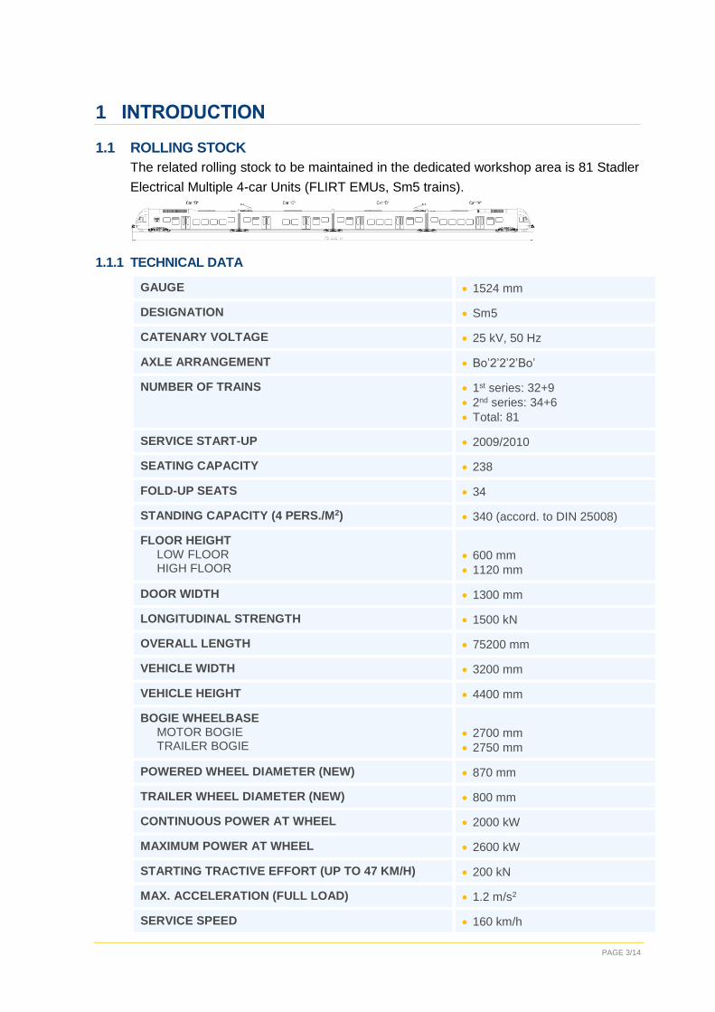
The related rolling stock to be maintained in the dedicated workshop area is 81 Stadler
Electrical Multiple 4-car Units (FLIRT EMUs, Sm5 trains).
1.1.1 TECHNICAL DATA
GAUGE 1524 mm
DESIGNATION Sm5
CATENARY VOLTAGE 25 kV, 50 Hz
AXLE ARRANGEMENT Bo’2’2’2’Bo’
NUMBER OF TRAINS 1st series: 32+9
2nd series: 34+6
Total: 81
SERVICE START-UP 2009/2010
SEATING CAPACITY 238
FOLD-UP SEATS 34
STANDING CAPACITY (4 PERS./M2) 340 (accord. to DIN 25008)
FLOOR HEIGHT LOW FLOOR HIGH FLOOR
600 mm
1120 mm
DOOR WIDTH 1300 mm
LONGITUDINAL STRENGTH 1500 kN
OVERALL LENGTH 75200 mm
VEHICLE WIDTH 3200 mm
VEHICLE HEIGHT 4400 mm
BOGIE WHEELBASE MOTOR BOGIE TRAILER BOGIE
2700 mm
2750 mm
POWERED WHEEL DIAMETER (NEW) 870 mm
TRAILER WHEEL DIAMETER (NEW) 800 mm
CONTINUOUS POWER AT WHEEL 2000 kW
MAXIMUM POWER AT WHEEL 2600 kW
STARTING TRACTIVE EFFORT (UP TO 47 KM/H) 200 kN
MAX. ACCELERATION (FULL LOAD) 1.2 m/s2
SERVICE SPEED 160 km/h

PAGE 4/14
2 SITE DESCRIPTION
2.1 LOCATION IN HELSINKI
Ilmala Depot is located approx. 4.5 km north of Helsinki main station.
2.2 ILMALA DEPOT
The Ilmala Depot is currently managed and operated by the VR Group. A dedicated area
of 4 tracks (8 stands, marked yellow) will be used in the future for independent mainte-
nance of the Sm5 fleet.
2.3 MAINTENANCE TRACKS / STANDS
The current area dedicated for Sm5 maintenance already consists of four PM/CM stands
on tracks 764 and 765, which will not need to be refurbished. Track 763 houses an
existing lifting stand in south end and an overhaul stand in north end. Currently track
762 is mainly used for other than Sm5 trains. This is the area where most of refurbish-
ments can take place. Offices, Workshops and Storage can be built in this area.

PAGE 5/14
3 ALTERNATIVE LAYOUT SOLUTIONS FOR THE NEEDED FACILITIES
Sm5 hall is used currently only for maintenance activities. All other facilities (offices,
storage, showers) are located in other parts of depot. In the new maintenance concept
those facilities have to be separated from VR facilities. This document presents three
alternative options to arrange new facilities.
3.1 OPTION 1 – NEW BUILDING TO THE SOUTH SIDE OF OLD DEPOT (TRACK 762)
New facilities will be located partly in the old Sm5 hall and partly in a new building. The
new building will be built on top of track 762, about five to 10 meters from the south side
of old depot building. (Appendix 1 - Floor plan of option 1)
3.1.1 MAIN CHALLENGE
The main challenge is that the external interfaces for major logistic processes are all
concentrated to the north end of the hall. Material will be delivered from the north end
meaning all bogies and big parts are introduced to the depot from one side. The main
(heavy) crane is also located at the north end of the hall.
The challenge is to develop a concept where all these processes do not interrupt each
other.
APPROACH
The approach taken for this option is to move areas which do not require heavy logistics
as far to the south as possible whilst keeping the north end of the hall as open as pos-
sible to keep open paths to the southern train stands.
3.1.2 NEW BUILDING
To make best use of the no longer required incoming south end of track 762 a lightweight
steel frame building will be installed in this area. The new building would accommodate
offices, mess room, and sanitary rooms. With this solution it is also ensured that the
office building will not block any logistic routes in the main maintenance area.
OFFICES
To save ground floor area it is also possible to use the top of the changing room for
additional offices.
MESS ROOM
The layout allows a mess room (30 m2). The mess room will be equipped with kitchen
furniture and seating for 20-25 employees.
CHANGING ROOMS / SANITARY
An area of approx. 90 m2 can comprise changing rooms, showers and toilets for up to
50 production employees (gender separated).
PAGE 6/14
3.1.3 WORKSHOPS
As modern trains like the Sm5-units do not require extensive mechanical work, a small
workshop (approx. 60m2) is sufficient. The workshop will be divided in a smaller electrical
area and a slightly bigger mechanical area.
The workshops will be accommodated in a semi-permanent, closed room (modular sys-
tem).
3.1.4 STORAGE
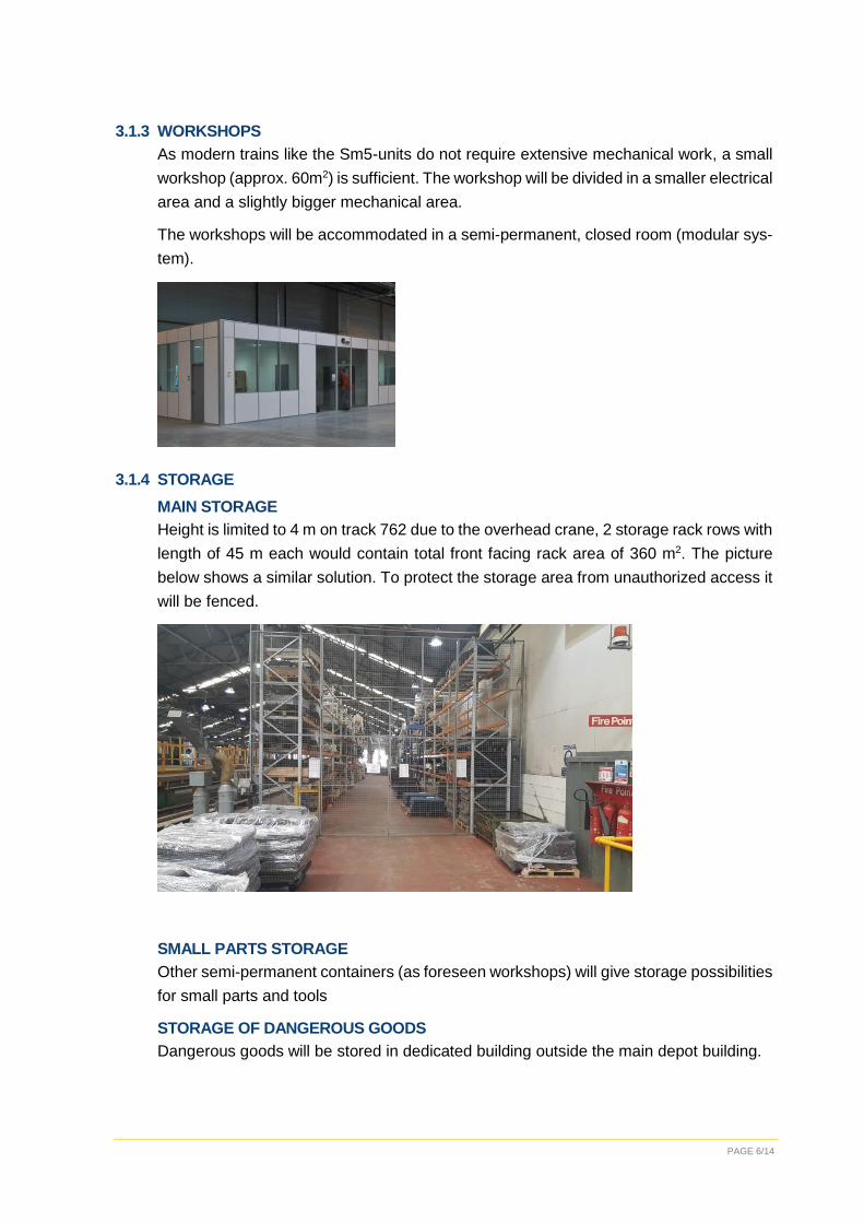
MAIN STORAGE
Height is limited to 4 m on track 762 due to the overhead crane, 2 storage rack rows with
length of 45 m each would contain total front facing rack area of 360 m2. The picture
below shows a similar solution. To protect the storage area from unauthorized access it
will be fenced.
SMALL PARTS STORAGE
Other semi-permanent containers (as foreseen workshops) will give storage possibilities
for small parts and tools
STORAGE OF DANGEROUS GOODS
Dangerous goods will be stored in dedicated building outside the main depot building.

PAGE 7/14
BOGIE STORAGE
An open area between the main storage and the flexible used area will be used for bogie
storage. This location is ideal because it is next to the lifting stand and has direct track
access through the flexible used area. Also, it is still in the reach of 12.5 t crane.
No special installations are required in this area. This enables high flexibility:
When no bogie exchanges are planned bogies for half to a full trainset may be stored
in this area to ensure the availability on short notice. The other bogies shall be stored
externally.
During exchange process the storage area can be used as temporary storage area for
old and new bogies. As there are no buildings and constructions in this area bogies
can easily be lifted between track 762 and 763 as well as over each other.
CAPITAL SPARE PART STORAGE
As the capital spare parts are not planned to be used frequently most capital spare parts
will be stored externally and only a small stack should be available in the depot.
3.1.5 FLEXIBLE USED AREA
To keep open routes from the north end of the hall to the southern train stands no con-
structions will be raised on the complete northern part of track 762 (length approx. 90
m). This area will be dedicated for individual use such as:
Storage along the depot wall
Temporary work stations
Bogie Storage
Additional stand place
o This might be forbidden by safety officials since there are offices located on the
same track.
Logistic routes

PAGE 8/14
3.2 OPTION 2 – ALL FACILITIES INSIDE OF THE OLD SM5 HALL
All facilities will be located in the old Sm5 hall. (Appendix 2 - Floor plan of option 2)
3.2.1 DIFFERENCES TO OPTION 1
In this option, all main requirements to the new structures remain the same as in option
1. The differences are explained in this chapter.
OFFICES
The offices are located at the south end of track 762. To allow best use of the given
space, and because the 12.5 t crane does not reach into this area, the office building
shall be a double story building. For an inside office it is recommended to build it as a
semi-permanent modular solution (as the workshop and small part storage of the main
proposal).
MESS ROOMS / CHANGING ROOMS / TOILETS
To include the mess room, changing rooms and toilets to the main depot building they
would be located just north of the offices.
STORAGE AREA
Compared to option 1 the storage area will move further north on track 762. This will
limit the working area of the 12.5 t crane.
FLEXIBLE USED AREA
As the offices and sanitary rooms are included in the main building the flexible used area
would be reduced to approx. 60 m. Due to that, it is no longer possible to use the northern
stand on track 762 to bring in a complete Sm5 unit.
BOGIE STORAGE
As there is anyways no possibility to bring in a trainset to the flexible used area, bogies
can be stored in that area (now). Another solution would be to disconnect the outside
part of track 762 from track 763 and extend the roof of track 762 to the north in order to
place the bogie storage outside the main depot shed.
OPTION OF SWAPPING THE LIFTING STAND AND THE OVERHAUL STAND
Having the lifting stand in the south (as it is now) and the northern overhaul stand occu-
pied, there is no chance to move a bogie from the lifting stand to the flexible used area
or bogie storage, because the fences of the storage area are blocking crane movements.
In this way it is only possible to exchange bogies when the overhaul stand is not in use.

PAGE 9/14
When swapping the lifting and overhaul stand bogie handling would be much more con-
venient during the exchange process. The downside of the swap would be that the over-
haul stand will no longer be in the reach of the crane. This means that an overhaul task
which requires a crane can no longer be planned on the overhaul stand. Also the adja-
cent office building would block logistic processes of the overhaul stand.
Considering these facts and to save the additional costs of relocating the lifting jacks it
is better to schedule bogie changes for such period when overhaul stand is not occupied.
3.3 OPTION 3 – USE OF THE OLD OFFICE AND LOCKER ROOM FACILITIES
Storage and possibly some workshops/supervisor offices will be located in the old Sm5
hall and other facilities will be located in other parts of depot. (Appendix 3 - Floor plan of
option 3)
3.3.1 DIFFERENCES TO OPTION 1 AND 2
In this option existing office and locker rooms will be used. Distance from Sm5 hall to
these facilities is longer and some of the facilities might be shared with other companies.
In this option there is one more PM/CM stand than in option 2 (and maybe in option 1)
because there is no need to build offices to the south side of track 762. Small supervisor
office can probably be located somewhere else.
PAGE 10/14
4 TRAIN CLEANING
4.1 SITUATION
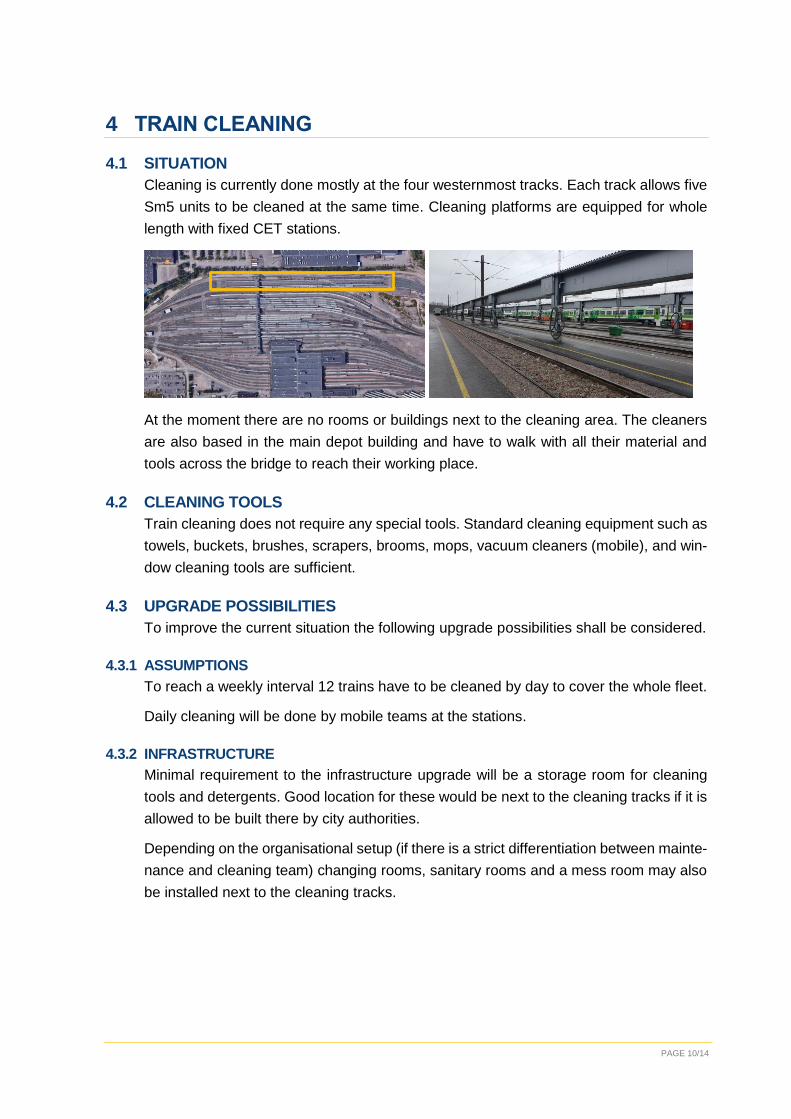
Cleaning is currently done mostly at the four westernmost tracks. Each track allows five
Sm5 units to be cleaned at the same time. Cleaning platforms are equipped for whole
length with fixed CET stations.
At the moment there are no rooms or buildings next to the cleaning area. The cleaners
are also based in the main depot building and have to walk with all their material and
tools across the bridge to reach their working place.
4.2 CLEANING TOOLS
Train cleaning does not require any special tools. Standard cleaning equipment such as
towels, buckets, brushes, scrapers, brooms, mops, vacuum cleaners (mobile), and win-
dow cleaning tools are sufficient.
4.3 UPGRADE POSSIBILITIES
To improve the current situation the following upgrade possibilities shall be considered.
4.3.1 ASSUMPTIONS
To reach a weekly interval 12 trains have to be cleaned by day to cover the whole fleet.
Daily cleaning will be done by mobile teams at the stations.
4.3.2 INFRASTRUCTURE
Minimal requirement to the infrastructure upgrade will be a storage room for cleaning
tools and detergents. Good location for these would be next to the cleaning tracks if it is
allowed to be built there by city authorities.
Depending on the organisational setup (if there is a strict differentiation between mainte-
nance and cleaning team) changing rooms, sanitary rooms and a mess room may also
be installed next to the cleaning tracks.

PAGE 11/14
Requirements:
Room Description
Storage room Separated for tools and detergents
Acid proof floor coating
Power and Water supply
Small workstation
Changing rooms Gender separated
Including showers and toilets
Mess Room Including kitchen furniture
4.4 TRAIN ACCESS
There is level access on the 4 eastern tracks to make it easy for cleaning personnel to
get inside the trains.


