js/jt series thyristor regulators - … · jt (three • types 10a modulation type and 20a •...
TRANSCRIPT

• Types 10A and 20A • Types 30A,
50A and 75A • Types 100A, 150A,
200A and 250A
• Types 10A and 20A
Single-phase thylistor regulation
Three-phase thylistor regulation
• Types 300A, 400A and 500A • Types 1 50A, 200A and 250A
PSE-235B
• Types 300A, 400A and 500A
• Types 30A and 50A • Types 75A and 100A
JS/JT SERIES
THYRISTOR REGULATORS
MODELS JS (SINGLE-PHASE THYRISTOR REGULATORS) JT (THREE-PHASE THYRISTOR REGULATORS)
< FEATURES • Compact and lightweight
The compact and lightweight designs of the thyristor regulators facilitate their mounting and wiring.
• Suited for high-density Instrumentation All types of i -Series thyristor regulators have a slim construction to allow high-density mounting in an instrumentation panel. The 30∼250A (130∼200A: Three-phase type) types, in particular, are ideal for high-density instrumentation, since the mounting pitches have been unified into 300mm to allow multiple -unit mount in one panel.
• A wide selection of current ratings Fourteen types of current ratings, ranging from 10A to 1000A, are available to suit the particular load requirements.
• Optimal model selection according to the characteristics of the heating element To ensure enhanced input and output characteristics, partial feedback of outputs (voltage, current, or power) is provided with the phase control system. The optimal thyristor regulators can be selected according to the particular characteristics of the heating element (nichrome wire, silicone carbide, or other materials).
1
The J -Series thyristor regulators are designed for single - phase and three- phase load applications, and each of the units has a built- in firing unit. Since the thyristor regulators feature compactness and lig htweight, high density of mounting in an instrumentation panel is possible. The control systems available in the thyristor regulators are three kinds of phase control system, frequency division control system by zero-cross switching and ∆Σmodulation type frequency division control system by zero-cross switching (for single - phase loads only). The thyristor regulators based on the phase control system are available with voltage feedback, current feedback, or power feedback, or without feedback, so that an ideal thyristor regulator can be selected according to the particular characteristics of the heating element in an electric furnace. Also, connection of options (setting units) to the thyristor regulators allows gradient setting of outputs, elevation settin g for the minimum output voltage, and other setting operations. Various options including a gradient setting function, an auto -manual mode selector switch, and an output indicating meter are available. The input signals are current signals of 4 to 20mADC or 1 to 5mADC and ON-OFF contact signals.
•Various types of protection functions A thyristor gate turn-off circuit for over-current protection, a fuse unit that rapidly blows out in the event of short circuit, and various other circuit protectors are provided as standard.
•A wide variety of accessories The optimum control system can be built by combining various types of accessories including a gradient setting unit, an upper -limit setting unit, a lower-limit setting unit, a manual setting unit and an elevation setting unit.
•New frequency division control system (For single -phase loads only) On Model JS, the new frequency control system with A modulation is available for sensitive power control. It can be used under high frequency regulation by zero-crossing switching.
•A terminal board cover for preventing an electrical shock is provided as an option.

2
< MODELS
Jo-o o o o o o
PHASE S: Single-phase
T: Three-phase
SUPPLY VOLTAGE 1: 100V/110V/120VAC
2: 200V/220V/240VAC 4: 400V/380V/441VAC
(Specify the voltage)
CURRENT RATING 010: 10A 020: 20A 030: 30A
050: 50A 075: 75A 100: 100A 150: 150A 200: 200A 250: 250A 300: 300A 400: 400A 500: 500A 750: 750A X00: 1000A
CONTROL METHOD/FEEDBACK TYPE
V: Phase control/Voltage feedback A: Phase control/Current feedback W: Phase control/Power feedback N: Phase control/No feedback Z: Frequency division control C: ∆Σmodulation type frequency division control (Single-phase load only)
N : Without feedback
RAPID FUSE (OPTION) A: With rapid fuse (10A or 20A fuses must
be ordered separately.) Blank: Without rapid fuse
< GENERAL SPECIFICA11ONS VOLTAGE RATING:
100/110/120VAC, 200/220/240VAC, or 380/400/440VAC FREQUENCY: 50/60Hz (terminal-selectable) CURRENT RATING:
10A, 20A, 30A, 50A, 75A, 100A, 150A, 200A, 250A, 300A, 400A, 500A, 750A or 1000A (all based on an ambient temperature of 50°C)
INPUT SIGNAL: 4 to 20mADC, 1 to 5mADC and ON-OFF contact signals (terminal-selectable)
OUTPUT RANGE:
Phase control system Voltage feedback —0 to 98% (95%) of the voltage rating Current feedback —0 to 100% of the current rating
(However, the maximum output voltage is 98% (95%) of the voltage rating.)
Power feedback — [0 to 98% (95%) of the voltage rating]× [0 to 100% of the current rating]
No-feedback —— 0 to 98% (95%) of the voltage rating Frequency division control system
0 to 100% of the voltage rating Frequency division rate: 1.5 sec. ( ): In case of three-phase
OUTPUT SETTING RANGE: On condition that optional setting units are provided • Current Inputs —Gradient setting
0 to 100% of the output range Elevation setting 0 to 100% of the output range
• ON-OFF contact inputs —Upper-limit setting 0 to 100% of the maximum output Lower-limit setting 0 to 100% of the upper-limit setting
APPLICABLE LOAD: Resistive load or inductive load (transformer primary side control) For frequency division control system, resistive loads only can be used.
ALLOWABLE VOLTAGE FLUCTUATION: (+)10 to (-)15% of the voltage rating
OPERATING TEMPERATURE RANGE: Performance guarantee range 0 to50°C For allowable current corresponding to temperature exceeding 50°C, see the section on ambient temperatures and allowable current. Operation guarantee temperature (-)10 to 55°C
COOLING METHOD: Current rating of 150A (75A) or less: Self-cooling Current rating of 200A (100A) or more: Cooling fan is provided as standard. ( ): In case of three-phase
OVERCURRENT PROTECTION: Alarm: Over current alarm (with current transformer for current
detector [separate purchase is requested] Rapid fuse molt (more than 30A) Cooling fan abnormal (more than 200A)...
Contact output and lamp display Load short alarm... Lamp display (New frequency division control system only) (10A and 20A no lamp display) Contact capacity... 200 VAC, 0.5A(Resistance load)
INSULATION RESISTANCE: Between power terminals and protective ground terminal 50MΩ at 500VDC
WITHSTAND VOLTAGE: Between power terminals and protective ground terminal 2000VAC, 1 minute (for 100/200V) 2500VAC, 1 minute (for 400V)
INPUT RESISTANCE: 4 to 20mADC — 100Ω or less 1 to 5mADC —— 400Ω or less
2
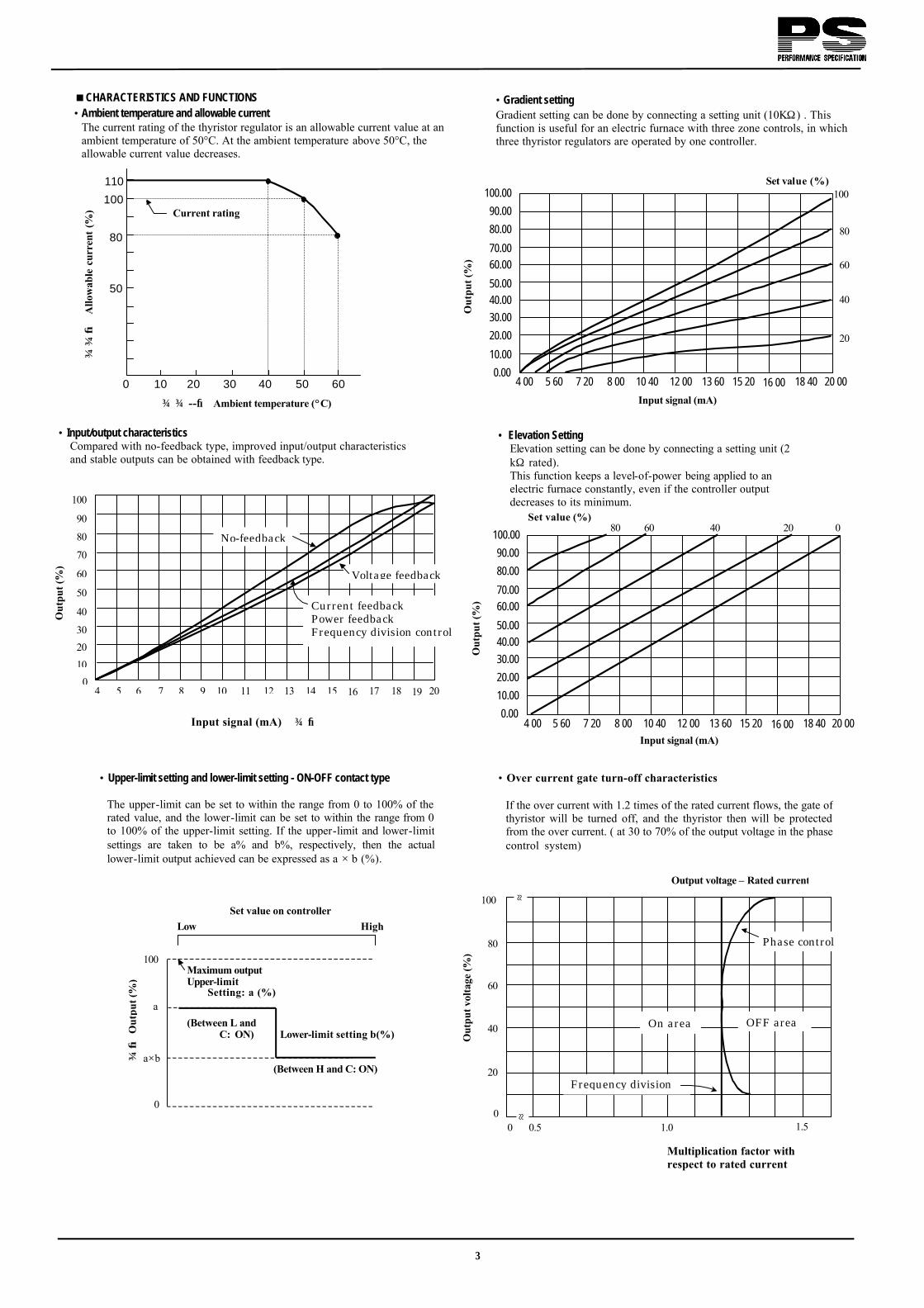
<CHARACTERISTICS AND FUNCTIONS • Ambient temperature and allowable current
The current rating of the thyristor regulator is an allowable current value at an ambient temperature of 50°C. At the ambient temperature above 50°C, the allowable current value decreases.
• Gradient setting Gradient setting can be done by connecting a setting unit (10KΩ) . This function is useful for an electric furnace with three zone controls, in which three thyristor regulators are operated by one controller.
• Input/output characteristics
Compared with no-feedback type, improved input/output characteristics and stable outputs can be obtained with feedback type.
--→ Ambient temperature (°C)
• Elevation Setting Elevation setting can be done by connecting a setting unit (2 kΩ rated). This function keeps a level-of-power being applied to an electric furnace constantly, even if the controller output decreases to its minimum.
Input signal (mA) →
Input signal (mA)
Multiplication factor with respect to rated current
• Upper-limit setting and lower-limit setting - ON-OFF contact type The upper-limit can be set to within the range from 0 to 100% of the rated value, and the lower-limit can be set to within the range from 0 to 100% of the upper-limit setting. If the upper-limit and lower-limit settings are taken to be a% and b%, respectively, then the actuallower-limit output achieved can be expressed as a × b (%).
• Over current gate turn-off characteristics If the over current with 1.2 times of the rated current flows, the gate of thyristor will be turned off, and the thyristor then will be protected from the over current. ( at 30 to 70% of the output voltage in the phase control system)
3
→ A
llow
able
cur
rent
(%)
50
80
100
110
0 10 20 30 40 50 60
Current rating
Input signal (mA)
100 100.00
90.00
80.00
70.00 60.00
50.00 40.00 30.00
20.00
10.00
0.004.00 5.60 7.20 8.00 10.40 12.00 13.60 15.20 16.00 18.40 20.00
Set value (%)
20
40
60
80
Out
put (
%)
100.00
90.00
80.00
70.00 60.00
50.00 40.00 30.00
20.00
10.00
0.004.00 5.60 7.20 8.00 10.40 12.00 13.60 15.20 16.00 18.40 20.00
Set value (%) 20 40 60 80
Out
put (
%)
0
Out
put (
%)
0 10 20 30
40
50
60
70
80
90
4 5 6 7 8 9 10 11 12 13 14 15 16 17 18 19 20
100
No-feedback
Voltage feedback
Current feedback Power feedback Frequency division control
→
Out
put (
%)
Maximum output Upper-limit Setting: a (%)
(Between L and C: ON) Lower-limit setting b(%)
(Between H and C: ON)
Low
100
a
a×b
0
High ∇ Set value on controller
0
20
40
60
80
100
0 0.5 1.0 1.5
≈ ≈
Output voltage – Rated current
Phase control
OFF area On area
Out
put v
olta
ge (%
)
Frequency division

< ACCESSORIES The following accessories are available: • Setting units
Both the VL-JAL and the VL-JMH consist of a variable resistor, a scale plate, and a setting knob.
• VL-JAL, VL-JMH
• VLJHL
• VLU-JAMo
CURRENT RATING 1: 100VAC line (Single-phase only) 2: 200VAC line 4: 400VAC line
(Z: For frequency division control system)
Mounting fixture Output indicator
Gradient setting knob Auto/manual mode selector switch
Manual setting knob
For a power feedback or a current feedback type unit, a current transformer is required for load current and over current detection. On the three-phase thyristor regulator, two current transformers are required.
Model Current rating Coil CTJ010A 10A 10 CTJ020A 20A 5 CTJ030A 30A 5 CTJ050A 50A 2 CTJ075A 75A 2 CTJ100A 100A 1 CTJ150A 150A 1 CTJ200A 200A 1 CTJ300A 300A 1 CTJ400A 400A 1 CTJ500A 500A 1
CTJ750A* 750A 1 CTJX00A* 1000A 1
When models marked with an asterisk (*) is used, a CTJ005A is required.
• 10 to 300A • 400A, 500A
Model Applications Specifications
VI-JAL Gradient setting or lower-limit setting Variable resistance of 10kΩ
VL-JM H Manual setting , upper-limit setting or elevation setting Variable resistance of 2kΩ
VL-JHL Upper-limit setting and lower 1imit setting
Variable resistance of 2kΩ and 10kΩ
VL-JAM
Gradient/manual setting. output indicating meter and auto-manual mode selector switch provided.
1:Voltage indicator 0 to 150V (Sing1e-phase only)
2:Voltage indicator 0 to 250V 3:Voltage indicator 0 to 500V 4: Output setting range 0 to
100% (Frequency division control system only) (Variable resistance 2kΩ , 10kΩ)
• Current transformers
MODEL H G V C1J750A 61 121 55 CTJX00A 73 153 78
4
Upper -limit setting knob 4 - φ4 ( Mounting hole )
Lower-limit setting knob
M4 pan-head screw • 750A, 1000A
Unit: mm

12
• Fuse Units
Model Current rating FU-J010£ 10A FU-J020£ 20A
Blank : Single-phase loads T : Three-phase loads
Single-phase loads Three-phase loads
5
Unit: mm

g INPUT SETTING CIRCUITS
Controller Controller
Selling terminals Selling terminals Selling terminals
Selling terminals
4 to 20mA Short circuit 1 to 5mA Open circuit
Controller Controller Controller
4 to 20mA Short circuit 1 to 5mA Open circuit
4 to 20mA short circuit 1 to 5mA open circuit
3
2 KΩ 2
1
1 2
10 KΩ
3
4 to 20mA Short circuit 1 to 5mA Open circuit
4 to 20mA Short circuit 1 to 5mA Open circuit
Selling terminals
Elevation selling unit Manual selling unit
Auto -manual mode Selector switch
• Current input With manual setting unit and auto-manual mode selector switch
= Current input With elevation setting unit
=Current input 4 to 20mADC or 1 to 5mADC
= Current input With gradient setting unit
• Current input With gradient setting unit and elevation setting unit
1
2
3
4
5
6
7
8
9
10
11
12
13
14
15
16
17
18
19
20
1
2
3
4
5
6
7
8
9
10
11
12
13
14
15
16
17
18
19
20
Gradient selling unit
1
2
3
4
5
6
7
8
9
10
11
12
13
14
15
16
17
18
19
20
2kΩ
3
2
2 1
3 10kΩ
1
2
3
4
5
6
7
8
9
10
11
12
13
14
15
16
17
18
19
20
2 2kΩ
1
3
1
2
3
4
5
6
7
8
9
10
11
12
13
14
15
16
17
18
19
20
6
Gradient setting unit
Elevation setting unit
Gradient selling unit
Auto-manual Mode selector switch
Auto-manual Mode selector switch
4 to 20mA short circuit 1 to 5mA open circuit
4 to 20mA short circuit 1 to 5mA open circuit
4 to 20mA short circuit 1 to 5mA open circuit
Selling terminals
Selling terminals Selling terminals Selling terminals
Selling terminals Selling terminals
Controller Controller
1
2
3
4
5
6
7
8
9
10
11
12
13
14
15
16
17
18
19
20
• ON-OFF contact input With upper-limit setting unit
1
2
3
4
5
6
7
8
9
10
11
12
13
14
15
16
17
18
19
20
2 2kΩ
1
3
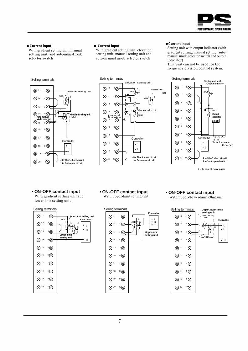
=Current input Setting unit with output indicator (with gradient setting, manual setting, auto-manual mode selector switch and output indic ator) This unit can not be used for the frequency division control system.
=Current input With gradient setting unit, manual setting unit, and auto-manual mode selector switch
= Current input With gradient setting unit, elevation setting unit, manual setting unit and auto-manual mode selector switch
• ON-OFF contact input With gradient setting unit and lower-limit setting unit
1
2
3
4
5
6
7
8
9
10
11
12
13
14
15
16
17
18
19
20
2
2kΩ
1
3
7
1
2
3
4
5
6
7
8
9
10
11
12
13
14
15
16
17
18
19
20
2 2kΩ
1
3
10kΩ
1
2
3
1
2
3
4
5
6
7
8
9
10
11
12
13
14
15
16
17
18
19
20
• ON-OFF contact input With upper-/lower-limit setting unit
Manual setting unit 2kΩ
3 1
2
3
4
5
6
7
8
9
10
11
12
13
14
15
16
17
18
19
20
2 2kΩ
1
3
10kΩ
1
2 3
2
Gradient selling unit
Manual selling unit
Elevation setting unit
1
Controller
2kΩ
10kΩ Output indicator
Setting unit with Output indicator
2
4
U2 V1 (V2)
To lord terminals U2 V1 (V2)
↓ ↓
1
7
( ): In case of three-phase
Upper-limit selling unit
2kΩ
1
3
2 L
H
C
10kΩ 3
2
1 Lower-limit setting unit
Controller
Controller
L HC
Upper-limit setting unit
Controller
LH
C
Upper-/lower-limits setting unit
1
3
2 10kΩ
LH
1
2

=Manual setting only
With manual setting unit = Terminals numbered 11 through 20
For frequency selection, alarm output, and current transformer
• Current input With gradient setting unit and elevation setting unit
8
1
2
3
4
5
6
7
8
9
10
11
12
13
14
15
16
17
18
19
20
1
2
3
4
5
6
7
8
9
10
11
12
13
14
15
16
17
18
19
20
4 to 20mA Short circuit
1 to 5mA Open circuit
4 to 20mA Short circuit
1 to 5mA Open circuit
4 to 20mA Short circuit
1 to 5mA Open circuit
Controller
1
2
3
4
5
6
7
8
9
10
11
12
13
14
15
16
17
18
19
20
NO. n
1
2
3
4
5
6
7
8
9
10
11
12
13
14
15
16
17
18
19
20
NO. 2
1
2
3
4
5
6
7
8
9
10
11
12
13
14
15
16
17
18
19
20
12
NO. 1
1
2
3
4
5
6
7
8
9
10
11
12
13
14
15
16
17
18
19
20
2
Manual setting unit 2kΩ
1
3
Setting terminals Setting terminals Setting terminals
Single-phase loads Three-phase loads
* This function is not included with the phase control system without feedback.
* Current transformer for load current protection
* Current transformer for load current protection
* Alarm output contact signal
* Alarm output contact signal
Frequency section 50Hz: Open circuit60Hz: Short circuit
Frequency section 50Hz: Open circuit60Hz: Short circuit
Protective ground Protective ground

g EQUIPMENT CONFIGURATION AND WIRING
Controller
Controller
Single-phase loads
Thyristor regulator Thyristor regulator
Thyristor regulator Thyristor regulator
Selling terminals Selling terminals
Selling terminals Selling terminals
Load terminals
Source Load
Load terminals
Controller Controller (Current output type) (Current output type)
=Phase control system with voltage feedback =Phase control system without feedback
In case an electric furnace heater is a Fe-Cr wire, a Ni-Cr wire or any other heating element which has a small temperature coefficient of its electrical resistance, keeping the heater voltage feedback can detect the heater voltage and feed back its value to ensure linear and stable output to the heater.
200 400 600 800 1000 1200 1400
0
20
40
60
80
100
120
140
Vol
umet
ric
resi
stan
ce r
ate
µΩ
-cm
→
Temperature ° C →
Fe-Cr
Ni-Cr
1
2
3
4
5
6
7
8
9
10
11
12
13
14
15
16
17
18
19
20
1
2
3
4
5
6
7
8
9
10
11
12
13
14
15
16
17
18
19
20
1
2
3
4
5
6
7
8
9
10
11
12
13
14
15
16
17
18
19
20
9
• Current input • Current input
Three-phase loads
• ON-OFF contact input • ON-OFF contact input
L H
CH
L
U1V1W1
U2
V2W2
Source Load
Source
Load
Load
1
2
3
4
5
6
7
8
9
10
11
12
13
14
15
16
17
18
19
20
U1
V1W1
U2
V2
W2Source
∗ ∗ ∗
U1 V1 U2
*
U1 V1 U2
*Rapid fuse (Option) 10A or 20A fuses must be ordered separately.
Upper-/lower-limits Setting unit
Upper-/lower-limits Setting unit
U1 U2 V1 V2 W1 W2
U1 U2 V1 V2 W1 W2

10
=Phase control system without feedback In case an electric furnace heater is a platinum wire, molybdenum wire or any other heating element of which electrical resistance is very low at low temperature and increases its value to 6 to 12 times at high temperature, the heater current will change with temperature, even if the heater voltage is constant. In particular, large current will flow in the heater at low temperature. As the thyristor regulators with current feedback can detect the heater current and feeds back its value, if the maximum output of the thyristor regulator is preadjusted to the maximum rating current of the electric furnace, the current output is in proportion to the input signal, not related to any changes in the heater resistance, and the highly stable control can be provided without the maximum rating value being exceeded.
50 100 1500 2000 2500
140
Vol
umet
ric
resi
stan
ce r
ate
µΩ
-cm
→
Temperature ° C →
1
2
3
4
5
6
7
8
9
10
11
12
13
14
15
16
17
18
19
20
1
2
3
4
5
6
7
8
9
10
11
12
13
14
15
16
17
18
19
20
0
20
40
60
80
100
120 Tantalum
Single-phase loads Three -phase loads
Thyristor regulator Thyristor regulator
U1 V1 U2
Source Load
Setting terminalsK l
Molybdenum
Tantalum
Transformer
Load terminals
* * * *
Controller (Current output type)
Controller (Current output type)
Platinum
CT
U1 U2 V1 V2 W1 W2
U1
W1
V1
Source Transformer
Load
Setting terminals
* Rapid fuse (Option) 10A or 20A fuses must be ordered separately.
l k lk
l
k
k

=Phase control system with power feedback In case an electric furnace heater is a silicone carbide (SiC) based or any other heating element, of which electrical resistance changes by its heating temperature and deteriorates to about 4 times of the initial value on long term use, the heater power changes with temperature and further changes on long term use, even if the heater voltage is kept constant. As the thyristor regulators with power feedback can detect both voltage and current of the heater and feed back its multiplied value, the power output is in proportion to the input signal, not related to any changes in the heater resistance, and any changes of the power due to deterioration of the heater will be compensated automatically.
1
2
3
4
5
6
7
8
9
10
11
12
13
14
15
16
17
18
19
20
1
2
3
4
5
6
7
8
9
10
11
12
13
14
15
16
17
18
19
20
11
500 1000 1500 0
0.1
0.2
0.3
0.4
0.5
0.6
0.7
Vol
umet
ric
resi
stan
ce r
ate
µΩ
-cm
→
Temperature ° C →
Deterioration
Sic
U1 V1 U2U1 U2 V1 V2 W1 W2
* Rapid fuse (Option)
10A or 20A fuses must be ordered separately.
U1
W1
V1
Source
* * *
Source Load
Setting terminals
Single-phase loads Three-phase loads
Thyristor regulator Thyristor regulator
CT
k l
Controller (Current output type)
Controller (Current output type)
Setting terminals Load k l
k l U2
W2
V2
l
k
k
Loadterminals

=Frequency division control system (Zero-cross switching) As the frequency division control system (Zero-cross switching) turns on and off the thyristor near the zero point of the power supply, high-frequency noise is not generated, and the thyristor can be powered from the same power supply as that of digital equipment having low noise immunity. Since this system can change the ON time and OFF time of the power supply within a constant time, it is suited for use in electric furnaces with large heat capacity. ∆Σ modulation type frequency division control system by zero-cross switching (single-phase loads only) is also available for sensitive power control.
1
2
3
4
5
6
7
8
9
10
11
12
13
14
15
16
17
18
19
20
1
2
3
4
5
6
7
8
9
10
11
12
13
14
15
16
17
18
19
20
12
* Rapid fuse (Option) 10A or 20A fuse must be ordered separately.
Controller (Current output type)
Controller (Current output type)
Setting terminals Setting terminals
Source Load
*
Source
Load terminals
U1 V1 U2
U1
V1 W1
U2
V2
W2
Load
* * *
U1 U1 V1 V2 W1 W2
Single-phase loads Three -phase loads
Thyristor regulator Thyristor regulator

11
<OUTSIDE DIMENSIONS (FOR SINGLE-PHASE LOADS)
• Types 10A and 20A • Types 30A, 50A and 75A
• Types 100A, 150A, 200A and 250A • Types 300A, 400A and 500A
Weight: Approx. 1.5kgWeight: Approx. 1.5kg
• Types 750A and 1000A
Weight: Approx. 6kg
Weight: Approx. 11kg
Weight: Approx. 33kg
13
Unit: mm

12
<OUTSIDE DIMENSIONS (FOR SINGLE-PHASE LOADS) (∆ Σ MODULATION TYPE FREQUENCY DIVISION CONTROL SYSTEM ONLY)
• Types 10A and 20A • Types 30A, 50A and 75A
.
14
• Types 100A 150A, 200A and 250A
Weight: Approx. 1.5kg
Weight: Approx. 2.5kg
• Types 300A, 400A and 500A
Weight: Approx. 6kg
Weight: Approx. 11kg
• Types750A and 1000A
Weight: Approx. 33kg Unit: mm

11
<OUTSIDE DIMENSIONS (FOR THREE-PHASE LOADS)
• Types 10A and 20A • Types 30A and 50A
• Types 75A and 100A • Types 150A, 200A and 250A
Weight: Approx. 4kg Weight: Approx. 6.5kg
• Types 300A, 400A and 500A
Weight: Approx. 11kg Weight: Approx. 17kg
Weight: Approx. 33kg
• Types 750A and 1000A
Weight: Approx. 33kg
Unit: mm
M16: For 500A
15

12
32-8, KUMANO-CHO, ITABASHI-KU, TOKYO 173-8632 PHONE: +81-3-3956-2171
FAX: +81-3-3956-0915 E-mail: [email protected]
Website: http://www.chino.co.jp
Specifications subject to change without notice. Original 2002
16