jppcs niagara mohawk power corporation nine mile point
TRANSCRIPT

Mr. John H. Mueller Chief Nuclear Officer Niagara Mohawk Power Corporation Nine Mile Point Nuclear Station Operations Building, Second Floor P.O. Box 63 Lycoming, NY 13093
March 2, 2000
/ I '¾-'
f\JPP�c�S�
SUBJECT: NINE MILE POINT NUCLEAR STATION, UNIT NO. 2 - ISSUANCE OF AMENDMENT RE: OSCILLATION POWER RANGE MONITORING SYSTEM (TAC NO. MA7119)
Dear Mr. Mueller:
The Commission has issued the enclosed Amendment No. 9 2 to Facility Operating License No. NPF-69 for the Nine Mile Point Nuclear Station, Unit No. 2. The amendment consists of changes to the Technical Specifications (TS) in response to your application transmitted by letter dated October 25, 1999, and supplemented by letters dated February 2 and 7, 2000.
The amended TS permit use of the already-installed Oscillation Power Range Monitor system. We issued amended pages both to the previous TS and to the recently issued Improved TS (ITS, Amendment No. 91). As stated in the transmittal letter for Amendment No. 91, the preAmendment-No. 91 TS is still in effect until ITS is implemented.
A copy of the related Safety Evaluation is enclosed. A Notice of Issuance will be included in the Commission's biweekly Federal Register Notice.
Sincerely,
Peter S'i.a'/1m, Senior Project Manager, Section 1 Project Directorate I Division of Licensing Project Management Office of Nuclear Reactor Regulation
Docket No. 50-410
Enclosures: 1. Amendment No. 92 to NPF-69 2. Safety Evaluation
cc w/encls: See next page DISTRIBUTION: File Center PUBLIC E. Adensam (e-mail) M. Gamberoni (A) S. Little
OGC G. Hill (2) W. Beckner M. Mitchell R. Tjader
ACRS M. Oprendek, RGN-I
DOCUMENT NAME: G:\PDI-1\NMP2\AMDA7119.WPD
To receive a copy of this document, indicate in the box: "C" = Copy without attachment/enclosure "E" = Copy with attachment/enclosure "N" = No copy ,
OFFICE PDI/PM " E PDI/LA ^ýý. I OGC" PDI/f CI EICB/E NAME PTam.:Lcc •. • SListteý ''I• ' (vVi 0A. IMGambio-'h EMarinos. ,Y"
DATE Record Copy 1 - 12- E Official Record Copy '

UNITED STATES NUCLEAR REGULATORY COMMISSION
WASHINGTON, D.C. 20555-0001
March 2, 2000
Mr. John H. Mueller Chief Nuclear Officer Niagara Mohawk Power Corporation Nine Mile Point Nuclear Station Operations Building, Second Floor P.O. Box 63 Lycoming, NY 13093
SUBJECT: NINE MILE POINT NUCLEAR STATION, UNIT NO. 2 - ISSUANCE OF AMENDMENT RE: OSCILLATION POWER RANGE MONITORING SYSTEM (TAC NO. MA7119)
Dear Mr. Mueller:
The Commission has issued the enclosed Amendment No. 92 to Fqicility Operating License No. NPF-69 for the Nine Mile Point Nuclear Station, Unit No. 2. The amendment consists of changes to the Technical Specifications (TS) in response to your application transmitted by letter dated October 25, 1999, and supplemented by letters dated February 2 and 7, 2000.
The amended TS permit use of the already-installed Oscillation Power Range Monitor system. We issued amended pages both to the previous TS and to the recently issued Improved TS (ITS, Amendment No. 91). As stated in the transmittal letter for Amendment No. 91, the preAmendment-No. 91 TS is still in effect until ITS is implemented.
A copy of the related Safety Evaluation is enclosed. A Notice of Issuance will be included in the Commission's biweekly Federal Register Notice.
Sincerely,
Peter S. Tam, Senior Project Manager, Section 1 Project Directorate I Division of Licensing Project Management Office of Nuclear Reactor Regulation
Docket No. 50-410
Enclosures: 1. Amendment No. 92 to NPF-69 2. Safety Evaluation
cc w/encls: See next page
Nine Mile Nuclear Station Unit No. 2
Regional Administrator, Region I U. S. Nuclear Regulatory Commission 475 Allendale Road King of Prussia, PA 19406
Resident Inspector Nine Mile Point Nuclear Station P.O. Box 126 Lycoming, NY 13093
Mr. Jim Rettberg NY State Electric & Gas Corporation Corporate Drive Kirkwood Industrial Park P.O. Box 5224 Binghamton, NY 13902-5224
Mr. John V. Vinquist, MATS Inc. P.O. Box 63 Lycoming, NY 13093
Supervisor Town of Scriba Route 8, Box 382 Oswego, NY 13126
Mr. Richard Goldsmith Syracuse University College of Law E.I. White Hall Campus Syracuse, NY 12223
Charles Donaldson, Esquire Assistant Attorney General New York Department of Law 120 Broadway New York, NY 10271
Mr. Timothy S. Carey Chair and Executive Director State Consumer Protection Board 5 Empire State Plaza, Suite 2101 Albany, NY 12223
Mark J. Wetterhahn, Esquire Winston & Strawn 1400 L Street, NW. Washington, DC 20005-3502
Gary D. Wilson, Esquire Niagara Mohawk Power Corporation 300 Erie Boulevard West Syracuse, NY 13202
Mr. F. William Valentino, President New York State Energy, Research, and Development Authority
Corporate Plaza West 286 Washington Avenue Extension Albany, NY 12203-6399
-
" NUCEA UNITED STATES *NUCLEAR REGULATORY COMMISSION * WASHINGTON, D.C. 20555-0001
NIAGARA MOHAWK POWER CORPORATION
DOCKET NO. 50-410
NINE MILE POINT NUCLEAR STATION, UNIT 2
AMENDMENT TO FACILITY OPERATING LICENSE
Amendment No. 92 License No. NPF-69
1. The Nuclear Regulatory Commission (the Commission) has found that:
A. The application for amendment by Niagara Mohawk Power Corporation (the licensee) dated October 25, 1999, as supplemented by letters dated Iebruary 2 and 7, 2000, complies with the standards and requirements of the Atomic Energy Act of 1954, as amended (the Act) and the Commission's rules and regulations set forth in 10 CFR Chapter 1;
B. The facility will operate in conformity with the application, the provisions of the Act, and the rules and regulations of the Commission;
C. There is reasonable assurance (i) that the activities authorized by this amendment can be conducted without endangering the health and safety of the public, and (ii) that such activities will be conducted in compliance with the Commission's regulations;
D. The issuance of this amendment will not be inimical to the common defense and security or to the health and safety of the public; and
E. The issuance of this amendment is in accordance with 10 CFR Part 51 of the Commission's regulations and all applicable requirements have been satisfied.
2. Accordingly, the license is amended by changes to the Technical Specifications as indicated in the attachment to this license amendment, and paragraph 2.C.(2) of Facility Operating License No. NPF-69 is hereby amended to read as follows:
-2-
(2) Technical Specifications and Environmental Protection Plan
The Technical Specifications contained in Appendix A and the Environmental Protection Plan contained in Appendix B, both of which are attached hereto, as revised through Amendment No. 92 are hereby incorporated into this license. Niagara Mohawk Power Corporation shall operate the facility in accordance with the Technical Specifications and the Environmental Protection Plan.
3. This license amendment is effective as of the date of its issuance to be implemented before activation of the Oscillation Power Range Monitor System, but no later than August 31, 2000.
FOR THE NUCLEAR REGULATORY COMMISSION
Marsha Gamberoni, Acting Chief, Section 1 Project Directorate I Division of Licensing Project Management Office of Nuclear Reactor Regulation
Attachment: Changes to the Technical
Specifications
Date of Issuance: March 2, 2000
ATTACHMENT TO LICENSE AMENDMENT NO. 92
TO FACILITY OPERATING LICENSE NO. NPF-69
DOCKET NO. 50-410
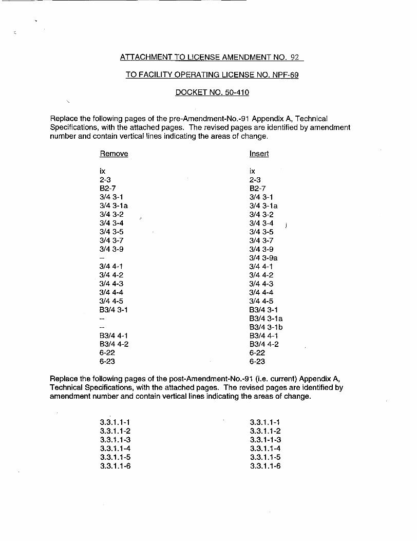
Replace the following pages of the pre-Amendment-No.-91 Appendix A, Technical Specifications, with the attached pages. The revised pages are identified by amendment number and contain vertical lines indicating the areas of change.
Remove
ix 2-3 B2-7 3/4 3-1 3/4 3-1 a 3/4 3-2 3/4 3-4 3/4 3-5 3/4 3-7 3/4 3-9
3/44-1 3/4 4-2 3/4 4-3 3/4 4-4 3/4 4-5 B3/4 3-1
B3/4 4-1 B3/4 4-2 6-22 6-23
Insert
ix 2-3 B2-7 3/4 3-1 3/4 3-1a 3/4 3-2 3/4 3-4 3/4 3-5 3/4 3-7 3/4 3-9 3/4 3-9a 3/4 4-1 3/4 4-2 3/4 4-3 3/4 4-4 3/4 4-5 B3/4 3-1 B3/4 3-1 a B3/4 3-1 b B3/4 4-1 B3/4 4-2 6-22 6-23
Replace the following pages of the post-Amendment-No.-91 (i.e. current) Appendix A, Technical Specifications, with the attached pages. The revised pages are identified by amendment number and contain vertical lines indicating the areas of change.
3.3.1.1-1 3.3.1.1-2 3.3.1.1-3 3.3.1.1-4 3.3.1.1-5 3.3.1.1-6
3.3.1.1-1 3.3.1.1-2 3.3.1-1-3 3.3.1.1-4 3.3.1.1-5 3.3.1.1-6
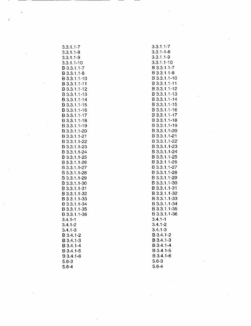
3.3.1.1-7 3.3.1.1-8 3.3.1.1-9 3.3.1.1-10 B 3.3.1.1-7 B 3.3.1.1-8 B 3.3.1.1-10 B 3.3.1.1-11 B 3.3.1.1-12 B 3.3.1.1-13 B 3.3.1.1-14 B 3.3.1.1-15 B 3.3.1.1-16 B 3.3.1.1-17 B 3.3.1.1-18 B 3.3.1.1-19 B 3.3.1.1-20 B 3.3.1.1-21 B 3.3.1.1-22 B 3.3.1.1-23 B 3.3.1.1-24 B 3.3.1.1-25 B 3.3.1.1-26 B 3.3.1.1-27 B 3.3.1.1-28 B 3.3.1.1-29 B 3.3.1.1-30 B 3.3.1.1-31 B 3.3.1.1-32 B 3.3.1.1-33 B 3.3.1.1-34 B 3.3.1.1-35 B 3.3.1.1-36 3.4.1-1 3.4.1-2 3.4.1-3 B 3.4.1-2 B 3.4.1-3 B 3.4.1-4 B 3.4.1-5 B 3.4.1-6 5.6-3 5.6-4
3.3.1.1-7 3.3.1-1-8 3.3.1.1-9 3.3.1.1-10 B 3.3.1.1-7 B 3.3.1.1-8 B 3.3.1 1-10 B 3.3.1 1-11 B 3.3.1.1-12 B 3.3.1.1-13 B 3.3.1.1-14 B 3.3.1.1-15 B 3.3.1.1-16 B 3.3.1.1-17 B 3.3.1.1-18 B 3.3.1.1-19 B 3.3.1.1-20 B 3.3.1.1-j21 B 3.3.1.1-22 B 3.3.1.1-23 B 3.3.1.1-24 B 3.3.1.1-25 B 3.3.1.1-26 B 3.3.1.1-27 B 3.3.1.1-28 B 3.3.1.1-29 B 3.3.1.1-30 B 3.3.1.1-31 B 3.3.1.1-32 B 3.3.1.1-33 B 3.3.1.1-34 B 3.3.1.1-35 B 3.3.1.1-36 3.4.1-1 3.4.1-2 3.4.1-3 B 3.4.1-2 B 3.4.1-3 B 3.4.1-4 B 3.4.1-5 B 3.4.1-6 5.6-3 5.6-4
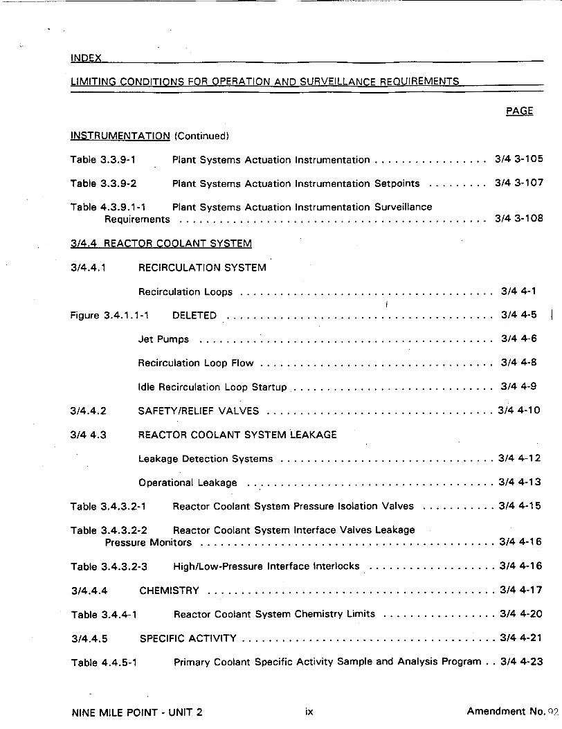
INDEX
LIMITING CONDITIONS FOR OPERATION AND SURVEILLANCE REQUIREMENTS
PAGE
INSTRUMENTATION (Continued)
Table 3.3.9-1 Plant Systems Actuation Instrumentation ........
Table 3.3.9-2 Plant Systems Actuation Instrumentation Setpoints
Table 4.3.9.1-1 Plant Systems Actuation Instrumentation Surveillanc Requirem ents .....................................
3/4.4 REACTOR COOLANT SYSTEM
3/4.4.1 RECIRCULATION SYSTEM
Recirculation Loops ............................
Figure 3.4.1.1-1 DELETED ..............................
Jet Pum ps . ..................................
Recirculation Loop Flow .........................
Idle Recirculation Loop Startup ....................
3/4.4.2 SAFETY/RELIEF VALVES ........................
3/4 4.3 REACTOR COOLANT SYSTEM LEAKAGE
Leakage Detection Systems ......................
Operational Leakage ...........................
Table 3.4.3.2-1 Reactor Coolant System Pressure Isolation Valves
Table 3.4.3.2-2 Reactor Coolant System Interface Valves Leakage Pressure M onitors ....................................
Table 3.4.3.2-3 High/Low-Pressure Interface Interlocks .........
3/4.4.4 CHEM ISTRY .................................
Table 3.4.4-1 Reactor Coolant System Chemistry Limits .......
3/4.4.5 SPECIFIC ACTIVITY ............................
Table 4.4.5-1 Primary Coolant Specific Activity Sample and Analy,
3/4 3-105
3/4 3-107
3/4 3-108e
3/4 4-1
3/4 4-5
3/4 4-6
3/4 4-8
3/4 4-9
3/4 4-10
.......... 3/4 4-12
.......... 3/4 4-13
.......... 3/4 4-15
.......... 3/44-16
.......... 3/44-16
.......... 3/44-17
.......... 3/4 4-20
.......... 3/4 4-21
is Program . . 3/4 4-23
NINE MILE POINT - UNIT 2
I
Sv
ix Amendment No. q2
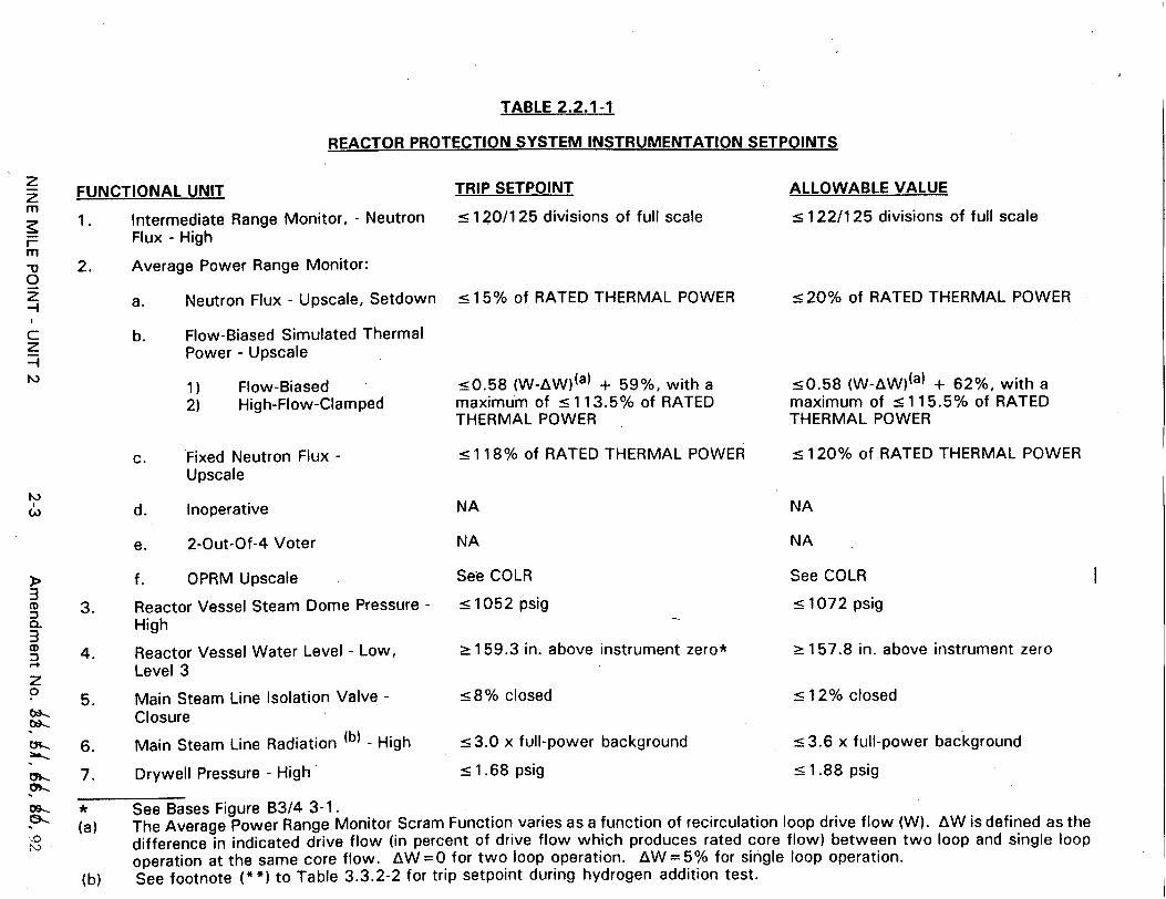
TABLE 2.2.1-1
REACTOR PROTECTION SYSTEM INSTRUMENTATION SETPOINTS
FUNCTIONAL UNIT
1. Intermediate Range Monitor, - Neutron Flux - High
2. Average Power Range Monitor:
a. Neutron Flux - Upscale, Setdown
b. Flow-Biased Simulated Thermal Power - Upscale
1) 2)
Flow-Biased High-Flow-Clamped
c. Fixed Neutron Flux Upscale
d. Inoperative
e. 2-Out-Of-4 Voter
f. OPRM Upscale
3. Reactor Vessel Steam Dome Pressure High
4. Reactor Vessel Water Level - Low, Level 3
5. Main Steam Line Isolation Valve Closure
6. Main Steam Line Radiation (b) - High
7. Drywell Pressure - High
TRIP SETPOINT
< 1 20/125 divisions of full scale
__< 15% of RATED THERMAL POWER
<0.58 (W-AW)(a) + 59%, with a maximum of _ 113.5% of RATED THERMAL POWER
_5118% of RATED THERMAL POWER
NA
NA
See COLR
_5 1052 psig
_ 159.3 in. above instrument zero*
5-8% closed
_<3.0 x full-power background
_<1.68 psig
ALLOWABLE VALUE
_< 122/125 divisions of full scale
<20% of RATED THERMAL POWER
_50.58 (W-AW)(a) + 62%, with a maximum of _5115.5% of RATED THERMAL POWER
-s 120% of RATED THERMAL POWER
NA
NA
See COLR
_< 1072 psig
_> 157.8 in. above instrument zero
_512% closed
_53.6 x full-power background
-< 1.88 psig
* See Bases Figure B3/4 3-1. (a) The Average Power Range Monitor Scram Function varies as a function of recirculation loop drive flow (W). AW is defined as the
difference in indicated drive flow (in percent of drive flow which produces rated core flow) between two loop and single loop operation at the same core flow. AW=O for two loop operation. AW=5% for single loop operation.
(b) See footnote (**) to Table 3.3.2-2 for trip setpoint during hydrogen addition test.
Z m
m "-u 0 z
EI
I
BASES FOR LIMITING SAFETY SYSTEM SETTINGS
REACTOR PROTECTION SYSTEM INSTRUMENTATION SETPOINTS
2.2.1 (Continued)
by a significant amount, the rate of power rise is very slow. Generally, the heat flux is in near equilibrium with the fission rate. In an assumed uniform rod withdrawal approach to the trip level, the rate of power rise is not more than 5% of RATED THERMAL POWER per minute and the APRM system would be more than adequate to assure shutdown before the power could exceed the Safety Limit. The 15% neutron flux trip remains active until the mode switch is placed in the Run position.
The APRM trip system is calibrated using heat balance data taken during steady-state conditions. Fission chambers provide the basic input to the system and, therefore, the monitors respond directly and quickly to changes that result from transient operation for the case of the Fixed Neutron Flux - Upscale setpoint; i.e., for a power increase, the THERMAL POWER of the fuel will be less than that indicated by the neutron flux because of the time constants of the heat transfer associated with the fuel. For the FlowBiased Simulated Thermal Power - Upscale setpoint, a time constant of 6 + 0.6 seconds is introduced into the flow-biased APRM in order to simulate the fuel thermal transient characteristics. A more conservative maximum value is used for the flow-biased setpoint as shown in Table 2.2.1-1.
The APRM setpoints were selected to provide adequate margin for the Safety Limits and yet allow operating margin that reduces the possibility of unnecessary shutdowni The flow referenced Trip Setpoint must be adjusted by the specified formula in Specification 3.2.2 in order to maintain these margins when CMFLPD is greater than or equal to FRTP.
The APRM channels also include an Oscillation Power Range Monitor (OPRM) Upscale Function. The OPRM Upscale Function provides compliance with GDC 10 and GDC 12, thereby providing protection from exceeding the fuel MCPR safety limit (SL) due to anticipated thermal-hydraulic power oscillations. The OPRM Upscale trip setpoint and allowable value are maintained in the Core Operating Limits Report.
3. Reactor Vessel Steam Dome Pressure - Hiqh
High pressure in the nuclear skystem could cause a rupture to the nuclear system process barrier resulting in the release of fission products. A pressure increase during operation will also tend to increase the power of the reactor by compressing voids, thus adding reactivity. The trip will quickly reduce the neutron flux, counteracting the pressure increase. The trip setting is slightly higher than the operating pressure to permit normal operation without spurious trips. The setting provides for a wide margin to the maximum allowable design pressure and takes into account the location of the pressure measurement compared with the highest pressure that occurs in the system during a transient. This Trip Setpoint is effective at low power/flow conditions when the turbine control valve fast closure and turbine stop valve closure trips are bypassed. For load rejection or a turbine trip under these conditions, the transient analysis indicated an adequate margin to the thermal hydraulic limit.
4. Reactor Vessel Water Level - Low
The reactor vessel water level Trip Setpoint was chosen far enough below the normal operating level to avoid spurious trips but high enough above the fuel to assure that there is adequate protection for the fuel and pressure limits.
NINE MILE POINT - UNIT 2 AMENDMENT NO. 92132-7
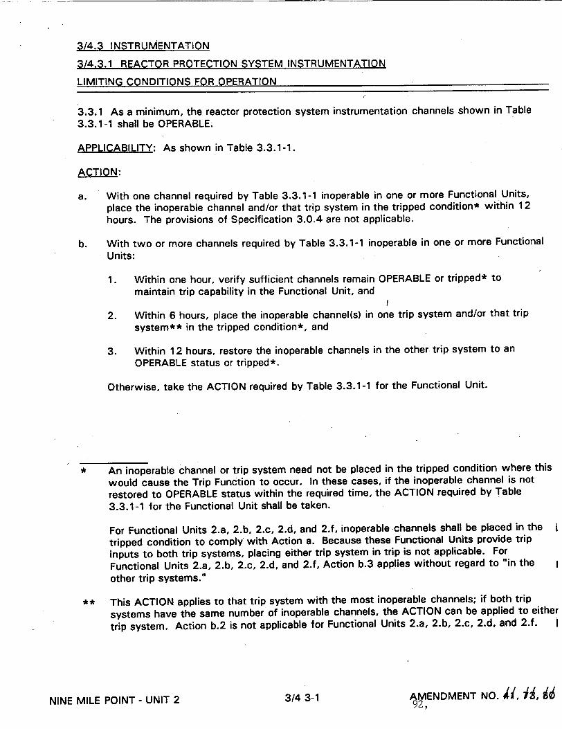
3/4.3 INSTRUMENTATION
3/4.3.1 REACTOR PROTECTION SYSTEM INSTRUMENTATION
LIMITING CONDITIONS FOR OPERATION
3.3.1 As a minimum, the reactor protection system instrumentation channels shown in Table
3.3.1-1 shall be OPERABLE.
APPLICABILITY: As shown in Table 3.3.1-1.
ACTION:
a. With one channel required by Table 3.3.1-1 inoperable in one or more Functional Units, place the inoperable channel and/or that trip system in the tripped condition* within 12 hours. The provisions of Specification 3.0.4 are not applicable.
b. With two or more channels required by Table 3.3.1-1 inoperable in one or more Functional Units:
1. Within one hour, verify sufficient channels remain OPERABLE or tripped* to maintain trip capability in the Functional Unit, and
2. Within 6 hours, place the inoperable channel(s) in one trip system and/or that trip
system** in the tripped condition*, and
3. Within 12 hours, restore the inoperable channels in the other trip system to an OPERABLE status or tripped*.
Otherwise, take the ACTION required by Table 3.3.1-1 for the Functional Unit.
* An inoperable channel or trip system need not be placed in the tripped condition where this
would cause the Trip Function to occur. In these cases, if the inoperable channel is not
restored to OPERABLE status within the required time, the ACTION required by Table
3.3.1-1 for the Functional Unit shall be taken.
For Functional Units 2.a, 2.b, 2.c, 2.d, and 2.f, inoperable channels shall be placed in the I
tripped condition to comply with Action a. Because these Functional Units provide trip
inputs to both trip systems, placing either trip system in trip is not applicable. For
Functional Units 2.a, 2.b, 2.c, 2.d, and 2.f, Action b.3 applies without regard to "in the other trip systems.
** This ACTION applies to that trip system with the most inoperable channels; if both trip
systems have the same number of inoperable channels, the ACTION can be applied to either
trip system. Action b.2 is not applicable for Functional Units 2.a, 2.b, 2.c, 2.d, and 2.f.
NINE MILE POINT- UNIT 2 3/4 3-1 AMENDMENT NO. •(, , 92,
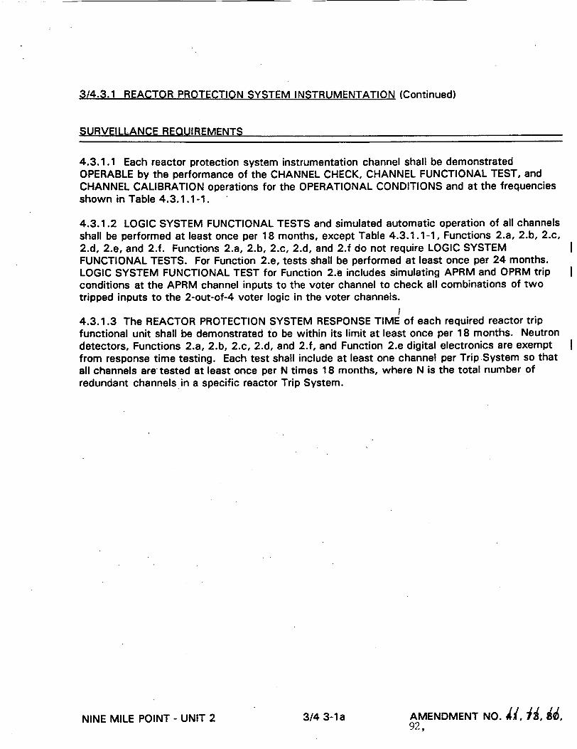
3/4.3.1 REACTOR PROTECTION SYSTEM INSTRUMENTATION (Continued)
SURVEILLANCE REQUIREMENTS
4.3.1.1 Each reactor protection system instrumentation channel shall be demonstrated OPERABLE by the performance of the CHANNEL CHECK, CHANNEL FUNCTIONAL TEST, and CHANNEL CALIBRATION operations for the OPERATIONAL CONDITIONS and at the frequencies shown in Table 4.3.1.1-1.
4.3.1.2 LOGIC SYSTEM FUNCTIONAL TESTS and simulated automatic operation of all channels shall be performed at least once per 18 months, except Table 4.3.1.1-1, Functions 2.a, 2.b, 2.c, 2.d, 2.e, and 2.f. Functions 2.a, 2.b, 2.c, 2.d, and 2.f do not require LOGIC SYSTEM FUNCTIONAL TESTS. For Function 2.e, tests shall be performed at least once per 24 months. LOGIC SYSTEM FUNCTIONAL TEST for Function 2.e includes simulating APRM and OPRM trip conditions at the APRM channel inputs to the voter channel to check all combinations of two tripped inputs to the 2-out-of-4 voter logic in the voter channels.
4.3.1.3 The REACTOR PROTECTION SYSTEM RESPONSE TIME of each required reactor trip functional unit shall be demonstrated to be within its limit at least once per 18 months. Neutron detectors, Functions 2.a, 2.b, 2.c, 2.d, and 2.f, and Function 2.e digital electronics are exempt from response time testing. Each test shall include at least one channel per Trip System so that all channels are tested at least once per N times 18 months, where N is the total number of redundant channels in a specific reactor Trip System.
NINE MILE POINT - UNIT 2 AMENDMENT NO. i, f, •, 92,
3/4 3-1 a

TABLE 3.3.1-1
REACTOR PROTECTION SYSTEM INSTRUMENTATION
FUNCTIONAL UNIT
1. Intermediate Range Monitors:
a. Neutron Flux - High
b. Inoperative
2. Average Power Range Monitor:
a. Neutron Flux - Upscale, Setdown
b. Flow Biased Simulated
Thermal Power - Upscale
c. Fixed Neutron Flux - Upscale
d. Inoperative
e. 2-Out-Of-4 Voter
f. OPRM Upscale
3. Reactor Vessel Steam Dome Pressure - High
4. Reactor.Vessel Water Level Low, Level 3
APPLICABLE OPERATIONAL CONDITIONS
MINIMUM OPERABLE CHANNELS PER TRIP
SYSTEM (a)
I
0 z -n z
3 3 3
3 3 3
3(I) 3(I)
3(0)
3(0)
3(0) 3(0)
2 3,4 5(b)
2 3,4 5
2 5(k)
1
1
1,2 5(k)
1,2 5(k)
1 (m) 3(I)
f, 2(d) 2
1,22 1
2 2
ACTION
M z
m z --i
1 2 3
1 2 3
1 3
4
4
1
3
1 3
10 1
1
I
1, 2

TABLE 3.3.1-1 (Continued)
REACTOR PROTECTION SYSTEM INSTRUMENTATION
TABLE NOTATIONS
(a) A channel may be placed in an inoperable status for up to 6 hours for required surveillance without placing the Trip System in the tripped condition provided at least one OPERABLE channel in the same Trip System is monitoring that parameter.
(b) Unless adequate shutdown margin has been demonstrated per Specification 3.1.1, and the Refuel position one-rod-out interlock is OPERABLE per Specification 3.9.1, the shorting links shall be removed from the RPS circuitry prior to and during the time any control rod is withdrawn.*
(c) Deleted.
(d) This function is not required to be OPERABLE when the reactor pressure vessel head is removed per Specification 3.10.1.
(e) This function shall be automatically bypassed when the reactor mode switch is not in the Run position.
(f) This function is not required to be OPERABLE when PRIMARY CONTAINMENT INTEGRITY is not required.
(g) Also actuates the standby gas treatment system.
(h) With any control rod withdrawn. Not applicable to control rods removed per Specification 3.9.10.1 or 3.9.10.2.
(i) This function shall be automatically bypassed when turbine first stage pressure is less than or equal to 136.4** psig, equivalent, to THERMAL POWER less than 30% of RATED THERMAL POWER.
(j) Also actuates the EOC-RPT system.
(k) Required to be OPERABLE only during shutdown margin demonstrations performed per Specification 3.10.3.
(I) Since each APRM provides inputs to both trip systems, the minimum operable channels specified in Table 3.3.1-1 are the total APRM channels required (i.e., it is not on a trip system basis). The 6 hour allowed test time to complete a channel surveillance test (Note (a) above) is applicable provided at least two OPERABLE channels are monitoring that parameter.
(m) This function shall be automatically enabled when APRM Simulated Thermal Power is >_30% and recirculation drive flow is <60% of rated recirculation drive flow.
* Not required for control rods removed per Specification 3.9.10.1 or 3.9.10.2.
** To allow for instrument accuracy, calibration and drift, a setpoint of less than or equal to 125.8 psig turbine first stage pressure shall be used.
NINE MILE POINT - UNIT 2 3/4 3-4 AMENDMENT NO. 4, 1, i1, I$ 92,
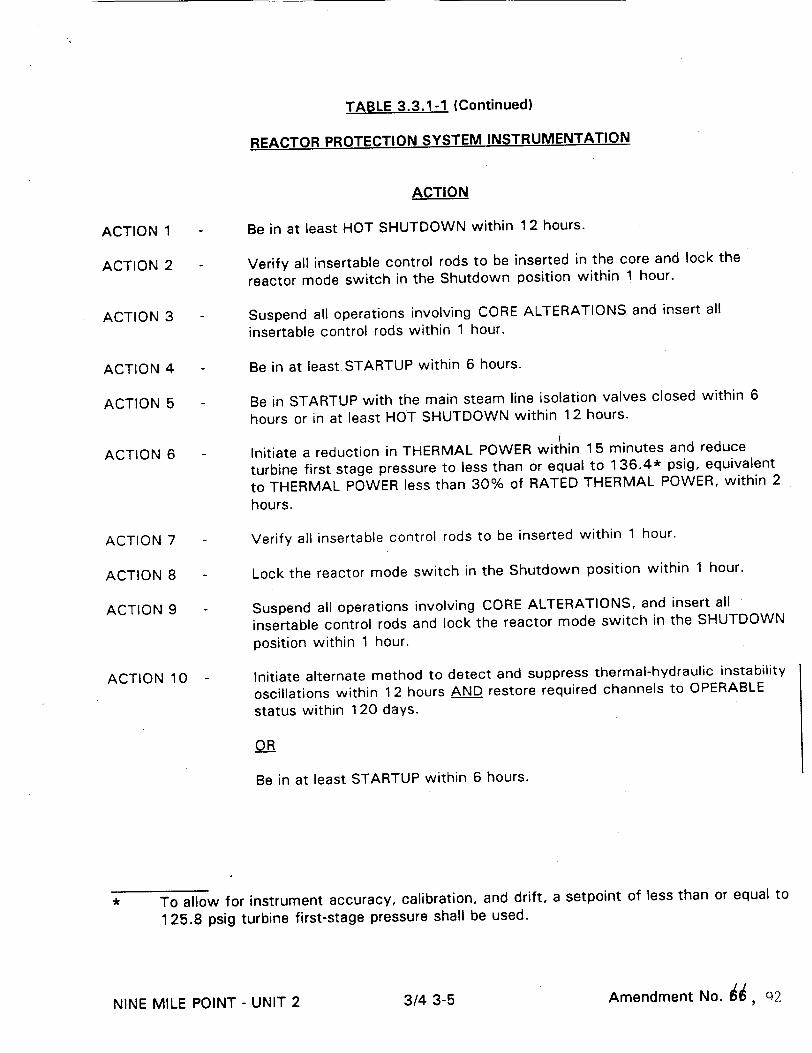
TABLE 3.3.1-1 (Continued)
REACTOR PROTECTION SYSTEM INSTRUMENTATION
ACTION
ACTION 1
ACTION 2
ACTION 3
ACTION 4
ACTION 5
ACTION 6
ACTION 7
ACTION 8
ACTION 9
ACTION 10
Be in at least HOT SHUTDOWN within 12 hours.
Verify all insertable control rods to be inserted in the core and lock the
reactor mode switch in the Shutdown position within 1 hour.
Suspend all operations involving CORE ALTERATIONS and insert all
insertable control rods within 1 hour.
Be in at least STARTUP within 6 hours.
Be in STARTUP with the main steam line isolation valves closed within 6
hours or in at least HOT SHUTDOWN within 12 hours. I
Initiate a reduction in THERMAL POWER within 15 minutes and reduce
turbine first stage pressure to less than or equal to 136.4* psig, equivalent
to THERMAL POWER less than 30% of RATED THERMAL POWER, within 2 hours.
Verify all insertable control rods to be inserted within 1 hour.
Lock the reactor mode switch in the Shutdown position within 1 hour.
Suspend all operations involving CORE ALTERATIONS, and insert all
insertable control rods and lock the reactor mode switch in the SHUTDOWN
position within 1 hour.
Initiate alternate method to detect and suppress thermal-hydraulic instability
oscillations within 12 hours AND restore required channels to OPERABLE
status within 120 days.
OR
Be in at least STARTUP within 6 hours.
To allow for instrument accuracy, calibration, and drift, a setpoint of less than or equal to
125.8 psig turbine first-stage pressure shall be used.
Amendment No. 1, c)2NINE MILE POINT - UNIT 2 3/4 3-5

TABLE 4.3.1.1-1
REACTOR PROTECTION SYSTEM INSTRUMENTATION SURVEILLANCE REQUIREMENTS
z z
-0 0 z
z "_q
IQ
e. 2-Out-Of-4 Voter
CHANNEL CHECK
S/U, S,(b) S
NA
D, (b) D
D
FUNCTIONAL UNIT
1. Intermediate Range Monitors:
a. Neutron Flux - High
b. Inoperative
2. Average Power Range Monitor(e):
a. Neutron Flux - Upscale, Setdown
b. Flow-Biased Simulated Thermal Power - Upscale
c. Fixed Neutron Flux - Upscale
d. Inoperative
D
f. OPRM Upscale
3. Reactor Vessel Steam Dome Pressure High
4. Reactor Vessel Water Level - Low, Level 3
5. Main Steam Line Isolation Valve Closure
6. Main Steam Line Radiation - High
7. Drywell Pressure - High
D
S
S
NA
S
CHANNEL FUNCTIONAL TEST
S/U(c), W, R(d)
W
W
SA(i) SA
SA(h)
SA
SA
SA
SA(q)
Q
Q
Q
Q
CHANNEL CALIBRATION(a)
R R
NA
R R
W(g), R(f)
W(g), R
NA
NA
R(p)
R(k)
R(k)
R
R
S Q R(k)
OPERATIONAL CONDITIONS FOR WHICH SURVEILLANCE REQUIRED
2 3,4,5
2,3,4,5
2 5(n)
1, 2, 5(n)
1, 2, 5(n)
1(o)
1,2
1,2
1
1, 2(j)
1, 2(0)
D
NA
m z
z -4 z
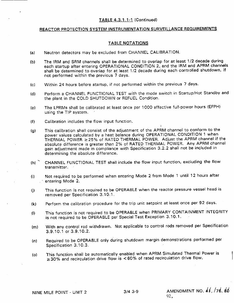
TABLE 4.3.1.1-1 (Continued)
REACTOR PROTECTION SYSTEM INSTRUMENTATION SURVEILLANCE REQUIREMENTS
TABLE NOTATIONS
(a) Neutron detectors may be excluded from CHANNEL CALIBRATION.
(b) The IRM and SRM channels shall be determined to overlap for at least 1/2 decade during
each startup after entering OPERATIONAL CONDITION 2, and the IRM and APRM channels
shall be determined to overlap for at least 1/2 decade during each controlled shutdown, if not performed within the previous 7 days.
(c) Within 24 hours before startup, if not performed within the previous 7 days.
(d) Perform a CHANNEL FUNCTIONAL TEST with the mode switch in Startup/Hot Standby and
the plant in the COLD SHUTDOWN or REFUEL Condition.
(e) The LPRMs shall be calibrated at least once per 1000 effective full-power hours (EFPH) using the TIP system.
(f) Calibration includes the flow input function.
(g) This calibration shall consist of the adjustment of the APRM channel to conform to the
power values calculated by a heat balance during OPERATIONAL CONDITION 1 when
THERMAL POWER _>25% of RATED THERMAL POWER. Adjust the APRM channel if the
absolute difference is greater than 2% of RATED THERMAL POWER. Any APRM channel
gain adjustment made in compliance with Specification 3.2.2 shall not be included in
determining the absolute difference.
(h) CHANNEL FUNCTIONAL TEST shall include the flow input function, excluding the flow transmitter.
(i) Not required to be performed when entering Mode 2 from Mode 1 until 12 hours after
entering Mode •.
(j) This function is not required to be OPERABLE when the reactor pressure vessel head is
removed per Specification 3.10:1.
(k) Perform the calibration procedure for the trip unit setpoint at least once per 92 days.
(I) This function is not required to be OPERABLE when PRIMARY CONTAINMENT INTEGRITY
is not required to be OPERABLE per Special Test Exception 3.10.1.
(m) With any control rod withdrawn. Not applicable to control rods removed per Specification
3.9.10.1 or 3.9.10.2.
(n) Required to be OPERABLE only during shutdown margin demonstrations performed per
Specification 3.10.3.
(o) This function shall be automatically enabled when APRM Simulated Thermal Power is
z>30% and recirculation drive flow is <60% of rated recirculation drive flow.
NINE MILE POINT - UNIT 2 3/4 3-9 AMENDMENT NO. di, /79, h 92,

TABLE 4.3.1.1-1 (Continued)
REACTOR PROTECTION SYSTEM INSTRUMENTATION SURVEILLANCE REQUIREMENTS
TABLE NOTATIONS
(p) Calibration includes verification that the OPRM Upscale trip is not bypassed when APRM Simulated Thermal Power is 230% and recirculation drive flow is <60% of rated recirculation drive flow. No test signal will be injected for the purpose of testing the algorithm. Calibration of the OPRM will consist of verification of OPRM upscale setpoints in the APRM instrument by the review of the "Show Parameters" display.
(q) No test signal will be injected during performance of this test. Functional testing of the OPRM will consist of toggling the appropriate outputs of the APRM instrument only.
NINE MILE POINT - UNIT 2 3/4 3-9a AMENDMENT NO. 92,
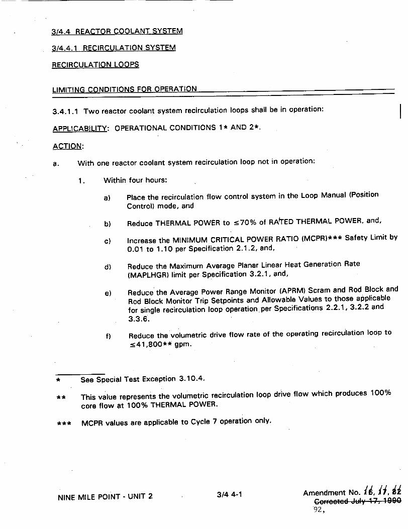
3/4.4 REACTOR COOLANT SYSTEM
314.4.1 RECIRCULATION SYSTEM
RECIRCULATION LOOPS
LIMITING CONDITIONS FOR OPERATION
3.4.1.1 Two reactor coolant system recirculation loops shall be in operation:
APPLICABILITY: OPERATIONAL CONDITIONS 1* AND 2*.
ACTION:
a. With one reactor coolant system recirculation loop not in operation:
1. Within four hours:
a) Place the recirculation flow control system in the Loop Manual (Position
Control) mode, and
b) Reduce THERMAL POWER to :570% of RA1TED THERMAL POWER, and,
c) Increase the MINIMUM CRITICAL POWER RATIO (MCPR)*** Safety Limit by
0.01 to 1.10 per Specification 2.1.2, and,
d) Reduce the Maximum Average Planar Linear Heat Generation Rate
(MAPLHGR) limit per Specification 3.2.1, and,
e) Reduce the Average Power Range Monitor (APRM) Scram and Rod Block and
Rod Block Monitor Trip Setpoints and Allowable Values to those applicable
for single recirculation loop operationper Specifications 2.2.1, 3.2.2 and
3.3.6.
f) Reduce the volumetric drive flow rate of the operating recirculation loop to
__41,800** gpm.
* See Special Test Exception 3.10.4.
** This value represents the volumetric recirculation loop drive flow which produces 100%
core flow at 100% THERMAL POWER.
*** MCPR values are applicable to Cycle 7 operation only.
NINE MILE POINT - UNIT 2 3/4 4-1 Amendment No. 116, H, i
Co2rctcd July 17, 1090 '92,ý
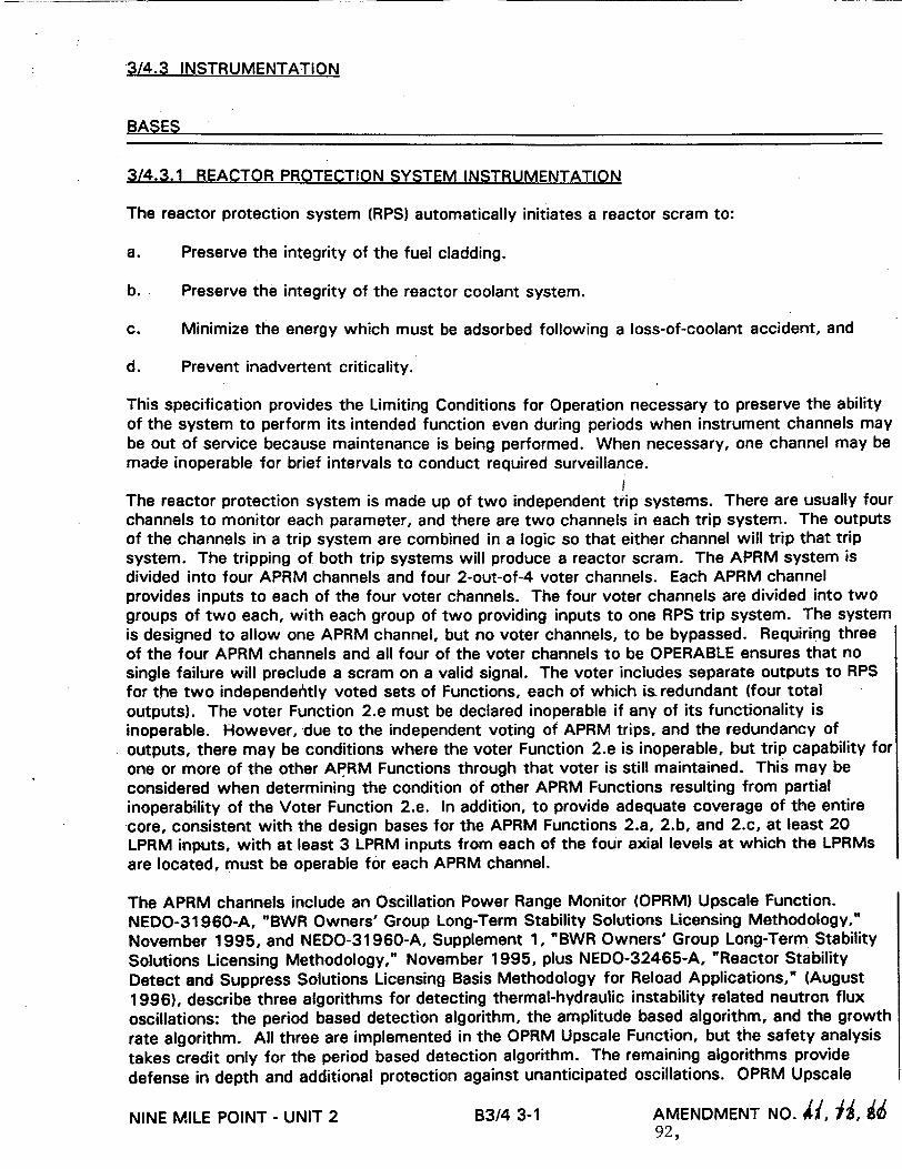
3/4.3 INSTRUMENTATION
BASES
3/4.3.1 REACTOR PROTECTION SYSTEM INSTRUMENTATION
The reactor protection system (RPS) automatically initiates a reactor scram to:
a. Preserve the integrity of the fuel cladding.
b. Preserve the integrity of the reactor coolant system.
c. Minimize the energy which must be adsorbed following a loss-of-coolant accident, and
d. Prevent inadvertent criticality.
This specification provides the Limiting Conditions for Operation necessary to preserve the ability of the system to perform its intended function even during periods when instrument channels may be out of service because maintenance is being performed. When necessary, one channel may be made inoperable for brief intervals to conduct required surveillance.
The reactor protection system is made up of two independent trip systems. There are usually four channels to monitor each parameter, and there are two channels in each trip system. The outputs of the channels in a trip system are combined in a logic so that either channel will trip that trip system. The tripping of both trip systems will produce a reactor scram. The APRM system is divided into four APRM channels and four 2-out-of-4 voter channels. Each APRM channel provides inputs to each of the four voter channels. The four voter channels are divided into two groups of two each, with each group of two providing inputs to one RPS trip system. The system is designed to allow one APRM channel, but no voter channels, to be bypassed. Requiring three of the four APRM channels and all four of the voter channels to be OPERABLE ensures that no single failure will preclude a scram on a valid signal. The voter includes separate outputs to RPS for the two independehtly voted sets of Functions, each of which is redundant (four total outputs). The voter Function 2.e must be declared inoperable if any of its functionality is inoperable. However, due to the independent voting of APRM trips, and the redundancy of outputs, there may be conditions where the voter Function 2.e is inoperable, but trip capability for one or more of the other APRM Functions through that voter is still maintained. This may be considered when determining the condition of other APRM Functions resulting from partial inoperability of the Voter Function 2.e. In addition, to provide adequate coverage of the entire core, consistent with the design bases for the APRM Functions 2.a, 2.b, and 2.c, at least 20 LPRM inputs, with at least 3 LPRM inputs from each of the four axial levels at which the LPRMs are located, must be operable for each APRM channel.
The APRM channels include an Oscillation Power Range Monitor (OPRM) Upscale Function. NEDO-31960-A, "BWR Owners' Group Long-Term Stability Solutions Licensing Methodology," November 1995, and NEDO-31960-A, Supplement 1, "BWR Owners' Group Long-Term Stability Solutions Licensing Methodology," November 1995, plus NEDO-32465-A, "Reactor Stability Detect and Suppress Solutions Licensing Basis Methodology for Reload Applications," (August 1996), describe three algorithms for detecting thermal-hydraulic instability related neutron flux oscillations: the period based detection algorithm, the amplitude based algorithm, and the growth rate algorithm. All three are implemented in the OPRM Upscale Function, but the safety analysis takes credit only for the period based detection algorithm. The remaining algorithms provide defense in depth and additional protection against unanticipated oscillations. OPRM Upscale
NINE MILE POINT - UNIT 2 B3/4 3-1 AMENDMENT NO. 4, J(, 1 92,
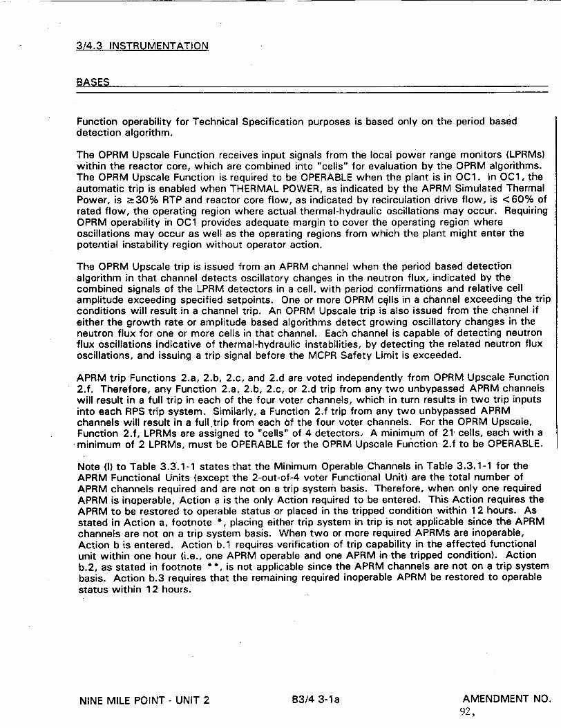
3/4.3 INSTRUMENTATION
BASES
Function operability for Technical Specification purposes is based only on the period based detection algorithm.
The OPRM Upscale Function receives input signals from the local power range monitors (LPRMs) within the reactor core, which are combined into "cells" for evaluation by the OPRM algorithms. The OPRM Upscale Function is required to be OPERABLE when the plant is in OC1. In OC1, the automatic trip is enabled when THERMAL POWER, as indicated by the APRM Simulated Thermal Power, is _>30% RTP and reactor core flow, as indicated by recirculation drive flow, is < 60% of rated flow, the operating region where actual thermal-hydraulic oscillations may occur. Requiring OPRM operability in OC1 provides adequate margin to cover the operating region where oscillations may occur as well as the operating regions from which the plant might enter the potential instability region without operator action.
The OPRM Upscale trip is issued from an APRM channel when the period based detection algorithm in that channel detects oscillatory changes in the neutron flux, indicated by the combined signals of the LPRM detectors in a cell, with period confirmations and relative cell amplitude exceeding specified setpoints. One or more OPRM cglls in a channel exceeding the trip conditions will result in a channel trip. An OPRM Upscale trip is also issued from the channel if either the growth rate or amplitude based algorithms detect growing oscillatory changes in the neutron flux for one or more cells in that channel. Each channel is capable of detecting neutron flux oscillations indicative of thermal-hydraulic instabilities, by detecting the related neutron flux oscillations, and issuing a trip signal before the MCPR Safety Limit is exceeded.
APRM trip Functions 2.a, 2.b, 2.c, and 2.d are voted independently from OPRM Upscale Function 2.f. Therefore, any Function 2.a, 2.b, 2.c, or 2.d trip from any two unbypassed APRM channels will result in a full trip in each of the four voter channels, which in turn results in two trip inputs into each RPS trip system. Similarly, a Function 2.f trip from any two unbypassed APRM channels will result in a full trip from each of the four voter channels. For the OPRM Upscale, Function 2.f, LPRMs are assigned to "cells" of 4 detectors, A minimum of 21. cells, each with a
.minimum of 2 LPRMs, must be OPERABLE for the OPRM Upscale Function 2.f to be OPERABLE.
Note (I) to Table 3.3.1-1 states that the Minimum Operable Channels in Table 3.3.1-1 for the APRM Functional Units (except the 2-out-of-4 voter Functional Unit) are the total number of APRM channels required and are not on a trip system basis. Therefore, when only one required APRM is inoperable, Action a is the only Action required to be entered. This Action requires the APRM to be restored to operable status or placed in the tripped condition within 12 hours. As stated in Action a, footnote *, placing either trip system in trip is not applicable since the APRM channels are not on a trip system basis. When two or more required APRMs are inoperable, Action b is entered. Action b.1 requires verification of trip capability in the affected functional unit within one hour (i.e., one APRM operable and one APRM in the tripped condition). Action b.2, as stated in footnote **, is not applicable since the APRM channels are not on a trip system basis. Action b.3 requires that the remaining required inoperable APRM be restored to operable status within 12 hours.
NINE MILE POINT - UNIT 2 B3/4 3-1a AMENDMENT NO. 92,
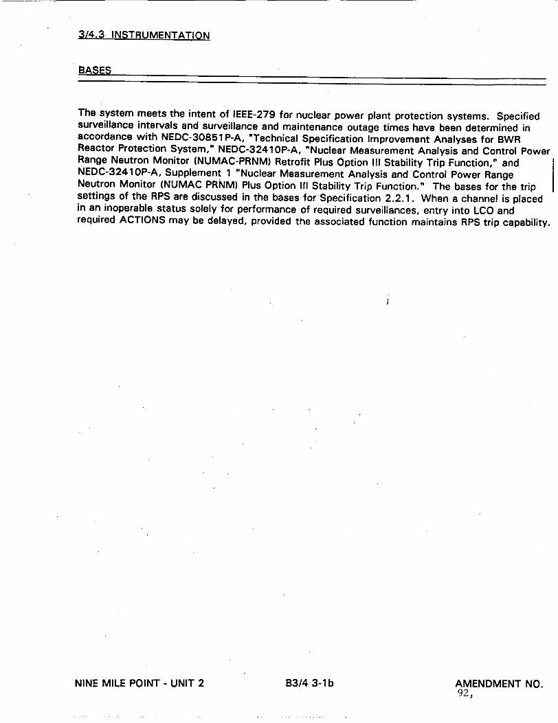
3/4.3 INSTRUMENTATION
BASES
The system meets the intent of IEEE-279 for nuclear power plant protection systems. Specified surveillance intervals and surveillance and maintenance outage times have been determined in accordance with NEDC-30851 P-A, "Technical Specification Improvement Analyses for BWR Reactor Protection System," NEDC-3241OP-A, "Nuclear Measurement Analysis and Control Power Range Neutron Monitor (NUMAC-PRNM) Retrofit Plus Option III Stability Trip Function," and NEDC-32410P-A, Supplement 1 "Nuclear Measurement Analysis and Control Power Range Neutron Monitor (NUMAC PRNM) Plus Option III Stability Trip Function." The bases for the trip settings of the RPS are discussed in the bases for Specification 2.2.1. When a channel is placed in an inoperable status solely for performance of required surveillances, entry into LCO and required ACTIONS may be delayed, provided the associated function maintains RPS trip capability.
IB3/4 3-1 b AMENDMENT NO. 92,
NINE MILE POINT - UNIT 2
3/4.4 REACTOR COOLANT SYSTEM
BASES
3/4.4.1 RECIRCULATION SYSTEM
The impact of single recirculation loop operation upon plant safety is assessed and shows that single-loop operation is permitted if the MCPR fuel cladding safety limit is increased as noted by Specification 2.1.2, APRM scram and control rod block setpoints are adjusted as noted in Tables 2.2.1-1 and 3.3.6-2, respectively, MAPLHGR limits are decreased by the factor given in Specification 3.2.1, and MCPR operating limits are adjusted per Section 3/4.2.3.
Additionally, surveillance on the volumetric drive flow rate of the operating recirculation loop is imposed to exclude the possibility of excessive core internals vibration. Drive flow is the flow rate for the recirculation pump in the operating loop. The surveillance on differential temperatures below 30% THERMAL POWER or 50% rated jet pump loop flow is to mitigate the undue thermal stress on vessel nozzles, recirculation pump and vessel bottom head during the extended operation of the single recirculation loop mode. Jet pump loop flow is the sum of the flows through the 10 jet pumps in one loop. Core flow is the sum of the two jet pump loop flows.
An inoperable jet pump is not, in itself, a sufficient reason to declare a recirculation loop inoperable, but it does, in case of a design-basis accident, increase the blowdown area and reduce the capability of reflooding the core; thus, the requirement for shutting down the facility when a jet pump is inoperable. Jet pump failure can be detected by monitoring jet pump performance on a prescribed schedule for significant degradation.
Jet pump loop flow mismatch limits are in compliance with the ECCS LOCA analysis design criteria for two recirculation loop operation. The limits will ensure an adequate core flow coastdown from either recirculation loop after a LOCA. In the case where the mismatch limits cannot be maintained during two loop operation, continued operation is permitted in a single
recirculation loop mode.
In order to prevent undue stress on the vessel nozzles and bottom head region, the recirculation loop temperatures shall be within 50°F of each other before startup of an idle loop. The loop
temperature must also be within 50°F of the reactor pressure vessel coolant temperature to
prevent thermal shock to the
NINE MILE POINT - UNIT 2 B3/4 4-1 AMENDMENT NO. 92,

THIS PAGE LEFT INTENTIONALLY BLANK
NINE MILE POINT - UNIT 2 B3/4 4-2 AMENDMENT NO. U 92,
I
ADMINISTRATIVE CONTROLS
,SEMIANNUAL RADIOACTIVE EFFLUENT RELEASE REPORT
6.9.1.8 (Continued)
The Semiannual Radioactive Effluent Release Reports shall include any changes made during the reporting period to the PROCESS CONTROL PROGRAM (PCP) and to the OFFSITE DOSE CALCULATION MANUAL (ODCM), pursuant to Specifications 6.13 and 6.14, respectively, as wel as any major change to liquid, gaseous, or solid radwaste treatment systems pursuant to Specification 6.15. It shall also include a listing of new locations for dose calculations and/or environmental monitoring identified by the land use census pursuant to Specification 3.12.2.
The Semiannual Radioactive Effluent Release Reports shall also include the following: an explanation of why the inoperability of liquid or gaseous effluent monitoring instrumentation was not corrected within the time specified in Specification 3.3.7.9 or 3.3.7.10, respectively, and a description of the events leading to liquid holdup tanks exceeding the limits of Specification 3.11.1.4.
CORE OPERATING LIMITS REPORT
6.9.1.9
a. Core operating limits shall be established prior to each reload cycle, or prior to any remaining portion of a reload cycle for the following:
1) The AVERAGE PLANAR LINEAR HEAT GENERATION RATE (APLHGR) for Specification 3.2.1.
2) The Average Power Range Monitor (APRM) flow-biased simulated thermal power
upscale scram trip setpoint for Specification 3.2.2.
3) The Kf core flow adjustment factor for Specification 3.2.3.
4) The MINIMUM CRITICAL POWER RATIO (MCPR) for Specification 3.2.3.
5) The LINEAR HEAT*GENERATION RATE (LHGR) for Specification 3.2.4.
6) Control Rod Block Instrumentation Setpoint for the rod block monitor upscale trip setpoint and allowable value for Specification 3.3.6.
7) Oscillation Power Range Monitor Upscale for Table 2.2.1-1.
and shall be documented in the CORE OPERATING LIMITS REPORT.
b. The analytical methods used to determine the core operating limits shall be those previously reviewed and approved by the NRC, specifically those described in the following documents.
1) The GESTR-LOCA and SAFER Models of the Evaluation of the Loss-of-Coolant Accident - SAFER/GESTR Application Methodology, NEDE-23785-1-PA, latest approved revision.
NINE MILE POINT - UNIT 2 6-22 Amendment No. i, i, I 92,
ADMINISTRATIVE CONTROLS
CORE OPERATING LIMITS REPORT
6.9.1.9 (Continued)
2) General Electric Standard Application for Reactor Fuel, NEDE-2401 1-P-A-US, latest approved revision.
3) NEDO-32465-A, Reactor Stability Detect and Suppress Solutions Licensing Basis Methodology for Reload Applications, August 1996.
c. The core operating limits shall be determined such that all applicable limits (e.g., fuel thermal-mechanical limits, core thermal-hydraulic limits, ECCS limits, nuclear limits such as shutdown margin, transient analysis limits, and accident analysis limits) of the safety analysis are met.
d. The CORE OPERATING LIMITS REPORT, including any mid-cycle revisions or supplements shall be provided, upon issuance for each reload cycle, to the NRC Document Control Desk with copies to the Regional Administrator and Resident Inspector.
SPECIAL REPORTS
6.9.2 Special reports shall be submitted in accordance with 10 CFR 50.4 within the time period specified for each report.
6.10 RECORD RETENTION
6.10.1 In addition to the applicable record retention requirements of Title 10, of the Code of Federal Regulations (10 CFR), the following records shall be retained for at least the minimum period indicated.
6.10.1.1 The followipg records shall be retained for at least 5 years:
a. Records and logs of unit operation covering time interval at each power level
b. Records and logs of principal maintenance activities, inspections, repair, and replacement of principal items of equipment related to nuclear safety
c. All REPORTABLE EVENTS submitted to the Commission
d. Records of surveillance activities, inspections, and calibrations required by these Technical Specifications
e. Records of changes made to the procedures required by Specification 6.8.1
f. Records of radioactive shipments
g. Records of sealed source and fission detector leak tests and results
h. Records of annual physical inventory of all sealed source material of record
92, NINE MILE POINT - UNIT 2 6-23 Amendment No. ;
REACTOR COOLANT SYSTEM
RECIRCULATION--SYSTEM.
RECI RCULATI ON- -LOOPS,
LIMITING CONDITIONS FOR OPERATION (Continued)
g) Perform Surveillance. Requirement 4.4.1.1.2 if THERMAL POWER is < 30%* of RATEDTHERMAL POWER or the jet pump loop flow in the operating loop is < 50%* of rated jet pump loop flow.
2. The provisions of Specification 3.0.4 are not applicable.
3. Otherwise be in at least HOT SHUTDOWN within the next 12 hours.
b. With no reactor coolant system recirculation loops in operation, place the unit in at least STARTUP within six hours and in HOT SHUTDOWN within the next six hours.
* Final values were determined during Startup Testing based upon the actual THERMAL POWER and jet pump loop flow which will sweep the cold water from the vessel bottom head preventing stratification.
NINE MILE POINT - UNIT 2 3/4 4-2 AMENDMENT NO. 92,
REACTOR COOLANT SYSTEM
RECIRCULATION SYSTEM
RECIRCULATION LOOPS
SURVEILLANCE REQUIREMENTS
4.4.1.1.1 With one reactor coolant system recirculation loop not in operation, at least once per 12 hours verify that:
a. Reactor THERMAL POWER is :s 70% of RATED THERMAL POWER,
b. The recirculation flow control system is in the Loop Manual (Position Control) mode, and
c. The volumetric drive flow rate of the operating loop is __ 41,800 gpm.*
4.4.1.1.2 With one reactor coolant system recirculation loop not in operation, within no more than 15 minutes prior to either THERMAL POWER increase or jet pump loop flow increase, verify that the following differential temperature requirements are met if THERMAL POWER is _s 30%** I of RATED THERMAL POWER or the recirculation jet pump loop flow in the operating recirculation loop is <s 50%** of rated jet pump loop flow: I
a. -s 145 0 F between reactor vessel steam space coolant and bottom head drain line coolant,
b. -s 50°F between the reactor coolant within the loop not in operation and the coolant in the reactor pressure vessel, and
C; . < 50°F between the reactor coolant within the loop not in operation and the operating loop.
The differential temperature requirements of Specification 4.4.1.1.2 b. and c. do not apply when the loop not in operation is isolated from the reactor pressure vessel:
* This value represents the volumetric recirculation loop drive flow which produces 100% core flow at 100% THERMAL POWER.
** Final values were determined during Startup Testing based upon the actual THERMAL POWER and jet pump loop flow which will sweep the cold water from the vessel bottom head preventing stratification.
NINE MILE POINT - UNIT 2 Amendment No. 92,
3/4 4-3
REACTOR COOLANT SYSTEM
RECIRCULATION SYSTEM
RECIRCULATION LOOPS
SURVEILLANCE REQUIREMENTR I(rnntinisaril
4.4.1.1.3 Each reactor coolant system recirculation loop flow control valve shall be demonstrated OPERABLE at least once per 18 months by:
a. Verifying that the control valve fails "as is" on loss of hydraulic pressure at the hydraulic control unit, and
b. Verifying that the average rate of control valve movement is:
1. Less than or equal to 11 % of stroke per second opening, and
2. Less than or equal to 11 % of stroke per second closing.
NINE MILE POINT - UNIT 2 AMENDMENT NO. 92,
3/4 4-4
FIGURE 3.4.1.1-1 HAS BEEN DELETED
NINE MILE POINT - UNIT 2 Amendment No. 92,
3/4 4-5

RPS Instrumentation 3.3.1.1
3.3 INSTRUMENTATION
3.3.1.1 Reactor Protection System (RPS) Instrumentation
LCO 3.3.1.1
APPLICABILITY:
The RPS instrumentation for each Function in Table 3.3.1.1-1 shall be OPERABLE.
According to Table 3.3.1.1-1.
-NOTESeparate Condition entry is allowed for each channel. ----------------------------------------------------------------
CONDITION REQUIRED ACTION COMPLETION TIME
A. One or more required A.1 Place channel in 12 hours
channels inoperable, trip.
OR
A.2 Place associated trip 12 hours system in trip.
B. --- NOTE----Not applicable for Functions 2.a, 2.b, 2.c, 2.d, and 2.e.
One or more Functions B.1 Place channel in one 6 hours with one or more trip system in trip. required channels inoperable in both OR trip systems.
B.2 Place one trip system 6 hours in trip.
(continued)
Amendment 91, 92
ACTIONS
I
3.3.1.1-1NMP2

RPS Instrumentation 3.3.1.1
ACTIONS (continued)
CONDITION REQUIRED ACTION COMPLETION TIME
C. One or more Functions C.1 Restore RPS trip 1 hour with RPS trip capability. capability not maintained.
D. Required Action and D.1 Enter the Condition Immediately associated Completion referenced in Time of Condition A, Table 3.3.1.1-1 for the B, or C not met. channel.
E. As required by E.1 Reduce THERMAL POWER to 4 hours Required Action D.1 < 30% RTP. and referenced in Table 3.3.1.1-1.
F. As required by F.1 Initiate alternate 12 hours Required Action D.1 method to detect and and referenced in suppress thermalTable 3.3.1.1-1. hydraulic instability
oscillations.
AND
F.2 Restore required channel 120 days to OPERABLE status.
G. Required Action and G.1 Be in MODE 2. 6 hours associated Completion Time of Condition F not met.
.OR
As required by Required Action D.1 and referenced in Table 3.3.1.1-1.
(continued)
Amendment F1, 923.3.1.1-2NMP2
RPS Instrumentation 3.3.1.1
ACTIONS (continued)
CONDITION REQUIRED ACTION COMPLETION TIME
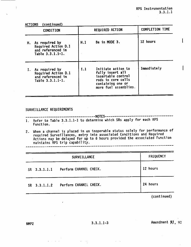
H. As required by H.1 Be in MODE 3. 12 hours Required Action D.1 and referenced in Table 3.3.1.1-1.
I. As required by 1.1 Initiate action to Immediately Required Action D.1 fully insert all and referenced in insertable control Table 3.3.1.1-1. rods in core cells
containing one or more fuel assemblies.
SURVEILLANCE REQUIREMENTS
--------------------NOTES
1. Refer to Table 3.3.1.1-1 to determine which SRs apply for each-RPS Function.
2. When a channel is placed in an inoperable status solely for performance of required Surveillances, entry into associated Conditions and Required Actions may be delayed for up to 6 hours provided the associated Function maintains RPS trip capability.
-----------------------------------------------------------------
SURVEILLANCE FREQUENCY
SR 3.3.1.1.1 Perform CHANNEL CHECK. 12 hours
SR 3.3.1.1.2 Perform CHANNEL CHECK. 24 hours
(continued)
Amendment 91, 923.3.1.1-3
I
I
NMP2
RPS Instrumentation 3.3.1.1
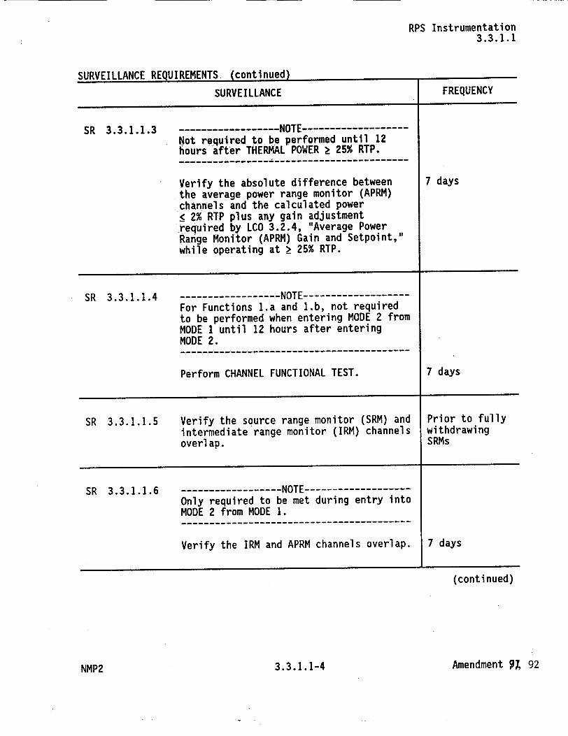
eIrngrTI i AMr� Drn�I1DVMflJT� Ir�nntinug�rI� .�UF�Y LI LLrII�'..L I�L�(�.IL I�LI Il�IlI Y."*r* *
SURVEILLANCE
SR 3.3.1.1.3 -------------------NOTE--------------Not required to be performed until 12 hours after THERMAL POWER ý 25% RTP. --------------- -----------------------
Verify the absolute difference between the average power range monitor (APRM) channels and the calculated power •2% RTP plus any gain adjustment required by LCO 3.2.4, "Average Power Range Monitor (APRM) Gain and Setpoint," while operating at 2 25% RTP.
FREQUENCY
7 days
SR 3.3.1.1.4 ----------------- NOTE --------------For Functions 1.a and 1.b, not required to be performed when entering MODE 2 from MODE 1 until 12 hours after entering MODE 2. --------------------------------------
Perform CHANNEL FUNCTIONAL TEST. 7 days
SR 3.3.1.1.5 Verify the source range monitor (SRM) and Prior to fully intermediate range monitor (IRM) channels withdrawing overlap. SRMs
SR 3.3.1.1.6 ----------- NOTE---------Only required to be met during entry into MODE 2 from MODE 1. ----------------------------------------
Verify the IRM and APRM channels overlap. 7 days
(continued)
Amendment 94 923.3.1.1-4
"nxtrTi i AKirr Drn1iTDrmrMT4Z rnn+innnAl
NMP2
RPS Instrumentation 3.3.1.1
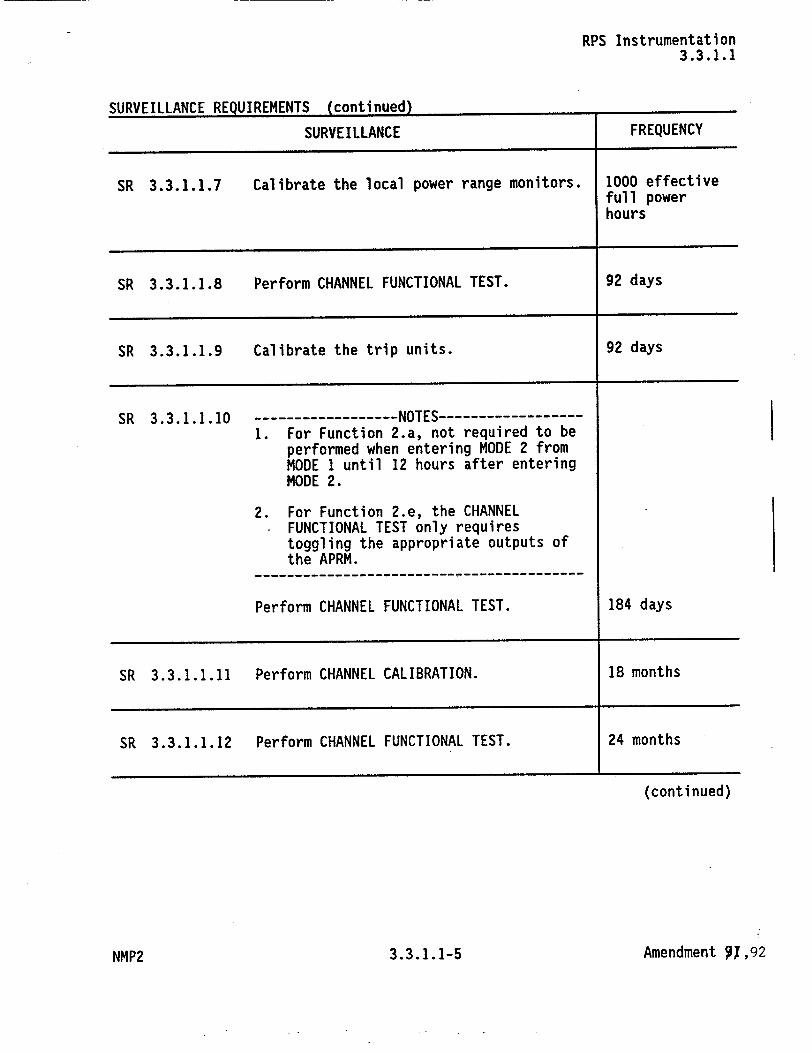
SURVEILLANCE REQUIREMENTS (continued)
SURVEILLANCE FREQUENCY
SR 3.3.1.1.7 Calibrate the local power range monitors. 1000 effective full power hours
SR 3.3.1.1.8 Perform CHANNEL FUNCTIONAL TEST. 92 days
SR 3.3.1.1.9 Calibrate the trip units. 92 days
SR 3.3.1.1.10 ----------------- NOTES-------------1. For Function 2.a, not required to be
performed when entering MODE 2 from MODE 1 until 12 hours after entering MODE 2.
2. For Function 2.e, the CHANNEL FUNCTIONAL TEST only requires toggling the appropriate outputs of the APRM.
--------------------------------------
Perform CHANNEL FUNCTIONAL TEST. 184 days
SR 3.3.1.1.11 Perform CHANNEL CALIBRATION. 18 months
SR 3.3.1.1.12 Perform CHANNEL FUNCTIONAL TEST. 24 months
(continued)
Amendment 91,92
I
3.3.1.1-5NMP2
RPS Instrumentation 3.3.1.1
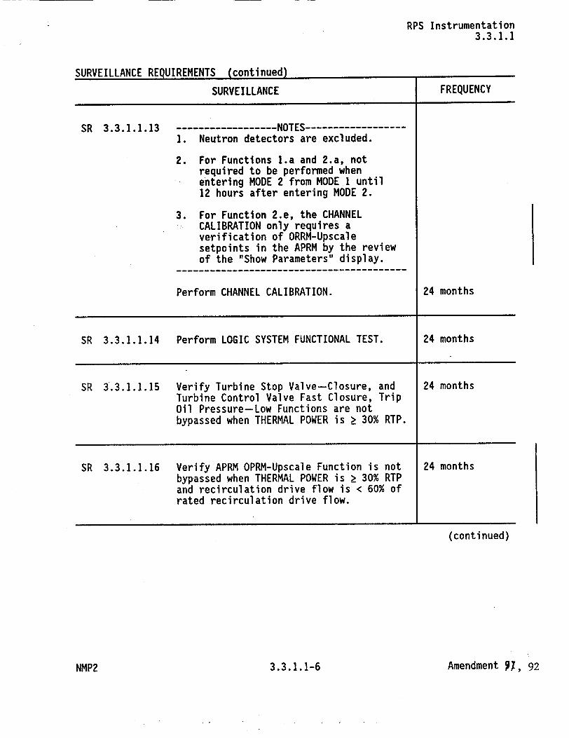
c�IIDlIFTI I nwrr RFAIITRFMFNT� (�-nntiniu�d�
SURVEILLANCE
SR 3.3.1.1.13 -------------------NOTES-------------1. Neutron detectors are excluded.
2. For Functions l.a and 2.a, not required to be performed when entering MODE 2 from MODEI until 12 hours after entering MODE 2.
3. For Function 2.e, the CHANNEL CALIBRATION only requires a verification of ORRM-Upscale setpoints in the APRM by the review of the "Show Parameters" display.
Perform CHANNEL CALIBRATION.
FREQUENCY
24 months
SR 3.3.1.1.14 Perform LOGIC SYSTEM FUNCTIONAL TEST. 24 months
SR 3.3.1.1.15 Verify Turbine Stop Valve-Closure, and 24 months Turbine Control Valve Fast Closure, Trip Oil Pressure-Low Functions are not bypassed when THERMAL POWER is Ž 30% RTP.
SR 3.3.1.1.16 Verify APRM OPRM-Upscale Function is not 24 months bypassed when THERMAL POWER is > 30% RTP and recirculation drive flow is < 60% of rated recirculation drive flow.
(continued)
Amendment 91, 92
IMOVPTHAtirr Prn"TQrM1:NT4Z frnntinnad) i
i
3.3.1.1-6NMP2
RPS Instrumentation 3.3.1.1
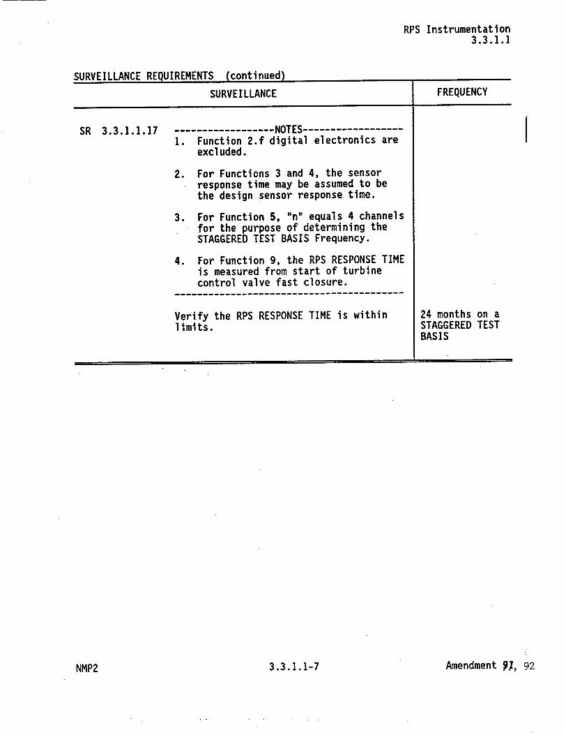
CIIDIWT~iAr I DFrnIT~rMPNT4Z (enriinIIedl -..
SURVEILLANCE
SR 3.3.1.1.17
t
-----------NOTES--------1. Function 2.f digital electronics are
excluded.
2. For Functions 3 and 4, the sensor response time may be assumed to be the design sensor response time.
3. For Function 5, 'n" equals 4 channels for the purpose of determining the STAGGERED TEST BASIS Frequency.
4. For Function 9, the RPS RESPONSE TIME is measured from start of turbine control valve fast closure.
-- - - - - - - - - - - - - - - --------
Verify the RPS RESPONSE TIME is within limits.
FREQUENCY
24 months on a STAGGERED TEST BASIS
Amendment 91, 92NMP2 3.3.1.1-7
RPS Instrumentation 3.3.1.1
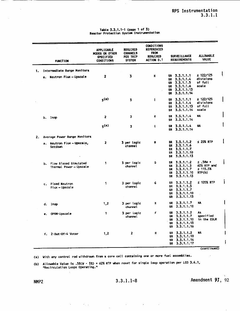
Table 3.3.1.1-1 (page 1 of 3) Reactor Protection System Instrumentation
CONDITIONS APPLICABLE REQUIRED REFERENCED
MODES OR OTHER CHANNELS FROM SPECIFIED PER TRIP REQUIRED SURVEILLANCE ALLOWABLE
FUNCTION CONDITIONS SYSTEM ACTION D.1 REQUIREMENTS VALUE
1. Intermediate Range Monitors
a. Neutron Flux-Upscale 3
3
3
3
SR SR SR SR SR SR
SR SR SR SR
H SR 3.3.1.1.4 SR 3.3.1.1.14
I SR 3.3.1.1.4 SR 3.3.1.1.14
2. Average Power Range Monitors
a. Neutron Flux-Upscale, Setdown
b. Flow Biased Simulated Thermal Power - Upscale
c. Fixed Neutron Flux - Upscale
d. Inop
e. OPRM-Upscate
f. 2-Out-Of-4 Voter
2 3 per logic channel
1 3 per Logic channel
1 3 per logic channel
1,2 3 per logic channel
1 3 per logic channel
1,2 2
(continued)
(a) With any control rod withdrawn from a core cell containing one or more fuel assemblies.
(b) AtLowable Value is .58(W - 5%) + 62% RTP when reset for single loop operation per LCO 3.4.1.
"Recirculation Loops Operating."
NMP2 3.3.1.1-8 Amendment 91, 92
2
b. Inop
5(a)
2
5(a)
3.3.1.1.1 3.3.1.1.4 3.3.1.1.5 3.3.1.1.6 3.3.1.1.13 3.3.1.1.14
3.3.1.1.1 3.3.1.1.4 3.3.1.1.13 3.3.1.1.14
s 122/125 divisions of full scale
s 122/125 divisions of full scale
NA
NA
H SR SR SR SR SR
G SR SR SR SR SR
G SR SR SR SR SR
H SR SR
F SR SR SR SR SR
H SR SR SR SR
3.3.1.1.2 3.3.1.1.6 3.3.1.1.7 3.3.1.1.10 3.3.1.1.13
3.3.1.1.2 3.3.1.1.3 3.3.1.1.7 3.3.1.1.10 3.3.1.1.13
3.3.1.1.2 3.3.1.1.3 3.3.1.1.7 3.3.1.1.10 3.3.1.1.13
3.3.1.1.7 3.3.1.1.10
3.3.1.1.2 3.3.1.1.7 3.3.1.1.10 3.3.1.1.13 3.3.1.1.16
3.3.1.1.2 3.3.1.1.10 3.3.1.1.14 3.3.1.1.17
s 20% RTP
s .58W + 62% RTP and s 115.5% RTP(b)
s 120% RTP
NA
As specified in the COLR
NA
I
I
I
RPS Instrumentation 3.3.1.1
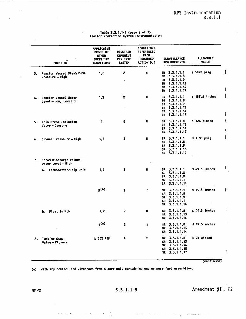
Table 3.3.1.1-1 (page 2 of 3) Reactor Protection System Instrumentation
APPLICABLE CONDITIONS MODES OR REQUIRED REFERENCED
OTHER CHANNELS FROM SPECIFIED PER TRIP REQUIRED SURVEILLANCE ALLOWABLE
FUNCTION CONDITIONS SYSTEM ACTION D.1 REQUIREMENTS VALUE
3. Reactor Vessel Steam Dome Pressure- High
4. Reactor Vessel Water Level - Low, Level 3
5. Main Steam Isolation Valve - Closure
6. Drywelt Pressure-High
7. Scram Discharge Volume
Water Level -High
a. Transmitter/Trip Unit
b. Float Switch
8. Turbine Stop VaLve - Closure
1,2
1,2
1,2
1,2
5 (a)
1,2
5 (a)
2
2
8
2
2
2
2
2
S30% RTP
H SR SR SR SR SR SR
H SR SR SR SR SR SR
G SR SR SR SR
H SR SR SR SR SR
H SR SR SR SR SR
SR SR SR SR SR
H SR SR SR
SR SR SR
E SR SR SR SR SR
3.3.1.1.1 3.3.1.1.8 3.3.1.1.9 3.3.1.1.13 3.3.1.1.14 3.3.1.1.17
3.3.1.1.1 3.3.1.1.8 3.3.1.1.9 3.3.1.1.13 3.3.1.1.14 3.3.1.1.17
3.3.1.1.8 3.3.1.1.13 3.3.1.1.14 3.3.1.1.17
3.3.1.1.1 3.3.1.1.8 3.3.1.1.9 3.3.1.1.13 3.3.1.1.14
3.3.1.1.1 3.3.1.1.8 3.3.1.1.9 3.3.1.1.11 3.3.1.1.14
3.3.1.1.1 3.3.1.1.8 3.3.1.1.9 3.3.1.1.11 3.3.1.1.14
3.3.1.1.8 3.3.1.1.13 3.3.1.1.14
3.3.1.1.8 3.3.1.1.13 3.3.1.1.14
3.3.1.1.8 3.3.1.1.13 3.3.1.1.14 3.3.1.1.15 3.3.1.1.17
< 1072 psig
S157.8 inches
S 12% closed
S 1.88 psig
s 49.5 inches
s 49.5 inches
5 49.5 inches
s 49.5 inches
5 7% closed
Amendment ,1 , 92
(continued)
(a) With any control rod withdrawn from a core cell containing one or more fuel assemblies.
I
I
3.3.1.1-9NMP2

RPS Instrumentation 3.3.1.1
Table 3.3.1.1-1 (page 3 of 3) Reactor Protection System instrumentation
APPLICABLE CONDITIONS MODES OR REQUIRED REFERENCED
OTHER CHANNELS FROM4 SPECIFIED PER TRIP REQUIRED SURVEILLANCE ALLOWABLE
FUNCTION CONDITIONS SYSTEM ACTION D.1 REQUIREMENTS VALUE
9. Turbine Control Valve t 30% RTP 2 E SR 3.3.1.1.8 > 465 psig
Fast Closure, Trip Oil SR 3.3.1.1.13
Pressure- Low SR 3.3.1.1.14 SR 3.3.1.1.15 SR 3.3.1.1.17
10. Reactor Mode 1,2 2 H SR 3.3.1.1.12 NA
Switch- Shutdown Position SR 3.3.1.1.14
5 (a) 2 I SR 3.3.1.1.12 NA
SR 3.3.1.1.14
11. Manual Scram 1,2 4 H SR 3.3.1.1.4 NA SR 3.3.1.1.14
5 (a) 4 SR 3.3.1.1.4 NA
SR 3.3.1.1.14
(a) With any control rod withdrawn from a core cell containing one or more fuel assemblies.
Amendment 91, 923.3.1.1-10NMP2
RPS Instrumentation B 3.3.1.1
BASES
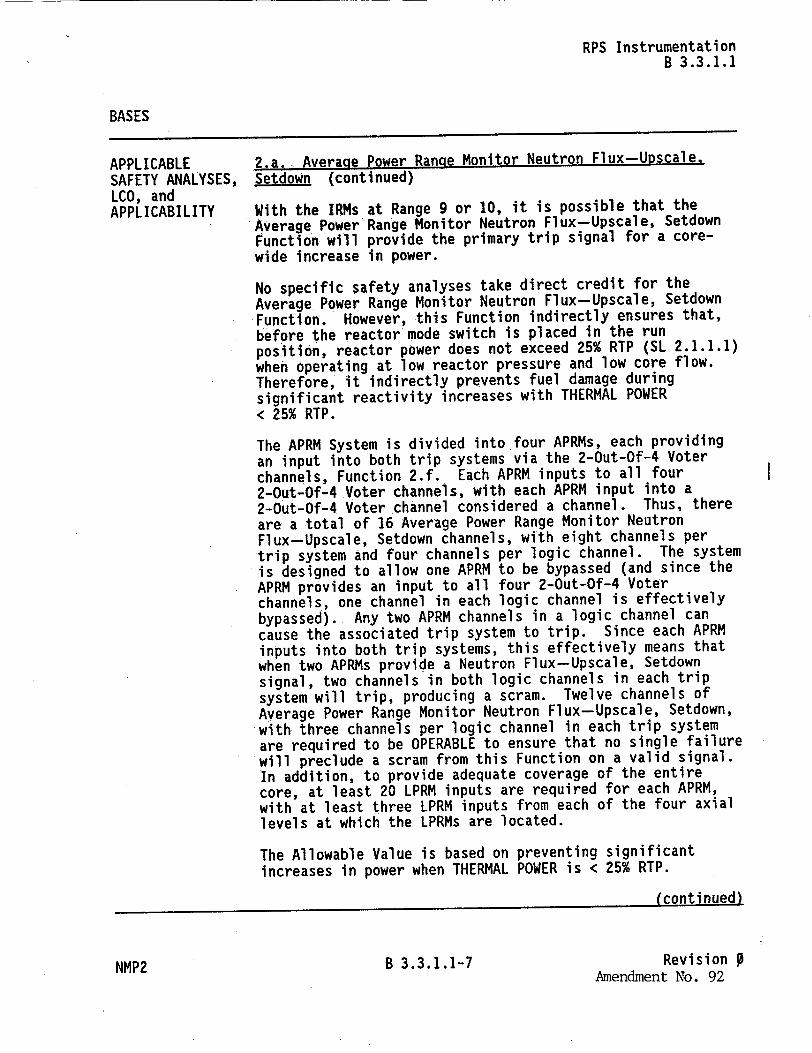
APPLICABLE 2.a.. Average Power Range Monitor Neutron Flux-Upscale, SAFETY ANALYSES, Setdown (continued) LCO, and APPLICABILITY With the IRMs at Range 9 or 10, it is possible that the
Average Power Range Monitor Neutron Flux-Upscale, Setdown Function will provide the primary trip signal for a corewide increase in power.
No specific safety analyses take direct credit for the
Average Power Range Monitor Neutron Flux-Upscale, Setdown Function. However, this Function indirectly ensures that, before the reactor mode switch is placed in the run position, reactor power does not exceed 25% RTP (SL 2.1.1.1) when operating at low reactor pressure and low core flow. Therefore, it indirectly prevents fuel damage during significant reactivity increases with THERMAL POWER < 25% RTP.
The APRM System is divided into four APRMs, each providing an input into both trip systems via the 2-Out-Of-4 Voter channels, Function 2.f. Each APRM inputs to all four 2-Out-Of-4 Voter channels, with each APRM input into a 2-Out-Of-4 Voter channel considered a channel. Thus, there are a total of 16 Average Power Range Monitor Neutron Flux-Upscale, Setdown channels, with eight channels per trip system and four channels per logic channel. The system is designed to allow one APRM to be bypassed (and since the APRM provides an input to all four 2-Out-Of-4 Voter channels, one channel in each logic channel is effectively bypassed). Any two APRM channels in a logic channel can cause the associated trip system to trip. Since each APRM inputs into both trip systems, this effectively means that when two APRMs provide a Neutron Flux-Upscale, Setdown signal, two channels in both logic channels in each trip system will trip, producing a scram. Twelve channels of Average Power Range Monitor Neutron Flux-Upscale, Setdown, with three channels per logic channel in each trip system are required to be OPERABLE to ensure that no single failure will preclude a scram from this Function on a valid signal. in addition, to provide adequate coverage of the entire core, at least 20 LPRM inputs are required for each APRM, with at least three LPRM inputs from each of the four axial levels at which the LPRMs are located.
The Allowable Value is based on preventing significant increases in power when THERMAL POWER is < 25% RTP.
(continued)
NMP2 B 3.3.1.1-7 Revision Amendment No. 92
RPS Instrumentation B 3.3.1.1
BASES
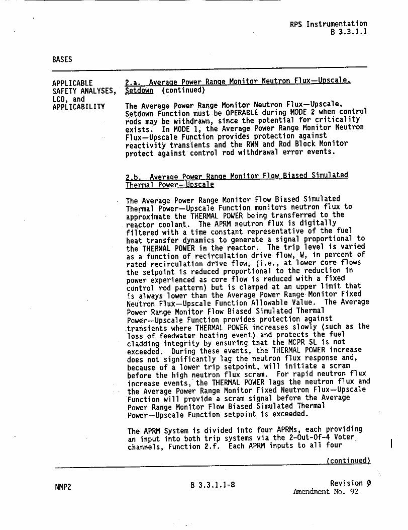
APPLICABLE 2.a. Average Power Range Monitor Neutron Flux-Upscale, SAFETY ANALYSES, Setdown (continued) LCO, and APPLICABILITY The Average Power Range Monitor Neutron Flux-Upscale,
Setdown Function must be OPERABLE during MODE 2 when control rods may be withdrawn, since the potential for criticality exists. In MODE I, the Average Power Range Monitor Neutron Flux-Upscale Function provides protection against reactivity transients and the RWM and Rod Block Monitor protect against control rod withdrawal error events.
2.b. Average Power Range Monitor Flow Biased Simulated Thermal Power-Upscale
The Average Power Range Monitor Flow Biased Simulated Thermal Power-Upscale Function monitors neutron flux to approximate the THERMAL POWER being transferred to the reactor coolant. The APRM neutron flux is digitally filtered with a time constant representative of the fuel heat transfer dynamics to generate a signal proportional to the THERMAL POWER in the reactor. The trip level is varied as a function of recirculation drive flow, W, in percent of rated recirculation drive flow, (i.e., at lower core flows the setpoint is reduced proportional to the reduction in power experienced as core flow is reduced with a fixed control rod pattern) but is clamped at an upper limit that is always lower than the Average Power Range Monitor Fixed Neutron Flux-Upscale Function Allowable Value. The Average Power Range Monitor Flow Biased Simulated Thermal Power-Upscale Function provides protection against transients where THERMAL POWER increases slowly (such as the loss of feedwater heating event) and protects the fuel cladding integrity by ensuring that the MCPR SL is not exceeded. During these events, the THERMAL POWER increase does not significantly lag the neutron flux response and, because of a lower trip setpoint, will initiate a scram before the high neutron flux scram. For rapid neutron flux increase events, the THERMAL POWER lags the neutron flux and the Average Power Range Monitor Fixed Neutron Flux-Upscale Function will provide a scram signal before the Average Power Range Monitor Flow Biased Simulated Thermal Power-Upscale Function setpoint is exceeded.
The APRM System is divided into four APRMs, each providing an input into both trip systems via the 2-Out-Of-4 Voter channels, Function 2.f. Each APRM inputs to all four
(continued)
NMP2 B 3.3.1.1-8 Revision Amendment No. 92
RPS Instrumentation B 3.3.1.1
BASES
APPLICABLE 2.b. Average Power Range Monitor Flow Biased Simulated SAFETY ANALYSES, Thermal Power-Upscale (continued) LCO, and APPLICABILITY� The Average Power Range Monitor Flow Biased Simulated
Thermal Power-Upscale Function is required to be OPERABLE in MODE I when there is the possibility of generating excessive THERMAL.POWER and potentially exceeding the SL applicable to high pressure and core flow conditions (MCPR SL). During MODES 2 and 5, other IRM and APRM Functions provide protection for fuel cladding integrity.
2.c. Average Power Range Monitor Fixed Neutron Flux-Upscale
The APRM channels provide the primary indication of neutron flux within the core and respond almost instantaneously to neutron flux increases. The Average Power Range Monitor Fixed Neutron Flux-Upscale Function is capable of generating a trip signal to prevent fuel damage or excessive Reactor Coolant System pressure. For the overpressurization protection analysis of Reference 2, the Average Power Range Monitor Fixed Neutron Flux-Upscale Function is assumed to terminate the main steam isolation valve (MSIV) closure event and, along with the safety/relief valves (S/RVs), limits the peak reactor pressure vessel (RPV) pressure to less than the ASME Code limits. The control rod drop accident (CRDA) analysis (Ref. 8) takes credit for the Average Power Range Monitor Fixed Neutron Flux-Upscale Function to terminate the CRDA.
The APRM System is divided into four APRMs, each providing an input into both trip systems via the 2-Out-Of-4 Voter channels, Function 2.f. Each APRM inputs to all four 2-Out-Of-4 Voter channels, with each APRM input into a 2-Out-Of-4 Voter channel considered a channel. Thus, there are a total of 16 Average Power Range Monitor Fixed Neutron Flux-Upscale channels, with eight channels per trip system and four channels per logic channel. The system is designed to allow one APRM to be bypassed (and since the APRM provides an input to all four 2-Out-Of-4 Voter channels, one channel in each logic channel is effectively bypassed). Any two APRM channels in a logic channel can cause the associated trip system to trip. Since each APRM inputs into both trip systems, this effectively means that when two APRMs provide a Fixed Neutron Flux-Upscale signal, two
(continued)
NMP2 B 3.3.1.1-10 Revision 0 Amendment No. 92
RPS Instrumentation B 3.3.1.1
BASES
APPLICABLE SAFETY ANALYSES, LCO, and APPLICABILITY
2.c. Average Power Range Monitor Fixed Neutron Flux-Upscale (continued)
channels in both logic channels in each trip system will trip, producing a scram. Twelve channels of Average Power Range Monitor Fixed Neutron Flux-Upscale with three channels per logic channel in each trip system are required to be OPERABLE to ensure that no single instrument failure will preclude a scram from this Function on a valid signal. In addition,*to provide adequate coverage of the entire core, at least 20 LPRM inputs are required for each APRM, with at least three LPRM inputs from each of the four axial levels at which the LPRMs are located.
The Allowable Value is based on the Analytical Limit assumed in the CRDA analyses.
The Average Power Range Monitor Fixed Neutron Flux-Upscale Function is required to be OPERABLE in MODE I where the potential consequences of the analyzed transients could result in the SLs (e.g., MCPR and Reactor Coolant System pressure) being exceeded. Although the Average Power Range Monitor Fixed Neutron Flux-Upscale Function is assumed in the CRDA analysis (Ref. 8) that is applicable in-MODE 2, the Average Power Range Monitor Neutron Flux-Upscale, Setdown Function conservatively bounds the assumed trip and, together with the assumed IRM trips, provides adequate protection. Therefore, the Average Power Monitor Fixed Neutron Flux-Upscale Function is not required in MODE 2.
2.d. Average Power RanQe Monitor-Inop
This signal provides assurance that a minimum number of APRM channels are OPERABLE. For any APRM, any time its function switch is moved out of the Operate position (i.e., to the inop position), a loss of power to the APRM occurs, the firmware/software watchdog timer has timed out, or the automatic self-test system detects a critical fault with the APRM, an inoperative trip signal will be sent to both trip systems via the 2-Out-Of-4 Voter channels, Function 2.f. Each APRM inputs to all four 2-Out-Of-4 Voter channels, with each APRM input into a 2-Out-Of-4 Voter channel considered a channel. Thus, there are a total of 16 Average Power Range Monitor-Inop channels, with eight channels per trip system and four channels per logic channel. The system is designed to allow one APRM to be bypassed (and since the APRM
(continued)
B 3.3.1.1-11 Revision 9 Amendment No. 92NMP2
I

RPS Instrumentation B 3.3.1.1
BASES
APPLICABLE SAFETY ANALYSES, LCO, and APPLICABILITY
2.d. Average Power Range Monitor-lnop (continued)
provides an input to all four 2-Out-Of-4 Voter channels, one channel per logic channel is effectively bypassed). Any two APRM channels in a logic channel can cause the associated trip system to trip. Since each APRM inputs into both trip systems, this effectively means that when two APRMs provide an Inop signal, two channels in both logic channels in each trip system will trip, producing a scram. This Function was not specifically credited in the accident analysis, but it is retained for the overall redundancy and diversity of the RPS as required by the NRC approved licensing basis.
Twelve channels of Average Power Range Monitor--Inop with three channels per logic channel in each trip system are required to be OPERABLE to ensure that no single failure will preclude a scram from this Function on a valid signal.
There is no Allowable Value for this Function.
This Function is required to be OPERABLE in the MODES where the other APRM Functions are required.
2.e. Average Power Range Monitor OPRM-Upscale
The APRM channels provide the primary indication of neutron flux within the core and respond almost instantaneously to neutron flux increases. In addition, the channels can detect oscillatory changes in neutron flux. The Average Power Range Monitor Oscillation Power Range Monitor (OPRM)--Upscale Function is capable of detecting neutron flux oscillations indicative of thermal-hydraulic instabilities, by detecting the related neutron flux oscillations, and generating a trip signal before the MCPR Safety Limit is exceeded (Ref. 14).
The OPRM-Upscale Function receives input signals from the LPRMs, which are combined into cells (four LPRMs per cell) for evaluation by the OPRM algorithms. An OPRM-Upscale trip signal is issued from an APRM channel when the period based detection algorithm in that channel detects oscillatory changes in neutron flux, indicated by the combined signals of the LPRM detectors in a cell, with periodic confirmations and relative cell amplitude exceeding specific setpoints. One or more OPRM cells in a channel exceeding the trip conditions will result in a channel trip.
(continued)
B 3.3.1.1-12 Revision 0 Amendment No.
NMP292

RPS Instrumentation B 3.3.1.1
BASES
APPLICABLE 2.e. Average Power Range Monitor OPRM-Upscale (continued) SAFETY ANALYSES, LCO, and An OPRM-Upscale trip can also be generated if either the APPLICABILITY growth rate or amplitude based algorithms detect growing
"oscillatory changes In the neutron flux for one or more cells. However, this portion of the trip is not required by this Specification; only the period based algorithm is required for OPERABILITY.
The APRM System is divided into four APRMs, each providing an input into both trip systems via the 2-Out-Of-4 Voter channels, Function 2.f. Each APRM inputs to all four 2-Out-Of-4 Voter channels, with each APRM input into a 2-Out-Of-4 Voter channel considered a channel. Thus, there are a total of 16 Average Power Range Monitor OPRM-Upscale channels, with eight channels per trip system and four channels per logic channel. The system is designed to allow one APRM to be bypassed (and since the APRM provides an input to all four 2-Out-Of-4 Voter channels, one channel in each logic channel is effectively bypassed). Any two APRM channels in a logic channel can cause the associated trip system to trip. Since each APRM inputs into both trip systems,-this effectively means that when two APRMs provide an OPRM-Upscale signal, two channels in both logic channels in each trip system will trip, producing a scram. Twelve channels of Average Power Range Monitor OPRM-Upscale with three channels per logic channel in each trip system are required to be OPERABLE to ensure that no single instrument failure will preclude a scram from this Function on a valid signal. In addition, to provide adequate coverage of the entire core, a minimum of 21 cells, each with a minimum of two LPRMs, are required for each OPRM-Upscale Function.
The Allowable Value, which is specified in the COLR, is based on ensuring the MCPR Safety Limit is not exceeded due to anticipated thermal-hydraulic power oscillations.
The Average Power Range Monitor OPRM-Upscale Function automatic trip is only enabled when THERMAL POWER, as determined by APRM Simulated Thermal Power, is > 30% RTP and reactor core flow, as indicated by recirculation drive flow, is < 60% of rated recirculation drive flow. This is the operating region where actual thermal-hydraulic oscillations may occur. However., the Average Power Range Monitor OPRM-Upscale Function is required to be OPERABLE at all times while in MODE 1. When the automatic trip is bypassed, the Average Power Range Monitor OPRM-Upscale Function is
(continued)
NMP2 B 3.3.1.1-13 Revision 9Amendment No.92

RPS Instrumentation B 3.3.1.1
BASES
APPLICABLE 2.e. Average Power Range Monitor OPRM-Upscale (continued) SAFETY ANALYSES, LCO, and still considered OPERABLE provided the automatic trip is not
APPLICABILITY bypassed when the proper power and flow conditions exist. Requiring the Average Power Range Monitor OPRM-Upscale Function to be OPERABLE in MODE I provides adequate margin to cover the operating region where oscillations may occur as wellias the operating regions from which the plant might enter the potential instability region without operator action.
2.f. Average Power Range Monitor 2-Out-Of-4 Voter
The 2-Out-Of-4 Voter Function provides the interface between the other APRM Functions and the RPS trip system logic, and as such, supports the safety analyses applicable to the other APRM Functions. Each APRM provides two inputs to all four 2-Out-Of-4 Voter channels (one input is common for Functions 2.a, 2.b, 2.c, and 2.d). The four 2-Out-Of-4 Voter channels are divided into two groups of two channels, with each group providing inputs into one RPS trip system (each channel inputs to one logic channel, similar to most other RPS instrumentation Functions). When two trip signals from any combination of APRM Functions 2.a, 2.b, 2.c, and 2.d are received (from different APRMs) by a 2-Out-Of-4 Voter channel, or two trip signals from any combination of APRM Function 2.e are received by a 2-Out-Of-4 Voter channel, the 2-Out-Of-4 Voter channel provides a trip signal to its associated trip system. Any one 2-Out-Of-4 Voter channel can trip the associated trip system (i.e., a oneout-of-two logic). In addition, while each 2-Out-Of-4 Voter channel provides two inputs to its associated trip system, only one of the inputs is required for OPERABILITY.
Each 2-Out-Of-4 Voter channel also includes self-diagnostic functions. If any channel detects a critical fault in its own processing, a trip signal is provided to its associated trip system. Unlike the other APRM Functions, a bypass capability for the 2-Out-Of-4 Voter Function is not provided.
Four channels of the APRM 2-Out-Of-4 Voter Function with two channels in each trip system are required to be OPERABLE to ensure that no single failure will preclude a scram from this Function on a valid signal.
(continued)
NMP2 B 3.3.1.1-14 Revision 0Amendment No. 92
lqm II

RPS Instrumentation B 3.3.1.1
BASES
APPLICABLE 2.f. Average Power Range Monitor 2-Out-Of-4 Voter SAFETY ANALYSES, (continued) LCO, and APPLICABILITY There is no Allowable Value for this Function.
This Function is required to be OPERABLE in the MODES where the other APRM Functions are required.
3. Reactor Vessel Steam Dome Pressure-High
An increase in the RPV pressure during reactor operation compresses the steam voids and results in a positive reactivity insertion. This causes the neutron flux and THERMAL POWER transferred to the reactor coolant to increase, which could challenge the integrity of the fuel cladding and the RCPB. No specific safety analysis takes direct credit for this Function. However, the Reactor Vessel Steam Dome Pressure-High Function initiates a scram for transients that result in a pressure increase, counteracting the pressure increase by rapidly reducing core power. Forthe overpressurization protection analysis of Reference 2, the reactor scram (the analyses conservatively assume scram on the Average Power Range Monitor Fixed Neutron Flux-Upscale signal, not the Reactor Vessel Steam Dome Pressure-High signal), along with the S/RVs, limits the peak RPV pressure to less than the ASME Section III Code limits.
High reactor pressure signals are initiated from four pressure transmitters that sense reactor pressure. The Reactor Vessel Steam Dome Pressure-High Allowable Value is chosen to provide a sufficient margin to the ASME Section III Code limits during the event.
Four channels of Reactor Vessel Steam Dome Pressure-High Function, with two channels in each trip system arranged in a one-out-of-two logic, are required to be OPERABLE to ensure that no single instrument failure will preclude a scram from this Function on a valid signal. The Function is required to be OPERABLE in MODES I and 2 since the RCS is pressurized and the potential for pressure increase exists.
(continued)
NMP2 B 3.3.1.1-15 RevisionAmendment No. 92

RPS Instrumentation B 3.3.1.1
BASES
APPLICABLE SAFETY ANALYSES, LCO, and APPLICABILITY
(continued)
4. Reactor Vessel Water Level-Low, Level 3
Low RPV water level indicates the capability to cool the fuel may be threatened. Should RPV water level decrease too far, fuel damage could result. Therefore, a reactor scram is initiated at Level 3 to substantially reduce the heat generated in the fuel from fission. The Reactor Vessel Water Level--Low, Level 3 Function is a secondary scram signal to Drywell Pressure-High in the analysis of the recirculation line break (Ref. 3) but is assumed in the loss of feedwater flow event of Reference 4. The reactor scram reduces the amount of energy required to be absorbed and, alongwwith the actions of the Emergency Core Cooling Systems (ECCS), ensures that the fuel peak cladding temperature remains below the limits of 10 CFR 50.46.
Reactor Vessel Water Level-Low, Level 3 signals are initiated from four differential pressure transmitters that sense the difference between the pressure due to a constant column of water (reference leg) and the pressure due to the actual water level (variable leg) in the vessel.
Four channels of Reactor Vessel Water Level--Low, Level 3 Function, with two channels in each trip system arranged in a-one-out-of-two logic, are required to be OPERABLE to ensure that no single instrument failure will preclude a scram from this Function on a valid signal.
The Reactor Vessel Water Level-Low, Level 3 Allowable Value is selected to ensure that, for transients involving loss of all normal feedwater flow, initiation of the low pressure ECCS at RPV Water Level 1 will not be required.
The Function is required in MODES 1 and 2 where considerable energy exists in the RCS resulting in the limiting transients and accidents. ECCS initiations at Reactor Vessel Water Level-Low Low, Level 2 and Low Low Low, Level 1 provide sufficient protection for level transients in all other MODES.
5. Main Steam Isolation Valve-Closure
MSIV closure results in loss of the main turbine and the condenser as a heat sink for the Nuclear Steam Supply System and indicates a need to shut down the reactor to reduce heat generation. Therefore, a reactor scram is initiated on a
(continued)
B 3.3.1.1-16 Revision 9 Amendment No. 92NMP2
RPS Instrumentation B 3.3.1.1
BASES
APPLICABLE SAFETY ANALYSES, LCO, and APPLICABILITY
5. Main Steam Isolation Valve-Closure (continued)
Main Steam Isolation Valve-Closure signal before the MSIVs are completely closed in anticipation of the complete loss of the normal heat sink and subsequent overpressurization transient. However, for the overpressurization protection analysis of Reference 2, the Average Power Range Monitor Fixed Neutron Flux-Upscale Function, along with the S/RVs, limits the peak RPV pressure to less than the ASME Code limits. That is, the direct scram on position switches for MSIV closure events is not assumed in the overpressurization analysis. Additionally, MSIV closure is assumed in the transients analyzed in Reference 4 (e.g., low steam line pressure, manual closure of MSIVs, high steam line flow). The reactor scram reduces the amount of energy required to be absorbed and, along with the actions of the ECCS, ensures that the fuel peak cladding temperature remains below the limits of 10 CFR 50.46.
MSIV closure signals are initiated from position switches located on each of the eight MSIVs. Each MSIV has two position switches; one inputs to RPS trip system A while the other inputs to RPS trip system B. Thus, each RPS trip system receives an input from eight Main Steam Isolation Valve-Closure channels, each consisting of one position switch. The logic for the Main Steam Isolation ValveClosure Function is arranged such that either the inboard or outboard valve on three or more of the main steam lines (MSLs) must close in order for a scram to occur. In addition, certain combinations of valves closed in two lines will result in a half-scram.
The Main Steam Isolation Valve-Closure Allowable Value is specified to ensure that a scram occurs prior to a significant reduction in steam flow, thereby reducing the severity of the subsequent pressure transient.
Sixteen channels of the Main Steam Isolation Valve-Closure Function with eight channels in each trip system are required to be OPERABLE to ensure that no single instrument failure will preclude the scram from this Function on a valid signal. This Function is only required in MODE I since, with the MSIVs open and the heat generation rate high, a pressurization transient can occur if the MSIVs
(continued)
B 3.3.1.1-17 Revision Amendment No. 92
NMP2
RPS Instrumentation B 3.3.1.1
BASES
APPLICABLE 5. Main Steam Isolation Valve-Closure (continued) SAFETY ANALYSES, LCO, and close. In MODE 2, the heat generation rate is low enough so APPLICABILITY that the other diverse RPS functions provide sufficient
protection.
6. Drywell Pressure-High
High pressure in the drywell could indicate a break in the RCPB. A reactor scram is initiated to minimize the possibility of fuel damage and to reduce the amount of energy being added to the coolant and the drywell. The Drywell Pressure-High Function is assumed in the analysis of the recirculation line break. The reactor scram reduces the amount of energy required to be absorbed and along with the actions of the ECCS, ensures that the fuel peak cladding temperature remains below the limits of 10 CFR 50.46.
High drywell pressure signals are initiated from four pressure transmitters that sense drywell pressure. The Allowable Value was selected to be as low as possible and be indicative of a LOCA inside primary containment.
Four channels of Drywell Pressure-High Function, with two channels in each trip system, are required to be OPERABLE to ensure that no single instrument failure will preclude a scram from this Function on a valid signal. The Function is required in MODES I and 2 where considerable energy exists in the RCS, resulting in the limiting transients and accidents.
7.a. b. Scram Discharge Volume Water Level--High
The SDV receives the water displaced by the motion of the CRD pistons during a reactor scram. Should this volume fill to a point where there is insufficient volume to accept the displaced water, control rod insertion would be hindered. Therefore, a reactor scram is initiated when the remaining free volume is still sufficient to accommodate the water from a full core scram. However, even though the two types of Scram Discharge Volume Water Level-High Functions are an input to the RPS logic, no credit is taken for a scram initiated from these Functions for any of the design basis accidents or transients analyzed in the USAR. However, they are retained to ensure that the RPS remains OPERABLE.
(continued)
NMP2 B 3.3.1.1-18 Revision Amendment No. 92
RPS Instrumentation B 3.3.1.1
BASES
APPLICABLE SAFETY ANALYSES, LCO, and APPLICABILITY
7.a. b. Scram Discharge Volume Water Level--High (continued)
SDV water level is measured by two diverse methods. The level in each of the two SDVs is measured by two float type level switches and two transmitters and trip units for a total of eight level signals. The outputs of these devices are arranged so that there is a signal from a level switch and a transmitter and trip unit to each RPS logic channel. The level measurement instrumentation satisfies the recommendations of Reference 9.
The Allowable Value is chosen low enough to ensure that there is sufficient volume in the SDV to accommodate the water from a full scram.
Four channels of each type of Scram Discharge Volume Water Level--High Function, with two channels of each type in each trip system, are required to be OPERABLE to ensure that no single instrument failure will preclude a scram from these Functions on a valid signal. These Functions are required in MODES I and 2, and in MODE 5 with any control rod withdrawn from a core cell containing one or more fuel assemblies, since these are the MODES and other specified conditions when control rods are withdrawn. At all other times, this Function may be bypassed.
8. Turbine Stop Valve-Closure
Closure of the TSVs results in the loss of a heat sink that produces reactor pressure, neutron flux, and heat flux transients that must be limited. Therefore, a reactor scram is initiated at the start of TSV closure in anticipation of the transients that would result from the closure of these valves. The Turbine Stop Valve-Closure is the primary scram signal for the turbine trip event analyzed in Reference 4. For this event, the reactor scram reduces the amount of energy required to be absorbed and, along with the actions of the End of Cycle Recirculation Pump Trip (EOC-RPT) System, ensures that the MCPR SL is not exceeded.
Turbine Stop Valve-Closure signals are initiated by valve stem position switches at each stop valve. One switch is associated with each stop valve, and each switch provides two contacts. One of the two contacts provides input to RPS trip system A; the other, to RPS trip system B. Thus, each
(continued)
B 3.3.1.1-19 Revision 9 Amendment No. 92
NMP2
RPS Instrumentation B 3.3.1.1
BASES
APPLICABLE 8. Turbine Stop Valve-Closure (continued) SAFETY ANALYSES, LCO, and RPS trip system receives an input from four Turbine Stop APPLICABILITY Valve-Closure channels, each consisting of one valve stem
position switch (which is common to a channel in the other RPS trip system) and a switch contact. The logic for the Turbine Stop Valve-Closure Function is such that three or more TSVs must be closed to produce a scram. In addition, certain combinations of two valves closed will result in a half scram.
This Function must be enabled at THERMAL POWER ; 30% RTP. This is normally accomplished automatically by pressure transmitters sensing turbine first stage pressure; therefore, opening the turbine bypass valves may affect this Function.
The Turbine Stop Valve-Closure, Allowable Value is selected to detect imminent TSV closure thereby reducing the severity of the subsequent pressure transient.
Eight channels of Turbine Stop Valve-Closure, with four channels in each trip system, are required to be OPERABLE to ensure that no single instrument failure will preclude a scram from this Function if the TSVs should close. This Function is required, consistent with analysis assumptions, whenever THERMAL POWER is ý 30% RTP. This Function is not required when THERMAL POWER is < 30% RTP since the Reactor Vessel Steam Dome Pressure-High and the Average Power Range Monitor Fixed Neutron Flux-Upscale Functions are adequate to maintain the necessary safety margins.
9. Turbine Control Valve Fast Closure, Trip Oil Pressure-Low
Fast closure of the TCVs results in the loss of a heat sink that produces reactor pressure, neutron flux, and heat flux transients that must be limited. Therefore, a reactor scram is initiated on TCV fast closure in anticipation of the transients that would result from the closure of these valves. The Turbine Control Valve Fast Closure, Trip Oil Pressure-Low Function is the primary scram signal for the generator load rejection event analyzed in Reference 4. For this event, the reactor scram reduces the amount of energy required to be absorbed and, along with the actions of the EOC-RPT System, ensures that the MCPR SL is not exceeded.
(continued)
NMP2 B 3.3.1.1-20 Revision Amendment No. 92
RPS Instrumentation B 3.3.1.1
BASES
APPLICABLE SAFETY ANALYSES, LCO, and APPLICABILITY
9. Turbine Control Valve Fast Closure, Trip Oil Pressure-Low (continued)
Turbine Control Valve Fast Closure, Trip Oil Pressure-Low signals are initiated by the EHC fluid pressure at each control valve. There-is one pressure switch associated with each control valve, the signal from each switch being assigned to a separate RPS logic channel. This Function must be enabled at.THERMAL POWER Ž 30% RTP. This is normally accomplished automatically by pressure transmitters sensing turbine first stage pressure; therefore, opening the turbine bypass valves may affect this Function.
The Turbine Control Valve Fast Closure, Trip Oil Pressure-Low Allowable Value is selected high enough to detect imminent TCV fast closure.
Four channels of Turbine Control Valve Fast Closure, Trip Oil Pressure-Low Function, with two channels in each trip system arranged in a one-out-of-two logic, are required to be OPERABLE to ensure that no single instrument failure will preclude a scram from this Function on a valid signal. This Function is required, consistent with the analysis assumptions, whenever THERMAL POWER is Ž 30% RTP; This Function is not required when THERMAL POWER is < 30% RTP since the Reactor Vessel Steam Dome Pressure-High and the Average Power Range Monitor Fixed Neutron Flux-Upscale Functions are adequate to maintain the necessary safety margins.
10. Reactor Mode Switch-Shutdown Position
The Reactor Mode Switch-Shutdown Position Function provides signals, via the manual scram logic channels, that are redundant to the automatic protective instrumentation channels and provide manual reactor trip capability. This Function was not specifically credited in the accident analysis, but it is retained for the overall redundancy and diversity of the RPS as required by the NRC approved licensing basis.
The reactor mode switch is a single channels (one from each of the four contacts), each of which inputs into channels.
switch with four independent banks one of the RPS l
of ogic
(continued)
B 3.3.1.1-21 Revision 0 Amendment No. 92
NMP2

RPS Instrumentation B 3.3.1.1
BASES (continued)
ACTIONS A Note has been provided to modify the ACTIONS related to RPS instrumentation channels. Section 1.3, Completion Times, specifies that once a Condition has been entered, subsequent divisions, subsystems, components, or variables expressed in the Condition, discovered to be inoperable or not within limits, will not result in separate entry into the Condition. Section 1.3 also specifies that Required Actions of the Condition continue to apply for each additional failure, with Completion Times based on initial entry into the Condition. However, the Required Actions for inoperable RPS instrumentation channels provide appropriate compensatory measures for separate, inoperable channels. As such, a Note has been provided that allows separate Condition entry for each inoperable RPS instrumentation channel.
A.1 and A.2
Because of the diversity of sensors available to provide trip signals and the redundancy of the RPS design, an allowable out of service time of 12 hours has been shown to be acceptable (Refs. 10 and 11) to permit restoration of any inoperable required channel to OPERABLE status. -However, this out of service time is only acceptable provided the associated Function's inoperable channel is in one trip system (except for Functions 2.a, 2.b, 2.c, 2.d, and 2.e) and the Function still maintains RPS trip capability (refer to Required Actions B.1, B.2, and C.1 Bases.) If the inoperable channel cannot be restored to OPERABLE status within the allowable out of service time, the channel or the associated trip system must be placed in the tripped condition per Required Actions A.1 and A.2. Placing the inoperable channel in trip (or the associated trip system in trip) would conservatively compensate for the inoperability, restore capability to accommodate a single failure, and allow operation to continue. Alternately, if it is not desired to place the channel (or trip system) in trip (e.g., as in the case where placing the inoperable channel in trip would result in a scram or recirculation pump trip (RPT)), Condition D must be entered and its Required Action taken.
B.1 and B.2
Condition B exists when, for any one or more Functions, at least one required channel is inoperable in each trip
(continued)
NMP2 B 3.3.1.1-23 RevisionAmendment No. 92
RPS Instrumentation B 3.3.1.1
BASES
ACTIONS B.1 and B.2 (continued)
system. In this condition, provided at least one channel per trip system is OPERABLE, the RPS still maintains trip capability for that Function, but cannot accommodate a single failure in either trip system.
Required Actions B.1 and B.2 limit the time the RPS scram logic for any Function would not accommodate single failure in both trip systems (e.g., one-out-of-one and one-out-of-one arrangement for a typical four channel Function). The reduced.reliability of this logic arrangement-was not evaluated in References 10 and 11 for the 12 hour Completion Time, with the exception of Functions 2.a, 2.b, 2.c, 2.d, and 2.e, as described below. Within the 6 hour allowance, the associated Function will have all required channels either OPERABLE or in trip (or in any combination) in one trip system.
Completing one of these Required Actions restores RPS to an equivalent reliability level as that evaluated in References 10 and 11, which justified a 12 hour allowable out of service time as presented in Condition A. The trip system in the more degraded state should be placed in trip or, alternatively, all the inoperable channels in that trip system should be placed in trip (e.g., a trip system with two inoperable channels could be in a more degraded state than a trip system with four inoperable channels, if the two inoperable channels are in the same Function while the four inoperable channels are all in different Functions). The decision as to which trip system is in the more degraded state should be based on prudent judgment and current plant conditions (i.e., what MODE the plant is in). If this action would result in a scram or RPT, it is permissible to place the other trip system or its inoperable channels in trip.
The 6 hour Completion Time is judged acceptable based on the remaining capability to trip, the diversity of the sensors available to provide the trip signals, the low probability of extensive numbers of inoperabilities affecting all diverse Functions, and the low probability of an event requiring the initiation of a scram.
Alternately, if it is not desired to place the inoperable channels (or one trip system) in trip (e.g., as in the case where placing the inoperable channel or associated trip
(continued)
NMP2 B 3.3.1.1-24 Revision 9 Amendment No. 92
RPS Instrumentation B 3.3.1.1
BASES
ACTIONS B.1 and B.2 (continued)
system in trip would result in a scram or RPT), Condition D must be entered and its Required Action taken.
As noted, Condition B is not applicable for Functions 2.a, Z.b, 2.c, 2.d, and 2.e. Since an inoperable APRM affects both trip systems (one channel per logic channel in each trip system is inoperable when an APRM is inoperable), References 11 and 15 evaluated the loss of one APRM and its effects for these Functions, and determined that a 12 hour Completion Time was acceptable. Therefore, when one required APRM is inoperable (which impacts both trip systems) only ACTION A is required to be entered.
C.1
Required Action C.1 is intended to ensure that appropriate actions are taken if multiple, inoperable, untripped channels within the same trip system for the same Function result in the Function not maintaining RPS trip capability. A Function is considered to be maintaining RPS trip capability when sufficient channels are OPERABLE-or in trip (or the associated trip system is in trip), such that both trip systems will generate a trip signal from the given Function on a valid signal. For the typical Function with one-out-of-two taken twice logic and the IRM Functions, this would require both trip systems to have one channel OPERABLE or in trip (or the associated trip system in trip). For Functions 2.a, 2.b, 2.c, 2.d, and 2.e (APRM Neutron Flux-Upscale, Setdown, APRM Flow Biased Simulated Thermal Power-Upscale, APRM Fixed Neutron Flux-Upscale, APRM-Inop, and APRM OPRM-Upscale), this would require, for each Function, both trip systems to have two channels per logic channel, each OPERABLE or in trip (or the associated trip system in trip). For Function 5 (Main Steam Isolation Valve-Closure), this would require both trip systems to have each channel associated with the MSIVs in three MSLs (not necessarily the same MSLs for both trip systems), OPERABLE or in trip (or the associated trip system in trip). For Function 8 (Turbine Stop Valve-Closure), this would require both trip systems to have three channels, each OPERABLE or in trip (or the associated trip system in trip).
(continued)
NMP2 B 3.3.1.1-25 Revision Amendment No.92
RPS Instrumentation B 3.3.1.1
BASES
ACTIONS C.1 (continued)
The Completion Time is intended to allow the operator time to evaluate and repair any discovered inoperabilities. The I hour Completion Time is acceptable because it minimizes risk while allowing time for restoration or tripping of channels.
D._1
Required Action D.1 directs entry into the appropriate Condition referenced in Table 3.3.1.1-1. The applicable Condition specified in the Table is Function and MODE or other specified condition dependent and may change as the Required Action of a previous Condition is completed. Each time an inoperable channel has not met any Required Action of Condition A, B, or C, and the associated Completion Time has expired, Condition D will be entered for that channel and provides for transfer to the appropriate subsequent Condition.
E.I..G.]. and H.1
If the channel(s) is not restored to OPERABLE status or placed in trip (or the associated trip system placed in trip) within the allowed Completion Time, the plant must be placed in a MODE or other specified condition in which the LCO does not apply. The Completion Times are reasonable, based on operating experience, to reach the specified condition from full power conditions in an orderly manner and without challenging plant systems. In addition, the Completion Time of Required Action E.1 is consistent with the Completion Time provided in LCO 3.2.2, "MINIMUM CRITICAL POWER RATIO (MCPR)."
F.1
If the channel(s) is not restored to OPERABLE status or placed in trip (or the associated trip system placed in trip) within the allowed Completion Time, an alternate method to detect and suppress thermal-hydraulic instability oscillations must be initiated within 12 hours. This is acceptable since suitable methods exist to properly monitor for and suppress thermal-hydraulic instability oscillations.
(continued)
NMP2 B 3.3.1.1-26 Revision Amendment No. 92
RPS Instrumentation
RPS Instrumentation B 3.3.1.1
BASES
ACTIONS F.1 (continued)
However, since these methods involve operator actions, the allowance to operate in this condition utilizing manual detect and suppress methods exists for only 120 days (i.e., the channel(s) must be restored within 120 days). If the channel(s) is not restored within 120 days, Condition G must be entered and its Required Actions taken.
I.1
If the channel(s) is not restored to OPERABLE status or placed in trip (or the associated trip system placed in trip) within the allowed Completion Time, the plant must be placed in a MODE or other specified condition in which the LCO does not apply. This is done by immediately initiating action to fully insert all insertable control rods in core cells containing one or more fuel assemblies. Control rods in core cells containing no fuel assemblies do not affect the reactivity of the core and are, therefore, not required to be inserted. Action must continue until all insertable control rods in core cells containing one or more fuel assemblies are fully inserted.
SURVEILLANCE As noted at the beginning of the SRs, the SRs for each RPS REQUIREMENTS instrumentation Function are located in the SRs column of
Table 3.3.1.1-1.
The Surveillances are modified by a Note to indicate that, when a channel is placed in an inoperable status solely for performance of required Surveillances, entry into associated Conditions and Required Actions may be delayed for up to 6 hours, provided the associated Function maintains RPS trip capability. Upon completion of the Surveillance, or expiration of the 6 hour allowance, the channel must be returned to OPERABLE status or the applicable Condition entered and Required Actions taken. This Note is based on the RPS reliability analysis (Ref. 10) assumption of the average time required to perform channel surveillance. That analysis demonstrated that the 6 hour testing allowance does not significantly reduce the probability that the RPS will trip when necessary.
(continued)
NMP2 B 3.3.1.1-27 Revision Amendment No. 92
RPS Instrumentation B 3.3.1.1
BASES
SURVEILLANCE REQUIREMENTS
(continued)
SR 3.3.1.1.1 and SR 3.3.1.1.2
Performance of the CHANNEL CHECK once every 12 hours or every 24 hours, as applicable, ensures that a gross failure of instrumentation has not occurred. A CHANNEL CHECK is normally a comparison of the parameter Indicated on one channel to a similar parameter on other channels. It is based on the assumption that instrument channels monitoring the same parameter should read approximately the same value. Significant deviations between the instrument channels could be an indication of excessive instrument drift on one of the channels or something even more serious. A CHANNEL CHECK will detect gross channel failure; thus, it is key to verifying the instrumentation continues to operate properly between each CHANNEL CALIBRATION.
Agreement criteria are determined by the plant staff based on a combination of the channel instrument uncertainties, including indication and readability. If a channel is outside the criteria, it may be an indication that the instrument has drifted outside its limit.
The Frequency is based upon operating experience that demonstrates channel failure is rare. The CHANNEL CHECK supplements less formal, but more frequent, checks of channels during normal operational use of the displays associated with the channels required by the LCO.
SR 3.3.1.1.3
To ensure that the APRMs are accurately indicating the true core average power, the APRMs are calibrated to the reactor power calculated from a heat balance. LCO 3.2.4, "Average Power Range Monitor (APRM) Gain and Setpoint," allows the APRMs to be reading greater than actual THERMAL POWER to compensate for localized power peaking. When this adjustment is made, the requirement for the APRMs to indicate within 2% RTP of calculated power is modified to require the APRMs to indicate within 2% RTP of calculated MFLPD. The Frequency of once per 7 days is based on minor changes in LPRM sensitivity, which could affect the APRM reading between performances of SR 3.3.1.1.7.
An allowance is provided that requires the SR to be performed only at > 25% RTP because it is difficult to accurately maintain APRM indication of core THERMAL POWER
(continued)
B 3.3.1.1-28 Revision 9 Amendment No. 92NMP2
RPS Instrumentation B 3.3.1.1
BASES
SURVEILLANCE SR 3.3.1.1.3 (continued) REQU IREMENTS consistent with a heat balance when < 25% RTP. At low power
levels, a high degree of accuracy is unnecessary because of the large inherent margin to thermal limits (MCPR, APLHGR, and LHGR)., At k 25% RTP, the Surveillance is required to have been satisfactorily performed within the last 7 days in accordance with SR 3.0.2. A Note is provided which allows an increase in THERMAL POWER above 25% if the 7 day Frequency is not met per SR 3.0.2. In this event, the SR must be performed within 12 hours after reaching or exceeding 25% RTP. Twelve hours is based on operating experience and in consideration of providing a reasonable time in which to complete the SR.
SR 3.3.1.1.4
A CHANNEL FUNCTIONAL TEST is performed on each required channel to ensure that the channel will perform the intended function. Any setpoint adjustment shall be consistent with the assumptions of the current plant specific setpoint methodology.
As noted, for Functions l.a and 1.b, SR 3.3.1.1.4 is not required to be performed when entering MODE 2 from MODE 1 since testing of the MODE 2 required IRM Functions cannot be performed in MODE 1 without utilizing jumpers, lifted leads, or movable links. This allows entry into MODE 2 if the 7 day Frequency is not met per SR 3.0.2. In this event, the SR must be performed within 12 hours after entering MODE 2 from MODE 1. Twelve hours is based on operating experience and in consideration of providing a reasonable time in which to complete the SR.
A Frequency of 7 days provides an acceptable level of system average unavailability over the Frequency interval and is based on reliability analysis (Ref. 10). (The Manual Scram Function CHANNEL FUNCTIONAL TEST Frequency was credited in the analysis to extend many automatic scram Functions Frequencies.)
SR 3.3.1.1.5 and SR 3.3.1.1.6
These Surveillances are established to ensure that no gaps in neutron flux indication exist from subcritical to power
(continued)
NMP2 B 3.3.1.1-29 Revision 0 Amendment No. 92
RPS Instrumentation B 3.3.1.1
BASES
SURVEILLANCE SR 3.3.1.1.5 and SR 3.3.1.1.6 (continued) REQUIREMENTS
operation for monitoring core reactivity status.
The overlap between SRMs and IRMs is required to be demonstrated to ensure that reactor power will not be increased into a region without adequate neutron flux indication. This is required prior to fully withdrawing SRMs since indication is being transitioned from the SRMs to the IRMs.
The overlap between IRMs and APRMs is of concern when reducing power into the IRM range. On power increases, the system design will prevent further increases (initiate a rod block) if adequate overlap is not maintained. Overlap between IRMs and APRMs exists when sufficient IRMs and APRMs concurrently have onscale readings such that the transition between MODE I and MODE 2 can be made without either APRM downscale rod block, or IRM upscale rod block. Overlap between SRMs and IRMs similarly exists when, prior to withdrawing the SRMs from the fully inserted position, IRMs are above mid-scale on range I before SRMs have reached the upscale rod block. The IRM/APRM and SRM/IRM overlaps are also acceptable if a 1/2 decade overlap exists.
As noted, SR 3.3.1.1.6 is only required to be met during entry into MODE 2 from MODE 1. That is, after the overlap requirement has been met and indication has transitioned to the IRMs, maintaining overlap is not required (APRMs maybe reading downscale once in MODE 2).
If overlap for a group of channels is not demonstrated (e.g., IRM/APRM overlap), the reason for the failure of the Surveillance should be determined and the appropriate channel(s) declared inoperable. Only those appropriate channel(s) that are required in the current MODE or condition should be declared inoperable.
A Frequency of 7 days is reasonable based on engineering judgment and the reliability of the IRMs and APRMs.
SR 3.3.1.1.7
LPRM gain settings are determined from the local flux profiles measured by the Traversing Incore Probe (TIP) System. This establishes the relative local flux profile
(continued)
NMP2 B 3.3.1.1-30 Revision 0 Amendment No.92
RPS Instrumentation B 3.3.1.1
BASES
SURVEILLANCE SR 3.3.1.1.7 (continued) REQU IREM ENTS for appropriate representative input to the APRM System.
The 1000 effective full power hours (EFPH) Frequency is based on operating experience with LPRM sensitivity changes.
SR 3.3.1.1.8. SR 3.3.1.1.10, and SR 3.3.1.1.12
A CHANNEL FUNCTIONAL TEST is performed on each required channel to ensure that the channel will perform the intended function. Any setpoint adjustment shall be consistent with the assumptions of the current plant specific setpoint methodology. For Function 2.b, the CHANNEL FUNCTIONAL TEST also includes the flow input function, excluding the flow transmitters. Note 1 is provided for SR 3.3.1.1.10 that requires the APRM SR for Function 2.a to be performed within 12 hours of entering MODE 2.from MODE 1. Testing of the MODE 2 APRM Function cannot be performed in MODE 1 without utilizing jumpers, lifted leads, or movable links. This Note allows entry into MODE 2 from MODE I if the associated Frequency is not met per SR 3.0.2. Twelve hours is based on operating experience and in consideration of providing a reasonable time in which to complete the SR. Note 2 is provided for SR 3.3.1.1.10 that allows the Function 2.e CHANNEL FUNCTIONAL TEST to consist of toggling the appropriate outputs of the APRM. This is acceptable since this will test all of the hardware required to produce the trip signal, but not directly re-test software-controlled logic. Also, the automatic self-test logic will automatically detect a hardware fault that results in a change to the software.
The 92 day Frequency of SR 3.3.1.1.8 is based on the reliability analysis of Reference 10. The 184 day Frequency of SR 3.3.1.1.10 is based on the reliability analysis of Reference 11. The 24 month Frequency of SR 3.3.1.1.12 is based on the need to perform this Surveillance under the conditions that apply during a plant outage and the potential for an unplanned transient if the Surveillance were performed with the reactor at power. Operating experience has shown that these components usually pass the Surveillance when performed at the 24 month Frequency.
(continued)
NMP2 B 3.3.1.1-31 Revision 9Amendment No. 92
DII wg m
RPS Instrumentation B 3.3.1.1
BASES
SURVEILLANCE REQUIREMENTS
(continued)
SR 3.3.1.1.9
The calibration of trip units provides a check of the actual trip setpoints. The channel must be declared inoperable if the trip setting is discovered to be less conservative than the Allowable Value specified in Table 3.3.1.1-1. If the trip setting is discovered to be less conservative than accounted for in the appropriate setpoint methodology, but is not beyond the Allowable Value, the channel performance is still within the requirements of the plant safety analysis. Under these conditions, the setpoint must be readjusted to be equal to or more conservative than accounted for in the appropriate setpoint methodology.
The Frequency of 92 days for SR 3.3.1.1.9 is based on the reliability analysis of Reference 10.
SR 3.3.1.1.11 and SR 3.3.1.1.13
A CHANNEL CALIBRATION is a complete check of the instrument loop and the sensor. This test verifies the channel responds to the measured parameter within the necessary range and accuracy. CHANNEL CALIBRATION leaves the channel adjusted to account for instrument drifts between successive calibrations consistent with the plant specific setpoint methodology. For Function 2.b, the CHANNEL CALIBRATION also includes the flow input function.
Note I to SR 3.3.1.1.13 states that neutron detectors are excluded from CHANNEL CALIBRATION because of the difficulty of simulating a meaningful signal. Changes in neutron detector sensitivity are compensated for by performing the 7 day calorimetric calibration (SR 3.3.1.1.3) and the 1000 EFPH LPRM calibration against the TIPs (SR 3.3.1.1.7). Note 2 to SR 3.3.1.1.13 requires the APRM and IRM SRs for Functions l.a and 2.a to be performed within 12 hours of entering MODE 2 from MODE 1. Testing of the MODE 2 APRM and IRM Functions cannot be performed in MODE I without utilizing jumpers, lifted leads, or movable links. This Note allows entry into MODE 2 from MODE I if the associated Frequency is not met per SR 3.0.2. Twelve hours is based on operating experience and in consideration of providing a reasonable time in which to complete the SR. Note 3 is provided for SR 3.3.1.1.13 that allows the Function 2.e CHANNEL CALIBRATION to consist of a verification of OPRM-Upscale setpoints in the APRM by the review of the
(continued)
B 3.3.1.1-32 Revision 0 Amendment No. 92
NMP2
I
RPS Instrumentation B 3.3.1.1
BASES
SURVEILLANCE SR 3.3.1.1.11 and SR 3.3.1.1.13 (continued) REQUIREMENTS
"Show Parameters" display. This is acceptable because, other than the flow and LPRM input processing, all OPRM functional processing iS performed digitally involving equipment or components that cannot be calibrated. The Frequency of SR 3.3.1.1.11Iis based upon the assumption of a 18 month calibration interval in the determination of the magnitude of equipment drift in the setpoint analysis. The Frequency of SR 3.3.1.1.13 is based on the assumption of a 24 month calibration interval in the determination of the magnitude of equipment drift in the setpoint analysis.
SR 3.3.1.1.14
The LOGIC SYSTEM FUNCTIONAL TEST'(LSFT) demonstrates the OPERABILITY of the required trip logic for a specific channel. The functional testing of control rods, in LCO 3.1.3, "Control Rod OPERABILITY," and SDV vent and drain valves, in LCO 3.1.8, "Scram Discharge Volume (SDV) Vent and Drain Valves," overlaps this Surveillance to provide complete testing of the assumed safety function. In addition, for Function 2.f, the LSFT includes simulating APRM trip conditions at the APRM channel inputs to the 2-Out-Of-4 Voter channel to check all combinations of two tripped APRM channel inputs to the 2-Out-Of-4 Voter logic in the 2-Out-Of-4 Voter channels.
The 24 month Frequency is based on the need to perform this Surveillance under the conditions that apply during a plant outage and the potential for an unplanned transient if the Surveillance were performed with the reactor at power. Operating experience has shown that these components usually pass the Surveillance when performed at the 24 month Frequency.
SR 3.3.1.1.15
This SR ensures that scrams initiated from the Turbine Stop Valve-Closure and Turbine Control Valve Fast Closure, Trip Oil Pressure-Low Functions will not be inadvertently bypassed when THERMAL POWER is > 30% RTP. This involves calibration of the bypass channels. Adequate margins for the instrument setpoint methodology are incorporated into the Allowable Value and the actual setpoint. Because main
(continued)
NMP2 B 3.3.1.1-33 Revision 0 Amendment No.92
RPS Instrumentation B 3.3.1.1
BASES
SURVEILLANCE SR 3.3.1.1.15 (continued) REQU IREMENTS turbine bypass flow can affect this setpoint
nonconservatively (THERMAL POWER is derived from turbine first stage pressure, where a first stage pressure of 136.4 psig isequivalent to 30% RTP), the main turbine bypass valves must remain closed during an in-service calibration at THERMAL POWER Ž 30% RTP to ensure that the calibration is valid.
If any bypass channel setpoint is nonconservative (i.e., the Functionsare bypassed at > 30% RTP, either due to open main turbine bypass valve(s) or other reasons), then the affected Turbine Stop Valve-Closure and Turbine Control Valve Fast Closure, Trip Oil Pressure-Low Functions are considered inoperable. Alternatively, the bypass channel can be placed in the conservative condition (nonbypass). If placed in the nonbypass condition, this SR is met and the channel is considered OPERABLE.
The Frequency of 24 months is based on engineering judgment and reliability of the components.
SR 3.3.1.1.16
This SR ensures that scrams initiated from the APRM OPRM-Upscale Function will not be inadvertently bypassed when THERMAL POWER is Ž 30% RTP and recirculation drive flow is < 60% rated recirculation drive flow.
If any bypass channel setpoint is nonconservative (i.e., the Function is bypassed at > 30% RTP and < 60% rated recirculation drive flow), then the affected channel is considered inoperable.
The Frequency of 24 months is based on Ref. 15.
SR 3.3.1.1.17
This SR ensures that the individual channel response times are less than or equal to the maximum values assumed in the accident analysis. The RPS RESPONSE TIME acceptance criteria are included in Reference 12.
(continued)
NMP2 B 3.3.1.1-34 Revision 0Amendment No. 92
•ql mm m
RPS Instrumentation B 3.3.1.1
BASES
SURVEILLANCE SR 3.3.1.1.17 (continued) REQUIREMENTS As noted (Note 1), the Function 2.f digital electronics are
excluded. This is allowed since self-testing and calibration checks the time base of the digital electronics (confirmation of the time base is adequate to assure required response times are met). In addition, Note 2 states the response time of the sensors for Functions 3 and 4 may be assumed to be the design sensor response time and therefore, are excluded from the RPS RESPONSE TIME testing. This is allowed since the sensor response time is a small part of the overall RPS RESPONSE TIME (Ref. 13). Note 4 modifies the starting point of the RPS RESPONSE TIME test for Function 9, since this starting point (start of turbine control valve fast closure) corresponds with the safety analysis assumptions.
RPS RESPONSE TIME tests are conducted on a 24 month STAGGERED TEST BASIS. Note 3 requires STAGGERED TEST BASIS Frequency to be determined based on 4 channels per trip system, in lieu of the 8 channels specified in Table 3.3.1.1-1 for the MSIV Closure Function. This Frequency is based on the logic interrelationships of the various channels required to produce an RPS scram signal. Therefore, staggered testing results in response time verification of these devices every 24 months. The 24 month Frequency is consistent with the typical industry refueling cycle and is based upon plant operating experience, which shows that random failures of instrumentation components causing serious time degradation, but not channel failure, are infrequent.
REFERENCES 1. USAR, Section 7.2.
2. USAR, Section 5.2.2 and Appendix A Section A.5.2.2.
3. USAR, Section 6.3.3.
4. USAR, Chapter 15 and Appendix A.
5. 10 CFR 50.36(c)(2)(ii).
6. USAR, Section 15.4.1.
7. NEDO-23842, "Continuous Control Rod Withdrawal in the Startup Range," April 18, 1978.
(continued)
NMP2 B 3.3.1.1-35 RevisionAmendment No. 92
RPS Instrumentation B 3.3.1.1
BASES
REFERENCES (continued)
8. USAR, Section 15.4.9.
9. Letter, P. Check (NRC) to G. Lainas (NRC), "BWR Scram Discharge System Safety Evaluation," December 1, 1980.
10. NEDO-30851-P-A, "Technical Specification Improvement Analyses for BWR Reactor Protection System," March 1988.
11. NEDC-32410-P-A, "Nuclear Measurement Analysis and Control Power Range Neutron Monitor (NUMAC-PRNM) Retrofit Plus Option III Stability Trip Function," October 1995.
12. Technical Requirements Manual.
13. NEDO-32291-A, "System Analyses for the Elimination of Selected Response Time Testing Requirements," October 1995.
14. USAR, Section 7.6.1.4.3.
15. NEDC-32410-P-A, "NUMAC-PRNM Retrofit Plus Option III Stability Trip Functions, Supplement 1," November 1997.
B 3.3.1.1-36 Revision 0 Amendment No. 92
NMP2
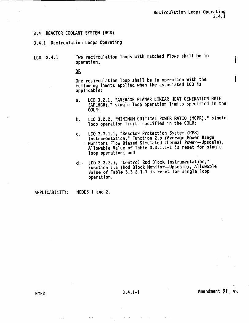
Recirculation Loops Operating 3.4.1
3.4 REACTOR COOLANT SYSTEM (RCS)
3.4.1 Recirculation Loops Operating
LCO 3.4.1 Two recirculation loops with matched flows shall be in
operation,
OR
One recirculation loop shall be in operation with the following limits applied when the associated LCO is applicable:
a. LCO 3.2.1, "AVERAGE PLANAR LINEAR HEAT GENERATION RATE (APLHGR)," single loop operation limits specified in the COLR;
b. LCO 3.2.2, "MINIMUM CRITICAL POWER RATIO (MCPR)," single loop operation limits specified in the COLR;
c. LCO 3.3.1.1, "Reactor Protection System (RPS) Instrumentation," Function 2.b (Average Power Range Monitors Flow Biased Simulated Thermal Power-Upscale), Allowable Value of Table 3.3.1.1-1 is reset for single loop operation; and
d. LCO 3.3.2.1, "Control Rod Block Instrumentation," Function 1.a (Rod Block Monitor-Upscale), Allowable Value of Table 3.3.2.1-1 is reset for single loop operation.
APPLICABILITY: MODES I and 2.
Amendment ý!, 923.4.1-1NMP2
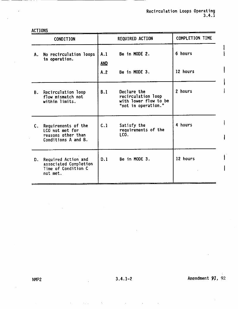
Recirculation Loops Operating 3.4.1
ACTIONS
CONDITION REQUIRED ACTION COMPLETION TIME
A. No recirculation loops A.1 Be in MODE 2. 6 hours in operation.
AND
A.2 Be in MODE 3. 12 hours
B. Recirculation loop B.1 Declare the 2 hours flow mismatch not recirculation loop within limits, with lower flow to be
"not in operation."
C. Requirements of the C.1 Satisfy the 4 hours LCO not met for requirements of the reasons other than LCO. Conditions A and B.
D. Required Action and D.1 Be in MODE 3. 12 hours associated Completion Time of Condition C not met.
Amendment P1, 923.4.1-2NMP2
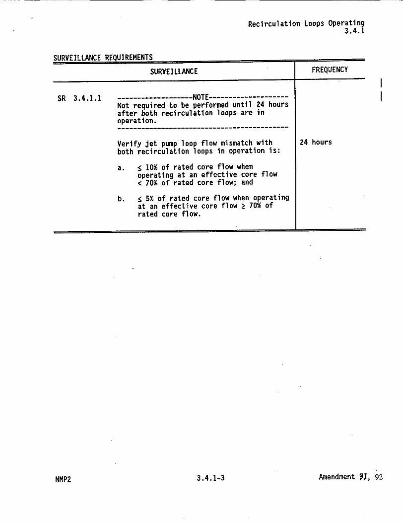
Recirculation Loops Operating 3.4.1
SURVEILLANCE REQUIREMENTS
SURVEILLANCE FREQUENCY
SR 3.4.1.1 ------------------ NOTE ---------------Not required to be performed until 24 hours after both recirculation loops are in operation. ---------------------------------------
Verify jet pump loop flow mismatch with 24 hours both recirculation loops in operation is:
a. • 10% of rated core flow when operating at an effective core flow < 70% of rated core flow; and
b. < 5% of rated core flow when operating at an effective core flow > 70% of rated core flow.
Amendment P1, 92
I I
3.4.1-3NMP2
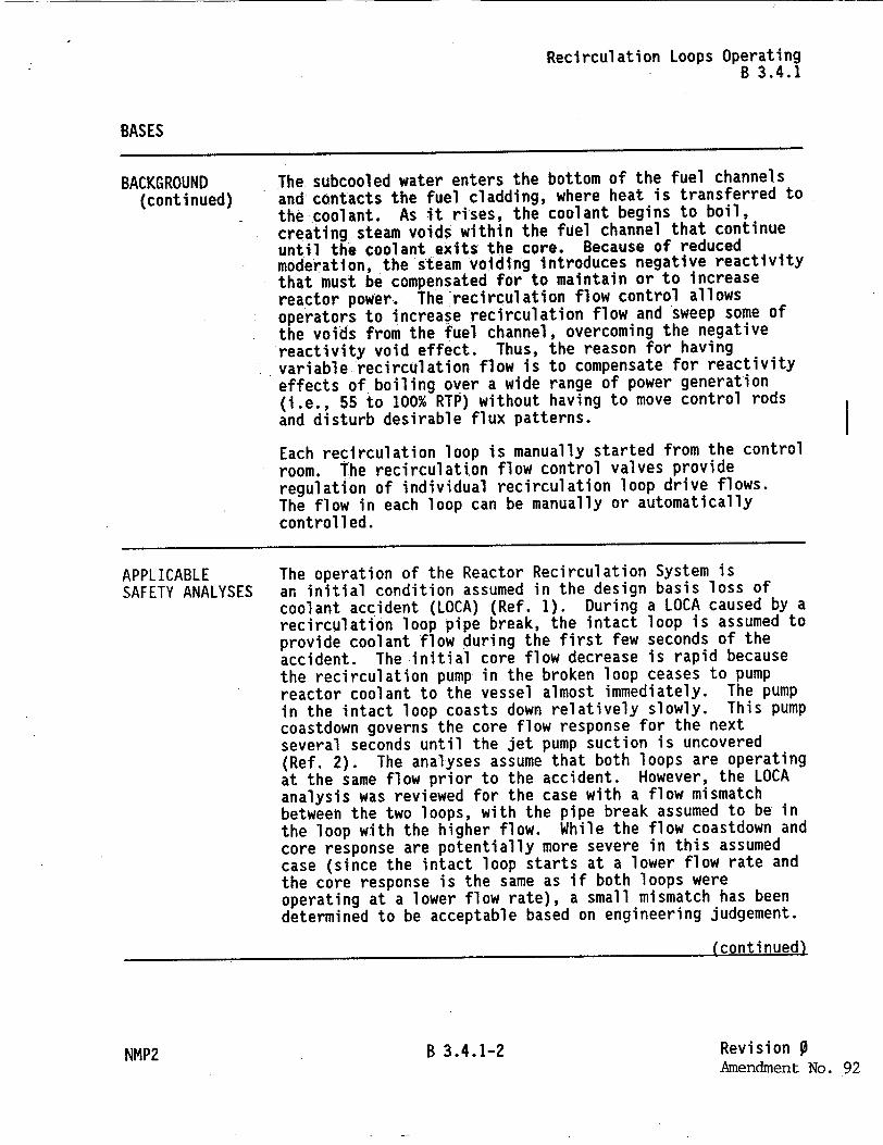
Recirculation Loops Operating B 3.4.1
BASES
BACKGROUND (continued)
The subcooled water enters the bottom of the fuel channels and contacts the fuel cladding, where heat is transferred to the coolant. As it rises, the coolant begins to boil, creating steam voids within the fuel channel that continue until the coolant exits the core. Because of reduced moderation, the steam voiding introduces negative reactivity that must be compensated for to maintain or to increase reactor power. The'recirculation flow control allows operators to increase recirculation flow and sweep some of the voids from the fuel channel, overcoming the negative reactivity void effect. Thus, the reason for having variable recirculation flow is to compensate for reactivity effects of boiling over a wide range of power generation (i.e., 55 to 100% RTP) without having to move control rods and disturb desirable flux patterns.
Each recirculation loop is manually started from the control room. The recirculation flow control valves provide regulation of individual recirculation loop drive flows. The flow in each loop can be manually or automatically controlled.
APPLICABLE SAFETY ANALYSES
The operation of the Reactor Recirculation System is an initial condition assumed in the design basis loss of coolant accident (LOCA) (Ref. 1). During a LOCA caused by a recirculation loop pipe break, the intact loop is assumed to provide coolant flow during the first few seconds of the accident. The initial core flow decrease is rapid because the recirculation pump in the broken loop ceases to pump reactor coolant to the vessel almost immediately. The pump in the intact loop coasts down relatively slowly. This pump coastdown governs the core flow response for the next several seconds until the jet pump suction is uncovered (Ref. 2). The analyses assume that both loops are operating at the same flow prior to the accident. However, the LOCA analysis was reviewed for the case with a flow mismatch between the two loops, with the pipe break assumed to be in the loop with the higher flow. While the flow coastdown and core response are potentially more severe in this assumed case (since the intact loop starts at a lower flow rate and the core response is the same as if both loops were operating at a lower flow rate), a small mismatch has been determined to be acceptable based on engineering judgement.
(conti nued)
B 3.4.1-2 Revision 0 Amendment No. 92
I
NMP2
Recirculation Loops Operating B 3.4.1
BASES
APPLICABLE The recirculation system is also assumed to have sufficient SAFETY ANALYSES flow coastdown characteristics to maintain fuel thermal
(continued) margins during abnormal operational transients (Ref. 3), which are analyzed in Chapter 15 of the USAR.
A plant specific LOCA analysis has been performed assuming only-one operating recirculation loop. This analysis has demonstrated that, in the event of a LOCA caused by a pipe break in the operating recirculation loop, the Emergency Core Cooling System response will provide adequate core cooling, provided the APLHGR requirements are modified accordingly (Ref. 4).
The transient analyses in Chapter 15 of the USAR have also been performed for single recirculation loop operation (Ref. 4) and demonstrate sufficient flow coastdown characteristics to maintain fuel thermal margins during the abnormal operational transients analyzed provided the MCPR requirements are modified. During single recirculation loop operation, modification to the Reactor Protection System average power range monitor (APRM) and the Rod Block Monitor Allowable Values is also required to account-for the different relationships between recirculation drive flow and reactor core flow. The APLHGR and MCPR limits for single loop operation are specified in the COLR. The APRM Flow Biased Simulated Thermal Power-Upscale Allowable Value is in LCO 3.3.1.1, "Reactor Protection System (RPS) Instrumentation." The Rod Block Monitor-Upscale Allowable Value is in LCO 3.3.2.1, "Control Rod Block Instrumentation."
Recirculation loops operating satisfies Criterion 2 of Reference 5.
LCO Two recirculation loops are normally required to be in operation with their flows matched within the limits specified in SR 3.4.1.1 to ensure that during a LOCA caused by a break of the piping of one recirculation loop the assumptions of the LOCA analysis are satisfied. Alternatively, with only one recirculation loop in operation, modifications to the required APLHGR limits (LCO 3.2.1, "AVERAGE PLANAR LINEAR HEAT GENERATION RATE (APLHGR)"), MCPR limits (LCO 3.2.2, "MINIMUM CRITICAL POWER RATIO (MCPR)"), APRM Flow Biased Simulated Thermal Power-Upscale Allowable Value (LCO 3.3.1.1), and the Rod
(continued)
NMP2 B 3.4.1-3 Revision 9 Amendment No. 92
Recirculation Loops Operating B 3.4.1
BASES
LCO Block Monitor-Upscale Allowable Value (LCO 3.3.2.1) must (continued) be applied to allow continued operation consistent with the
assumptions of Reference 4.
APPLICABILITY In MODES 1 and 2, requirements for operation of the Reactor Coolant Recirculation System are necessary since there is considerable energy in the reactor core and the limiting design basis transients and accidents are assumed to occur.
In MODES 3, 4, and 5, the consequences of an accident are reduced and the coastdown characteristics of the recirculation loops are not important.
ACTIONS A.1 and A.2
With no recirculation loops in operation, the unit is required to be brought to a MODE in which the LCO does not apply. To achieve this status, the plant must be brought to MODE 2 within 6 hours and to MODE 3 within 12 hours. In this condition, the recirculation loops are not required to be operating because of the reduced severity of DBAs and transients and minimal dependence on the recirculation loop cGastdown characteristics. The allowed Completion Times are reasonable, based on operating experience, to reach the required plant conditions from full power conditions in an orderly manner and without challenging plant systems.
B.1 and C.1
With both recirculation loops operating but the flows not matched, the flows must be matched within 2 hours. If matched flows are not restored, the recirculation loop with lower flow must be declared "not in operation," as required by Required Action B.]. This Required Action does not require tripping the recirculation pump in the lowest flow loop when the mismatch between total jet pump flows of the two loops is greater than the required limits. However, in cases where large flow mismatches occur, low flow or reverse flow can occur in the low flow loop jet pumps, causing vibration of the jet pumps. If zero or reverse flow is detected, the condition should be alleviated by changing flow control valve position to re-establish forward flow or by tripping the pump.
(continued)
NMP2 B 3.4.1-4 Revision 9Amendment No. 92
Recirculation Loops Operating B 3.4.1
BASES
ACTIONS B.1 and C.1 (continued)
With the requirements of the LCO not met for reasons other than Condition A and B (e.g. one loop is "not in operation"), the recirculation loops must be restored to operation with matched flows within 4 hours. A recirculation loop is considered not in operation when the pump in that loop is idle or when the mismatch between total jet pump flows of the two loops is greater than required limits for greater than 2 hours (i.e. Required Action B.1 has been taken). Should a LOCA occur with one recirculation loop not in operation, the core flow coastdown and resultant core response may not be bounded by the LOCA analyses. Therefore, only a limited time is allowed to restore the inoperable loop to operating status.
Alternatively, if the single loop requirements of the LCO are applied to the APLHGR and MCPR operating limits and RPS and RBM Allowable Values, operation with only one recirculation loop would satisfy the requirements of the LCO and the initial conditions of the accident sequence.
The 2 hour and 4 hour Completion Times are based on the low probability of an accident occurring during this-time period, on a reasonable time to complete the Required Action, and on frequent core monitoring by operators allowing abrupt changes in core flow conditions to be quickly detected.
D.1
If the Required Action and associated Completion Time of Condition C is not met, the unit is required to be brought to a MODE in which the LCO does not apply. To achieve this status, the plant must be brought to MODE 3 within 12 hours. In this condition, the recirculation loops are not required to be operating because of the reduced severity of DBAs and minimal dependence on the recirculation loop coastdown characteristics. The allowed Completion Time of 12 hours is reasonable, based on operating experience, to reach MODE 3 from full power conditions in an orderly manner and without challenging plant systems.
(continued)
NMP2 B 3.4.1-5 Revision 0 Amendment No. 92
Recirculation Loops Operating B 3.4.1
BASES (continued)
SURVEILLANCE REQUIREMENTS
SR 3.4.1.1
This SR ensures the recirculation loop flows are within the allowable limits for mismatch. At low core flow (i.e., effective core flow < 70% of rated core flow), the APLHGR and MCPR'requirements provide larger margins to the fuel cladding integrity Safety Limit such that the potential adverse effect of early boiling transition during a LOCA is reduced. A larger flow mismatch can therefore be allowed when effective core flow is < 70% of rated core flow. The jet pump loop flow, as used in this Surveillance, is the summation of the flows from all of the jet pumps associated with a single recirculation loop. The effective core flow shall be calculated by assuming both loops are at the smaller value of the two jet pump loop flows.
The mismatch is measured in terms of percent of rated core flow. If the flow mismatch exceeds the specified limits, the loop with the lower flow is considered not in operation. This SR is not required when both loops are not in operation since the mismatch limits are meaningless during single loop or natural circulation operation. The Surveillance must be performed within 24 hours after both loops are in operation. The 24 hour Frequency is consistent with the Frequency for jet pump OPERABILITY verification and has been shown by operating experience to be adequate to detect off normal jet pump loop flows in a timely manner.
REFERENCES I. USAR, Section 6.3 and Appendix A Section 6.
2. USAR, Section 6.3.3.7.
3. USAR, Section 5.4.1.3.
4. USAR Chapter 15B.
5. 10 CFR 50.36(c)(2)(ii).
B 3.4.1-6 Revision 0 Amendment No. 92
NMP2
I I
I I
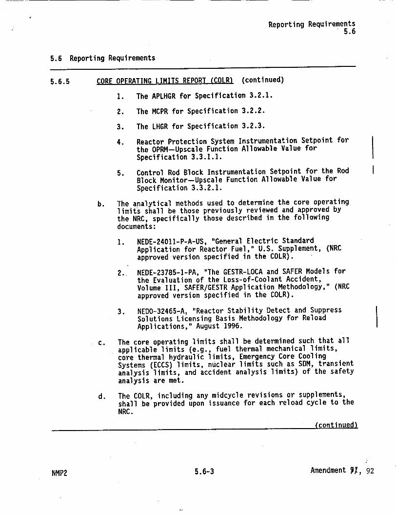
Reporting Requirements 5.6
5.6 Reporting Requirements
5.6.5 CORE OPERATING LIMITS REPORT (COLR) (continued)
1. The APLHGR for Specification 3.2.1.
2. The MCPR for Specification 3.2.2.
3. The LHGR for Specification 3.2.3.
4. Reactor Protection System Instrumentation Setpoint for the OPRM-Upscale Function Allowable Value for Specification 3.3.1.1.
5. Control Rod Block Instrumentation Setpoint for the Rod Block Monitor-Upscale Function Allowable Value for Specification 3.3.2.1.
b. The analytical methods used to determine the core operating limits shall be those previously reviewed and approved by the NRC, specifically those described in the following documents:
1. NEDE-24011-P-A-US, "General Electric Standard Application for Reactor Fuel," U.S. Supplement, (NRC approved version specified in the COLR).
2. NEDE-23785-1-PA, "The GESTR-LOCA and SAFER Models for the Evaluation of the Loss-of-Coolant Accident, Volume III, SAFER/GESTR Application Methodology," (NRC approved version specified in the COLR).
3. NEDO-32465-A, "Reactor Stability Detect and Suppress Solutions Licensing Basis Methodology for Reload Applications," August 1996.
c. The core operating limits shall be determined such that all applicable limits (e.g., fuel thermal mechanical limits, core thermal hydraulic limits, Emergency Core Cooling Systems (ECCS) limits, nuclear limits such as SDM, transient analysis limits, and accident analysis limits) of the safety analysis are met.
d. The COLR, including any midcycle revisions or supplements, shall be provided upon issuance for each reload cycle to the NRC.
(continued)
Amendment 91, 925.6-3
I
NMP2
Reporting Requirements 5.6
5.6 Reporting Requirements (continued)
5.6.6 Post Accident Monitoring (PAM) Instrumentation Report
When a report is required by Condition B or F of LCO 3.3.3.1, "Post Accident Monitoring (PAM) Instrumentation," a report shall be submitted within the following 14 days. The report shall outline the preplanned alternate method of monitoring, the cause of the inoperability, and the plans and schedule for restoring the instrumentation channels of the Function to OPERABLE status.
Amendment 91, 925.6-4NMP2
UNITED STATES NUCLEAR REGULATORY COMMISSION
WASHINGTON, D.C. 20555-0001
SAFETY EVALUATION BY THE OFFICE OF NUCLEAR REACTOR REGULATION
RELATED TO AMENDMENT NO. 92 TO FACILITY OPERATING LICENSE NO. NPF-69
NIAGARA MOHAWK POWER CORPORATION
NINE MILE POINT NUCLEAR STATION, UNIT NO. 2
DOCKET NO. 50-410
1.0 INTRODUCTION
By letter dated October 25, 1999, Niagara Mohawk Power Corporation (the licensee) submitted a request -to amend the Technical Specifications (TS) for the Nine Mile Point, Unit 2 (NMP2). The proposed changes will permit activation of the Oscillation Power Range Monitor (OPRM) system. The NRC staff and the licensee discussed the submittal during a conference call on January 7, 2000. As a result, the licensee submitted supplemental information by letters dated February 2 and 7, 2000. The supplemental information was not outside of the scope of the original October 25, 1999, amendment request.
2.0 BACKGROUND
An event at LaSalle Unit 2 in 1988 showed that under certain conditions power oscillations can result in conditions exceeding acceptable fuel design limits. The Boiling Water Reactor (BWR) Owners Group (BWROG) proposed several long-term solutions to this thermal-hydraulic instability in Topical Reports NEDO-31960, "BWR Owners Group Long-Term Stability Solutions Licensing Methodology" datedJune 1991 and NEDO-31960, Supplement 1, dated March 1992. By letter dated July 12, 1993, the staff approved four of the six long-term solutions as acceptable. One of the proposed solutions is Option Ill, which uses Local Power Range Monitor (LPRM) signals to detect power oscillations and takes automatic protective actions to suppress the power oscillations before safety margins are compromised. The staff-approved report NEDO-31960-A, Supplement 1, Class 1 (non-proprietary), was published in November 1995.
By letter dated July 11,1994, the NRC staff issued Generic Letter 94-02, "Long-Term Solutions and Upgrade of Interim Operating Recommendations for Thermal-Hydraulic Instabilities in Boiling Water Reactors," requesting BWR licensees to submit their plans for long-term solutions of the thermal-hydraulic instabilities including implementation schedule.
By letter dated November 8, 1994, the licensee selected Option III (delineated in NEDO-31960), replacing the analog Average Power Range Monitor (APRM) system with the General Electric (GE) digital, Nuclear Measurement Analysis and Control (NUMAC) Power Range Neutron Monitor (PRNM) system. The NUMAC-PRNM system monitors groups of LPRM signals and,
-2-
together with the OPRM, initiates a reactor scram upon detection of neutron flux oscillations caused by thermal-hydraulic instability.
By letter dated April 4, 1995, General Electric (GE) submitted Licensing Topical Report NEDC32410P, "Nuclear Measurement Analysis and Control Power Range Monitor (NUMAC PRNM) Retrofit Plus Option III Stability Trip Function." Appendix H of this report, "Sample Markup of Tech Specs," provides examples of GE-recommended TS changes a licensee may use when submitting a plant-specific license amendment to reflect the use of the PRNM. By letter dated September 5, 1995, the NRC staff approved this report. The NRC-approved report NEDC32410P-A, Class IIl (proprietary), was published in October 1995.
By letter dated May 24, 1995, GE submitted Supplement 1 to Topical Report NEDC-32410P. This report clarified a number of issues related to the APRM and proposed TS for the OPRM. By letter dated August 15, 1997, the staff approved this report. The NRC-approved report NEDC-3241OP-A, Supplement 1, Class 3, was published in November 1997.
By letter dated October 31, 1997, as supplemented by letter dated February 3, 1998, the licensee proposed changes to the NMP2 TS to permit installation of the NUMAC-PRNM with provision for the OPRM function to be monitored during the first fuel cycle after installation of the NUMAC-PRNM. This monitoring of the OPRM was intended to ensure that the OPRM algorithms perform according to the design specification prior to using the OPRM for trip operation. On March 31, 1998,the NRC staff issUed Amendment No. 80 approving the TS changes; the related plant modifications were implemented by the licensee during refueling outage (RFO) 6. Since RFO6 the OPRM has been operated in indication mode only and plant personnel have collected the necessary system data.
By letter dated October 25, 1999, the licensee requested a TS amendment that will enable the OPRIV to activate the Reactor Protection System (.RPS) upon detection of excessive neutron flux oscillation from thermal-hydraulic instability. The licensee grouped the proposed TS changes as follows:
1. TS Table 2.2.1-1, RPS Instrument Setpoints and Associated Bases
2. TS Table 3.3.1-1, RPS Instrumentation, Associated Table Notations and Actions, and Footnotes * and ** to LCO 3.3.1 and Associated Bases.
3. Surveillance Requirements (SR) 4.3.1.2, RPS Logic System Functional Tests
4. TS 4.3.1.3, RPS Response Times
5. TS Table 4.3.1.1-1, RPS Instrumentation Surveillance Requirements
6. TS 3.4.1, Recirculation System and Associated Bases
7. TS 6.9.1.9, Core Operating Limits Report
By letter dated February 2, 2000, the licensee proposed to change the operating condition in Action 10, TS Table 3.3.1-1, from Hot Shutdown to Startup. By letter dated February 7, 2000, the licensee provided pages in the Improved Technical Specifications format (the NMP2 TS

-3-
was converted to this format by Amendment No. 91) with no change in technical content from the pages provided by the'letters of October 25, 1999, and February 2, 2000.
3.0 DISCUSSION AND EVALUATION
3.1 OPRM in Monitoring Mode
As stated above in Section 2.0, the staff had previously approved the licensee to install the NUMAC-PRNM with provision for the OPRM function to be monitored during the first fuel cycle after installation of the NUMAC-PRNM. This monitoring of the OPRM was intended to ensure that the OPRM algorithms perform according to the design specification before using the OPRM as part of the trip instrumentation. The related plant modifications were accordingly implemented by the licensee during refueling outage (RFO) 6. Since RFO6 the OPRM has been operated in indication mode only, and plant personnel have collected the necessary system data. The collected data confirm that the OPRM performed as designed and approved, and is thus acceptable for use as part of the trip instrumentation. The following sections describe the associated TS changes that must occur in order to incorporate the OPRM as part of the trip instrumentation.
3.2 Changes to the TS
Except for TS 6.9.1.9 changes, the licensee's proposed changes are consistent, with minor exceptions, With the OPRM TS changes recommended by GE in Appendix H of the NRCapproved Topical Report NEDC-3241 0P-A, Supplement 1. Detailed staff review on the proposed TS changes follows. (Note that corresponding locations of the same information in the post-Amendment-No.-91 TS are denoted in italics.)
3.2.1. Table 2.2.1-1, RPS Instrument Setpoints and Associated Bases (Table 3.3.1.1-1, Reactor Protection System Instrumentation [RPS] and Associated Bases)
This group of changes will add OPRM Upscale, Functional Unit 2.f, to Table 2.2.1-1, referring to NMP2 Core Operating Limits Reports (COLR) for Trip Setpoint and Allowable Value. The staff accepts that reference to the COLR is a way to comply with the GE Sample Markups of OPRM TS, Appendix H of NEDC-3241 OP-A, Supplement 1. Further, Bases Section 2.2.1, BASES FOR LIMITING SAFETY SYSTEM SETTINGS, will also be changed to reflect this change. The proposed changes are acceptable to the staff because they follow the guidelines of NEDC-3241 OP-A, Supplement 1.
3.2.2. Table 3.3.1-1, RPS Instrumentation, Associated Table Notations and Actions, and Footnotes * and ** to LCO 3.3.1, and Associated Bases (Table 3:3.1.1-1, RPS Instrumentation, and Associated Bases)
This group of changes will add OPRM Upscale Function 2.f to this table, specifying:
a. Applicable Operational Conditions as Condition 1 with note m
b. Minimum number of Operable Channels Per Trip System as 3

-4-
c. Action 10 for Function 2.f
d. Notes * and ** in TS 3.3.1-1, Limiting Condition for Operation
e. Related BASES section 3/4.3.1
The markup in page H-1 0 of NEDC-3241 OP-A, Supplement 1, specifies Applicable Mode as > 25% RTP and provides justification in pages 8-8 and 8-9 of the report. The licensee's proposed change, which specifies Applicable Operational Conditions as 1 with note m, is more Conservative. Note m is worded differently from the GE OPRM TS markup in NEDC-324110P-A, Supplement 1, Appendix H, to emphasize that automatic enabling of the OPRM trip function is the primary focus for operability.
The proposed requirements for Minimum Operable Channels and Footnotes * and ** are in conformance with the markup in page H-10 of NEDC-32410P-A.
The modification proposed for Action 10 by letter dated February 2, 2000, to change from Hot Shutdown to Startup is in conformance with Action 4 specified for Functional Units 2.b, 2.c, and 5. At NMP2 the Hot Shutdown Condition is with Mode Switch in Shutdown position with Average Reactor Coorant Temperature above 200OF and the Startup Condition is with Mode Switch in Startup/Hot Standby position with any Average Reactor Coolant Temperature.
The proposed changes to the Bases for TS 3.3.1 reflect the above changes.
This group of changes are either in conformance with NEDC-32410P-A, Supplement 1, or if different, have sound technical bases as explained above. The staff finds this group of changes acceptable.
3.2.3. Surveillance Requirements (SR) 4.3.1.2, RPS Logic System Functional Tests (Table 3.3.1.1-1, RPS Instrumentation, and Bases of SR 3.3.1.1.14)
These changes are consistent with NEDC-3241 OP-A and similar to the requirements for APRM Function 2.e of SR 4.3.1.2, and are therefore acceptable.
3.2.4. TS 4.3.1.3, RPS Response Times (Table 3.3.1.1-1, RPS Instrumentation)
This change exempts the OPRM from response time testing, is similar to the requirements for other comparable APRM functions in the TS, and is in conformance with the guidelines of NEDC 3241OP-A, Volume 1, Page 8-27. This change is therefore acceptable.
3.2.5. Table 4.3.1.1-1, RPS Instrumentation Surveillance Requirement (Table 3.3.1.1-1, RPS Instrumentation, SRs 3.3.1.1.10, 3.3.1.1.13, 3.3.1.1.16 and Associated Bases)
This group of changes will add OPRM Upscale Function 2.f to Table 4.3.1.1-1 specifying:
-5-
a. Channel Check: D
b. Channel Functional Test: SA(q)
c. Channel Calibration: R(p)
d. Operational Conditions: 1(o)
E. Notes: o, p, and q
The daily (D) Channel Check is in conformance with Channel Checks for other APRM channels in the TS.
The Channel Functional Test will be performed semi-annually (SA) in conformance with other APRM channels in the TS. The note q will exclude testing of the software part of the system; the software part will be automatically tested by the self-test function of the OPRM.
The once-per-refueling (R) Channel Calibration is in conformance with Channel Calibration for other comparable APRM channels in the TS.
Note p states, "Calibration includes verification that the OPRM Upscale trip is not bypassed when APRM Simulated Thermal Power is > 30% and recirculation drive flow is < 60% of the rated recirculation drive flow. No test signal will be injected for the purpose of testing the algorithm. Calibration of the OPRM will consist of verification of OPRM upscale setpoints in the APRM instrument by the review of the "Show Parameters" display." This note conforms with the plant operating configuration.
Operational Condition 1 is in conformance with OPRM channel Operational Condition in Table 3.3.1-1. The footnote o has been worded to emphasize that automatic enabling of the OPRM trip function is the primary focus for operability.
The staff finds this group of changes acceptable on the basis that these changes impose surveillance requirements to assure operability of the OPRM.
3.2.6. TS 3.4.1, Recirculation System and Associated Bases (TS 3.4.1, Recirculation Loops Operating, and Associated Bases)
TS 3.4.1 provides certain restrictions on plant operation in the regions of potential thermal-hydraulic instability. With the OPRM fully functional these restrictions are not required any more. The licensee proposed to delete them. The staff agrees that the current restrictions are no longer needed when OPRM is fully implemented, and finds their deletion acceptable.
3.2.7 TS 6.9.1.9, Core Operating Limits Report (TS 5.6.5, Core Operating Limits Report)
Topical Report NEDO-32465-A, "Reactor Stability Defect and Suppress Solutions Licensing Basis Methodology for Reload Applications, August 1996," is added to this
-6-
section. This topical report was previously approved by the staff and is applicable to NMP2 core operating limits analyses. Therefore reference to this topical report is acceptable.
3.3 Summary of Evaluation
In summary, the staff finds that the licensee's proposed changes to permit implementation of the OPRM conforms with the previously approved GE Topical Reports. The proposed changes are also comparable and consistent with existing TS requirements on other APRM channels. Since the last refueling outage the licensee has been monitoring the OPRM system except for the trip functions which were disabled. The data obtained from such monitoring show that the OPRM performed as designed. Accordingly, the staff finds the proposed changes delineated above acceptable.
4.0 STATE CONSULTATION
In accordance with the Commission's regulations, a New York State official was notified of the proposed issuance of the amendment. The State official, Mr. Jack Spath, had no comments on the proposed amendment.
5.0 ENVIRONMENTAL CONSIDERATION
The amendment changes a requirement with respect to installation and use of a facility component located within the restricted area as defined in 10 CFR Part 20. The NRC staff has determined that the amendment involves no significant increase in the amounts, and no significant change'in the types, of any effluents that may be released offsite, and that there is no significant increase in individual or cumulative occupational radiation exposure. The staff has previously issued a proposed finding that the amendment involves no significant hazards consideration, and there has been no public comment on such finding (64 FR 67336). The licensee's supplemental information'dated February 2 and 7, 2000, was not outside of the scope of the Federal Register notice and did not change the staffs proposed no significant hazards consideration. Accordingly, the amendment meets the eligibility criteria for categorical exclusion set forth in 10 CFR 51.22(c)(9). Pursuant to 10 CFR 51.22(b) no environmental impact statement or environmental assessment need be prepared in connection with the issuance of the amendment.
6.0 CONCLUSION
The staff has concluded, based on the considerations discussed above, that: (1) there is reasonable assurance that the health and safety of the public will not be endangered by operation in the proposed manner, (2) such activities will be conducted in compliance with the Commission's regulations, and (3) the issuance of the amendment will not be inimical to the common defense and security or to the health and safety of the public.
Principal Contributors: S. Mazumdar, M. Waterman and P. Tam
Date: March 2, 2000