joystick pvres and pvrel technical information...sauer-danfoss mobile power and control systems –...
TRANSCRIPT

Joystick PVRES and PVREL
Technical Information

DKMH.PN.580.B1.02 • 50L0559 • Rev A • 03/2003
Electrical remote control levers Technical InformationContents
PVRES gEnERaL
PVRES accESSoRiES
PVREL gEnERaL
© 2003 Sauer-Danfoss. All rights reserved. Printed in EuropeSauer-Danfoss accepts no responsibility for possible errors in catalogs, brochures and other printed material. Sauer-Danfoss reserves the right to alter its products without prior notice. This also applies to products already ordered provided that such alterations aren’t in conflict with agreed specifications. All trademarks in this material are properties of their respective owners. Sauer-Danfoss and the Sauer-Danfoss logotype are trademarks of the Sauer-Danfoss Group.
Front cover illustrations: F300641, , F300642, F300141, F300142 drawing: 155B577
PVRES general .................................................................................................................................................. 3Characteristic ................................................................................................................................................... 4Electrical system ............................................................................................................................................. 4Technical data .................................................................................................................................................. 5Code numbers and weight ......................................................................................................................... 6Dimensions ....................................................................................................................................................... 6
PVRES accessories .......................................................................................................................................... 8Code numbers and weight ......................................................................................................................... 9Dimensions ....................................................................................................................................................... 9
PVREL general ................................................................................................................................................11Characteristics ...............................................................................................................................................12Electrical system ...........................................................................................................................................13Electrical system PVREL ..............................................................................................................................13Code numbers and weight .......................................................................................................................14Technical data ................................................................................................................................................14Dimensions .....................................................................................................................................................15

DKMH.PN.580.B1.02 • 50L0559 • Rev A • 03/2003
Electrical remote control levers Technical Information
PVRES can be used individually or with PVRES accessories built together to form a complete operating panel. PVRES is particularly suited to panel mounting and characterised by:• finger-tip control • small dimensions • low weight • built-in flow regulation• accessories such as emergency stop and lamps (see page 8)
PVRES is supplied with one or two potentiometers. It is thus possible to regulate one function, or two functions at the same time.
Two further adjustments per function are built into PVRES. Independently of each other, these limit the signal voltage (US) and thereby the flow from proportional valve ports A and B without the movement of the remote control lever being limited.The oil flow can be infinitely reduced down to 25% of maximum flow.
Instead of the proportional functions, PVRES can be supplied with built-in switches.The contact functions can be either normally “ON” or normally “OFF” in neutral position.
gEnERaL
Two PRoPoRTionaL funcTionS
fLowadjuSTmEnT
on-off funcTion
PVRES general

DKMH.PN.580.B1.02 • 50L0559 • Rev A • 03/2003
Electrical remote control levers Technical InformationCharacteristics and electrical system PVRES
chaRacTERiSTic
ELEcTRicaL SySTEm 2 proportional functionswithout using neutral position switch
2 proportional functions with the use of neutral position switch
Signal leads
Supply leads
E: Emergency stop
An emergency stop should be
built into all electrical systems
F: Lead from fault monitoring

5DKMH.PN.580.B1.02 • 50L0559 • Rev A • 03/2003
Electrical remote control levers Technical Information
ELEcTRicaL SySTEm conTinuEd
Electrical system and technical data PVRES
On-off-on function
Signal leads
Supply leads
E: Emergency stop
An emergency stop should be
built into all electrical systems
TEchnicaL daTa UDC 11- 30 UDCSupply voltage
Max. ripple 5%
Current consumption < 80 mA
Max. force 50 N [11.24 lbf ]
USOutput voltage (US)
UDC 0,25 → 0,75
USNeutral voltage (US)
UDC 0,5
Two parallel-
Output signal
Max. load connected PVEs
Min. load impedance
to 0,5 • UDC 6 kΩ
Signal current max. UDC = 12 V ±0,6 mA (resistive)
UDC = 24 V ±1,2 mA
Neutral position switch max. current UDC = 12 V 2 A
UDC = 24 V 1 A
UDC =12 V 0,7 AOn - off - on switch max. current
UDC = 24 V 0,35 A
Ambient temperature - 30 to + 60°C
Enclosure to IEC 529 Over mounting flange IP 44
Under mounting flange IP 23
PVRE and PVRET must be connected to supply voltage at the same point as PVE.
DKMH.PN.580.B1.02 • 50L0559 • Rev A • 03/2003
Electrical remote control levers Technical InformationCode numbers , weights and dimensions PVRES
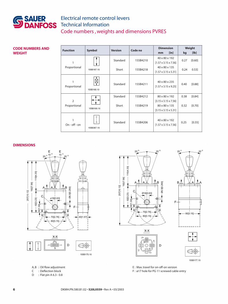
codE numbERS and wEighT
function Symbol Version code nodimension
mm [in]
weight
kg [lb]
1
Proportional
Standard
Short
155B4210
155B4218
40 x 80 x 192
[1.57 x 3.15 x 7.56]
40 x 80 x 135
[1.57 x 3.15 x 5.31]
0.27 [0.60]
0.24 0.53]
1
Proportional Standard 155B4211
40 x 80 x 235
[1.57 x 3.15 x 9.25]0.40 [0.88]
2
Proportional
Standard
Short
155B4212
155B4219
80 x 80 x 192
[3.15 x 3.15 x 7.56]
80 x 80 x 135
[3.15 x 3.15 x 5.31]
0.38 [0.84]
0.32 [0.70]
1
On - off - onStandard 155B4206
40 x 80 x 192
[1.57 x 3.15 x 7.56]0.25 [0.55]
dimEnSionS
A, B : Oil flow adjustmentC : Deflection blockD : Flat pin A 6.3 - 0.8
E : Max. travel for on-off-on versionF : ø17 hole for PG 11 screwed cable entry

DKMH.PN.580.B1.02 • 50L0559 • Rev A • 03/2003
Electrical remote control levers Technical InformationDimensions
dimEnSionS
A, B : Oil flow adjustmentC : Deflection blockD : Flat pin A 6.3 - 0.8E : Max. travel for on-off-on versionF : ø17 hole for PG 11 screwed cable entry
DKMH.PN.580.B1.02 • 50L0559 • Rev A • 03/2003
Electrical remote control levers Technical InformationElectrical remote control levers PVRES accessories
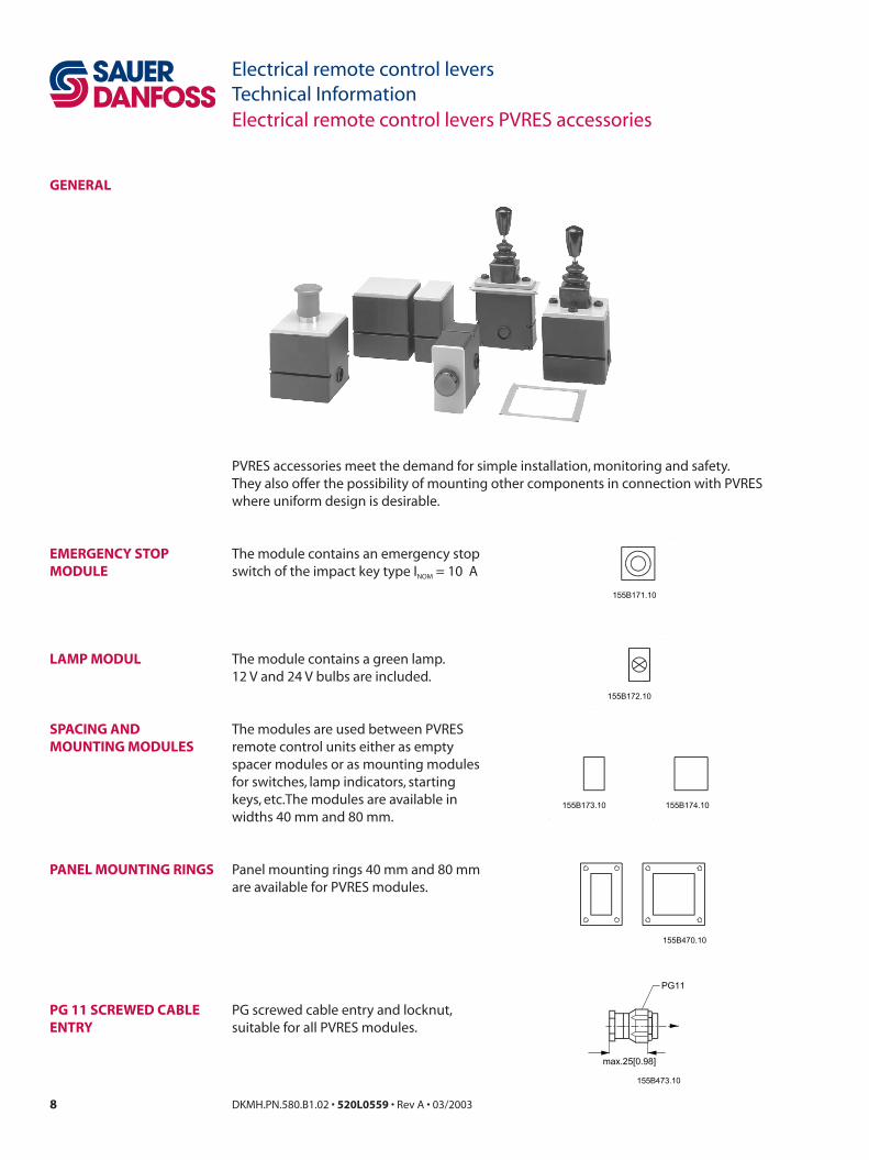
gEnERaL
PVRES accessories meet the demand for simple installation, monitoring and safety.They also offer the possibility of mounting other components in connection with PVRES where uniform design is desirable.
EmERgEncy SToP moduLE
LamP moduL
SPacing and mounTing moduLES
PanEL mounTing RingS
Pg 11 ScREwEd cabLE EnTRy
The module contains an emergency stop switch of the impact key type INOM = 10 A
The module contains a green lamp.12 V and 24 V bulbs are included.
The modules are used between PVRES remote control units either as empty spacer modules or as mounting modules for switches, lamp indicators, starting keys, etc.The modules are available in widths 40 mm and 80 mm.
Panel mounting rings 40 mm and 80 mm are available for PVRES modules.
PG screwed cable entry and locknut, suitable for all PVRES modules.

9DKMH.PN.580.B1.02 • 50L0559 • Rev A • 03/2003
Electrical remote control levers Technical InformationElectrical remote control levers PVRES accessories
codE numbERS and wEighT
Type code number dimension weight
mm [in] kg [lb]
Lamp module 155B4213 40 x 80 0,22 [0.48]
[1.57 x 3.15]
Emergency stop 155B4216 80 x 80 0,33 [0.73]
[3.15 x 3.15]
40 x 80
155B4214
[1.57 x 3.15] 0,15 [0.33]
Spacer and
mounting module
155B4215
80 x 80 0,18 [0.40]
[3.15 x 3.15]
Panel mounting plate 155B4876
60 x 100 [2.36 x 3.94] 0,04 [0.09]
155B4877 100 x 100 [3.94 x 3.94] 0,05 [0.11]
PG 11 screwed
cable entry 155B4875 0,01 [0.02]
dimEnSionS
10 DKMH.PN.580.B1.02 • 50L0559 • Rev A • 03/2003
Electrical remote control levers Technical InformationElectrical remote control levers PVRES accessories
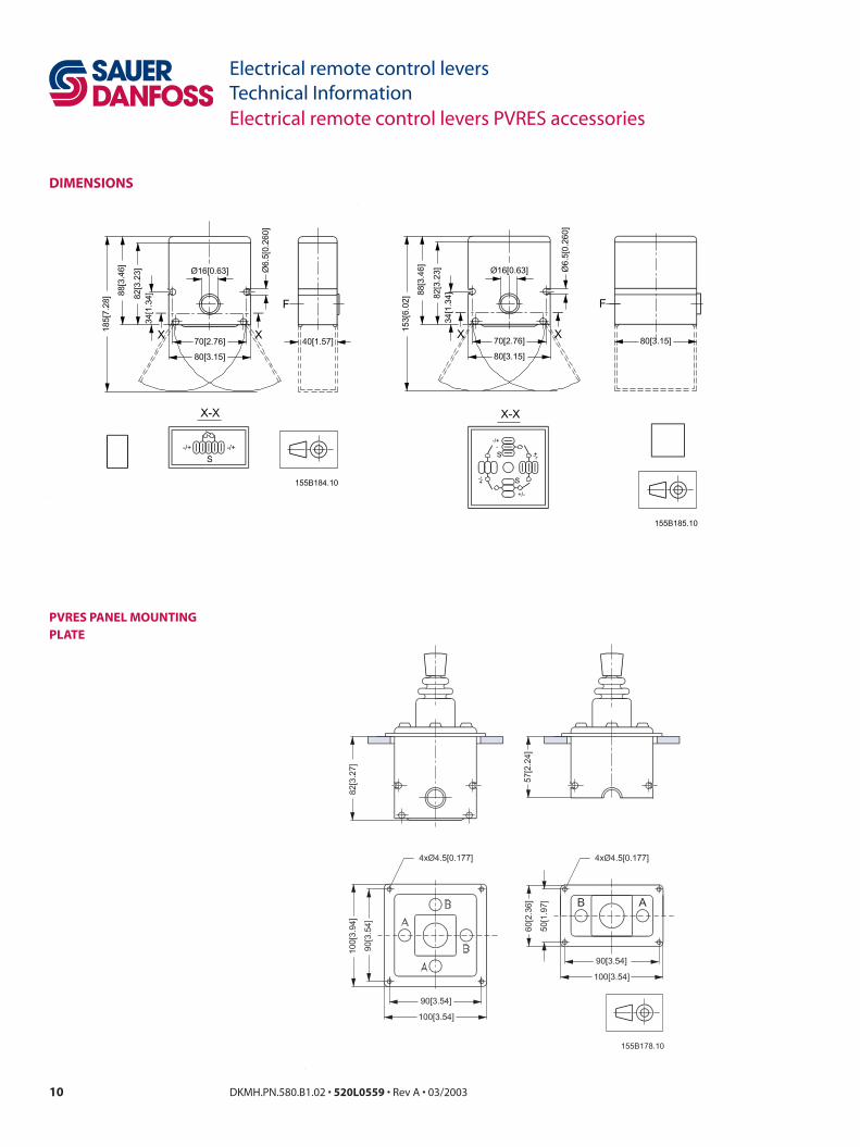
dimEnSionS
PVRES PanEL mounTing PLaTE

11DKMH.PN.580.B1.02 • 50L0559 • Rev A • 03/2003
Electrical remote control levers Technical Information
gEnERaL
PVREL general
PVREL is an electric remote control lever made in weather-resistant plastic.PVREL is for easy mounting in operating panels.PVREL is characterised by:
• IP 67 enclosure• low operating forces• robust construction• small dimensions
PRoPoRTionaL funcTion
VaRianTS
STandaRd
hoLd funcTion
nEuTRaL Lock
inSTaLLaTion
fLoaT PoSiTion
The PVREL remote control levers contains a potentiometer for the control of one proportional function.
The PVREL series contains four variants. These can be ordered with or without neutral position switch.
Spring-centred remote control lever. PVREL series basic model.
Spring-centred with hold function. The remote control lever functions as the basic model, but by rotating the top of the handle the centre position can be displaced and a constant control signal is given.The remote control lever can still be activated from its set centre position as normal, but when released will return to its set centre point.
Spring-centred with neutral position lock. The neutral position lock can be released by lifting the release ring under the handle.When the lever is returned to neutral position after manoeuvring, the neutral position lock will again engage.
Spring-centred with float position control. The remote control lever normally has proportional regulation in both directions, but with mechanical limitation in one direction to 3/4 of the normal activation range. The final 1/4 is used for float position control.
Access to the float position control is gained by lifting the release ring under the handle and moving the lever out to its float position. Here, on releasing the ring, the remote control lever becomes locked in float position.Return from float position is gained by again lifting the release ring and bringing the lever back to the proportional range.
Correctly placed, the PVREL can comply with the grade of enclosure IP 67 above the mounting flange.
1 DKMH.PN.580.B1.02 • 50L0559 • Rev A • 03/2003
Electrical remote control levers Technical InformationCharacteristics PVREL
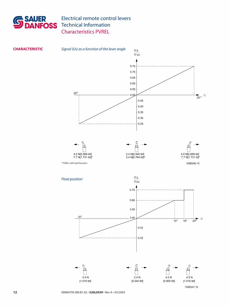
chaRacTERiSTic
* PVREL with hold function
Float position
Signal (Us) as a function of the lever angle

1DKMH.PN.580.B1.02 • 50L0559 • Rev A • 03/2003
Electrical remote control levers Technical Information
1 proportional functionwithout using neutral position switch
1 proportional function with the use of neutral position switch
Electrical system PVREL
ELEcTRicaL SySTEm
Signal leads Supply leadsE: Emergency stopF: Lead from fault monitoring

1 DKMH.PN.580.B1.02 • 50L0559 • Rev A • 03/2003
Electrical remote control levers Technical InformationTechnical data, code numbers and weight PVREL
codE numbERS and wEighT
functions Symbol code no. without code no. with weight
neutral position switch neutral position switch kg [lb]
Spring centred 155U2601 155U2605 0.32 [0.70]
With detent 155U2602 155U2606 0,32 [0.70]
With neutral
position look 155U2603 155U2607 0,36 [0.79]
For float position 155U2604 155U2608 0,36 [0.79]
For installation, all PVREL remote control levers are supplied with O-rings and bolt sets. The bottom cover is not included in the above mentioned code number.
accessories code no. weight
kg [lb]
Bottom cover , including PG-screwed connections
for IP 65 under the assembly flange 155U2600 0,025 [0,055]
TEchnicaL daTa UDC 11- 30 UDCSupply voltage
Max. ripple 5%
Current consumption < 80 mA
Max. force 100 N [22.5 lbf ]
USOutput voltage (US)
UDC 0,25 → 0,75
USNeutral voltage (US)
UDC 0,5
Two parallel-
Max. load
connected PVEs
Output signal Min. load impedance
to 0,5 • UDC 6 kΩ
Signal current max. UDC = 12 V ± 0,6 mA
UDC = 24 V ± 1,2 mA
Neutral position switch max. current UDC = 12 V 2 A
UDC = 24 V 1 A
Ambient temperature - 30 to + 60°C [-22 to 140°F]
Over mounting flange IP 67Enclosure to IEC 529 Under mounting flange
IP 65 with bottom cover 155U2600
PVREL must be connected to supply voltage at the same point as PVE.

15DKMH.PN.580.B1.02 • 50L0559 • Rev A • 03/2003
Electrical remote control levers Technical Information
dimEnSionS
Dimensions PVREL
F : Float positionA : Socket A 6,3-0,8M : Assembly aperture
Sauer-danfoss mobile Power and control Systems– market Leaders worldwide
Sauer-Danfoss is a comprehensive supplier providing complete systems to the global mobile market.
Sauer-Danfoss serves markets such as agriculture, construction, road building, material handling, municipal, forestry, turf care, and many others.
We offer our customers optimum solutions for their needs and develop new products and systems in close cooperation and partnership with them.
Sauer-Danfoss specializes in integrating a full range of system components to provide vehicle designers with the most advanced total system design.
Sauer-Danfoss provides comprehensive worldwide service for its products through an extensive network of Authorized Service Centers strategically located in all parts of the world.
Sauer-Danfoss (US) Company2800 East 13th StreetAmes, IA 50010, USAPhone: +1 515 239-6000, Fax: +1 515 239 6618
Sauer-Danfoss (Neumünster) GmbH & Co. OHGPostfach 2460, D-24531 NeumünsterKrokamp 35, D-24539 Neumünster, GermanyPhone: +49 4321 871-0, Fax: +49 4321 871 122
Sauer-Danfoss ApSDK-6430 Nordborg, DenmarkPhone: +45 7488 4444, Fax: +45 7488 4400
www.sauer-danfoss.com
ouR PRoducTS
Hydrostatic transmissions
Hydraulic power steering
Electric power steering
Electrohydraulic power steering
Closed and open circuit axial piston pumps and motors
Gear pumps and motors
Bent axis motors
Orbital motors
Transit mixer drives
Planetary compact gears
Proportional valves
Directional spool valves
Cartridge valves
Hydraulic integrated circuits
Hydrostatic transaxles
Integrated systems
Fan drive systems
Electrohydraulics
Micro-controllers and software
Electric motors and inverters
Joysticks and control handles
Displays
Sensors
DKMH.PN.580.B1.02 • 50L0559 • Rev A • 03/2003