journal of the electrochemical society 160 0013 …aminor.mse.berkeley.edu/publications_files/094...
TRANSCRIPT
A1380 Journal of The Electrochemical Society, 160 (9) A1380-A1383 (2013)0013-4651/2013/160(9)/A1380/4/$31.00 © The Electrochemical Society
Conductive Polymer and Silicon Composite Secondary Particlesfor a High Area-Loading Negative Electrode
Shidi Xun,a,∗ Bin Xiang,b,c,d Andrew Minor,b,c Vince Battaglia,a,∗ and Gao Liua,∗,z
aEnvironmental Energy Technologies Division, Lawrence Berkeley National Laboratory, Berkeley,California 94720, USAbNational Center for Electron Microscopy, Lawrence Berkeley National Laboratory, Berkeley, California 94720, USAcDepartment of Materials Science & Engineering, University of California, Berkeley, California 94720, USA
A conductive polymer and silicon nanoparticles were used to form elastic and porous micron-sized composite secondary particlesusing spray precipitation method. These composite secondary particles are used to fabricate a lithium-ion anode electrode. Althoughthe Si volume changes during charge and discharge process, the composite secondary particles retain their size during these processes,to maintain a stable electrode microstructure. This dimension stability leads to improved electrode cycling stability and enhancedrate performance.© 2013 The Electrochemical Society. [DOI: 10.1149/2.034309jes] All rights reserved.
Manuscript submitted May 1, 2013; revised manuscript received June 10, 2013. Published June 19, 2013.
Silicon (Si) material has high lithium-ion alloy capacity of4,200 mAh/g.1,2 At least a 3,580 mAh/g reversible lithium-ion capac-ity can be achieved via electrochemical process under the similar con-ditions of reversible lithiation and delithiation of graphite materials,3,4
which has only 372 mAh/g of lithium-ion capacity.5 The high capacitymakes Si an attractive material for the lithium-ion negative electrodeapplication, to further improve the energy density of rechargeablelithium-ion batteries.
However, the high lithium-ion capacity comes with a proportionalSi volume change, up to 300% volume expansion, from pure Si toLi4.4Si.3,4,6 In a conventional lithium-ion electrode, such as a graphiteor lithium cobalt oxide (LiCoO2)-based electrode, lithium-ion storageparticles are normally 1 to10 micrometer (μm)-sized particles.7 Thislarge volume change of Si induces high stress within the micron sizedSi particles, leading to mechanical breakdown of the particles.8–12
Nanosizing the Si particles can significantly reduce crack formation,resulting in better material integrity during the lithiation/delithiationprocess.13 Particle size preferably should be below 150 nm to signifi-cantly reduce crack formation.8,14
To make robust electrical connections to the nano-Si particles,a conductive polymer binder was developed. The binder combinesadhesion with electrical conduction to provide molecular-level elec-tronic connections between the Si nanoparticles and the conductivepolymer matrix.15 This approach has significantly enhanced the cy-cling stability of the Si electrode. However, the large volume changeof the Si nanoparticle during cycling has caused binder migration inthe electrode, leading to reduced pore sizes after just a few cycles.The gradual reduction of pore size seals off the ion-transport channelsin the porous electrode, resulting in capacity fade. This failure mech-anism is more pronounced as the electrode area loading of the activematerial and the thickness of electrode increases.16 A study based onthickness of the Si electrode has shown that area-specific capacity isinversely related to the cycling performance (Supplemental Figure 1).As the Si area loading in the electrode gets higher, the cycling perfor-mance decays significantly. This phenomenon is observed in all theSi-based and other active materials based electrodes, but more pro-nounced in Si-based electrodes. Both the ion-transport distance andtortuosity of the pores in the composite secondary electrode increaseas the electrode’s thickness increases. Therefore, lithium-ion diffusionis impeded with the increase of electrode thickness. Therefore, it isimportant to isolate the impact of Si volume change within micron-size domains, so as not to affect the overall electrode micro-structures.This is achieved by the following steps, as shown in Figure 1: First,form micron-size Si nanoparticle/conductive polymer composite sec-
∗Electrochemical Society Active Member.dPresent address: Department of Materials Science and Engineering, University ofScience and Technology of China, Hefei, Anhui Province 230026, China.
zE-mail: [email protected]
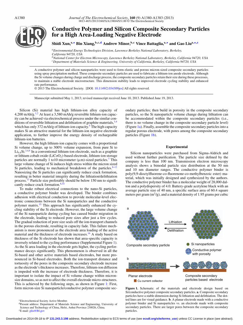
ondary particles; then build in porosity in the composite secondaryparticles, so the Si nanoparticle volume change during lithiation canbe accommodated within the composite secondary particles (i.e.,there is no volume change in the composite secondary particle level)(Figure 1a). Finally, assemble the composite secondary particles into aregular porous electrode, with pores among the composite secondaryparticles (Figure 1b).
Experimental
Silicon nanoparticles were purchased from Sigma-Aldrich andused without further purification. The particle size defined by thecompany is less than 100 nm. Transmission electron microscopyanalysis shows a bimodal particle size distribution at the 50 nmand 10 nm diameter ranges. The conductive polymer binder ispoly(9,9-dioctylfluorene-co-fluorenone-co-methylbenzoic ester) ma-terial, which was initially designed and synthesized by the authors.The conductive polymer binder has a molecular weight of 28,000 dal-ton and a polydispersity of 4.0. Battery-grade acetylene black with anaverage particle size of 40 nm, a specific surface area of 60.4 squaremeters per gram (m2/g), and a material density of 1.95 grams per cubic
Cu current collector
Delithiation
Lithiation
Si nanoparticles
Conductive polymer with porosity
Composite secondary particle
a
b
Planar electrode Composite secondary particles based electrode
Figure 1. Schematic of the materials and electrode design based onSi/conductive polymer composite secondary particles. a. Composite secondaryparticles have a stable dimension during Si lithiation and delithiation. The dot-ted lines are for visual guidance. b. A planar electrode made with a conductivepolymer binder and Si nanoparticles vs. an electrode made with compositesecondary particles. There are larger pores between the composite secondaryparticles.
) unless CC License in place (see abstract). ecsdl.org/site/terms_use address. Redistribution subject to ECS terms of use (see 131.243.3.198Downloaded on 2014-09-18 to IP
Journal of The Electrochemical Society, 160 (9) A1380-A1383 (2013) A1381
centimeter (g/cm3) was acquired from Denka Singapore Private Ltd.Chlorobenzene and methanol were purchased from Aldrich ChemicalCo. The 1 M LiPF6 in ethylene carbonate and fluorinated ethylenecarbonate (7:3 w/w) electrolyte was purchased from Novolyte Tech-nologies of BASF.
The Si/conductive polymer slurry and process for making the pla-nar electrode were previously reported.15 The slurry making processand the weight ratio of conductive polymer to Si in the compositeare described in detail in Supporting Information of reference.15 TheSi/conductive polymer composite secondary particle was made withthe sonication spray-precipitation process. The detailed instrumentmodels and setup can be found in the Supplemental Figure 2. TheSi/conductive polymer slurry was fed by syringe pump at the rate of0.1 liters per hour (L/h). The power of the ultrasonic atomizer wasset as 50%. The nanoporous spheres were sprayed to a large amountof methanol. Methanol is a non-solvent of the conductive polymer.After the particles were precipitated, methanol was decanted. Theproper amount of carboxylmethyl cellulose binder and carbon blackaqueous solution was added. Then the slurry was stirred for one hourwith a magnetic bar. The composition of the electrode is 10% car-boxymethyl cellulose (CMC), 10% acetylene black, and 80% Si com-posite secondary sphere. The uniform slurry was cast on copper foil.The thickness of electrodes was controlled by doctor blade gap toachieve the desired area capacity loading. The cross-section of com-posite secondary particles was acquired with Focused Ion Beam (FIB)milling. The cross section of electrodes was acquired by freezing theelectrode laminate in liquid nitrogen and folding the electrode lam-inate to break and expose the cross section. The SEM imaging wasperformed on the composite secondary particles surface and crosssection, and electrode surface and cross section. The FIB and SEMprocess were reported previously.17 Lithium metal counter electrodecoin cells were fabricated. The cell fabrication and electrochemicaltesting were performed according to the literature procedures.7,15
Results and Discussion
The composite secondary particle dimension and design are cru-cial for the success of this approach. The dimension of the compositesecondary particle has to allow the facile lithium-ion transport. Thisis determined experimentally by fabricating different thicknesses ofplanar electrodes and conducting rate and cycling tests of those elec-trodes. The planar Si electrode was fabricated by coating of the slurryof conductive polymer and Si nanoparticle directly on to Cu currentcollector, and drying at elevated temperature to form a electrode lami-
nate. The capacity decay of the planar electrode at different thicknessand Si loading is used to determine the critical dimension of this com-posite secondary system. The cycling performance is reported basedon a C/10 rate current density, which consumer electronics use for ahigh-energy battery system. The performance varies according to theC-rate. The planar laminate electrodes with thickness less than 10 μmshow stable cycling performance (Supplemental Figure 1a). The pla-nar electrode only allows lithium diffusion from the top to the bottomof the electrode. Therefore, the critical diameter for a spherical com-posite secondary particle is less than 20 μm, because the lithium-ioncan diffuse from any direction of the spherical surface. The capacityfades quickly if the engineered composite secondary particle diameteris larger than the critical dimensions, but if the composite secondaryparticles are too small, it will lose the benefit of accommodating vol-ume change of the primary Si nanoparticles.
A sonication spray-precipitation method was used to generatespherical composite secondary particles (Supplemental Figure 2).Controlled strength of ultrasound dispersion was used during thespray of Si/conductive polymer composite secondary slurry into a non-solvent of the conductive polymer to produce a spherical precipitate.By controlling the slurry solvent content and sonication strength, theaverage size and porosity of the composite secondary particle precip-itated can be controlled. The porosity within the composite secondaryparticles can provide dimensional stability in the composite secondaryparticle level, while the primary nanoparticles can freely expand andcontract. This dimensional stability of the composite secondary parti-cles maintains porosity among the composite secondary particles, toensure stable ion-transport properties in the electrode level. This willallow the fabrication of higher area loading of Si electrode.
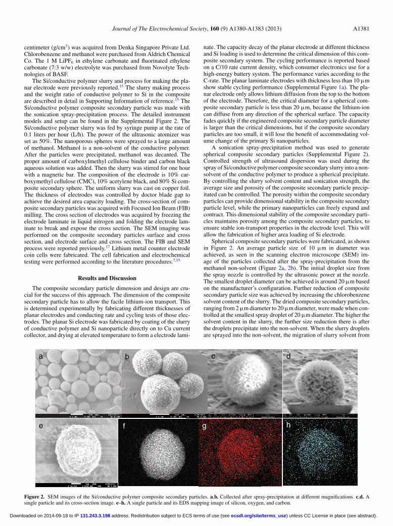
Spherical composite secondary particles were fabricated, as shownin Figure 2. An average particle size of 10 μm in diameter wasachieved, as seen in the scanning electron microscope (SEM) im-age of the particles collected after the spray-precipitation from themethanol non-solvent (Figure 2a, 2b). The initial droplet size fromthe spray nozzle is controlled by the ultrasonic power at the nozzle.The smallest droplet diameter can be achieved is around 20 μm basedon the manufacturer’s configuration. Further reduction of compositesecondary particle size was achieved by increasing the chlorobenzenesolvent content of the slurry. The dried composite secondary particles,ranging from 2 μm diameter to 20 μm diameter, were made when con-trolled at the smallest spray droplet of 20 μm diameter. The higher thesolvent content in the slurry, the further size reduction there is afterthe droplets precipitate into the non-solvent. When the slurry dropletsare sprayed into the non-solvent, the migration of slurry solvent from
a
e
d c b
h g f
Figure 2. SEM images of the Si/conductive polymer composite secondary particles. a,b. Collected after spray-precipitation at different magnifications. c,d. Asingle particle and its cross-section image. e–h. A single particle and its EDS mapping image of silicon, oxygen, and carbon.
) unless CC License in place (see abstract). ecsdl.org/site/terms_use address. Redistribution subject to ECS terms of use (see 131.243.3.198Downloaded on 2014-09-18 to IP
A1382 Journal of The Electrochemical Society, 160 (9) A1380-A1383 (2013)
0
0.2
0.4
0.6
0.8
1
0 500 1000 1500 2000 2500 3000
Pot
entia
l (V
)
Capacity (mAh/g)
0.1, 0.1 0.1, 0.5 0.1, 1 0.1, 2 0.1, 5
0
1
2
3
4
5
0 10 20 30
Cap
acity
(m
Ah/
cm2 )
Cycle Number
40 µm
78 µm
140 µm
160 µm
0
1000
2000
3000
4000
0 10 20 30 S
peci
fic C
apac
ity (
mA
h/g)
Cycle Number
40 µm
78 µm
140 µm
160 µm
a b c
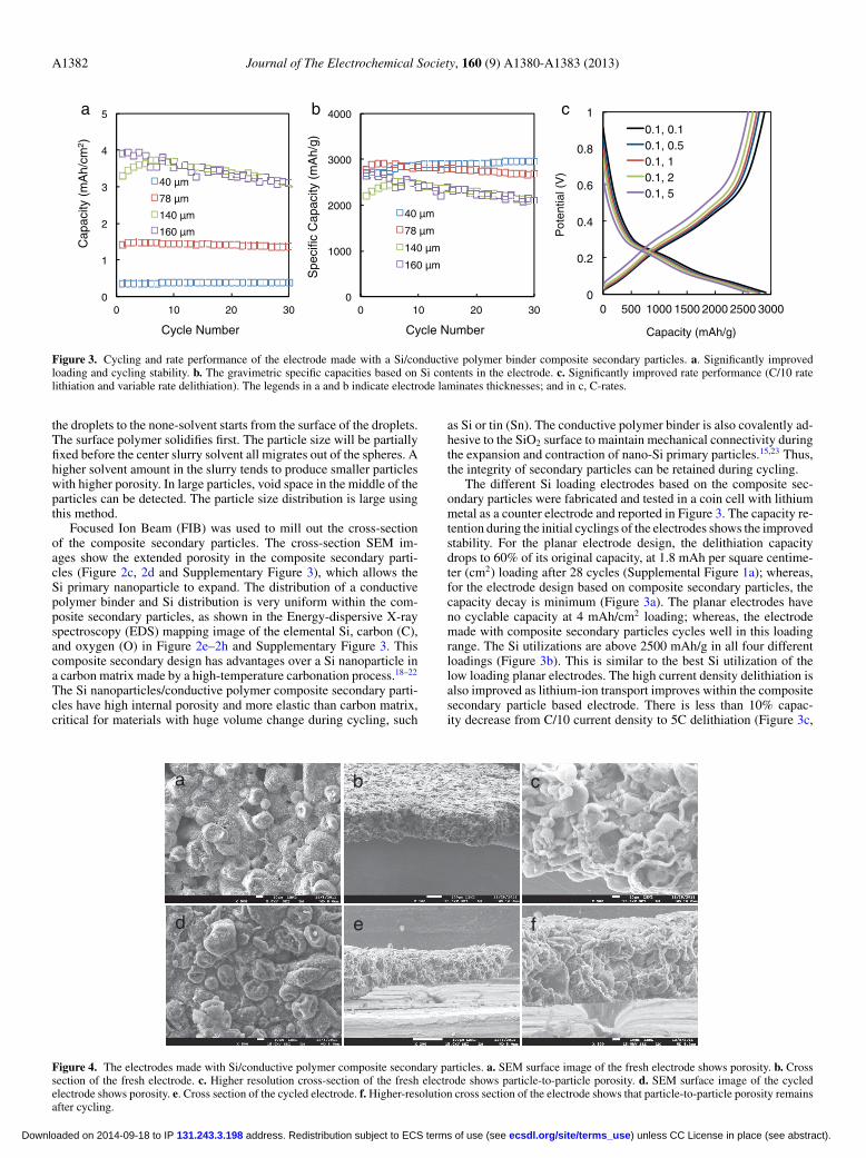
Figure 3. Cycling and rate performance of the electrode made with a Si/conductive polymer binder composite secondary particles. a. Significantly improvedloading and cycling stability. b. The gravimetric specific capacities based on Si contents in the electrode. c. Significantly improved rate performance (C/10 ratelithiation and variable rate delithiation). The legends in a and b indicate electrode laminates thicknesses; and in c, C-rates.
the droplets to the none-solvent starts from the surface of the droplets.The surface polymer solidifies first. The particle size will be partiallyfixed before the center slurry solvent all migrates out of the spheres. Ahigher solvent amount in the slurry tends to produce smaller particleswith higher porosity. In large particles, void space in the middle of theparticles can be detected. The particle size distribution is large usingthis method.
Focused Ion Beam (FIB) was used to mill out the cross-sectionof the composite secondary particles. The cross-section SEM im-ages show the extended porosity in the composite secondary parti-cles (Figure 2c, 2d and Supplementary Figure 3), which allows theSi primary nanoparticle to expand. The distribution of a conductivepolymer binder and Si distribution is very uniform within the com-posite secondary particles, as shown in the Energy-dispersive X-rayspectroscopy (EDS) mapping image of the elemental Si, carbon (C),and oxygen (O) in Figure 2e–2h and Supplementary Figure 3. Thiscomposite secondary design has advantages over a Si nanoparticle ina carbon matrix made by a high-temperature carbonation process.18–22
The Si nanoparticles/conductive polymer composite secondary parti-cles have high internal porosity and more elastic than carbon matrix,critical for materials with huge volume change during cycling, such
as Si or tin (Sn). The conductive polymer binder is also covalently ad-hesive to the SiO2 surface to maintain mechanical connectivity duringthe expansion and contraction of nano-Si primary particles.15,23 Thus,the integrity of secondary particles can be retained during cycling.
The different Si loading electrodes based on the composite sec-ondary particles were fabricated and tested in a coin cell with lithiummetal as a counter electrode and reported in Figure 3. The capacity re-tention during the initial cyclings of the electrodes shows the improvedstability. For the planar electrode design, the delithiation capacitydrops to 60% of its original capacity, at 1.8 mAh per square centime-ter (cm2) loading after 28 cycles (Supplemental Figure 1a); whereas,for the electrode design based on composite secondary particles, thecapacity decay is minimum (Figure 3a). The planar electrodes haveno cyclable capacity at 4 mAh/cm2 loading; whereas, the electrodemade with composite secondary particles cycles well in this loadingrange. The Si utilizations are above 2500 mAh/g in all four differentloadings (Figure 3b). This is similar to the best Si utilization of thelow loading planar electrodes. The high current density delithiation isalso improved as lithium-ion transport improves within the compositesecondary particle based electrode. There is less than 10% capac-ity decrease from C/10 current density to 5C delithiation (Figure 3c,
a c b
d f e
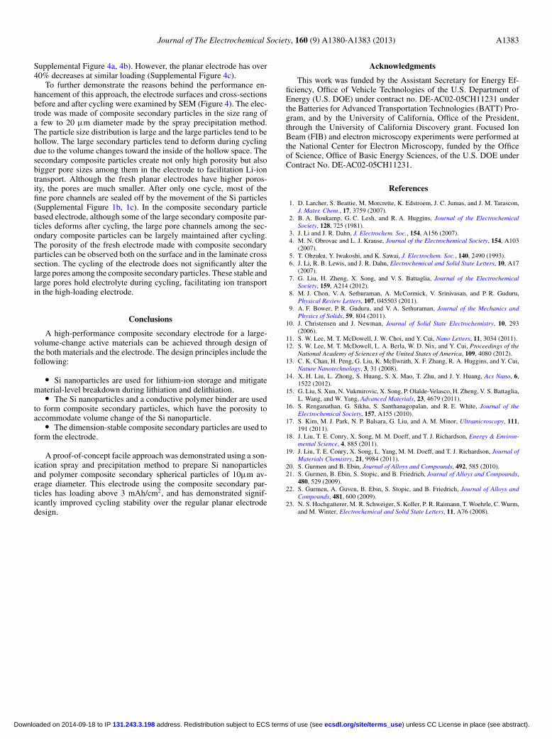
Figure 4. The electrodes made with Si/conductive polymer composite secondary particles. a. SEM surface image of the fresh electrode shows porosity. b. Crosssection of the fresh electrode. c. Higher resolution cross-section of the fresh electrode shows particle-to-particle porosity. d. SEM surface image of the cycledelectrode shows porosity. e. Cross section of the cycled electrode. f. Higher-resolution cross section of the electrode shows that particle-to-particle porosity remainsafter cycling.
) unless CC License in place (see abstract). ecsdl.org/site/terms_use address. Redistribution subject to ECS terms of use (see 131.243.3.198Downloaded on 2014-09-18 to IP
Journal of The Electrochemical Society, 160 (9) A1380-A1383 (2013) A1383
Supplemental Figure 4a, 4b). However, the planar electrode has over40% decreases at similar loading (Supplemental Figure 4c).
To further demonstrate the reasons behind the performance en-hancement of this approach, the electrode surfaces and cross-sectionsbefore and after cycling were examined by SEM (Figure 4). The elec-trode was made of composite secondary particles in the size rang ofa few to 20 μm diameter made by the spray precipitation method.The particle size distribution is large and the large particles tend to behollow. The large secondary particles tend to deform during cyclingdue to the volume changes toward the inside of the hollow space. Thesecondary composite particles create not only high porosity but alsobigger pore sizes among them in the electrode to facilitation Li-iontransport. Although the fresh planar electrodes have higher poros-ity, the pores are much smaller. After only one cycle, most of thefine pore channels are sealed off by the movement of the Si particles(Supplemental Figure 1b, 1c). In the composite secondary particlebased electrode, although some of the large secondary composite par-ticles deforms after cycling, the large pore channels among the sec-ondary composite particles can be largely maintained after cycling.The porosity of the fresh electrode made with composite secondaryparticles can be observed both on the surface and in the laminate crosssection. The cycling of the electrode does not significantly alter thelarge pores among the composite secondary particles. These stable andlarge pores hold electrolyte during cycling, facilitating ion transportin the high-loading electrode.
Conclusions
A high-performance composite secondary electrode for a large-volume-change active materials can be achieved through design ofthe both materials and the electrode. The design principles include thefollowing:
� Si nanoparticles are used for lithium-ion storage and mitigatematerial-level breakdown during lithiation and delithiation.
� The Si nanoparticles and a conductive polymer binder are usedto form composite secondary particles, which have the porosity toaccommodate volume change of the Si nanoparticle.
� The dimension-stable composite secondary particles are used toform the electrode.
A proof-of-concept facile approach was demonstrated using a son-ication spray and precipitation method to prepare Si nanoparticlesand polymer composite secondary spherical particles of 10μm av-erage diameter. This electrode using the composite secondary par-ticles has loading above 3 mAh/cm2, and has demonstrated signif-icantly improved cycling stability over the regular planar electrodedesign.
Acknowledgments
This work was funded by the Assistant Secretary for Energy Ef-ficiency, Office of Vehicle Technologies of the U.S. Department ofEnergy (U.S. DOE) under contract no. DE-AC02-05CH11231 underthe Batteries for Advanced Transportation Technologies (BATT) Pro-gram, and by the University of California, Office of the President,through the University of California Discovery grant. Focused IonBeam (FIB) and electron microscopy experiments were performed atthe National Center for Electron Microscopy, funded by the Officeof Science, Office of Basic Energy Sciences, of the U.S. DOE underContract No. DE-AC02-05CH11231.
References
1. D. Larcher, S. Beattie, M. Morcrette, K. Edstroem, J. C. Jumas, and J. M. Tarascon,J. Mater. Chem., 17, 3759 (2007).
2. B. A. Boukamp, G. C. Lesh, and R. A. Huggins, Journal of the ElectrochemicalSociety, 128, 725 (1981).
3. J. Li and J. R. Dahn, J. Electrochem. Soc., 154, A156 (2007).4. M. N. Obrovac and L. J. Krause, Journal of the Electrochemical Society, 154, A103
(2007).5. T. Ohzuku, Y. Iwakoshi, and K. Sawai, J. Electrochem. Soc., 140, 2490 (1993).6. J. Li, R. B. Lewis, and J. R. Dahn, Electrochemical and Solid State Letters, 10, A17
(2007).7. G. Liu, H. Zheng, X. Song, and V. S. Battaglia, Journal of the Electrochemical
Society, 159, A214 (2012).8. M. J. Chon, V. A. Sethuraman, A. McCormick, V. Srinivasan, and P. R. Guduru,
Physical Review Letters, 107, 045503 (2011).9. A. F. Bower, P. R. Guduru, and V. A. Sethuraman, Journal of the Mechanics and
Physics of Solids, 59, 804 (2011).10. J. Christensen and J. Newman, Journal of Solid State Electrochemistry, 10, 293
(2006).11. S. W. Lee, M. T. McDowell, J. W. Choi, and Y. Cui, Nano Letters, 11, 3034 (2011).12. S. W. Lee, M. T. McDowell, L. A. Berla, W. D. Nix, and Y. Cui, Proceedings of the
National Academy of Sciences of the United States of America, 109, 4080 (2012).13. C. K. Chan, H. Peng, G. Liu, K. McIlwrath, X. F. Zhang, R. A. Huggins, and Y. Cui,
Nature Nanotechnology, 3, 31 (2008).14. X. H. Liu, L. Zhong, S. Huang, S. X. Mao, T. Zhu, and J. Y. Huang, Acs Nano, 6,
1522 (2012).15. G. Liu, S. Xun, N. Vukmirovic, X. Song, P. Olalde-Velasco, H. Zheng, V. S. Battaglia,
L. Wang, and W. Yang, Advanced Materials, 23, 4679 (2011).16. S. Renganathan, G. Sikha, S. Santhanagopalan, and R. E. White, Journal of the
Electrochemical Society, 157, A155 (2010).17. S. Kim, M. J. Park, N. P. Balsara, G. Liu, and A. M. Minor, Ultramicroscopy, 111,
191 (2011).18. J. Liu, T. E. Conry, X. Song, M. M. Doeff, and T. J. Richardson, Energy & Environ-
mental Science, 4, 885 (2011).19. J. Liu, T. E. Conry, X. Song, L. Yang, M. M. Doeff, and T. J. Richardson, Journal of
Materials Chemistry, 21, 9984 (2011).20. S. Gurmen and B. Ebin, Journal of Alloys and Compounds, 492, 585 (2010).21. S. Gurmen, B. Ebin, S. Stopic, and B. Friedrich, Journal of Alloys and Compounds,
480, 529 (2009).22. S. Gurmen, A. Guven, B. Ebin, S. Stopic, and B. Friedrich, Journal of Alloys and
Compounds, 481, 600 (2009).23. N. S. Hochgatterer, M. R. Schweiger, S. Koller, P. R. Raimann, T. Woehrle, C. Wurm,
and M. Winter, Electrochemical and Solid State Letters, 11, A76 (2008).
) unless CC License in place (see abstract). ecsdl.org/site/terms_use address. Redistribution subject to ECS terms of use (see 131.243.3.198Downloaded on 2014-09-18 to IP