joshua zaiter - liberty university
TRANSCRIPT
PULSED POWER DESIGN AND APPLICATIONS 1
An Overview of Pulsed Power System Design and Applications
Joshua Zaiter
A Senior Thesis submitted in partial fulfillment
of the requirements for graduation
in the Honors Program
Liberty University
Spring 2021
PULSED POWER DESIGN AND APPLICATIONS
2
Acceptance of Senior Honors Thesis
This Senior Honors Thesis is accepted in partial
fulfillment of the requirements for graduation from the
Honors Program of Liberty University.
______________________________
Carl Pettiford, Ph.D.
Thesis Chair
______________________________
Kyung Kyoon Bae, Ph.D.
Committee Member
______________________________
David Schweitzer, Ph.D.
Assistant Honors Director
______________________________
Date
PULSED POWER DESIGN AND APPLICATIONS
3
Abstract
Pulsed power is the delivery of energy to a load in very short time frames. By reducing the time
component, massive instantaneous power magnitudes are achieved, scaling up to the high
terawatt range in some modern applications. The study of general system design and its
applications have great academic merit. By analyzing the structure and breakdown of such a
system, uses in various fields have been discovered, including cancer treatment and
manufacturing. Liberty hopes to gain access to this research field by replicating two existing
systems (with permission) and conducting tests to aid in societal progress. Results of high
voltage pulse generators with nanosecond fall times can be expected in the future.
PULSED POWER DESIGN AND APPLICATIONS
4
An Overview of Pulsed Power System Design and Applications
Introduction
The study of pulsed power and its applications is a growing topic of study within the
scientific and engineering communities, with state-of-the-art technologies and systems
revolutionizing processes in many different fields. The main goal behind the research conducted
for this thesis is to show typical system design and application benefits with the hope of
propagating interest in the field as well as bringing about a more advanced state of research at
Liberty University.
Background
Scientific Background
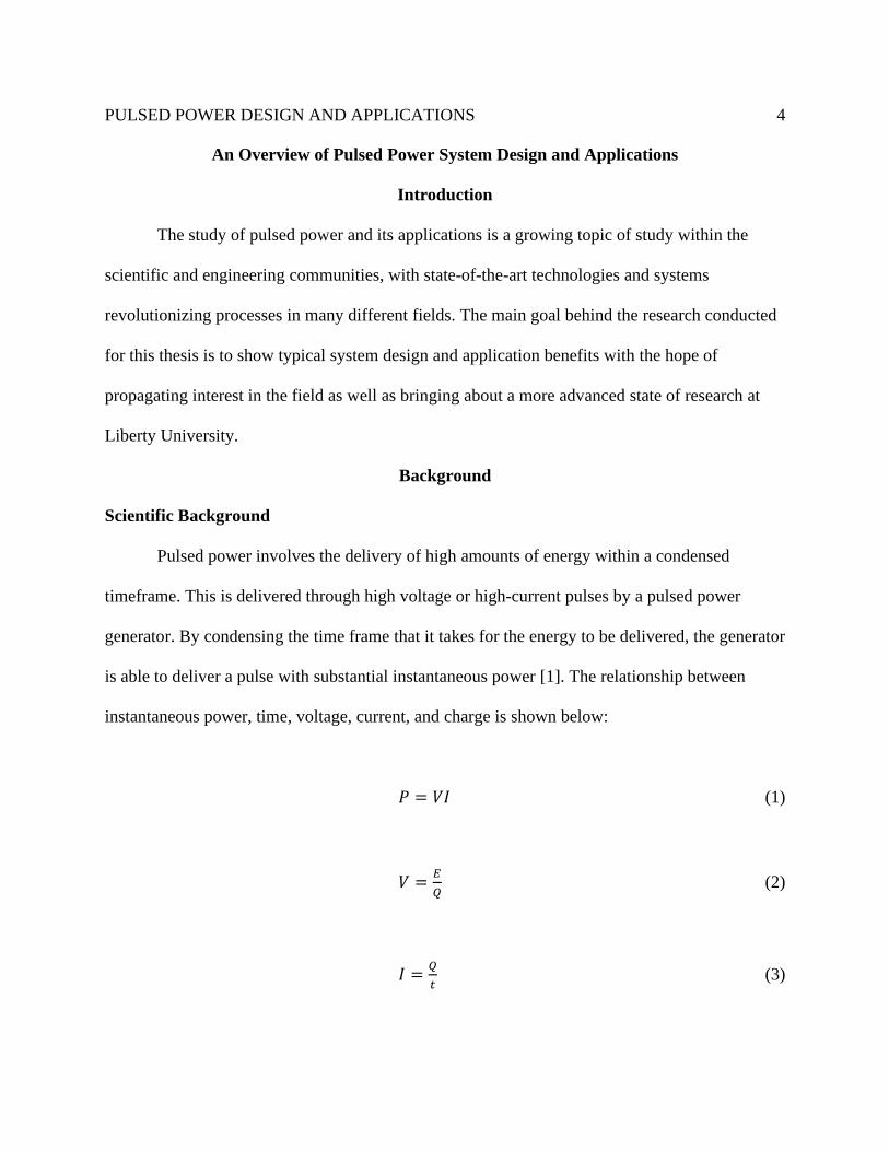
Pulsed power involves the delivery of high amounts of energy within a condensed
timeframe. This is delivered through high voltage or high-current pulses by a pulsed power
generator. By condensing the time frame that it takes for the energy to be delivered, the generator
is able to deliver a pulse with substantial instantaneous power [1]. The relationship between
instantaneous power, time, voltage, current, and charge is shown below:
𝑃 = 𝑉𝐼 (1)
𝑉 =𝐸
𝑄 (2)
𝐼 =𝑄
𝑡 (3)
PULSED POWER DESIGN AND APPLICATIONS
5
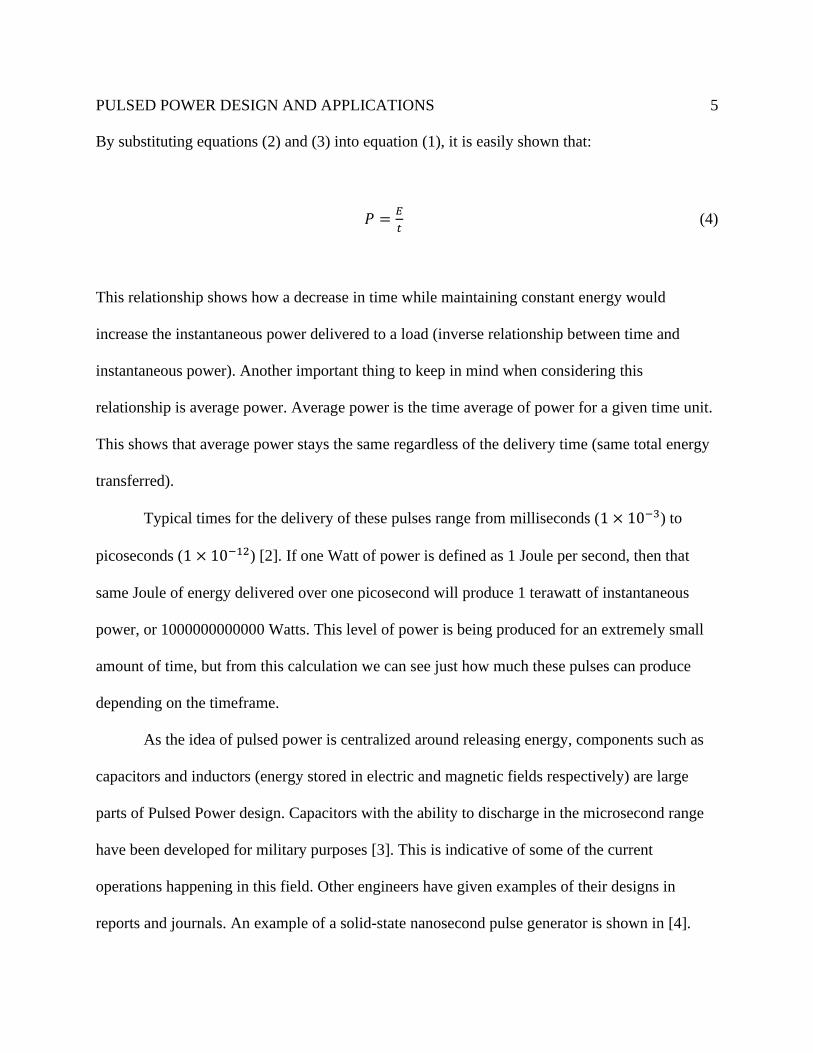
By substituting equations (2) and (3) into equation (1), it is easily shown that:
𝑃 =𝐸
𝑡 (4)
This relationship shows how a decrease in time while maintaining constant energy would
increase the instantaneous power delivered to a load (inverse relationship between time and
instantaneous power). Another important thing to keep in mind when considering this
relationship is average power. Average power is the time average of power for a given time unit.
This shows that average power stays the same regardless of the delivery time (same total energy
transferred).
Typical times for the delivery of these pulses range from milliseconds (1 × 10⁻³) to
picoseconds (1 × 10⁻¹²) [2]. If one Watt of power is defined as 1 Joule per second, then that
same Joule of energy delivered over one picosecond will produce 1 terawatt of instantaneous
power, or 1000000000000 Watts. This level of power is being produced for an extremely small
amount of time, but from this calculation we can see just how much these pulses can produce
depending on the timeframe.
As the idea of pulsed power is centralized around releasing energy, components such as
capacitors and inductors (energy stored in electric and magnetic fields respectively) are large
parts of Pulsed Power design. Capacitors with the ability to discharge in the microsecond range
have been developed for military purposes [3]. This is indicative of some of the current
operations happening in this field. Other engineers have given examples of their designs in
reports and journals. An example of a solid-state nanosecond pulse generator is shown in [4].
PULSED POWER DESIGN AND APPLICATIONS
6
Historical Background
This section will cover a historical background of pulsed power, both its origins and
development throughout time. This is important to the study of this topic as it helps identify the
current state of work and what direction the work in this topic will take as research continues
with time.
Beginnings
Sandia National Laboratories is considered by most to be the birthplace of pulsed power
technology. This process, based on work done Marx Generators in the early 20th century, started
in the 1950s with the intent to utilize it in military applications. Marx Generators are power
generation systems developed by Professor Erwin Marx in 1923 (to be discussed in more detail
at a later point).
Due to growing concern of the effect of Soviet atomic weapons and radiation on United
States military equipment, Sandia was tasked with finding ways to test the vulnerability of this
equipment (gamma radiation in particular). High voltage and very short pulses were needed to
effectively test the potential weapon effects, and this is when pulsed power systems started to
become heavily developed at Sandia, with scientists trying to find the most successful ways to
implement these systems [5]
Atomic Weapons Research Establishment
J.C. Martin and other team members at Atomic Weapons Research Establishment (or
AWRE) were among the first to develop systems capable of delivering pulses of megavolt levels
if the time range was kept in the tens of nanoseconds. This was accomplished through use of
electrodes of very small dimensions inside a suitable vacuum. The teams inside the United States
PULSED POWER DESIGN AND APPLICATIONS
7
utilized much of this research to test the effects of X-Ray and gamma radiation on military
equipment [6]. This collaboration was enabled by the Mutual Defense Agreement of 1958, which
set the baseline for cooperation and work between the United States and Britain on the subject
[5].
Bridge into Modern Day
According to [6], the most successful generators constructed in the United States in the
early period were Marx Generators “charging a single liquid-dielectric transmission line system
that was switched by liquid spark gaps.” A group called Physics International Company (PI)
constructed the first of these systems in 1964, effectively scaling the output of pulsed power
systems by a large factor, which led to an increased application range of pulsed power. The term
pulsed power was first introduced by PI employees at this time to describe their work. Once the
production of these systems was found to have such a revolutionary effect, research started to
expand across the world and across many different fields, such as manufacturing, laser-beam
technology, biological effects, and more. This brings us into the present-day era of research on
pulsed power.
State of Work at LUSE Background
Liberty University’s School of Engineering (LUSE) has recognized the benefits and
advantages of researching pulsed power system design and applications in the modern era of
engineering. A brief background is given here of the work conducted at LUSE, while a more in-
depth study of methodology and results is given further on in this thesis.
Research done on pulsed power at LUSE has been conducted under Dr. Carl Pettiford,
Associate Dean of LUSE. Joshua Zaiter (author) has been working under Dr. Pettiford to verify
PULSED POWER DESIGN AND APPLICATIONS
8
and replicate two existing pulsed power systems to act as a foundation for work at Liberty
University on the subject. Liberty University has been given permission by the original
researchers to conduct this research.
The verification process involves simulation and testing of the systems provided, as well
as their individual sections and components. The physical aspect of this includes printed circuit
board design, physical construction, and physical verification of the generator. If properly
completed, Liberty University will obtain one or more working pulsed power generators,
available for research on different topics such as cancer treatment.
General System Design
There are a great deal of factors to consider when considering, designing, constructing, an
implementing a pulsed power system or generator. As this subject is extremely expansive and
requires a high level of understanding, this section will seek to give a fundamental basis to the
major components and sections of such a system, as well as provide examples from various
sources on the topic.
Dielectric Material Considerations
When designing a pulsed power system, one of the most important things to consider is
the makeup of the devices that store electric or magnetic fields. Capacitors, which store electric
fields, and inductors, which store magnetic fields, are the primary components regarding this
discussion and will be the indicated components when mentioning these devices.
A dielectric material is an insulating material that is used in the capacitor to increase its
capacitance without causing breakdown. Capacitors often consist of two parallel plates that have
PULSED POWER DESIGN AND APPLICATIONS
9
a voltage applied across them. When the voltage is applied across the plates, the capacitor will
accumulate charge (Q). The capacitance of a parallel plate capacitor is given by:
𝐶 = 𝜖0𝐴
𝑑 (5)
𝜖0 is the dielectric permittivity of a vacuum, 𝐴 is the surface area, and 𝑑 is the distance between
the plates [7]. When a dielectric material is added between the plates, the equation for
capacitance is multiplied by the dielectric constant of the material, k. The larger k is, the more
capacitance. These dielectrics are easily polarized and are poor conductors of current.
These dielectric components can exist in a gaseous, liquid, or solid form. They exist not
only in capacitors, but in transmission lines and transformers as well [8]. Along with the
dielectric constant, discussed above, the electric breakdown strength of a material is one of the
deciding properties of such a dielectric. According to [8], the “electric strength of an insulant can
be defined qualitatively as the maximum field stress that the material can withstand for a given
time.” To further understand the idea of electric breakdown, we reference the previous claim that
dielectrics are poor conductors of current. When a given material is subject to a sufficiently high
voltage, it will lose that trait and start conducting current. In the field of pulsed power, where the
objective is to produce large amounts of power, often through very high voltage values, the
ability of a dielectric to maintain its properties is a vital trait to consider.
The breakdown strength of a ceramic capacitor for example was found by [9] to be
heavily influenced by 𝜖𝑟, or relative permittivity. To test the breakdown strength of certain
capacitor samples under DC charging and pulse charging, [9] utilized a high voltage test scheme
PULSED POWER DESIGN AND APPLICATIONS
10
as well as a circuit scheme shown in [9]. Results from this study showed that breakdown strength
of the dielectrics used decreased with increasing thickness of dimensions. When the dielectric
constant was the independent variable of testing, results showed a nonlinear decrease of
breakdown strength with an increase in dielectric constant (under DC charging). This study gives
useful parameters for the proper implementation of a dielectric into pulsed power system
components.
One more important note in the study of dielectric choice is made by [8]. Solids, liquids,
and gaseous materials have different uses and advantages in different systems. For example, a
gas or liquid can self-repair following a high voltage induced breakdown, while a solid dielectric
material is unable to self-repair, i.e., it is permanently destroyed. However, if a mechanical force
is in play and the system must withstand this force, a solid dielectric is necessary. Liquid
dielectrics are preferrable in the case of large amounts of heat loss needing to be eliminated.
Energy Storage
Continuing our discussion of pulsed power system design is the study of energy storage
devices. This is considered the first main section in a pulsed power system, with the energy
storage device used determining system parameters such as discharge capabilities, power,
electric/magnetic field strengths, and system resilience. Dielectrics, discussed previously, are a
part of the discussion of energy storage units, but this section will aim to look at the
incorporation of different techniques and methods used in pulsed power generators, not
necessarily the component breakdowns themselves.
[8] gives a list of requirements that an energy storage device should meet for pulsed
power applications: “1) High energy density; 2) High breakdown strength; 3) High discharge
PULSED POWER DESIGN AND APPLICATIONS
11
current capability; 4) Long storage time; 5) High charging and discharging efficiency; 6) Large
power multiplication; 7) Repetition rate capability/long lifetime; 8) Low Specific Cost.”
The author of this list does note that certain tradeoffs are required as some requirements conflict
with others.
Capacitors for Pulse Applications
High voltage capacitors, to this day, are one of the most used energy storage devices in
pulsed power applications. [8] claims this is because “reliable, repetitive, fast closing switches
are easier to build than the opening switches necessary to realize generators based on inductive
storage.” This meets the repetition requirement outlined above. The energy hold time of these
capacitors is also greatly increased compared to the hold times of inductive devices (inductors,
different coil methods, and devices that store energy in magnetic fields) [8]. This meets another
requirement for a storage device.
In addition to the breakdown strength of the dielectric, discussed previously, the
geometry, surface area, and material used for the capacitor terminals all play a part in the high
voltage strength of the capacitor. Other testing and environmental conditions such as
temperature, pressure, humidity, and voltage reversal can affect the threshold for capacitor
breakdown. [8] describes the effect of voltage reversal on capacitor breakdown models in this
way: “If charge has been injected from the metallic-cathode side into the dielectric, the space
charge field associated with it can add to the external field during voltage reversal...” This
additional field placed upon the capacitor and dielectric causes the breakdown stress to be
surpassed and potentially damage the component. Although capacitors are popular due to the
PULSED POWER DESIGN AND APPLICATIONS
12
ease-of-use factor, it is important to keep in mind the factors that affect the lifespan of these
energy storage devices as to not blindly utilize them. This is a tradeoff in the system design.
Marx Generators
Marx Generators, named after their inventor, Erwin Marx (patented in 1923), are very
popular selections for energy storage devices in systems producing pulses with significantly
larger amplitudes than those used on capacitor-only based systems, typically over 100 kV [8].
The transformers needed for high-power charging units become exceedingly large once the
amplitudes reach 100 kV, so another method is required.
The principal idea of a Marx Generator is the storage of electrical energy in banks of
capacitors, similar to how a battery operates [5]. These capacitors are connected and parallel and
receive charge in parallel and are then discharged in series. This connection provides the Marx
Generator with the ability to amplify a low-power signal to a sufficiently large high voltage as
needed by the application. The output voltage of a Marx Generator is found by multiplying the
input voltage, or charging voltage, by the number of stages in the generator circuit [10].
Conceptually, this is understood by analyzing the behavior of capacitors in parallel (connected to
the same electrical node). When supplied by a voltage source, the capacitors accumulate charge
at the same rate until they are fully charged and do not allow current to pass through. Once the
capacitors are triggered by a high-speed switching action, the energy stored is discharged at the
same time, resulting in a voltage directly proportional to the number of stages in the generator.
As implied by Ohm’s Law, as impedance decreases, the available power increases for a
constant voltage supply. This means that for each stage of a Marx Generator, the increased
impedance makes increasing the voltage to extremely high levels (terawatt and higher) very
PULSED POWER DESIGN AND APPLICATIONS
13
difficult. Although voltage is being multiplied across the stages, more and more power is being
lost due to the increased impedance per stage. To solve this problem and access power needed
for certain applications, Marx Generators in ultra-high-power generators must charge an
intermediate capacitor used for storage [8]. By designing a system with an equivalent
intermediate capacitance to the capacitance of the Marx Generator, total energy transfer is
attainable. Water is often used as this intermediate capacitance. Given that water’s breakdown is
related to pulse duration, the transfer must occur very quickly to ensure that the system does not
fail in its goal.
Other determining factors in Marx Generator design, such as stray capacitance, LC
generators, variation in time constant of the load based on switching action, and synchronization
of multiple Marx Generators are outside the scope of this discussion. For further information on
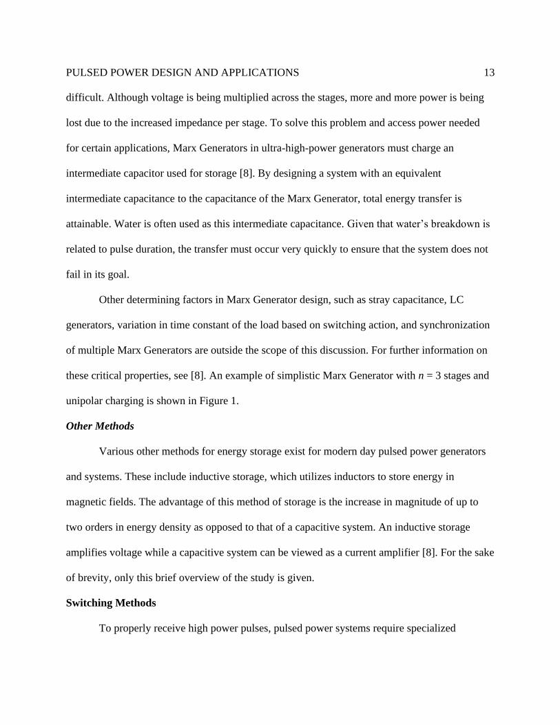
these critical properties, see [8]. An example of simplistic Marx Generator with n = 3 stages and
unipolar charging is shown in Figure 1.
Other Methods
Various other methods for energy storage exist for modern day pulsed power generators
and systems. These include inductive storage, which utilizes inductors to store energy in
magnetic fields. The advantage of this method of storage is the increase in magnitude of up to
two orders in energy density as opposed to that of a capacitive system. An inductive storage
amplifies voltage while a capacitive system can be viewed as a current amplifier [8]. For the sake
of brevity, only this brief overview of the study is given.
Switching Methods
To properly receive high power pulses, pulsed power systems require specialized
PULSED POWER DESIGN AND APPLICATIONS
14
Fig. 1: Example of simplistic Marx Generator with n = 3 stages and unipolar charging (drawn by author). Switches in schematic represent triggers of Marx Generator. Based on [Fig. 3.9, 8].
switching methods that properly trigger discharge or stored energy. These are the next key
element of a general system and lie in between the energy storage devices discussed above and
the target load that receives the energy. Elements such as rise time, shape of pulse, and
magnitude all depend on the implemented switching method. There are four primary stages that
occur within the operation of any switching system, laid out by [8]. The first is the trigger phase,
where the trigger discharge is accumulated. The second is the transition phase, where the
transition between high-to-low switch impedance occurs. The stationary phase occurs when the
switch has constant conductivity, and the last phase is the recovery phase where the prior electric
strength is restored [8]. The major types of switching used in pulsed power systems are discussed
now.
Closing Switches
The use of closing switches is needed for systems with capacitive energy storage devices.
There are various types of closing switches used in modern systems. Among these are gas
switches and semiconductor switches. Gas switches have high ease-of-use and have very precise
trigger values. This is useful for obtaining the quick switching action needed. Gas switches are
PULSED POWER DESIGN AND APPLICATIONS
15
often utilized in systems of high power for their ability to handle large currents and charges.
Types of gas switches include thyratrons, pseudospark switches, ignitrons, and many others.
These lend themselves to different applications and uses [8].
Semiconductor closing switches carry inherent disadvantages not found in gas switches.
The enlargement of the area of the channel that has current flow is the primary way to increase
switching power due to “the relatively low mobility and density of charge carriers in the
plasma...” [8]. Typical semiconductor switches include thyristors and insulated-gate bipolar
transistors (IGBTs).
Opening Switches
In pulsed power systems that utilize inductive storage, opening switches are needed. As
the name implies, opening switches see a sudden rise in impedance when triggered. This means
that current is unable to flow and pass through the switch. There are many requirements for a
usable opening switch, including long current conduction time, large current with small losses,
high impedance when open, and short recovery time, allowing the switch to have high
repeatability. Opening switches are designed using either resistive, capacitive, or inductive
elements. A common example of a resistive fuse is a fuse, such as a melting fuse, that opens
when a certain heat or current condition is met. Inductive opening is realized when the value of
inductance increases with time, while a capacitive opening occurs when capacitance decreases
with time. Typical types of opening switches include mechanical interrupters, plasma opening
switches, and plasma flow switches [8].
PULSED POWER DESIGN AND APPLICATIONS
16
Applications of Pulsed Power
Pulsed power has been developed for a wide array of applications since its inception in
the early 20th century. The following discussion is not an exhaustive list of applications but
rather some of the more well-known use-cases that may also be of interest to Liberty University
from a future-research perspective. Each application’s primary use will be examined as well as
peripheral items such as how it works and the scientific background of the application.
Cancer Treatment Application
The treatment of tumors and cancer is a very relevant topic in the modern-day world,
with the continual search for consistent safe treatments a very pressing burden on scientists of all
kinds. High voltage pulsed power generation has shown the ability to treat cancerous cells and is
a great topic of interest.
What Is It?
High voltage pulses delivered in a very short timeframe, typically in the nanosecond
range in modern research, have shown the ability to induce cell death in tumorous or cancerous
cells. Picosecond range pulses have been experimented with in recent years, however they are
not commonplace. Nanosecond high voltage pulses reach up to 300 kV/cm in many experiments
[2]. The application of the generated electric fields is known as nanosecond pulse electric fields,
or nsPEFs. These nsPEFs, while delivering a large instantaneous power, only deliver a low
amount of actual energy to the load (in this case the tumors). The amount of energy is
determined by the time interval, and with a time interval in the nanosecond range, this total
remains low enough to not play a part in the thermal reactions of the cells. This method induces
PULSED POWER DESIGN AND APPLICATIONS
17
no health setbacks and is attractive as a potential treatment for the future [2]. Success has been
found in treating cancer such as melanoma [2], oral cancer [11], and pancreatic cancer [12].
How Does It Work?
The key to the study of the effects of pulsed power on cancerous cells is a membrane
behavior known as electroporation. Electroporation occurs when an increase in the permeability
in the cell membrane is created because of the applied electric fields. This is possible due to the
short pulse duration. When the cell encounters an external electric field of significance, it
redistributes ions in the membrane to create an opposing electric field to cancel out the field.
With short duration pulses, the field can affect the inside of the cell before the membrane is able
to cancel out the field. When nanosecond pulses are applied, it has been found that intracellular
organelles have been affected and undergo a similar process as the cell membrane. This is known
as supra-electroporation [13]. When supra-electroporation occurs, the intracellular organelles are
damaged, primarily the mitochondria and nucleus of the cell. It is speculated that the damage
inflicted is responsible for the triggering of apoptosis in the cancerous cells [2]. Apoptosis is the
natural programmed cell death resulting from growth and age. This cell death was found to occur
in tests run with high voltage amplitude pulses. In tests run with lower pulse amplitudes, the cells
did not undergo apoptosis immediately but were found to release calcium internally. This release
is thought to be one of the initial triggers of apoptosis [2]. Another possible cause of the damage
seen to the cells is the damage inflicted on DNA in the cell nucleus. This is a very plausible
option but is unconfirmed as of current research [11]. The release of thermal energy has been
shown to be a non-factor in the triggering of apoptosis, as the amount of energy delivered in the
short pulses is not significant enough to change the temperature of the cell [14]. In-depth
PULSED POWER DESIGN AND APPLICATIONS
18
information on the methodology, results, and justifications of a modern-day study into the effects
of electroporation of cancerous cells can be found in [2], [11], and [14].
Electro-Plasticity
What Is It?
The electro-plastic effect, also known as electro-plasticity, is defined as “the reduction in
flow stress of a material undergoing deformation on passing an electrical pulse through it” [15].
This application utilizes high-current pulses (greater than 103 A/cm2) to influence the plasticity
or malleability of different materials, primarily metals [16]. When high-current pulses are
applied to these materials, the plasticity is increased and a decrease in the flow stress is observed.
It has also been found that these pulses give previously brittle metals the ability to undergo
deformation and take other shapes. This has played an instrumental role in industries including
the automotive industry, where shaping and forming metals is a key component to the production
process.
This effect was discovered in the work of O.A. Troitskii in the late 1960s, where
increased elongation of metals was observed, and the effects of lowering flow stress were first
noted [16]. Since then, researchers have delved into effects on different materials and their
applications to industry [17]. Before the innovation of electro-plasticity methods, metals were
deformed through the application of high temperature or constant DC currents. The
disadvantages of the thermal method included a large amount of energy and time allocation to
preheating, heating, and annealing. The high temperatures also lead to thermal stress and
warping in the affected metals [18]. The application of DC current eliminated these negative
PULSED POWER DESIGN AND APPLICATIONS
19
effects but did not retain the maximum elongation of the material. Pulsed power methods retain
the maximum elongation while also avoiding the downsides of the thermal deformation process.
How Does It Work?
Engineers and physicists have not yet come to a complete consensus on the science
behind the electro-plastic effect. However, many theories have been developed. One of these is
the application of Joule-Heating. Joule-Heating occurs when energy passed through the material
is converted to heat, increasing the deformation abilities. This is a tested concept with well-
documented results, although it has been proven to not be the sole cause of the electro-plastic
effect. Testing has occurred in which the pulse applied is short enough to not transfer enough
energy to have a significant thermal effect. The electro-plastic effect was still observed in these
materials, showing the need for another supporting explanation [19].
Another theory behind electro-plasticity is electron wind force. While working on Zn
crystals, Troitskii noted an increase in ductility and a decrease in flow stress when electrons were
directed along the slip plane of a material. After noting the electron behavior, Troitskii concluded
that drift electrons could “exert a force (‘electron wind’) on dislocations and such force should
occur during the passage of an electrical current through a metal being plastically deformed.”
[18]. One other possible explanation for the phenomenon is depinning due to paramagnetic
obstacles. Molotskii and Fleurov believed that the magnetic field generated from the induced
current altered the bonds of the obstacles, leading to the depinning. This theory requires that the
obstacles be paramagnetic [15].
PULSED POWER DESIGN AND APPLICATIONS
20
Current State at Liberty University
One of the focuses of Liberty University’s School of Engineering is to provide research
opportunities in various fields, as well as advance the school’s academic standing. This section
details the research work done by Joshua Zaiter (author) under Dr. Carl Pettiford, Associate
Dean of LUSE in the 2020-2021 academic year.
The goal of the conducted research is to effectively verify, replicate, and test two existing
pulsed power generation systems. These systems are used with permission of the original
research engineers. This section details descriptions of the systems, the current state of work
(including process, expected results, and results), and goals for the future.
System Descriptions
Avalanche Transistor High Voltage Circuit
The first system is a high voltage nanosecond switching circuit utilizing avalanche
transistors. This circuit was developed in [20]. The goal of this system is to generate high voltage
pulses (in the kilovolt range) by switching a high voltage power supply connected to the load.
The circuit was designed to drive a Pockels Cell for a Q-switched Nd:YAG laser within a 0-4.5
kV DC voltage [20].
The pulse circuit consists of three primary sections. These sections are the control unit,
the trigger unit, and the high voltage power supply. The trigger unit, used to chop the high
voltage power supply to ground (0 V), consists of 16 avalanche transistors connected in series.
The avalanche transistor selected by [20] is the ZTX415. Avalanche mode transistors are capable
of extremely fast switching speeds, ideal for use in a pulsed power system where a short falling
time is required. They are defined by [21] as transistors with “a negative resistance region in
PULSED POWER DESIGN AND APPLICATIONS
21
their V-I breakdown curve (usually called secondary breakdown).” This allows controlled
switching of large currents when utilizing proper supporting circuitry (60 A with sub-20 ns pulse
width) and has a maximum collector-emitter voltage of 260 V. A thorough discussion of
ZTX415 characteristics and behaviors can be found in [21].
The control unit is the section of the system used to initiate the trigger unit. A
PIC16F84A microcontroller with a single-push button was utilized by [20] to provide a single 10
μs pulse to a BC547 transistor, which then connects to the trigger unit. This pulse is used to
trigger Q1 (first avalanche transistor). The overvoltage in Q1 causes the avalanche overvoltage
throughout the 16 transistors. [20] employed the use of a single push button to provide the pulse
from the PIC16F84A.
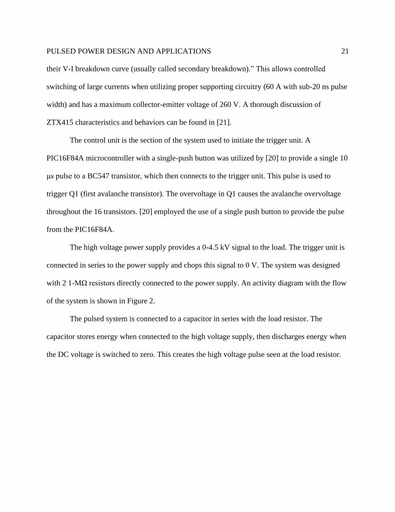
The high voltage power supply provides a 0-4.5 kV signal to the load. The trigger unit is
connected in series to the power supply and chops this signal to 0 V. The system was designed
with 2 1-MΩ resistors directly connected to the power supply. An activity diagram with the flow
of the system is shown in Figure 2.
The pulsed system is connected to a capacitor in series with the load resistor. The
capacitor stores energy when connected to the high voltage supply, then discharges energy when
the DC voltage is switched to zero. This creates the high voltage pulse seen at the load resistor.
PULSED POWER DESIGN AND APPLICATIONS
22
Fig. 2: Activity Diagram of Avalanche Transistor system (drawn by author). Based on [Fig. 2, 20].
Programmable Electroporation System
The second system of interest is a programmable electroporation for biological
applications designed in [22]. Electroporation utilizes the application of electric fields to a cell
membrane to infiltrate the cell and deliver foreign materials to the interior. The goal of this
system is to be able to vary pulse duration, frequency, and total pulse number. The generator
uses power MOSFETs to switch high voltages and can generate electric fields up to 1000 V/cm
with pulse lengths between 10 μs and 20 msec [22].
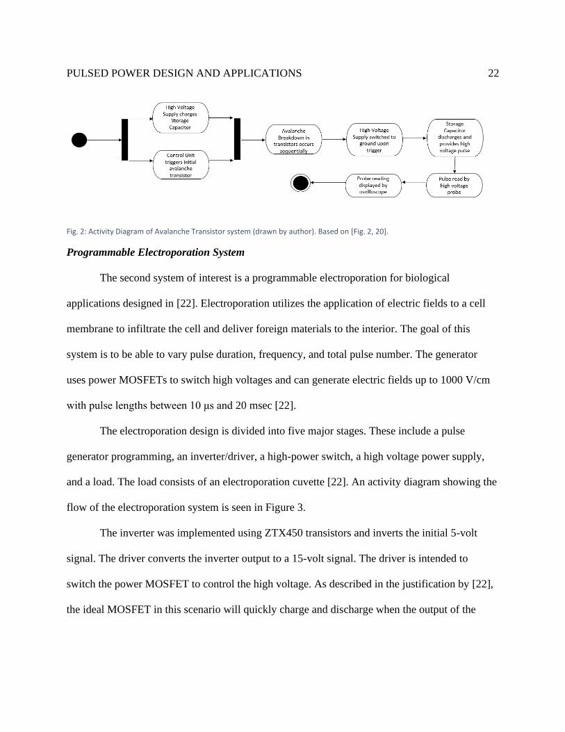
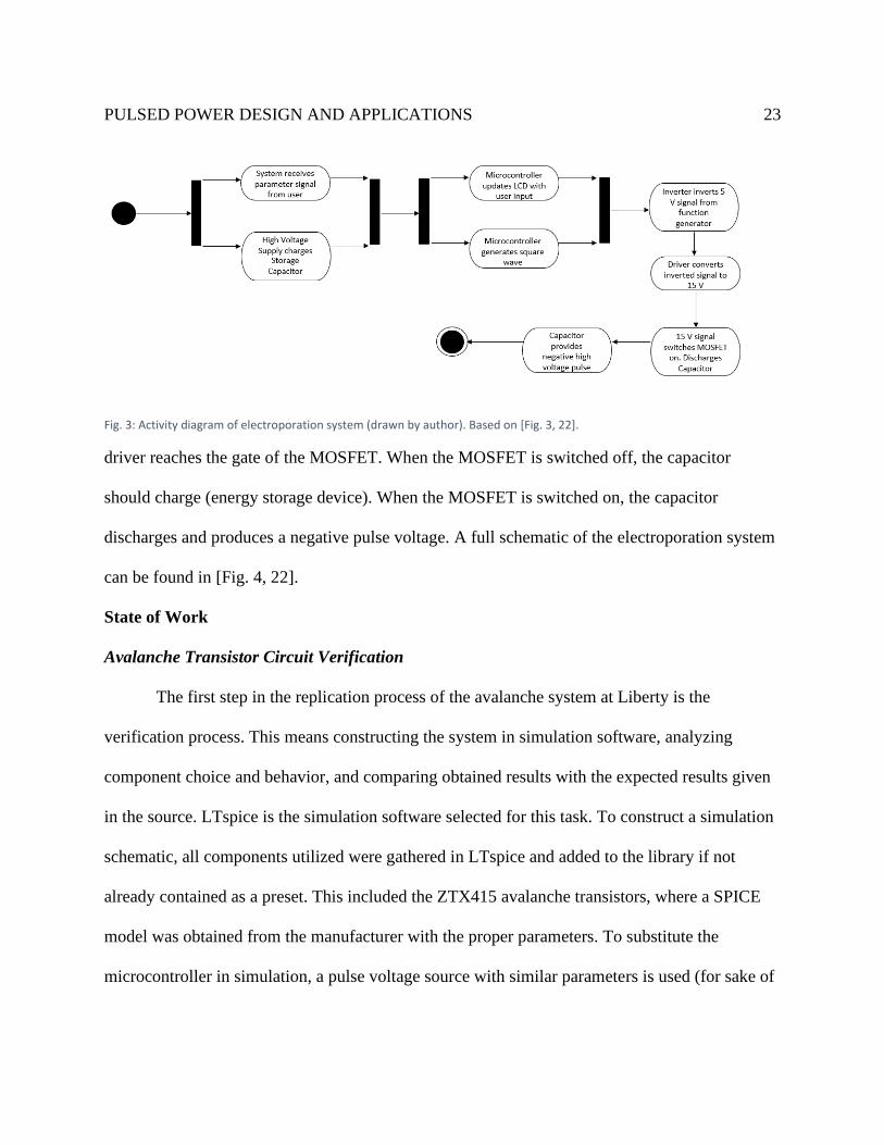
The electroporation design is divided into five major stages. These include a pulse
generator programming, an inverter/driver, a high-power switch, a high voltage power supply,
and a load. The load consists of an electroporation cuvette [22]. An activity diagram showing the
flow of the electroporation system is seen in Figure 3.
The inverter was implemented using ZTX450 transistors and inverts the initial 5-volt
signal. The driver converts the inverter output to a 15-volt signal. The driver is intended to
switch the power MOSFET to control the high voltage. As described in the justification by [22],
the ideal MOSFET in this scenario will quickly charge and discharge when the output of the
PULSED POWER DESIGN AND APPLICATIONS
23
Fig. 3: Activity diagram of electroporation system (drawn by author). Based on [Fig. 3, 22].
driver reaches the gate of the MOSFET. When the MOSFET is switched off, the capacitor
should charge (energy storage device). When the MOSFET is switched on, the capacitor
discharges and produces a negative pulse voltage. A full schematic of the electroporation system
can be found in [Fig. 4, 22].
State of Work
Avalanche Transistor Circuit Verification
The first step in the replication process of the avalanche system at Liberty is the
verification process. This means constructing the system in simulation software, analyzing
component choice and behavior, and comparing obtained results with the expected results given
in the source. LTspice is the simulation software selected for this task. To construct a simulation
schematic, all components utilized were gathered in LTspice and added to the library if not
already contained as a preset. This included the ZTX415 avalanche transistors, where a SPICE
model was obtained from the manufacturer with the proper parameters. To substitute the
microcontroller in simulation, a pulse voltage source with similar parameters is used (for sake of
PULSED POWER DESIGN AND APPLICATIONS
24
simplicity and ease-of-use). This pulse source provides a 10 μs duration pulse to trigger the
initial avalanche transistor (control unit).
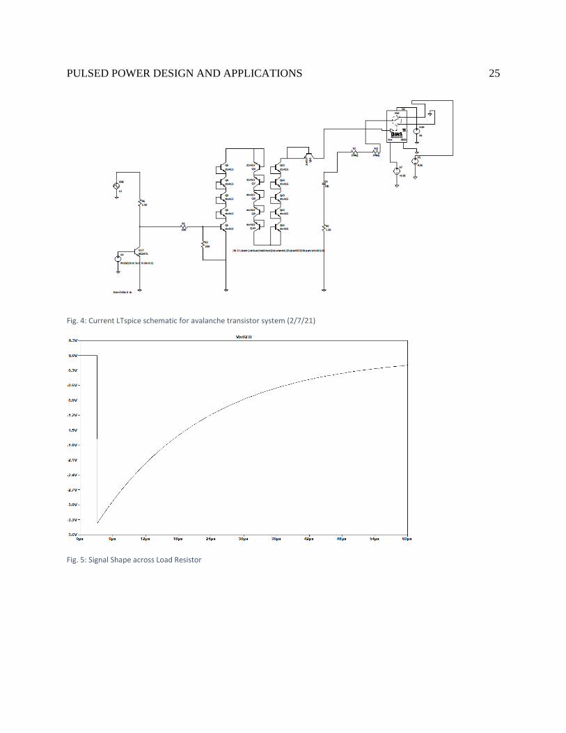
The full LTspice schematic as it exists currently is shown in Figure 4. The control unit is
on the left-most side of the schematic comprised of the pulse voltage source connected to a
BC547C transistor. The trigger unit is in the middle of the figure, consisting of the 16 avalanche
transistors. The high voltage power supply is on the right-most side, connected to a switch
triggered by the trigger unit to chop the voltage down to zero. This is not the completed
schematic for verification as modifications are still being made in an effort to consistently
replicate expected results.
The expected result across the load of this system is a high voltage pulse (up to 4.5
kilovolts) with an average of switching falling time of 2.89 ns. The circuit should produce
negative voltage values that are in a linear relationship with the applied voltage from the power
supply. Expected high voltage switching signal results are found in [Fig. 4, 20] and typical
nanosecond pulse results are found in [Fig. 5, 20].
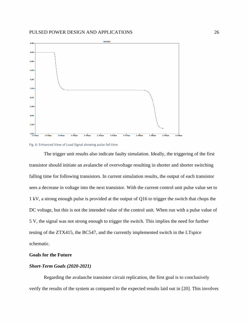
As of February 7, 2021, the obtained results of simulation are not entirely consistent with
expected results. A signal shape has been obtained across the load resistor (Figure 5). This signal
has a similar shape to the one found in the expected high voltage switching signal [Fig. 4, 20].
However, there is indication for continued analysis and modification. The voltage values
obtained via simulation max at magnitudes less than 5 volts. The expected magnitude should be
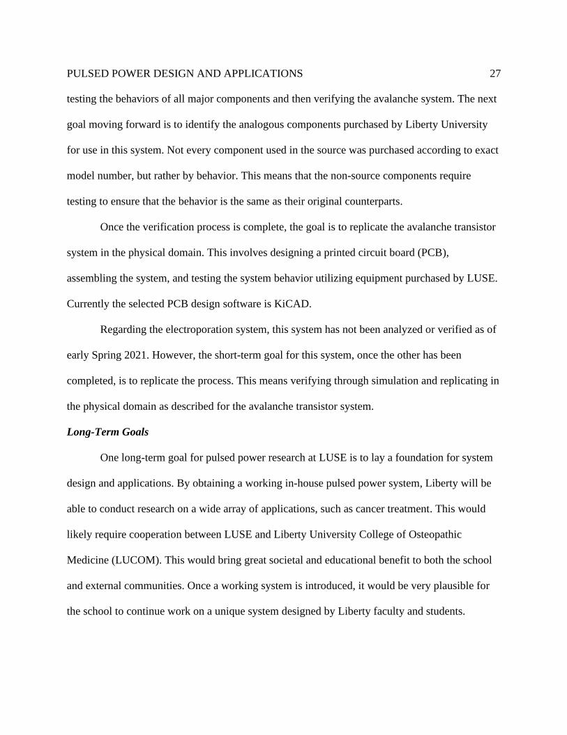
corresponding to the high voltage supply, reaching the kilovolt range. The falling time of this
pulse, shown in Figure 6, is within the nanosecond range, but is much larger than the expected
value of ~3 ns, reaching its max value in 50 ns.
PULSED POWER DESIGN AND APPLICATIONS
25
Fig. 4: Current LTspice schematic for avalanche transistor system (2/7/21)
Fig. 5: Signal Shape across Load Resistor
PULSED POWER DESIGN AND APPLICATIONS
26
Fig. 6: Enhanced View of Load Signal showing pulse fall time
The trigger unit results also indicate faulty simulation. Ideally, the triggering of the first
transistor should initiate an avalanche of overvoltage resulting in shorter and shorter switching
falling time for following transistors. In current simulation results, the output of each transistor
sees a decrease in voltage into the next transistor. With the current control unit pulse value set to
1 kV, a strong enough pulse is provided at the output of Q16 to trigger the switch that chops the
DC voltage, but this is not the intended value of the control unit. When run with a pulse value of
5 V, the signal was not strong enough to trigger the switch. This implies the need for further
testing of the ZTX415, the BC547, and the currently implemented switch in the LTspice
schematic.
Goals for the Future
Short-Term Goals (2020-2021)
Regarding the avalanche transistor circuit replication, the first goal is to conclusively
verify the results of the system as compared to the expected results laid out in [20]. This involves
PULSED POWER DESIGN AND APPLICATIONS
27
testing the behaviors of all major components and then verifying the avalanche system. The next
goal moving forward is to identify the analogous components purchased by Liberty University
for use in this system. Not every component used in the source was purchased according to exact
model number, but rather by behavior. This means that the non-source components require
testing to ensure that the behavior is the same as their original counterparts.
Once the verification process is complete, the goal is to replicate the avalanche transistor
system in the physical domain. This involves designing a printed circuit board (PCB),
assembling the system, and testing the system behavior utilizing equipment purchased by LUSE.
Currently the selected PCB design software is KiCAD.
Regarding the electroporation system, this system has not been analyzed or verified as of
early Spring 2021. However, the short-term goal for this system, once the other has been
completed, is to replicate the process. This means verifying through simulation and replicating in
the physical domain as described for the avalanche transistor system.
Long-Term Goals
One long-term goal for pulsed power research at LUSE is to lay a foundation for system
design and applications. By obtaining a working in-house pulsed power system, Liberty will be
able to conduct research on a wide array of applications, such as cancer treatment. This would
likely require cooperation between LUSE and Liberty University College of Osteopathic
Medicine (LUCOM). This would bring great societal and educational benefit to both the school
and external communities. Once a working system is introduced, it would be very plausible for
the school to continue work on a unique system designed by Liberty faculty and students.
PULSED POWER DESIGN AND APPLICATIONS
28
Another long-term goal for this work is to involve students in the research process at
LUSE. Work in a high-level field such as pulsed power holds great academic value for students
and provides an avenue to pursue graduate research and education. Work of this level at the
undergraduate level also provides a useful experience for students when pursuing opportunities
in the engineering field.
Conclusions
The study of pulsed power system design and its applications is an extremely useful
research topic for Liberty University. The design of a general system has been well-documented
since its inception in the 20th century and continues to be improved upon by engineers across the
world. By analyzing the major sections of a general system, a better grasp on actual
implementation is gained.
The process of replicating existing pulsed power system gives Liberty University the
ability to conduct research and testing on various applications. The biological applications of
such a system are of particular interest, as physical health is a common goal shared by society
across the globe. The ability to aid in bacterial decontamination, cancer treatment, gene therapy,
and other issues is a great humanitarian need and aids in Liberty University’s mission to show
the love of Christ while training Champions for Christ. We hope to complete the verification of
these systems and implementation into the physical domain soon, providing the baseline for
work on pulsed power at LUSE.
PULSED POWER DESIGN AND APPLICATIONS
29
References
[1] J. Kolb, "pulsedpower," September 2011. [Online]. Available:
http://www.pulsedpower.eu/index.html. [Accessed 4 February 2021].
[2] K. H. Schoenbach, B. Hargrave, R. P. Joshi, J. F. Kolb, R. Nuccitelli, C. Osgood, A.
Pakhomov, M. Stacey, Swanson, R. James, J. A. White, S. Xiao and J. Zhang,
"Bioelectric Effects of Intense Nanosecond Pulses," IEEE Transactions on Dielectrics
and Electrical Insulation, pp. 1088-1109, 2007.
[3] F. MacDougall, R. Jow, J. Ennis, S. P. S. Yen, X. H. Chip Yang and J. Ho, "Pulse Power
Capacitors," in 2008 IEEE International Power Modulator Conference, Las Vegas, 2008.
[4] F. Wang, T. Tang, C. Cathey, A. Kuthi and M. Gundersen, "Solid-State High Voltage
Nanosecond Pulse Generator," 2005.
[5] A. V. Arsdall, "Pulsed Power at Sandia National Laboratories: The First Forty Years,"
2008. [Online]. Available: https://www.sandia.gov/Pulsed-
Power/newsreleases/reports/Pulsed_PWR_1st_40yrs.pdf. [Accessed 5 February 2021]
[6] I. Smith, "The Early History of Western Pulsed Power," IEEE Transactions On Plasma
Science, vol. 34, no. 5, pp. 1585-1609, 2006.
[7] Lumen, "Capacitors and Dielectrics," [Online]. Available:
https://courses.lumenlearning.com/physics/chapter/19-5-capacitors-and-dielectrics/.
[Accessed 9 January 2021].
[8] H. Bluhm, Pulsed Power Systems, Berlin: Springer, 2006.
PULSED POWER DESIGN AND APPLICATIONS
30
[9] P. Jiang, J. Yuan, H. Liu, L. Wang, H. Li, W. Xie and Q. Zhang, "Breakdown
Characteristics of Ferroelectric Glass-Ceramic Dielectric for Pulsed Power Applications,"
IEEE Transactions On Plasma Science, vol. 45, no. 4, pp. 698-701, 2017.
[10] K. Rainwater, D. Barnett, C. Lynn, J. Dickens, A. Neuber and J. Mankowski, "A 160 J,
100 Hz Rep Rate, Compact Marx generator for Driving and HPM Source," in 2016 IEEE
International Power Modulator and High Voltage Conference, San Francisco, 2016.
[11] J. Guo, F. Dong, L. Ding, K. Wang, J. Zhang and J. Fang, "A novel drug-free strategy of
nano-pulse stimulation sequence (NPSS) in oral cancer therapy: In vitro and in vivo
study," Bioelectrochemistry 123, pp. 26-33, 2018.
[12] Z. Ren, X. Chen, G. Cui, S. Yin, L. Chen, J. Jiang, Z. Hu, H. Xie, S. Zheng and L. Zhou,
"Nanosecond Pulsed Electric Field Inhibits Cancer Growth Followed by Alteration in
Expressions of NF-κB and Wnt/β-Catenin Signaling Molecules," PLOS One, 2013.
[13] S. J. Beebe, N. M. Sain and R. Wei, "Induction of Cell Death Mechanisms and Apoptosis
by Nanosecond Pulsed Electric Fields (nsPEFs)," Cells, pp. 136-162, 2013.
[14] R. Nuccitelli, "Application of Pulsed Electric Fields to Cancer Therapy," Bioelectricity,
vol. I, no. 1, 2019.
[15] A. Lahiri, P. Shanthraj and F. Roters, "Understanding the mechanisms of electroplasticity
from a crystalplasticity perspective," Modelling and Simulation in Materials Science and
Engineering 27, 2019.
[16] H. Conrad, "Electroplasticity in metals and ceramics," Materials Science and
Engineering, pp. 276-287, 2000.
PULSED POWER DESIGN AND APPLICATIONS
31
[17] H.-D. Nguyen-Tran, H.-S. Oh, S.-T. Hong, H. N. Han, J. Cao, S.-H. Ahn and D.-M.
Chun, "A Review of Electrically-Assisted Manufacturing," International Journal of
Precision Engineering and Manufacturing, pp. 365-376, 2015.
[18] L. Guan, G. Tang and P. K. Chu, "Recent advances and challenges in electroplastic
manufacturingprocessing of metals," Journal of Materials Research, pp. 1215-1224,
2010.
[19] D. Andre, T. Burlet, F. Korkemeyer, G. Gerstein, S. Sandloebes-Haut and S. Korte-
Kerzel, "Investigation of the electroplastic effect using nanoindentation," May 2019.
[Online]. Available:
https://www.researchgate.net/publication/333564186_Investigation_of_the_electroplastic
_effect_using_nanoindentation.
[20] A. R. Tamuri, N. Bidin and Y. M. Daud, "Nanoseconds Switching for High Voltage
Circuit Using Avalanche Transistors," Applied Physics Research, pp. 25-29, 2009.
[21] N. Chadderton, "The ZTX415 Avalanche Mode Transistor," January 1996. [Online].
Available: https://www.diodes.com/assets/App-Note-Files/zetex/an8.pdf. [Accessed
November 2020].
[22] S. Rodamporn, S. Beeby, N. Harris, A. Brown and J. Chad, "Design and Construction of
a Programmable Electroporation system for Biological Applications," in ThaiBME, 2007.
[23] F. Gallo, S. Satapathy and K. Ravi-Chandar, "Plastic deformation in electrical conductors
subjected to short-duration current pulses," Mechanics of Materials, vol. 55, pp. 146-162,
2012.
PULSED POWER DESIGN AND APPLICATIONS
32
[24] S. Shkuratov, M. Kristiansen, J. Dickens and J. Hernandez, "The current mode of pulsed
power generation in moving magnet systems," PPPS-2001 Pulsed Power Plasma Science
2001, pp. 967-970, 2001.
[25] Kuomamoto University, "Nanosecond pulsed electric fields activate immune cells.,"
ScienceDaily, 2019.
[26] F. Arntz, J. Casey, M. Kempkes, N. Butler and M. Gaudreau, "Solid-State High Voltage
Pulse Power In The 10-100 Nanosecond Regime," in Proceedings of EPAC, Edinburgh,
Scotland, 2006.
[27] J. Deng, "Overview of Pulsed Power Research at CAEP," IEEE Transactions on Plasma
Science, vol. 43, no. 8, pp. 2760-2765, 2015.
[28] J.-H. Roh, J.-J. Seo, S.-T. Hong, M.-J. Kim, H. N. Han and J. T. Roth, "The mechanical
behavior of 5052-H32 aluminum alloys under a pulsed electric current," International
Journal of Plasticity, vol. 58, pp. 84-99, 2014.
[29] S. Zabihi, F. Zare, G. Ledwich, A. Ghosh and H. Akiyama, "A new generation of high
voltage pulsed power converters," in Proceedings of the 20th Australasian Universities
Power Engineering Conference: Power Quality for the 21st Century, Christchurch, 2010.