jonathan c. cherry, p.e. kennecott - department of natural ... · mining of the ore deposit will be...
TRANSCRIPT

Jonathan C. Cherry, P.E. General Manager Kennecott Eagle Minerals Company 1004 Harbor Hill Drive Suite 103 Marquette, Michigan 49855 Phone: 906-225-5791 Email: [email protected]
KennecottEagle Minerals
Mr. Thomas Wellman, Manager Mineral and Land Management Section Forest, Mineral and Fire Management Department of Natural Resources P.O. Box 30452 Lansing, MI 48909-7952 December 14, 2007
Re: Response to questions and clarifications Dear Mr. Wellman, In response to you letter dated 7 December 2007, I am transmitting the following documents as requested.
1. Specific rational to support the proposed location for the surface facilities and portal entrance.
2. Subsidence Monitoring Plan 3. TDRSA Leak Detection System Plan 4. Mine Groundwater Assessment Plan 5. Impervious Surface Inspection Plan 6. Topsoil Monitoring Plan 7. Portal Abandonment Plan
You also requested the names of the Lessee representative and alternate who are authorized to make decisions regarding maintenance and operation of the premises for the Lessee. Those two individuals are Jon Cherry (General Manger) and Bill Henry (Mine and Construction Manager). Also as requested, the Department should direct all notifications to me as follows:
Mr. Jonathan Cherry, P.E. General Manager Kennecott Eagle Minerals Company 1004 Harbor Hills Drive, Suite #103 Marquette, MI 49855
If you have any questions regarding these plans or the responses provided, please contact me at your earliest convenience at 906-225-5791 or via email at [email protected]. Sincerely,
Jonathan C. Cherry, P.E. General Manager

Mr. Thomas Wellman December 14, 2007 Page 2 of 3 Attachments Cc: Mr. Harold Fitch, DEQ Mr. Joe Maki, DEQ Ms. Lynne Boyd, DNR Mr. William Brondyke, DNR Mr. Milt Gere, DNR Mr. Steve Donohue, Foth Environment and Infrastructure Mr. Gene Smary, Warner Norcross & Judd

Memorandum
2737 S. Ridge Rd., Ste.600 PO Box 12326 Green Bay, WI 54307-2326 (920) 497-2500 Fax: (920) 497-8516 J:\scopes\04w018\5000-Client External Correspondence\memos\m-design basis for surf fac loc.doc 1
December 14, 2007 TO: Jon Cherry, Kennecott Eagle Minerals Company CC: Steve Donohue. Foth Infrastructure & Environment, LLC Dennis Donohue, Warner, Norcross & Judd Master File 04W018-5001 FR: John Starke, Foth Infrastructure & Environment, LLC RE: Location Selection Basis for the Eagle Project Surface Facility This memorandum presents the location selection basis for the Eagle Project surface facilities. Surface ownership of the Eagle Project and surrounding area is shown in Figure 1. There are two parts of surface facilities for the project: the main surface facility comprised of 88 acres of disturbed land; and the backfill facility comprised of 9.8 acres of disturbed land. The backfill facility location is close to the Salmon Trout River and is dictated by the ore body and the underground mine design, therefore no alternative locations are available. Operations at the backfill facility have been kept to a minimum to reduce environmental risk and footprint. The location of the main facility was selected to minimize the environmental footprint of the Eagle Mine and to provide a safe and efficient operational area for mining activities. Criteria used to select the proposed location of the main facility are discussed below.
1. Minimize the environmental footprint of the facility.
KEMC designed the main surface facility in the smallest disturbed footprint that would allow safe and effective mining operations. The facility includes:
Two contact water basins, three non-contact water basins, Temporary development storage area, Sanitary system, Parking areas, Mine office building, Coarse ore storage area, Gatehouse, Powder magazines, Truck wash, Treated water infiltration system, Wastewater treatment plant, Generator Building, Fuel storage area, Other ancillary facilities.

J:\scopes\04w018\5000-Client External Correspondence\memos\m-design basis for surf fac loc.doc 2
These facilities are contained within the smallest area will allow safe and efficient mine operations. Containing the operations within a smaller area would result in inefficient operations and cause potential vehicle hazards or unsafe operating conditions.
2. Reducing impacts to surface water or groundwater resources.
The main surface facility is located east of the local groundwater divide. This location reduces risk to the Salmon Trout River Main Branch from mining activities. The facility has been designed to protect the environment whether it’s located west or east of the groundwater divide. However, locating the facility as proposed east of the groundwater divide, provides an extra measure of protection as the closest down gradient surface water is over a mile to the north.
3. Reducing impact to natural wooded areas. KEMC chose a main facility location and alignment to lessen removal of large trees. The proposed position of the surface facilities is located in previously clear-cut areas. As such, wooded tracks of land surrounding the site will remain and will screen the operations from surrounding properties.
4. Provide a facility location that can be screened by natural site features.
The location of the main surface facility was selected to make use of natural screening from Triple A Road and the surrounding properties. A large portion of the main surface facility will be screened by existing wooded areas and by the rock outcrop. These natural features will not only reduce visual impacts of the site operations, but will also buffer noise from operations. Although KEMC could position the facility on Kennecott land, this would result in less screening between Triple A Road and the main surface facility.
5. Locate mine portal to provide safest possible access point. The mine portal entering the bedrock near the outcrop will provide stable access to the ore body. Positioning the portal at a location more distant from the rock outcrop would require extending the portal through loose, unstable alluvial soils thus would increase the risk to the aquifer and result in a less safe portal. From a safety perspective, KEMC believes the mine portal is best positioned near the outcrop to utilize the structural benefit of the natural rock mass.
6. Need for state land use.
KEMC-owned land was considered for the surface facilities operations. However, for the previously stated reasons, state-owned land better meets the location criteria. These location criteria include:
Lowering risk to groundwater and surface water resources, Minimizing disturbance and cutting of wooded areas, Minimizing noise and visual impact from the main facility, Providing safe access to the ore body using the structurally sound rock near the
outcrop, and Minimizing the environmental footprint and risk of the facility by containing
operations into the most practicable and safe area.

1. Surface Rights Boundary, Ore Body and Orthophotography
supplied by Kennecott via Golder Associates Inc., August, 2005.
2. Horizontal datum based on NAD 83/94.
Horizontal coordinates based on UTM Zone 16.
3. Property Ownership supplied from Kennecott and
Coleman Engineering
4. Site Location - Project Site within Sections 11 &12, T50N, R29W,
Michigamme Township, Marquette County, Michigan.0 300 600
Meters
Main Surface Facility
Longyear
Fraley Bros. & Sons
Longyear
L F Louck andDavid Lake
PlumCreek Longyear
Longyear
Mudjekewis LLC
PlumCreek
PlumCreek
PlumCreek
LongyearRealty
LindaBuck
Yellow DogWatershed Preserve
State ofMichigan
State ofMichigan
State ofMichigan
State ofMichigan
Robert ROberg et al
PlumCreek
MudjekewisLLC
State ofMichigan
State ofMichigan
MudjekewisLLC
PlumCreek
PlumCreek
Davenport Foundation
Longyear
Longyear
Boss
11 12
131415
10
03 02 01
State ofMichigan
PlumCreek
State ofMichigan
State ofMichigan
PlumCreek
State ofMichigan
State ofMichigan
State ofMichigan
State ofMichigan
Longyear
Barton & RoseLuoma
Willard Kari
Donald& BelleJacksonLongyear
Realty
J HeirsLongyear
Turner Properties
PlumCreek
StephenKent
PlumCreek
07
18
06
16
09
04
08
17
05
Backfill Facility
428000
428000
429000
429000
430000
430000
431000
431000
432000
432000
433000
433000
434000
434000
435000
435000
436000
436000
5175000
5175000
5176000
5176000
5177000
5177000
5178000
5178000
5179000
5179000
LEGEND
M:\kmceagle\mxd\Facility_Loc_Memo\surface_rights_11x17.mxd December 13, 2007
³Scale:
Prepared by:
Date:
04W018
DECEMBER, 2007
FIGURE 1
PROJECT SURFACE OWNERSHIP
REVISED DATE BY DESCRIPTION
CHECKED BY:
APPROVED BY:
APPROVED BY:
DATE:
DATE:
DATE: DAT
NOTES
SVD1 DEC. '07
JOS1 DEC. '07
Eagle Ore Body
Kennecott Surface Ownership
Location of Surface Facilities
Section Lines
State Leased Area
R29W R28W
T51N
T50N
Foth Infrastructure & Environment, LLC
Project No:
Plan
Eagle Project Subsidence Monitoring Plan Project No.: 04W018
Kennecott Eagle Minerals Company Marquette, Michigan
December 2007

Eagle Project
Subsidence Monitoring Plan
Project ID: 04W018
Prepared for Kennecott Eagle Minerals Company
ISO 14001:2004 Registered System
Prepared by Foth Infrastructure & Environment, LLC
December 2007
Foth Infrastructure & Environment, LLC 2007 2737 South Ridge Road, Suite 600 • P.O. Box 12326 • Green Bay, WI 54307-2326 • (920) 497-2500 • Fax: (920) 497-8516

J:\scopes\04w018\10000\FVD reports\Subsidence Mon Plan\r-text.doc ii
Eagle Project Subsidence Monitoring Plan
Contents
Page 1 Introduction .............................................................................................................................1
1.1 Background....................................................................................................................1 1.2 Purpose...........................................................................................................................1
2 Subsidence Monitoring............................................................................................................2 2.1 Baseline Survey .............................................................................................................2 2.2 Monitoring During Mining Operations..........................................................................2 2.3 Closure and Post Closure Monitoring............................................................................2
3 Subsidence Response Plan ......................................................................................................3 3.1 Measurable Subsidence..................................................................................................3 3.2 Subsidence Response - Assessment Monitoring............................................................3
4 Corrective Action ....................................................................................................................4
Tables Table 3-1 Subsidence Response Parameters ............................................................................3
Figure Figure 1 Subsidence Monitoring Plan
Appendix Appendix A Subsidence Monitoring Log

LJS\J:\scopes\04w018\10000\FVD reports\Subsidence Mon Plan\r-text.doc Foth Infrastructure & Environment • 1
1 Introduction
1.1 Background
Kennecott Eagle Minerals Company (KEMC) is planning to develop an underground nickel and copper mine (Eagle Mine) in Michigamme Township, Marquette County, Michigan. The ore deposit is a high-grade magmatic sulfide deposit containing nickel and copper. Mining of the ore deposit will be conducted underground using blasthole stoping methods. Over the seven year life of the mine, approximately 3,400,000 tonnes of ore will be extracted. The extracted ore will be hauled to the surface, crushed and transported to a mill for processing. 1.2 Purpose
During and after mining operations, KEMC will implement a subsidence monitoring plan as presented herein. The subsidence monitoring plan will measure ground and subsurface displacements at pre-established locations to determine if movements substantiate a detrimental surface subsidence as a result of mining.

LJS\J:\scopes\04w018\10000\FVD reports\Subsidence Mon Plan\r-text.doc Foth Infrastructure & Environment • 2
2 Subsidence Monitoring Surface subsidence monitoring will be conducted at six locations as shown on Figure 1. In addition, subsurface subsidence monitoring will be conducted in one borehole at the location shown on Figure 1. At the surface locations, permanent survey monuments will be installed by a professional land surveyor. The subsurface monitoring will be conducted via strain gauge or similar device installed in the borehole at approximate elevation 1360 feet (414 meters), approximately 20 feet (6 meters) below the bedrock surface. The strain gauge will measure deflection as a result of subsurface rock displacement that could occur due to mining activities. Subsidence monitoring will be recorded on the subsidence monitoring log provided in Appendix A. 2.1 Baseline Survey
One month prior to any underground activities, KEMC will begin ground surface measurements at the monuments and at the borehole, continuing monthly thereafter. The baseline data will be used to monitor subsidence during mining operations. 2.2 Monitoring During Mining Operations
During mining operations, subsidence monitoring will be conducted monthly to assess ground displacement due to mining. The subsidence response plan is detailed in Section 3. The subsidence monitoring data will be maintained on-site and will be available to the Department if requested. 2.3 Closure and Post Closure Monitoring
At the end of mining operations monitoring, subsidence monitoring will be reduced to a semi-annual basis.

LJS\J:\scopes\04w018\10000\FVD reports\Subsidence Mon Plan\r-text.doc Foth Infrastructure & Environment • 3
3 Subsidence Response Plan
3.1 Measurable Subsidence
Measurable subsidence is a surface monument displacement of more than 2-inch monthly cumulative from baseline conditions or greater than ½ inch displacement from the previous measurement or a subsurface gauge displacement of more than 2-inches cumulative from baseline conditions. A summary of parameters appears in Table 3-1.
Table 3-1 Subsidence Response
Location Cumulative Single Occurrence(1)
Surface Monument >2.0” 0.50” Subsurface Gauge >2.0” --
(1) Change from previous monthly measurement Prepared by: JOS1 Checked by: SVD1
3.2 Subsidence Response - Assessment Monitoring
If a measurable subsidence is recorded, KEMC’s response is to implement assessment monitoring. KEMC will notify the department within seven days that a measurable subsidence event has been recorded and that assessment monitoring has begun. Assessment monitoring will include increasing the frequency of monitoring to twice monthly and evaluating impact to the environment. KEMC will conduct assessment monitoring for a period of 90 days and will evaluate the mine progress and the potential for additional surface subsidence. If during this period, measurable subsidence is determined to be a result of mining operations, KEMC will notify the Department and implement corrective action as presented in Section 4. KEMC will submit a report to the Department summarizing the assessment monitoring conducted over the previous 90 days and whether corrective action will be required.

LJS\J:\scopes\04w018\10000\FVD reports\Subsidence Mon Plan\r-text.doc Foth Infrastructure & Environment • 4
4 Corrective Action If measurable subsidence is determined and is a result of mining operations, KEMC will implement the following corrective action:
♦ Review and revise the mining plan to stabilize the crown pillar such that surface displacement will be contained below measurable subsidence levels.
♦ Apply stabilization to the crown pillar, including enhanced mechanical reinforcement that
will reduce surface displacement below measurable subsidence. Stabilization could include an enhanced roof bolting pattern and/or other mechanical means to support the mine during operations.
KEMC will implement the corrective action within 30 days after approval of the corrective action plan by the department.

LJS\J:\scopes\04w018\10000\FVD reports\Subsidence Mon Plan\r-text.doc
Figure


LJS\J:\scopes\04w018\10000\FVD reports\Subsidence Mon Plan\r-text.doc
Appendix A

Monitoring PointBaseline Control
Elevation (ft)Date
Monitoring Point Elevation
(ft)Date
Monitoring Point Elevation
(ft)
From Previous Monitoring (ft)
Cumulative Difference (ft)
Current Monitoring Previous Monitoring Difference
Subsidence Monitoring LogKennecott Eagle Minerals Company
Client: Kennecott Eagle Minerals Company Scope ID.: 04W018Project:Prepared by: Date:Checked by: Date:
Eagle Project
J:\scopes\04w018\10000\FVD reports\Subsidence Mon Plan\Subsidence Monitoring Log.xls

Plan
Eagle Project TDRSA Leak Detection System and Response Action Plan Project I.D.: 04W018
Kennecott Eagle Minerals Company Marquette, Michigan
December 2007

J:\scopes\04w018\10000\FVD reports\TDRSA Leak Det Syst Plan\R-text.doc ii
Eagle Project TDRSA Leak Detection System
and Response Action Plan
Contents Page 1. Introduction .............................................................................................................................1
1.1 Purpose...........................................................................................................................1 2. Design and Construction .........................................................................................................2
2.1 Design ............................................................................................................................2 2.2 Construction Quality Assurance ....................................................................................2
3. System Monitoring ..................................................................................................................3 3.1 Inspections and Monitoring of the Leak Detection Sump .............................................3 3.2 Response Action Plan ....................................................................................................3
4. References ...............................................................................................................................5
Tables Table 3-1 Leak Detection System Sump Water Quality Parameters List
Figures Figure 1 TDRSA Liner System and Temporary Cover Figure 2 TDRSA Contact Water Collection Sump and Leak Detection System
Appendix Appendix A TDRSA CQA Plan Appendix B Leak Detection System Inspection Forms

J:\scopes\04w018\10000\FVD reports\TDRSA Leak Det Syst Plan\R-text.doc Foth Infrastructure & Environment • 1
1. Introduction
1.1 Purpose
This TDRSA Leak Detection System and Response Action Plan (“the Plan”) has been prepared for the Kennecott Eagle Minerals Company (KEMC) Eagle Project to describe how the collection of liquid in the Temporary Development Rock Storage Area (TDRSA) Leak Detection System (LDS) will be managed during construction and operations of the TDRSA. The LDS parameters assist in identifying the source of liquid collected and what action, if any, should be taken. During construction and operation of the TDRSA, leak potential will likely originate from specific sources depending on the activities taking place. This plan evaluates the most likely leak sources over the TDRSA life to focus prevention, inspection, and action on the highest risk scenarios. Overall, the most likely opportunity for liner leaks stems from the construction process and during the placement of the first several feet of development rock on the TDRSA base. Recognizing this, a comprehensive construction and installation procedure overseen by assigned Construction Quality Assurance personnel is planned. Rigorous installation inspections are part of the program that minimizes leak risk from quality-control sources. Once the TDRSA liner system is installed and the bottom layer of development rock is placed, leak risk is reduced to a minimum as additional development rock is placed. Water can enter or be present in the TDRSA from several sources: precipitation that leaks through the top cover, precipitation from the active face, infiltration through a liner breach, and water captured during the development rock placement. Water present in the LDS may originate from a liner breach, however, water can also be present from construction activities. This plan has been prepared to allow evaluation of liquid in the LDS and to assess its source. In addition, if the liquid is identified as a liner breach, actions are provided to mitigate the breach(es) and to protect groundwater.

J:\scopes\04w018\10000\FVD reports\TDRSA Leak Det Syst Plan\R-text.doc Foth Infrastructure & Environment • 2
2. Design and Construction
2.1 Design
The TDRSA is an engineered aboveground storage area used to temporarily store rock generated during mine development from the decline, drifts, levels, raises, and other underground workings needed to access the ore body. The rock, called development rock, will be transported from the development face by truck and placed on the lined TDRSA. The quantity of development rock that will be stored in the TDRSA is 247,900 yd3. Once ore mining begins, all development rock stored in the TDRSA will be returned to backfill the mined areas. The TDRSA will have a perimeter berm/access road, perimeter drainage ditch, contact water collection system sump and leak detection sump on the south end. A double liner system will be installed as shown in Figure 1. The TDRSA will first be filled over the entire floor area with a layer of development rock to protect the liner system. The sump and LDS are shown in Figure 2. The LDS will consist of a 40 mil textured HDPE secondary liner and geocomposite drainage layer underlying the primary liner system. The leak detection liner and geocomposite drainage layer will allow collection and monitoring of liquid that may flow into the system as a result of construction water, a breach in the primary liner system, and/or surface or ground water infiltration. The LDS will be installed across the entire subbase and will be connected with the LDS sump. 2.2 Construction Quality Assurance
During construction of the TDRSA liner system, construction quality assurance (CQA) personnel will be on-site to observe that construction procedures and methods are performed in accordance with project and regulatory requirements. A TDRSA CQA Plan appears in Appendix A detailing the inspection and quality controls on liner installation. CQA personnel will follow specific observation protocol to document construction of the TDRSA liner system components including the subgrade, GCL, geomembrane liners (primary and LDS), geocomposite, contact water collection system, and drainage layer soil.

J:\scopes\04w018\10000\FVD reports\TDRSA Leak Det Syst Plan\R-text.doc Foth Infrastructure & Environment • 3
3. System Monitoring
3.1 Inspections and Monitoring of the Leak Detection Sump
Once development rock is being actively placed, the LDS sump will be monitored monthly for the presence of liquid. Inspections will be documented using the inspection forms provided in Appendix B. Liquid in the sump will be detected with a pressure transducer located in the LDS sump (Figure 2). If present, liquid in the sump will be pumped out and the volume recorded. If the volume exceeds 25 gallon per acre per day(gad), (USEPA, 1987), or in this case, 150 gallons for the approximate 6 acre TDRSA, the LDS sump will be checked for presence of liquid the following day. If present, the liquid will be pumped out, volume recorded, and analyzed for the parameters listed in Table 3-1:
Table 3-1 Leak Detection System Sump Water Quality Parameters List
Parameter Analytical Method Threshold Limit Units
Sulfate EPA-375.4/9038 500 mg/L pH Field Measurement -- standard pH units
Prepared by: MJP1 Checked by: JOS1
Sulfate levels of 500 milligrams/liter (mg/L) and greater than 25 gad (150 gal) indicates a breach of the TDRSA primary liner and the Response Action Plan will be implemented. Sulfate concentration less than 500 mg/L indicates the water present is from sources such as construction and no action is needed. 3.2 Response Action Plan
A Response Action Plan (RAP) is a site-specific plan that establishes procedures in the event that liquids are measured in the LDS sump exceeding 25 gad and a sulfate concentration of 500 mg/L or more in accordance with Special Permit Condition F.22 of the Nonferrous Metallic Mineral Mining Permit No. MP 01 2007 (MDEQ, 2007). To implement the RAP, KEMC will proceed as follows:
♦ Notify MDEQ and MDNR in writing of the exceedance within 7 days of its discovery.
♦ Continue daily assessment of liquid quantity and sample testing. If the 25 gad rate continues to be exceeded, KEMC will install a permanent pump in the LDS sump for continuous liquid removal to minimize liquid head on the LDS liner.
♦ Within 30 days after notification of the exceedance, KEMC will submit to MDEQ and
MDNR a report discussing the determination of the nature/source of the liquid and actions taken.

J:\scopes\04w018\10000\FVD reports\TDRSA Leak Det Syst Plan\R-text.doc Foth Infrastructure & Environment • 4
The best option to mitigate a leak will depend on a number of factors including the amount and rate of development rock placed, chemistry of the liquid in the LDS sump, and the effectiveness of the secondary liner system to contain the leakage. Therefore, no single action can be pre-selected. Continuing monitoring of the LDS sump will be key in determining RAP success. Potential actions to be evaluated include:
♦ Installation of an additional liner over the existing in-place development rock. This will prevent precipitation from infiltrating in-place development rock, thus eliminating the source of the liquid transmitted through a liner breach. A permanent pump can be installed in the LDS collection sump to collect the remaining liquid infiltrating through the in-place development rock. Installation of the additional liner could be staged such that development rock would be temporarily placed over the existing rock until the first stage of additional liner is completed. This rock could then be relocated to the additional lined area as the second stage of additional liner is completed. During these construction events, the area could be graded to direct runoff into a temporary, lined pond area created within the TDRSA and the runoff pumped to the CWBs.
♦ Interim cover to prevent precipitation from infiltrating in-place development rock. The
cover could be graded to direct runoff into a temporary, lined pond area created within the TDRSA and the runoff pumped to the CWBs.
♦ Establish a low threshold for pump activation in the contact water collection system sump
such that minimal quantity of liquid and head would be maintained.

J:\scopes\04w018\10000\FVD reports\TDRSA Leak Det Syst Plan\R-text.doc Foth Infrastructure & Environment • 5
4. References ASTM D 7007-03 Standard Practices for Electrical Methods for Locating Leaks in
Geomembranes Covered with Water or Earth Materials Michigan Department of Environmental Quality. General Permit Conditions Nonferrous
Metallic Mineral Mining Permit No. MP 01 2007. Anticipated Issuance Date of December 14, 2007.
USEPA. Background Document of Bottom Liner Performance in Double-Lined Landfills and
Surface Impoundments, EPA/530-SW-87-013 (1987).

J:\scopes\04w018\10000\FVD reports\TDRSA Leak Det Syst Plan\R-text.doc
Figures


J:\scopes\04w018\10000\FVD reports\TDRSA Leak Det Syst Plan\R-text.doc
Appendix A
TDRSA CQA Plan

Report
TDRSA CQA Plan Eagle Project Project I.D.: 04W018
Kennecott Eagle Minerals Company Marquette, Michigan
February, 2006 (Revised July 2006)
(Revised December 2007)

Eagle Project
TDRSA CQA Plan
Project ID: 04W018
Prepared for Kennecott Eagle Minerals Company
ISO 14001:2004 Registered System
Prepared by Foth & Van Dyke and Associates, Inc.
February 2006 (Revised July 2006)
(Revised December 2007)
Foth & Van Dyke and Associates, Inc. 2007 2737 S. Ridge Road, P.O. Box 19012, Green Bay, Wisconsin 54307-9012, 920/497-2500, FAX: 920/497-8516

LJS\J:\scopes\04w018\10000\FVD reports\Final MPA\App I\r-TDRSA CQA Plan.doc\10000 ii
Eagle Project TDRSA CQA Plan
Contents
Page 1 Introduction .............................................................................................................................1
1.1 Purpose and Scope .........................................................................................................1 2 Construction Observation - Record Keeping ..........................................................................2
2.1 Construction Observation Report ..................................................................................2 2.2 Daily Summary Report ..................................................................................................2 2.3 Photographs....................................................................................................................2 2.4 Test Data Sheets.............................................................................................................3 2.5 Document Control and Record Storage .........................................................................3
2.5.1 Daily Records.....................................................................................................3 2.5.2 Storage of Records.............................................................................................3
3 Construction Observation - Testing and Verification .............................................................4 3.1 Survey Verification........................................................................................................4
3.1.1 Tolerances ..........................................................................................................4 3.2 Thickness Verification ...................................................................................................5
4 Construction Observation - Soil Components .........................................................................6 4.1 Scope, Sampling Requirements and Acceptance Criteria..............................................6 4.2 Compacted Subgrade .....................................................................................................6
4.2.1 CQA Officer Inspection of Subgrade and Foundation ......................................6 4.3 Granular Drainage Layer ...............................................................................................6
5 Geotextile Cushioning Layer...................................................................................................8 5.1 On-Site Quality Assurance ............................................................................................8
5.1.1 Geotextile Cushioning Layer Rolls and Panels .................................................8 5.1.2 Geotextile Cushioning Layer Panel Placement..................................................8
6 Construction Observation – GCL............................................................................................9 6.1 On-Site Quality Assurance ............................................................................................9
6.1.1 GCL Rolls and Panels........................................................................................9 6.1.2 Panel Placement ...............................................................................................10
6.2 Documentation and Reporting .....................................................................................10 7 Construction Observation - Geomembrane ...........................................................................11
7.1 On-Site Quality Assurance ..........................................................................................11 7.1.1 HDPE Geomembrane.......................................................................................11
7.1.1.1 Geomembrane Rolls and Panels.......................................................11 7.1.1.2 Panel Placement ...............................................................................13 7.1.1.3 Trial Seam Testing ...........................................................................13 7.1.1.4 Seam Testing and Repair..................................................................14 7.1.1.5 Defect Repairs ..................................................................................15 7.1.1.6 Anchorage Testing ...........................................................................16
7.1.2 PVC Geomembrane .........................................................................................16 7.1.2.1 PVC Panels.......................................................................................16 7.1.2.2 Panel Placement ...............................................................................18

Contents (continued) Page
J:\scopes\04w018\10000\FVD reports\Final MPA\App I\r-TDRSA CQA Plan.doc iii
7.1.2.3 Trial Seam Testing (Thermal Welded Seams) .................................19 7.1.2.4 Seam Testing and Repair..................................................................19 7.1.2.5 Defect Repairs ..................................................................................21 7.1.2.6 Anchorage Testing ...........................................................................21
7.2 Documentation and Reporting .....................................................................................21 8 Construction Observation - Miscellaneous Items..................................................................23
8.1 Geocomposite Drainage Layer ....................................................................................23 8.1.1 Geocomposite Rolls and Panels.......................................................................23 8.1.2 Panel Placement ...............................................................................................23
8.2 Contact Water Collection and Extraction System .......................................................24 8.2.1 Installation........................................................................................................24
9 Construction Observation Report ..........................................................................................25 9.1 Documentation.............................................................................................................25
Tables Table 3-1 Summary of Survey Tolerances.............................................................................. 4 Table 3-2 Summary of Minimum Thicknesses ....................................................................... 5 Table 7-1 Material Properties, Textured HDPE Geomembrane ........................................... 12 Table 7-2 Material Properties, 30 mil PVC Geomembrane .................................................. 17

LJS\J:\scopes\04w018\10000\FVD reports\Final MPA\App I\r-TDRSA CQA Plan.doc\10000 Foth & Van Dyke and Assoc., Inc. • 1 Revised December 2007
1 Introduction
1.1 Purpose and Scope
The purpose of the Construction Quality Assurance (CQA) Plan is to provide minimum requirements for construction observation, testing, and documentation activities performed during construction. This plan is followed during construction to monitor and confirm that the construction features are constructed in accordance with the design and regulatory requirements. The plan outlines the various sampling and testing programs to be carried out during the construction.

LJS\J:\scopes\04w018\10000\FVD reports\Final MPA\App I\r-TDRSA CQA Plan.doc\10000 Foth & Van Dyke and Assoc., Inc. • 2 Revised December 2007
2 Construction Observation - Record Keeping
2.1 Construction Observation Report
The CQA monitor(s) are responsible to collect all samples and perform all Quality Control (QC) testing required by the CQA Plan. A daily report will be prepared by each inspector for each day of activity. The report will contain, at a minimum, the following information:
♦ Date ♦ Type of inspection ♦ Summary of weather conditions ♦ Summary of any meetings held and attendees ♦ Equipment and personnel on the project ♦ Summary of construction activities and locations ♦ Description of off-site materials received ♦ Calibration and recalibration of test equipment ♦ Description of procedures used ♦ Test locations, procedures, results and test data sheets ♦ Summary of samples collected ♦ Personnel involved in inspection and sampling activities ♦ Signature of the inspector ♦ Description of delays in construction activities ♦ Detailed description of any problems or non-conforming construction ♦ Progress of work in terms of approximate quantities
2.2 Daily Summary Report
The CQA officer or the CQA monitors, under the direct supervision of the CQA officer, will prepare a daily summary report containing, at a minimum, the following:
♦ Date ♦ Summary of weather conditions ♦ Summary of location where construction is occurring ♦ Contractors, equipment and personnel on the project ♦ Summary of any meetings held and attendees ♦ Description of all materials used and references or results of testing and documentation ♦ Calibration and recalibration of test equipment ♦ Daily inspection reports from each CQA monitor ♦ Description of any construction not meeting the project requirements and how it was
corrected 2.3 Photographs
Photographs shall be obtained for all items of construction. A sufficient number of photographs shall be obtained to document the construction of each construction item (e.g., each manhole, each type of pipeline, each method of anchoring geomembranes, etc.). Each photograph shall be a 35 mm or digital photograph. A photo log containing the following information will be maintained:

LJS\J:\scopes\04w018\10000\FVD reports\Final MPA\App I\r-TDRSA CQA Plan.doc\10000 Foth & Van Dyke and Assoc., Inc. • 3 Revised December 2007
♦ Date, time, location and orientation of photograph ♦ Name and signature of photographer ♦ Location and description of the work
Construction problems and non-conforming work shall be documented with photographs taken before and after the problem or when the non-conforming work has been corrected. 2.4 Test Data Sheets
CQA monitor will record all test data results on the test data sheets. Independent consultants engaged by the CQA shall submit their test results or data on forms acceptable to and approved by the CQA monitor. 2.5 Document Control and Record Storage
2.5.1 Daily Records The daily records maintained during construction activities include, but are not limited to the following daily records:
♦ Daily inspection reports. ♦ Daily summary reports. ♦ Test data sheets from each CQA monitor. ♦ Test data or documentation data sheets from independent consultants (if any). ♦ Field book maintained by each CQA monitor. ♦ Field notes from all record surveys.
2.5.2 Storage of Records All document originals listed in Section 2.5.1 above will be stored in 3-ring binders at the construction site. Copies of all documents will be on file at the CQA officer's office.

LJS\J:\scopes\04w018\10000\FVD reports\Final MPA\App I\r-TDRSA CQA Plan.doc\10000 Foth & Van Dyke and Assoc., Inc. • 4 Revised December 2007
3 Construction Observation - Testing and Verification This section outlines minimum requirements for the testing and verification of the components of construction. 3.1 Survey Verification
At a minimum, the record surveys shall document the following: Composite Liner System
♦ Subbase of liner on 50-ft grid. ♦ Contact water collection system trench elevations every 25 ft (every 50 ft if a total station
or laser is used). ♦ Geomembrane location information for panels, repairs, destructive tests, and anchor
trench. Contact Water Collection and Extraction System
♦ Collection pipe locations and invert elevations every 25 ft (every 50 ft if a total station or laser is used).
♦ Locations and pertinent elevations of manholes, cleanouts, leak detection sump, and collection sump.
3.1.1 Tolerances Tolerances for each survey are listed in Table 3-1. Areas which do not meet the tolerances listed in Table 3-1 will be regraded or removed and replaced until the tolerances are met and resurveyed.
Table 3-1 Summary of Survey Tolerances
Item Frequency Tolerance
1 Composite Liner
a) Subbase grade 50 ft grid - 0.2 ft
2. Contact Water Collection System
a) Collection piping every 25 ft ± 0.05 ft/100 ft (1)
b) Leak detection sump and collection sump
Bottom/top of sump. Grade breaks/corners
- 0.2 ft
(1)Positive drainage to be maintained at each location Prepared by: MJP1 Checked by: JOS1

LJS\J:\scopes\04w018\10000\FVD reports\Final MPA\App I\r-TDRSA CQA Plan.doc\10000 Foth & Van Dyke and Assoc., Inc. • 5 Revised December 2007
3.2 Thickness Verification
The CQA monitor shall verify the thickness of the gravel drainage layer as indicated in Table 3-2. The method of verification may include survey, hand augers, hand shoveling, or other approved method.
Table 3-2 Summary of Minimum Thicknesses
Item Frequency Minimum Thickness Tolerance
1. Gravel Drainage Layer 200 ft grid min. 1.0 ft +0.1 ft Prepared by: MJP1 Checked by: JOS1

LJS\J:\scopes\04w018\10000\FVD reports\Final MPA\App I\r-TDRSA CQA Plan.doc\10000 Foth & Van Dyke and Assoc., Inc. • 6 Revised December 2007
4 Construction Observation - Soil Components
4.1 Scope, Sampling Requirements and Acceptance Criteria
The following elements of the design shall be constructed and sampled according to the CQA program in this section:
♦ Compacted subgrade ♦ Granular drainage layer
4.2 Compacted Subgrade
All fill materials placed for liner support construction (i.e., subgrade, berms, etc.) shall be tested in accordance with the following schedule:
Test Minimum Frequency Acceptable Test Values
Compaction characteristics: modified Proctor (ASTM D 1557) or standard Proctor (ASTM D 698)
Minimum of 1 test, then an additional 1 test/5,000 cy (in-place)/each soil type,
NA
In-Place Density and Percent Compaction:
(ASTM D 2922 or ASTM D 1556)
100-ft grid/1-ft lift 90% of modified Proctor or 95% of standard Proctor maximum dry
density
4.2.1 CQA Officer Inspection of Subgrade and Foundation The CQA officer or CQA monitor(s) shall perform the following functions during subgrade preparation:
♦ Verify that all trees, stumps, roots, boulders and debris are removed. ♦ Verify that placement of frozen soil or soil onto frozen ground does not occur. ♦ Verify that the foundation is constructed and graded to provide a smooth, workable
surface on which to construct the liner.
4.3 Granular Drainage Layer
All granular drainage layer construction for the contact water collection system shall be tested in accordance with the following schedule:
Test Description Test Method Minimum Frequency Specification
a. Grain Size ASTM D 422 1/1,000 cy < 5% passing No 200 sieve, uniformity coefficient of
less than 4 (gravel soils) or less than 6 (sandy soils)
b. Hydraulic Conductivity ASTM D 2434 1/2,500 cy > 1 X 10⁻³ cm/sec Prepared by: MJP1
Checked by: JOS

LJS\J:\scopes\04w018\10000\FVD reports\Final MPA\App I\r-TDRSA CQA Plan.doc\10000 Foth & Van Dyke and Assoc., Inc. • 7 Revised December 2007
All gravel filter and coarse aggregate material for the leak detection sump and collection system shall be tested in accordance with the following schedule:
Test Description Test Method Minimum Frequency
a. Grain Size ASTM D 422 1/1,000 lin ft of trench
1 per sump
b. Hydraulic Conductivity
ASTM D 2434 Minimum of one sample
In addition, the CQA officer shall inspect the granular drainage layer, gravel filter, and coarse aggregate materials for undesirable objects.

LJS\J:\scopes\04w018\10000\FVD reports\Final MPA\App I\r-TDRSA CQA Plan.doc\10000 Foth & Van Dyke and Assoc., Inc. • 8 Revised December, 2007
5 Geotextile Cushioning Layer
5.1 On-Site Quality Assurance
5.1.1 Geotextile Cushioning Layer Rolls and Panels Construction quality assurance monitoring for geotextile cushioning material rolls and panels includes: 1. Monitoring and documenting the unloading of trucks delivering geotextile rolls to the
site. 2. Monitoring and documenting the handling and on-site storage procedures and location of
the geotextile rolls. 3. Review of manufacturer's QA testing for conformance with project specifications. 5.1.2 Geotextile Cushioning Layer Panel Placement Quality assurance monitoring for geotextile panel placement includes: 1. Monitoring and documenting sewing of adjacent geotextile panels for conformance to the
project specifications.

LJS\J:\scopes\04w018\10000\FVD reports\Final MPA\App I\r-TDRSA CQA Plan.doc\10000 Foth & Van Dyke and Assoc., Inc. • 9 Revised December, 2007
6 Construction Observation – GCL
6.1 On-Site Quality Assurance
6.1.1 GCL Rolls and Panels Construction quality assurance monitoring for the rolls and panels include: 1. Monitoring and documenting the unloading of trucks delivering GCL rolls to the site. 2. Monitoring and documenting the handling and on-site storage procedures and location of
GCL rolls. 3. Recording the manufacturing roll and batch number of GCL rolls delivered to the site,
date of fabrication and physical dimensions. 4. Review of manufacturer's QA testing for conformance with specifications, including: a. Name of the manufacturer and fabricator
b. Copies of quality control certificates that are issued by the producer of the GCL materials.
5. Selecting samples from GCL rolls delivered to the site for off-site conformance testing.
Conformance testing will be performed as outlined below. Samples shall be sent to a geosynthetics testing laboratory for the following material properties:
Test Description Test Method Minimum Frequency Specification
Mass of GCL/unit area ASTM D 5993 40,000 sf 0.82 lb/ft2
Tensile strength ASTM D 6768 100, 000 sf 23 lb/in Peel strength ASTM D 6496 100,000 sf 2.1 lb/in
Free swell of bentonite ASTM D 5890 100,000 sf 24 ml/2g Cap Fabric mass/unit
area ASTM D 5261 100,000 sf 5.8 oz/yd2
6. Fixing a code number to samples and recording the manufacturing numbers of the rolls
from which samples are taken. 7. Labeling, packaging and shipping samples to an off-site laboratory for conformance
testing. 8. Interpreting laboratory test results in accordance with the specifications and accepting or
rejecting delivered rolls based on results of off-site testing. 9. Visual review and marking of GCL as it is unrolled and deployed at the job site for
uniformity, damage, and imperfections, including holes, thin spots, tears, punctures, and foreign matter.

LJS\J:\scopes\04w018\10000\FVD reports\Final MPA\App I\r-TDRSA CQA Plan.doc\10000 Foth & Van Dyke and Assoc., Inc. • 10 Revised December 2007
6.1.2 Panel Placement Quality assurance monitoring for panel placement includes: 1. Obtaining a written acceptance of the subgrade by the GCL installer. 2. Evaluating and documenting weather conditions (e.g., temperature, wind) for GCL
placement and informing the construction manager if requirements for weather conditions are not met, so the construction manager can decide to stop GCL placement.
3. Monitoring and documenting GCL placement as well as conditions of panels as placed.
a. Noting panel defects, tears or other deformities. b. Measuring in-place panel dimensions. c. Recording panel numbers.
4. Documenting that the panels have been installed in accordance with the project and
manufacturer’s specifications. 6.2 Documentation and Reporting
Documenting and reporting methods will be implemented to systematically record results of on-site monitoring. Reporting forms will be used for roll and panel placement. A GCL installer's certificate of acceptance of the subgrade will be obtained prior to placement of GCL panels. A photo log will be created containing photos of all phases of the GCL installation. Copies of test results for all off-site laboratory testing will be forwarded to the on-site supervisor and will be made available to the construction manager. The laboratory test result documents will be maintained in a job file and submitted with the final documentation report.

LJS\J:\scopes\04w018\10000\FVD reports\Final MPA\App I\r-TDRSA CQA Plan.doc\10000 Foth & Van Dyke and Assoc., Inc. • 11 Revised December 2007
7 Construction Observation - Geomembrane The following section summarizes the quality assurance plan for testing and monitoring of the geomembrane liner installation. 7.1 On-Site Quality Assurance
7.1.1 HDPE Geomembrane
7.1.1.1 Geomembrane Rolls and Panels Construction quality assurance monitoring for the rolls and panels include: 1. Monitoring and documenting the unloading of trucks delivering geomembrane rolls to the
site. 2. Monitoring and documenting the handling and on-site storage procedures and location of
geomembrane rolls. 3. Recording the manufacturing roll and batch number of geomembrane rolls delivered to
the site, date of fabrication and physical dimensions. 4. Review of manufacturer's QA testing for conformance with specifications, including: a. Name of the manufacturer and fabricator b. Name and type of liner c. Thickness of liner d. Origin and identification of the raw materials
e. Copies of quality control certificates that are issued by the producer of the raw materials.
f. Reports of tests that are conducted to verify the quality of the raw materials, such
as specific gravity, melt flow index, and percent carbon black. 5. Selecting samples from geomembrane rolls delivered to the site for off-site conformance
testing. Conformance testing will be performed as outlined in Table 7-1. Samples shall be sent to a geosynthetics testing laboratory for material properties.
6. Fixing a code number to samples and recording the manufacturing numbers of the rolls
from which samples are taken. 7. Labeling, packaging and shipping samples to an off-site laboratory for conformance
testing.

LJS\J:\scopes\04w018\10000\FVD reports\Final MPA\App I\r-TDRSA CQA Plan.doc\10000 Foth & Van Dyke and Assoc., Inc. • 12 Revised December 2007
8. Interpreting laboratory test results in accordance with the specifications and accepting or rejecting delivered rolls based on results of off-site testing.
9. Visual review and marking of the geomembrane as it is unrolled and deployed at the job
site for uniformity, damage, and imperfections, including holes, cracks, thin spots, tears, punctures, blisters, and foreign matter.
Table 7-1
Material Properties, Textured HDPE Geomembrane
Property Test Method Units Minimum Frequency
40 mil Acceptance
Criteria
60 mil Acceptance
Criteria
A. Sheet Properties 1. Thickness (min. avg.) ASTM
D5199/ ASTM D5994
Mil 5 places per roll 38 57
a. Lowest Ind. for 8 Out of 10 Values
Mil 36 54
b. Lowest Ind. for Any of 10 Values
Mil 34 51
2. Asperity Height (min. avg.) GRI Procedure GM12
Mil 1/100,000 ft2 min. 1 per resin batch
15 15
3. Tensile Properties (each direction)
ASTM D638 Type IV
a. Yield Strength lb/in. 1/100,000 ft2 min. 1 per resin batch
63 min. 126 min.
b. Break Strength lb/in. 1/100,000 ft2 min. 1 per resin batch
45 min. 90 min.
c. Elongation at Yield % 1/100,000 ft2 min. 1 per resin batch.
12 min. 12 min.
d. Elongation at Break % 1/100,000 ft2 min. 1 per resin batch
100 min. 100 min.
B. Resin Properties 1. Melt Flow Index ASTM D1238 g/10
min. 1/100,000 ft2 min. 1 per resin batch
1.0 max. 1.0 max.
2. Resin Density ASTM D1505 g/cm3 1/100,000 ft2 min. 1 per resin batch
0.93 min. 0.93 min.
C. Seam Properties 1. Peel Strength (fusion)
ASTM D6392
lb/in.
1 per 500 lin ft
50 min.
90 min.
2. Peel Strength (extrusion) ASTM D6392 lb/in. 1 per 500 lin ft 44 min. 78 min. 3. Shear Strength ASTM D6392 lb/in. 1 per 500 lin ft 60 min. 120 min.

LJS\J:\scopes\04w018\10000\FVD reports\Final MPA\App I\r-TDRSA CQA Plan.doc\10000 Foth & Van Dyke and Assoc., Inc. • 13 Revised December 2007
Property Test Method Units Minimum Frequency
40 mil Acceptance
Criteria
60 mil Acceptance
Criteria
4. Peel Strength ASTM D6392 % 1 per 500 lin ft < 25% < 25% D. Environmental Properties 1. Stress Cracking ASTM D5397 hrs. 1 per each resin
batch 200 200
Prepared by: MJP1 Checked by: JOS1
7.1.1.2 Panel Placement Quality assurance monitoring for panel placement includes: 1. Obtaining a written acceptance of the subgrade by the geomembrane installer. 2. Evaluating and documenting weather conditions (e.g., temperature, wind) for
geomembrane placement and informing the construction manager when weather conditions do not meet specifications, so the construction manager can decide to stop geomembrane placement.
3. Monitoring and documenting geomembrane placement as well as conditions of panels as
placed.
a. Noting panel defects, tears or other deformities. b. Measuring panel thicknesses at a minimum of five locations along the length of
each roll. c. Measuring in-place panel dimensions. d. Recording panel numbers.
4. Recording the locations of installed panels and checking that the panels have been
installed in accordance with the design plan.
a. Assigning each panel a unique panel number and identifying that panel with the manufacturer's roll number.
b. Recording panel numbers and locations on a panel layout diagram. 7.1.1.3 Trial Seam Testing Items included in quality assurance monitoring of field seams include the following: 1. Monitoring trial fusion welded seams constructed prior to each seaming sequence to
evaluate the seaming crew and equipment.

LJS\J:\scopes\04w018\10000\FVD reports\Final MPA\App I\r-TDRSA CQA Plan.doc\10000 Foth & Van Dyke and Assoc., Inc. • 14 Revised December 2007
a. Record machine temperature, ambient temperature, machine speed, seamer identification, machine number, date and time for all trial seams.
b. Trial seams will be made at the beginning of each seaming period and at least
once every four hours, for each seaming apparatus used that day. Each seamer will make at least one (1) trial seam each day. Two specimens, 1 inch wide, will be cut from each end of the trial seam (i.e., four samples total). These samples are to be field-tested for shear and peel. Two (2) peel tests will be performed on the inside and outside tracks of the weld and two (2) shear tests will be performed. Alternate shear and peel tests so both tests are performed for each end of the trial seam.
2. Evaluating and documenting trial seam test results in accordance with the specifications
and accepting or rejecting seaming crews and/or equipment. 3. Evaluating and documenting the suitability of weather conditions (e.g., temperature,
wind, humidity) for seaming and informing the construction manager when weather conditions do not meet the specifications so the construction manager can decide to stop geomembrane seaming.
4. Observing and documenting seaming procedures and progress. 5. Assigning a seam number to each seam and recording seam construction data, including
seaming crew identification, date and time of seam construction, ambient temperature. a. Record the location of all seams on a seam layout diagram. 6. Confirming that the installer's field tensiometer has current calibration documentation.
At a minimum, the field tensiometer shall have been calibrated within 3 months prior to start of project.
7.1.1.4 Seam Testing and Repair Items included in the quality assurance for monitoring seam testing and repair include the following: 1. Monitoring and documenting non-destructive testing done to evaluate continuity of all
field and factory-fabricated seams.
a. Observe seam pressure tests and vacuum box tests. b. Mark apparent failed seams for repair. c. Document seam repair and retesting. 2. Selecting locations where geomembrane samples will be taken to conduct destructive
testing. a. A minimum of one destructive test sample will be collected for every 500 lineal
feet of field seam.

LJS\J:\scopes\04w018\10000\FVD reports\Final MPA\App I\r-TDRSA CQA Plan.doc\10000 Foth & Van Dyke and Assoc., Inc. • 15 Revised December 2007
b. Locations of destructive test samples will be noted on a repair and sample
location diagram. 3. Monitoring the cutting of samples by the geomembrane installer. 4. Assigning a unique number to each sample and recording sample locations and other
pertinent observations made during sampling. 5. Monitoring the cutting of the sample in three parts: one for the geomembrane installer,
one for archiving, and one for testing by the off-site laboratory. 6. Monitoring and documenting the field seam destructive tests performed by the
geomembrane installer. 7. Labeling, packaging and shipping samples to the independent laboratory for destructive
testing. 8. Interpreting test results and accepting or rejecting seams based on off-site laboratory
testing results. Five (5) of five (5) tests per sample shall pass the minimum peel and shear requirements.
9. Monitoring and documenting patching of holes caused by sampling. 10. Monitoring and documenting the non-destructive testing of the seams associated with
seam repair. 11. Monitoring and documenting the repair of the rejected seams and the non-destructive
testing of the seam repairs. a. Document passing seam tests between all destructive test locations. b. Record all seam repair locations. 12. Monitoring and documenting destructive testing related to seam repair. a. Monitoring and documenting one destructive seam sample for every 500 lineal
feet of repaired seam as described above. 7.1.1.5 Defect Repairs The following quality assurance monitoring and testing will be implemented to monitor defect repairs: 1. Performing systematic visual observation of the entire surface of the geomembrane to
locate and document defects and indicate for each defect the type of repair that is required.

LJS\J:\scopes\04w018\10000\FVD reports\Final MPA\App I\r-TDRSA CQA Plan.doc\10000 Foth & Van Dyke and Assoc., Inc. • 16 Revised December 2007
2. Monitoring and recording the repair of defects and the non-destructive testing of all repairs.
3. Recording the location and the nature of all defect repairs. 7.1.1.6 Anchorage Testing Quality assurance associated with monitoring and testing of anchor trenches shall include the following: 1. Anchor trench excavation shall be monitored for proper depth and location. 2. Geomembrane panels extending into the anchor trench shall be monitored for complete
seaming within the anchor trench. 3. Anchor trench backfill operations will be observed and documented. a. The length of the open trench shall not exceed the amount of liner to be placed in
one day. b. The depth of a typical anchor trench shall be documented to conform to approved
project drawings. c. Backfill shall be placed in lifts not to exceed one foot in loose thickness. 4. Trench backfill shall consist of the soil excavated from the trench and compaction shall
meet or exceed the density of the adjacent material. 7.1.2 PVC Geomembrane
7.1.2.1 PVC Panels Construction quality assurance monitoring for the 30-mil PVC (or other approved thicknesses) for temporary cover includes: 1. Monitoring and documenting the unloading of trucks delivering geomembrane panels to
the site. Factory fabricated PVC panels are typically packaged accordion folded on a sturdy wooden pallet designed for fork lift access.
2. Monitoring and documenting the handling and on-site storage procedures and location of
geomembrane panels. 3. Recording the manufacturing data of geomembrane panels delivered to the site, date of
fabrication and physical dimensions. 4. Review of manufacturer's QA testing for conformance with specifications, including: a. Name of the manufacturer and fabricator

LJS\J:\scopes\04w018\10000\FVD reports\Final MPA\App I\r-TDRSA CQA Plan.doc\10000 Foth & Van Dyke and Assoc., Inc. • 17 Revised December 2007
b. Name and type of liner c. Thickness of liner d. Origin and identification of the raw materials
e. Copies of quality control certificates that are issued by the producer of the raw materials.
f. Reports of tests that are conducted to verify the quality of the raw materials, such
as surface uniformity, nominal gauge thickness, and minimum tensile properties. 5. Selecting samples from geomembrane panels delivered to the site for off-site
conformance testing. Conformance testing will be performed as outlined in Table 7-2. Samples shall be sent to a geosynthetics testing laboratory for material properties.
6. Fixing a code number to samples and recording the manufacturing (serial) numbers of the
panels from which samples are taken. 7. Labeling, packaging and shipping samples to an off-site laboratory for conformance
testing. 8. Interpreting laboratory test results in accordance with the specifications and accepting or
rejecting delivered panels based on results of off-site testing. 9. Visual review and marking of the geomembrane as it is unrolled and deployed at the job
site for uniformity, damage, and imperfections, including holes, cracks, thin spots, tears, punctures, blisters, and foreign matter.
Table 7-2
Material Properties, 30 mil PVC Geomembrane
Property Test Method Minimum Frequency Specification
A. Sheet Properties 1. Thickness (gauge, nominal) ASTM D1593
(micrometer) 5 places per panel 30 mils min
2. Tensile Properties (each direction) ASTM D 882 a. Breaking Factor (lbs/inch width) 1/100,000 ft2 min. 1 per
resin batch 73 lbs/in min
b. Elongation at Break (percent) 1/100,000 ft2 min. 1 per resin batch
380% min
c. Modulus (force) at 100% Elongation (lbs/inch width)
1/100,000 ft2 min. 1 per resin batch.
32 lbs/in min
LJS\J:\scopes\04w018\10000\FVD reports\Final MPA\App I\r-TDRSA CQA Plan.doc\10000 Foth & Van Dyke and Assoc., Inc. • 18 Revised December 2007
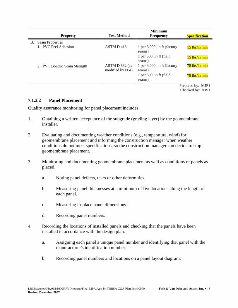
Property Test Method Minimum Frequency Specification
B. Seam Properties 1. PVC Peel Adhesion
ASTM D 413
1 per 3,000 lin ft (factory seams) 1 per 500 lin ft (field seams)
15 lbs/in min
15 lbs/in min
2. PVC Bonded Seam Strength ASTM D 882 (as modified by PGI)
1 per 3,000 lin ft (factory seams) 1 per 500 lin ft (field seams)
78 lbs/in min
78 lbs/in min
Prepared by: MJP1 Checked by: JOS1
7.1.2.2 Panel Placement Quality assurance monitoring for panel placement includes: 1. Obtaining a written acceptance of the subgrade (grading layer) by the geomembrane
installer. 2. Evaluating and documenting weather conditions (e.g., temperature, wind) for
geomembrane placement and informing the construction manager when weather conditions do not meet specifications, so the construction manager can decide to stop geomembrane placement.
3. Monitoring and documenting geomembrane placement as well as conditions of panels as
placed.
a. Noting panel defects, tears or other deformities. b. Measuring panel thicknesses at a minimum of five locations along the length of
each panel. c. Measuring in-place panel dimensions. d. Recording panel numbers.
4. Recording the locations of installed panels and checking that the panels have been
installed in accordance with the design plan.
a. Assigning each panel a unique panel number and identifying that panel with the manufacturer's identification number.
b. Recording panel numbers and locations on a panel layout diagram.

LJS\J:\scopes\04w018\10000\FVD reports\Final MPA\App I\r-TDRSA CQA Plan.doc\10000 Foth & Van Dyke and Assoc., Inc. • 19 Revised December 2007
7.1.2.3 Trial Seam Testing (Thermal Welded Seams) Items included in quality assurance monitoring of thermal welded field seams include the following: 1. Monitoring trial thermal welded seams constructed prior to each seaming sequence to
evaluate the seaming crew and equipment.
a. Record machine temperature, ambient temperature, machine speed, seamer identification, machine number, date and time for all trial seams.
b. Trial seams will be made at the beginning of each seaming period and at least
once every four hours, for each seaming apparatus used that day. Each seamer will make at least one (1) trial seam each day. Two specimens, 1 inch wide, will be cut from each end of the trial seam (i.e., four samples total). These samples are to be field-tested for shear and peel. Two (2) peel tests will be performed on the inside and outside tracks of the weld and two (2) shear tests will be performed. Alternate shear and peel tests so both tests are performed for each end of the trial seam.
2. Evaluating and documenting trial seam test results in accordance with the specifications
and accepting or rejecting seaming crews and/or equipment. 3. Evaluating and documenting the suitability of weather conditions (e.g., temperature,
wind, humidity) for seaming and informing the construction manager when weather conditions do not meet the specifications so the construction manager can decide to stop geomembrane seaming.
4. Observing and documenting seaming procedures and progress. 5. Assigning a seam number to each seam and recording seam construction data, including
seaming crew identification, date and time of seam construction, ambient temperature. a. Record the location of all seams on a seam layout diagram. 6. Confirming that the installer's field tensiometer has current calibration documentation.
At a minimum, the field tensiometer shall have been calibrated within 3 months prior to start of project.
7.1.2.4 Seam Testing and Repair Items included in the quality assurance for monitoring seam testing and repairs include the following: 1. Monitoring and documenting non-destructive testing done to evaluate continuity of all
field and factory-fabricated seams.
a. Observe seam air channel tests and air lance tests.

LJS\J:\scopes\04w018\10000\FVD reports\Final MPA\App I\r-TDRSA CQA Plan.doc\10000 Foth & Van Dyke and Assoc., Inc. • 20 Revised December 2007
b. Mark apparent failed seams for repair. c. Document seam repair and retesting. 2. Selecting locations where geomembrane samples will be taken to conduct destructive
testing. a. A minimum of one destructive test sample will be collected for every 500 lineal
feet of field seam. b. Locations of destructive test samples will be noted on a repair and sample
location diagram. 3. Monitoring the cutting of samples by the geomembrane installer. 4. Assigning a unique number to each sample and recording sample locations and other
pertinent observations made during sampling. 5. Monitoring the cutting of the sample in three parts: one for the geomembrane installer,
one for archiving, and one for testing by the off-site laboratory. 6. Monitoring and documenting the field seam destructive tests performed by the
geomembrane installer. 7. Labeling, packaging and shipping samples to the independent laboratory for destructive
testing. 8. Interpreting test results and accepting or rejecting seams based on off-site laboratory
testing results. Four (4) of five (5) tests per sample shall pass the minimum peel and shear requirements and the average of the five tests per sample must meet the minimum requirements.
9. Monitoring and documenting patching of holes caused by sampling. 10. Monitoring and documenting the non-destructive testing of the seams associated with
seam repair. 11. Monitoring and documenting the repair of the rejected seams and the non-destructive
testing of the seam repairs. a. Document passing seam tests between all destructive test locations. b. Record all seam repair locations. 12. Monitoring and documenting destructive testing related to seam repair. a. Monitoring and documenting one destructive seam sample for every 500 lineal
feet of repaired seam as described above.

LJS\J:\scopes\04w018\10000\FVD reports\Final MPA\App I\r-TDRSA CQA Plan.doc\10000 Foth & Van Dyke and Assoc., Inc. • 21 Revised December 2007
7.1.2.5 Defect Repairs The following quality assurance monitoring and testing will be implemented to monitor defect repairs: 1. Performing systematic visual observation of the entire surface of the geomembrane to
locate and document defects and indicate for each defect the type of repair that is required.
2. Monitoring and recording the repair of defects and the non-destructive testing of all
repairs. 3. Recording the location and the nature of all defect repairs. 7.1.2.6 Anchorage Testing Quality assurance associated with monitoring and testing of anchor trenches shall include the following: 1. Anchor trench excavation shall be monitored for proper depth and location. 2. Geomembrane panels extending into the anchor trench shall be monitored for complete
seaming within the anchor trench. 3. Anchor trench backfill operations will be observed and documented. a. The length of the open trench shall not exceed the amount of geomembrane to be
placed in one day. b. The depth of a typical anchor trench shall be documented to conform to approved
project drawings. c. Backfill shall be placed in lifts not to exceed one foot in loose thickness. a. Trench backfill shall consist of the soil excavated from the trench and compaction shall meet
or exceed the density of the adjacent material. 7.2 Documentation and Reporting
Documenting and reporting methods will be implemented to systematically record results of on-site monitoring and on-site testing. Reporting forms will be used for roll and panel placement, trial seam testing, panel seaming, non-destructive seam testing and destructive seam testing. Unique identifying numbers will be assigned to each panel and seam and used to reference the panel and seam location and test results. A geomembrane installer's certificate of acceptance of the subgrade will be obtained prior to placement of geomembrane panels.

LJS\J:\scopes\04w018\10000\FVD reports\Final MPA\App I\r-TDRSA CQA Plan.doc\10000 Foth & Van Dyke and Assoc., Inc. • 22 Revised December 2007
Panel location and seam location diagrams will be kept showing the location of all panels and seams, repairs and destructive sample test locations. These location diagrams will be updated on a daily basis and will be available for review by the construction manager. A photo log will be created containing photos of all phases of the geomembrane liner installation, including deployment, seaming, testing, and anchor trench construction. Copies of test results for all off-site laboratory testing will be forwarded to the on-site supervisor and will be made available to the construction manager. The laboratory test result documents will be maintained in a job file and submitted with the final documentation report.

LJS\J:\scopes\04w018\10000\FVD reports\Final MPA\App I\r-TDRSA CQA Plan.doc\10000 Foth & Van Dyke and Assoc., Inc. • 23 R Revised December 2007
8 Construction Observation - Miscellaneous Items
8.1 Geocomposite Drainage Layer
8.1.1 Geocomposite Rolls and Panels Construction quality assurance monitoring for the rolls and panels include: 1. Monitoring and documenting the unloading of trucks delivering geocomposite rolls to the
site. 2. Monitoring and documenting the handling and on-site storage procedures and location of
geocomposite rolls. 3. Review of manufacturer's QA testing for conformance with specifications. The
geocomposite and its components shall meet the property requirements stated below:
Property Test Method Minimum Frequency Specifications GEONET Thickness, minimum average ASTM D 5199 15,000 lbs 200 mil Polymer Density, minimum ASTM D 1505 200,000 lbs 0.940 g/cc Carbon Black Content ASTM D 4218 15,000 lbs 2 percent Carbon Black Disperson ASTM D 5596 45,000 lbs See note1 GEOTEXTILE Mass/Unit Area, minimum ASTM D 5261 20,000 sq. yards 10 oz/sq yards Grab Strength, minimum ASTM D 4632 20,000 sq yards 260 lbs Permittivity, minimum ASTM D 4491 1.0/sec 100,000 sq. yd AOS (095), maximum ASTM D 4751 80 sieve 100,000 sq. yd. GEOCOMPOSITE Transmissivity, minimum, including attached geotextiles2 ASTM D 4716 100,000 sq. yards 1 x 10⁻³ m2/sec Geonet/Geotextile adhesion3 ASTM D 413 100,000 sq. yards 1.0 lbs/inch
1 Carbon black dispersion for 10 different views: 8 of 10 in Category 1 or 2; and all 10 in Category 1, 2, or 3. 2 Manufacturing quality control transmissivity tests shall be measured using water at 20 degrees C with a gradiant of 0.1 under a normal pressure of 10,000 psf. A minimum seating period of 15 minutes shall be used. 3 Average of five equally spaced tests across the roll width.
4. Visual review and marking of the geocomposite as it is unrolled and deployed at the job
site for uniformity, damage, and imperfections, including holes, tears, punctures, and foreign matter.
8.1.2 Panel Placement
Quality assurance monitoring for panel placement includes: 1. Monitoring and documenting geocomposite placement as well as conditions of panels as
placed, including the following:

LJS\J:\scopes\04w018\10000\FVD reports\Final MPA\App I\r-TDRSA CQA Plan.doc\10000 Foth & Van Dyke and Assoc., Inc. • 24 R Revised December 2007
a. Noting panel defects, tears or other deformities. b. Orientation of panels as placed c. Anchorage procedures d. Documentation that cover materials are placed in a manner that prevents
damage to the geocomposite e. Documentation that each component of the geocomposite is secured to like
components of adjacent panels
8.2 Contact Water Collection and Extraction System
Survey documentation of the contact water collection and extraction system and other pipeline systems shall be completed as described in Section 3. Any aggregate material used as gravel drainage layer, and backfill or bedding in the trench or sumps shall be sampled and tested as described in Section 4.3 All materials and equipment shall be inspected prior to construction for conformance with the specifications and for any defects and/or flaws. All non-perforated pipe sections shall be air pressure tested following construction and backfilling. Pumps and controls shall be fully tested to assure all operational functions are working properly. 8.2.1 Installation The CQA officer shall inspect all prefabricated structures for conformity with design specifications and for conformity with design specifications and for defective manufacturing. Additionally, the following CQA activities will be performed during contact water collection and extraction system installation:
1. Full-time observation to ensure that the underlying liner components are not damaged by collection system installation
2. Documentation that the collection pipe location and invert elevations are in accordance with project specifications
3. Documentation that pipe joining procedures are in accordance with project specifications 4. Documentation that fill materials placed around the collection piping are in accordance
with project specifications 5. Documentation that the collection sump and the underlying leak detection sump are
constructed in accordance with project specifications 6. Documentation that the collection and leak detection sumps’ sideslope risers, associated
extraction pumping equipment, and controls are installed in accordance with project specifications
7. Documentation and testing of backfilling procedures during installation of the double encased forcemain to the contact water basin.
8. Documentation that the piping is not damaged during cover material placement 9. Documentation of extraction systems, field test demonstrating system, operational
readiness, including pumps, pressure meter control, values, etc.

LJS\J:\scopes\04w018\10000\FVD reports\Final MPA\App I\r-TDRSA CQA Plan.doc\10000 Foth & Van Dyke and Assoc., Inc. • 25 Revised December 2007
9 Construction Observation Report
9.1 Documentation
Upon completion of the construction of each major phase and prior to placing in service, the CQA officer shall submit a documentation report to the MDEQ. This report contains, at a minimum, the following information:
♦ Certification by a professional engineer, registered in the State of Michigan, that, based on his/her knowledge and review of the construction records, the construction has been performed in substantial conformance with the engineering plans and specifications.
♦ Detailed narrative describing the construction events in chronological order and results of the quality assurance testing.
♦ Daily field reports prepared by the on-site CQA technician.
♦ Field and laboratory test data relevant to subgrade preparation.
♦ Field and laboratory test data relevant to installation of geosynthetic components of the liner (GCL, geomembrane, geotextile)
♦ Field and laboratory test data relevant to installation of the contact water collection and extraction system
♦ Discussion of any construction material or equipment which deviated from the engineering plans and specifications, reasons for deviation, methods to bring the deviation into compliance, and approval of deviations by the MDEQ.
♦ Photographs documenting all aspects of construction.
♦ Record drawings, sealed by a licensed professional engineer, documenting the “as constructed” elevations of the various components of the construction (± 0.5 feet), locations of field testing performed, geomembrane panel layout, and cross sections of the construction.
♦ Information required by Part 115, Administrative Rule 299.4921.

J:\scopes\04w018\10000\FVD reports\TDRSA Leak Det Syst Plan\R-text.doc
Appendix B
Leak Detection System Inspection and Monitoring Forms

J:\scopes\04w018\10000\FVD reports\TDRSA Leak Det Syst Plan\R-text.doc
Leak Detection System Inspection and Monitoring Form Kennecott Eagle Minerals Company
Inspector:
Date:
Inspection Results
Liquid in LDS Sump:
yes no Gallons Pumped from LDS Sump:
Liquid Sampled: yes no
Date Sampled:
Field pH: Laboratory Sulfate Result:
Is the volume pumped greater than
150 gallons and the sulfate result greater than 500 mg/L? If yes, this
is a reportable condition: Yes ______ No _____
Recommended Actions
Follow-up of Previously Recommended Actions
Date of Next Inspection:
Archive Inspection Form Until: (5 yrs from date of inspection)

J:\scopes\04w018\10000\FVD reports\TDRSA Leak Det Syst Plan\R-text.doc
Leak Detection System Inspection and Monitoring Log Kennecott Eagle Minerals Company
Date
Liquid Present in Sump (y/n)
Field pH
Laboratory Sulfate (mg/L)
Gallons of Liquid Pumped from LDS
Sump Recommended/Implemented Actions Initials

Plan
Eagle Project Impermeable Surface Inspection and Surface Repair Plan Project I.D.: 04W018
Kennecott Eagle Minerals Company Michigamme Township, Michigan
December 2007

Eagle Project
Impermeable Surface Inspection and Surface Repair Plan
Project ID: 04W018
Prepared for Kennecott Eagle Minerals Company
ISO 14001:2004 Registered System
Prepared by Foth Infrastructure & Environment, LLC
December 2007
Foth Infrastructure & Environment, LLC 2007 2737 South Ridge Road, Suite 600 • P.O. Box 12326 • Green Bay, WI 54307-2326 • (920) 497-2500 • Fax: (920) 497-8516

LJS\J:\scopes\04w018\10000\FVD reports\Imp Surf Insp Plan\R-text.doc ii
Eagle Project Impermeable Surface Inspection and
Surface Repair Plan
Contents Page 1. Impermeable Surface Inspection and Surface Repair Plan .....................................................1
1.1 Introduction....................................................................................................................1 1.1.1 The COSA..........................................................................................................1 1.1.2 Truck Wash Area ...............................................................................................1 1.1.3 Bituminous Surfaced Areas ...............................................................................1
1.2 Site Inspections and Monitoring ....................................................................................2 1.2.1 COSA.................................................................................................................2 1.2.2 Truck Wash Area ...............................................................................................2 1.2.3 Bituminous Surfaced Areas ...............................................................................2
1.3 Repair Methods..............................................................................................................2 1.3.1 Concrete Areas...................................................................................................2 1.3.2 Bituminous Surfaced Areas ...............................................................................3
Figures Figure 1 Contact Area Impermeable Surface
Appendices Appendix A Impermeable Surface Inspection Log

LJS\J:\scopes\04w018\10000\FVD reports\Imp Surf Insp Plan\R-text.doc Foth Infrastructure & Environment • 1
1. Impermeable Surface Inspection and Surface Repair Plan
1.1 Introduction
This Impermeable Surface Inspection and Surface Repair Plan has been prepared to address integrity monitoring of impermeable surfaces that will be exposed to contact storm water. The monitoring plan includes frequency of inspection and action plans for surface repair, along with a sample inspection log documenting the date of inspection, identification of the inspector, results, and required follow-up action. Inspection documents will be kept on site. Figure 1 indicates impermeable surface areas with potential for exposure to contact water. Areas covered under this plan include:
♦ Coarse Ore Storage Area (COSA). ♦ Truck Wash Area. ♦ Bituminous Surfaced Areas.
Other areas with impermeable surfaces with potential for exposure to contact water include the temporary development rock storage area (TDRSA), the fuel storage area, and the contact water basins (CWB). These areas will be monitored under separate plans. 1.1.1 The COSA The COSA will be constructed to contain mined ore awaiting processing. The COSA building will measure approximately 1,394 m2 (15,000 ft2) having a storage capacity of 3,000 m3 (3,924 yd3). This building will be enclosed on three sides and constructed of steel framing with steel siding. A clear plastic drop door will be installed across the open side to minimize precipitation contact with the ore and reduce particulate release. The floor of the COSA will be constructed of 12-in thick reinforced concrete sloping to a catch basin for collection of contact water. To minimize potential reinforcement steel corrosion, the reinforcement will be epoxy-coated. Any collected contact water will be pumped to the CWB for treatment. A vapor barrier will be installed below the concrete floor to provide additional moisture retention. 1.1.2 Truck Wash Area Ore transport trucks leaving the main operations area will be required to go through a truck wash prior to leaving the facility. The truck wash, an approximately 4,000 square foot facility, will be an enclosed system that recycles the wash water. Solids will be removed from the wash water using a series of cyclone separators. 1.1.3 Bituminous Surfaced Areas Bituminous surfaced areas will be constructed in the areas shown on Figure 1. These areas are generally located in the southern part of the main operations area and include the roadway from the mine portal to the COSA facility, the crusher and crushed ore bins area, laydown area, and the entrance to the truck wash. The bituminous areas will consist of 4-inches of bituminous concrete supported by 12-inches of road aggregate.

LJS\J:\scopes\04w018\10000\FVD reports\Imp Surf Insp Plan\R-text.doc Foth Infrastructure & Environment • 2
1.2 Site Inspections and Monitoring
1.2.1 COSA KEMC personnel will provide monthly inspections of the COSA floor slab during time periods when ore is stored in the facility. Areas of the COSA which do not contain ore will be inspected and repaired as necessary. Then, ore will be moved to these previously inspected/repaired areas and the exposed portion of the COSA floor inspected and repaired as necessary. Staging of inspections as described herein will be performed until the entire COSA floor area is evaluated. To evaluate the catch basins in the COSA, any standing liquid will be removed and properly disposed of, and the catch basins inspected for any potential areas of leakage or cracking. KEMC personnel will complete monthly inspection logs outlining dates of inspection, identification of the inspector, results, and required follow-up action. A sample inspection log is included in Appendix A. 1.2.2 Truck Wash Area KEMC personnel will provide monthly inspections of the truck wash concrete pavement during mining operations. Catch basins will be evaluated by removing standing liquid and visually inspection the basin for leaks and cracks. Monthly inspection logs (Appendix A) will be completed during the inspections. 1.2.3 Bituminous Surfaced Areas Bituminous surfaced areas will be inspected on a monthly basis. KEMC personnel will observe the pavement for cracking and other pavement surface problems that may compromise its impermeability or develop into potholes, such as alligatored areas, which are interconnecting cracks forming a series of blocks resembling alligator skin. KEMC personnel will complete monthly inspection logs outlining dates of inspection, identification of the inspector, results, and required follow-up action. Repairs will be performed in a timely manner. 1.3 Repair Methods
1.3.1 Concrete Areas Once identified, cracks that have the potential to provide a conduit for contact water transmittal will be sealed by methods appropriate to their size. Based on the size of the crack, repairs will be conducted by one of two methods: routing and epoxy troweling, and epoxy grouting. Cracks that are less than 1/8-inch in width will be considered Class 1 cracks; cracks greater than 1/8-inch in width will be considered Class 2 cracks. Class 1 cracks will be repaired by routing and epoxy troweling. Routing of the crack consists of routing the crack with a concrete saw or other hand or pneumatic tool, to open the crack sufficiently to receive the sealant. A minimum routed width of ¼ - inch is desirable since smaller

LJS\J:\scopes\04w018\10000\FVD reports\Imp Surf Insp Plan\R-text.doc Foth Infrastructure & Environment • 3
openings are difficult to fill. The surface of the routed crack will be cleaned and allowed to dry. Epoxy sealing will then be troweled into the crack. Separation of the floor slab from the perimeter wall/foundation of the COSA will generally be treated as Class 1 cracks and filled by epoxy troweling. Class 2 cracks will be repaired by epoxy injection. This method generally consists of drilling holes at close intervals in the crack and injecting epoxy under pressure. This fills the crack entirely to provide a good seal. Larger areas where mechanical damage has occurred may require removal and replacement with new concrete. In these areas, the damaged area will be cut out and removed, new reinforcement bars drilled and grouted into the existing concrete, and a new section of concrete placed. 1.3.2 Bituminous Surfaced Areas As with concrete pavement, repair methods for cracks in bituminous surfaced areas will vary with the size of the crack as described below:
♦ Minor Cracks: Minor cracks are less than ¼-inch wide and can generally be filled with an asphalt emulsion sealer.
♦ Structural Cracks: Structural cracks are cracks between ¼-inch and 1-inch wide. These will generally be sealed with a hot elastomeric-type crack sealant.
♦ Cracks wider than 1-inch: Cracks wider than 1-inch will be patched with hot mix asphalt. Prior to repair, the cracks will be cleaned with compressed air, or other appropriate method, to remove deleterious material. Cracks between ¼-inch and ½-inch wide will be routed to a minimum of ½-inch by ½-inch in shape. The cleaned cracks will be sealed with the elastomeric sealant or hot mix asphalt, depending on size, and allowed to cure prior to exposure to traffic.

LJS\J:\scopes\04w018\10000\FVD reports\Imp Surf Insp Plan\R-text.doc
Figures

445
445
445
445
447 4
47
PILE
PILES
PILES
444
446
445
444444
445
444
444
447
446
446
445445
445SCATTERED TREES
SCATTERED TREES
442
443
442
442
443
443
SCATTERED TREES
454
453
452
451
450
449
448
447
446
455456
457
442
442
442
444
437
436438
439
440
441
443
SCATTERED
TREES
SCATTERED
TREES
CO
. RD
. AA
A
SCATTERED TREES
SCATTERED TREES
437
438439440
442
436
441
443
444
435
435
PILE
PILEPILE
PILE
TRU
CK
WA
SH
CONTACT
SNOW PILE
ROAD EASEMENT
LAYDOWN
AREA
UNDERGROUND
DAY STORAGE
CHAIN LINK
PERIMETER FENCE
GENERATOR PLANT
NON-
CONTACT
SNOW
PILEGATE
GATE
EFFLUENT
PIPELINE
NON-CONTACT
AREA
PROPANE STORAGE
CONSTRUCTION STAGING AREA
AND SOIL STOCKPILE AREA
GATE
HOUSE
LOADING
DOCK
WAREHOUSE
TRUCK
SCALE
SCREENING
BERM
TREATED WATER
INFILTRATION SYSTEM
TEMPORARY
DEVELOPMENT
ROCK STORAGE AREA
CO
VE
RE
D
CO
AR
SE
OR
E
ST
OR
AG
E
ROAD PUBLIC ACCESS
CO
. RD
. AA
A
VISITOR
PARKING
EMPLOYEE
PARKING
CONTACT
WATER
BASIN #1
CONTACT
WATER
BASIN #2
MINE SITE
ACCESS ROAD
EMERGENCY
RESPONSE FACILITY
NON-POTABLE
WATER STORAGE
TANK
CONTACT
PUMP STATION
CONTACT
PUMP STATION
FUEL
STORAGE
SCREENING
BERM
MINE AIR HEATER
MAINTENANCE SHOP
& COMPRESSOR PLANT
ASSAY
LAB
SCREENING
BERM
NON-CONTACT
WATER
INFILTRATION
BASIN #3
NON-CONTACT
WATER
INFILTRATION
BASIN #4
CRUSHED
ORE BINS
PORTAL
CORE
STORAGE
CRUSHER
RAMP
AND DUMP
CONVEYOR
CRUSHER
MINE DRY/
OFFICE
SEPTIC
SYSTEM
WASTEWATER
TREATMENT PLANT
X
X
X
X
X
X
X
X
X
XX
X
XX
XX
XX
XX
XX
XX
XX
XX
X X X X X X X X X X X X X X X
X
X
X
X
X
X
X
X
X
XX
XX
XX
XX
XX
XX
XX
QAL028A
QAL008A
QAL008D
QAL026A
QAL027A
QAL029A
QAL029D
QAL031D
QAL041D
jow
L:\04W018\MPA\4w18fig1.dgn
12/13/2007
Scale: Date:
REVISED DATE BY DESCRIPTION
CHECKED BY:
APPROVED BY:
APPROVED BY:
DATE:
DATE:
DATE:
JOS1
SVD1
04W018
Foth Infrastructure & Environment, LLC
Prepared By: Project No.
DEC. ’07
DEC. ’07 DECEMBER, 2007
LEGEND
UNPAVED ROAD
TREEPLANIMETRIC WETLAND NOTATION
NOTES:
1.
2.
3.
4.
PERIMETER FENCE
5,177,200 N
5,177,400 N
5,177,600 N
5,177,800 N
432,200 E 432,400 E 432,600 E 432,800 E
CONTOUR INTERVAL BASED ON NORTH AMERICAN VERTICAL DATUM OF 1988.
HORIZONTAL DATUM BASED ON NAD 83/94.
HORIZONTAL COORDINATES BASED ON UTM ZONE 16.
60M0 120M
TOPOGRAPHIC AND PLANIMETRIC DATA SUPPLIED BY AERO-METRIC ENGINEERING,
SHEBOYGAN, WISCONSIN. DATE OF PHOTOGRAPHY:JUNE 2, 2004.
5.
TREE LINE
ROAD EASEMENT PROVIDE BY
MCINTOSH ENGINEERING, INC.,
AUGUST, 2005
TREATED WATER
INFILTRATION SYSTEM
X X
SURFACE PROPERTY BOUNDARY AS OF NOVEMBER 18, 2004
SUPPLIED BY KENNECOTT VIA
GOLDER & ASSOCIATES INC., AUGUST, 2005.
GJB
SITE LOCATION: PROJECT SITE WITHIN SECTIONS 11 & 12,
T50N, R29W, TOWN OF MICHIGAMME, MARQUETTE COUNTY, MICHIGAN.
KENNECOTT PROPERTY BOUNDARY
MINE PLAN DATA ADAPTED FROM MCINTOSH ENGINEERING, INC.,
TEMPE, ARIZONA.
EXISTING ELEV. CONTOUR IN METERS MSL
BITUMINOUS LINED OPERATIONS AREA
MAIN OPERATIONS AREA
FIGURE 1
CONTACT AREA IMPERMEABLE SURFACES
TRUCK WASH
COSA

LJS\J:\scopes\04w018\10000\FVD reports\Imp Surf Insp Plan\R-text.doc
Appendix A
Impermeable Surface Inspection Log

LJS\J:\scopes\04w018\10000\FVD reports\Imp Surf Insp Plan\R-text.doc
Impermeable Surface Inspection Form Kennecott Eagle Minerals Company
Inspector: Concrete Pavement Date: Inspection Area:
Inspection Results
Recommended Actions
Follow-up of Previous Recommendations
Date of Next Inspection:
Archive Inspection Form Until: (5 yrs from date of inspection)
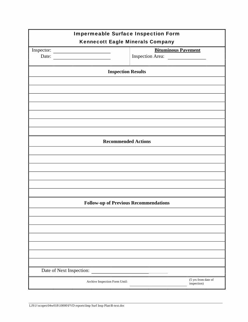
LJS\J:\scopes\04w018\10000\FVD reports\Imp Surf Insp Plan\R-text.doc
Impermeable Surface Inspection Form Kennecott Eagle Minerals Company
Inspector: Bituminous Pavement Date: Inspection Area:
Inspection Results
Recommended Actions
Follow-up of Previous Recommendations
Date of Next Inspection:
Archive Inspection Form Until: (5 yrs from date of inspection)

Plan
Eagle Project Topsoil Management Plan Project I.D.: 04W018
Kennecott Eagle Minerals Company Marquette, Michigan
December 2007

LJS\J:\scopes\04w018\10000\FVD reports\Topsoil Mgmt Plan\R-text.doc ii
Eagle Project Topsoil Management Plan
Contents
Page 1. Introduction .............................................................................................................................1
1.1 Purpose...........................................................................................................................1 2. Topsoil Management ...............................................................................................................2
2.1 Topsoil Stripping and Stockpiling .................................................................................2 2.2 Potential Long-Term Effects of Topsoil Stockpiling.....................................................2 2.3 Topsoil Management Plan .............................................................................................2
3. References ...............................................................................................................................4
Figures Figure 1 Site Development Plan and Topographical Map

LJS\J:\scopes\04w018\10000\FVD reports\Topsoil Mgmt Plan\R-text.doc Foth Infrastructure & Environment • 1
1. Introduction
1.1 Purpose
This Topsoil Management Plan has been prepared to address the potential effects of long-term storage of topsoil in stockpiles, and Kennecott Eagle Minerals Company (KEMC) methods to segregate and re-spread the topsoil during mine site reclamation. Additionally, this plan presents KEMC’s plan to achieve a topsoil thickness and fertility commensurate with pre-construction activities.

LJS\J:\scopes\04w018\10000\FVD reports\Topsoil Mgmt Plan\R-text.doc Foth Infrastructure & Environment • 2
2. Topsoil Management
2.1 Topsoil Stripping and Stockpiling
As discussed in the Mine Permit Application (Foth, 2006), average topsoil thickness at the site is approximately 3 inches. The quantity of topsoil to be stripped from the site during project construction is estimated at approximately 28,600 cubic yards (yd3). Approximately 11,400 yd3 of topsoil will be used on-site during construction to revegetate the disturbed areas, resulting in approximately 17,200 yd3 to be stockpiled in the on-site topsoil stockpile area (Figure 1). The topsoil stripping and stockpiling will be completed using conventional earth-moving equipment such as bulldozers, scrapers, graders and off-road trucks. In areas where the topsoil is relatively thin, the contractor will remove the topsoil using smaller equipment to minimize mixing of topsoil and subsoils. Topsoil will be stockpiled in a controlled manner in the topsoil stockpile area. The stockpile will be surrounded by silt fencing or similar erosion control devices to prevent soil erosion until permanent erosion control measures are installed. Permanent measures include establishment of vegetation. Topsoil stockpiles will be seeded with a Michigan Department of Transportation (MDOT), 2003 Standard Specification for Construction (MDOT, 2003) Temporary Seed Mixture 24+ (TSM 24+). TSM 24+ includes a 50/50 mixture of Perennial Ryegrass and Spring Oats. The rye and oats will quickly establish vegetation on the stockpile and mitigate soil erosion and dust emissions. 2.2 Potential Long-Term Effects of Topsoil Stockpiling
During long-term stockpiling of soils, changes can occur below depth for sandy textured soils such as those present at the site. Potential changes could be a reduction in the content of available nutrients, pH and organic matter levels. 2.3 Topsoil Management Plan
To minimize the detrimental effects of long-term storage of topsoil in stockpiles, KEMC will implement the following procedures.
♦ Following stockpiling, KEMC will collect up to four samples (1 sample/5,000 yd3 of topsoil stockpiled) of the topsoil for analysis, and test for pH, nitrogen, and organic content to establish an initial nutrient composition of the topsoil.
♦ As a temporary soil erosion and control measure, silt fences or similar erosion control
devices will be installed surrounding the stockpiles to prevent soil erosion. For permanent soil erosion control, topsoil stockpiles will be seeded. In accordance with the facilities soil erosion sedimentation and control plan (Foth, 2007) to establish a vegetative cover and minimize erosion and dust emissions.
♦ Prior to use of the topsoil for reclamation, KEMC will collect samples of the topsoil for
analysis, including pH, nitrogen, and organic content and compare these results to the initial condition. If required, soil amendment will be performed before re-spreading the topsoil to mitigate any deficiencies in the topsoil so that the topsoil is productive and a topsoil thickness and fertility commensurate with pre-construction activities is achieved.

LJS\J:\scopes\04w018\10000\FVD reports\Topsoil Mgmt Plan\R-text.doc Foth Infrastructure & Environment • 3
Fertilizer application rates will be established upon evaluation of the soil nutrient content. If needed, additional similar quality topsoil will be purchased to meet reclamation needs.
♦ KEMC will re-spread topsoil in those areas requiring reclamation, to approximate pre-
development thicknesses of approximately 3 inches using scrapers and bulldozers, as required.
♦ Vegetation establishment will proceed in accordance with the Mine Reclamation Plan
and Mine Permit requirements.

LJS\J:\scopes\04w018\10000\FVD reports\Topsoil Mgmt Plan\R-text.doc Foth Infrastructure & Environment • 4
3. References Foth Infrastructure & Environment, LLC. Eagle Project Part 91 Soil Erosion and Sedimentation
Control Permit Application Main Facility. July 2007 Foth & Van Dyke and Associates, 2006. Eagle Project Mining Permit Application (submitted to
Michigan Department of Environmental Quality in February 2006). Michigan Department of Environmental Quality. General Permit Conditions Non Ferrous
Metallic Mineral Mining Permit No. MP 01 2007. Anticipated Issuance Date of December 14, 2007.
Michigan Department of Transportation, 2003. Standard Specification for Construction.

LJS\J:\scopes\04w018\10000\FVD reports\Topsoil Mgmt Plan\R-text.doc
Figures


Plan
Eagle Project Portal Abandonment Plan Project No.: 04W018
Kennecott Eagle Minerals Company Marquette, Michigan
December 2007

Eagle Project
Portal Abandonment Plan
Project ID: 04W018
Prepared for Kennecott Eagle Minerals Company
ISO 14001:2004 Registered System
Prepared by Foth Infrastructure & Environment, LLC
December 2007
Foth Infrastructure & Environment, LLC 2007 2737 South Ridge Road, Suite 600 • P.O. Box 12326 • Green Bay, WI 54307-2326 • (920) 497-2500 • Fax: (920) 497-8516

LJS\J:\scopes\04w018\10000\FVD reports\Portal Aband Plan\r-text.doc ii
Eagle Project Portal Abandonment Plan
Contents
Page 1 Portal Abandonment Description ............................................................................................1
Figures Figure 1 Portal Abandonment

LJS\J:\scopes\04w018\10000\FVD reports\Portal Aband Plan\r-text.doc Foth Infrastructure & Environment • 1
1 Portal Abandonment Description As part of the Mine Reclamation Plan, the mine portal abandonment will be performed in the following manner:
♦ The portal installed to provide access to the decline during mine operations will be removed.
♦ Boulders of development rock will be placed inside the portal a distance of
approximately 30 feet from the portal entry (Figure 1).
♦ A two foot thick plug of concrete will be installed over the face of the development rock boulders. At the top where the installation joins with the natural outcrop at ground level, rock pieces from the outcrop will be embedded to a depth of two feet below grade level (Figure 1).
♦ Once the concrete is set and the portal plug is complete, backfilling with clean fill of the
area up to the surrounding area grade level will be performed.

LJS\J:\scopes\04w018\10000\FVD reports\Portal Aband Plan\r-text.doc
Figures
