john noble perkins thesis submitted to the graduate ... · problem of aerodynamic heating tends to...
TRANSCRIPT

THE EFFECT OF HEAT I'-!SULATION ON THE
COOLD\G REQUIREMENTS OF THE INTERNAL
STRUCTURE OF HIGH-SPEED VEHICLES
by
John Noble Perkins
Thesis submitted to the Graduate Faculty of the
Vir~inia Polytechnic Institute
:in candidacy for the degree of
MASTF.R OF SCIID·lCE
in
Aeronautical Engineering
APPROVED: APPROVED:
Director of Graduate Studies Head of Department
Dean of Engineering Supervisor or Ma,ior Professor
April 29, 1958
Blacksburg, Virginia

-2-
TABLE OF CONT~!TS
Page
1. INTRODUCTIOn • • • • • • • • • • • • • • • • • • • 5
2. DETERMINATION OF TIWJSIEHT SKrn T:FJ.WERATURES • • • 9
2.1 Governing Equations • • • • •••••• 2.2 Determination of Parameters ....... 2.3 Ru.rige-Kutta Hethod of Numerical.
9
14
Integration • • • • • • • • • • • • • • 20
2.4 E:xa.rnple Problem • • • • • • • • • • • • 23
3. DErERI·!INATIOIJ OF TRANSIFl·!T Tm.IPmATURE VARIATIOH
IT! INSULATI0rJ • • • • • • • • • • • • • • • • • • Z7
3.1 Introduction • • • • • • • • • • • • • • Z7
Heat Transfer in Insulation •••••• Governint: Equations • • • • • • • • • • •
Initial and Boundary Conditi.ons • •••
Finite-Difference l-!ethod of Solution ••
E:.lcar.ple Problem • • • • • • • • • • • •
DISCUSSIOli OF RESULTS • • • • • • • • • • •
4.1 AssUlned Trajectories • • • • • • •
• • •
• • • Co~pressibility Effects • • • • • • • •
Comparison of Two- and Three-Dimensional
Solutions • • • • • • • • • • • • • • •
Effect of Skin Thickness • • • • • • • •
28
29
33
35
37
42
l.i.2
42

-3-
Jla~ts •••• • ••••••••
Iuulation • • • • • • • • • • • • • • 4.7 lacoimtan4&tions ••• • • • •••••
; • CONCLUSIONS • • • • • • • • • • • • • • • • • •
6. SUMMARY • • • • • • • • • • • • • • • • • • • •
7• A~ • • • • • • • • • • • • • • • •
8. BISLIOOKAPHY • • • • • • • • • • • • • • • • • •
9." VITA •• • • • • • • • • • • • • • • • • •" • • •
46
47 49
51 5, 54
;a

FIGURE 1
FIGURE 2
FIGURE 3
FIGURE 4
FIGURE 5
FIGURE 6
FIG!J'RE 7
FIG1JRE t1
FIGURE 9
FIGURE 10
FIGURE 11
-4-
LIST OF FIGURES
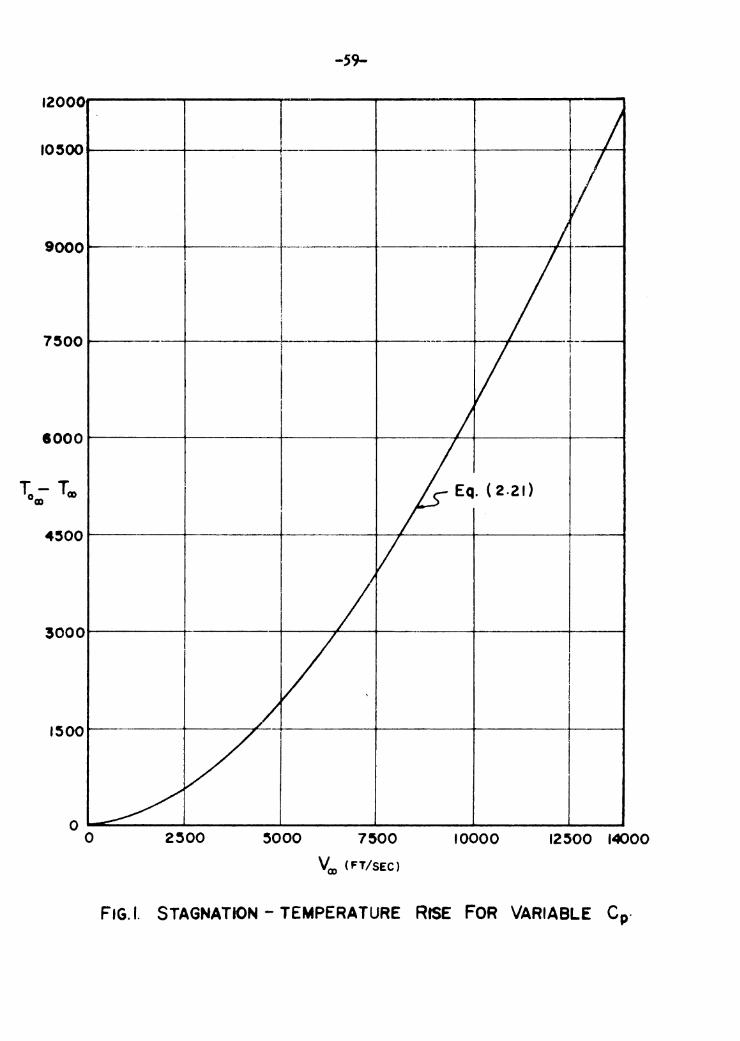
Stagnation-Temperature Rise for Variable Cp • • • • • • • • • •
Mach Humber and Altitude Dia[;ram (Trajectory !Jo. 1) •••••••
1:Ia.ch ;<Jumber and Altitude Diagram (Trajectory i:o. 2) • • • • • • •
Mach Number and Altitude Diagram (Trajectory t.ro. 3) •••••••
Time History of Skin Temperature (Trajectory No. 1) • • • ••••
Time History of Skin Temperature (Tra~iectory No. 2) •••••••
Time HistoriJ of Skin Temperature (Trajectory No. 3) •••••••
• • • • • •
••••••
••••••
• • • • • •
• • • • • •
• • • • • •
• • • • • •
Co2parison of Two-Dimensional Solution for Skin Temperatures with Three-Dj_mensional Solution (Trajectory No. 3) ••••••••
Temperature Variation in Insulation (Trajectory ri!o. 1) • • • • • • • • • • • • • Temperature Varj_ation in Insulation (TrajectOr1J No. 2) • • • • • • • • • • • • •
Temperature Variation j_n Insulation (Trajectory lJo. 3) • • • • • • • • • • • • •
Page
59
60
61
62
63
64
65
66
67
68
69

-5-
1. 1'.·lTRODUCTIO':
As actual and proro~ed speeds a.c:d alt~tudes of flit:ht
:Lncrease, the rrohlett of :na:inta:i-:1in~~ the ternr-erature of the
inter:1al structure of high-speed vehicles W:.thin structurally
perr:-,:i_ssable vnlues becor:ies :increas:ir::~ly d::fficult. Due to
aerodyn.a::ic heating, the internal terr:pera.tures of an aircra;."'t
travell r:{~ throu"'.h the atnoaphere at hi ch I:nch nm.ibers r;iay
becor;e excess:i ve unless a sufficient ar,i;mnt of cool inc is
supplied. As an example of one of the d:ifficult1es caused ry
aerodY'1a;.i.:ic heat:i ng, j t is known that sone of the Ger1ran A-4
r:~iss:1les experienced sufficient internal heating tc cause
exi:1csion of the fuel tru:ks rrior to iwract.
In attem:ptinc to solve the therrial prollem, it is first
necessary to determir1e the rate a.t which heat enters the
surface, and second, to provide some nea:·it3 wMch will prevent
the heat fron becord.ng excessive in the internal structure of
the vehicle.
The problem of deter;1d.ni';;~ the theoretical heat-transfer
cha.racter5 sties date back to the work of Pohlhausen27 and
L. Crocco28• In 1935 and a[c~ain :i.n 1938 von Yarman treated the
29 JO sulject of heat transfer for la.'Tdnar t-0undar::r layers ' ·•
Lore recently, the "WOrks by Huston, ,.,a.rfi.eld, and Stone31 , by
6 2 1 Lo , ty Van Driest , and by Truitt have all extended the

-6-
knowledee of heat-transfer characteristics for both laminar
and turbulent boundar'J layers. The nethod presented in this
thesis for determining the skin temperatures will be based
ma.inly on the work of these authors.
In order to un.derstand the fundamentals of aerodynamic
heating, it is first necessary to introduce some fundamental
concepts. As its na.m.e implies, aerodynamic heating is the
heating of an object as a result of the flow of air at high
speed about that object. Friction between the fluid filaments
as they stream along the body and compression at and near the
stagnation regions of forward surfaces convert the kinetic
energy of notion into heat within a thin layer of air
surrounding the body. The temperature of this layer increases
with the square of the speed so that, already at a Ha.ch number
of 5, the boundary layer temperature attains a vnlue of
approximately 3000 °R. Since this temperature j_s concentrated
j_n the air at the surf ace of the aircraft, heat will flow
readily from the boundary layer to the aircra~, the ease with
which it flows increasing also with the speed. Therefore, the
problem of aerodynamic heating tends to increase jn severity as
the speed increases. This fact :i.s aptly pointed out jn the
following quotation from reference 21
''Because of the increase of heat transfer with speed, it
arrears that a ••thermal barrier•' exists much as it

-7-
appeared in the past that a ''sonic barrier'' existed. The
problems differ somewhat in that the sonic barrier existed
over a narrow band of Mach number, whereas the thermal
barrier does not occur over a limited range of Mach number
but rather tends to increase in severjty as the }fa.ch number
is increased. t' vihile, as in the case of the sonic barrier, proper design
can alleviate some of the problems arising from the thermal
barrier, it is obvious that as flight speeds become very large
(say, of the order of Mach numbers of 15 and greater) 1 the
surface temperatures w:ill become very high under any design
condition. Thus, it appears that the surfaces of high-speed
vehicles will have to be made of some material, such as ceramics,
which can withstand the high temperatures to which they will be
subjected.
Assuning, then, that the surface temperature will be very
large, the problem of keeping the temperature of the internal
structure from becorrQng excessive arises. This problem has
several possible solutions. Certainly, for flights of long
duration at very high speeds, some form of internal cooling will
be required. However, since weight is always of prime iinFOrtance
in the desir,n of any aircraft, the weight of a cooling system,
capable of handling the large temperatures encountered at flight
speeds of Mach nw:ibers of 15 or greater, may prove to be excessjve.

_g_
With this in mind, it was suggested by Dr. J. F. Vandrey,
Advanced Design Section, The Martin Company, that heat insulation
be used to prevent a portion of the heat from reaching the
internal structure of the vehicle. It is expected that, while
this will not eliminate the need for internal cooling, it will
make possible the use of a n1uch smaller, and thus lighter,
cooling system.
It was, therefore, the purpose of this thesis to perform a
theoretical analysis to determine the skin temperatures obtained
by a missile throughout several trajectories, and then to
ascertain the amount of heat transferred through a blanket of
insulation placed between the skin and the internal structure
of the vehicle.

-9-
2. DE.'Tm.HI>lATIO: l OF TRASSIN:T SKI\l TFl:PEllATURES
2.1. Governinp: :§guations. F'or aerodynamic heating
problems, the local rate of heat transfer iEto (or out of) an
element of s1dn is equal to the local aerodynamic heat-transfer
rate at the element 1:d.nus the heat-transfer rate on the eler:ient
that is lost by radiation plus the equipment heat-release rate
rlus the heat-transfer rate into the element due to solar
radiation. This statement nay be expressed symbolically as
(2.1)
where Qlocal is the local rate of heat-transfer, in :BTU/sec,
at the sk5n elerner:t 6 A. This, :i.n turn, nay l.e rewritten as
wbere
dT 6 A c ts w ......!'! ,
dt
') ~ A = local element of surface area, (ft ... )
(2.2)
c = speci.fic heat of skin material, (BTU/lb-0 R)
ts = skin th:ickness, (ft)
w = srecific we1[>,ht of skin r:iaterial, (lb/ft3)
T = outer surface skin terr~perature, (0 R) w t = tine, (sec) •
The riua.:1t:it:y qa is the aerodynarrd.c heat-transfer rate, ir:
I?TU/sec, which may be wrjtten as

-10-
q = .6 A h (T - T ) ·a aw w , (2.3)
where h = film coefficient of heat tra.'1sfer,
(BTU/sec-ft2-°R)
Taw = adiabatic wall temperature, (0 R) •
The term ~ is the heat transfer rate lost by radiation from the
elemental surface, .6 A, in BTU/sec, and may be written as
where
(2.4)
€ = total hemispherical emissivity of the surface,
(dimensionless)
o = Stefan-Boltzmann radiation constant,
(BTU/sec-~2-0R) •
Usually in a continuum. flow the solar radiation term can
be neglected1 (i.e., q = O). Since the need for cooling s equipment is not known until a preliminary estimation of skin
temperature is made, the equipment heat release term is also
omitted. Therefore, the governing equation for the heat transfer
process is, from Eq. (2.1),
~ 4 6. A c t w --.Jal: == .6 A h (Ta;w- - Tw) - .6 A € o Tw • s dt (2.5)
Defining G = c ts w, as the heat absorption capacity of the skin
material, Eq. (2.5) can be restated as

-11-
dT...,. h €<1 Tw4 - = - (T - Tw) - , dt G aw G
(2.6)
wherein the aerodynamic heat-transfer rate (Eq. (2.3)), per
unit area, in °R/sec, is
~ = ~ (T - T ) G G aw w • (2.7)
!~ote that Eq. (2.7) says that the direction of heat flow at the
skin surface does not depend on the difference between the wall
temperature, T...,., and the local free-stream temperature, T00, but
on the difference between the wall temperature and the adiabat:i.c
wall ter1perature, Ta.w•
The film coefficient of heat transfer, h, can be expressed
in terms of the Stanton nmnber2, Crb' as
where p == fluid mass density, (slugs/rt3)
V == velocity, (ft/sec)
(2.8)
Cp = specific heat at constant pressure, (ft2!°R-sec2)
and ( )00 refers to local free stream condition just outside
the boundary layer.
Substituting Eq. (2.8) into Eq. (2.7) gives the aerodyna.rr~c heat-
transfer rate in terms of Stanton nll!Ilber, or,

-12-
(2.9)
where J = the mechanical equivalent of heat (ft-lb/BTU).
Note that Eq. (2.9) is equal to
~ "" CHo:, Poo Vj [Taw - Tw • G JG 2 T aw - T00
(2.10)
Defining the recovery factor, R, as a measure of the fraction of
the local free-stream dynamic-temr~rature rise recovered at the
wall3:
R = Taw - Ten ' To - Too ro
where T0 = stagnation temperature, (0 R) , co
then, assumine the simple energy equation is valid
v 2 00
2
it follows that
T0 - T 00 00
(2.11)
(2.12)
(2.13)
For the case of turbulent flow the recover-f factor t'lay be expressed
at least approximately as4
R = (Pr)l/3 J (2.14)

-13-
where Pr = Prandtl nUJI1ber, a dimensionless parameter.
Substituting F.qs. {2.14), (2.13) and (2.11) into Eq. (2.10)
yields
{2.15)
an expression for the aerodynamic heat transfer involving the
recovery factor.
The Stanton nunber for turbulent flow is related to the
local skin-friction coefficient, (Crco), by the modified Reynolds
analogyl
{2.16)
Using Eq. (2.16) in Eq. (2.15) yields
' (2.17)
or in terms of the local free-stream Mach number 1
where Clo:> = local speed of sound just outside the boundary layer
(ft/sec).
On substituting F.qs. (2.18), (2.7) and (2.6) into the
governing heat transfer equation for turbulent flow, there
results the following expression:

-lh-
R Sa? o T 4 ro r1 3 - ___ w_ 00 •
2 G
(2.19) Equation (2.19) is a nonlinear differential equation which is
extrenely difficult to integrate explicitly, but which can be
integrated by numerical methods. One such method, the Runge-
Kutta method of numerical integration, which will be described
subsequently, is employed to obtain the solution of this equation.
2.2 Determination of Pararieters. For a given flight
trajectory and given body, certain parameters are either known
or must be calculated before inter.ration. The time history of
the flight path (velocity in ft/sec and the altitude in ft.
versus time in seconds) is usually known in advance. Therefore,
the time histoi;.r of the ambient (or true free-stream) temperature
and density can be found from standard atoosphere tables. Thus,
fron the time history of the flight path, the ambient speed of
sound and density car: be plotted versus time. J[nowing the time
histo!"J of the velocity and speed of sound, a f~ot of free-
stream Hach nur.tber versus time can be made. Using the potential
flow solution for the body" geometry to be investigated, the
temporal values for the '•local' ' free-stream l.!Ia.ch number, ter:i.per-
ature, de~1sity, and speed of sound can be calculated. If more than
one point on the body is to be investigated, a separate plot of
these variables is required for each such locati.on.

-15-
For a given body and skin material, the specific weight, w,
and the skin thickness, ts, are known constants for any point
on the body. However, the specific heat of the skin material, c,
being a function of the skin temperature, requires a plot of
instantar.eous specific heat values of the skin material as a
function of temperature. Therefore, the heat absorption capacity,
G1 is a function of time. E:lalrd.nation of Eq. (2.19) reveals
that a method for obtaining five of the parameters in the
governing equation, namely, 1'\:ot Ta,, p001 B.ro. and G has been out-
lined thus far.
From a study of radj_ation exchange measurements, Stefan5
found that the energy radiated by a body could be expressed as
proportional to the fourth power of the absolute temperature,
this relationship later being confirmed theoretically by
Boltzmarm6. The constant of portionality, o, is known as the
''Stefan-Boltzmann constant 11; its value having been found to be
4.8 x 10-l3 BTU/sec-~2-0R4.
The dimensionless coefficient € is termed the total hemi-
spherical emissivity to indicate that it applies to the total
radiation of all wave lengths emitted in all directions from
the element of surf ace over the entire solid angle of a hemi-
sphere. It represents the efficiency of the surface as an
emitter of thermal radiation, i.e., it is the ratio of the
entlssive power of the actual surface to that of a ''black body''•
-16-
Investigations have disclosed that the spectral hemispherical
e~dssivity cf actual surface frequently varies with wave length 7.
Since the range of wave len/:,ths er1itted varjes with tenperature,
the total hemispherical emJssivity of actual surfaces must be
regarded as a coefficient which r;iay vaT"'J with temperature.
Thus, an investigation of the variation of the emissivity of the
skin material is required. In eeneral, howe11er, tha endssivity
hejng only a weak function of temperature may be regarded as a
constant1 •
The adiabatic wall temperature, Taw' is a function of both
the local free-stream velocity, V00, and the specific heat, Cp•
For the actual case, the specific heat is a function of temper-
ature. In order to take into account variable specific heat,
it is necessary to i:nteGra.te the c;eneral energy equation
J g Cp dT = 0 • (2.20)
Integration of Eq. (2.20) gives
-= v 2
00 • (2.21)
2
Using Eq. (2.12), a set of staenation tenperature curves for
various altitudes and Hach nu.i;ll:;ers is obtained. In reference 8,
however, it was shown that by plotting the stagnation temperature
rise (T000 - T00 ) versus free-strearr, velocity, Vro, with Teo as a

-17-
paral'"leter, the set of curves, for all practical FUrposes, fall
:' nto a si ~1gle curve for aJ.1 values of T00 ran::;:i ng fror" 392 °R
to 630 °R. This ter1perature range co:i."responds to the n:in:_r:m:~
and riax.ir:run a.r,ltient tenperatures fron sea-level to nbout 370,000
feet. Th~ s curve j_s shoun as Fi,c;-ure 1; its use 5.s expla:tried as
follows:
For turbulent flow, Eq. (2.11) becor:ies, us:in['" Eq. (2.11+),
T - T = Pz-1/3 (TrL - T ) aw ro --w ro (2.22)
where the Prandtl numl:er is based upon the wall tenperature.
Substituting .Eq. (2.22) i.nto Eq• (2.19) eives
• (2.23)
Thus, for each instant of time in the given trajector;rr, the
velocity, V00, is known and hence (T0co - To:) can be determined for
variable CP from the plot of (TOoo - T00 ) versus V00• Since
insta0taneous values of Teo and Pr1/J are known, then the
adiabatic wall temperature, Taw' can be calculated by Eq. (2.22).
Except for the local skin friction coefficient, Cr00, and
the skin temperature, Tw, the means for deterrdning the
instantaneous values of all of the parameters in Eo. (2.19)
have now been discussed. Since the skin temperature, Tw, is
the quantity to be determined by the jntegration, it remains only
to deternine the instantaneous values of Cfco •

-18-
A semianalytical method of obtaining the local skin friction
coeffjcient for turbulent flow is formed from an extension of
von Karman' a mixing-length incompressible-now theory to take into
account variations of denslty and viscosity with temperature.
This result is91 lO
0.242 ( . -1 sin
Cr 1/2 ( _Y_-_1 H 2)1/2 c:o 2 00
(2.24)
where
A2 = ( y ; 1 1'6 2)/(Tw/Tc:o)
B = [ (1 + y ~ 1 1'1a, 2)/(Tw/Tro)] - 1
and in which f(n) is a function of the exponent n in the power
viscosity law ~L = const. Tn. It has been found that f(n)
depends upon whether the Prandtl or von Karman law for the
mixine length 1 is assumed, the choice being left to experiment2•
In reference 2, the solution to Eq. (2.24) is presented in the
form of a nomograph giving the Stanton nwnber as a function of
local Reynolds number, local Hach number, and ratio of wall to
local free-stream temperature. Thus, the local free-stream

-19-
Reynolds number, Rea,, nrust be calculated for the point to be
investigated at each instant of time. Since the local free-
stream Mach number, 1''61 is known at each instant, it only
remains to know the value of Tw/Tro in order to determine the
value of the skin friction coefficient. At first, this appears
to be im~-0ssible since the skin temperature, Tw, is not known.
However, the numerical integration method of Runge and Kutta
(to be described subsequently) allows an iteration method of
finding the correct skin temperature for short time intervals.
It should be noted that the above analysis for deterrrdning
the skin frj_ction coefficient does not take into account the
phenomena of interaction between shock waves and the boundary
layer at hypersonic speeds. In general, the above analysis
predicts a decrease in the skin friction coefficient with an
increase in free-strearn Mach number; whereas, present theories
which take ieto account the shock :i..nteraction effects indicate
an increase in Cfoo with free-stream Mach numbez-1.1• Failure to
take into account interaction effects at hypersonic Mach numbers
can result in underestimating the skin friction by as much as
twenty percent12• Underestimating the skin friction coefficient
would obviously result in the underestimation of the wall
temperature. Thus, it is probable that at high Mach numbers the
skin temperatures (as calculated in the present thesis) are in
error. However, since the time history of the skin temperatures

-20-
was used only as a starting point :in estimating the effect of
the insulation on internal cooling requirements, it :is felt that
any error incurred by neglecting interaction effects will not
detract from the present analysis.
2.J Runge-Kutta Method of Nu.'llerical Integration. Equation
(2.23) is a nonlinear equation with variable coefficients of
the first order but the fourth degree. Since Eq. (2.23) can be
expressed symbolically as
' (2.25)
where o.6 f =- ' (2.26)
JG G
it is found that Eq. (2.25) can be solved by the Runge-Kutta
method of numerical integration13.
The problem may be stated as follows: To tabulate the
solution of the differential equation (2.25), which reduces to
Tw = T0 when t = t 0 , the tabular interval being .6 t. Then
Runge-Kutta•s method is carried out in the following self-
explanatory scheme:

-21-
t Tw f f(6t)
to To ql l/2(ql + ~)
t 0 + 1/26 t To + 1/2 ql q2 q2 + ~ (2.27) t 0 + 1/2.6. t T0 + 1/2 q2 (Eq. (2.36)) q3 SUM
t 0 + .6. t To+ q3 q4 q • 1/3 sum
t 1 = t 0 +6t Tl = To + q
The work is repeated with (t1, T1 ) as the pair of initial values,
giving T2 corresponding to t 2 = t 0 + 2 ~ t, and so on.
The Runge-Kutta formula given in the table above may be
considered as a special case of the recurrence formula14
Ts = Ts _ p + ph (weighted average of f values) (2.2.8)
where Ts is the approximate solution at T • Ts and h is the
(uniform) spacing .6 t m ts - l• Equation (2.28) can be
interpreted as requiring that Ts and Ts _ p be end points of a
chord whose slope is some weighted average of slopes of tangents
to curves which are solutions to Eq. (2.25).
The development of F.q. (2.27) neglects terms of the order
of 6 t5 and higher13. The error arising from neglecting these
terms is known as the truncation error and is 0( 6 t5). An

-22-
estimate of the truncation error, when .6. t is reasonably small,
may be made by repeating the evaluation of Eq. (2.27) using the
double interval 2 6. t. Let e be the error in T1, so that
approximately
e = c 6. t 5 , (2.29)
where c is a constant. Then the error in T2, calculated in two
stages, is 2e = 2c .6 t5. On the other hand the error in T2,
calculated in one stage, is
e• = 32c .6.. t5 J (2.30)
and therefore 2e = 1/15 (et - 2e) ' (2.31)
or • (2 • .32)
where T2 is the value determined by two stages, and T2• the
value determined in a single stage. Equation (2.32) is not the
total solution error since the round-off error and the inherited
error have been neglected. However, it does indicate that the
magnitude of the error is, in part, a function of the interval
size, At.
Referring to Eq. (2.28) it is seen that the curvature of the
solution to Eq. (2.25) also limits the size of .6. t. If the
curvature of the solution is small then the slopes of the
tangents to the solution at various points along the solution
curve are approximately equal. Thus, a large interval size,

-23-
£::::,. t, rnay be chosen without inducing any apprec1able error.
However, :i.f the curvature is large, the slopes of the tangents
are changing rapidly and therefore, the interval size must be
chosen sufficiently sir.all so that the weighted average of the
slopes of the tangents is a close approximation to the slope of
the solution over the chosen interval.
It is apparent then, that the choice of ~t depends upon
the particular system being integrated and the nature of the
result. Note, however, that no difficulty is incurred when
altering the size of L:::.. t during the integration. Therefore,
if the curvature is changing appreciably over a portion of the
solution, a small value of ~ t may be used, while a large value
may be used over the portion of the solution where the radius of
curvature is large.
2.4 Example Problem. Using the method of solution outlined,
the wall temperature, Tw, is calculated for the three trajectories
shown in :ngures 2, 3 and 4. For each trajectory the body
investigated is assumed to be a cone-cylinder configurat:on, and
the point to be investigated is located on the cylindrical
portion of the body. To simplify the analysis, the pressure co-
efficient, Cp, at the point in question, is assumed to be zero.
This is equivalent to stating that local flow parameters are
equivalent to true free-stream values.

-24-
The boundary layer is assumed to be turbulent throughout
a11 three trajectories. The treatment of turbulent boundary
layers on bodies of revolution can be carried out by the use of
the cone rule presented by Van Driest in reference 15. However,
Eckert, in reference 16, investigated the sinple case of a
circular cylinder aligned parallel to the flow, the longitudinal
gradient being zero. The results of this investigation showed
that for values of o/r (where 6 is the boundary layer thickness
and r is the radius of the cylinder) of the order of 0.01, there
were virtually no deviations from the flat-plate result. Even
for values of o/r = 0.10, the deviations from two-dimensional
results were found to be negligible for most practical purposes.
To illustrate the difference between the two solutions, a
comparison of the flat-plate solution with the three-dimensional
solution (for the trajec~ory shown in Figure 4) is presented
in Fie;ure 8. It is seen that the :maximum difference between
the two solutions is approximately 5 percent, with the flat-plate
solution predicting the higher temperatures. Without exper:'...l'.lental
data neither solution can be assumed to take preference over the
other. Iiowever, sjnce the difference between the two results js
srnall,, it would appear that the choice of the method of solution
is not too critical. Therefore, to further simplify the analysis,
and also to avoid 1mder-estima.ting the skin temperatures, the skin-
friction coefficients are here evaluated on the basis of a two-
dimensional analysis for all trajectories.

-25-
Since the Mach number and altitude is known from the
trajectories, then, using standard atmosphere tables, the true
free-stream conditions are ascertained. With the assumption of
zero pressure coefficient, the local free-stream conditions are
exactly the same as the true free-stream conditions. Application
of the Kutta-Runge method of integration requires that data be
available for twice the number of intervals as chosen for
inter,ration. For the trajectories shown in Figures 3 and 4,
which are equivalent to single-stage rockets, a choice of a two-
second integration interval was found to be sufficiently
accurate. Therefore, the data is calculated for every second.
For the trajectory shown in Fig. 21 which is equivalent to that
of a three-stage rocket, it was found that, in the regions where
the acceleration was changing rapidly (say, at the end (or
start) of one of the stages), it was necessary to use an
integration interval of one second and, therefore, the data is
calculated for every half-second in these regions. An explanation
of this is given in section 2.3.
The values of specific weight, specif5c heat, and emissivity
in Eq. (2.23) are determined by the choice of skin material. In
all three trajectories it is assumed that the skin material is
oxidized Inconel X of thickness (ts) = 0.005 inch, specific weight
(w) = 530 lbs/rt3 and emissivity ( € ) = 0.9 5• The choice of
such a small value of skj_n thickness is due to a desire to make

-26-
the radiation term in Eq. {2.3) as large as possible, and to be
able to assume that the temperature throughout the th1ckness of
the skin is constant at any instant of time. The necessity for
beinz able to n:i.ake this assUIDption is discussed in a later section
of this thesis.
The above data is used in the numerical integration process
to determine the wall temperature, Tw, for the three trajectories.
The integrated results are shown in Figures 5, 6 and 7. Note that
the effect of increasing the rnar:;rdtude of the radiation by
decreasing the skin thickness is quite evident toward the upper
end of the second trajectory (Figure 6). Although the Mach
number was increasing rapidly, the skin was cooling instead of
heating. This is a result of the radiation term (in Eq. (2.23))
overpowering the aerodynamic heating term.
In the next section the governing equation for one-dimensional
heat-transfer through solids is developed. Then, assuming the
skin temperatures obtained in thts section to be the temperature
variati.ou of one surface of a layer of insulation, the temperature
throughout the insulation is determined as a function of time.

-27-
3. DETERMI.!JATION OF TRA:·.ISIENT TEMPERATURE
VARIATIOIJ IF INSULATION
J.l Introduction. Transmission of heat energy is due to
the peculiar property of matter called temperature, and to the
second law of thermodynamics. This law states that free
migration of heat energy is always in the direction from a region
at higher temperature to a re3ion at lower temperature. Of
fundamental importance are the mechanisn~ for the transfer of
heat energy; where fo general, the modes of heat transmissiori
are separated into the familiar processes of conduction, con-,
vection, and radiation.
A survey of the literature reveals that it has been cor.unon
practice to treat the mechanisms of heat transfer separately,
with little or no attent:ion being given to the case where more
thar one kind of heat transfer }s present. In particular, the
case of heat transfer in a nonhomogeneous :rri.aterial, such as
insulation, has been igr.ored. w'hether this has been due to a
r:iisunderstanding of the problem or to the coHplexity of the
probler1 is r:ot known. However, it is felt that an understandi.ng
of the rr.anner in wrdch heat is transferred through an amorphous
material is important in the study of heat transrnission. There-
fore, a brief discussion of heat transfer through heat insulation
and a simple, althout3h approximate, riethod for cotlputing the
transi e:nt temperature varj_ation is presented in this section.

-28-
3.2 Heat Transfer in Insulation. host heat insulators
consist of solids containing pores, such as insulating bricks
and cork-board, or oi' M .. ghly porous materials having a continuous-
air type of arrangement, like powers and nineral wool. Heat is
transferred across an air space, such as a pore, by radiatj.on,
conduction, and/or convection. If the pore is small, and not
connected to other pores, the transfer of heat is by radiation
across the pore and by conduction of the gas within the pore. In
this process, with relatively srnall temperature drops across the
pore, the transfer of heat through the whole mass may be con-
sidered as conduction if a large munber of pores are uniformly
distributed through the material.
In a J,!2.terial having large pores, radiation becoI!leS an
inportant factor, and, with greater tertperature differences
across the pores, the heat transferred by radiation js neither
pro:r--'-Ortional to the temperature difference nor inversely
proportional to the thickness as in the case of conduction. In
lightweight conthmous-air type of insulat:ion, such as mineral
wool, the structure of the material is sufficiently open to
perm:it convection currents which can materially increase the rate
of heat transfer. Furthermore, some insulators are somewhat
trar:sparent to infared radiation so that a part of the heat may be
transferred directly through the material by radiation.

-29-
If radiation or convection becomes an important factor in the
rate of heat transmission through an insulating material, a
coefficient of thermal conductivity cannot correctly represent
its relative conductivity. In this event it would be better to
call the coefficient of heat transfer an apparent k or kappl7
(where kapp is found experimentally and takes into account all
modes of heat transfer present).
If the concept of an apparent coefficient of thermal con-
ductivity is utilized, the rate of heat transfer through the
insulation can be calculated, approximately, by treat]ng the
problem as though the only mechanism of heat transfer present is
that of conduction. Thus, the problem can be solved by the basic
law of heat conduction.
3.3 Governing Equations. The fact that materials differ
in their abilities to conduct heat has long been known. Although
Biot19 introduced the basic law of conduction for one direction
as
where
dQ = - k A !!!_ dt dx
Q = heat flow, (BTU)
' (3.1)
A = cross sectional area normal to the heat flow, (ft2)
dT/dx = temperature gradient, (0 R/ft)
t = time, (hr.)
and k = thermal conductivity, (BTU/hr-ft-0 R).

-JU-
this expressjor~ 1.a generally attrjbuted to F'cur1er20. It
appears that this lias come about sj.:nce Fourier used it as n
fundane!1tal eouation jr: h:i s analytic theory of heat. The x:iinus
s:ign follows from the second law of thermodynamics accordjng to
wh:ich heat naturally flows from regions of hit.her temperature
to ree:im•s of lower temperature. Thus, if dx is taken as
:pos:i.tive :h the direction of a positive heat now, then the
temperature difference, dT, ooat be negative. These conditions
are cor:sjster:t with each other only if the minus sip;n ia used.
Applying E;q. (3.1) in three mutually perpenmcular directions
leads to the differential equation of heat conduction. If for
a pa.rallelp:lped of infin:ltesjrnal size (Figure 3.1) a. heat balance
z
Figure J.l lleat Cor;ductjor; Through a Parnllelp1ped.
is descr:il:.ed, which is val.id lr; the differential of t:ime dt,
ther· the heat enterine from the left can be expressed as

-31-
d Q1 = - k ( dy • dz) aT dt , ,x ax (3.2)
and the heat leaving at the right side is
a aT dQ2,x = - k {dy • dz) ~ (T + ~ dx) dt 1 ax ax (3.3)
or aT a2T dO- = - k ( dy • dz) ( - + - dx) dt • """.c:,x ax ax2 (3.4)
Siirilar equations exist for the heat quantities d~,y' dQ2,y,
dQ_ 1 and dQ2 , which are conducted in the directions y and z. ·1, z ,z The total heat entering the parallelpiped in the time dt
can be written as
(3.5)
and the heat energy leaving can be expressed as
(3.6)
The heat energy stored in the body is
dQ'l = WC (dx • dy • dz) .2! dt ~ at ' (3.7)
where w = specific weight of the substance, (lh/ft3)
c = specific heat of the substance, (BTU/lb-0 R) •
Assuming that there is no heat source present in the body,
then, from the law of conservation of energy,

-32-
(J.8)
and substituting dQl' dQ2, and dQ3 from the equations above,
• (3 .9)
Equation (3.9) is the differential equation of conduction of
heat in a solid in which no heat is generated. It expresses the
conditions which govern the flow of heat in a body and con-
sequently any solution to a particular problem must satisfy this
equation.
During steady-state heat conduction, the only property of a
substance which determines the temperature distribution is its
thermal conductivity. However, when the temperature changes
with time, the thermal storage capacity (the product of the
specific weight and the specific heat) of a substance, :in
addition to its thermal conductivity, influences the temperature
variation. In this case, Eq. (3.9) shows that the behavior of
different substances will vary as the ratio of the thermal
conductivity to the thermal capacUy. It is therefore convenient
to define this combination of properties as
k -; a • (3 .10)
This single property, a, is called the thermal diffusivity of the
substaP..ce3.

-33-
Using Eq. (J.10) in Eq. {3.9) yields
dT • {3.11) -=
dt
Introducing the symLol \7 2 (del squared) to indicate seco:1d
partial differentiation, Eq. (3 .11) becomes
aT 2 - = a '\7 T • at
(3.12)
i:ote that Eq. (3.12) is that governing a potential field written
in terms of temperature. ''To some extent it resembles in form
the wave-equation. But there is the fundamental difference
that in the wave-equation the second differential coefficient
with respect to time occurs, whereas here it is the first
differential coefficient. This corresponds with the irreversibility
of the process of heat conduction, which excludes the possibility
of reversing the time, whereas this is possible in the case of
vibration phenomena.•rt
3.4 Initial and Eoundary Conditions. Before proceeding to
the r,"Jathernatical solution of Eq. {3.12) 1 it is necessary to
deterrrdr;e the ini t:ial and boundary conditions which the temperature
must satisfy. The body jnvestigated is assumed to be a semi-
k. Quoted from Planck, THEORY OF HEAT, P• 143, (Brose), 1-:acmj_llan,
'.{ew York, 1949.

-34-
infinite flat plate; its thermal conductivity, k, and diffusivity,
a:, are assumed to be cor.stant. Crate that for the insulation, k,
will be replaced by the apparent thermal conductivity, kapp' of
the insulation). The initial temperature throughout the plate is
a known function of x, where the surface temperature varies
continuously with t:ime. Under these conditions the heat flow
will l:e one-dimensional and the temperature history, T(x, t),
must satisfy the equation
.2! = a a2T for o <. x < L, t ";:P o at a-2 • (3.13)
In addition, the following in:i.tial and boundary conditions must
be satisfied:
and
where
T = g(x)
T == ¢(t)
for O < x .,.. L, t "" 0
for x = o, t ~ O ' L = thickness of plate, (ft.)
'
•
(J.14a) (J .14b)
If the variation of the surface temperature, ¢(t), is
known, Eq. (J.13) may be solved by one of several methods, e.g.,
Greens function in the TheorJ of Potentials, Duhamel' s method,
or by Laplace transformation21. However, in i:iany cases, even
though the time history of the surface temperature is known,
the mathematical expression for the function ¢(t) is so compli-
cated that the previously mentioned methods for obtaining the
solution can become exceedingly difficult or even ir.1possible.

-35-
The method of finite differences (to be described subsequently),
however, provides a simple and expedjent means of solving the
unsteady heat-conduction problem.
3.5 Finite-Difference Nethod of Solution. The method
based on the calculus of finite differences was indicated first
by Birider22 , then developed anew and more in detail by E. Schmidt23,
and further improved and extended by I'.essi and !Jis0lle24. The
following presentation of the subject is based mainly on the
wor~ of these authors.
In section 3.4 it was shown that for the flat plate the
temperature history must satisfy the equatfon,
-= aT for 0 < x < L, t >- 0 • (J.19) at
An equation corresponding to Eq. (J.19) written in finite
differences i1~stead of differentials is
.6 t T 6. x2 T ~~~- ~ ~~~~-
6. t ( 6. x ) 2 (J.20)
where the subscripts t and x indicate that the temperature
differences, 6. T and .6. 2T, are to be taken wjth varying t
and x, respectively.
The quantities 6. t and 6. x are the increnental chanees
in time and distance used in the step-wise procedure of the
method of finite differences. now, if Tm,n denotes the temperature

-36-
at a distance m • L:::,. x (measured from any starting point) and
at time n • 6 t (counted from any zero value of time); then in
the notation of finite differences
(3.2la)
L:::,. x T = Tm,n - T~ - 11 n 1 (J.2lb)
and .6 2 x T = Tm + 1, n - 2 Tm,n + Tm - 11 n • (3 .2lc)
Substituting Eqs. (J.2la), (J.2lb), and (J.2lc) in Eq. (J.20)
gives the recursion fornrula
Tm. ,n + 1 - Tm,n = o: 6 t IT 1 - 2T + T 1 1 • . ( 6 x)2 L m + ,n m,n m - ,nj (3.22)
Equation (J.22) can be used to calculate the temperature at the
point x = m • .6 x for the instant of time t = ( n + 1) L:::,. t
if the distribution close to the point is known at the previous
instant of time, t = n • 6 t.
Note however, that if values of 6. x and .6. t are chosen so
that
( 6. x)2 ----=2, a L:::,. t
then T n is eliminated and Eq. (J.22) reduces to n,
T = Tm + 1, n + Tm - 1, n m,n + 1 •
2
(3 .23)
(J.24)
-37-
Equation (3 .24) states that when A x and 6 t are selected
so as to satisfy Eq. (J.23), the temperature at the point
m • 6. x, at time (n + 1) 6. t, is the arithmetic mean of the
temperatures at the points (m + 1) .6 x and (m - 1) A x at
time n 6 t.
With the foregoing solution of the djfferential equation of
heat conduction, it is only a matter of routj_ne work to find the
temperature distribution through a semi-infinite plate at any
time t. For these calculations the therwal diffusivity (a) of
the rraterial must be known. In fact, it has been shown {see
references 18, 19 and 25) that the accuracy of the solution is
largely dependent upon the choice of a. A search of the
literature revealed no experimental data with which to compare
the present results. Therefore, the solutions obtained may be
somewhat in error due to the use of an incorrect value of a.
For this reasor. the results are presented in terms of the therna.l
diffusivny. Thus, if future experiments show that the value of
a used in the present work is in error, the results obtained in
this thesis rria.y be modified with only a small amount of additfonal
work. For illustratjve purposes, an example problem using rock
wool as the insulating material will be presented next.
J.6 Example Problem. A layer of insulation is assumed to
be placed between the .skin and the ir.ternal structure of a.
missile. Then, using the finite-difference method of solution

-38-
outlined above, the temperature distribution through the
insulation j_s computed for the three trajectories shown in
Figures 2 1 3 arid 4.
The surface temperature variation of the insulation is
assumed to be identical to that of the time history for the
skin. It is recognized that this asswnption is not quite
correct and becomes less so as the intimacy of contact between
the skin and the insulation decreases. 7\1ot even a so-called
••mirror finish'' surface is perfectly smooth in the microscopic
sense. As a result, when two surfaces are placed together, they
actually touch only at a limited number of points, the surr1 of
whkh is usually only a sr:ta.11 fraction of the total surface
area. In general, most of the heat flows through the actual
contact points. This means that at relatively great distances
fron the interface the area for heat flow is much greater than
at the interface. In effect this introduces a large resistance
of very short length in the heat flow path. The length of the
resistance is so short that an apparent temperature discontinuity
exists. The temperature drop depends on the jntimacy of contact
of the two surfaces and on the heat flow. Usually the temperature
drop is of such a sr.ia.11 value as to be negljgible and, since it
is usually not possible to calculate it accurately, it is con-
ventior:al procedure to overlook the effect of contact resistance3.
Note also that, since the effect of contact resistance is to

-39-
cause a drop in the temperature between the skin and the
insulation, the error incurred in neglecting this effect would
result i~: over-predicting the temperature distribution through
the insulation. Thus, the assumption of zero contact resistance
represents, to some extent, a safety factor, since the effect
of this assumption would be to over-estimate the amount of
insulation required.
Y.nowing the surface temperature variation of the insulation,
the next step is to deterrnine the type of insulation to be used.
An inspection of Eqs. (3.23) and (3.24) reveals that the solution
is largely independent of the type of insulation material used.
Although Eq. (3.23) must be satisfied if Eq. (.124) is to be
valid, note that when 6 t is fixed, it is possible for a
(and hence the type of insulation) to take on a range of values,
the effect beinr; to change the size of 6 x. Obviously there
is a restriction on the choice of CI since a large value may
result in 6 x becoming of such a magnitude that the accuracy
of the solution is destroyed. However, since the thermal
diffusivity, a:, of most fosulating materials js of the order of
magnitude of 0.01 ft2 per hr.25, the solution obta:ined from
Eq. (3.24) is sufficiently accurate for most insulating materials.
Thus, the temperature distribution through the insulation may be
found before deciding upon the type of insulation to be used.

-4G-
Before Eq. {3.24) can be used, it is necessary to decide
upon the size of the time foterval 6. t. A choice of 6. t
equal to 0.5 seconds was found to give sufficiently accurate
results; this requires a knowledge of the surface temperature
for every half-second of the trajectory. The temperature
through the slab of insulation is assumed to be a constant at
time equal to zero; then using Eq. (J.24) the temperature through
the slab is calculated at time equal to 0.5 seconds. Using this
temperature distribution, the temperature through the plate is
calculated at time 1.0 second, and so forth. Knowing the
temperature distribution through the slab at any time n 6 t,
it is now necessary to decide upon the type of insulatjon to be
used. In all three trajectories it is assun~ed that the insulating
material is rock wool. The thermal diffusivity, ex, is assumed
to be constant over the temperature range and its value is
taken to be 0.05 ft2/hr25 •
This value corresponds to a mean temperature of 1960 °R.
In reference 26 the thermal diffusivity of rock wool corresponding
to a mean temperature of 610 °R is eiven as 0.019 ft 2/hr. Thus,
as in the case of most materials, the thermal diffusivity of rock
wool increases with increasing temperature. However, due to the
lack of sufficient data, the manner in which the diffusjvity
varies with the temperature could not be ascertained. Therefore, in

-41-
order to be as conservative as possible, the largest known
value of a was chosen.
Substituting for a and C:::. t in Eq. (3.23), the value of
6. x was found to be 0.0448 inch. Thus, tre temperature at
every 0.044.8 inch of the insulation for every half-second of the
trajectory is kriown. Hance, the time hi.story of the temperature
at ar:y point in the insulation is known. These results for
several thicknesses of insulation for each tra,jector.r are shown
in Figures 9, 10 and ll. ;.1ote that the tl.licknesses are given
in terms of a, thereby ma.kins the choice of insulation and/or
the choice of a arbitrary. For rock wool, (a= c.05 ft2/hr)
the values for the thickness of the insulation are: O, 0.10,
0.25, and 0.50 inches. It is interesting to note that for each
trajectory, for a thickness of 0.50 inch of insulation, the
maxir:iun temperature rise through the insulation was 100 °H
although the skin temperature increased as much as 2000 °R.
In the next section a disucssion of the results obtained
fr; this thesis will be presented along w:Lth recommendations for
further investigation of the subject.

-42-
4. DISCUSSION OF RESULTS
4.1 Assumed Trajectories. Three arbitrary trajectories
are assmned as shown in Figures 2, 3 and 4. The first tra-
jectory (Figure 2) is equivalent to that of a three-stage
rocket. The trajectory is assumed linear and is at an angle of
inclinat:i.on of 53.13° with the horizon. The second trajectory
(Fieure 3) is equivalent to a sinrJ.e-stage rocket which is
fired vertically. The thj_rd trajectory (Figure 4) is equivalent
to a sfogle-stage rocket which follows a circular arc path.
1'1hile these trajectories are not the only types which could be
investigated, they are representative for the type of missile
considered.
4.2 Compressibility Effects. The skin temperature
variations with time for trajectories one, two, and three are
shown in Figures 5, 6 and 7, respectively. From these figures
it is seen that no appreciable rise in surface temperature is
obtained before a Mach nurriber of approximately one is reached.
Therefore, the problem of aerodynamic heating is negli.gible until
conpressibility effects become pronounced. The effects of
compressibility on the skin temperatures can be seen readily
in Figure 5, where for altitudes up to 75,000 feet the skin
temperature increases during periods of acceleration and decreases
during periods of deceleration. Thus, an increase in Mach nunber

-43-
results ir. an increase in skin temperature, whereas a decrease
in r'.ach r..umber results in a decrease in skin temperature.
For all three trajectories, the ~(in te~perature reaches a
maxi:r::wn value at an altitude of approxir:iately 80,000 feet,
indicating that the atmosphere becor:tes sufficiently rarefied at
this altitude to make the compressibility effects neglie;ible.
Althour,h the curves are not extended beyond 120,000 feet, it
appears that at altitudes of approxiw.a.tely 1001 000 feet and
M.e;her, the atmosphere becomes rarefied to such an extent that
the problem of aerodynamic heating is much less severe that at
lower altitudes. In fact, it has been shown in reference 1,
that for altitudes of 100 miles and greater, the aerodynamic
heating is negligible and the predominant heating problem is
due to solar radiation.
Note that irrespective of the type of trajector'J,
approximately the same maximum temperature of 2200 °R is
obtained. Thus, for the altitude and J:ach number range con-
sidered here, the type of trajectorJ is relatively unimportant
with re.c;ards to the r..aximum skin temperature obtained. Further
investir;ations would have to be ma.de before the above statement
could be generalized to include all Nach number and altitude
ranges.
4.3 Comparison of Two- and Three Dimensional Solutions. A
conparison of the two-dimensional solution with the three-
dimensional solution for the skin temperatures for trajectory

-44-
number three (Figure 4) is presented in Figure 8. The two-
dimensional solution corresponds to a flat-plate and the three-
dimensional solution corresponds to a cone, and :is computed by
the use of the cone rule presented by Van Driest in reference 13.
It is seen from Figure S that the max:Lmum difference between the
two solutions is approximately 5 percent. Hote, however, that
the present results are for a point on the body where the pressure
coeffid ent is zero, and are not to be construed to mean that the
percent difference between the two solutions is of such small
magnitude for all cases.
From Figure 8 it js seen that the flat-plate solution
predicts higher values of the skjn temperatures than does the
three-dimensional solution (the explanation for this is given in
referer:ce 2). Without experimental data for comparison purposes,
neither solution can be assumed to be correct. However, :in
order to be on the conservative side it is recommended that the
nat-rlate solutfon be used for a cylindrical afterbody.
4.4 Effect of Skin Thickness. In Figure 8, the skin
temperature variation for trajectory number three is calculated
us:l.ng a skin thickness of 0.010 inch. In Figure ?, the skin
te:r.-tperature variation for the same trajectory is presented for
a skin thickness of 0.005 inch. Comparing the two-dimensional
solution in Figure g with Figure 7, it :;_s seen that the effect
of doubling the skin thickness is to increase the skin temperatures
-45-
by approx:irrately 5 percent. This is, in part, due to the fact
that when the skin thickness is increased, the heat absorption
capacity of the skin is increased. A complete understanding of
the effect of skin thickness on the skb temperature variation
would require considerably more jnvestigation than has been
presented here; however, the present results indicate that the
skin ter.lperatures may be decreased by decreasine; the skin
thickness.
4.5 Effect of Insulation on Cooling Reguirements. The
temperature variations with time for three thicknesses of
insulation are shown for trajectories one, two and three in
Figures 9, 10 and 11, respectively. As was discussed in a
previous section, the thicknesses of the insulation are
presented in terms of o:. The data is presented in this form in
order to make the solution independent of the choice of
j_nsulation and/or the value of the thermal diffusivity (o:).
To determine the thickness of the insulation corresponding to
the curves shown, it is only necessary to multiply the square
root of o: by the proper constant as indicated on each curve.
For illustrative purposes, it is assumed that the insulating
material is rock wool (o: == O.C5C ft2/hr). For this value of the
thermal diffusivity, the thicknesses of insulation are found to
be C.10, 0.25, C.50 inches. Referring to Figures 9, 10 and 11
it is seen that if the insulating material has a thickness of

-46-
one-half inch, the artlount of heat transferred through the
insulation is negligible for all three trajectories. Furthermore,
when the thickness is reduced to one-fourth inch, the maximum
terr.perature rise through the insulation is less than 500 °R,
whereas the maximum skin temperature rise is approximately 1700 °R.
It should be noted that since the insulation only retards the
heat flow, trajectories lasting for longer periods of time would
require greater amounts of insulation than are jndicated in the
present results. However, for trajectories of short duration
(say, a minute or less), the use of insulation to prevent the
heat from reachine; the internal structure of a missile is very
effective.
4.6 V{eight PenalHjes Due to Addition of Insulation. Since
weight is always of prime importance in the design of any
aircraft, it is of interest to investigate the weie;ht penalities
resulting frorr, the addition of the insulation. Again, the
:insulating material will be assumed to be rock wool and the
specif:ic weight of the material is taken to be 7 lbs/ft3• Then,
if the thickness of the insulation is chosen to be one half inch,
one pound of insulation will cover J.43 square feet of area.
Thus, if a missile has a total surf<:..ce area of 100 square feet,
approximately 30 r:ou..Y!ds of insulation will be required. Con-
sidering the weight of present day missiles, this is a small
penalty to pay to prevent the temperatures of the internal structure

-47-
fror.1 becorrd.n(~ rnore than. 5 percent of the surface ter..perature.
In fact, jt js possible that the gross we:i.£'.;ht of the missile
will be less with the insulation thm-1 without, since the
internal structure w:Ul not have to be desic;ned to withstand
the high temperatures to which it would be subjected if the
iumlation was rot er:1ployed.
4.7 Recom.mendat:ions. It is the op).nior: of the author that
before the er.gineer can cor;fidently incorp:>rate heat jneulation
into the desigr, of a M.gh speed vehfole, the following areas of
research in heat trans~dssior: should be explored fUrtherl
1. A study of the them.al pro:perties of heat insulation at
hit~h temperatures should be rr.ade, w:ith particular attention
given to the var:ation of the thermal diffusivity wjth
ten:perature.
2. Investigations which would result in a clear understandfog
of the rnanner :in which heat is transferred through a cellular
er porous r.mi-homogeneous ~olid should be made. Particular
attent:ion should he g5ve~ to the a.mount of hea.t transferred
tJ radiation from surface to surface of the indiv::iduul
cells cf the ::>oHd.

-48-
3. The validity of usi11g an apparent coefficient of
thermal conductivity should be investigated, and the
limitations of this concept clearly stated.
4. Sound methods for calculating the total heat flow for
the case in which heat is transferred through a porous
solid by the combined mechanisms of conduction, radiation,
and/or convection should be developed.

-49-
5 • CONCLUSIONS
From the aforegoing results of the investigation, the
following conclusions were drawnl
1. The problem of aerodynamic heating is negligible until
compressibility effects become pronounced.
2. At an altitude of approxinately 80 1 000 feet, the
atmosphere becomes sufficiently rarefied to make the
compressibility effects on aerodynamic heating negligible.
J. ·For the Mach number and altitude range investigated,
the type of trajectory is relatively unimportant with
regards to the rraximur:i skin temperature obtained.
4. For large Reynolds numbers, there is less than 5 percent
difference in the values of surf ace temperatures predicted
by the two- and three-dimensional solutions.
5. The amount of heat lost by the skin due to radiation
ca:-1 be increased by decreasing the skin thickness.
6. The additional weight arising from the use of insulation
is negligible compared to the total weight of present day
missiles.
-50-
7. For trajectories of short duration (say, a minute or
less), the temperature of the internal structure of a
high-speed vehicle can be held to less than 5 percent of
the surface temperature by the use of a reasonable amount
of heat insulation placed between the skin and internal
structure of the vehicle.

-51-
6. SUMMARY
The present thesis project consisted of two parts. First,
a general method for deterrri.ining the transient skjn temperatures
of bodies during high-speed flight was developed. The governing
differential equation was presented for this purp:>se, giving the
fundamental relations between the transient skin temperature and
flir;ht history. The determination of all pertinent parameters in
the equation was discussed, and the Runge-Kutta numerical method
of integration was used to obtain the solution. The method was
employed to compute the time history of the skin temperatures for
several hypothetical flight plans, and the results presented in
the form of graphs. For the ~.iach number and altitude range
investigated, the maximum skin temperature obtained was approxi-
mately 2200 °R and was found to be largely independent of the type
of trajectory.
The second portion of the project consisted of determining
the effect of heat insulation on the cooling requirements of the
internal structure of a high-speed vehicle. The r.:soverning
equation for heat conduction through an isotropic solid was
developed, and then modified to account for nonhomogeneous
materials. The initial and boundary conditions for the governing
equation were specified, and the equation solved by the method of
finite-differences. The temperatures obtained,the first portion

-52-
the thesis, were used as the outer surface temperature variation
of the insulation, and the time history of the inner surface
ter~perature of the insulation (for several thicknesses) was
calculated. To mal:e the problem as general as possible, the
results were presented in terms of the thermal diffusivity of
the insulating material. For illustrative purposes, an example
problem was worked using rock wool as the insulating material.
It was found that, by using one-half inch of this insulating material,
the maximum temperature obtained by the internal structure was
less that 5 percent of the skin temperature. Thus, it was
concluded that the increase of the temperature of the internal
structure of a high-speed vehicle during a limited time of
flir:ht, can be held to structurally perrrissable values by the
use of heat insulation placed between the skin and the internal
structure of the vehicle.

-53-
7. ACK~10WLEDGl!lIE'ITS
It is the desire of the author to express his sincere
appreciation to Dr. Robert w. Truitt and
of the Aeronautjcal Engineering Department at the Virginia
Polytechnic Institute, for their patient assistance in the
successful completion of this project.

-54-
8. BIBLIOGRAPHY
1 Truitt, R. w., Fundamentals of AerosJ,mamic Heatin.g. The
Glenn L. Martin Co., March 1957.
2
3
4
5
Van Driest, E. R., The Problem of Aerodynamic Heatine•
Aeronautical Engineering Review• October, 1956.
Giedt, w. H., Princip1es of Fl!gineering Heat Transfer. lat.
F.d., D. Van Nostrand Company, Inc., Princeton, N. J ., 1957.
Ackermann, G., Plate Thermometer in High Velocity Flow with
Turbulent Boundary Layer. Forschung auf dem Gebiete des
Ingenieurwesens, Vol. 13, P• 226, 1942.
Stefan, J., Sitzungsber. d. Kais. Akad. d. Wiss. Wien, Ma.th. -
Naturwiss. Vol. 79, (p. 391) 1879.
6 Boltzmann, L., Wiedemanns A:lllilen, Vol. 22, (p. 291) 1884.
7 O'Sullivan, w. J., and Wade, kl. R., Theor:y and A't;paratus for
Measurement of :&nissivity for Radiactive Cooling of Ilypersonic
Aircraft with Data for Ineonel and Inconel x. NA.CA TN 41.21, 1957•
8 Lo, Hsu, Determination of Transient Skin Temperature of
Conical Bodies During Short-Time, High-Speed Fligl1t. HACA TN
1725, October, 194.8.

-55-
9 Van Driest, E. R., On the Boundary Layer with Variable Prandtl
Number, 1954 Jahrbuch der Wissenchaftlichen Gesellschaft
10
11
12
13
fur Luftfahrt e. v. (WGL), PP• 65-75; Friedr. Vieweg and
Sohn, Verlag, Braunschweig.
Van Driest, E. R., The Turbulent Boundary La.yer with
Variable Prandtl Number, 50 Jahre Grenzschichtforschung,
PP• 257-211; Friedr. Vieweg and Sohn, Verlag, Braunschweig.
Li, T:l.ng-Yi, and Nagamatsla., H. T., Shock-Wave Effects on
the Laminar Skin Friction of an Insulated Flat Plate at
Hzyersonic Sf!eds. Jour. Aero. Sci.,, Vol. 20, No. 5,
May 1953.
Bertram, ¥.d.tchel H., Boundary-Layer Displacement Effects
in Air at Mach tlumbers of 6.8 and 9.6. NACA TN 413.3, 1958.
Ince, E. L., Ordiparz Differential Equations.
Publications (New York), 1944.
Dover
l4 Crandall, s. H., llhgineering Analysis. McGraw-Hill Book
Co., Inc., New York, 1956.
15 Van Driest, E. R., Turbulent Boundary Layer on a Cone in a
Supersonic Flow at Zero Ang1e of Attack. Jour. Aero. Sci.,
Vol. 19, No. 1 P• 55 (1952).

16
17
lS
19
2C
21
22
24
-56-
Eckert, Ii. v., S:i.m.plified Treatment of the Turbulent Boundary
Layer Along a Cylinder in Cowressible Flow. Jour. Aero.
Sci., Vol. 19, No. 11 P• 23 (1952)
Finck, Hat. Bur. Standards, Research Paper 243; J. Research,
(1930).
r-icAdams, w. H., lieat Transmission, 3rd. ed., NcGraw-Hill
Book Co., Inc., New York, 1954.
Diot, J. B., Dibliothegue Britannigue, Vol. 'Z7 1 1S04.
Fourier, J. B. J., "Theorie analytique de le. chaleur• ',
Gauthier-Villars, Paris, 1822; English translation by Freer.nan,
Carabridge, uns.
Carslaw, H. s. and Jaeger, J. c., Conduction of Heat in
Solids, Oxford University Press, London, 1948.
Binder, L., Dissertation, Teclm. Hochschule 1-iuenehen, w. Knapp, Halle a. s., 1911.
Schmidt, E., Zeitschr. d. Ver. deutsch. Ipg., Vol. 70, 1947.
Nessi, A., and Nissolle, L., Methods graphigues p:>ur l•etude
des installations de chauf faf;;e et de refrigeration en
re;~ime discontinu, Dunod, Paris, 1929.

25
26
28
29
30
31
-57-
~!ilkes, G. B., Beat Insulation, John \1iley and Sons, Inc.,
New York,, 1950.
Wilkes and Wood, The 5J?!i?Cific Heat of Thermal Insulators,
Trans. A.S.H.V.E., Vol. 42, 1942.
Pohlhausen, E., Der Warmeaustausch Zwischen Frestem Korrnr
Und Flussirfseiten Mit Kleiner Reibune Und Kleiner
Warrneleitung. z. F. Angew. Math. u. Mech. Vol. 1, No. 21
1921, PP• 115-121.
Crocco, Luigi, Transmission of Heat from a Flat Plate to a
Fluid Flowing at a !-li&h i[elocit;z, i·JACA TH, l'~o. 690, 1932.
Von Karman, Th., The Problem of Resistance :in Compressible
Fluids. Royal Acade:rqy of Italy, Rome 1936.
Von Karman, Th. and Tsien, H. s., Boundary La.Y!;Zr in
Compressible Fluids. Jour. Aero. Sci., Vol. 51 No. 6,
April 1938,, PP• 2Z7-232.
Huston, w. B.,Warfield, C. ~:., and Stone, A. z., A Study of
Skin Temperatures of Conical Bodies in Supersonic Flight.
NACA Ti1 1724, October, 1948.

The vita has been removed from the scanned document
-59-
12000
10~00
I I
9000 ~· I I
I 7~00 ~- ·r
I I
I I
1000
To - Tm Q)
4SOO
ISOO
0 .....:~~~...1---------J...---------L--~--~...__~~~-L...~~ 0 2~00 sooo 7500
V00 (FT/SEC)
10000 12SOO 14000
FIG.I. STAGNATION - TEMPERATURE RISE FOR VARIABLE Cp·

Mach number
12 100 Altitude
9 75
hx 10-1
Mo (Feet)
~ 6 50
·~-~--·+- 25
--0 ...-.....::=...;;~....i...--------'--------....1.--------'---------..__------------~~..______. 0 0 4 8 12 16 20 24 28 30
t (Seconds)
FIG. 2. MACH NUMBER AND ALTITUDE DIAGRAM (TRAJECTORY NO. I)

- Mach number
12 100
-- Altitude I I
I I
9 75 /
hx 10-3 / Mo / (Feet) / I
CJ'.. I-'
6 50 I
/ /
/ /
3 / 25·
/ /
/ -__ _,,
0 0 0 3 6 9 12 15 18 20
f (Seconds)
f1G. 3. MACH NUMBER AND ALTITUDE DIAGRAM (TRAJECTORY No, 2 )

Mach number 12
Altitude
9 75
h x 10-5
Mo (Feet) !--
6 50 I\) I
0 L-~--.-:;iiiE::;..=;::::__~--l.~~~---1~~~~..l-~~~-l....~~~-..l.~~----l 0 0 5 10 15 20 30 34
t (Seconds)
FIG. 4. MACH NUMBER AND ALTITUDE DIAGRAM (TRAJECTORY NO. 3)

2500
2000
1500
; v - / /" -
TW ( 0 R)
!; 1000 '
' / I I I _/ ! i ._
I
I ~00
- I
0 0 4 8 12 16 20 24 28 30
t (Seconds)
FIG. 5 TIME HISTORY OF SKIN TEMPERATURE (TRAJECTORY NO. I)

2500
/ "' 2000 /
v 1~00
/
1000
___,/ v
~00
0 0 3 6 9 12 15 18 20
t (Seconds)
FIG. 6. TIME HISTORY OF SKIN TEMPERATURE (TRAJECTORY N0.2)

I r
2000 t-------+----~---- -r---2 ~ 0 0 o------+-
I ----l-----t-----
IOO O -------+
I J
500 t-------- _ ___._ ____ - ---- ------l-- - --- ------i I
0 L-~~~--J.~~~~-"-~~~~--~~~~'--~~~-'-~~~~--~~--0 5 10 15 20 25 30 34
t (Seconds)
FIG. 7. TIME HISTORY OF SKIN TEMPERATURE (TRAJECTORY No. 3 )

Flat plate -2000
Cone
Note: t1= 0. 01 inch
1000~-- -;-·-----, I
0 0 5 10 15 20 25 30 34
f (Seconds) FIG. 8. COMPARISON OF 2-DIMENSIONAL SOLUTION FOR SKIN TEMPERATURES WITH
3- DIMENSIONAL SOLUTION (TRAJECTORY NO. 3)

Note: t. ii the I
2000 thickness of
insulation Cf t.).
0 0 4 8 12 16 20 24 28
t (Seconds)
FIG. 9 TEMPERATURE VARIATION IN INSULATION (TRAJECTORY NO. I)
s I
30

Note: t. is the I
2000 thickness of Insulation (ft.).
T (0 R)
t; = 2.236../0
0 0 3 6 9 12 15 18 20
t (Seconds)
FIG. 10. TEMPERATURE VARIATION IN INSULATION (TRAJECTORY NO. 2)

2000
1500
T (0 R)
0
Note: t, : s the
thickness of
insulation (ft.)
I -- ----------,--··---+-·-----1 I , I I . I
·-·~· _J_~-·--· __ ____.___ _ __..__ _________ __ 0 5 10 15 20 2S 30 34
t (Seconds)
FIG. 11 TEMPERATURE VARIATION IN INSULATION (TRAJECTORY NO. 3)
I O" 'f