john mirro - texas a&m university
TRANSCRIPT

PRACTICAL APPLICATIONS OF ROTORDYNAMICS, BEARING
DESIGN, MECHANICAL ANALYSIS, AND VIBRA TION DIAGNOSTICS TO
DESIGN PROBLEMS OF ROTATING MACHINERY IN OPERATION
by
John Mirro Vice President
Machinery Vibration Specialist Conmec, Incorporated
Allentown, Pennsylvania
John Mirra is Vice President and Machinery Vibration Specialist for Conmec, Incorporated, in Allentown, Pennsylvania, and is responsible for the analysis, design, and troubleshooting of new, existing, and rerated high performance rotating machinery. He has over 20 years experience in rotorbearing system design.
Prior to h is cofounding Conmec, Mr. Mirra was Supervisor of the Rotordynamics Analysis Group for the Turboma
chinery Division, Ingersoll-Rand C ompany. In this capacity, he was responsible for the design of rotating system components for pumps, compressors , turbines , expanders, gears, and motors.
Previous to his joining Ingersoll-Rand Company, Mr. Mirra was Design Engineer for Sikorsky Aircraft, United Technologies Group. He also worked for NASA at the Charles Stark Draper Laboratories on the rotor controls for the space shuttle RMS system under the auspices of NSF and AEC.
Mr. Mirra graduated Summa Cum Laude from Lehigh University with a B. S. degree in Engineering Mechanics in 1971. He is also a 1.972 graduate of the Massachusetts Institute of Technology with an M. S. degree in Mechanical Engineering. He is a member of A SME, the Vibration Institute , ROMAC, and contributes to API. Several honorary societies have elected him to membership including Phi Beta Kappa , Pi Tau Sigma, Tau Beta Pi, and Sigma XI.
ABSTRACT A large majority of today' s existing high performance rotating
machinery in operation was manufactured and installed long before the advent of powerful design tools in the complex areas of rotor system dynamics and stability as well as the exacting science of hydrodynamic bearing design . Not having had the advantage of modern automated analysis techniques and their associated technologies, many of today's critical pieces of turbomachinery are experiencing operational difficulties which are ;ymptomatic , not of maintenance related problems , but ofbasic inadequacy of design . Furthermore , some marginal machines lperate satisfactorily until they are rerated , but then require nechanical upgrade . Other problems result from the use of Joorly designed aftermarket or O E M parts . Some units can be lptimized for future operational reliability while others can be malyzed for rapid solution of potential future problems .
Yarious case histories relevant to design deficiencies of rotatng machinery in operation are documented .
23
INTRODUCTION A vast majority of today' s high performance rotating machin
ery population , that great body of engineered equipment upon which industry depends to maintain current production levels or to meet greater demands by enhancing performance via machinery upgrades , was manufactured and installed long before the advent of powerful design tools in the complex areas of rotor system dynamics and stability along with the exacting science of hydrodynamic bearing design . The emerging technologies of the mid- 1970s to the present have offered rotating machinery engineers of the last decade a far better understanding of the essentials of successful machinery design for acceptable machine dynamics and vibration control along with optimum turbo rotor mechanical performance .
Not having had the advantage of modern automated analysis techniques and their associated technologies , many of today's critical pieces of turbomachinery are experiencing operational difficulties which are symptomatic not of the maintenance problems which they are being treated as , but are symptomatic of a more fundamental shortcoming inadequacy of the design. Furthermore , some critical machines operate satisfactorily with a marginal design (relative to the rotor system) until they are rerated to yield greater performance - power, speed, efficiency, energy density, etc . The rerated or upgraded units are capable of improved performance characteristics but are no longer capable of acceptable and reliable mechanical operation . Redesign of the mechanical package (rotor, bearings , seals , couplings , supports , etc . ) may be required in order to produce an acceptable design relative to meeting industry-wide design standards and acceptance criteria, and at the same time minimizing unit downtime and high maintenance costs .
Other areas of machinery operational problems include those instances where aftermarket replacement parts or redesigned retrofit part s , or O E M parts have been provided which are substandard in design or improperly designed . Furthermore , the importance of manufacturing tolerances and quality control for rotor system replacement parts (such as bearings , seals , rotating assembly parts , etc . ) and their impact on machine vibration levels and overall unit mechanical integrity is not always appreciated . Some pieces of critical turbomachinery may have experienced none of the aforementioned difficulties . Yet , if subjected to a detailed design audit and comprehensive engineering review, the machinery can be brought up to modern day s tandards of mechanical design , sometimes at very little expense and with minor modification , and yielding great returns in future operational reliability for the existing or rerated unit . Additionally, some machines may require no retrofit or rework at all . S imply knowing the predicted dynamic behavior of a rotating machine can provide an invaluable knowledge base for future operating experiences vvith the unit, in terms of understanding and expedient resolution of operating problem s , once

24 PROCEEDINGS OF THE EIGHTEENTH TURBO MACHINERY SYMPOSIUM
again minimizing costly downtime and unnecessary maintenance expense .
E ight significant case histories of importance to the discussion of machinery design deficiencies are documented. These examples of turbomachinery analysis and design problems were among many encountered recently. They represent a cross section of the variety and s ubtlety of design problems encountered in existing rotating machinery and the engineering resolutions , including upgrade and redesign .
CASE STUDY 1 Gas Plant Forced Downtime Due to Gearbox High Vibration Shutdown of Multiple Geared Power Turbine/Compressor Sets
Problem Definition
The high vibration excursions of the low speed and high speed gearshafts occurred at the time of the gas plant (Figure I) turnaround which included replacement of the existing gearbox internals - gears and bearings - as part of an overall performance rerate as well as mechanical upgrade . The scope of the project required a complete engineering s tudy including a rotordynamics analysi s , and in conjunction with unit vibration monitoring and analysis as well as experience in diagnosing gearbox high vibration problems , a successful resolution of the gear vibration problem was achieved . E lements of the problem and its solution included:
· removal of exces s ive gear transmission error due to very poor tooth finish .
· removal of excess ive gear pitchline eccentricity and resultant runout.
· consideration of unbalance and misalignment . • modification of radial bearing inserts to proper running
clearances and a stabilized multipocket bore design in order to reduce IX vibration levels and stabilize possible fractional frequency components , respectively.
· low level excitation of the fundamental torsional critical speed of the train .
5000HP TURB I N E
SPE E D REDUC I NG GEARBOX
I S O BUTA N E CQt,1PRESSOR
ACC EL. DATA TAKEN .AT PTS. E & F VELO C ITY DATA TAKEN AT PTS. E & F
D I SPLI\CEiviENT DATA TAKEN AT PTS. C & F
Figure 1. Machinery General Arrangement and Instrumentation .
This complex and multifaceted machinery problem \Vas resolved in a very expedient manner, due to a proper blend of rotordynamics analysis , machinery vibration monitoring and signature analysis , and practical experience with gear vibration diagnostics .
History of Events
Vibration Data Acquistion
Upon attempting to restart the isobutane units , high level vibration was experienced on all units and continuous operation
was not possible . All gears were fully instrumented in order to collect transient s tartup vibration data in the form of:
shaft displacement data (Figure 2). bearing cap velocity data (Figure 3) . bearing cap acceleration data (Figure 4) .
RANGE: 4 d BV A MAG STATUS PAUS E D
1 .99 1 MIL
1 99. 1 mHIL D l \'
I 0 Jl MIL 1\
STt..RT: 0 RPM BW: 572.9 1 RPM STOP: 60,000 RPM X: 12750 RP�� Y: 1 .268 lviiLrms
Figure 2 . High Speed Pinion Shaft Displacement Spectrum.
RANGE: 4 d BV A : MAG STATUS PAUSE D
25 1 .2 miN/S
25. 1 2 miN/S
DIV
ru l. I A �
m l�/sV l,fV"\. l�ll � � J"'vN' ljV'w.f' � � � STA.RT: 0 RPM BW: 572.9 1 RPM STOP: 60,00 0 RPM X: 1 2750 RPM Y: 1 50 . 1 miN/S r m s
Figure 3 . High Speed Pinion Bearing Cap Velocity Spectru m .
RUN: 1 PROB E ID: HI S P HORZ ACC OVER�LL AHP;62.07 TO 65 . 86 g pk 1 X;4 1 6 RPM A'JERAGE D - 8 SPECTRA
50 . 0
40.0
-E_ 30 0
0> 20.0
1 0.0
0. 0 FA-FR-f++tt+f++f++f++l++tt+l++tt+rH-I++tt+I++H+t+++H+Hf+fl 0 0 L{) N
0 0 L{) 0 L{) f"·
0 0 0 0 L{) N
Figure 4 . High Speed Pinion Bearing Cap Acceleration Spectrum.
0 0 L{)
Collection of vibration data was carried out for all gearboxes during short duration runs at s teady s tate conditions and normal

PRACTICAL APPLICATIONS OF ROTORDYNAMICS, BEARING DESIGN, MECHANICAL ANALYSIS, AND VIBRATION DIAGNOSTICS TO DESIGN PROBLEMS OF ROTATING MACHINERY IN OPERATION
25
running speed , 15 ,000 rpm high speed shaft and 6 ,000 rpm low speed shaft . Analysis of this data indicated all units exhibited vibration components at the following various frequencies (Figures 2, 3, 4) .
· Subsynchronous , 40 to 50 percent components , low level vibration
Synchronous , high vibration , 1 . 5 to 2 . 0 mils · Supersynchronous harmonic s , very low level vibration · Gear meshing frequency, very high acceleration compo
nents , 30 to 60 Gs at approximately 600 , 000 cpm · Subharmonics and superharmonics of meshing fre
quency, very high level , e . g . , 30 Gs at 180 ,000 cpm · Gear sideband frequencies , high level synchronous speed
sidebands of the subharmonics and superharmonics of gear meshing frequency
The gearboxes , thus , were found incapable of continuous operation due to high level synchronous vibration and frequency acceleration components related to gear meshing frequencie s , and associated high noise levels .
Vibration Analysis
The vibration response of the gearboxes was very complex and a rapid solution to the problem was required . The frequency content of the displacement, velocity, and acceleration spectrums obtained for both low and high speed gear shafts on all units is summarized in Table 1. Also summarized in Table 1 are the probable root causes of the respective vibration components based on :
Gearshaft critical speed analysis . Residu
.al unbalance response analysis .
Rot01�bearing system stability analysis . Train torsional critical speed analysis . Bearing design analysis . High speed gear diagnostics .
Table 1. Gearbox Vibration Component Frequencies and Probable Causes.
N N iLS+HS\ F L F T ·Approx. Synchronous 2N,3N ... nN Gear r-.Ieshing 11 ... nF fi±N ... nF:t:N
Half Speed Speed Harmonics Frequency Harmonics Sidehands
Probable Probable Probable Probablt.' Proh!1bh, Prob(lb/t,
Cause: Cattse: Ccwse: Cause: Cause: Ccmse:
Fundamental Cnbalance 2N-T\Iisalignment Transmission Transmission Pit<:h line torsional Reduction in 3N ... nN (N<lQ) error error nmout critical speed critical speed Non-rotating (poor tooth Pitch line of the train of high speed looseness finish) nmout Low Snmmetfeld shaft due to Pitch line gearshah soft support nmout instability Pitch line l\lisalignment
runout
Faulty tooth
The system analysis indicates that possible reasons for the high vibration include :
· gear transmission error due to unacceptable gear tooth ;mface finish and! or unacceptably high pitch line runout resultlug in high level high frequency components as manifested by ::Jearing cap G-levels .
· misalignment, unbalance , ot faulty tooth , giving rise to 1igh running speed and harmonic components .
· reduction in the rotor critical speed of the high speed pinon, which was located at 115 percent of operating speed for maxmum continuous operating speed (MCOS), due possibly to a soft support" reduction in frequency, and resulting in high syn:hronous vibration.
· low Sommerfeld gearshaft bearing instability, which was predicted by the bearing design analysis to yield possible subsynchronous vibration .
· reexcitation of the fundamental torsional critical speed of the train , which occurred subsynchronously and a t approximately N/2 for the low speed unit .
Corrective Actions Taken • Cold and hot checks indicated misalignment was not a prob
lem . Certified balance records gave a good confidence level that the rotors were balanced to specification . In addition , the synchronous vibration bode plots showed no indication of a speed squared effect which would show the presence of a high residual unbalance . Unbalance or misalignment problems were thus dismissed .
• The s ingle helical gears were removed from Unit 3 and sent back to the manufacturer to be checked for mechanical integrity and manufacturing accuracy. It was determined upon inspection that total indicated pitchline runout was in the range of0 . 003 to 0 . 004 in , indicating very high gear profile accumulated manufacturing error for the hobbed and shaved gears . An attempt at rework was unsuccessful , so the gears were sent to another shop to be improved via grinding . This operation was successful .
• It was also noticed upon initial inspection that the gear tooth surface finish was , mysteriously, far worse than the expected norm for gears that have not been ground . This condition was improved during rework on the grinding machine . Although gear mesh remachining resulted in greater operating gear backlash, the final backlash was well within the manufacturer's normal design standards for acceptance , in the range of0 . 012 to 0 . 014 in total .
• Reassembly of the unit and subsequent restart resulted in the following unit vibration :
greatly reduced mesh frequency components , 5 . 0 to 10 Gs · greatly reduced mesh frequency harmonics , 1 .0 to 5 .0 G s · greatly reduced mesh frequency sidebands , low level
The gears also ran quietly. However, the synchronous speed vibration levels were only slightly reduced from their original high levels of almost 2 mils . Also , low level components at subsynchronous vibration still persisted .
• The possibility of running in resonance due to a soft support was addressed since rotor balance was perceived to be good . The new gearbox bearings were removed , inspected, and found to have excessive clearance . The high speed shaft journal diameters are D = 3 . 250 in while clearances were measured at 0 . 01 1 to 0 . 012 in (diametral) . The low speed shaft journal diameters are D = 3 . 500 in , while clearances were measured at 0 . 007 to 0 . 008 in (diametral) . These bearings were a plain cylindrical insert design with two axial oil feed grooves located on the horizontal parting line . I t was decided to modify the design to :
· proper (tighter) design clearances to resolve the high synchronous vibration proble m . Analysis indicated optimum clearance at 0 . 005 to 0 . 006 in (diametral) for both high and low speed journal bearings .
· double pressure-pocket design (Figure 5) to replace the plain bushing design in order to reduce or eliminate the possible instability response at subsynchronous frequency (approximately 45 percent) as predicted and measured .
• Reassembly of the unit (with now reworked gears and journal bearings) and subsequent restart resulted in the following unit vibration :
greatly reduced synchronous speed vibration , 0 .5 mil · slightly reduced subsynchronous vibration , low level

26 PROCEEDINGS OF THE EIGHTEENTH TURBOl\lACHINERY SYMPOSIUM
TOP
HS-3.255�:88b LS-J05�88b
� ROTATION
l
Figure 5. Redesigned Double-Pocket Gearbox Bearings .
· further reduced mesh frequency components , three to eight Gs
· further reduced mesh frequency harmonics , one to three Gs
All vibration frequency components were now reduced to normal and acceptable amplitude levels . The remaining low level subsynchronous vibrations were verified through further testing to indeed be a reexcitation of the fundamental train torsional critical speed , which yielded acceptable low level shaft stresses and was not of concern .
• The end result was an operationally excellent gearbox . All units were reworked in the same manner. During this process it was required to utilize some established guidelines for acceptable bearing housing vibration, particularly with respect to the high frequency gem·mesh components being measured with case mounted accelerometers . Lifson , Simmons , and Smalley [ 1] suggest vibration limits for rotating machinery based on a comprehensive evaluation of statistical or empirical data from a wide variety of operating units . To each class of machine certain correction factors are then applied to overall vibration levels to arrive at an acceptance criterion as reproduced in Figure 6 .
When the final bearing housing G-levels for the present gearboxes are corrected for :
· stiff shaft behavior, K 1 = 0 . 7 · high-frequency gear vibration , K2 = 0 . 35
The end result is operation in the acceptable (B) to as-new (A) regions of Figure 6 .
50
2 0
(/) _J 1 0 3i z· 5 0 >= <(
2 0:: Q) > Cl � (/) 0.5 :::J 0 I 0:<: 0.2 <( w CL 0. 1 I 0 f- 0.05 I 0:<: <( w
0.0 2 CL w > 0.0 1 >= u
1---� 1---K
� --rS r-- 8 0
1--- 0 :..--<;>
A � \. ;-->5'�0 ""' ;\ [\_ "' "' \ [\'\
\ I\\ ,"\ A-NO FAULTS 1�\ 1\\ 1\ 1-- B-ACCEPTABLE C-�1ARGINAL 1'\\ l\ \ 1-- 0-EVENTUAL FAILURE E-IMMINENT FAILURE \ w t:: 0.005 ��--w
0.00 2
0 . 00 1 0 0 0 0 N
1\\1\ 0 0 0 0 0:<: 0:<: 0:<: 0:<: � o o o D o o o o o L{) 0 0 0 N l11 0 0 N \£l N
VIBRATION FREQUENCY, CPM
Figure 6. Effective Vibration Limits for Housings [1].
Conclusions • The subject gears exhibited a complex frequency spectrum
of high vibration components and required a blend of : rotordynamics analysis.
• machinery vibration monitoring and s ignature analysis . · practical experience with gear vibration diagnos tics to ar
rive at an expedient solution of the problem to minimize dO\vntime and lost production .
• High frequency geannesh diagnostics mus t be done with transducers that are capable of high frequency response s uch as case mounted accelerometers , and as such can serve an important role in confirming the integrity of meshing gears relative to such specifics as :
· pitchline runout or nonconcentricity with the shaft journals .
· gear transmission error due to poor tooth smface finish . · other tooth fault or gearing errors .
In this case , very high pitch line runout, 0 . 003 to 0 . 004 i n , showed no indications on the shaft vibration probe s , but case acceleration levels were as high as 60 G s .
• This i s one o f many examples o f high synchronous vibration caused by an inadequate component design rather than the more customary reasons of unbalance , misalignment , looseness , or wear, i . e . , maintenance related problems . I n this cas e , a new hydrodynamic bearing was originally supplied with design clearances which exceeded twice the normally accepted running clearances for similar application s . Additionally, s ubsequent

PRACTICAL APPLICATIONS OF ROTORDYNAMICS, BEARING DESIGN, MECHANICAL ANALYSIS, AND 27 VIBRATION DIAGNOSTICS T O DESIGN PROBLEMS OF ROTATING MACHINERY I N OPERI\TION
analysis clearly demonstrated the advantages of designing \Vith a stabilized bearing insert (Figure 5).
CASE STUDY 2 Performance Rerate and Mechanical Design Optimization of the Gas Compresso r of Case Study 1
Problem Definition
This isobutane compressor not only had a history of downtime due to mechanical failure (thrust bearings , radial bearings , couplings , gears) but was also in the process of being rerated to conditions of higher efficiency and flow, requiring somewhat higher speed and power consumption . These requirements resulted in the need for a complete rede sign of the unit's journal bearings for successful and reliable operation . E lements of the problem and its solution included:
· replacement of the existing axially-tapered plain insert bearings with an optimized s ingle pressure-dam insert bearing design with no axial taper.
· shifting the rotor critical from 4000 rpm to 8000 rpm through improved stiffness and damping from the lightly loaded journal bearings .
· enhancement of overall rotor-bearing system stability by raising the onset of instability from 6 ,000 rpm to 14,000 rpm , which was critical t o the success of the compressor rerate. This instability phenomenon , it was later determined , plagued the OE M , who offered a three-taper land stabilized bearing insert as a retrofit to similar existing unit s .
· demonstration that the new optimized pressure dam bearing design , lacking the axial taper, offered greater reliability and wear characteristics in terms of improved minimum oil film thicknes s , reduced operating temperature , ability to meter flow and thus maintain lube system pres sure , and improved lube oil flow and distribution .
Results of the Rotor Bearing System Dynamics Analysis
I so butane Compressor with Existing Axial Taper Bore Bearing Design (Figure 7)
Isobutane Compressor with Optimized Pressure Dam Bearing Design ( Figure 8)
r ¢5.0 02
-------H+�-------r-¢6.249
Figure 7 . Existing Axial Taper Bore Bearing Design .
¢6.950
PRESSURE POCKET l.OO .50 r5.25=Ml-rs -� .......------'<-
t lf) ['-.. m '&
THIS DIA.STRAIGHT L8 THIS DIA STRAIGHT l��ch�S SECTION A-A FOR THIS LENGTH
Figure 8. Redesigned Straight Bore Pressure-Dam Bearing .
Undamped Critical Speed Analysis
As shown in the rotor undamped critical speed map (Figure 9) , the first rigid bearing critical of the compressor is located above the operating range at Ncr- 10, 000 cpm .
The second bearing critical (conical mode shape, s tiff rotor) i s critically damped and , therefore , is not a factor in the resonant vibration of this machine for either the old axial taper bore bearings or the new pressure dam bearings .
The second actual critical for the machine is its first free-free mode (third critical) located in frequency at NFF- 23 ,000 cpm for both old and new bearing designs .
As can be seen in Figure 9 from the intersection of the first critical (cylindrical mode shape) with the horizontal and vertical bearing stiffness loci for both old and new bearing design s , the compressor traverses the first critical below normal running speed \Vith the old bearing design. Dynamic response analysis will confirm this fact with the damped first critical predicted to amplify between Ncl = 4 , 000 rpm to 5 , 000 rpm .
The critical speed map for the new optimized pressure-dam bearing design indicates the rotor's first critical to lie above the running speed range . Dynamic response analysis \'l>ill confirm that with the much improved stiffness characteristic of the new bearing design , coupled \\ith dynamic s tiffening due to m uch improved damping (Table 2) , the first critical will amplify be-

28 PROCEEDINGS OF THE EIGHTEENTH TURBO MACHINERY SYMPOSIUM
"' "'
�-"'
critical
2
---- 1 st critical
"' "'
. . ( Ex1sling Bearing Design
I j I II ..
New Oplim1zed
I
I Bearing Design
(lb/in)
Figure 9. Undamped C ritical Speed Map of the Isobutane Compressor.
tween Nc1 = 8 ,000 rpm to 9 , 000 rpm. This provides an average separation margin of30 percent above the operating range, with the vibration response showing well-damped behavior.
E specially significant is the fact that the new bearing design results in the compressor becoming a true stiff shaft design , i. e. , one that operates below its first critical speed , a very desira-
Table 2. Summary of the Rotor Bearing System Design Optimization for an Isobutane Compressor.
Compressor With Compressor With Design Existing Taper Optimized Pressure Parameter Bore Bearing Dam Bearings
Kxx(@5883rpm) 144, 000 lb/in 1,000, 000 lb/in
Kyy (@ 5883 rpm) 121, 000 lb/in 1,190,000ib/in
Cxx(@5883rpm) 6781b/sec/in 2,800 lb-sec/in
Cyy(@5883rpm) 9161b-sec/in 6,5721b-sec/in
First Critical, Nc1 4, 000- 5, 000 cpm 8, 000- 9,000cpm
Second Critical, Nc2 23,000cpm 23,000cpm
Vibration (@ 5883 rpm) 0.16 mils/oz-in 0.08mils/oz-in (Coupling End Bearing)
Vibration(@ 5883 rpm) 0.11 mils/oz-in 0.09mils oz-in (Thrust End Bearing)
%Vibration(@ 5883 rpm) 100% 50% (Coupling End Bearing)
%Vibration (@ 5883 rpm) 100% 82% (Thrust End Bearing)
&0, Base Log Dec +0.161 +2.670
Threshold oflnstability 6150rpm 14, 000rpm (Unstable Speed)
Non-Synchronous A . F. 19.5 1.39
Instability Frequency 3070cpm 4 010cpm
*A.F. =Amplmcation Factor
ble situation relative to machinery vibration. It is this s tiff shaft characteristic that results in the hydrodynamic bearing design being dominant in the overall machine dynamics.
It is significant to note that the bearing stiffness characteris tic shown in Figure 9 for the old bearing design indicates unacceptably low bearing stiffness relative to good machine dynamics. This is particularly important relative to the extremely lightly loaded coupling side journal , unit load = 15 to 20 p s i , which results in undesirable:
· dynamic response to unbalance-low restrain t force · rotor bearing stability-light load instability
Considerations of light load dynamic response and light load instability become increasingly significant as a unit is uprated in speed and/or power. The following dynamics and stability analysis will detail the great improvement in mechanical integrity of the gas compressor with the new optimized b earing design .
Rotordynamic Response to Residual Unbalance
The rotor-bearing system design summary (Table 2) tab ulates a comparison of the fluid-film hydrodynamic stiffness and damping properties of the old and new radial bearing designs. The new bearing design offers an order of magnitude improvement in oil film stiffness and a four to seven factor of improvement in o i l film damping . These impressive improvements in the operating characteristics of the compressor bearings are of great b enefit to the rotordynamics , as shown in the following dynamics and stability analysis , due to the stiffness of the rotor.
The results are given in Figure 10 of the rotor unbalance response analysis for both the existing axial taper bore bearing design , along with the new pressure dam bearing des ign for U = 4W/N oz-in unbalance.
()"jAaS u.RoToR,x- AMP. sr.1oT�TASS u.ROTOR.v- AMP. sr.1;f T
O. 640+....ti ____ ---:....LT..,.Tj_----:=--:-:-:T.I-TL_,:r :.::HR :.::U,::.ST:._=:EN :.::D_;B;::E:::AR .:::IN.:::G:........j ---- EXISTING TAPER BORE BEARING DESIGN
·OPTIMIZED PRESSURE DAM BEARING DESIGN 0.560 S' 0.480 .
� 0.400 I ;-z � 0.320
w (.) :5 0.240 Jl_ (f) 0 0.160
0.080
0 . 000
-I I
-
I I I I I
A .
I I I I � � � q a q q q a o o 2 � g � � 8 R g g
0 0 0
ROTOR SPEED-RPM • 10'
Figure 10. Rotor Unbalance Response for Existing and Redesigned Bearings.
0 S'
For the old bearing design, the first critical is predicted to amplify between 4 , 000 rpm to 5 , 000 rpm , and it shows its mos t pronounced peak a t the thrust end of the machine. Although the analysis predicts good damping, past operation near this critical has resulted in high vibration problems.
Vibration levels at the coupling end of the machine are not well-behaved, following a linear ramp-up with speed. This characteristic is indicative of the light load problem at the suction side bearing, in which sufficient stiffness and damping are not generated by the existing taper bore bearing inserts,
PR-\CTICAL APPLICATIONS OF ROTORDYNAMICS, BEARING DESIGN, MECHANICAL ANALYSIS, AND VIBRATION DIAGNOSTICS TO DESIGN PROBLEMS OF ROTATING MACHINERY IN OPER-\TION
29
thereby allowing high level vibration excursions and rotor instability to occur.
For the new bearing design , the first critical is predicted to amplify between 8 , 000 rpm to 9 ,000 rpm, allowing the compressor to operate without passing through a rotor critical .
The greater hydrodynamic s tiffness and damping generated by the new bearing design results in greatly reduced vibration levels experienced at the suction side of the machine . A comparison of calculated vibration levels and percent improvements are given in Table 2 , where it i s shown that, as compared with original vibration amplitudes, the new bearings result in:
· 50 percent improvement in vibration-suction side . · 20 percent improvement in vibration-discharge side .
Rotor vibration response analysis thus shows a dramatic improvement with the new bearing design in terms of:
· critical speed frequency placement . · operating range vibration levels .
Many years of operating experience with pressure-dam design bearings have proven their superiority for this class of stiff shaft rotor.
During the course of this analysis, it was demonstrated that the pressure dam bearings designed for this application are superior to an existing three-lobe s tandard replacement bearing design, which exists on the market as a retrofit to the existing axial taper bore bearing design . This especially applies to rotorbearing system instability.
Rotor Bearing System Stability
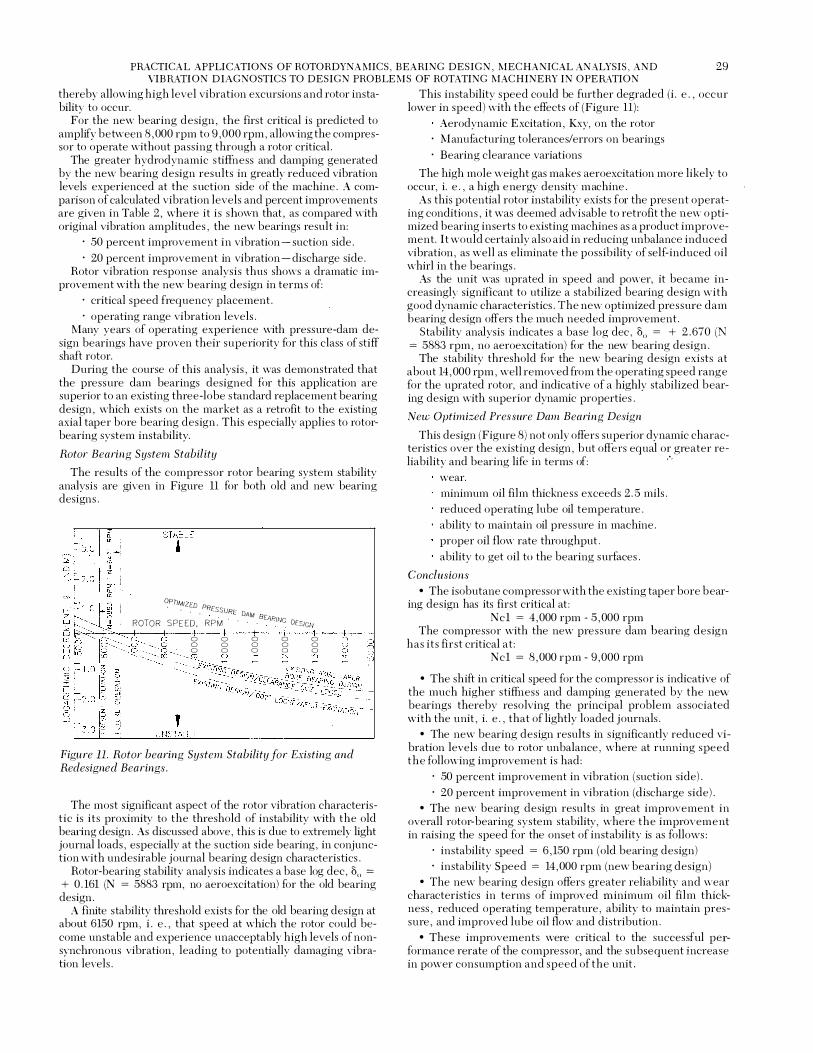
The results of the compre ssor rotor bearing system stability analysis are given in Figure 11 for both old and new bearing designs .
OPTIMIZED . . . . PRESSURE DAM B
ROTOR SPEED, RPM . . · · EARING Of.SiGN 0 0 0
0 0 0 0 0 0
0 0 0 0 0 0
Figure 11. Rotor bearing System Stability for Existing and Redesigned Bearings .
The most significant aspect of the rotor vibration characteristic is its proximity to the threshold of instability with the old beming design. As discussed above, this is due to extremely light journal loads, especially at the suction side bearing, in conjunction with undesirable journal bearing design characteristics .
Rotor-bearing stability analysis indicates a base log dec, 00 :=
+ 0. 161 (N = 5883 rpm, no aeroexcitation) for the old bearing design .
A finite stability threshold exists for the old bearing design at about 6150 rpm, i . e . , that speed at which the rotor could become unstable and experience unacceptably high levels of nonsynchronous vibration, leading to potentially damaging vibration levels .
This instability speed could be further degraded (i . e . , occur lower in speed) with the effects of (Figure 11) :
Aerodynamic Excitation, Kxy, on the rotor · lv1anufacturing tolerances/errors on bearings · Bearing clearance variations
The high mole weight gas makes aeroexcitation more likely to occur, i. e . , a high energy density machine.
As this potential rotor instability exists for the present operating conditions, it was deemed advisable to retrofit the new optimized bearing inserts to existing machines as a product improvement. I t would certainly also aid in reducing unbalance induced vibration, as well as eliminate the possibility of self-induced oil whirl in the bearings .
As the unit was uprated in speed and power, it became increasingly significant to utilize a stabilized bearing design with good dynamic characteristics . The new optimized pressure dam hearing design offers the much needed improvement .
Stability analysis indicates a base log dec, 00 = + 2 . 670 (N = 5883 rpm, no aeroexcitation) for the new bearing design .
The stability threshold for the new bearing design exists at about 14 , 000 rpm, well removed from the operating speed range for the uprated rotor, and indicative of a highly stabilized bearing design with superior dynamic properties .
New Optimized Pressure Dam Bearing Design
This design (Figure 8) not only offers superior dynamic characteristics over the existing design, hut offers equal or greater re-liability and bearing life in terms of: 0 ·
wear. minimum oil film thickness exceeds 2.5 mils . reduced operating lube oil temperature . ability to maintain oil pressure in machine . proper oil flow rate throughput. ability to get oil to the bearing surfaces .
Conclusions • The isobutane compressor with the existing taper bore bear
ing design has its first critical at: Ncl = 4 ,000 rpm- 5 , 000 rpm
The compressor with the new pressure dam hearing design has i ts first critical at :
Ncl = 8 , 000 rpm - 9 ,000 rpm
• The shift in critical speed for the compressor is indicative of the much higher s tiffness and damping generated by the new bearings thereby resolving the principal problem associated with the unit, i . e . , that of lightly loaded journals .
• The new bearing design results in s ignificantly reduced vibration levels due to rotor unbalance, where at running speed the following improvement is had :
· 50 percent improvement in vibration (suction side). · 20 percent improvement in vibration (discharge side) .
• The new bearing design results in great improvement in overall rotor-bearing system stability, where the improvement in raising the speed for the onset of instability is as follows:
· instability speed = 6 , 150 rpm (old bearing design) · instability Speed = 14 , 000 rpm (new bearing design)
• The new bearing design offers greater reliability and wear characteristics in terms of improved minimum oil film thickness, reduced operating temperature, ability to maintain pressure, and improved lube oil flow and distribution .
• These improvements were critical to the successful performance rerate of the compressor, and the subsequent increase in power consumption and speed of the unit.

30 PROCEEDINGS OF THE EIGHTEENTH TURBO MACHINERY SYMPOSIUM
• Following the performanc e rerate and mechanical optimization of the bearing system , the u nit was reinstalled , brought online , and subsequent operation showed high reliability to date with greatly reduced operating vibration levels and no indication of rotor instability.
CASE STUDY 3 Steam Turbine Rebuild and Redesign Study Uncovers the Cause of Past Frequent And Catastrophic Machine Fai lures
Problem Definition
The steam turbine (Figure 12) to be used as a driver for a high pressure barrel hydrogen recycle compressor application experienced in previous service frequent mechanical failures due to excessive machine vibration res ulting in seriously damaged journal bearings , machine internal s , and sometimes fire damage . This past history necessitated the requirement of a thorough engineering analysis prior to rebuild of the existing unit . Upon disassembly and inspection the existing journal bearing inserts , possibly not OEM parts , were found to be questionable relative to their general design and their ability to operate successfully in this (or any) machine . Elements of the problem and its solution included:
· replacement of the existing quasi-pressure-dam bearing inserts with an optimized 5-tilting shoe bearing design (Figure 13) .
· demonstration that the existing bearing design violated numerous accepted standards of hydrodynamic bearing design of this type resulting in severe loss of load capacity .
· loss of hydrodynamic lubrication resulting in boundary lubrication at best and an unstable and unpredictable rotor.
· optimum dynamics and rotor s tability with the redesigned journal bearings mandated for the turbine rebuild .
tBPG. �BPG.
Figure 12. 4,000 HP Five-Stage Steam Turbine Rotor.
Design Critique of Existing Bearing Inserts
The existing highly modified pressure dam type bearing inserts (Figure 13) were not of a sound design for the following reasons :
The pressure s tep , although properly located at Op = 135° (from + X-axis), is heavily undercut to a depth of 0 . 045 to 0 . 050 in , which results in the inability of the dam to generate significant load , which is its principal purpose . A properly designed pressure-dam bearing would use an undercut depth of 3 to 6 times the bearing radial clearance , or 0 . 010 to 0 . 020 in, as shown in Figure 14 , and as reported by Nicholas [2] .
The pressure s tep is machined with a very short axial length , approximately 37 percent of the total bearing land length , and it is once again rendered ineffective . An optimum configuration would use L = 65 to 70 percent, as demonstrated by Nicholas [2] .
cJ;5.000
4AXIAL SLOTS
Figure 13. Existing Highly Modified Pressure-Dam Bearing.
The relief groove which runs along the full arc of the lower bearing half is very undesirable in that it separates the machine's actual bearing smfaces into two 5/8 inch wide strips , effectively nming the machine on "knife-edge s , " resulting in an inadequate hydrodynamic film and the resultant loss of load capacity. (The purpose of a circumferentially grooved lower half bearing is typically to achieve higher unit journal load to enhance s tability. )
Added to this are four milled axial slots in the lower bearing half which divide the two "knife-edges" into three segments each. This could possibly have been an attempt to get more oi l

PRACTICAL APPLICATIONS OF ROTORDYNAMICS, BEARING DESIGN, MECHANICAL ANALYSIS, AND VIBRATION DIAGNOSTICS TO DESIGN PROBLEMS OF ROTATING Iv1ACHINERY IN OPERATION
3 1
3
' '
LOAD CAPACITY-WITH INERTI,A AND TURBULEN:::E
r- ::e: =2. 556
K=cd /c
Figure 14 . Stepped Slider Load Capacity [2] .
to the bearing smfaces , but in reality serves to worsen an already inadequate design , relative to hydrodynamic load capability.
The existing bearing design violates numerous industry accepted standards of hydrodynamic bearing design of this type and the resulting lack of load capacity. The ability to sustain the rotor during normal operation on a hydrodynamic fluid film , avoiding bearing damage and allowing for smooth operation of the rotor, is expected and predicted by analysis (Figure 15) .
3.5
3.0 z
o9 � 2.5�� � w
"'"-ttl L;)o coz 0"' LU -· :j / z oo
....... , 5::>0 � �;I :< "- tfi /� HYDRODYNAMIC LUBRICATION-STABLE OPERATION c;! ---- / j �2F�����6N
TO BEARINGS
"' 1 0 � r ' BOUNDARY LUBRICATION-UNSTABLE OPERATION --!f DAMAGE TO BEARINGS =< UNSAFE REGION
05
2 3 4 5 6 7 8 TURBINE SPEED, RPM X 10-3
9
0%
Figure 15. Minimum Oil Film Thickness of Existing and Retrofit Bearings .
The net result is the lack of hydrodynamic lubrication and the rotor operating with boundary lubrication at best . This leads to premature mechanical damage to bearing surfaces, excessive oil temperature s , high machine vibration, subsequent bearing failure , and possibly worse .
Results of the Rotor Bearing System Dynamics Analysis
Steam Turbine with Existing Pressure Dam Design
Steam Turbine with Optimized Fir;e-Tilting Shoe Retrofit Bearing Design
Undamped Critical Speed Analysis. From the rotor undamped critical speed analysis , the first rigid bearing critical is located above the operating range at Ncr = 11 ,500 cpm .
The second bearing critical (conical mode shape , stiff rotor) i s critically damped and therefore is not a factor in the resonant vibration of this machine for either the old pressure-dam b earings or the new five-tilting shoe bearings .
The steam turbine traverses the firs t critical below normal running speed with the existing bearings . Dynamic response analysis confirms this fact with the damped first critical predicted to occur between Ncl = 3 ,000 rpm to 4 ,000 rpm .
The obvious split between the horizontal and vertical bearing s tiffness characteristics (Table 3) for the existing bearing design reflects the loss ofload capacity ( i . e . , the ability to hold the rotor on a lubricant film without bearing damage) with the old design . For a lightly loaded journal such as this turbine , WILD = 40 PSI , the bearing hydrodynamic characteristics should be symmetrical , as is evidenced by the X and Y characteristics of the new five-tilting pad bearings (Table 3) .
Table 3 . Hydrodynamic Bearing Coefficients - Steam Turbine Redesign .
Startup Suction Pressure
Low (100 psig)
Optimum (400 psig)
High ( 800 psig)
Floating Ring Seal Characteristics @ No=6000 rpm
Cxx Seal Kxy Kyx (Lb-Sec)
Eccentricity (Lb!In) (Lb!In) In
25% - 0- - 0- - 0-
35% 123,000 - 86, 100 265
52% 319,000 - 14 8, 0 00 457
Cyy (Lb-Sec)
In
-0-
376
966
Relative to the immediately preceding discussion , dynamic response analysis confirms the loss of rotor damping and stability with the existing bearings , resulting in high amplification of the first critical . Alternately, dynamic response analysis also demonstJ·ates the turbine with new tilt-pad bearings to be a true s tiff shaft machine, with no amplification of machine criticals in the vicinity of the operating speed range , as the firs t and second criticals are critically damped .
It is significant to note that while the present analysis points out the tremendous improvement in mechanical integrity to be had with the proposed five-pad retrofit bearings , that improvement exceeds what can be shown here analytically. This i s be cause the existing bearings have been conservatively analyze d without the short axial slots which were milled i n the bottom half of the bearings . This unusual feature serves to further degrade the load capacity of these bearings-rendering the bearings incapable of supporting the rotor on a hydrodynamic film. The turbine probably operated on boundary lubrication at best in the past (Figure 15) , thereby creating exces sive bearing wear and damage , and in the event of major upset , would not have had the forgiveness of a rotor operating on a true hydrodynamic film . High lube oil temperatures and high machine vibration should be expected with the existing bearing design .
E specially significant is the fact that the new bearing design results in the steam turbine becoming a true s tiff shaft design , i . e . , one that operates below its first actual critical speed , a very desirable situation relative to machinery vibration and design .
Considerations of light load dynamic response and light load instability are documented in the following. The dynamics and stability analysis will detail the great improvement in mechanical integrity of the s team turbine with the new 5-shoe bearing design .

32 PROCEEDINGS OF THE EIGHTEENTH TURBO MACHINERY SYMPOSIUM
Rotordynamic Response to Residual Unbalance
The results of the rotor unbalance response analysis are given in Figure 16 for both the existing pressure-dam bearing design, and the new five-tilting shoe bearing design , for U = 4W/N ozin unbalance .
0.280
·� 0.240 .
� 0.200 I 1-z ';;;! 0.160
w u 5 0.120 {l_ U) 0 0.080
0.040
0 c:i 0 �
0 0 N
r 6 d 6 6 6 6 n v tl) w r-.. ro
ROTOR SPEED-RPM •10'
0 0 "'
Figure 16 . Rotor Unbalance Response for Existing and Replacement Bearings.
0 0 0
0 �
For the old bearing design , the first critical is predicted to amplify between 3,000 rpm to 4,000 rpm , and it shows its most pronounced peak at the thrust end of the machine .
Vibration levels at the coupling end of the machine are not well-behaved , following a linear ramp-up with speed . This characteristic is indicative of the comb1ned light load/load capacity problem , in which sufficient stiffness and damping are not generated by the existing pressure-dam bearing inserts, thereby allowing high level vibration excursions and rotor instability to occur. This is worsened bv the fact that actual behavior can be further degraded due to the lack of a hydrodynamic film .
For the new bearing design, the first mode is shown to be critically damped , allowing the turbine to operate without passing through a rotor critical .
As shown in Figure 16, the improved hydrodynamic stiffness and damping characteristics generated by the new bearing design result in a greatly improved vibration characteristic experienced by the machine .
Rotor Bearing System Stability
The results of the steam turbine rotor-bearing system stability analysis are given in Figure 17 for both old and new bearing designs .
It is significant to note the relative proximity to the threshold of instability with the old t:s new bearing designs . As discussed previously, any turbine instability here is due to the light journal loads , in conjunction with undesirable journal bearing design characteristic s , driven by any potential de-stabilizing forces .
Rotor/Bearing stability analysis indicates a base log dec , 80 = + 0 . 420 (N = 6000 rpm , no aeroexcitation) for the old bearing design . Stability analysis indicates a base log dec , 80 = + 3 . 520 (N = 6000 rpm, no aeroexcitationl for the new bearing design .
The stability threshold for the new bearing design is far superior to the existing bearing design and indicative of a highly stabilized bearing design with superior dynamic properties .
"" ,.:
� ���===i���±:==E=X=IST=IN;G�B�E;A R�IN�G�OE�S�I G�N�--���� i;l 100,000 1,000,000 0
u AERO-EXCITATION, Q (LB/IN) :; "' '¥ " 3 UNSTABLE
• AT N0 = 6000 RPM OPERATION
Figure 17. Steam Turbine Rotor Stability for Existing and Replacement Bearings .
Conclusions
• The five-tilting shoe replacement bearings for the steam turbine are demonstrated by this engineering study to be the superior choice for this application .
• The existing bearing design violates numerou s accepted standards of hydrodynamic bearing design of this type res ulting in a severe loss of load capacity. This prevents the bearings from sustaining hydrodynamic lubrication and results in the rotor operating 'hith boundary lubrication at bes t .
• Actual operation with the existing bearing inserts i s poss ibly worse than reported here since a lack of hydrodynamic lubrication results in an unstable and unpredictable rotor.
• The steam turbine with the existing pressure-dam bearing design has its highly amplified first critical at :
Ncl = 3,000 rpm to 4,000 rpm The steam turbine with the new five-tilting shoe bearing design is shown to have a critically damped firs t mode, allowing the unit to operate v..ithout passing through a critical speed.
• The new bearing design results in great improvement in overall rotor-bearing system stability, where the improvement in rotor log dec is as follows :
base log dec , 80 = + 0 . 420 (old bearing design) · base log dec , 80 = + 3 . 520 (new bearing design)
CASE STUDY 4 Optimization of the Rotordynamics and Stability for The Compressor of Case Study 3 Th rough a "Modified Soft-Start"
Problem Definition
The eight-stage high pressure barrel hydrogen recycle compressor (Figure 18) whose driver is discussed in Case Study 3 operates on tilting-pad journal bearings and utilizes u nequal pressure floating ring-type oil seals (Figure 19) . This compressor was not a problematic machine in its past service, but it was desh·able upon rebuild and unit packaging with the steam turbine discussed above to optimize its pmformance relative to predicted rotor unbalance response as well as rotor-system stability level . In service pressure levels experienced by the unit are in the neighborhood of 1450 psig at the inlet and 1650 psig at the discharge . The significant influence of high pressure oil seals on rotor system dynamics and stability is well documented in the literature . The purpose of this case history is not to repeat that

PRACTICAL APPLICATIONS OF ROTORDYNAMICS, BEARING DESIGN , MECHANICAL ANALYSIS, AND VIBRATION DIAGNOSTICS TO DESIGN PROBLEMS OF ROTATING MACHINERY IN OPERATION
33
l? O z z � � w z Ill -
Figure 18. Eight-Stage HP Barrell Hydrogen Recycle Compressor Rotor.
Figure 19 . Multiple Breakdown High Pressure Floating-Ring Oil Seal .
theory, but rather to provide an example of the dramatic influence of oil seals on machine dynamics , particularly from an operations personnel perspective . \Vith a basic understanding of how startup procedures influence oil seal forces, centering, and thus hydrodynamic coefficients and the resulting rotordynamics , operations people can easily employ a powerful technique in controlling high level nonsynchronous seal induced vibration. At the same time , unbalance-induced vibration can also be reduced to minimum levels . E lements of the problem and its solution included:
· specification of intermediate level suction pressure startup sequence for the turbine-compressor set in order to optimize unit vibration response-dynamics and stability of the compressor rotor.
· optimization of dynamic characteristics - amplification factor at the critical , frequency placement of the critical , damping capacity at the critical .
· optimization of stability characteristics - base log dec for normal operation, speed at onset of instability, system response to instability mechanisms .
Results of the Rotor Bearing System Dynamics Analysis
Undamped Critical Speed Analysis
As shown in Figure 20 , compressor rotor undamped critical speed map , normal operating speed of 6000 rpm for this unit exhibits excellent separation margins for all potential rotor critical speeds :
N c 1 - first actual rotor critical speed Ncrr first rigid rotor critical speed Nc2 - second actual rotor critical speed N cr2 - second rigid rotor critical speed Nff1 - first free-free critical (third mode)
"b "' "'
,... - \Jndamped - no seal effects
3 rd critical
-------- 2 nd cr it ica l
---1----------- 1 st cr iti c a l St"1f fness
0 ST I FFNESS ( l b/ in)
Figure 20. Recycle Compressor Undamped Critical Speed Map .
The compressor (rebuild configuration) exhibits a first actual rotor critical speed in the vicinity of:
Nc1 = 3000 cpm
from the undamped critical speed map , which does not account for the hydrodynamic interaction of the high pressure seals with the rotor-bearing system (Table 4) . This effect is included in the more detailed confirming analysis , rotordynamic response to residual unbalance .
Table 4 . Hydrodynamic Seal Characteristics - Recycle Compressor Optimization .
(Recommen dt�d ) Op tim ized Optimized
Original 5-Shoc 3-Groove Design Bearin !.� Bearin g Beari n g Paramete r Design De!i if;!;n Design
Kxx i<fo 4700 rpm) 827,000 lhiin 1 , 600,000 lhlin 4 1 0 , 000 l b/in
Kyy ((f� 47CXJ rpm) 1 ,976,000 Jb/in 2 , 800,000 lb/in 2 ,500,000 Jb/in
Cxx (((\ 4700 rpm) 1 , 87R lh-sec!in 3 , 390 lb-sedin 743 lh-sedin
Cyy (6! 4700 rpm ) .5 ,327 lh-sedin 5 , 1 90 lb-sec/in .5692 Jb-sec/in
Kx = 2Kxx 3 . 70 7 . 1 6 1 . 83 Kshufl
Ky = llliYY 8 . 84 1 2 . . 53 1 1 . 1 9 Kshaft
8. , , Base Log Dec + . 235 + . 1 4 6 + . . 36 1
Un stable Frequency 1710 cpm 2 1 30 cpm 1 5.50 cprn
Non�Synchronous A. F. ! .3 . 4 2 1. . 5 8 . 74
1 s t M ode P R F ( l ) !7CXJ c p m 2 1 00 cpm !. 500 cpm
1 s t M ode PRF(2J 2200 cpm 22CXJ cpm 2200 cprn
2nd M ode P R F( l ) 5000 cpm 5700 cpm .3800 cpm
2nd M ode PRF(2) 6250 cpm 6650 cpm 6 1 50 q>m A . F. - I PRF! I J < < J.3. 0 < < 2 1 . 0 < < 8 . 0
A . F. - I P RF(2) 22 .0 22 .0 22 .0
Amp ({t- M idspan 4.5 mils (f� critical 4 . 2.5 mih 0- crit ical 3.6 m i l s @· crit ical
S (it. M i dspan 1 00% 9.5% 80%
Amp ((.! Brg. # l 0 . 30 m i l s � design 0 . 0.5 mils (ci) dt>S ih,'ll 0 . 36 m i l s @ design
A m p (ci, B rg. #2 0 . 30 m ih @· design 0 . 02 m i l s (f� design 0 . 30 mi1s (f� design
S @ Bearing ( l ) 100% 1 6% 120%
S @... Bearing (2) 100% 6% 100%
*A . F. = Ampl ificat ion Factor
As is shown in the unbalance response analysis, no other rotor critical speeds are amplified below or above the compressor ' s normal operating speed range for speeds up to and exceeding 100 percent above the overspeed trip setting .

34 PROCEEDINGS OF THE EIGHTEENTH TURBO MACHINERY SYMPOSIUM
Rotordynamic Response to Residual Unbalance
The results are given in Figure 21 of the rotor unbalance response analysis for allowable unbalance, U = 4 WIN oz-in for the cases of:
· low suction pressure startup , P, = 100 psig . · high suction pressure s tartup , P, = 800 psig . · recommended startup s uction pressure, which is a con
trolled intermediate s uction pressure s tartup , P, = 400 psig, prior to increasing P , .
The seal rings are actually floating bearing elements that , when locked , generate the full hydrodynamic fluid-film reaction . Seal lockup occurs on non pressure balanced seal rings due to high radial friction loading at the seal ring-retainer interface . This lockup force is directly related to the seal pressure as the unit is brought online . The higher the seal pressure on unit startup , the greater the lockup pos ition or eccentricity of the seal , and thus , the greater the destabilizing crosscoupled stiffnes s as well as beneficial direct-coupled damping generated . Optimization then requires a compromise between unbalance response and rotor stability.
0 . 080
0 . 0 7 0
72 0 . 0 6 0 .
� 0 . 0 5 0 I 1-z � 0 . 0 4 0
w u 5 0 . 0 3 0 n_ (/) 0 0 . 020
0 . 010
0 . 0 0 0 0 0 0 2
0 c:i N
ROTOR M I DS PAN --- LOW Ps START - U P - - H I G H Ps START - U P
· REC O M M ENDED P s START - U P
�I �I::; (/) (}_ "' (.) z o �lg_ Cl:O <D w n_ 0
� � q � � 0 0 0 � g � � £ R g g g S
R OTOR SPEED-RPM • 1 0 '
Figure 21 . Rotor Unbalance Response Relative to Suction Pressure at Startup.
For the case of low suction pressure s tartup , the first critical speed is predicted to amplify at 3200 rpm to 3300 rpm , a highly amplified critical with poor damping characteristics .
For the case of high suction pressure s tartup , the first critical is predicted to amplify at 4200 rpm to 4800 rpm , a split critical with two discrete frequency vibration peaks which are welldamped in behavior.
For the case of the recommended s tartup suction pressure, the first critical is predicted to amplify at 3800 rpm to 4100 rpm , essentially a single peak response frequency with a well-damped envelope, and almost critically damped in behavior.
From the preceding discussion , it is clear that the specified suction pressure for s tartup of the turbine-compressor set will optimize the rotordynamics and vibration of the compressor rotor relative to the follo�ing:
Amplification factor at the first critical Frequency placement of the first critical Damping capacity at the first critical Rotor bearing system stability analysis also demonstrates that
not only rotordynamic response, but s tability as well , is op-
timized by the specified starting sequence \\ith respect to compressor suction pressure , P., at startup .
Rotor Bearing System Stability
The results are given in Figure 22 of the compressor rotorbearing system stability analysis for the followin g s tartup conditions :
u w 0 C) 3
Low suction pressure startup , P, = 100 psig High suction pressure s tartup , P, = 800 psig Recommended startup sequence, intermediate P 5 = 400 p sig
AERO-EXCITATION , Q (LB/IN) j • " " o = 6 000 RPM O P ER'l ' O '
UNSTABLE
Figure 22 . Rotor System Stability Relative to Startup Suctio n Pressure.
For N = 6000 rpm and Q = 0 lb/in (no aerodynamic excitation) , the rot01�bearing stability analysis indicates the following values of base log dec, 00(NDIM) , for the respective cases :
Low P, Startup , 00 = + 0 . 240 High P, Startup , 00 = + 0 . 551 Recommended P, S tartup , 00 = + 0 . 995 For N = 6000 rpm and (log dec) = 0, the level of aerodynamic
cross-coupling , Q, required to exceed the threshold of i nstability is respectively :
Low P, startup , Q = 15,500 lb/in High P, startup, Q = 26,000 lb/in Recommended P, s tartup , Q = 30, 000 lb/in From these results , it is clear that the recommended suction
pressure for s tartup of the turbine-compressor set will optimize the rotor-bearing-seal system stability of the comp ressor rotor.
Conclusions
• The recommended starting sequence for the turbinecompressor set relative to compressor suction pres sure will optimize the rotordynamics (vibration and stability) of the com pressor rotor.
• Startup mode will optimize the following rotor vibration characteristics :
amplification factor at the first critical · freqency placement of the first critical · damping capacity at the first critical
• S tartup mode \Vill optimize the follO\ving rotor s tability characteristics :
base log dec, 00 , for normal operation speed at onset of threshold of instability overall system resistance to aeroexcitation

PRACTICAL APPLICATIONS OF ROTORDYNAMICS, BEARING DESIGN, MECHANICAL ANALYSIS, AND VIBRATION DIAGNOSTICS TO DESIGN PROBLEMS OF ROTATING MACHINERY IN OPERATION
35
• The compressor rotor's first critical speed is predicted to amplify at :
Nc1 = 3800 rpm to 4100 rpm essentially a single peak response frequency with a nearly critically damped envelope, for specified startup conditions .
• The compressor rotor's overall system stability indicates a base log dec of
80 = + 0 . 995 for N = (;>000 rpm operation with Q = 0 lb/in (no aerodynamic loading) , a highly stable configuration , for specified stmtup conditions .
CASE STUDY 5
Redesign of Rotor Fits and Retainer Rings for A NO, Module Rotor to Stabilize Rotor Build and Detune Blade Resonance
Problem Def inition
The low pressure expander rotor (Figure 23) ofthis NO, installation dealt the user many and varied problems from the very start of its operation . These included problems with performance, blade resonance, unit vibration during process transients , and most notably rotor upsets during unavoidable and frequent overspeed and overtemperature excursions and tripping offline due to upstream process upsets . These offline trips resulted in the rotor decel down through the critical experiencing high vibration levels . Any attempt to restart after such an excursion resulted in an extremely rough running rotor. Upon disassembly, the rotor was found to have high runouts due to rotor fits and retainer rings allowing the overhung high temperature expander rotor to become skewed and then take a permanent eccentric set on the shaft . Each trip necessitated rotor disassembly in order to relieve the fit runouts and straighten the rotor build . Elements of the problem and its solution included :
· verification that lateral rotordynamic behavior of the unit was acceptable and not the cause of the problem .
· demonstration through finite element analysis that the thermal and centrifugal growths of the rotor retainers were unacceptably high , allowing the rotor to shift and take a permanent set .
· redesign of rotor retainers and fits to stabilize the rotor. · explanation of severe fretting of blade tips of two-piece ex
pander rotor due to loss of fit of old retainers allowing the rotor's fundamental in-phase torsional resonance to drop and become
"z" R ETA I N ER OR I G I NAL F I T • SP I GOT F I T
.003 -.005 T I G H T
SPL I N E �.0 0 1 -.003 T I G HT SHAFT F I T
2 - P I EC E EX PAN DER ROTO R l · P I ECE
COM PR ESSOR ROTO R Figure 23 . 5, .500 HP Low Pressure Stage NO, Module Rotor.
coincident with the blade natural frequency (as measured by testing) . Redesign of the rotor fits raised the rotor torsional critical speed and detuned it from the known blade resonance .
Results of the Rotor Bearing System Dynamics Analysis
The overall rotordynami_c behavior of the NO, module o n accel t o running speed and during normal operation a t design point was found to be completely acceptable relative to machine critical speeds , unbalance response, and stability.
Undamped Critical Speed Analysis
The undamped critical speed map for the NO, rotor indicates excellent operating margins relative to normal operating speed and all machine critical speeds (exceeds API margins ) .
The analysis indicates rigid rotor modes \Vith little bending , good damping, and moderately lightly loaded bearings .
Relative to the observed failure mode of the rotor, shaft end flexibility is not found to be a problem , as is evidenced by dynamic rotor mode shapes in the load (Y) and no-load (X) directions .
The rotor critical speeds are demonstrated not to be sensitive to the potential loss of fit of the expander rotor (and compressor rotor) on the shaft . As such , loss offits adversely affects the rotor mechanically, but does not shift its critical speeds .
Rotordynamic Response to Residual Unbalance
The unbalance response analysis confirms the critical speed analysis in that the normal speed range of the NO, rotor, including up to trip speed, is free of rotor critical speeds for both a rotor with good mechanical integrity and for a rotor with loss of good fits .
Split, well-damped conical rotor modes exis t all the way from 500 rpm to approximately 6500 rpm , mainly due to high bearing stiffness assymetry. These rigid rotor components are welldamped as is evidenced by:
· low amplification factors . · gentle phase shifting on startup .
Third mode response occurs at 14 , 000 rpm to 15 , 000 rpm , well above even the trip level of the rotor, and is itself very well damped for a rotor's third bending critical .
Rotor Bearing System Stability
The rotor bearing system stability analysis of the NO, rotor confirms a highly stable rotor bearing design configuration up through and above 10,000 rpm rotor speed .
The base logarithmic decrement (log dec) of the expander rotor is 80 = + 0 . 810, and the base log dec of the compressor rotor is 80 = + 1 . 280, indicating a highly stable rotordynamics design .
Even for highly elevated levels of aerodynamic excitation .or fluid dynamic jolting, the NO, rotor is not expected to experience rotor-bearing instability at the extreme conditions of overspeed trip , overtemperature trip conditions , and high radial vibration .
Rotor Torsional Critical Speed Analysis
A detailed rotor torsional natural frequency analysis of the NOx module yields the following results (Figure 24) :
· rotor fundamental out-of-phase mode - f = 6058 cpm · rotor fundamental in-phase mode - f = 22 , 162 cpm
These torsional modes do not coincide with any potential rotational excitation frequency.
However, the in-phase mode does coincide almost exactlv with the exducer section blade natural frequency of the tw�piece expander wheel as measured and reported from the NOx module rotor bump test which was performed earlier.

36 PROCEEDINGS OF THE EIGHTEENTH TURBOI'v1ACHINERY SYMPOSIUM
0 ci N n
� 0 OJ N N 0 0 � a . .,.
� "' ::;; Q_ �� o o w O w "' Q_ LO ...J o <( . u o E � 0:: u � � Z o O N Vi � 0:: � 0 ci OJ
0 ci .,.
0 .,. "' OJ -- I I
O ld " Z'' reta i n e r d e s i g n w i t h o r i g i n a l f i t s
-- N e w " r' r et a i n e r d e s i g n w i t h m o d if i e d f i t s
Second m o d e = 2 2 1 6 2 C P M
"0 Q) Q) 0. LO
2 0 . 0 40 . 0 6 0 . 0 8 0 . 0 1 0 0 . 0
R E FE R E N C E S P E E D ( R P fA ) • 1 02
h o s e
1 2 0. 0
Figure 24 . Rotor Torsional Critical Speeds for Existing and Redesigned Retainers .
The in phase rotor mode shape plact s both expander rotor and compressor rotor fit attachments precisely at the nodal points of the two-node mode, the worst case scenario for imparting maximum vibratory torque at resonance , as discussed by Mondy and Mirro [3] , into the expander rotor, which could subsequently excite the exducer blade resonance leading to severe fretting .
The torsional analvsis was based on an assumed los s of fit of the expander rot01: retainers (principally, main rear "Z"retainer) , thereby allowing for additional torsional flexibility of the shaft and thus dropping the in-phase resonance to 22, 162 cpm , coincident with the blade natural frequency.
Reanalvsis of the rotor torsional vibration response without loss of fits
' on the rotor retainers results in the in-phase resonance
shifting upwards in frequency to 28 , 658 cpm , no longer coincident with the exducer blade natural frequency.
Analvsis thus reveals that not only will proper rotor fits provide ac�eptable separation margins between rotational frequencies , rotor torsional natural frequencies and blade flatwise natural frequencies , and improving if not solving the problem of severe blade fretting between the two expander rotor halves , but may also solve the problem of rotor fit loss and the resulting unstable rotor build .
Stress and Deflection Analysis of NO, Expander Rotor, Reta iners , a n d Fits
In the initial work done on the expander rotor, it was concluded that the distress experienced by the NO, module during overspeed trip was caused by the fact that the retainers malfunctioned , i . e . did not provide an adequate fit between the expander wheel and the shaft . Because the coefficient of thermal expansion of the disk is at least 35 percent greater than that of
the retainers or of the shaft , it appeared doubtful that the retainer could maintain good contact with the shaft while res training the wheel rear fit from substantial radial thermal and centrifugal growth .
The sequence of events leading to "kinking" of the shaft is not quite clear, however, i t was calculated that i t takes on ly about 110 lb of lateral load to deflect the shaft end 0 . 004 in , the measured runout at disassembly. A possible explanatio n was that the overspeed and overtemperature excursions were severe enou gh to create sufficient wheel looseness and dynamic unbalance t o cause i t t o experience a high vibration from trip d o w n through the critical . In this event , "cocking" of the retainers apparently occurred with their subsequent tightening during coastdown and cool-down .
Analysis of Rea r '2"- Retainers and Rotor Fits
The thermal coefficient of the A-286 expander rotor i s about 35 percent higher than the 15-5 Ph shaft and 17-4 Ph retainers .
This differential thermal growth results ir). additional radial interference at the rear retainer outside fit of0 . 005-0 . 006in , resulting in a net retainer hoop stress of <T z = 53 , 00 0 psi , without including centrifugal growth .
The actual growth at the bore of the expander rotor at the rear retainer at speed and temperature is : - 0 . 005 in radial due to thermal growth . - 0 . 005 in radial due to centrifugal growth .
Thus , the cumulative potential loss of fit is abou t 0 . 0 10 in radial or 0 . 020 in on the diameter.
The rotor maximum hoop stresses are acceptable with u z
(max) - 42 ,000 ps i . The principal problem with the existing "Z" retainer design
(Figure 23) is inadequate length of fit , resulting in gro s s retainer deflection at the shaft fit and the loss of fit .
With this much thermal and centrifugal hub growth , it would not be feasible to s tabilize the expander rotor with a s imple inside fit , i . e . , bushing the rotor bore and inte1feren ce fitt ing the shaft . This would result in very heavy fits , difficult to assemble , and probably extremely difficult if not impossible to disassemble .
An outside fit design is required with a sufficiently l ong retainer length in order to minimize retainer deflection at the actual retainer to shaft controlling shrink fit , thereby retaining a good fit in operation .
The possible option of an integral rear retainer/seal runner/ thrust collar is not feasible , since it would require m ajor manufacture in the area of designing a new split seal housing and split seal rings , in order to assemble the machine . E ven so, this mav not be feasible due to the \vav this module is assembled .
The only reasonable design alternative, short of expensive (and maybe exotic) redesign , is to counter bore the rear rotor hub deeper axially and extend the retainer ring inside the counterbore of the rotor.
Redesign of Rotor Retainers of Rotor Fits
Details of the rear retainer ring re-design follow (Figure 2.5) :
"T"-design has a maximum possible axial length along the shaft .
the major (controlling) fit (inside counterbore) i s a fairly heavv shrink fit at 0 . 006 in ± 0 . 001 in tight diametral (originally o . oo2 in ± 0 . 001 in tight) .
· the major fit length should be approximately 2 X spigot depth - 1 . 620 in .
· the minor fit to the shaft should be a sliding pilot fit s o i t cannot seize the shaft , 0 . 001 in ± 0 . 001 in tight diametral .
· the center is relieved between fits .

PRACTICAL APPLICATIONS OF ROTORDYNAMICS , BEARING DESIGN, MECHANICAL ANALYSIS, AND VIBRATION DIAGNOSTICS TO DESIGN PROBLEl\IS OF ROTATING MACHINERY IN OPERATION
37
the outside fit (spigot) is 0 . 00 1 in ± 0 . 001 in tight diametral (originally 0 . 004 in ± 0 . 001 in t ight) . This -will gro\v approximately 0 . 010 in tight at normal operating conditions .
· the spigot thickness (retainer to hub) ideally approaches a ratio of l : 1 for optimum compatibility of stress and deflection .
· the material remains 17-4 ph . · any possible added vertical thickness is desirable, with
out modification to the rotor. · the maximum possible s leeve thickness is retained .
The redesigned rear retainer provides a total radial compressive load of approximately 133 , 000 lb on the shaft at steady-state operation of9600 rpm and 600°F (Figure 26) . This is an improvement of a factor of5 . 5 over the existing retainer design . The total force between the wheel and retainer was also increased by almost 30 percent . These improvements provide enough restraint even during a process upset when a sudden temperature increase does momentarily heat the wheel , causing it to grow an additional amount relative to the shaft , and coincident with an overspeed trip .
Figure 25. Redesigned "T- Section" Main Rear Rotor Retainer Ring .
The additional machining (counterbore) at the rear of the expander wheel creates a negligible increase (less than one percent) in effective (vonMises) stress at steady-state operation .
Nose Pilot Retainer Fit Modifications
The nose pilot retainer keeps the existing ''J"-design , but the fits have been modified (Figure 23) .
The inside fit , retainer bore to shaft , is modified to 0 . 000 in ± 0 . 001 in line-to-line diametral (originally 0 . 002 in ± 0 . 001 in tight) .
The outside fit ( spigot) is also modified to 0 . 000 in ± 0 . 001 in line-to-line diametral (originally 0 . 004 in ± 0 . 001 in tight) . This will grow 0 . 002 in to 0 . 003 in tight at speed and temperature .
Unlike the original design which , with its tighter nose pilot fits allowed the rotor, once kinked , to take a permanent set due to front and rear controlling fits , with this differential fit scheme, the rear retainer being the primary controlling fit and the nose retainer being the pilotting slip fit, the rotor will not be able to take a permanent set holding the expander stage nonconcentric . The axial holding force will then locate the nose fit , the recommended prestretch being 0 . 006 in .
Conclusions
• The expander rotor rear retainer is the primary and controlling fit . It has been modified from a "Z" to an "inverted T" design as shown in Figure 25 . The controlling fit , pilot fits , and spigot
_jx y z
Figure 26. Finite Element Deformed Shape of Expander Rotor and Redesigned Rear Retainer at Speed and Temperature .
fits are as indicated . The new design provides sufficient res traint for the rotor even during process upsets .
• The nose pilot retainer keeps the existing "J"-design , but the fits have been modified . . The redesigned differential fit arrangement minimizes the tendency of the rotor to become permanently skewed on the shaft .
• The redesigned rotor retainers and fits will keep the rotor stabilized at speed and temperature and will serve to detune the rotor's in-phase torsional resonance , thereby uncoupling it from the exducer blade fundamental natural frequency at 22 , 162 CPM , and raising it to 28 ,658 cpm . This redesign should alleviate, if not eliminate, the severe blade fretting problem on the two-piece expander rotor.
• For the two-piece expander rotor with interference fit blade halves or "blade tip dampeners , " additional restoration! reclamation recommendations \vere followed including optimization of blade contact remachining angles , utilization of a hightemperature antifretting blade-tip coating , and an improved hub fit design at the bore of the two expander rotor halves , improving rotor mechanical integrity.
• Several secondary recommendations included reorientation of the tilting-pad journal bearings to a load-between-pads configuration , reduction of the operating journal bearing clearances , and elimination of dynamic unbalance from the rotor, in an effort to optimize machine dynamics .
• Redesign of the unit and subsequent restart were successful and operation continued until an unrelated problem forced unit shutdown . An unexpected process upset coincided with shutdown , driving the unit into i ts most violent offline trip recorded to date . Subsequent inspection found the rotor build remained stabilized through this excursion , with no indication ofloss offits during the transient and no residual rotor runouts .
CASE STUDY 6 'lroublesome Nitric Acid Trains Are Successfully Retrofit with Optimized Radial Bearing Inserts
Problem Definition
A recurring problem has been nitric acid expander and compressor rotors (Figure 27) , which have been running for some time and are experiencing a significant degradation in t ime relative to both synchronous and nonsynchronous vibration level s .

38 PROCEEDINGS OF THE EIGHTEENTH TURBO MACHINERY SYMPOSIUM
LO- ST AGE COM P R E SSOR H 1 - STAGE COM P R ESSOR Figu re 27. Nitric Acid Train General Arrangement .
Very high vibration levels have in some instances led to the installation of aftermarket bearing designs - often worsening the problem . Coupled with maintenance-related problems , the overall problem can be compounded and result in great losses due to forced downtime and major plant outages . E lements of the problem and its solution included :
· rotor system dynamics and stability analysis point out the inherent bearing instability which is typical of many of these unit s , which is somewhat insensitive to the specific output of the unit (or its size) .
· stabilized bearing insert design is retrofitted with great success in each case.
· previously installed aftermarket bearing designs were substandard in terms of generally accepted standards of hydrodynamic bearing design and the machinery suffered accordingly high vibration , machine damage, and in some cases , severe damage to the bearings .
· correction of existing problems such as loose bearing housings .
Results of the Rotor Bearing System Dynamics Analysis
The lateral analysis of the subject nitric acid train hot gas expander rotor (Figure 28) indicates well behaved rotordynamic response with operation near 9000 rpm well above the first rotor critical at 3000 rpm (Figure 29) . This resonant peak is a welldamped bearing critical , a bouncing or cylindrical mode, which is of no concern as a synchronous vibration component . The first mode rigid bearing critical is above 13 , 500 rpm allowing the expander to operate as a rigid rotor over its range of operation .
Figure 28. 10, 000 HP Nitric Acid. Hot Gas Expander Rotor.
The high critical speed ratio , operating speed/critical speed = 3 . 0 , is not so fortuitous for the unit relative to nonsynchronous re-excitation of the balance resonance as an instability mechanism . For this class of nitric acid expanders , the mechanism which drives the rotor instability is the class ical light load bearing instability which results from high-speed oil whirl . The original units are highly susceptible to this instability mechanism as they operate on plain sleeve bearings . The existing design of the rotor-bearing system for these expanders has been analyzed for stability. The result is a log dec of8 = - 0 . 25 , a highly unstable configuration . This analysis result is confirmed by recurring operating problems experienced by many users relative to high
O . S O O +-L-----L-'---------L--L�P!:OLA::::I :.::N----=:B=E.��" R.:.:I:.::N:;o::G--l
7 0 . 40 0 0 ";: z I 0 . 3 0 0 1--z w 2 w 5 0 . 2 0 0 Q_ � 0
0 . 1 0 0
0 . 0 0 0
I
0 0 0 0 "'
0 0 ci 0 L[) ,..._ R O T O R S P E E D - R P M • 1 o '
�
I
0 0 0>
Figure 29. Nitric Acid Expander Rotor Unbalance Response .
0 ci
level subsynchronous vibration problems experien ced on their units (Figure 30) .
Operating Experience
For the general machine population in this m achinery class , many units of which have been in operation for more than 10 years , a very high incidence rate exists for this rotor instability problem . Some units showed early symptoms of rotor instability in the form of low level subsynchronous vibratio n , while for others it did not show up in the vibration signature until later i n operation . The instability problem appears and then worsens a s the unit gradually degrades from the as-new condition , since
"' O.. N u w (f) --..... � z .
"' O. N u w (f) '-.... z .
V E R T I CAL B EAR I N G CAP V E L O C ITY
H O R I Z O N T/' L B EAR I N G CAP \UO C I TY
.A. X I A L B EAR I N G Ct1P vE L O C I TY
. 4 0X 1 X
( LO G - L I N EAR SCALE) Figure 30. Expander Tri-Axis Bearing Cap Velocity Vib ration Spectrum.

PRACTICAL APPLICATIONS OF ROTORDYNAMICS, BEARING DESIGN, MECHANICAL ANALYSIS , AND 39 VIBRA.TION DIAGNOSTICS TO DESIGN PROBLEMS OF ROTATING MACHINERY IN OPERATION
this particular machine instability i s very temperamental and depends to a large extent on small variations in operating conditions such as speed, load , ambient conditions , lube oil temperature or pressure, bearing wear, or degradation , etc .
Experience indicates that many bearing retrofits have been made by users who have struggled with this instability problem in past years . Unfortunately, m any of these retrofit bearing designs supplied by aftermarket sources have been found to be substandard in terms of generally accepted standards of hydrodynamic bearing design . As a res ult , these retrofits not only did not provide a bearing design capable of stabilizing the rotor system , but worse, in some instances degraded the system even further through improper design resulting in loss of load capacity or hydrodynamic damping . The end result was continuing vibration problems , bearing damage , and in some cases further machine damage .
Stabilized Bearing Design
An optimized multiple pressure dam bearing insert design (Figure 31) resulted from analysis of the rotor system instability problem . This bearing redesign s tabilizes the rotor, has been show analytically to be the optimum s olution, and has been used in numerous retrofits with 100 percent success in eliminating all subsynchronous vibration as well as improving upon synchronous levels . Instability threshold speeds have been elevated from near operating speed to 100 percent above operating speed . The log dec has been improved from 5 = - 0 . 25 to 5 = + 0 . 30 for the rotor system .
Conclusions • Rotor-system dynamics and stability analysis point out the
inherent bearing instability which is typical of many of these expander units .
• Previously installed aftermarket bearing designs were not capable of stabilizing the rotor system and were substandard in terms of generally accepted standards of hydrodynamic bearing design .
• Correction of existing problems s uch as loose bearing housings was necessary on many of the older units , greatly reducting operating vibration levels .
• A stabilized multidam bearing insert design was retrofit with great success in every case .
CASE STUDY 7 Large Induction Motor/Integral Gear Compressor Experience High Level Torque/Current Pulsations Preventing Unit Startup
Problem Definition
This installation is at an air separation plant near M ilan , Italy, and the problem reached crisis proportions as the unit experienced violent pulsations approximately 35 seconds into the normal startup cycle during multiple attempts to restart . Resulting high level radial vibration readings were observed at the same time approaching 10 mils on some probes and a very loud "thudding" could be heard synchronized with the pulsations . The following machine s ignatures were provided for the transient condition: polyphase current oscillograms , active power, motor speed , and radial vibration spectrums . Elements of the problem and its solution included :
· determination that the problem was more likely electrically induced rather than a flow induced load instability being followed by the motor.
· looking at the starting cycle, it was determined that the rotor circuits were balanced during the acceleration up to the point where the s lip rings were shorted out .
2.25 --+�l f--r-_.J.._---l---�--r---1 ¢4. 124
B
POCKET AREAS
Figure 31 . Redesign Multiple Pressure-Dam Bearing .
· eighteen seconds after the rings are short circuited , current oscillations occur at double slip frequency with a strong harmonic component , indicating one phase of the power s upply is open , the contactor between two rings failed to close, or had an otherwise open circuit .
· recommendation to test the starting circuitry, and not the motor circuit, for the open phase and correct it. This was followed by the motor manufacturer removing the motor from the plant , returning it to the factory, undergoing extensive testing, and a final determination being made that a burned phase existed in the starting circuitry. Correction , reinstallation and subsequent s tartup resulted in successful operation .

40 PROCEEDINGS OF THE EIGHTEENTH TURBO MACHINERY SYMPOSIUM
Initial Analysis Based on Initial Data
For a motor rotor, a rotating magnetic , electrical , or mechanical asymmetry are the cau s e s of many major motor vibration problems . These are caused by a bent shaft, non-circular rotor build , or defective or broken rotor bars . The frequency of vibrations resulting from motor asymmetry are always multiples of electrical or rotational frequency. These components are not present in the site test data (Figure 32) . The motor is possibly responding to a cyclic load being imposed upon it .
It is significant to note that for a wound-rotor motor (slip-ring) induction machine such as this , one does not have an exact means of speed control under varying load conditions (pulses) . That is , a given point on the controller will not necessarily assure a given speed . For a given secondary resistor value, the speed can vary (or pulse) widely if load torque , voltage, or other conditions vary. This would then result in a cyclic current draw and active power generation , Kw.
The data does suggest a possible flow induced pulsation problem giving rise to high vibration and high motor operating transients . This possibility is supported by the 90 cpm low frequency component on the bull gear and second stage rotor (Figures 33, 34) . It was determined , however, upon assessment of the compressor flow condition, that the unit was not being operated in surge . Also , installation of pre s sure transducers in the associated piping of all four compressor s tages resulted in no indications of induced flow pulsations .
Another motor problem poss ibility is with the rotating magnetic pull of the wound rotor, which could possibly give rise to low frequency harmonic excitation . This would typically manifest itself as a torsional oscillation , which in a system such as this integral gear compressor, could easily be translated into a radial and axial vibration . This poss ible excitation of the rotating magnetic field is due to the electrical spring constant , K, and a constant, H , which is a measure of relative system inertias . Estimating the large compressor inertia to be about 4X motor inertia, then
f = 2 . 2(K/H)Y2 = 2 . 2(Y4)112 - 1 . 1 Hz . This is close to the problem frequency indicated .
Although many other possible problem areas exist , the most likely possibility was considered unbalanced rotor circuits . This could result in 2 X slip frequency torque pulsation , modulated by l X s lip frequency. This i s consistent with the observed vibration frequency and its cotresponding beat pulsation frequency :
· Vibration frequency = 90 cpm · Beat frequency = 45 cpm = 0 . 75 Hz = l . 5 percent slip
Since slip is approximately proportional to torque , or load , slip frequency increases when load increase s . This correlates with the motor data for the cases of inlet guide valve (IGV) five degrees opened and ten degrees opened . Thus , the beat frequency could be s lip frequency.
RPM
NORMAL ROTOR
CIRCUIT RESISTOR
CUT-OUT
SUP RINGS AR£ J SHORT CIRCUITED UNDER NORMAL
OPERATING CONDITION
UNSTABLE -
CURRENT AMPLllUDE LOWER THAN UNLOADED AMPS
Figure 32 . 10, 000 HP Induction Motor Starting Cycle Transients .
RANGE : - 1 d BV B : TIM E (R) STAT U S PAU SED
1 0 M I L
X r = 0 , 0 0 0 SEC Xr = 0 .0000 SEC X c � 1 . 809 SEC ' 0 M
2 . 5 I � . A UlAAA I M M . �hJ I� I . I � � A l � ,u � IAIA I A l .JI M I L vn rNNV V Jill I V [ V f V I I Y Vl'l'' 1001 IIHVV ' � VIVV rr n wvv rY' ' /DIV
Xr = 1 00 . 0 mS C CYCLE
!P ER I O D AND Yr = - 7 . 5 1 M I L
OVERALL VIBRATION -.AT 4800\<W AVERAGE LOAD - IGV BOo
- 1 0 START: 0 S E C STO P : 4 S EC
· Figure 33 . Time Base Cyclis Vibration of the Integral Gear Compressor Bull Gear.
An initial check was proposed prior to in depth motor testing in order to determine if the problem was in the external switching circuitry, possibly one of the three-pole contactors \Yas not closing (for example , if the leads burned off} , leaving a motor circuit open . Or possibly a mechanical malfunction occurred in the poles in the switch . This , then could result in the observed rotor electrical unbalance and subsequent twice slip frequency torque pulsation modulated by slip frequency.
Final Analysis Based on Final Data
Examination of the current oscillograms for the full starting cycle (Figure 32) shows that rotor circuits were balanced during the acceleration up to where the slip rings were shorted out (no oscillation of current) .
The observed stepup occurs each time a section of the resistor in the rotor circuit is cut out . In one second , the current drops off as the speed increases . This is as expected .
Approximately 18 seconds after the rings are s hort circuited , the current are seen oscillations at double slip frequency with a strong harmonic component . This fits exactly with the expected pe1formance if one phase is open . the contactor between two rings fails to close , or has an open in its circuit . If the open was in the motor circuit , then this type of pulsation would have occurred throughout the starting cycle .
The severe swing in current, and resulting torque , are due to the high reactance (approaching magnetizing reactance) whe n the flux i n the motor lines u p with this open rotor phase (line t o line) .
The only other possible explanation is that a rotor phase burned open almost simultaneously with the contactor closing that shorts the rings . This would very likely have ended up in a short circuit , which it did not .
A test for the phase balance of the rotor circuits (with stator short circuited) proved the motor stable .
If one contactor pole failed to close , it should be poss ible to check the continuity of the circuit . A contactor pole might fai l once , and then appear all right, but it might fail again , or consecutivelv.
If it is ·a lead burned open, the open circuit is probably at a
brazed or soldered connection It may require a meter reading low circuit resistances to detect the unbalance and locate the spot .
The harmonics of the double slip frequency are caused by the oscillation of the speed and angle . The flux which is trapped by the shorted rotor winding swings in angle causing a higher frequency component of current. The current, which is due to an

PRACTICAL APPLICATIONS OF ROTORDYNAMICS, BEARING DESIGN, MECHANICAL ANALYSIS, AND VIBRATION DIAGNOSTICS TO DESIGN PROBLEMS OF ROTATING MACHINERY IN OPERATION
4 1
3 f.<1 1 L
3 0 0 m i>� I L /D IV
0 M I L
RANGE· - 1 d BV STAT U S · PAUSED X = 19 0 R�M
I I Y= 2 . 5 5 5 M l lrms
X = 9 9 0 R P M Y= 2 . 240 M l lrms
\ n
\ � -J\_ } � � ---./ START: 0 R P H B W : 5 7 . 2 9 1 RPM STO P : 6 0 0 0 R P M
Figure 34 . Vibration Spectrum of the Integral Gear Compressor Bull Gear.
average plus an oscillating component , may actually dip below the no load current , as is shown on the oscillogram .
Problem Resqlution As a result of the analysis , a recommendation was made to test
the starting circuitry, and not the motor circuit , for the open phase and correct it . This was followed by the motor manufachirer removing the motor from the plant , returning it to the factory, undergoing extensive testing , and a final determination being made that a burned phase existed in the starting circuitry. Correction , reinstallation, and subsequent startup resulted in successful operation.
Conclusions • A determination was made that the problem was electrically
induced and not a flow induced load instability. • The startup data indicates that the rotor circuits were ba
lanced during the acceleration up to the point where the slip rings were shorted out.
• After the s lip rings were short circuited, current oscillations occurred at double slip frequency with a strong harmonic component, indicating one phase of the power supply was open .
• A final determination was made that a burned phase existed in the starting circuitry. Correction , reinstallation , and subsequent startup resulted in successful operation .
CASE STUDY 8
Comp ressor Rerate Analysis Demonstrates that Plain Sleece Beari ngs, Not a Tilting Pad "Upgrade , " Are Optimum for Unit Dynamics a nd Stability
Problem Defin ition This propylene compressor (Figure 35) was being peiform
ance rerated and the complete unit rebuild was to include a mechanical upgrade by retrofitting the existing journal bearings with an optimized design . A strong desire was expressed by the client to retrofit with a five-tilting shoe design , considered the obvious best replacement bearing for a machine upgrade . However, the results of this analysis show this large centrifugal compressor to be a classic example of a common occurrence not well
� 1-- r-- � � 1-- 1--
l 11-- -
-,_� y-1-- r-- r- r- 1-- 1--
,L... BRG. ll BR G.
Figure 35. Six-Stage 13, 000 HP Propylene Compressor.
understood in rotating machinery applications - that for many machines the specification of tilting-pad journal bearings is one of the least desirable choices from the standpoint of improved mechanical pe1formance . E lements of the problem and its solution included:
· analytical results clearly demonstrated that even optimum tilting-pad bearings optimized in terms oflengthldiameter ratio , clearance , preload , etc . , generated unacceptably high film stiffness for the compressor rotor, resulting in node points at the bearings . This condition resulted in unacceptable mechanical performance both at normal operating speed and in the critical , which was traversed with a very high amplification factor, AF = 22 .
· an optimized three-axial groove plain insert bearing design is shown to demonstrate superior dynamics and stability characteristics over a wide range of manufacturing tolerances , and i s considered the bearing o f choice fo r this application by analysis and from past practical experience with this class of machinery.
· startup and operation on the redesigned bearings has been highly successful, the rotor operating with very low vibration levels and running smoother than it ever ran before the rework .
Results of the Rotor Bearing System Dynamics Analysis
A detailed rotor system dynamics analysis and bearing design optimization study had been pe1formed in support of a compressor rerate for a six-stage rotor rebuild . The propylene refrigeration unit operates at approximately 13 , 000 hp . 007 4700 rpm .
A comprehensive analysis was made after having developed analytic rotor models which account for shear deformation and include general linearized gyroscopics . Fluid film bearing hydrodynamic characteristics were obtained using the latest finite element analysis techniques to analyze the dynamic lubricant film . Once having established detailed dynamic system models , rotordynamics studies were performed .
The results of the analysis can be summarized as follows . Rotor critical speeds occur at:
Nc1 = 2200 rpm N c2 = 6200 rpm
with the first critical being a highly amplified pure rotor bending mode with an AF, amplification factor = 22 (synchronous) .
Bearing design optimization studies confirmed that an optimized plain insert bearing design is not only the best suited radial bearing for this application , but that a segmented tiltingshoe bearing would be a gross misapplication of that very common bearing "upgrade . " This conclusion results from the fact that optimized five-tilting shoe bearings , at both the critical speed and design speed , generate too much film stiffness resulting in node points at the bearings for this particular application . Thi s , in turn , results in unacceptable dynamic characteristics for the rotor.
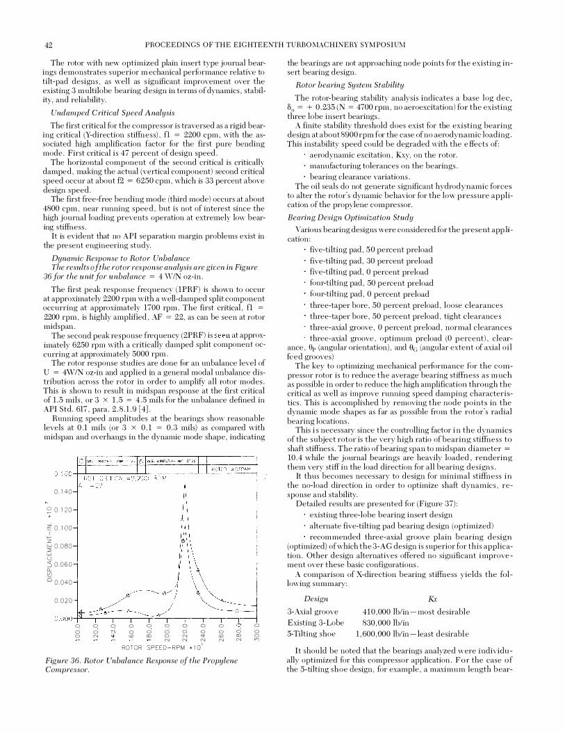
42 PROCEEDINGS OF THE EIGHTEENTH TURBO MACHINERY SYMPOSIUM
The rotor vvith new optimized plain insert type journal bearings demonstrates superior m echanical performance relative to tilt-pad designs , as well as s ignificant improvement over the existing 3 multilobe bearing d esign in terms of dynamics , stability, and reliability.
Undamped Critical Speed Analysis
The first critical for the compressor is traversed as a rigid bearing critical (Y-direction s tiffnes s) , fl = 2200 cpm , with the associated high amplification factor for the first pure bending mode . First critical i s 47 percent of design speed .
The horizontal component of the second critical is critically damped , making the actual (vertical component) second critical speed occur at about f2 = 6250 cpm , which is 33 percent above design speed .
The first free-free bending mode (third mode) occurs at about 4800 cpm , near running spee d , but is not of interest since the high journal loading prevents operation at extremely low bearing s tiffness .
It is evident that no API separation margin problems exist in the present engineering study.
Dynamic Response to Rotor Unbalance The results of the rotor response analysis are given in Figure
36 for the unit for unbalance = 4 WIN oz-in .
The first peak response frequency ( 1PRF) is shown to occur at approximately 2200 rpm with a well-damped split component occurring at approximately 1700 rpm . The first critical , fl = 2200 rpm , is highly amplified , AF = 22, as can be seen at rotor midspan .
The second peak response frequency (2PRF) is seen at approximately 6250 rpm with a critically damped split component occurring at approximately 5000 rpm .
The rotor response studies are done for an unbalance level of U = 4W/N oz-in and applied in a general modal unbalance distribution across the rotor in order to amplify all rotor modes . This is shown to result in midspan response at the first critical of 1 . 5 mils , or 3 X 1 . 5 = 4 . 5 mils for the unbalance defined in API Std . 617 , para . 2 . 8 . 1 . 9 [4] .
Running speed amplitudes at the bearings show reasonable levels at 0 . 1 mils (or 3 X 0 . 1 = 0 .3 mils) as compared with midspan and overhangs in the dynamic mode shape, indicating
'
0 . 1 40
S' 0 . 1 20 *
� 0 . 1 00 I f-z � 0 . 080
w u :5 0 . 0 6 0 CL (f) iS 0 . 0 4 0
0 . 0 2 0
0 ci 0 0 0 N
0 0 0 <!)
0 0 00
0 c: q ci 0 0 0 N '<IN N N ROTOR S P E E D - R P M • 1 o '
0 0 <!) N
0 0 00 N
Figure 36. Rotor Unbalance Response ofthe Propylene Compressor.
0 0 0 n
the bearings are not approaching node points for the existing insert bearing design .
Rotor bearing System Stability
The rotor-bearing stability analysis indicates a base log dec, 50 = + 0 . 235 (N = 4700 rpm , no aeroexcitation) for the existing three lobe insert bearings .
A finite stability threshold does exist for the existing bearing design at about 8900 rpm for the case of no aerodynamic loading . This instability speed could be degraded with the e ffects of:
aerodynamic excitation , Kxy, on the rotor. · manufacturing tolerances on the bearings . · bearing clearance variations .
The oil seals do not generate s ignificant hydrodynamic forces to alter the rotor's dynamic behavior for the low pressure application of the propylene compressor.
Bearing Design Optimization Study
Various bearing designs were considered for the present app lication :
· five-tilting pad , 50 percent preload · five-tilting pad , 30 percent preload
five-tilting pad , 0 percent preload four-tilting pad , 50 percent preload four-tilting pad , 0 percent preload three-taper bore , 50 percent preload , loose clearances three-taper bore , 50 percent preload , tight clearance s three-axial groove , 0 percent preload , normal clearances three-axial groove , optimum preload (0 p ercent) , clear-
ance , \lp (angular orientation) , and tlc (angular extent of axial o i l feed grooves)
The key to optimizing mechanical performance for the compressor rotor is to reduce the average bearing stiffness as m uch as possible in order to reduce the high amplification through the critical as well as improve running speed damping characteristics . This is accomplished by removing the node points in the dynamic mode shapes as far as possible from the rotor's radial bearing locations .
This i s necessary since the controlling factor i n the dynamics of the subject rotor is the very high ratio of bearing s tiffness to shaft stiffnes s . The ratio of bearing span to midspan diameter =
10 . 4 while the journal bearings are heavily loaded , rendering them very stiff in the load direction for all bearing designs .
It thus becomes necessary to design for minimal stiffness in the no-load direction in order to optimize shaft dynamics , response and stability.
Detailed results are presented for (Figure 37) : existing three-lobe bearing insert design alternate five-tilting pad bearing design (optimized) recommended three-axial groove plain bearing design
(optimized) of which the 3-AG design is superior for this application . Other design alternatives offered no significant improve ment over these basic configurations .
A comparison of X-direction bearing stiffness yields the fol lowing summary :
Design
3-Axial groove Existing 3-Lobe S-Tilting shoe
K,; 410 ,000 lb/in - most desirable 830 , 000 lb/in
1 , 600 ,000 lb/in - least desirable
I t should be noted that the bearings analyzed were individually optimized for this compressor application . For the case of the S-tilting shoe design , for example , a maximum length bear-
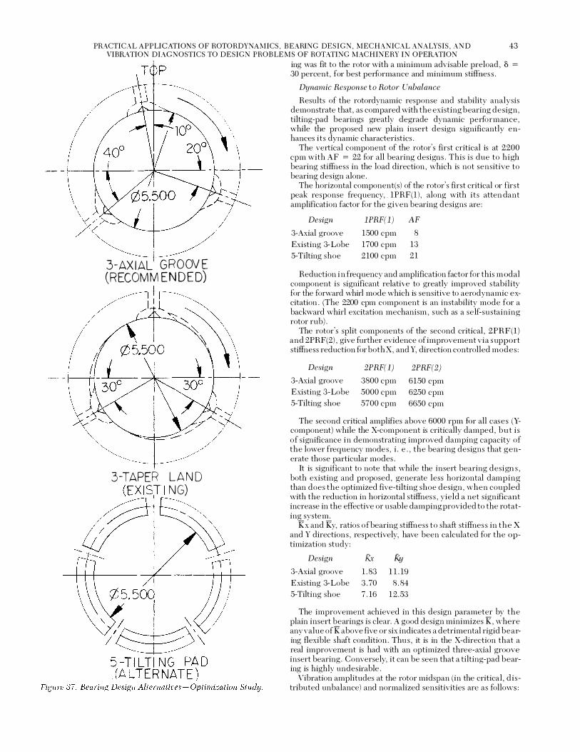
PR.<\CTICAL APPLICATIONS OF ROTORDYNAMICS, BEARING DESIGN , MECHANICAL ANALYSIS, AND VIBR.<\TION DIAGNOSTICS TO DESIGN PROBLEMS OF ROTATING MACHINERY IN OPER.<\TION
43
3-AX I AL G R O OV E (RECOMM ENDED)
3-TAPER LA N D (EX I S� I NG)
ing was fit to the rotor with a minimum advisable preload , 8 =
30 percent, for best performance and minimum stiffues s .
Dynamic Response t o Rotor Unbalance
Results of the rotordynamic response and stability analysis demonstrate that , as compared with the existing bearing design , tilting-pad bearings greatly degrade dynamic performance , while the proposed new plain insert design s ignificantly enhances i t s dynamic characteristics .
The vertical component of the rotor's first critical is at 2200 cpm with AF = 22 for all bearing designs . This is due to high bearing stiffness in the load direction , which is not sensitive to bearing design alone .
The horizontal component(s) of the rotor's first critical or fir s t peak response frequency, . 1PRF(1 ) , along with i t s atten dant amplification factor for the given bearing designs are :
Design lPRF(l) AF
3-Axial groove 1500 cpm 8 Existing 3-Lobe 1700 cpm 13 5-Tilting shoe 2 100 cpm 2 1
Reduction i n frequency and amplification factor for this m odal component is significant relative to greatly improved s tability for the forward whirl mode which is sensitive to aerodynamic excitation . (The 2200 cpm component is an instability mode for a backward whirl excitation mechanism , such as a self-sustaining rotor rub) .
The rotor's split components of the second critical , 2PRF(1) and 2PRF(2) , give further evidence of improvement via s upport stiffness reduction for both X , and Y, direction controlled modes :
Design 2PRF(l) 2PRF(2)
3-Axial groove 3800 cpm 6150 cpm Existing 3-Lobe 5000 cpm 6250 cpm 5-Tilting shoe 5700 cpm 6650 cpm
The second critical amplifies above 6000 rpm for all case s (Ycomponent) while the X-component is critically damped, but i s of significance in demonstrating improved damping capacity of the lower frequency modes , i . e . , the bearing designs that generate those particular modes .
It is significant to note that while the insert bearing design s , both existing and proposed , generate less horizontal damping than does the optimized five-tilting shoe design , when coupled with the reduction in horizontal s tiffnes s , yield a net significant increase in the effective or usable damping provided to the rotating system .
Kx and Ky, ratios of bearing stiffness to shaft stiffnes s in the X and Y directions , respectively, have been calculated for the optimization study :
Design Kx f<y 3-Axial groove 1 . 83 1 1 . 19 Existing 3-Lobe 3 . 70 8 . 84 5-Tilting shoe 7 . 16 1 2 . 53
The improvement achieved in this design parameter by the plain insert bearings is clear. A good design minimizes K , where any value ofK above five or six indicates a detrimental rigid bearing flexible shaft condition . Thu s , it is in the X-direction that a real improvement is had with an optimized three-axial groove insert bearing . Conversely, it can be seen that a tilting-pad bearing is highly undesirable .
Vibration amplitudes at the rotor midspan (in the critical , d i s tributed unbalance) and normalized sensitivities are as follows :
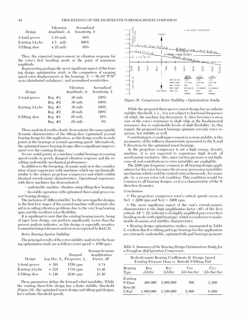
44 PROCEEDINGS OF THE EIGHTEENTH T URBO MACHINERY SYMPOSIU!vl
Vib ration Normalized Design Amplitude, A Sensitivity, S
3-Axial groove 3 . 1 6 mils 80% Existing 3-Lobe 4 . 5 mils 100% 5-Tilting shoe 4 . 25 mils 95%
Thus , the expected improvement in vibration response for the rotor's first bending mode at the point of maximum amplitude .
Representing perhaps the most significant aspect of this bearing design optimization study is the comparison of runnin� speed rotor displacements at the bearings , U = 56, 347 W/N oz-in (distributed unbalance) , and normalized sensitivities :
Vibration Normalized Design Amplitude, A Sensitivity, S
3-Axial groove Brg . # 1 . 36 mils 120% Brg. #2 . 30 mils 100%
Existing 3-Lobe Brg. # 1 . 30 mils 100% Brg . #2 . 30 mils 100%
5-Tilting shoe Brg . # 1 . 05 mils 16% Brg . #2 . 02 mils 6%
These analytical results clearly demonstrate the unacceptable dynamic characteristics of the tilting-shoe (optimized) journal bearing design for this application, as this design results in node points at the bearings at normal operating speed . Alternatively, the optimized insert bearing design offers a significant improvement over the existing design .
Severe nodal points at a machine's radial bearings at running speed results in poorly damped vibration response and the resulting undesirable mechanical pe1formance .
In addition to the foregoing , dynamic analysis is due conside1� ation of past experience with machines which are mechanically similar to the subject propylene compressor and which exhibit identical rotordynamic characteristics . Operational experience with these machines has demonstrated :
· undesirable machine vibration using tilting-shoe bemings . · favorable operation with optimized three-axial groove in
sert bearing design s . The inclusion of"differential fits" for the new impeller designs
in the first four s tages of the rerated machine will certainly also aid in avoiding vibration problems due to the very long bearing span and the resultant rotor flexibility.
It is significant to note that the existing bearing inserts , being of taper bore design , can pe1form significantly worse than the present analysis indicates , as this design is especially sensitive to manufacturing tolerances and errors as reported by Kirk [5 ] .
Rotor Bearing System Stability
The principal results of the rotor s tability analysis for the bearing optimization s tudy are as follows (rotor speed = 4 700 rpm) :
Design
3-Axial groove Existing 3-Lobe 5-Tilting shoe
Log Dec, 30
+ . 361 + .235 + . 146
Damped Frequency, fn
1550 cpm 1710 cpm 2130 cpm
Nonsynchronous Amplification
Factor, AF
8 . 74 13 . 40 21 . 50
These parameters define the forward whirl instability. While the existing three-lobe design has a finite s tability threshold (Figure 38) , the optimized insert design and tilting-pad designs have infinite threshold speeds .
+ . 7 + . 6 + . 5 + . 4
+ . 2 + . 1
- . 1 - . 2 - . 3 - . 4 - . 5 - . 6 - . 7
0 w w
&1 2;: " "' z o ;::: o "' " "' " w a_ 0
<Ill u w 0
'-' s
So = + . 3 6 1
STABLE
I BASE LOG DEC
•
DAMPED FREQ
AMPL FACTOR
�ODE SHAPE
UNSTABLE MODE TYPE
• NO AERO EXCITATION
0 0 0 0 0 0 0 0 "' 0 "' 0 "' "' "' ci
ORIGINAL 5-TP 3-AG BEAAlNGS � BEARINGS
+.2J5 + . 1 46 + . 3 6 1
1 7 1 0 CPI.l 2 1 30 CPM 1 550 CPM
2 1 .5 8 .74
1 !.0 SENDING 1 ST BENDING
TOTAL TOTAL TOTAL
FORWARD fORWARD F'ORWARO
Figure 38. Compressor Rotor Stability - Optimization Study .
While the proposed three-groove insert design has an infinite stability threshold , i . e . , it is not subject to fractional frequency oil whirl , the machine log decrement, 3 , then becomes a m e asure of the rotor's resistance to shaft whip at the fundamental resonance due to undesirable levels of shaft flexibility. I n this regard , the proposed insert bearings optimize not only rotor response , but stability as well .
Contributing to overall improvement in system s tability is the asymmetry of the stiffness characteristic generated in the X and Y directions by the optimized insert bearings .
As the propylene compressor is not a high energy density machine , i t is not expected to experience high levels of aerodynamic excitation . Also , since suction press ure is not high , cone oil seal contributions to rotor instability are negligible .
The 2200 cpm frequency common to all bearing design applications for this rotor becomes the reverse precess ion instability mechanism which could be excited subsynchronously, for example , by a severe rotor rub condition . This condition would b e common t o all bem·ing designs , a s it i s a characteristic o f the Ydirection dynamics .
Conclusions • The propylene compressor rotor's critical speeds occur a t
Ncl = 2200 rpm and Nc2 = 6200 cpm . • The most s ignificant aspect of the unit's rotordynamics
characteristics is the high amplification factor (AF) of the fir s t critical , AF = 22, indicative of a highly amplified pure rotor fir s t bending mode (with rigid bearings) , which is conducive t o undesirable dynamics and stability characteristics .
• Bearing design optimization studies , summarized in Tabl e 5 , confirm that five-tilting pad type bearings for this application are extremely undesirable , optimized tilt-pad bearings generat-
Table 5. Summary of the Bearing Design Optimizati{ln Study for a Propylene Refrigeration Compressor.
Hydrodynamic Bearing Coefficients @ Design Speed Existing Pressure Dam vs . Retrofit 5-Tilting Pad
Bem·ing Kxx Kyy Cxx Cvv Type (Lblln) (Lb/In) (Lb-Sec/ln) (Lb-s�·
c!In)
Existing P-Dam 400 ,000 2 , 000,000 580 3 , 300 Retrofit 5-Pad 1 , 000,000 1 , 100 ,000 2 , 800 6 , 600

PRACTICAL APPLICATIONS OF ROTORDYNAMICS, BEARING DESIGN, MECHANICAL ANALYSIS, AND 45 VIBRATION DIAGNOSTICS TO DESIGN P ROBLEMS OF ROTATING MACHINERY IN OPERATION
ing too much stiffuess for the compressor rotor, resulting in un- The documented case histories deal with a variety of machin-acceptable mechanical performance both at normal operating ery design problems including gear design , gearbox bearing de-speed and in the critical . sign , gas compressor bearing redesign as part of a performance
o An optimized three-axial groove insert bearing design is upgrade, steam turbine bearing redesign to obtain unit reliabil-shown to demonstrate superior dynamics and stability cnarac- ity, an operations approach to rotordynamics optimization of a teristics over a wide range of m anufacturing tolerances . The high pressure barrel compres sor, rotor assembly redesign to proposed insert bearing design i s considered the bearing of s tabilize the rotor build of a high temperature NOx module , nit-choice for this particular applicat io n , not only by analysis , but ric acid expander bearing redesign for system stability and relia-from experience . bility, large induction motor starting circuitry transients and
o Startup and operation on the redesigned bearings has been problem resolution , and refrigeration compressor bearing de-
highly successful , the rotor operating with very low vibration sign optimization study demonstrates the s ignificant disadvan-
levels , and running smoother than i t ever ran before the rework . tages of five tilting pad bearings for that application .
SUM MARY AND CONCLUSIONS The machinery case histories detailed herein illustrate some
of the variety and sublety of design problems encountered in existing rotating machinery and their engineering resolutions , including upgrade and redesign . A significant purpose of the technical information presented here is to help in avoiding improper diagnosis and treatment of m achinery design problems by treating them as recurring maintenance problems . This common misdiagnosis continues to result in unnecessary maintenance expense and very costly downtime .
Examples of the common requirem ent for proper redesign are demonstrated in the areas of:
· machinery built before the development of today' s powerful design tools in the areas of rotordynamics and bearing design .
· marginal machines that operate satisfactorily until they are rerated , . their greater output resulting in the need for mechanical upgrade .
· poorly designed or improperly designed aftermarket or OEM parts that have been retrofitted to existing machines .
· units that can be improved via design optimization in order to enhance future operational reliability.
· analytical design studies that uncover potential future operational machine problems .
REFERENCES 1 . Lifson, A . , S immons , H . R . , and Smalley, A . J . , "Vibration
Limits for Rotating M achinery," M echanical E ngineering , pp . 60-63 (June 1987) .
2 . Nicholas , J . C . , "Pressure Dam Bearing Design for Optimum Turbomachinery Stability, " Hydrocarbon Proces sing, pp . 91-97 (April 1983) .
3 . M ondy, R . E . , and Mirro , J . , "The Calculation and Verification of Torsional Natural Frequencies for Turbomachinery E quipment Strings , " Proceedings of the Eleventh Turbomachinery Symposium, Turbomachinery Laboratory, Department of M echanical Engineering, Texas A&M University, College S tation , Texas , pp . 151- 156 ( 1982) .
4 . American Petroleum Institute , "Centrifugal Compressors for General Refinery S ervices , " API S tandard 617 , 5th E dition , ( 1988) .
5 . Kirk , R . G . , "The Influence of Manufacturing Tolerances on M ulti-Lobe Bearing Performance in Turbomachinery, " Topics in Fluid Film Bearing and Rotor Bearing System Design and Optimization , an AS M E publication , pp . 108- 129 (April 1978) .

46 PROCEEDINGS OF THE EIGHTEENTH TURBO MACHINERY SYMPOSIUM