)joebxj1vcmjtijoh$psqpsbujpo …downloads.hindawi.com/journals/stni/2015/150373.pdfis introduced...
TRANSCRIPT

Research ArticleAn Innovative Passive Residual Heat Removal System ofan Open-Pool Type Research Reactor with Pump Flywheel andGravity Core Cooling Tank
Kwon-Yeong Lee1 and Hyun-Gi Yoon2
1Handong Global University, 558 Handong-Ro, Heunghae-eup, Buk-gu, Pohang, Gyeongbuk 791-708, Republic of Korea2Korea Atomic Energy Research Institute, Daedeok-daero 989-111, Yuseong-gu, Daejeon 305-353, Republic of Korea
Correspondence should be addressed to Kwon-Yeong Lee; [email protected]
Received 6 July 2015; Accepted 5 August 2015
Academic Editor: Eugenijus Uspuras
Copyright © 2015 K.-Y. Lee and H.-G. Yoon. This is an open access article distributed under the Creative Commons AttributionLicense, which permits unrestricted use, distribution, and reproduction in any medium, provided the original work is properlycited.
In an open-pool type research reactor, the primary cooling system can be designed to have a downward flow inside the core duringnormal operation because of the plate type fuel geometry. There is a flow inversion inside the core from the downward flow by theinertia force of the primary coolant to the upward flow by the natural circulation when the pump is turned off. To delay the flowinversion time, an innovative passive system with pump flywheel and GCCT is developed to remove the residual heat. Before theprimary cooling pump starts up, the water level of the GCCT is the same as that of the reactor pool. During the primary coolingpump operation, the water in the GCCT is moved into the reactor pool because of the pump suction head. After the pump stops,the potential head generates a downward flow inside the core by moving the water from the reactor pool to the GCCT and removesthe residual heat. When the water levels of the two pools are the same again, the core flow has an inversion of the flow direction,and natural circulation is developed through the flap valves.
1. Introduction
Research reactors are generally divided into a tank-in-pooltype and an open-pool type [1]. An open-pool type researchreactor has a benefit from the viewpoint of reactor usagesuch as isotope production because the top of the core isopened. In an open-pool type research reactor, the decay heatof the core is transferred into the reactor pool by a naturalcirculation through the flap valves after the Primary CoolingPump (PCP) is turned off. That is, the flap valves installedon the pipe of the Primary Cooling System (PCS) inside thereactor pool are designed to be passively opened, when theflow rate of the PCS is reduced below the design limit. If thecore flow is in an upward direction during PCP operation, thetransition from a forced convection to a natural convectionwill be natural, and concerns regarding the core damage willbe very small. However, there is a recent trend to use a platetype fuel, and a core downward flow is considered because itis benefit to install a plate type fuel in the core. In this case,a flow inversion from a downward to upward flow in the core
is generated after the PCP is turned off. If this phenomenonis introduced within a high heat flux region of residual heat,the fuel fails instantly due to a zero flow. Therefore, the coredownward flow should be sufficiently maintained until theresidual heat is in a low heat flux region.
In a small power research reactor, inertia generated by aflywheel of the PCP can maintain a downward flow shortlyand resolve the problem of a flow inversion. However, a highpower research reactor of more than 10MW should have anadditionalmethod to generate a longer downward flowuntil alow heat flux is reached. Usually, other research reactors haveselected an active residual heat removal system as a safetyclass. In this case, it is difficult to design and operate an activesystem pump because its operating point varies according tothe operation conditions of the PCP. In addition, the systemshould have two separate trains considering the redundancyand diversity and safety class UPS (Uninterruptible PowerSupply) or EDG (Emergency Diesel Generator) consideringa loss of electric power accident.
Hindawi Publishing CorporationScience and Technology of Nuclear InstallationsVolume 2015, Article ID 150373, 7 pageshttp://dx.doi.org/10.1155/2015/150373
2 Science and Technology of Nuclear Installations
In addition, the consumption of radioactive isotopeshas recently increased for cancer diagnosis. However, iso-tope production research reactors around in the world aredeteriorating and have low efficiency. Therefore, there areseveral plans to construct new research reactors for isotopeproduction including the KJRR (KIJANG Research Reactor)of South Korea. A workplace to replace fuels and isotopetargets is at the top of the reactor pool, and replacementworksare difficult and take several days because of the heat waves bynatural convection in the decay heat removal process. Thus,it is necessary to maintain a downward flow in the core witha low flow rate for the decay heat and heat wave removal.
2. System Description
2.1. Pool-Type Reactor Subgroups. DOE category III (pool-type) reactors are divided into two broad subgroups based onthe maximum steady-state thermal power of the reactor [2].The power ranges that define the subgroups are as follows:
(A) Power ≤ 1MW,(B) 1MW < Power ≤ 10MW.
The first subgroup does not require active systems for reactorheat removal. Natural circulation is sufficient to cool the core.The second subgroup requires forced circulation to removehigh reactor power (>1MW). Additionally, a third subgroupoperating at greater than 10MWthermal power is considered.
2.2. Pump Flywheel. A pump coastdown means a pumpoperation with the angular momentum of the shaft, impeller,and flywheel if a loss of off-site power occurs. At this time,the flow rate decreases slowly by the effect of the moment ofinertia, and therefore, core cooling is continued smoothly.
Here, a modified hydraulic efficiency model for thePCP coastdown of the HANARO (High Flux AdvancedNeutron Application ReactOr) was developed and evaluatedwith the field data [3]. The HANARO is a multipurposeresearch reactor in South Korea with the much expandedcapability of neutron beam research, nuclear fuel andmaterialirradiation, radioisotope production, neutron transmutationdoping, neutron radiography, neutron activation analysis,and other basic researches. It has an open tank-in-pool foreasy access and light water coolant. The moderator uses acombination of light water and heavy water, and the designthermal power is 30MW. The type of the PCP of HANAROis a typical centrifugal pumpwith a specific speed of 315 [rpm,m3/min, m] and specific diameter of 0.31 [m, m3/min, m]. Inthis pump, a flywheel is connected with the rotating shaft andlocated at the back of the electric motor and its moment ofinertia, 𝐼, is 156.9 kg⋅m2. The moment of inertia of the shaftand impeller was not considered in this simulation becauseits value was relatively small compared to that of the flywheel.
When a loss of off-site power occurs, the PCP starts tooperate with the power of the flywheel. At this time, theflywheel has the angular momentum directly proportionalto its moments of inertia and angular velocity of the pumpimpeller. The flywheel supplies the break horse power to thepump through the connected shaft.The initial supplied power
Affinity laws of the pump
𝛼i =Pd
𝜂hI𝜔d
=mdghd𝜂hI𝜔d
𝜔i = 𝜔d + 𝛼iΔt
Pi = Pd( 𝜔i
𝜔d
)3
= dghd( 𝜔i
𝜔d
)3
𝛼i+1 =Pi
𝜂hI𝜔i
𝜔i+1 = 𝜔i + 𝛼i+1Δt
Pi+1 = Pd
Flow rate: Q ∝ ND3
Head: gH ∝ N2D2
Power: P ∝ 𝜌N3D5
N = rotational speedD = impeller diameter
(𝜔i+1
𝜔d
)3
.
m.
Figure 1: Calculation diagram of the coastdown.
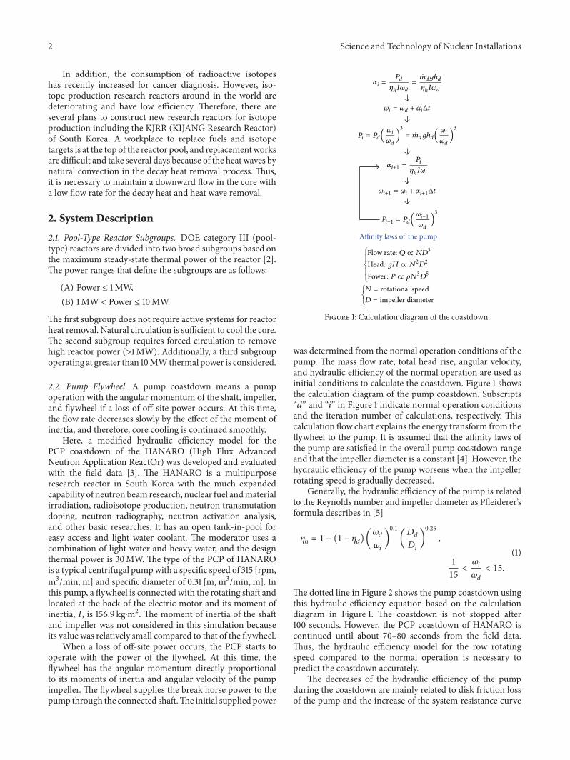
was determined from the normal operation conditions of thepump. The mass flow rate, total head rise, angular velocity,and hydraulic efficiency of the normal operation are used asinitial conditions to calculate the coastdown. Figure 1 showsthe calculation diagram of the pump coastdown. Subscripts“𝑑” and “𝑖” in Figure 1 indicate normal operation conditionsand the iteration number of calculations, respectively. Thiscalculation flow chart explains the energy transform from theflywheel to the pump. It is assumed that the affinity laws ofthe pump are satisfied in the overall pump coastdown rangeand that the impeller diameter is a constant [4]. However, thehydraulic efficiency of the pump worsens when the impellerrotating speed is gradually decreased.
Generally, the hydraulic efficiency of the pump is relatedto the Reynolds number and impeller diameter as Pfleiderer’sformula describes in [5]
𝜂ℎ= 1 − (1 − 𝜂
𝑑) (
𝜔𝑑
𝜔𝑖
)
0.1
(𝐷𝑑
𝐷𝑖
)
0.25
,
1
15<𝜔𝑖
𝜔𝑑
< 15.
(1)
The dotted line in Figure 2 shows the pump coastdown usingthis hydraulic efficiency equation based on the calculationdiagram in Figure 1. The coastdown is not stopped after100 seconds. However, the PCP coastdown of HANARO iscontinued until about 70–80 seconds from the field data.Thus, the hydraulic efficiency model for the row rotatingspeed compared to the normal operation is necessary topredict the coastdown accurately.
The decreases of the hydraulic efficiency of the pumpduring the coastdown are mainly related to disk friction lossof the pump and the increase of the system resistance curve

Science and Technology of Nuclear Installations 3M
ass fl
ow ra
te (k
g/se
c)
800
700
600
500
400
300
200
100
0
Time (sec)
Real caseIdeal case
706050403020100
Figure 2: Coastdown of the pump with time (HANARO).
while the rotating speed is deceased [5–8]. The proportionof the disk friction loss to the pump head rise increasesrapidly when the impeller rotating speed decreases as shownin Figure 3. In addition, the slope of the system resistancecurve is steeper in the low flow rate region because of theincrease of the friction loss. It shifts the operating pointof the pump from the rated region to the low flow rateregion, as described in Figure 4. These two factors decreasethe hydraulic efficiency of the pump. In this research, themodified hydraulic efficiency model is suggested through (2)and (3) based on Pfleiderer’s model. Consider
𝜂ℎ= 1 − (1 − 𝜂
𝑑) (
𝜔𝑑
𝜔𝑖
)
0.1
(𝐷𝑑
𝐷𝑖
)
0.25
when 0.2 <𝜔𝑖
𝜔𝑑
< 1,
(2)
𝜂ℎ= 1 − (1 − 𝜂
𝑑) (
𝜔𝑑
𝜔𝑖
)
0.1
(𝐷𝑑
𝐷𝑖
)
0.25
⋅ exp(−25(0.2 −𝜔𝑖
𝜔𝑑
)) when 0 <𝜔𝑖
𝜔𝑑
< 0.2.
(3)
In (3), a model constant of −25 is selected based on thecoastdown time ofHANARO.The solid line in Figure 2 showsthe pump coastdown using this modified hydraulic efficiencyequation. The pump stopped at about 70 seconds.
2.3. Gravity Core Cooling Tank. A Passive Residual HeatRemoval System (PRHRS) for an open-pool type researchreactor was developed using a Gravity Core Cooling Tank(GCCT), as shown in Figure 5 [9, 10]. The GCCT beside thereactor pool is a small tank opening into the air with atmo-spheric pressure. A Residual Heat Removal Pipe (RHRP)is connected to a lower plenum of the Reactor StructureAssembly (RSA) and bottom of the GCCT. Thus, coolingwater passing the core can flow to the GCCT through theRHRP to remove core decay heat.
hdi
sk fr
ic. l
oss/h
0.5
0.4
0.3
0.2
0.1
𝜔i/𝜔d
0.60.50.40.30.20.10
Figure 3: Proportion of the disk friction loss to the pump head raisewith the impeller rotating speed.
Q
HSystem curve
Pump curves
Decrease of N
Figure 4: Change of the system resistance curve with the decreaseof the flow rate.
Additionally, a Pool Water Cooling and PurificationSystem (PWCPS) was designed to improve the safety andusability of the research reactor, as shown in Figure 5. APWCPS consists of a pump, a flow control valve, a heatexchanger, a filter, an ion exchanger, and related pipes. ADecay Wall (DW) is installed to separate a discharge areafrom the RHRP and a suction area of the PWCPS pumpbecause the cooling water passing the core has a very highradiation level. Namely, cooling water discharged from theRHRP stays for a sufficiently long time inside the GCCTbefore entering the PWCPS to decay out N-16, which has ahigh radiation level but short half-life. As a result, the coolingwater inside the PWCPS has a low radiation level, and thedesign of the PWCPS is easy and cheap.
Here, the reactor pool, GCCT, and RHRP shall bedesigned as the safety class, but the PWCPS will be anonsafety class because it is not directly related to reactorsafety.
2.3.1. PCS Operation Stage. Figure 5 shows the reactor off,PCP off, and PWCPS pump off states of an open-pool typeresearch reactor. The reactor pool and GCCT have the same

4 Science and Technology of Nuclear Installations
GCCTPCS
Reactor pool
PCS
P
HX
F
IX
Reactor
PWCPS
Pump off
PCP off
Reactor off
GCCT: gravity core cooling tankRHRP: residual heat removal pipeDW: decay wallPWCPS: pool water cooling and purification systemP: pumpCV: control valveHX: heat exchangerF: filterIX: ion exchanger
CV
DW RHRP
Figure 5: Schematic diagram of PRHRS using GCCT.
pool water levels because cooling water can move freelythrough the RHRP between the two pools.
After the PCP is turned on, the water level of the GCCTgradually decreases because some water moves from theGCCT to the reactor pool through the RHRP. An increase ofthe reactor poolwater level is small because the surface area ofthe reactor pool ismuch larger than that of GCCT. Finally, thetwo pools have a water level difference, as shown in Figure 6,and the flow of cooling water through the RHRP is stopped.Here, the hydrostatic head by the water level difference is thesame as the pressure drop through the core.
2.3.2. Normal Power Operation Stage. PWCPS is turned onafter the PCS, reactor pool, and GCCT are in stable operationconditions. Cooling water flows in the PWCPS from theGCCT and is discharged into the reactor pool after passingthe pump, heat exchanger, filter, and ion exchanger of thePWCPS. Some reactor poolwater is suctioned into the reactorthrough the top opening of the RSA, mixed with PCS water,and passed the core. Some of the heated cooling water atthe lower plenum of the RSA moves into the GCCT throughRHRP. After PWCPS is stable with the balanced mass flowrates, the reactor will start a power operation. A flow diagramfor normal power operation conditions is shown in Figure 7.
When PCS water is discharged into the RSA, some PCSwater will be released into the reactor pool through the top
GCCTPCS
Reactor pool
PCS
P
H/E
F
IX
Reactor
PWCPS
Reactor off
PCP on
Pump off
CV
DWRHRP
Figure 6: PCS operation.
GCCTPCS
Reactor pool
PCS
P
H/E
F
IX
Reactor
PWCPSPump on
Reactor on
PCP on
CV
DWRHRP
Figure 7: Reactor operation.
opening of the RSA owing to collisions between the flows andstructures. It will generate some flow in the upper section ofthe reactor pool above the reactor, and this flowwill make theradiation material move on the surface of the reactor pool. Inthis case, the reactor operation will be impossible because ofa high pool top surface radiation limit. However, the suctionflow of the reactor pool water through the top opening of theRSA blocks the released PCS flow, and the pool top surfaceradiation level is low. In addition, an extra purification systemfor a PCS is not required because the purified water from aPWCPS is mixed with PCS water.
2.3.3. Normal Shutdown Stage. Figure 8 shows the pool waterlevel and flow when nuclear fuel or targets for isotope
Science and Technology of Nuclear Installations 5
GCCTPCS
PCP off
Reactor off
Pump on
Reactor pool
PCS
P
H/E
F
IX
Reactor
PWCPS
CV
DWRHRP
Figure 8: Reactor normal shutdown.
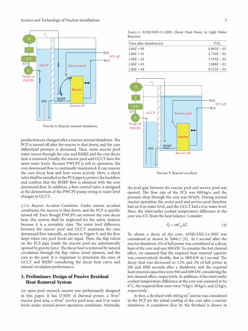
production are changed after a reactor normal shutdown.ThePCP is turned off after the reactor is shut down, and the coredifferential pressure is decreased. Then, some reactor poolwater moves through the core and RHRP, and the core decayheat is removed. Finally, the reactor pool and GCCT have thesame water levels. Because PWCPS is still in operation, thecore downward flow is continually maintained. It can removethe core decay heat and heat waves actively. Here, a checkvalve shall be installed in the PCS pipe to protect the backflowand confirm that the RHRP flow is identical with the coredownward flow. In addition, a flow control valve is designedat the downstream of the PWCPS pump owing to water levelchanges in GCCT.
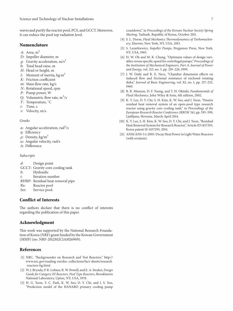
2.3.4. Reactor Accident Condition. Under reactor accidentconditions, the reactor is shut down, and the PCP is quicklyturned off. Even though PWCPS can remove the core decayheat, this system shall be neglected for the safety analysisbecause it is a nonsafety class. The water level differencebetween the reactor pool and GCCT maintains the coredownward flow naturally, as shown in Figure 9, and the flowstops when two pool levels are equal. Then, the flap valveson the PCS pipe inside the reactor pool are automaticallyopened by gravity force.The decay heat is removed by naturalcirculation through the flap valves, lower plenum, and thecore to the pool. It is important to determine the sizes ofGCCT and RHRP considering the decay heat curve andnatural circulation performance.
3. Preliminary Design of Passive ResidualHeat Removal System
An open-pool research reactor was preliminarily designedin this paper. It has 15MW of thermal power, a 30m2reactor pool area, a 40m2 service pool area, and 11m waterlevels under normal power operation conditions. Normally,
Table 1: ANSI/ANS-5.1-2005, Decay Heat Power in Light WaterReactors.
Time after shutdown(s) 𝑃/𝑃0
1.00𝐸 + 00 6.065𝐸 − 02
1.00𝐸 + 01 4.730𝐸 − 02
1.00𝐸 + 02 3.193𝐸 − 02
1.00𝐸 + 03 1.980𝐸 − 02
1.00𝐸 + 04 9.721𝐸 − 03
GCCTPCS
Reactor pool
PCSPCP off
Reactor off
Pump off
P
H/E
F
IX
Reactor
PWCPS
CV
DWRHRP
Figure 9: Reactor accident.
the pool gate between the reactor pool and service pool wasopened. The flow rate of the PCS was 600 kg/s, and thepressure drop through the core was 110 kPa. During normalreactor operation, the rector pool and service pool thereforehad an 11m water level, and the GCCT had a 0m water level.Here, the inlet/outlet coolant temperature difference at thecore was 6∘C from the heat balance. Consider
𝑄 = ��𝐶𝑝Δ𝑇. (4)
To obtain a decay of the core, ANSI/ANS-5.1-2005 wasconsidered as shown in Table 1 [11]. At 1 second after thereactor shutdown, 6% of full power was considered as a decayheat of the core and was 900 kW. To consider the hot channeleffect, we assumed that the required heat removal capacitywas conservatively double, that is, 1800 kW at 1 second. Thedecay heat was decreased to 3.2% and 2% of full power at100 and 1000 seconds after a shutdown, and the requiredheat removal capacities were 960 and 600 kWconsidering thehot channel effect, respectively. In addition, if the inlet/outletcoolant temperature difference at the core was assumed to be6∘C, the required flow rates were 71 kg/s, 38 kg/s, and 22 kg/s,respectively.
At first, a flywheel with 160 kg⋅m2 inertia was consideredin the PCP for the initial cooling of the core after a reactorshutdown. A coastdown flow by the flywheel is shown in

6 Science and Technology of Nuclear InstallationsM
ass fl
ow ra
te (k
g/se
c)
Elapsed time (sec)200180160140120100806040200
0
100
200
300
400
500
600
700
Figure 10: Coastdown of the pump with time (designed).
Figure 10. It was sufficient to maintain the downward flow toremove the core decay heat until approximately 130 seconds.
Next, a GCCT with a 5m2 pool area and a 5-inch RHRPwas considered.The friction coefficient from the reactor poolto the GCCT was 8 considering the pressure drop throughthe core and RHRP. The velocity at the RHRP was calculatedfrom the Bernoulli equation:
V = √2𝑔 (𝐻
1− 𝐻2)
1 + 𝐾12
. (5)
The flow rate through the RHRP was calculated as follows:�� = 𝜌𝐴RHRPV. (6)
The reactor pool water level gradually decreased and theGCCT water level increased. The flow disappeared whenthe two water levels were the same. To consider these levelchanges, the following simple equations are used:
𝐻1= 𝐻Rx − ∫
�� (𝑡)
𝜌𝐴Rx+Ser𝑑𝑡,
𝐻2= 𝐻GCCT + ∫
�� (𝑡)
𝜌𝐴GCCT𝑑𝑡.
(7)
Figures 11 and 12 show the flow rate from the reactor poolto the GCCT along with their water levels. The flow rate wasdecreased linearly but was higher than the required flow ratesuntil 1000 seconds. The flow stopped at 1624 seconds, andthe final water levels were identically 10.3m. Here, we shouldregard the flow through the RHRP to start from a zero flowrate. Therefore, the PCS flow inertia and flywheel should beused to cool the core immediately after a reactor shutdown.The GCCT may be capable of applying an intermediatecooling method.
Regarding the characteristics of subgroup (A) describedin Section 2.1, we can think that a natural circulation flowcan be removed at 300 kW or less of decay heat after 1000second, and the flow reversal from downward to upward atthe core may be permitted. For long-term cooling, the flapvalve will be opened at around 1000 seconds after a shutdownto generate natural circulation. Actually, a study on naturalcirculation is another research topic.
Mas
s flow
rate
(kg/
sec)
80
70
60
50
40
30
20
10
0
Time (sec)
Calculated flow rateRequired flow rate
180016001400120010008006004002000
Figure 11: Flow rate through the RHRP.
Wat
er le
vel (
m)
Time (sec)
Reactor poolGCCT
1800160014001200100080060040020000
2
4
6
8
10
12
Figure 12: Water levels of reactor pool and GCCT.
4. Discussions
An innovative PRHRS for an open-pool type research reac-tor is suggested, and the pump flywheel and GCCT arestudied to design this system for a research reactor with15MW of thermal power. The pump coastdown mechanismis described by using the affinity laws of the pump andthe angular momentum of the flywheel. In addition, themodified hydraulic efficiency model is suggested to predictthe continuous time of the coastdown. A GCCT besidethe reactor pool with a RHRP connecting two pools wasdeveloped and designed preliminarily as a PRHRS for anopen-pool type research reactor. The GCCT can remove thedecay heat of the core with the flywheel of the PCP andthe flap valves in an accident situation of the reactor. It isvery simple to design and cheap to construct. Additionally,a nonsafety but active residual heat removal system, namedPWCPS, is applied with the GCCT. It can improve theusability of the research reactor by removing the thermal
Science and Technology of Nuclear Installations 7
waves andpurify the reactor pool, PCS, andGCCT.Moreover,it can reduce the pool top radiation level.
Nomenclature
𝐴: Area, m2𝐷: Impeller diameter, m𝑔: Gravity acceleration, m/s2ℎ: Total head raise, m𝐻: Head or height, m𝐼: Moment of inertia, kg⋅m2𝐾: Friction coefficient��: Mass flow rate, kg/s𝑁: Rotational speed, rpm𝑃: Pump power, W𝑄: Volumetric flow rate, m3/s𝑇: Temperature, ∘C𝑡: Time, sV: Velocity, m/s.
Greeks
𝛼: Angular acceleration, rad2/s𝜂: Efficiency𝜌: Density, kg/m3𝜔: Angular velocity, rad/sΔ: Difference.
Subscripts
𝑑: Design pointGCCT: Gravity core cooling tankℎ: Hydraulic𝑖: Iteration numberRHRP: Residual heat removal pipeRx: Reactor poolSer: Service pool.
Conflict of Interests
The authors declare that there is no conflict of interestsregarding the publication of this paper.
Acknowledgment
This work was supported by the National Research Founda-tion of Korea (NRF) grant funded by the KoreanGovernment(MSIP) (no. NRF-2012M2C1A1026909).
References
[1] NRC, “Backgrounder on Research and Test Reactors,” http://www.nrc.gov/reading-rm/doc-collections/fact-sheets/research-reactors-bg.html.
[2] W. J. Brynda, P. R. Lobner, R.W. Powell, andE.A. Straker,DesignGuide for Category III Reactors: Pool Type Reactors, BrookhavenNational Laboratory, Upton, NY, USA, 1978.
[3] H. G. Yoon, Y. C. Park, K. W. Seo, D. Y. Chi, and I. S. Yoo,“Prediction model of the HANARO primary cooling pump
coastdown,” in Proceedings of the Korean Nuclear Society SpringMeeting, Taebaek, Republic of Korea, October 2011.
[4] S. L. Dixon, Fluid Mechanics Thermodynamics of Turbomachin-ery, Elsevier, New York, NY, USA, 2013.
[5] S. Lazarkiewicz, Impeller Pumps, Pergamon Press, New York,NY, USA, 1965.
[6] H. W. Oh and M. K. Chung, “Optimum values of design vari-ables versus specific speed for centrifugal pumps,”Proceedings ofthe Institution of Mechanical Engineers, Part A: Journal of Powerand Energy, vol. 213, no. 3, pp. 219–226, 1999.
[7] J. W. Daily and R. E. Nece, “Chamber dimension effects oninduced flow and frictional resistance of enclosed rotatingdisks,” Journal of Basic Engineering, vol. 82, no. 1, pp. 217–232,1960.
[8] B. R. Munson, D. F. Young, and T. H. Okiishi, Fundamentals ofFluid Mechanics, John Wiley & Sons, 4th edition, 2002.
[9] K. Y. Lee, D. Y. Chi, S. H. Kim, K. W. Seo, and J. Yoon, “Passiveresidual heat removal system of an open-pool type researchreactor using gravity core cooling tank,” in Proceedings of theEuropean Research Reactor Conference (RRFM ’14), pp. 593–599,Ljubljana, Slovenia, March-April 2014.
[10] K. Y. Lee, S. H. Kim, K.W. Seo, D. Y. Chi, and J. Yoon, “ResidualHeat Removal System for Research Reactor,” Article ID 1457293,Korea patent 10-1457293, 2014.
[11] ANSI/ANS-5.1-2005:DecayHeat Power in LightWaterReactors(with erratum).

TribologyAdvances in
Hindawi Publishing Corporationhttp://www.hindawi.com Volume 2014
International Journal of
AerospaceEngineeringHindawi Publishing Corporationhttp://www.hindawi.com Volume 2014
FuelsJournal of
Hindawi Publishing Corporationhttp://www.hindawi.com Volume 2014
Journal ofPetroleum Engineering
Hindawi Publishing Corporationhttp://www.hindawi.com Volume 2014
Industrial EngineeringJournal of
Hindawi Publishing Corporationhttp://www.hindawi.com Volume 2014
Power ElectronicsHindawi Publishing Corporationhttp://www.hindawi.com Volume 2014
Advances in
CombustionJournal of
Hindawi Publishing Corporationhttp://www.hindawi.com Volume 2014
Journal of
Hindawi Publishing Corporationhttp://www.hindawi.com Volume 2014
Renewable Energy
Submit your manuscripts athttp://www.hindawi.com
Hindawi Publishing Corporationhttp://www.hindawi.com Volume 2014
StructuresJournal of
International Journal of
RotatingMachinery
Hindawi Publishing Corporationhttp://www.hindawi.com Volume 2014
EnergyJournal of
Hindawi Publishing Corporationhttp://www.hindawi.com Volume 2014
Hindawi Publishing Corporation http://www.hindawi.com
Journal ofEngineeringVolume 2014
Hindawi Publishing Corporation http://www.hindawi.com Volume 2014
International Journal ofPhotoenergy
Hindawi Publishing Corporationhttp://www.hindawi.com Volume 2014
Nuclear InstallationsScience and Technology of
Hindawi Publishing Corporationhttp://www.hindawi.com Volume 2014
Solar EnergyJournal of
Hindawi Publishing Corporationhttp://www.hindawi.com Volume 2014
Wind EnergyJournal of
Hindawi Publishing Corporationhttp://www.hindawi.com Volume 2014
Nuclear EnergyInternational Journal of
Hindawi Publishing Corporationhttp://www.hindawi.com Volume 2014
High Energy PhysicsAdvances in
The Scientific World JournalHindawi Publishing Corporation http://www.hindawi.com Volume 2014