jmp equipment company, llc - greenville.k12.sc.us
TRANSCRIPT

Page 1 of 2
JMP Equipment Company, LLC
Heating, Cooling, and Plumbing Representatives since 1958
www.jmpco.com
JMP Equipment Company, LLC
101 Smith Hines Road Greenville, SC 29607 Phone: 864-616-0592 Email: [email protected]
Job: Eastside High Boiler Project To: Greenville County Schools Facilities - SC Attn: Bill Knight
Qty Description & Group
SECONDARY HOT WATER PUMPS
Tag: SHWP-1/2/3 3 E1510-3EB-254T-S - B&G Base Mounted Pump Series e-1510, Model 3 EB, SS, 15 HP, 1800 RPM, 254T
Frame, with 10.25" Impeller, STD-Buna/Carbon/Ceramic/SS/Bronze Seal, BG Choice, ODP, Nema Premium Efficient, 208-230/460/3/60 Motor, 314 GPM, 80 FT TDH
Tag: SHWP-1/2/3 3 115121 - EE-3X Suction Diffuser Plus 4 IN. FLNG. x 4 IN. FLNG.
Tag: SHWP-1/2/3 3 132123 - 3DS-3S Triple Duty Valve Straight Pattern 3 IN.
3 SMP-3.00 - Flexhose SS Flex Connectors, 3 inch ID x 9 OAL, Flanged Connections
3 SMP-4.00 - Flexhose SS Flex Connectors, 4 inch ID x 9 OAL, Flanged Connections
3 HFGK-1510L-005 - HFGK-1510L-005 HF GAUGE KIT #HFGK-1510L & PLF4098L005 30"HG-0-100PSI
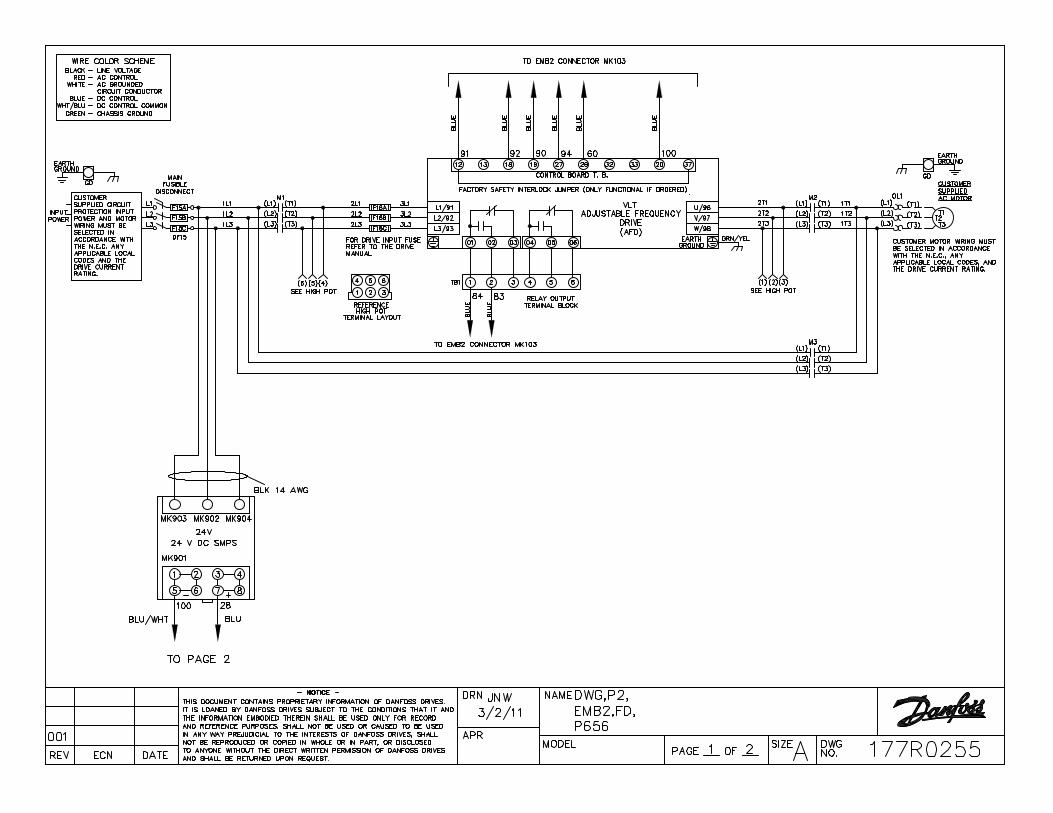
3 177U9498 - 15HP, 460/3/60, Danfoss, FC, 102, VFD, NEMA, 1, Vertical Fused Main Disconnect Bypass
AIR CONTROL SYSTEM WITH MAKEUP WATER
1 116552 - Bell and Gossett B400 ASME Full Acceptance Bladder Tank (106 gallon)
1 113237 - 113237 TPV-1FM TANK PURGE VALVE
1 5360-05F-12-003 - Bell and Gossett R-5F Flanged Rolairtrol Air Separator w/strainer
1 5358-002-00-002 - 5358-002-00-002 MBV-3L 3"SRS/ROL BLOWDOWN VALVE
1 113021 - Bell and Gossett 87 Air Vent 0.50F x 0.75M
1 113076 - Bell and Gossett 107A High Capacity Air Vent 0.75"
1 MUA075-H-075-100-D - HyFab Makeup Assembly, High Pressure, 3/4 in, 100 psi relief, 3/4" X 2" BRASS NIPPLE (MUA075-H, 110126, 4ALF-104-A2F, 222093x2)
HEATING WATER BOILERS WITH VARIABLE SPEED PUMP, GAS REGULATORS, AND VENT MATERIAL – PRICE INCLUDES COMBUSTION ANALYSIS AND STARTUP OF BOILERS
3 FBN2001 - Lochinvar Crest Condensing Boiler natural gas fired with 2,000,000 Btu/Hr input, 1,924,000 Btu/Hr output. Condensing design with 96.2% AHRI Thermal Efficiency, 25:1 Turndown, ASME Stainless Steel HX, 316L SS Fire Tubes, ASME relief valve
3 100289581 - Condensate Neutralization Kit

Page 2 of 2
3 100208567 - Wireless Outdoor Sensor
3 100157649 - BMS Communications Gateway - BACnet IP
3 100269923 - Step Down Gas Regulator
3 100208412 - ECM Variable Speed Pump, 115V
3 100267012 - Flue Adapter Kit 8" SS to CPVC

Berea Pumps & Accy / Berea HS HVAC Upgrades
HWP-1/2/3
WIZE-C5F8F5 07/20/2021
James M. Pleasants Company
(336) 378-9911
Model: 3EB
314 US gpm
80 ft
24 ft
76 %
69.5 %
10.25 in
15 hp
8.37 bhp
1800 rpm
1588 rpm
5 ft
87.9 ft
82.3 US gpm
412 US gpm
68 ºF
Water
762 lbs
5.92 ft²
Energy Efficiency Ratings:Pump & Motor PEIcl: 0.92 ERcl: 8Pump, Motor & Drive: PEIvl: 0.45 ERvl: 55
3EB1588 RPM
Performance curve meets 14.6 / ISO 9906 acceptance criteria WIZE-C5F8F5

Constant Speed Curve (1750 rpm)
Operating Point
Flow: 314 US gpm Head: 80.2 ft Speed: 1588 Efficiency: 76% Point BHP: 8.37 End Of Curve: 54.3%
Maximum Duty Point (at rated motor speed)
Flow: 346 US gpm Head: 97.4 ft Speed: 1750 Efficiency: 76% Point BHP: 11.2 NOL Flow: 638 US gpm Runout Flow: 638 US gpm NOL (BHP): 14.6
WIZE-C5F8F5

WIZ
E-C
5F8
F5

WIZE-C5F8F5

Berea Pumps & Accy / Berea HS HVAC Upgrades
HWP-1/2
WIZE-C5F8F5 07/20/2021
James M. Pleasants Company
(336) 378-9911
EE-3X
4.0 in
4.0 in
1.2'
Flanged/Flanged
372
Water
68 ºF
EE-3X
WIZE-C5F8F5

Berea Pumps & Accy / Berea HS HVAC Upgrades
HWP-1/2
WIZE-C5F8F5 07/20/2021
James M. Pleasants Company
(336) 378-9911
3DS-4B
4.0 in
4.55'
100%
Flanged
191
3DS-4B
WIZE-C5F8F5

1 of 11 Quote Number
Submittal Schedule This schedule includes the products supplied as part of this submittal.
Schedule Tag /
Item Qty Equipment ID
Motor HP
Drive Data
Product ID HP Output Amps
Voltage Enc. Frame Size
1 1 15 177U9498 15 21 460 VAC NEMA 1 P2
Configuration: Danfoss VLT HVAC drives with three-contactor electro-mechanical bypass, main disconnect and drive fusing, 100kA SCCR

2 of 11 Quote Number
ELECTRO-MECHANICALLY CONTROLLED BYPASS (EMB) FEATURES
General Features
All optional features shall be built, mounted and tested by Danfoss. The factory warranty will apply to the entire assembly as shipped. All options will carry a UL / C-UL Enclosed Industrial Control Panel label. All optional devices will be factory tested as assembly.
Bypass Power Features
Three-Contactor bypass will be provided that allows operation of the motor via line power in the event of a failure of the VFD. Motor control selection shall be through either a VFD output contactor or a bypass contactor that is interlocked to ensure that both contactors are not energized simultaneously.
Main input disconnect will be provided that removes power from both the bypass and VFD.
VFD-only, fast acting input fuses will be provided.
Overload protection will be supplied in bypass mode.
o Adjustable current setting for complete motor protection when operating on line power.
o Overload protection shall include phase loss and phase imbalance protection.
o Visual indication of an overload trip condition shall be displayed on the VFD keypad.
o Resetting an overload trip condition shall not require the opening of the enclosure door for safety reasons and shall be accomplished via a digital input, door mounted device (drive keypad), or over the serial communications.
A third contactor, the drive input contactor, will be supplied. This allows powering of the VFD with the motor off or operating in bypass mode for testing, programming and troubleshooting purposes.
Main input motor rated fuses that protect the entire package will be provided.
All panels shall be marked for 100,000 amp short circuit current rating.
Bypass Interface and Control Features
Bypass or VFD selection shall be via a DRIVE – OFF –BYPASS – TEST selector switch.
A BYPASS pilot light will illuminate when operating in bypass mode.
The TEST position shall allow the ability to supply power to the drive for testing purposes while running the motor in bypass.
Selection of Bypass or VFD operation will be by any one of the following: Manually via the VFD keypad, remotely via a contact closure from the BMS system, commanded over the communication network or automatic bypass operation based on VFD programming.
Bypass package will include an External Safety interlock that will disable motor operation in either bypass or VFD mode when open.
EMB2 control package will be provided. This package includes the following features:
o There shall be complete Common Start/Stop command when operating in either Bypass or VFD mode. While operating in Bypass mode, the keypad shall allow the selection of Hand or Remote motor starting. In Hand and Bypass modes, pushing the keypad start button shall initiate motor operation via line power. When in Remote and Bypass modes are selected, the motor shall start just as it would have in VFD and Remote mode. This start source can be via either a hardwired start command, the VFD’s real time clock or a command over BAS communication. This feature allows energy savings over standard bypass packages by allowing nighttime shutdown schedules and load shedding even with a VFD failure. Bypass packages that only allow common remote start / stop command when this command is hardwired to the package are not acceptable.
o Selectable Run Permissive logic shall operate in either VFD or bypass operation. When

3 of 11 Quote Number
activated, any command to start the motor, in either Hand Bypass, Remote Bypass, Hand VFD or Remote VFD shall not start the motor, but instead close a relay contact that is used to initiate operation of another device, such as an outside air damper. A contact closure from this device shall confirm that it is appropriately actuated and the motor shall then start.
o Firemode operation input shall be available. When closed, the motor will run in bypass mode regardless of operating mode selected and will ignore calls to stop. These include the opening of the external safety interlock circuit or the tripping of the motor overload.
Additional Protective features
In additional to the power and operational protective features listed above, each bypass will include the following:
Low voltage contactor operation shall be maintained to 70% of the package’s nominally rated voltage. This will ensure VFD operation on low voltage conditions that would otherwise be interrupted due to contactor dropout.
The VFD shall be able to operate the motor at a reduced load with the loss of any one of the three phases of power. Contactors shall remain closed regardless of which phase is lost. This will ensure VFD operation on single-phase conditions that would otherwise be interrupted due to contactor dropout.
WARRANTY
The VLT HVAC Drive packages for this project carry an 18-month on-site warranty from the date of shipment. This warranty includes parts, labor, travel, and expenses.
STARTUP
If specified, a Danfoss authorized service technician will perform a professional startup service.

4 of 11 Quote Number
DRIVE FEATURES – OPERATOR INTERFACE
The VLT®HVAC Drive
The VLT HVAC Drive Series is a microprocessor-based, high frequency IGBT-based, PWM AC drive with control functions and software designed solely for the unique needs of HVAC systems. The VLT HVAC Drive uses state-of-the-art Voltage Vector Control to supply full rated motor voltage at rated load and frequency, full motor performance without derating, high efficiency for both drive and motor, and a nearly perfect output sine wave. The diode-bridge rectifier and DC-link reactor provide a high displacement power factor at all speeds and loads and minimize power line harmonics. The VLT HVAC Drive utilizes a common user interface for all units.
Fully Graphic, Multilingual Display
The VLT HVAC Drive uses a large, bright, backlit graphic display to provide complete drive information at a glance. The logical arrangement of all elements simplifies the setup, operation and monitoring of the drive. Choose from 25 different items to display, including input reference, motor current, hours run, output frequency, horsepower, kW or kWh. Or select from custom units, such as GPM or HP and calibrate the maximum value to the maximum frequency of the unit. After programming one drive, the keypad can be used to transfer the same settings to all other drives. Drive can run without the keypad in place to assure tamper-proof operation. Drive status is shown even with the keypad removed.
LED Indication
Three LEDs are provided on the VLT HVAC Drive for indication of power applied, warning and fault. Upon power up, all LEDs will briefly light as a lamp test.
Alarm – Will flash red when the drive has registered a fault condition which has caused the drive to shut down.
Warning – Will flash yellow to indicate a situation exists that exceeds the normal drive/system parameters, and if that condition continues, a trip may be imminent.
On – Will glow green to indicate that the VFD is connected to AC power (line voltage is present).
Operating Keys
Hand On – Starts the drive regardless of remote start/stop contact (assuming safety interlock is closed). The speed of the drive will generally be controlled manually via the keypad "+" and "−" buttons.
Off – Shuts the drive down regardless of other commands.
Auto/On – The drive will start and stop via the external contact closure (building automation time clock). The speed is generally controlled via the building automation signal (4 to 20 mA, 0 to 10 V DC, etc.).
Reset – Will reset any trip level fault (not trip lock) if the drive is not set for infinite automatic fault resets.

5 of 11 Quote Number
Directional Keys
Right / Left / Up / Down arrows – Used as the electronic potentiometer to manually control the speed in the Hand/Start mode. All four keys are active during operation as well as programming. They provide the ability to move the cursor around the display, or sequence through display values.
Programming Keys
Status – Used to display operational data and status.
Cancel – Used to cancel the last programming command so the change is not carried out.
OK – Used to confirm that the last programming change should be saved to memory.
Back – Used to exit present display or menu to the previous display or menu.
Quick Menu – Used for programming the VLT HVAC Drive for the most typical applications.
Main Menu – Used to access all parameters for programming. It can switch directly from this mode to quick menu.
Alarm Menu – Used to access all fault and warning data.
Info Key – Accesses an on-board manual that gives detailed explanation of a parameter.
PROGRAM OPTIONS
Application-Specific Software
The VLT HVAC Drive was designed specifically for the HVAC market. This specialization has allowed Danfoss to factory program and configure the VLT HVAC Drive to make it ready to use, out of the box. This eliminates the time-consuming and often confusing job of selecting the correct parameters in the field. For the advanced user, the parameters are logically grouped, making modifications simple. Customized text fields are available to show user-specific data. Four independent setups are available for unmatched flexibility.
Menu Structure
Quick Setup Menu – Contains the 14 required setup parameters to easily start the application.
HVAC Application Menu – Easy access to the most relevant parameters for each of the most common HVAC applications.
Personal Menu – Contains up to 20 user-selectable parameters for customized access.
Changes Made Menu – Provides easy access to previously modified parameters
Keypad Features
Hot-pluggable with upload and download capabilities
On-screen scroll bars and graphs
Up to five separate meters displayed simultaneously
Two-level password protection
Plain language alarms and warnings
Remote keypad mounting kits available
USB Connectivity
The VLT HVAC Drive can be remotely commissioned and monitored through a standard USB connection and MCT 10 PC software.
Agency listing:
All drives and option packages are factory built and carry UL and C–UL listings.
All drives and option packages are built in ISO 9000 and 14001 certified facilities.

6 of 11 Quote Number
DRIVE FEATURES – MOTOR AND DRIVE INTERACTION
Constant-Torque Start
The VLT HVAC Drive’s constant-torque start mode provides full torque to accelerate different loads until the drive reaches the setpoint. Breakaway current can be set up to 160% for up to 0.5 seconds for starting high friction loads.
Current Limit Circuit
Adjustable from 0 to 110% of the VLT HVAC Drive's rated current (factory set at 110%). If during acceleration the current required to accelerate the load exceeds the current limit, the VLT HVAC Drive will stop accelerating until the motor current is reduced to normal levels, at which time the load will continue to accelerate at the rate set by the acceleration time.
Three-Phase Output Current Measurement
The VLT HVAC Drive’s software measures output current on all three phases. Phase grounding is detected instantly. Output contactors may be repeatedly used with no damage to the drive. Multiple motors may be run from one drive.
Advanced Motor Protection
The VLT HVAC Drive features integrated electronic, thermal motor protection. The VFD calculates the motor temperature based on current, frequency, and time. This system allows for changing cooling conditions as speed and load vary. The drive can predict motor overheating and reports a % of thermal load.
Motor Preheat Circuit
This preheat function can be activated to avoid condensation on the motor windings when it is stopped.
Stall Protection
The VLT HVAC Drive provides protection against a stalled motor. When activated, this function can provide a warning or a fault condition caused by excessive motor current at low speeds.
DRIVE FEATURES
DC-Link Reactor
A dual, 5% DC-link reactor on the positive and negative rails of the DC bus is standard equipment on the VLT HVAC Drive. This reactor reduces the level of harmonics reflected back into the building power system without causing a voltage loss at the drive’s input and reducing efficiency as an external AC line reactor would. This reactor also improves input power factor. The reactor is non-saturating (linear) to provide full harmonic filtering throughout the entire load range. In performance, the DC-link reactor is equivalent to a 5% AC line reactor.
Power Line Protection
Power line voltage surge protection is provided by means of input Metal Oxide Varistors (MOVs). This protects the diodes in the VLT HVAC Drive’s 3-phase full wave diode bridge. The DC-link reactor also acts to reduce input current caused by power line disturbances.
Sleep Mode
Automatically stops the drive when speed drops below set "sleep" level for specified time. Automatically restarts when speed command exceeds set "wake" level. Saves energy and reduces wear on driven equipment.

7 of 11 Quote Number
Run Permissive Circuit
Ability to accept a "system ready" signal assures that dampers or other auxiliary equipment are in the proper state for drive operation. This feature also provides the ability for the drive to send a “start signal applied” signal to the system to notify the auxiliary equipment of the drive’s request to start.
Firefighter’s Override Mode
Overrides all other commands to provide desired operation. Ignores most alarms including overload, overcurrent, overtemperature, and phase loss. When used with bypass, selectable to run from drive, from bypass, or switch from drive to bypass in the event of a drive failure.
Acceleration / Deceleration Rates
The VLT HVAC Drive can provide four individually controlled sets of acceleration/deceleration rates each from 1 to 3600 seconds. The shape of these curves may be automatically contoured to prevent tripping.
Plenum Rated
The VLT HVAC NEMA 1 or NEMA 12 drive is recognized by UL for installation in air handling compartments.
Auto Restarts
The VLT HVAC Drive can be automatically restarted up to 20 times or infinitely at 0 to 600 second intervals. If the application causes the drive to trip more than the number of trials set, the drive will stop operating and display the fault on the display screen. A manual reset will be required by means of the reset key, a digital input, or EIA–485 command. In cases of severe trips, as a safety feature, the drive's input power may have to be cycled to restart a fault.
Carrier Frequency
By using IGBTs, the VLT HVAC Drive can employ high switching frequencies, so the motor current is practically sinusoidal. Audible motor noise can also be minimized by adjusting the switching frequency. These frequencies can be set or adjust themselves automatically to fit the application.
Input Power
The VLT HVAC Drive is equipped with an automatic sustained power or phase loss circuit. The VLT HVAC Drive will provide a full rated output with an input voltage as low as 90% of the nominal. The drive will continue to operate with reduced output with an input voltage as low as 164 volts for 208/230 volt units, 313 volts for 460 volt units, and 394 volts for 600 volt units.
Automatic Motor Adaptation (AMA)
Knowing motor stator resistance, the drive automatically optimizes performance and efficiency. The motor does not have to be run or decoupled from the load for the AMA setup to be performed.
Automated Frequency Avoidance / Critical Frequency Lockouts
For applications where it may be necessary to avoid specific frequencies due to mechanical resonance problems in the driven equipment, the VLT HVAC Drive, with its Critical Frequency Lockout Function, makes it possible to set up to four different frequency ranges which will be avoided during operation of the drive. This feature can be programmed by simply activating the feature and pushing OK at the top and bottom points that you wish to avoid.
Each critical frequency setting can avoid a frequency band which is from 1 to 100 Hz wide. If the reference signal defines that the VLT HVAC Drive is to operate within this critical frequency range, the critical frequency lockout function will keep the drive operating continuously within this range.
When the frequency reference signal rises above the critical frequency maximum limit, the VLT HVAC Drive will allow the motor to accelerate through the critical frequency at the rate set by the acceleration rate.

8 of 11 Quote Number
Automatic Energy Optimization Circuitry
The Automatic Energy Optimization (AEO) function adapts the output of the drive to the specific motor and load connected. This circuit optimizes the system efficiency as system loads change. The AEO function regulates the output voltage on the basis of the reactive current and the effective current. A savings of 3 to 10% in power consumption can be obtained with this function.
Preset Speeds
The VLT HVAC Drive allows for a maximum of 16 programmable preset speeds to be selected from the digital inputs.
Energy Monitoring
Real energy savings are always available without the additional expense of external equipment.
Real-Time Clock
Adds sophisticated performance to basic control schemes for increased comfort and energy savings.
Automatic High Ambient Derate
If the ambient temperature exceeds the normal limit, the drive can be set to warn of its overtemperature and continue to run, keeping the HVAC system functional. To control its temperature, the drive will reduce the output carrier frequency and then, if necessary, reduce the output current.
Preventive Maintenance Scheduling
The VLT HVAC Drive can monitor system usage and notify the operator when preventive maintenance is required.
Intelligent HVAC Controller
Four auto-tuning PIDs control the drive and up to three other devices, eliminating external controllers and reducing cost.
Proportional: The proportional gain dictates the rate at which the deviation between actual and desired feedback signal is corrected. The higher the gain, the faster the response, but too high a gain can cause hunting and a large overshoot.
Integral Time: The integral time continually compares the feedback value with the desired setpoint over time to make sure the setpoint is reached. The greater the integral time, the longer it takes to actually achieve the setpoint, but improves the system stability.
Derivative: The derivative function monitors the rate at which the feedback is closing on the desired setpoint and slows the rate of approach to prevent overshooting. This function allows rapid accurate system control.
Built-in Communications
The VLT HVAC Drive is fully equipped for serial communication (EIA–485). Up to 31 drives can be connected to one serial bus up to 5,000 feet long.
Communicates directly with BACnet MS/TP, Johnson Controls Metasys (N2), Siemens Building Technologies System 600 (FLN), and Modbus RTU systems with no hardware changes or additional costs.
Optional communications include LonWorks with the addition of an Option A card.
Broken Belt, Loss of Load
A minimum motor current value can be set to indicate the motor is not using any more current than to run at idle. This can be used to indicate a broken belt or coupler. This feature can also be used to detect when a motor is disconnected from the drive.

9 of 11 Quote Number
SPECIFICATIONS
Drive Input Power
Input voltage, 3 phase ............................................. 200–240, or 380–460, or 525–600 VAC
Input voltage range for full output ........................... Nominal ±10%
Undervoltage trip point ............................................ 164, 313 VAC, or 394 VAC
Overvoltage trip point .............................................. 299, 538, or 690 (792 for 100 HP and above) VAC
Input frequency ....................................................... 50 or 60 Hz, ± 2 Hz
Displacement Power factor ..................................... 0.98 or greater at all speeds and loads
Total Power factor ................................................... 0.90 or greater at full load and nominal motor speed
Drive Output Power
Output frequency ..................................................... Selectable 0 to 120 Hz
Motor voltages ......................................................... 200, 208, 220, 230; 380, 400, 415, 440, 460; 550 or 575 VAC
Continuous output current ....................................... 100% rated current
Output current limit setting ...................................... Adjustable to 110% of drive rating
Current limit timer .................................................... 0 to 60 seconds or infinite
Adjustable maximum speed .................................... From minimum speed setting to 120 Hz
Adjustable minimum speed ..................................... From maximum speed setting to 0 Hz
Acceleration time ..................................................... To 3,600 seconds to base speed
Deceleration time .................................................... To 3,600 seconds from base speed
Breakaway torque time ........................................... 0.0 to 0.5 seconds (1.6 times motor nameplate current)
Start voltage ............................................................ 0 to 10%
DC braking time ...................................................... 0 to 60 seconds
DC braking start ...................................................... 0 to maximum frequency
DC braking current .................................................. 0 to 50% of rated motor current
Environmental limits:
Efficiency ................................................................. 97% or greater at full load and nominal motor speed
Ambient operating temperature .............................. 14°F to 113°F (−10°C to 45°C) frames A2–C2; 14°F to 104°F (−10°C to 40°C) frames D1–E1
Humidity ................................................................ < 95%, non-condensing
Altitude: maximum without derating ........................ 3,300 ft. (1,000 m)
Drive and options enclosure(s) ............................... NEMA/UL Types 1, 12, 3R; as noted

10 of 11 Quote Number
Software
Lost speed reference action .................................... Selectable to go to a preset speed, go to maximum speed, stay at last speed, stop, turn off, or stop and trip
Time delay for lost speed reference action ............. 1 to 99 seconds
Adjustable auto restart time delay ........................... 0 to 600 seconds
Automatic restart attempts ...................................... 0 to 20 or infinite
Automatic restart time delay .................................... 0 to 600 seconds between each attempt
Relay ON delay and relay OFF delay ..................... 0 to 600 seconds
Maximum number of preset speeds ........................ 16
Maximum number of frequency stepovers .............. 4
Maximum stepover width ........................................ 100 Hz
Maximum number of accel rates ............................. 4
Maximum number of decel rates ............................. 4
Delayed Start .......................................................... 0 to 120 seconds
Protections:
Low frequency and high frequency warnings.......... 0 to 120 Hz
Low current and high current warnings ................... 0 to maximum current
Low reference and high reference warnings ........... −999,999 to 999,999
Low feedback and high feedback warnings ............ −999,999 to 999,999
Ground fault ............................................................ Protected
Motor stall ................................................................ Protected
Motor overtemperature ............................................ Protected (Predictive motor temperature)
Motor Condensation ................................................ Protected (Motor pre-heat circuit)
Pump No-Flow ........................................................ Protected
Pump end-of-curve .................................................. Protected
Dry pump ................................................................ Protected
Short-cycle .............................................................. Protected
Motor overload ........................................................ Protected (Programmable action)
Vibration protection ................................................. Protected (Programming automated)

11 of 11 Quote Number
Control Connections
Follower signal, analog input................................... 2; selectable voltage or current, direct and inverse acting
Programmable digital inputs .................................... 6 (2 can be used as digital outputs)
Programmable analog outputs ................................ 1; 0/4 to 20 mA
Programmable relay outputs ................................... 2 standard Form C 240 V AC, 2 A; 1 or 3 additional optional
Auxiliary voltage ...................................................... +24 V DC, maximum 200 mA
Control Optional
MCB 101 General Purpose I/O ............................... 3 DI, 2 DO, 2 AI (voltage), and 1 AO (current)
MCB 105 Relay Card .............................................. 3 standard Form C 240 V AC, 2 A
MCB 107 24V DC Supply ........................................ Allows external 24 V DC power to be connected to the VLT HVAC Drive
MCB 109 Analog I/O ............................................... 3 AO(voltage), 3 AI(voltage or PT1000 or NI1000), Battery backup
12345678
12345678
A
B
C
D
A
B
C
D
4401 N. BELL SCHOOL RD. LOVES PARK, ILLINOIS 61111 USA (815) 639-8600 FAX (815) 639-8000
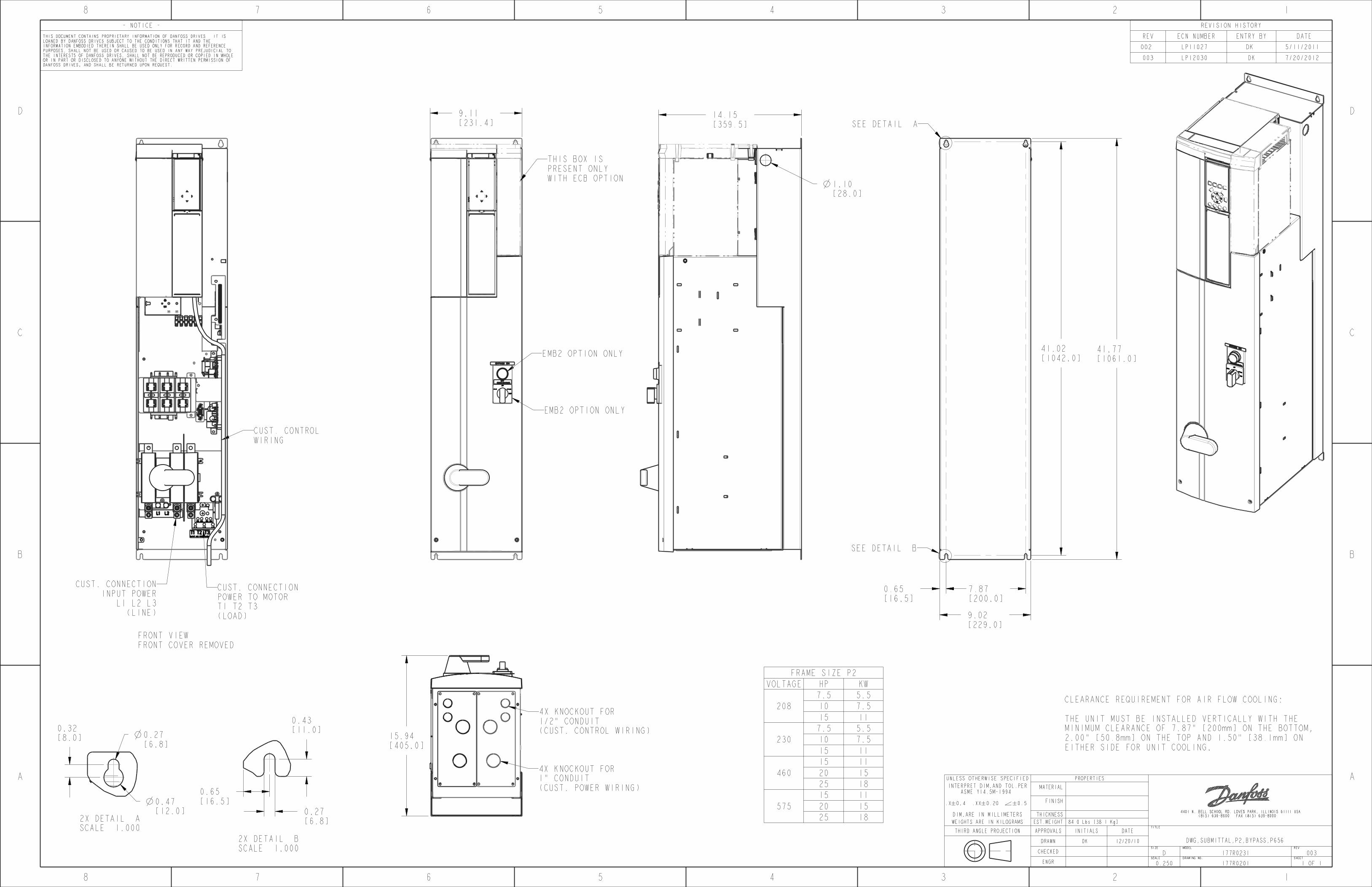
9.11[231.4]
14.15[359.5]
1.10[28.0]
41.02[1042.0]
41.77[1061.0]
9.02[229.0]
7.87[200.0]
0.65[16.5]
15.94[405.0]
0.65[16.5]
0.27[6.8]
0.43[11.0]
0.47[12.0]
0.32[8.0] 0.27
[6.8]
1 OF 1177R02010.250ENGRSHEETDRAWING NO.SCALE
003177R0231DCHECKEDREVMODELSIZE
12/20/10DK DRAWN
DATEINITIALSAPPROVALSTHIRD ANGLE PROJECTIONTITLE
84.0 Lbs [38.1 Kg]EST.WEIGHTWEIGHTS ARE IN KILOGRAMS
THICKNESSDIM.ARE IN MILLIMETERS
.X 0.4 .XX 0.20 0.5 FINISH
INTERPRET DIM.AND TOL.PERASME Y14.5M-1994
MATERIAL
PROPERTIESUNLESS OTHERWISE SPECIFIED
REVISION HISTORY
DATEENTRY BYECN NUMBERREV
5/11/2011 DK LP11027 002
7/20/2012 DKLP12030 003
- NOTICE -
THIS DOCUMENT CONTAINS PROPRIETARY INFORMATION OF DANFOSS DRIVES. IT IS LOANED BY DANFOSS DRIVES SUBJECT TO THE CONDITIONS THAT IT AND THE INFORMATION EMBODIED THEREIN SHALL BE USED ONLY FOR RECORD AND REFERENCE PURPOSES, SHALL NOT BE USED OR CAUSED TO BE USED IN ANY WAY PREJUDICIAL TO THE INTERESTS OF DANFOSS DRIVES, SHALL NOT BE REPRODUCED OR COPIED IN WHOLE OR IN PART OR DISCLOSED TO ANYONE WITHOUT THE DIRECT WRITTEN PERMISSION OF DANFOSS DRIVES, AND SHALL BE RETURNED UPON REQUEST.
FRAME SIZE P2VOLTAGE HP KW
2087.5 5.510 7.515 11
2307.5 5.510 7.515 11
46015 1120 1525 18
57515 1120 1525 18
CLEARANCE REQUIREMENT FOR AIR FLOW COOLING: THE UNIT MUST BE INSTALLED VERTICALLY WITH THEMINIMUM CLEARANCE OF 7.87" [200mm] ON THE BOTTOM,2.00" [50.8mm] ON THE TOP AND 1.50" [38.1mm] ON EITHER SIDE FOR UNIT COOLING.
FRONT VIEWFRONT COVER REMOVED
DWG,SUBMITTAL,P2,BYPASS,P656
THIS BOX ISPRESENT ONLYWITH ECB OPTION
EMB2 OPTION ONLY
EMB2 OPTION ONLY
4X KNOCKOUT FOR1/2" CONDUIT(CUST. CONTROL WIRING)
4X KNOCKOUT FOR1" CONDUIT(CUST. POWER WIRING)
SEE DETAIL A
SEE DETAIL B
2X DETAIL ASCALE 1.000
2X DETAIL BSCALE 1.000
CUST. CONNECTIONINPUT POWER
L1 L2 L3(LINE)
CUST. CONNECTIONPOWER TO MOTORT1 T2 T3(LOAD)
CUST. CONTROLWIRING


Berea HS Boiler Rep.
Greenville Co Schools
Bill Knight
JMP - Tigue Garick
33
HWP-1/2/3HWP-1/2/3

DISCHARGE HOSE PORT (1X)• 6” THREADED PIPE• ¼” FXF BALL VALVE• ELBOW HOSE ADAPTOR
GAUGE KIT ASSEMBLY INSTRUCTIONS• INSTALL WITH THREAD SEALANT OR TEFLON TAPE ON THREADS TO AVOID LEAKS• CUT EXCESS HOSE TO FIT. LEAVE SOME SLACK FOR A NATURAL BEND AND AVOID KINKS
AND SHARP BENDS• POSITION VALVE HANDLES TO AVOID PINCH POINTS AND ACCOUNT FOR INSULATION• KIT INCLUDES EXTRA PARTS FOR DIFFERENT CONFIGURATIONS, NOT ALL WILL BE USED
GAU
GE
KIT
ASSE
MBL
Y DI
AGRA
MHF
GK-
1510
L 3
PORT
GAUGE CROSS ASSEMBLY (1X)• 4” and 6” THREADED PIPE• ¼” ELBOW• ¼” STREET ELBOW• ¼” MXF BALL VALVE• ¼” THREADED CROSS• MALE HOSE ADAPTOR• ELBOW HOSE ADAPTOR• PRESSURE GAUGE• BRASS GAUGE SNUBBER
SUCTION DIFFUSER HOSE PORT (1X)• 4” THREADED PIPE• ¼” FXF BALL VALVE• ELBOW HOSE ADAPTOR
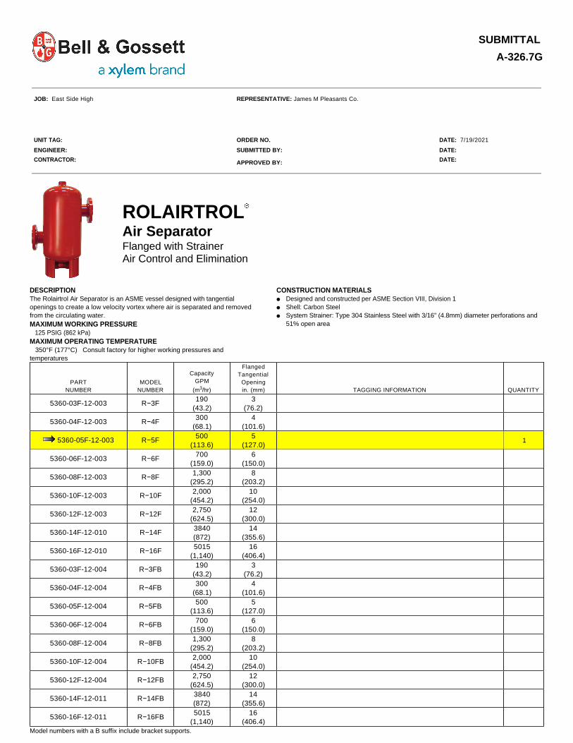
SUBMITTAL
A-326.7G
JOB: East Side High REPRESENTATIVE: James M Pleasants Co. UNIT TAG: ORDER NO. DATE: 7/19/2021 ENGINEER: SUBMITTED BY: DATE: CONTRACTOR: APPROVED BY: DATE:
Model numbers with a B suffix include bracket supports.
ROLAIRTROL
Air Separator
Flanged with Strainer Air Control and Elimination
DESCRIPTION The Rolairtrol Air Separator is an ASME vessel designed with tangential openings to create a low velocity vortex where air is separated and removed from the circulating water. MAXIMUM WORKING PRESSURE 125 PSIG (862 kPa) MAXIMUM OPERATING TEMPERATURE 350°F (177°C) Consult factory for higher working pressures and temperatures
CONSTRUCTION MATERIALS ● Designed and constructed per ASME Section VIII, Division 1● Shell: Carbon Steel● System Strainer: Type 304 Stainless Steel with 3/16" (4.8mm) diameter perforations and
51% open area
PART NUMBER
MODEL NUMBER
Capacity GPM
(m3/hr)
Flanged Tangential
Opening in. (mm) TAGGING INFORMATION QUANTITY
5360-03F-12-003 R−3F190
(43.2)3
(76.2)
5360-04F-12-003 R−4F300
(68.1)4
(101.6)
5360-05F-12-003 R−5F500
(113.6)5
(127.0) 1
5360-06F-12-003 R−6F700
(159.0)6
(150.0)
5360-08F-12-003 R−8F1,300
(295.2)8
(203.2)
5360-10F-12-003 R−10F2,000
(454.2)10
(254.0)
5360-12F-12-003 R−12F2,750
(624.5)12
(300.0)
5360-14F-12-010 R−14F3840 (872)
14 (355.6)
5360-16F-12-010 R−16F5015
(1,140)16
(406.4)
5360-03F-12-004 R−3FB190
(43.2)3
(76.2)
5360-04F-12-004 R−4FB300
(68.1)4
(101.6)
5360-05F-12-004 R−5FB500
(113.6)5
(127.0)
5360-06F-12-004 R−6FB700
(159.0)6
(150.0)
5360-08F-12-004 R−8FB1,300
(295.2)8
(203.2)
5360-10F-12-004 R−10FB2,000
(454.2)10
(254.0)
5360-12F-12-004 R−12FB2,750
(624.5)12
(300.0)
5360-14F-12-011 R−14FB3840 (872)
14 (355.6)
5360-16F-12-011 R−16FB5015
(1,140)16
(406.4)

ROLAIRTROL - Flanged with Strainer A-326.7G
*Indicates measurements for models that have optional support brackets
†Bracket weight should be added to flood weight and approximate shipping weight for models that are being supplied with optional support brackets.
IMPORTANT NOTES:
DIMENSIONS in Inches (mm) AND WEIGHTS in Lbs (kg.)
MODEL NUMBER A B C D E F G H J K L* M* N* Cv
Strainer Free Area
in
in22)
Approx. Volume in
Gallons (Ltr.)
Approx. Shpg. Wt.
in Lbs. (Kg)
Flood Wt.Less
Bracket in Lbs. (Kg)
Bracket Wt. in
Lbs. (Kg)†
R−3F (B)26-7/8 (683)
8 (203)
10-13/16 (275)
8-1/16 (205)
10-3/4 (273)
22-3/4 (578)
3-5/8 (92)
1-1/4 (32)
3 (76)
12 (305)
13-3/8 (340)
14 (356)
2 (51)
11990
(58,064)7
(26)130 (59)
188 (85)
9 (4)
R−4F (B)31-
7/16 (799)
10 (254)
11-15/16 (303)
9-1/2 (241)
12-3/4 (324)
20-1/2 (521)
4-1/8 (105)
1-1/2 (38)
3 (76)
14 (356)
15-3/8 (391)
16 (406)
2 (51)
257120
(77,419)13
(49)170 (77)
278 (126)
9 (4)
R−5F (B)
37 (940)
12 (305)
14-1/16 (357)
10-15/16 (278)
16 (406)
23-3/4 (603)
5-1/4 (133)
1-1/2 (38)
3 (76)
16 (406)
18-1/2 (470)
19-3/8 (492)
2 (51)
398165
(106,451)25
(95)220
(100)429
(194)9
(4)
R−6F (B)44-
1/16 (1119)
14 (356)
16-13/16 (427)
13-1/4 (337)
18 (457)
25-3/4 (654)
5-11/16 (144)
1-1/2 (38)
3 (76)
19 (483)
22-1/8 (562)
21-1/4 (540)
2 (51)
632205
(132,258)34
(129)295
(134)579
(262)9
(4)
R−8F (B)54
(1372)18
(457)19-7/16
(494)
16-9/16 (421)
24 (610)
31-3/4 (806)
7-11/16 (195)
2 (51)
3 (76)
23 (584)
26 (660)
29-1/2 (749)
2 (51)
1,020325
(209,677)90
(341)460
(209)1,211 (549)
30 (14)
R−10F (B)64-
11/16 (1643)
22 (559)
22-5/8 (575)
20-1/16 (510)
30 (762)
37-3/4 (959)
9-5/8 (244)
2 (51)
3 (76)
28 (711)
31-5/8 (803)
35-1/2 (902)
2 (51)
1,789475
(306,451)150
(568)845
(383)2,097 (951)
30 (14)
R−12F (B)75-3/8 (1915)
27 (686)
25-3/4 (654)
22-5/8 (575)
36 (914)
46-3/4 (1187)
11-5/8 (295)
2 (51)
3 (76)
31 (787)
37-5/8 (965)
41-1/2 (1054)
2 (51)
2,665645
(416,128)291
(1101)1160 (526)
3,588 (1627)
30 (14)
R−14F(B) 92-1/8 (2,340)
31-1/2 (800)
34-3/4 (883)
25-7/8 (657)
42 (1067)
54-1/2 (1,384)
14 (356)
2 (51)
3 (76)
32-1/2 (826)
48 (1,219)
48-1/2 (1,232)
3 (76)
3,400715
(461,286)470
(1,779)1,775 (805)
5,715 (2,592)
56 (25)
R−16F(B) 104
(3,642)36
(914)37-3/4 (959)
30-1/4 (768)
48 (1,219)
62-1/2 (1,588)
16 (406)
2 (51)
3 (76)
40 (1,016)
50 (1,270)
54-1/2 (1,384)
3 (76)
4,200919
(592,902)723
(2,737)2,417
(1,096)8,450
(3,833)56
(25)
Important Note: Dimensions not to be used for construction.
1. Consult IOM A85524 for safety and service instructions.
2. Model "R" Rolairtrol Air Separators have strainers which must be removed and cleaned after 24 hours operation, 30 days operation and as required to maintain proper system air
separation. Before installing the model "R" Rolairtrol, refer to (K) in the dimensions and weights table, which notes minimum distances to be maintained between the blowdown connection and the floor or other equipment for strainer removal.
3. Lifting lugs are for the transportation and installation of the empty vessel, and are not to be used for complete or partial support of the flood vessel.
4. The R model skirt can support the flooded weight of the vessel. Strainer Models require adequate floor clearance of skirt for removal of strainer.
5. Welding to the pressure vessel boundary will void the ASME stamp.
6. Standard Rolairtrol design up to 12" can be hung from the nozzles using hangers. Optional, factory welded, support brackets are available for an additional cost.

ROLAIRTROL - Flanged with Strainer A-326.7G
TYPICAL ROLAIRTROL SPECIFICATIONS
Refer to submittal A-329 for information on the MBV-1 manual blowdown valve.
Rolairtrol Air Separator Performance Coverage Chart
Note: Pressure drops for a range of flow are indicated on this chart. Users should select Rolairtrol using B&G published capacity guidance, and ASHRAE pipe sizing recommendations for optimal performance.
Furnish and install, as shown on plans, a centrifugal type air separator. The unit shall have _____" inlet and outlet flanged connections tangential to the vessel shell. The unit shall have an internal type 304 stainless steel strainer and air separator with 3/16" (4.8mm) perforations and 51 percent open area designed to direct accumulated air to an air vent (air elimination system) via an NPT vent connection at top of unit.
A blowdown connection shall be provided to facilitate routine cleaning. Specify B&G Model MBV-1 Rolairtrol accessory with appropriate fittings for manual blowdown.
Vessel shell diameter to be three times the nominal inlet/outlet pipe diameter, with a minimum vessel volume for sufficient velocity reduction.
The air separator must be designed, constructed and stamped for 125 psig @ 350°F (862 kPa @ 177°C) in accordance with Section VIII, Division I of the ASME Boiler and Pressure Vessel Code, and registered with the National Board of Boiler and Pressure Vessel Inspectors. The air separator(s) shall be painted with one shop coat of light gray air dry enamel
Each air separator shall be Bell & Gossett Model No. _____ Rolairtrol Air
Separator for ______ GPM ( ______ m3), Shell Dia. ______" (______ mm) and Min. Vessel Volume ______ Gal (______ liters).
Xylem Inc. 8200 N. Austin Avenue, Morton Grove, IL 60053 Phone: (847)966-3700 Fax: (847)965-8379 www.xyleminc.com/bellgossett Bell & Gossett is a trademark of Xylem Inc. or one of its subsidiaries. ESP-REP v2021.02 © 2020 Xylem Inc.

SUBMITTAL
A-342G
JOB: East Side High REPRESENTATIVE: James M Pleasants Co. UNIT TAG: ORDER NO. DATE: 7/19/2021 ENGINEER: SUBMITTED BY: DATE: CONTRACTOR: APPROVED BY: DATE:
SCHEDULE
Series "B" (ASME) Pressurized Expansion TanksVertical Not For Potable Water Systems
DESCRIPTION Series "B" expansion tanks are ASME rated precharged bladder-type pressure vessels. The Series "B" tank is designed to absorb the expansion forces of heating/cooling system water while maintaining proper system pressurization under varying operating conditions. The heavy duty bladder contains system water thereby eliminating tank corrosion and waterlogging problems.
CONSTRUCTION System Connection: Forged Steel Shell: Carbon Steel Bladder: Heavy Duty Butyl Rubber Designed and Constructed per ASME Section VIII, Division 1 MAXIMUM OPERATING LIMITS Maximum Design Pressure: 125 PSI (862kPa) Design Temperature: 240°F (115°C)
PART NUMBER
MODEL NO.
TANK AND ACCEPTANCE
VOLUME GALLONS (LITERS) TAGGING INFORMATION QUANTITY
PRESSURIZED EXPANSION
TANKSWITH SEISMIC RESTRAINTS
116550 116923 B-200 53 (200)
116551 116924 B-300 80 (300)
116552 116925 B-400 106 (400) 1
116553 116926 B-500 132 (500)
116554 116927 B-600 158 (600)
116555 116928 B-800 211 (800)
116556 116929 B-1000 264 (1000)
116557 116930 B-1200 317 (1200)
116558 116931 B-1400 370 (1400)
116559 116932 B-1600 422 (1600)
116560 116933 B-2000 528 (2000)
116793 116934 B-2500 660 (2500)
116794 116935 B-3000 792 (3000)
116795 116936 B-3500 925 (3500)
116796 116937 B-4000 1057 (4000)
116819 116938 B-5000 1321 (5000)
116841 116939 B-7500 1980 (7500)
116842 116940 B-10000 2640 (10000)
116843 116941 B-15000 3963 (15000)
TYPICAL SPECIFICATION Furnish and install as shown on plans a _____ gallon ( _____ liter) _____" ( _____ mm) diameter x _____" ( _____ mm) high pre-charged steel expansion tank with replaceable heavy duty Butyl rubber bladder. The tank shall have a _____" NPT system connection, _____" NPT drain, and a .302"-32 charging valve connection (standard tire valve) to facilitate the on-site charging of the tank to meet system requirements.
The tank shall be fitted with lifting rings and a floor mounting skirt for vertical installation. The tank must be constructed in accordance with Section VIII of the ASME Boiler and Pressure Vessel Code and stamped 125 PSI (862 kPa) working pressure. Each tank shall be Xylem − Bell & Gossett Model No. _______

ASME EXPANSION TANKS - PRESSURIZED (Air Elimination) A-342G
NOTE:
Tanks are factory pre-charged at 12 psi (83 kPa)
Allow a minimum of 18"(457.2mm) clearance for system piping.
Sight glass and seismic restraints available on request.
Tanks can be installed in the horizontal position with the system connection located below the horizontal centerline of the tank.
OPTIONAL SEISMIC RESTRAINTS (FIG.2 & 3) − DIMENSIONS IN INCHES (MM)
TANK DIAMETER G H I J
24"9/16 (14)
21 (533)
2 (51)
2 (51)
30"7/8 (22)
28 (711)
4 (102)
4 (102)
36"7/8 (22)
34 (864)
4 (102)
4 (102)
48"7/8 (22)
46 (1168)
4 (102)
4 (102)
54"7/8 (22)
46 (1168)
4 (102)
4 (102)
60"7/8 (22)
46 (1168)
4 (102)
4 (102)
72"1
(25)58
(1473)4
(102)4
(102)
DIMENSIONS IN INCHES (MM) AND WEIGHTS IN LBS. (KG) (FIG. 1)PART NUMBER
MODEL NUMBER A B
C NPTF D E F
APPROX. SHPG. WT.
APPROX. WT* 100% FULLPRESSURIZED EXPANSION TANKS WITH SEISMIC RESTRAINTS
116550 116923 B-200 24 (610) 36-7/8 (936) 1 3/4 19 (483) 3/16 (5) 192 (87) 629 (285)
116551 116924 B-300 24 (610) 50-7/8 (1292) 1 3/4 19 (483) 3/16 (5) 268 (122) 928 (421)
116552 116925 B-400 24 (610) 64-3/4 (1644) 1 3/4 19 (483) 3/16 (5) 309 (140) 1184 (537)
116553 116926 B-500 24 (610) 78 (1981) 1 3/4 19 (483) 3/16 (5) 328 (149) 1417 (643)
116554 116927 B-600 30 (762) 63-3/4 (1619) 1-1/2 1 24 (610) 3/16 (5) 510 (232) 1814 (823)
116555 116928 B-800 30 (762) 81-3/4 (2076) 1-1/2 1 24 (610) 3/16 (5) 656 (297) 2306 (1046)
116556 116929 B-1000 36 (914) 73 (1854) 1-1/2 1-1/4 30 (762) 3/16 (5) 691 (313) 2869 (1301)
116557 116930 B-1200 36 (914) 85-3/8 (2169) 1-1/2 1-1/4 30 (762) 3/16 (5) 779 (353) 3394 (1539)
116558 116931 B-1400 36 (914) 97-3/4 (2483) 1-1/2 1-1/4 30 (762) 3/16 (5) 905 (410) 3958 (1795)
116559 116932 B-1600 48 (1219) 69-1/8 (1756) 1-1/2 1-1/2 42 (1067) 1/4 (6) 1183 (537) 4665 (2116)
116560 116933 B-2000 48 (1219) 84 (2145) 1-1/2 1-1/2 42 (1067) 1/4 (6) 1264 (573) 5620 (2549)
116793 116934 B-2500 48 (1219) 100-7/8 (2562) 2 1-1/2 42 (1067) 1/4 (6) 1445 (655) 6890 (3125)
116794 116935 B-3000 48 (1219) 118-1/8 (2562) 2 1-1/2 42 (1067) 1/4 (6) 1630 (739) 8164 (3703)
116795 116936 B-3500 54 (1372) 111 (2820) 2 1-1/2 42 (1067) 1/4 (6) 2110 (957) 9741 (4418)
116796 116937 B-4000 54 (1372) 124-1/2 (3163) 2 1-1/2 42 (1067) 1/4 (6) 2230 (1011) 10950 (4967)
116819 116938 B-5000 60 (1524) 128 (3251) 2 1-1/2 42 (1067) 1/4 (6) 2450 (1111) 13403 (6079)
116841 116939 B-7500 72 (1829) 127 (3326) 3 1-1/2 54 (1372) 3/8 (10) 4000 (1814) 20500 (9299)
116842 116940 B-10000 72 (1829) 159 (4039) 3 1-1/2 54 (1372) 3/8 (10) 4900 (2223) 26890 (12197)
116843 116941 B-15000 72 (1829) 233 (5918) 3 1-1/2 54 (1372) 3/8 (10) 6000 (2721) 39010 (17695)
Dimensions are subject to change. Not to be used for construction purposes unless certified.*Approximate weight 100% full occurs if bag fails or if air charge is lost.
Xylem Inc. 8200 N. Austin Avenue Morton Grove, IL 60053 Phone: (847)966-3700 Fax: (847)965-8379 www.bellgossett.com Bell & Gossett is a trademark of Xylem Inc. or one of its subsidiaries. ESP-REP v2021.02 © 2013 Xylem Inc.

SUBMITTAL
A-338G
JOB: East Side High REPRESENTATIVE: James M Pleasants Co. UNIT TAG: ORDER NO. DATE: 7/19/2021 ENGINEER: SUBMITTED BY: DATE: CONTRACTOR: APPROVED BY: DATE:
Miscellaneous Accessories
DESCRIPTION NO. 87, 67, and 7 AUTOMATIC AIR VENTS - are designed to vent the accumulation of troublesome air wherever it can be trapped. These non-ferrous automatic air vents are 4-3/4"x2-1/4", 3-3/16"x1-1/2", and 4-1/6"x2-3/16"(height and width), respectively, and are rated for a maximum operating temperature of 240°F at pressures of 150, 35, and 75 PSI, respectively. The No. 87 has a combination of 1/2" FPT / 3/4"MPT connection, whereas No's. 67 and 7 have 1/8" MPT and 1/8" FPT connections, respectively. No. 26 VACUUM BREAKER - Designed to protect closed vessels and piping systems against collapse when the induced vacuum exceeds design conditions. When used on steam heating piping systems, the No. 26 Vacuum Breaker controls induced vacuum permitting normal return of condensate to the boiler. Adjustable range 1/4" to 20" (mercury) vacuum - 150 PSIG maximum working pressure - 240 °F maximum operating temperature (Factory set at 4" mercury). No. 17 SR. AUTOMATIC AIR VALVE - No. 17 Sr. Valve is a deluxe, hygroscopic air valve with manual shut-off. 1/8" MNPT connection. 30 PSIG Working Pressure 225 °F Maximum Operating Temperature No. 4V "COIN-OPERATED" AIR VENT - This vent is specially designed for the new types of radiators. A particular feature is that it projects only slightly, being almost flush with the radiator. 150 PSIG Working Pressure 250 °F Maximum Operating Temperature NO. 107A HIGH CAPACITY AIR VENT - A rugged High Capacity Air Vent designed to purge free air from liquid systems at operating pressures up to 150 psig. The Model 107A Air Vent has a cast iron body and bonnet, with stainless steel, brass, and EPDM internal components and is suitable for a maximum operating temperature of 250°F. The Model 107A Air Vent has a 3/4" FNPT inlet and 3/8" FNPT outlet.
RV-125A READOUT VALVE AND RP-250B READOUT PROBE - The RV-125A is designed for use wherever pressure tappings are required to monitor flow or pressures. This Readout Valve is fitted with an EPT insert which incorporates a unique check valve feature designed to check flow when the Readout Valve is not being used to monitor flow. Use companion RP-250B Readout Probes with the RV-125A Readout Valve. 300 PSIG working pressure - 250°F maximum operating temperature. DT-2 DRAIN-O-TANK® AIR CHARGER - The Drain-O-Tank Air Charger offers a sure, quick way to recharge a water-logged compression tank. 125 PSIG Working Pressure 240 °F Maximum Operating Temperature No. 97 Air Vent - is a float type automatic air vent that is designed to vent troublesome air from hydronic heating systems. The 97 vent has forged brass body and cap with non-ferrous internals. The vent is 3-1/8"x1-7/8" with a maximum operating pressure of 150 PSI and temperature of 240°F. 150 PSIG Working Pressure 240 °F Maximum Operating Temperature No. 98 Air Vent - is a high capacity automatic air vent that is designed to remove air in closed loop systems. The No. 98 high capacity air vent has brass body and cap with non-ferrous internals. The vent is 4-1/2"x2-1/4" with with ½" NPTF connection. 150 PSIG Working Pressure 250 °F Maximum Operating Temperature
ESP-REP v2021.02 © COPYRIGHT 2009 ITT Corporation Bell & Gossett

A-338G SCHEDULE
DIMENSIONS AND WEIGHTS
* All dimensions and weights are approximate and not to be used for construction, pre-piping or freight rating unless certified by Bell & Gossett in writing.
MATERIALS OF CONSTRUCTION Body (all products except Model 107A High Capacity Air Vent): Brass Body & Bonnet (Model 107A High Capacity Air Vent): Cast Iron Internals: Nonferrous
MODEL NUMBER
PART NUMBER PRODUCT
MAXIMUM WORKING PRESSURE PSIG
MAXIMUM OPERATING TEMPERATURE °F TAGGING INFORMATION QUANTITY
4V 113055 Air Vent 150 250
67 113020 Automatic Air Vent 35 240
7 113001 Automatic Air Vent 75 240
87 113021 Automatic Air Vent 150 240 1
107A 113076High Capacity Automatic Air
Vent150 250 1
17 Sr. 113004 Automatic Air Valve 30 225
26 113075 Vacuum Breaker 150 250
DT-2 113041 Drain-O-Tank 125 240
97 113222 Automatic Air Vent 150 240
98 113246High Capacity Automatic Air
Vent150 250
RV-125A 113100 Readout Valve 300 250
RP-250B 113102 Readout Probe 300 250
MODEL NUMBER PART NUMBER
DIMENSIONS INCHES
CONNECTIONS INCHES NPT
APPROX. SHPG. WT.
LBS.
WIDTH HEIGHT SIZE TYPE CARTON OF TOTAL
4V 113055 5/8 5/8 1/8 M 48 2.0
67 113020 1-1/2 3-3/16 1/8 M 12 3.0
7 113001 2-3/16 4-1/16 1/8 F 12 6.0
87 113021 2-1/4 4-3/43/4 1/2
M F
12 8.0
107A 113076 4-1/2 9-5/8 3/4 F 1 10.0
17 Sr. 113004 13/16 1-1/4 1/8 M 12 2.0
26 113075 1-1/4 3 3/4 M 6 3.0
DT-2 113041 2-1/4 9-5/16 1/2 M 12 8.0
97 113222 1-7/8 3-1/8 1/8 M 10 4.0
98 113246 2-1/4 4-1/2 1/2 F 10 8.0
RV-125A 113100 1/2 1-3/32 1/8 M 50 4.0
RP-250A 113102 1/2 1-31/32 7/16 M 6 0.1
ITT 8200 N. Austin Avenue Morton Grove, IL 60053 Phone (847)966-3700 Facsimile (847)966-9052 www.bellgossett.com

SUBMITTAL
A-615A
JOB: East Side High REPRESENTATIVE: James M Pleasants Co. UNIT TAG: ORDER NO. DATE: 7/19/2021 ENGINEER: SUBMITTED BY: DATE: CONTRACTOR: APPROVED BY: DATE:
SCHEDULE
*Teflon® is a registered trademark of E.I. DuPont de Nemours and Company.
TPV - Tank Purge Valve for Non-Potable Water
DESCRIPTION The Bell & Gossett TPV is a combination full port shut-off valve and drain valve used to connect the system to the tank. This valve allows the tank to be drained for easy servicing or tank replacment without having to drain the system. These valves are furnished standard with a drain valve with a standard 5/8" hose connection.
CONSTRUCTION Body: Brass Ball: Chrome Plated
Ball Seal: Teflon®*
Stem: Explosion Proof O-Rings: EPDM
Taps: 3 Total - ¼" NPT
1 - Drain Valve 2 - Plugged
MAXIMUM WORKING PRESSURE 400 psig (2,758 kPa) MAXIMUM OPERATING TEMPERATURE -4°F (-20°C) to 250°F (121°C)
MODEL NUMBER
PART NUMBER
SYSTEM CONNECTION
TANK CONNECTION TAGGING INFORMATION QUANTITY
TPV-1/2SF 113226 1/2" Female SWT 1/2" Female NPT
TPV-1/2FF 113227 1/2" Female NPT 1/2" Female NPT
TPV-1/2SM 113228 1/2" Female SWT 1/2" Male NPT
TPV-1/2FM 113229 1/2" Female NPT 1/2" Male NPT
TPV-3/4SF 113230 3/4" Female SWT 3/4" Female NPT
TPV-3/4FF 113231 3/4" Female NPT 3/4" Female NPT
TPV-3/4SM 113232 3/4" Female SWT 3/4" Male NPT
TPV-3/4FM 113233 3/4" Female NPT 3/4" Male NPT
TPV-1SF 113234 1" Female SWT 1" Female NPT
TPV-1FF 113235 1" Female NPT 1" Female NPT
TPV-1SM 113236 1" Female SWT 1" Male NPT
TPV-1FM 113237 1" Female NPT 1" Male NPT 1
TPV-1¼SF 113238 1¼" Female SWT 1¼" Female NPT
TPV-1¼FF 113239 1¼" Female NPT 1¼" Female NPT
TPV-1¼SM 113240 1¼" Female SWT 1¼" Male NPT
TPV-1¼FM 113241 1¼" Female NPT 1¼" Male NPT
TPV-1½SM 113242 1½" Female SWT 1½" Male NPT
TPV-1½FM 113243 1½" Female NPT 1½" Male NPT
TPV-2SM 113244 2" Female SWT 2" Male NPT
TPV-2FM 113245 2" Female NPT 2" Male NPT
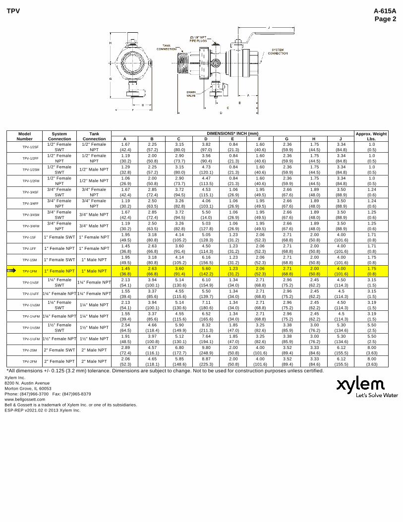
TPV A-615A Page 2
*All dimensions +/- 0.125 (3.2 mm) tolerance. Dimensions are subject to change. Not to be used for construction purposes unless certified.
Model Number
System Connection
Tank Connection
DIMENSIONS* INCH (mm) Approx. Weight Lbs.A B C D E F G H J
TPV-1/2SF1/2" Female
SWT1/2" Female
NPT 1.67
(42.4) 2.25
(57.2) 3.15
(80.0) 3.82
(97.0) 0.84
(21.3) 1.60
(40.6) 2.36
(59.9) 1.75
(44.5) 3.34
(84.8) 1.0
(0.5)
TPV-1/2FF1/2" Female
NPT1/2" Female
NPT 1.19
(30.2) 2.00
(50.8) 2.90
(73.7) 3.56
(90.4) 0.84
(21.3) 1.60
(40.6) 2.36
(59.9) 1.75
(44.5) 3.34
(84.8) 1.0
(0.5)
TPV-1/2SM1/2" Female
SWT1/2" Male NPT
1.29 (32.8)
2.25 (57.2)
3.15 (80.0)
4.73 (120.1)
0.84 (21.3)
1.60 (40.6)
2.36 (59.9)
1.75 (44.5)
3.34 (84.8)
1.0 (0.5)
TPV-1/2FM1/2" Female
NPT1/2" Male NPT
1.06 (26.9)
2.00 (50.8)
2.90 (73.7)
4.47 (113.5)
0.84 (21.3)
1.60 (40.6)
2.36 (59.9)
1.75 (44.5)
3.34 (84.8)
1.0 (0.5)
TPV-3/4SF3/4" Female
SWT3/4" Female
NPT 1.67
(42.4) 2.85
(72.4) 3.72
(94.5) 4.53
(115.1) 1.06
(26.9) 1.95
(49.5) 2.66
(67.6) 1.89
(48.0) 3.50
(88.9) 1.24 (0.6)
TPV-3/4FF3/4" Female
NPT3/4" Female
NPT 1.19
(30.2) 2.50
(63.5) 3.26
(82.8) 4.06
(103.1) 1.06
(26.9) 1.95
(49.5) 2.66
(67.6) 1.89
(48.0) 3.50
(88.9) 1.24 (0.6)
TPV-3/4SM3/4" Female
SWT3/4" Male NPT
1.67 (42.4)
2.85 (72.4)
3.72 (94.5)
5.50 (14.0)
1.06 (26.9)
1.95 (49.5)
2.66 (67.6)
1.89 (48.0)
3.50 (88.9)
1.25 (0.6)
TPV-3/4FM3/4" Female
NPT3/4" Male NPT
1.19 (30.2)
2.50 (63.5)
3.26 (82.8)
5.03 (127.8)
1.06 (26.9)
1.95 (49.5)
2.66 (67.6)
1.89 (48.0)
3.50 (88.9)
1.25 (0.6)
TPV-1SF 1" Female SWT 1" Female NPT 1.95
(49.5) 3.18
(80.8) 4.14
(105.2) 5.05
(128.3) 1.23
(31.2) 2.06
(52.3) 2.71
(68.8) 2.00
(50.8) 4.00
(101.6) 1.71 (0.8)
TPV-1FF 1" Female NPT 1" Female NPT 1.45
(36.8) 2.63
(66.8) 3.60
(91.4) 4.50
(114.3) 1.23
(31.2) 2.06
(52.3) 2.71
(68.8) 2.00
(50.8) 4.00
(101.6) 1.71 (0.8)
TPV-1SM 1" Female SWT 1" Male NPT 1.95
(49.5) 3.18
(80.8) 4.14
(105.2) 6.16
(156.5) 1.23
(31.2) 2.06
(52.3) 2.71
(68.8) 2.00
(50.8) 4.00
(101.6) 1.75 (0.8)
TPV-1FM 1" Female NPT 1" Male NPT 1.45
(36.8) 2.63
(66.8) 3.60
(91.4) 5.60
(142.2) 1.23
(31.2) 2.06
(52.3) 2.71
(68.8) 2.00
(50.8) 4.00
(101.6) 1.75 (0.8)
TPV-1¼SF1¼" Female
SWT1¼" Female NPT
2.13 (54.1)
3.94 (100.1)
5.14 (130.6)
6.10 (154.9)
1.34 (34.0)
2.71 (68.8)
2.96 (75.2)
2.45 (62.2)
4.50 (114.3)
3.15 (1.5)
TPV-1¼FF 1¼" Female NPT 1¼" Female NPT 1.55
(39.4) 3.37
(85.6) 4.55
(115.6) 5.50
(139.7) 1.34
(34.0) 2.71
(68.8) 2.96
(75.2) 2.45
(62.2) 4.5
(114.3) 3.15 (1.5)
TPV-1¼SM1¼" Female
SWT1¼" Male NPT
2.13 (54.1)
3.94 (100.1)
5.14 (130.6)
7.11 (180.6)
1.34 (34.0)
2.71 (68.8)
2.96 (75.2)
2.45 (62.2)
4.50 (114.3)
3.19 (1.5)
TPV-1¼FM 1¼" Female NPT 1¼" Male NPT 1.55
(39.4) 3.37
(85.6) 4.55
(115.6) 6.52
(165.6) 1.34
(34.0) 2.71
(68.8) 2.96
(75.2) 2.45
(62.2) 4.5
(114.3) 3.19 (1.5)
TPV-1½SM1½" Female
SWT1½" Male NPT
2.54 (64.5)
4.66 (118.4)
5.90 (149.9)
8.32 (211.3)
1.85 (47.0)
3.25 (82.6)
3.38 (85.9)
3.00 (76.2)
5.30 (134.6)
5.50 (2.5)
TPV-1½FM 1½" Female NPT 1½" Male NPT 1.91
(48.5) 3.97
(100.8) 5.12
(130.1) 7.64
(194.1) 1.85
(47.0) 3.25
(82.6) 3.38
(85.9) 3.00
(76.2) 5.30
(134.6) 5.50 (2.5)
TPV-2SM 2" Female SWT 2" Male NPT 2.89
(72.4) 4.57
(116.1) 6.80
(172.7) 9.80
(248.9) 2.00
(50.8) 4.00
(101.6) 3.52
(89.4) 3.33
(84.6) 6.12
(155.5) 8.00
(3.63)
TPV-2FM 2" Female NPT 2" Male NPT 2.06
(52.3) 4.65
(118.1) 5.85
(148.6) 8.87
(225.3) 2.00
(50.8) 4.00
(101.6) 3.52
(89.4) 3.33
(84.6) 6.12
(155.5) 8.00
(3.63)
Xylem Inc. 8200 N. Austin Avenue Morton Grove, IL 60053 Phone: (847)966-3700 Fax: (847)965-8379 www.bellgossett.com Bell & Gossett is a trademark of Xylem Inc. or one of its subsidiaries. ESP-REP v2021.02 © 2013 Xylem Inc.

Contact us for more information on the HYFAB MUA. 888.902.8324 www.hyfabco.com
HYFAB Makeup Assemblies (MUA’s)The design and installation of water make-up is critical to a closed-loop hydronic heating or cooling system. Incorrect pressurization may result in unwanted air which not only decreases comfort and efficiency but can also shorten the life of your system.
H Y F A B M A K E U P A S S E M B L I E S

HYFAB Makeup Assemblies (MUA’s)
HYFAB Make-up Assemblies are pre-engineered and factory built to ensure the make-up components are correctly assembled. These assemblies save time and money by reducing field labor costs.
• Reduces field labor cost by eliminating fabrication time• Pre-engineered for proper operation• Single source purchasing for all components • In stock for quick shipment• Meets Buy American Act (BAA)
Notes:1 Other pressures available by special order2 ¾" uses B&G 790 relief valve, 1" uses B&G 1170 relief valve3 RPZ and Double Check Backflow are by Apollo and same size as MUA
Item Number
Advantages
Contact us for information on how to save money with prefab MUA's. 888.902.8324 www.hyfabco.com0 7 / 2 0 1 3
M UA X X X - X - X X X - X X X - XMake-up
Assembly Size(Inch)
Relief Valve Size(Inch)
Relief Valve Setting(PSI)2
PRVPressure Range (PSI)1
Backflow Preventer3
075 – 3/4"
100 – 1"
075 – 3/4"
100 – 1"
L - 10 to 25H - 25 to 60
N - 15 – 75
N - NoneR - RPZ with Air GapD - Double Check
*Only available with 3/4" Relief Valve Selection
015*030036045050075100125

Model Number
Input MBHThermal
%
Gross Output MBH
NetAHRI Rating MBH
Turn-down A B C D E F G H J K L M N O P Q R Gas
Conn.
WaterAir
IntakeVent Size
Oper. Weight(with
water)
Ship. Weight(lbs.)Min Max Inlet/
Outlet
FB*0751 50 750 96.2% 722 628 15:1 78” 30” 55-1/2” 57-5/8” 66-1/8” 11-7/8” 11-3/8” 11-1/4” 12-1/2” 55” 51” 13” 8-3/4” 26-3/4” 23-3/4” 49-1/2” 7-3/8” 1-1/4” 3” 6” 6” 1,768 1,560FB*1001 50 999 96.2% 961 836 20:1 78” 30” 56-1/2” 57-5/8” 66-1/8” 11-7/8” 11-3/8” 11-1/4” 12-1/2” 56” 51” 13” 8-3/4” 26-3/4” 23-1/8” 49-1/2” 6-1/2” 1-1/4” 3” 6” 6” 1,838 1,596FB*1251 62.5 1,250 96.2% 1,203 1,046 20:1 78” 30” 56-1/2” 57-3/4” 66-1/8” 11-7/8” 11-3/8” 11-1/4” 12-1/2” 56” 51-3/8” 13” 8-3/4” 26-3/4” 21-5/8” 49-1/2” 6-1/2” 1-1/2” 3” 6” 8” 1,975 1,648FB*1501 60 1,500 96.2% 1,443 1,255 25:1 78” 30” 67-3/4” 68” 65-3/8” 12-3/8” 11-3/8” 11-1/4” 12-1/2” 67-1/4” 62-3/8” 15-7/8” 9” 26-7/8” 27-7/8” 59-1/4” 5-1/8” 1-1/2” 4” 8” 8” 2,307 1,961FB*1751 70 1,750 96.2% 1,684 1,464 25:1 78” 30” 66-1/4” 68” 65-3/8” 12-3/8” 11-3/8” 11-1/4” 12-1/2” 65-3/4” 61-1/2” 15-7/8” 9” 27” 27-1/8” 58-3/4” 5-1/8” 1-1/2” 4” 8” 8” 2,458 2,017FB*2001 80 1,999 96.2% 1,923 1,672 25:1 78” 30” 66-1/2” 68” 65-3/8” 12-3/8” 11-3/8” 11-1/4” 12-1/2” 66” 61-1/2” 15-7/8” 9” 27” 26-3/4” 58-3/4” 5-1/8” 1-1/2” 4” 8” 8” 2,570 2,087FB*2501 125 2,500 96% 2,400 2,087 20:1 77-3/4” 35” 83-3/4” 83-3/4” 63-3/4” 13-1/2” 11-1/4” 10-1/2” 12-1/4” 83-1/4” 76-1/4” 19-3/4” 9-1/4” 28-3/4” 32” 71” 7-1/4” 2” 4” 8” 9” 3,600 2,577FB*3001 150 3,000 96% 2,883 2,507 20:1 77-3/4” 35” 83-3/4” 83-3/4” 63-3/4” 13-1/2” 11-1/4” 10-1/2” 12-1/4” 83-1/4” 76-1/4” 19-3/4” 9-1/4” 28-3/4” 32” 71” 7-1/4” 2” 4” 10” 10” 3,900 2,881FB*3501 175 3,500 96% 3,364 2,925 20:1 77-3/4” 42” 91-1/2” 86-3/4” 63-1/2” 13-1/4” 11-1/2” 10-3/4” 12-1/2” 91” 82” 20-1/4” 12-3/4” 35-1/2” 31-3/4” 73-1/4” 8-3/4” 2” 4” 10” 10” 4,600 3,218FB*4001 333.3 3,999 96% 3,843 3,342 12:1 77-3/4” 45-1/2” 103-1/2” 99” 63-1/2” 13-3/4” 11-1/2” 10-3/4” 12-1/2” 103” 94” 24-3/4” 13-1/2” 39-1/2” 42-1/4” 85-1/4” 10-1/2” 2-1/2” 4” 12” 12” 5,200 3,805FB*5001 499.9 4,999 96% 4,804 4,177 10:1 77-3/4” 46-1/2” 102-1/4” 99-1/2” 63-1/2” 15” 11-1/2” 10-3/4” 12-1/2” 101-3/4” 92-1/2” 22” 14” 39-3/4” 39-1/2” 84” 9” 2-1/2” 6” 14” 14” 5,900 4,101FB*6001 600 6,000 96% 5,766 5,014 10:1 77-3/4” 50” 102-3/4” 99-3/4” 63-1/4” 14-3/4” 11-1/2” 10-3/4” 12-1/2” 102-1/2” 93-1/4” 20” 15-3/4” 43-1/2” 36-1/2” 83-3/4” 9-1/4” 3” 6” 14” 14” 6,900 4,711
MODELS FB 0751 - FB 6001
CRESTCOMMERCIAL
CONDENSING BOILERSubmittal Sheet FBN-Sub-13
JOB NOTES:
G F
E
J
AK
L
MP
Q
R
CD
H
B
NO
Water IN
Flue Vent
AirInlet
GasConnection
Clean-OutDrain
Water OUT
Job Name: Location:
_______________________________________________ _______________________________________________
Engineer: Model #:
_______________________________________________ _______________________________________________
Contractor: Type Gas:
_______________________________________________ _______________________________________________
Agent/Wholesaler: Equipment Tag(s):
_______________________________________________ _______________________________________________
SIDE BACK TOP
Notes:* Insert “N” for natural gas, “L” for LP gas models and
“D” for dual fuel.• Indoor installation only. • Low NOx Operation.• Lochinvar should be consulted before selecting a boiler
for installations having unusual piping and pickup requirements, such as intermittent system operation, extensive piping systems, etc.
• The ratings have been determined under the provisions governing forced draft burners.
• The Net AHRI water ratings shown are based on a piping and pickup allowance of 1.15.
Information subject to change without notice. Dimensions shown are approximate and should not be used for construction purposes.

Smart Touch™ FeaturesCON·X·US Remote Connect
SMART TOUCH Touchscreen Operating Control
Full-Color 8” Touchscreen LCD Display
Built-in Cascading Sequencer for up to 8 Boilers > Built-in Redundancy > Cascade Multiple Sized Boilers > Lead/Lag Cascade > Efficiency Optimized Cascade
Front-End Loading Capability with Copper-Fin II® and Power-Fin® Boilers
Building Management System Integration with 0-10 VDC Input
BACnet MSTP Communications
Outdoor Reset Control with Outdoor Air Sensor
Password Security
Domestic Hot Water Prioritization > DHW tank piped with priority in the boiler loop > DHW tank piped as a zone in the system with the
pumps controlled by the Smart System > DHW Modulation Limiting > Separately Adjustable SH/DHW Switching Times
Low Water Flow Safety Control & Indication
Inlet & Outlet Temperature Readout
Freeze Protection
Service Reminder
Time Clock
Data Logging > Hours Running, Space Heating > Hours Running, Domestic Hot Water > Hours Running, Modulation Rate > Ignition Attempts > Last 10 Lockouts
Programmable System Efficiency Optimizers > Night Setback > Anti-Cycling > Outdoor Air Reset Curve > Ramp Delay > Boost Temperature & Time > Modulation Factor Control
Three Pump Control > System Pump > Boiler Pump > Domestic Hot Water Pump
07/20—Printed in U.S.A.
Lochinvar, LLC 300 Maddox Simpson ParkwayLebanon, Tennessee 37090P: 615.889.8900 / F: 615.547.1000
Lochinvar.com
Codes & Registrations ANSI Z21.13/CSA Certified
ASME Certified, “H” Stamp / National Board
California Code Compliant
Canadian Registration Number (CRN)
CSD1 / Factory Mutual / GE Gap Compliant
South Coast Air Quality Management District Qualified & Energy Star Rated (FB 0751-2001)
High-Voltage Terminal Strip > 120V/1PH/60Hz Power Supply (FB 0751-2001) > 208V/3PH/60Hz Power Supply (FB 2501-3501) > 480V/3PH/60Hz Power Supply (FB 4001-6001) > System Pump, Boiler Pump and DHW Pump Power
Low-Voltage Terminal Strip > 24 VAC Auxiliary Device Relay > Auxiliary Proving Switch Contacts > Alarm on Any Failure Contacts > Runtime Contacts > DHW Thermostat Contacts > Unit Enable/Disable Contacts > System Sensor Contacts > DHW Tank Sensor Contacts > Outdoor Air Sensor Contacts > Cascade Contacts > 0-10 VDC BMS External Control Contact > 0-10 VDC Variable Speed Boiler Pump Control Contact
Standard FeaturesProof of Closure Valve (FB 6001)
Modulating Burner with up to 25:1 Turndown
Direct-Spark Ignition
Low NOx Operation
Sealed Combustion
Air Inlet Filter
Low Gas Pressure Operation
Vertical and Horizontal Direct Venting > Direct Vent up to 100 Feet > PVC, CPVC, Polypropylene or AL29-4C
(FB 0751-4001) > AL29-4C (FB 0751-6001)
ASME “H” Stamped Heat Exchanger
316L Stainless Steel Fire Tubes
160 psi Working Pressure
On/Off Switch
Adjustable High Limit with Manual Reset
Low Water Cutoff with Manual Reset & Test
High & Low Gas Pressure Switches w/Manual Reset
Low Air Pressure Switches
Condensate Trap w/Blocked Drain Switch
Drain Valve
System Sensor
Outdoor Air Sensor
Inlet & Outlet Temperature Sensors
High-Voltage Terminal Strip
Low-Voltage Terminal Strip
Downstream Gas Test Cocks
50 psi ASME Relief Valve
Temperature & Pressure Gauge
Zero Clearances to Combustible Materials
High Altitude Models Available
10-Year Limited Warranty (See Warranty for Details)
1-Year Warranty on Parts (See Warranty for Details)
Optional EquipmentAlarm on Any Failure
ASME Relief Valve Option:75 psi 100 psi 125 psi 150 psi
BMS Gateway - BACnet IP or LonWorks
Condensate Neutralization Kit
Common Vent Kits Damper
Modbus Communication
Motorized Isolation Valve
RealTime O2 Feedback™
Variable Speed Boiler Pump
Wireless Outdoor Temperature Sensor
Electrical Transformer Options (Shipped Loose):> FB 0751-2001
208V/3PH/60Hz g 120V/1PH/60Hz
480V/3PH/60Hz g 120V/1PH/60Hz
600V/3PH/60Hz g 120V/1PH/60Hz
> FB 2501-3501
480V/3PH/60Hz g 208V/3PH/60Hz
600V/3PH/60Hz g 208V/3PH/60Hz
> FB 4001-6001
208V/3PH/60Hz g480V/3PH/60Hz
600V/3PH/60Hz g 480V/3PH/60Hz
C E R T I F I E D
0751-2001

SAP Magna 3 Volt Max Pipe A B C D E Part No. Model Amps Size
VARIABLE SPEED PUMP
Submittal Sheet VSP-Sub-05
Job Name: __________________________________
Location: __________________________________
Engineer: __________________________________
Agent/Wholesaler: ______________________________
Contractor: __________________________________
NOTES:
Model No. __________________________________
Equipment Tag(s):
_____________________________________________
_____________________________________________
VARIABLE SPEED PUMP
3/21—Printed in U.S.A.
Lochinvar, LLC 300 Maddox Simpson ParkwayLebanon, Tennessee 37090P: 615.889.8900 / F: 615.547.1000
Lochinvar.com
STANDARD FEATURES• Digital Display
• Composite Rotor Can
• 316 L Stainless Steel Shaft
• Composite Impeller
• Cast Iron Housing
• Pump Status Indicator
• Alarm Contacts
A
C D B
E
100208411 40-80 115 VAC 2.5 1-1/2” 8-1/2” 14-3/4” 4-1/4” 6-1/2” 12”
100208412 50-150 115 VAC 5.6 2” 11” 15-3/4” 5” 6-1/2” 12”
100277760 80-100 208/230 VAC 1PH 4.6 3” 14-1/4” 17” 6-1/2” 6-1/2” 12-1/2”
100327104 100-120 208/230 VAC 1PH 7.0 4” 17-3/4” 17-3/4” 7” 6-1/2” 13”

GAS REGULATOR
Submittal Sheet BGR-Sub-04
Job Name: __________________________________
Location: __________________________________
Engineer: __________________________________
Agent/Wholesaler: ______________________________
Contractor: __________________________________
NOTES:
Model No. __________________________________
Equipment Tag(s):
_____________________________________________
_____________________________________________
Standard Features
• ANSI Z21.80A-2019 / CSA 6.22A-2019 Class I Certified for outlet pressures up to 14”
• Integral vent limiter
• CSA approved External Vent Limiter – no vent line required*
• 500:1 Turndown
• Positive 100% bubble tight lock up regulator
• Suitable for NG and LP
• Suitable for indoor or outdoor installation
• Up to 2 PSIG and 10 PSIG inlet pressures available
• 10 PSIG inlet models are Over Pressure Device (OPD), Worker & Monitor style
3/21—Printed in U.S.A.
Lochinvar, LLC 300 Maddox Simpson ParkwayLebanon, Tennessee 37090P: 615.889.8900 / F: 615.547.1000
Lochinvar.com
SAP Inlet Pressure Outlet Pressure Unit Gas (Threaded) (Flanged) Ship Wgt. Number Rating Rating Conn. Size A B C D E (lbs.) 100269922 3” W.C. to 2 PSIG 2” W.C. to 14” W.C. 1-1/4” 7-3/4” – 1-1/4” NPT 10” – 8
100269923 3” W.C. to 2 PSIG 2” W.C. to 14” W.C. 1-1/2” 7-3/4” – 1-1/2” NPT 10” – 8
100269924 3” W.C. to 2 PSIG 2” W.C. to 14” W.C. 2” 9-1/4” – 2” NPT 12-1/2” – 13
100269925 3” W.C. to 2 PSIG 2” W.C. to 14” W.C. 2-1/2” – 17” 2-1/2” Flanged – 17-1/4” 28
100320057 3” W.C. to 2 PSIG 2” W.C. to 14” W.C. 3” – 17” 3” Flanged – 16-3/4” 28
100320058 7” W.C. to 10 PSIG 2” W.C. to 14” W.C. 1-1/4” 16-3/4” – 1-1/4” NPT 9-1/2” – 16
100320059 7” W.C. to 10 PSIG 2” W.C. to 14” W.C. 1-1/2” 16-3/4” – 1-1/2” NPT 9-1/2” – 16
100320060 7” W.C. to 10 PSIG 2” W.C. to 14” W.C. 2” 20” – 2” NPT 12” – 25
100320061 7” W.C. to 10 PSIG 2” W.C. to 14” W.C. 2-1/2” – 34” 2-1/2” Flanged – 16-3/4” 56
100320062 7” W.C. to 10 PSIG 2” W.C. to 14” W.C. 3” – 34” 3” Flanged – 16-3/4” 56
* Brass Vent Limiters must be removed for outdoor installation.
BA
DE
C C