jieo technical report 8249 - jitc - homepagejitc.fhu.disa.mil/tssi/docs/gscr_97.pdf · jieo...
TRANSCRIPT

JIEO Technical Report 8249
Defense Information System NetworkCircuit Switched Subsystem
Defense Switched Network (DSN)Generic Switching Center Requirements
(GSCR)
March 1997
PROJECT OFFICER APPROVED FOR PUBLICATION
Wing C. Quan Warren P. Hawrylko
FOREWORD
The Joint Interoperability and Engineering Organization (JIEO), Center forSystems Engineering (CFSE) publishes Technical Reports to provideengineering guidance to Department of Defense Departments/Agencies, andtheir contractors engaged in engineering, RDT&E, procurement, installation,testing, acceptance, and O&M of specific Defense Information Systems.Before using this document as, or a part of procurement specifications,coordination should be accomplished with CFSE or the cognizant DISA ProgramOffice to ensure currency and propriety of the application.
Comments or technical inquires concerning this document are welcome, andshould be directed to:
Deputy CommanderJoint Interoperability and Engineering OrganizationCenter for System Engineering10701 Parkridge BoulevardReston, Virginia 20191-4357

JIEO Technical Report 8249iii
Table of Contents
Section Page
Foreword i
Errata Sheet xviii
1 Introduction 11.1 Applicability 11.2 Authority 11.3 References 11.4 DISN Architecture 31.5 GSCR Scope 4
1.5.1 DSN Architecture 41.6 Switching Elements 5
1.6.1 Tandem Switch 51.6.2 End Office Switch 5
1.6.2.1 Private Branch Exchange 51.6.3 Multifunction Switch 6
1.7 DSN Lines and Trunks 61.7.1 DSN Lines 61.7.2 DSN Trunks 7
1.7.2.1 Access Trunks 71.7.2.2 DSN Interswitch Trunks (ISTs) 81.7.2.3 Gateway Trunks. 8
1.8 Connectivity to Subsystems 91.9 Description of GSCR 9
1.9.1 Relationship to Bellcore Commercial Requirements 91.9.2 Description of LSSGR 101.9.3 Relationship to Commercial Standards 10
2 Capabilities and Features 112.1 Capabilities and Features Descriptions 11
2.1.1 Residence and Business Customer Station Features 112.1.2 Facility Access and Services 152.1.3 Attendant Features 17
2.1.3.1 Precedence and Preemption 182.1.3.2 Call Display 182.1.3.3 Class of Service Override 182.1.3.4 Busy Override and Busy Verification 182.1.3.5 Interposition Calling 192.1.3.6 Interposition Transfer 192.1.3.7 Call Extension 192.1.3.8 Call Hold 19
Section Page
JIEO Technical Report 8249iv
2.1.3.9 Two-Party Hold on Console 192.1.3.10 Unattended Console 192.1.3.11 Audible Call Indicators 192.1.3.12 Automatic Recall of Attendant 20
2.1.4 Customer Access Interfaces 202.1.5 Public Safety Features 202.1.6 Miscellaneous Switch Capabilities and Features 212.1.7 Interoffice Features 222.1.8 Call Processing Features 242.1.9 Database Services 252.1.10 System Maintenance Features 262.1.11 Trunk, Line, Special Service Circuit Test Features 272.1.12 Administrative Features 292.1.13 Reliability Features 312.1.14 Cutover and Growth Features 322.1.15 Billing and Comptroller Features 32
2.2 Military Unique Features (MUF) 332.2.1 Multi-Level Precedence and Preemption (MLPP) 33
2.2.1.1 Description 342.2.1.2 Procedures 352.2.1.3 Exceptional Procedures 36
2.2.2 Community of Interest (COI) 372.2.2.1 General Treatment 372.2.2.2 Precedence Treatment 37
2.2.3 Preset Conferencing 382.2.3.1 Conference Notification Recorded
Announcement 392.2.3.2 Conference Precedence Level 402.2.3.3 Automatic Retrial and Alternate Address 402.2.3.4 Bridge Release 412.2.3.5 Lost Connection to Conferee or
Originator 412.2.3.6 Secondary Conferencing 412.2.3.7 Address Translation 42
2.2.4 Nailed-Up Connections 422.2.5 Common Channel Signaling System No. 7 (CCS7) 432.2.6 DSN Worldwide Routing and Numbering Plan 44
2.3 Advanced Intelligent Network (AIN) 44
3 Subscriber Access 45
4 Reserved for Future Use 47
5 Call Processing 495.1 General 49
5.1.1 Relationship to the LSSGR. 49
Section Page
JIEO Technical Report 8249v
5.2 Call Treatments 495.2.1 Origination Treatment. 49
5.2.1.1 Originating Busy 505.2.2 Termination Treatment 50
5.2.2.1 Busy or Idle Status 505.2.2.2 Ringing Signals 505.2.2.3 Intercept Facilities 505.2.2.4 Announcing Equipment 50
5.2.3 Release Treatment 515.2.4 Interruption Treatment 51
5.3 Internal Call Processing Functions 515.3.1 Connections 515.3.2 Class of Service 51
5.3.2.1 Customer Classes of Service 515.3.2.2 Trunk Classes of Service 52
5.3.3 Code Interpretation 525.3.3.1 Customer-Dialed Codes 525.3.3.2 Intersystem Codes 565.3.3.3 Operator Services Feature Interactions 56
5.3.4 Screening 575.3.4.1 Community of Interest 575.3.4.2 Zone Restriction Servicing of Local
Originators 575.3.4.3 DSN Access Restriction 585.3.4.4 Precedence Signaling. 585.3.4.5 Private Branch Exchange (PBX) Access
Line Preemption 595.3.4.6 MLPP Interworking With Other Networks 595.3.4.7 MLPP Interaction With Other Services 605.3.4.8 Attendant Calls 635.3.4.9 Precedence Calls to a Remote Office 63
5.3.5 Routing 645.3.5.1 Outgoing Calls 645.3.5.2 Corridor Calls 645.3.5.3 Primary and alternate Routes 64
5.3.6 Outpulsing Code Formulation 655.3.7 Trunk Selection (Hunting) 65
5.3.7.1 Hunt Sequence for Classmarked Trunks 655.3.8 Internal Overload Control 685.3.9 Essential Service Protection (ESP) 685.3.10 Automatic Message Accounting (AMA) 68
5.4 Switch Processing Time 685.5 DSN Worldwide Routing and Numbering Plan 68
5.5.1 General 68

Section Page
JIEO Technical Report 8249vi
5.5.2 Standard Directory Numbers 685.5.3 Standard Test Numbers 695.5.4 Switch Code Assignments 695.5.5 Base Services - Abbreviated Numbers 69
5.6 DSN Announcements 70
6 Signaling 736.1 General 73
6.1.1 Battery Supplies and Internal Resistance 736.2 Customer Line Signaling 736.3 In-Band Signaling 73
6.3.1 Preempt Signaling 736.4 Control Signaling 746.5 Common Channel Signaling Number 7 74
6.5.1 Overview 746.5.1.1 CCS7 Network Structure. 766.5.1.2 CCS7 Network Access 776.5.1.3 DSNSS7 Protocol 796.5.1.4 Multiple Point Code Capability 796.5.1.5 Numbering of Signaling Point Codes 79
6.5.2 Signaling Link Characteristics. 796.5.2.1 Error Detection and Recovery 79
6.5.3 Message Signal Unit Information Handling 796.5.3.1 Routing Label 79
6.5.4 Signaling Network Management 806.5.4.1 Signaling Link Changeback 806.5.4.2 Signaling Network Congestion 80
6.5.5 Noncircuit-Related Information Exchange - SignalingConnection Control Part (SCCP) 80
6.5.6 Additional Procedures for Switch-to-Switch/SCP TCAPMessages 816.5.6.1 Transaction Capability Application Part
(TCAP) - Definitions and Functions ofTransaction Capability (TC) Operations,Parameters, and Error Codes. 81
6.5.7 Circuit-Related Information Exchange 816.5.8 Switch Capacity 816.5.9 Performance 816.5.10 CCS7 Message Formatting 81
6.5.10.1 Message Signaling Unit (MSU) ServiceInformation. 82
6.5.11 CCS7 ISDN User Part (IS-UP) 826.5.11.1 IS-UP Messages 826.5.11.2 IS-UP Parameters 83

Section Page
JIEO Technical Report 8249vii
6.6 DSN ISDN User to Network Signaling. 836.6.1 Application 846.6.2 Related Specifications 846.6.3 Compatibility 846.6.4 Physical Layer. 85
6.6.4.1 S/T Reference Point 856.6.4.2 Line Code 85
6.6.5 Data-Link Layer. 866.6.5.1 Data-Link Connections 866.6.5.2 Peer-to-Peer Procedures of the Data-Link
Layer 866.6.6 Layer 3 DSN User-to-Network Signaling 86
6.6.6.1 Layer 3 - Overview of Layer 3. 876.6.6.2 DSN User-to-Network Signaling for
Circuit-Switched (CS) Bearer Service 876.6.6.3 Supplementary Services. 91
7 Transmission 937.1 General 93
7.1.1 Requirements Terminology 937.2 Transmission Performance 937.3 Transmission Loss Plans 937.4 Loss Plan Implementation 937.5 Switching System Interfaces and Connections 947.6 Transmission Measurement Techniques 947.7 Performance Requirements 94
7.7.1 General 947.7.2 Loss and Variability 947.7.3 Attenuation Distortion 947.7.4 Noise 957.7.5 Input Impedance 957.7.6 Envelope Delay Distortion 957.7.7 Linearity 957.7.8 Single Frequency Distortion 967.7.9 Echo Path Delay 967.7.10 Talker and Listener Echo Control 967.7.11 Longitudinal Balance 967.7.12 Crosstalk 967.7.13 Digital Impairments 967.7.14 Conference Bridging Facilities 96
8 Automatic Message Accounting (AMA) 978.1 Introduction 978.2 AMA Requirements 97
8.2.1 Settable BAF Fields 97

Section Page
JIEO Technical Report 8249viii
8.2.2 Minimum Retention Time 978.2.3 Removable Hardcopy Recording 98
9 Measurements and Administration 1019.1 Introduction 1019.2 Traffic Management 101
9.2.2.1 DSN Unique Measurements 1019.3 Service Measurements 1039.4 Service Evaluation 1039.5 Database Management 1039.6 Generic Program Alteration 104
10 System Interfaces 10510.1 Analog Interface. 105
10.1.1 Trunk and Gateway Trunk Circuits 10510.1.1.1 Compatibility 10510.1.1.2 Directionalization 10510.1.1.3 Electrical Characteristics 10510.1.1.4 Signaling 10510.1.1.5 European Interfaces 105
10.1.2 Operator, Directory Assistance, and Intercept Systems. 10610.1.3 Access Line Interface 106
10.2 Digital Interfaces. 10610.2.1 Encoding 10610.2.2 Digital Line Interface 106
10.2.2.1 Non-Basic Rate Interface (BRI) Lines 10610.2.2.2 BRI Lines 107
10.2.3 Trunk and Access Line Combinations 10710.3 Support System Interface Protocol 10710.4 Switch Cross-Connection Systems 10710.5 Commercial Access Lines 10710.6 Tactical Interface 10810.7 DRSN Interface 10810.8 North Atlantic Treaty Organization (NATO) Initial Voice Switched
Network (IVSN) Interface 10810.9 Release Link Trunks (RLTs) 10810.10 Synchronous Optical Network (SONET) Interface 10810.11 Synchronization 109
10.11.1 Timing Modes 10910.11.2 Internal Clock Requirements. 109
10.11.2.1 Fast (Acquisition) Mode 10910.11.2.2 Normal (Tracking Mode) 11010.11.2.3 Initial Clock Configuration 110
Section Page
JIEO Technical Report 8249ix
10.11.2.4 External Reference Source Switchover 11010.11.3 Synchronization Performance Criteria 110
10.11.3.1 Synchronization During AbnormalOperating Conditions 110
10.11.3.2 Satellite Transmission 11110.12 Integrated Digital Loop Carrier (IDLC) 111
11 Service Standards 11311.1 General 11311.2 Busy Hour Criteria 113
11.2.1 Traffic Load 11311.2.2 Definitions 11311.2.3 Busy Hour Service Standards 113
11.2.3.1 Grade of Service 11411.2.3.2 Access to Recorded Announcements 11411.2.3.3 Trunk Tandem Delay. 114
11.3 Non-Traffic Sensitive Criteria 115
12 Reliability 11712.1 Introduction 11712.2 Application of Reliability Criteria 11712.3 Hardware Reliability Modeling Methods 11712.4 Hardware Reliability Parameters 11712.5 Hardware Reliability Requirements 11712.6 Application of Field Performance Requirements 11712.7 Outage Reporting and Analysis 11812.8 Definitions of Switch Degradation 11812.9 System Level Measures and Requirements. 11812.10 Individual Termination Requirements 11812.11 Other Reliability Criteria 118
13 Power 11913.1 Introduction 11913.2 LSSGR Contents 11913.3 Requirements 120
13.3.1 Battery Reserve Time 120
14 Network Equipment-Building System (NEBS) Requirements: PhysicalProtection 12314.1 Introduction 12314.2 Structure of LSSGR Section 14 123

Section Page
JIEO Technical Report 8249x
15 Electromagnetic Compatibility and Electrical Safety 12515.1 Introduction 12515.2 Requirements 125
16 Network Traffic Management 12716.1 Introduction 12716.2 Scope of Network Traffic Management (NTM) Requirements 127
16.2.1 Integrated NTM Strategy 12716.2.2 NTM Capabilities Guidelines. 127
16.3 Common Data Requirements 12716.4 NTM Surveillance Data 128
16.4.1. Circuit Switch Measurements 12816.4.1.1 Basic Switch 12816.4.1.2 Line Servicing 12816.4.1.3 Trunk Groups 128
16.4.2 Switch Services 12816.4.3 Common Channel Signaling Network 12916.4.4 Number Services 12916.4.5 ISDN 12916.4.6 Public Packet Switched Network (PPSN) 12916.4.7 Alternate Billing Service (ABS) 12916.4.8 Switched Multi-Megabit Data Service (SMDS) 12916.4.9 Switched Fractional DS1 Service (SWF-DS1) 130
16.5 NTM Automatic Controls 13016.5.1 Description of NTM Automatic Controls 13016.5.2 User Perspective 13016.5.3 Circuit Switch Requirements 130
16.5.3.1 Automatic Congestion Controls (ACC) 13016.5.3.2 Automatic Call Gap (ACG) 13116.5.3.3 Trunk Reservation (TR) 13116.5.3.4 Selective Incoming Load Control 13116.5.3.5 Media Stimulated Mass Calling (MSMC) 13116.5.3.6 Dynamic Overload Control (DOC) 13116.5.3.7 Automatic Operation with Hard To Reach
(HTR) Codes 13216.5.4 Common Channel Signaling Network 13216.5.5 Number Services. 13216.5.6 ISDN 13216.5.7 PPSN 13216.5.8 ABS 13216.5.9 SMDS 13216.5.10 Switched Fractional DS1 Service 133
16.6 NTM Manual Controls 13316.6.1 Description of NTM Manual Controls 13316.6.2 User Perspective 133

Section Page
JIEO Technical Report 8249xi
16.6.3 Circuit Switch Requirements. 13316.6.3.1 Code Controls 13316.6.3.2 Trunk Group Controls 13316.6.3.3 Code Classification 134
16.6.4 CCS 13416.6.5 Number Services. 13416.6.6 ISDN 13416.6.7 PPSN 13416.6.8 ABS 13416.6.9 SMDS 13416.6.10 Switched Fractional DS1 Service 135
16.7 NTM OS/NE Interfaces 135
17 Traffic Capacity and Environment 13717.1 Introduction 13717.2 LSSGR Contents 13717.3 Traffic Capacity Requirements 138
18 Network Element and Network System Security 13918.1 Introduction 13918.2 Rationale for NE/NS Security Measures 13918.3 Security Feature Requirements 140
18.3.1 Overview 14018.3.2 Identification 14018.3.3 Authentication 14018.3.4 System Access Control 14118.3.5 Resource Access Control 14118.3.6 Security Log (Audit) 14118.3.7 Data and System Integrity 14118.3.8 Security Administration 141
18.4 Development Life Cycle Requirements 141
19 Documentation 14319.1 General 14319.2 Supplier Documentation and Translation Guide 14319.3 Supplier Support Generic Requirements 14319.4 Documentation Standards 144
20 Tandem Switching 14520.1 Introduction 14520.2 Network Plan 14520.3 System Architecture 14520.4 Tandem Switching Features and Functions 14520.5 Call Processing 150
Section Page
JIEO Technical Report 8249xii
20.6 Signaling 15020.7 Transmission 15020.8 Automatic Message Accounting 15020.9 Switching System Maintenance 15120.10 System Interfaces 15120.11 Service Standards 15120.12 Reliability 15120.13 Power 15120.14 Equipment 15220.15 Electromagnetic and Electrical Environment 15220.16 Network Management 15220.17 System Capacity 15220.18 Synchronization 15220.19 Documentation 152
21 Integrated Services Digital Network Generic Requirements 15321.1 Introduction 15321.2 DSN Generic ISDN Features and Interface Descriptions 15321.3 ISDN Supplementary Services 163
21.3.1 Multilevel Precedence and Preemption 16321.3.2 Conference Calling 16321.3.3 User-to-User Signaling 16321.3.4 Call Hold 16321.3.5 Call Waiting 16321.3.6 Normal Call Transfer 16421.3.7 Explicit Call Transfer 16421.3.8 Call Deflection 16421.3.9 Community of Interest (COI) 16421.3.10 Hotline Service 164
21.3.10.1 Protected Hotline Calling 16521.3.10.2 Pair Protected Hotline Calling 16521.3.10.3 Unprotected Hotline Calling 16621.3.10.4 Protected Hotline Receiving 166
21.3.11 Preset Conference Calling 16621.3.11.1 Proceedures 16621.3.11.2 Managing Individual Conferences. 16821.3.11.3 Conferee Actions 16921.3.11.4 Interworking Considerations 17021.3.11.5 Capabilities for Charging 17021.3.11.6 Interaction With Other Supplementary
Services 17021.3.11.7 Functional Capabilities and
Information Flows 170

Section Page
JIEO Technical Report 8249xiii
21.3.11.8 Switching and SignalingSpecification 170
21.3.11.9 Switching and Signaling AtInterexchange Interfaces. 170
21.3.11.10 Protocol Interworking 170
Glossary 173

JIEO Technical Report 8249xiv
List of Figures
Figure Page
1-1 DSN Network Elements 7
5-1 Hunt Sequence for Classmarked ISTs 66
6-1 DSN Preempt Signaling 77
6-2 CCS7 Backbone Network Architecture 78

JIEO Technical Report 8249xv
List of Tables
Table Page
2-1 Residence and Business Customer Station Features 12
2-2 Facility Access and Services 15
2-3 Attendant Features 17
2-4 Customer Access Features 20
2-5 Public Safety Features 21
2-6 Miscellaneous Switch Capabilities and Features 21
2-7 Interoffice Features 22
2-8 Call Processing Features 24
2-9 Database Services 26
2-10 System Maintenance Features 26
2-11 Trunk, Line, Special Service Circuit Test 28
2-12 Administrative Features 30
2-13 Reliability Features 32
2-14 Cutover and Growth Features 32
2-15 Billing and Comptroller Features 33
2-16 Precedence Levels 34
5-1 DSN User Dialing Format 54
5-2. Precedence And Service Access Codes 55
5-3 Route Code Assignment 56
5-4 DSN Switch Outpulsing 57
5-5 Standard Directory Numbers 69
5-6 Standard Test Numbers 70
5-7 DSN Announcements 71

Table Page
JIEO Technical Report 8249xvi
6-1 DISN Information Signals for EO and PBX 76
6-2 Service Indicator Codes 83
6-3 Setup Message For MLPP Call 89
7-1 Input Impedance (≥ 2 dB loss) 95
8-1 DSN AMA Settable Fields 99
11-1 DSN Grade-of-Service Objectives 114
20-1 Tandem Features 146
21-1 BRI Access, Call Control, and Signaling 154
21-2 Uniform Interface Configurations for BRIs 154
21-3 BRI Features 155
21-4 PRI Access, Call Control, and Signaling 160
21-5 PRI Features 160
21-6 Packet Data Features and Capabilities 161
21-7 Operations Capabilities 162
21-8 Cross Platform Capabilities 162
21-9 Preset Conference Subscription Options 167

JIEO Technical Report 8249
1
JIEO Technical Report 8249Errata Sheet - August 1997
Defense Switched Network (DSN) Generic Switching Center Requirements (GSCR)
1. Section 2, Page 12, Table 2-1.Change Feature Number 01-02-0100 as follows:
FEATURE NO TITLE REFERENCE01-02-0100 Individual Line FSD 01-02-0100
2. Section 5, Page 55, Table 5-2. The Service Digit “5” is assigned for “Off-net 700 services”.
3. Section 5, Page 70, Table 5-6. Add to the “Number Assignment: KNX-1081” for “Call Type: Digital Loop Back Testing”.
4. Section 6, Page 76, Table 6-1.Change entry for Audible Ringback Precedence Call as follows:
Signal Frequency(Hz)
Single ToneLevel
CompositeLevel
InterruptRate
Tone On Tone Off
Audible RingbackPrecedence Call
440 + 480(Mixed)
-19 dBm0 -16 dBm0 30 Impulsesper Minute(IPM)
1640 ms 360 ms
Preemption Tone 440+620(Mixed)
-19 dBm0 -16 dBm0 Steady On
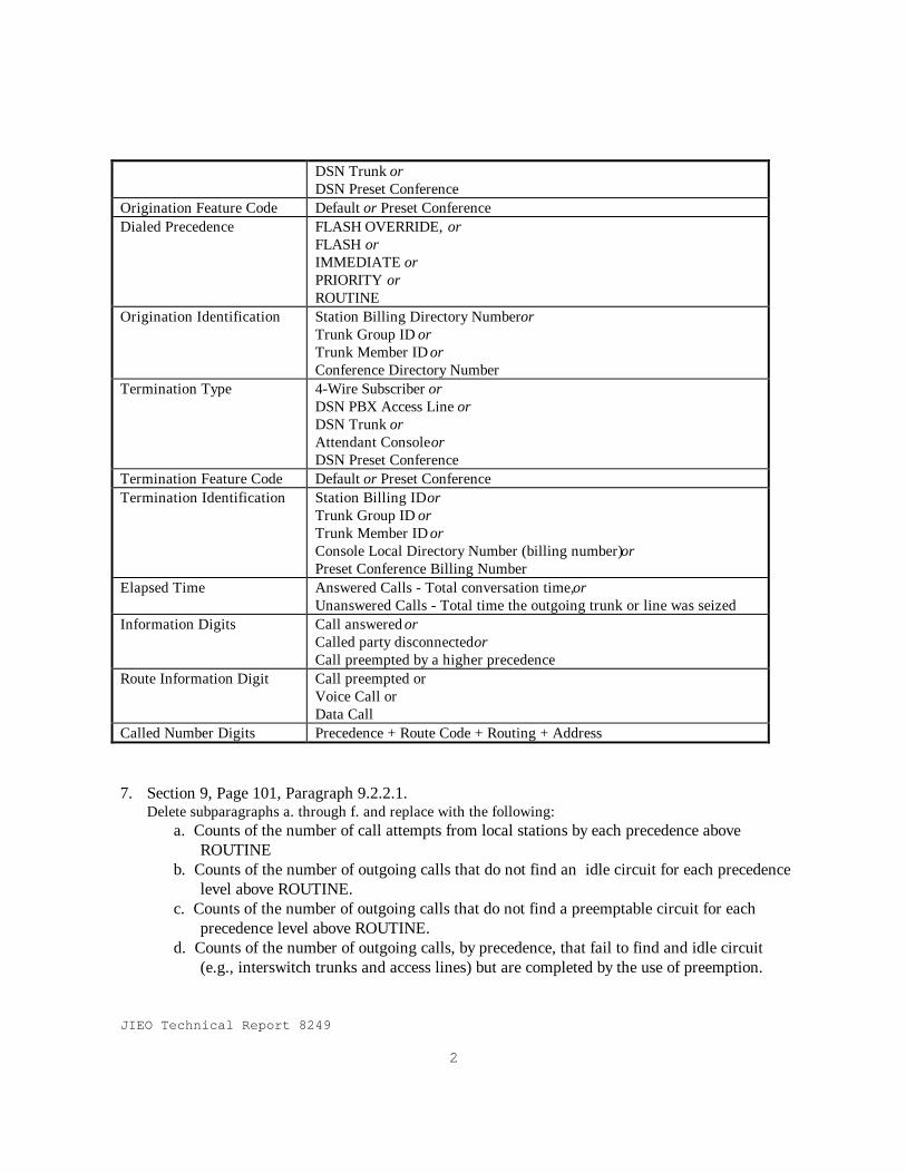
5. Section 7, Page 93, Paragraph 7.1.1. Delete the last sentence and replace with: “Conditional requirements are considered optional which may be specified in site specific contracts.” 6. Section 8, Page 99, Table 8-1. Delete current table and insert the following Table 8-1:
Table 8-1. DSN AMA Settable FieldsField Contents
Day 001 through 366Time Hour + Minute + secondOrigination Type 4-Wire Subscriber or
DSN PBX Access Line or
JIEO Technical Report 8249
2
DSN Trunk orDSN Preset Conference
Origination Feature Code Default or Preset ConferenceDialed Precedence FLASH OVERRIDE, or
FLASH orIMMEDIATE orPRIORITY orROUTINE
Origination Identification Station Billing Directory Number orTrunk Group ID orTrunk Member ID orConference Directory Number
Termination Type 4-Wire Subscriber orDSN PBX Access Line orDSN Trunk orAttendant Console orDSN Preset Conference
Termination Feature Code Default or Preset ConferenceTermination Identification Station Billing ID or
Trunk Group ID orTrunk Member ID orConsole Local Directory Number (billing number) orPreset Conference Billing Number
Elapsed Time Answered Calls - Total conversation time, orUnanswered Calls - Total time the outgoing trunk or line was seized
Information Digits Call answered orCalled party disconnected orCall preempted by a higher precedence
Route Information Digit Call preempted orVoice Call orData Call
Called Number Digits Precedence + Route Code + Routing + Address
7. Section 9, Page 101, Paragraph 9.2.2.1.Delete subparagraphs a. through f. and replace with the following:
a. Counts of the number of call attempts from local stations by each precedence aboveROUTINE
b. Counts of the number of outgoing calls that do not find an idle circuit for each precedencelevel above ROUTINE.
c. Counts of the number of outgoing calls that do not find a preemptable circuit for eachprecedence level above ROUTINE.
d. Counts of the number of outgoing calls, by precedence, that fail to find and idle circuit(e.g., interswitch trunks and access lines) but are completed by the use of preemption.

JIEO Technical Report 8249
3
Renumber subparagraph g. to subparagraph e.
8. Section 14, Page 123, Paragraph 14.1.Delete the last two sentences and replace with:“Because many DSN switching systems are located in Government owned buildings or in foreigncountries, some of the LSSGR requirements may not be applicable to all DSN switching systems.Therefore, physical and environmental specifications for DSN switching systems may be specifieddifferently in site specific contracts. If not separately specified, LSSGR requirements shall be used asguidelines in preparing specifications for preparing Government Furnished Facilities which will houseDSN switching systems.
9. Section 16, Page 131, Paragraph 16.5.3.5.Add the following sentence to the end of the paragraph.“FLASH and FLASH OVERRIDE C2 users shall be exempted from MSMC controls and provide dialtone.”
10. Section 16, Page 131, Paragraph 16.5.3.6.Delete paragraph and insert the following:
16.5.3.6 Dynamic Overload Control (DOC)With the advent of CCS7 and the ACC control, the development of DOC is no longer necessary as arequired switch feature. If DOC is desired for a site specific requirement in conjunction with otherSignaling schemes, The DOC specification in the LSSGR, Section 16, paragraph 5.3.6 and itssubparagraphs shall be required.
11. Section 16, Page 133, Paragraph 16.6.3.1.
Delete the second paragraph. - “ Code control requirement 6-1 apply … … … tactical networks.”
12. Section 18, Page 139.
Paragraph 18.1, line 6, correct typo by replacing “and” with “an” after “e.g.,”.
Paragraph 18.1, line 12, correct typo by adding a period “.” after the word “elements” and deletethe next word “and”. The next line, delete the last sentence beginning with “Therefore, the … .”.
Paragraph 18.1, delete the last paragraph beginning with “ The term “shall” … … ”.
1. Section 20, Page 145.
Paragraph 20.1, line 7, correct typo by deleting the word “are” between “as” and “Military”.
JIEO Technical Report 8249
1
Section 1
Introduction
This GSCR identifies the minimum essential and optionalfeatures, functional requirements and performance requirementsfor Stored Program Controlled Switches (SPCS) used in theDefense Switched Network (DSN) which is the circuit switchedportion of the Defense Information System Network (DISN). Itis intended to ensure that interoperability requirements amongDSN SPCS’s are clearly defined.
1.1 ApplicabilityThis report applies to all switches procured or leased for
installation in the DSN by Headquarters , Defense InformationSystems Agency (DISA), the military departments (MILDEPs),DISA field activities, and other Department of Defense (DoD)activities and government agencies responsible for theacquisition of DSN SPCS’s, excluding the Defense Red SwitchNetwork.
1.2 AuthorityThis specification is published in accordance with DoD
Directive (DoDD) 5105.19, Defense Information Systems Agency(DISA), 25 June 1991.
1.3 Referencesa. Joint Chiefs of Staff Instruction CJCSI 6215.01, Policy
For The Defense Switched Network, 1 February 1995.b. Defense Communications Agency Draft Circular (DCAC)
370-175-13, Defense Switched Network (DSN) SystemInterface Criteria, December 1994.
c. Defense Switched Network (DSN) Worldwide Routing andNumbering Plan (WWR&NP), published semi-annually by theDISA.
d. DISA Joint Interoperability Engineering Office (JIEO)Report 8247, DISN Architecture, September 1996.
JIEO Technical Report 8249
2
e. MIL-STD-188-194, Integrated Services Digital NetworkProfile, 1992.
f. Bellcore FR-64, Local Access and Transport Area (LATA)Switching Systems Generic Requirements (LSSGR), 1996.
g. Bellcore FR-NWT-000439, Operations Technology GenericRequirements, 1996.
h. Bellcore Special Report, SR-3476, National ISDN 1995and 1996, June 1995.
i. Bellcore GR-82-CORE, Signal Transfer Point GenericRequirement, 1996.
j. ANSI T1.111, Signaling System Number 7 (SS7) MessageTransfer Part (MTP), 1996.
k. ANSI T1.113, Signaling System Number 7 (SS7) IntegratedDigital Services Network (ISDN) User Part, 1995.
l. ANSI T1.408, Integrated Digital Services Network (ISDN)Primary Rate - Customer Installation Metalic InterfacesLayer 1 Specification, 1990.
m. ANIS T1.601, Integrated Digital Services Network(ISDN)- Basic Access Interface for Use on Metalic Loopsfor Application on the Network Side of the NT (Layer 1Specification), 1992.
n. ANSI T1.602, ISDN-Data-Link Layer Signal Specificationfor Application at The User-Network Interface, 1989.
o. ANSI T1.607, Digital Subscriber Signaling System Number1 (DSS1) - Layer 3, Signaling Specification forCircuit-Switched Bearer Services, 1990.
p. ANSI T1.610, Generic Procedures For The Control of ISDNSupplementary Services, 1994.
q. ANSI T1.613, ISDN Call Waiting Supplementary Service,1992.
r. ANSI T1.615, Digital Subscriber Signaling System Number1 (DSS1) Layer 3 Overview, 1992.
s. ANSI T1.616, ISDN Call Hold Supplementary Service,1992.
t. ANSI T1.619/619A, Integrated Services Digital Network(ISDN) Multi-Level Precedence and Preemption (MLPP)Service Capability, 1990/1994.
JIEO Technical Report 8249
3
u. ANSI T1.621, ISDN User-to-User Signaling SupplementaryService, 1992.
v. ANSI T1.632, ISDN Normal Call Transfer SupplementaryService, 1993.
w. ANSI T1.642, ISDN Call Deflection SupplementaryService, 1993.
x. ANSI T1.643, ISDN Explicit Call Transfer SupplementaryService, 1995.
y. ANSI T1.647, ISDN Conference calling SupplementaryService, 1995.
z. ITU-T I.320, ISDN Protocol Reference Model - ISDNOverall Network Aspects and Functions, 1993.
aa. ITU-T I.430, Basic User-Network Interface - Layer 1specification - Integrated Services Digital Network(ISDN) User-Network interfaces, 1995.
bb. ITU-T I.431, Primary Rate User-Network Interface -Layer 1 Specification, Revision 1, 1993.
cc. ITU-T G.802, Interworking Between Networks Based onDifferent Digital Hierarchies and Speech Encoding Laws,1989.
dd. ITU-T Q.920, DSS1-ISDN User-Network Interface Data LinkLayer - General Aspects, 1993.
ee. ITU-T Q.921, ISDN User-Network Interface - Data LinkLayer Specification - DSS1 Data Link Layer, 1989.
ff. ITU-T Q.931, DSS1-ISDN User-Network Interface Layer 3Specification for Basic control - DSS1 Network Layer,1993.
gg. ITU-T Q.932, DSS1 - Generic Procedures for Contrl ofISDN Supplementary Services - DSS1 Network Layer, 1993.
1.4 DISN ArchitectureThe DISN as defined by the Assistant Secretary of Defense
for Command, Control, Communications, and Intelligence(ASD/C3I) is: “A subelement of the Defense InformationInfrastructure, the DISN is the DoD’s consolidated worldwideenterprise-level telecommunications infrastructure thatprovides the end-to-end information transfer network for
JIEO Technical Report 8249
4
supporting military operations. It is transparent to itsusers, facilitates the management of information resources,and is responsive to national security and defense needs underall conditions in the most efficient manner”. DISN consistsof the following systems:
a. Voice Switched Systems• Defense Red Switch Network(DRSN) (Classified) - Global• Defense Switched Network (DSN) (Unclassified) - Global
b. Data Switched Systemsc. Imagery Systemsd. Transmission Systemse. Defense Operations Control Complex
A description of the DISN is contained in The DISN Strategy,July 1995. A detailed description of the DISN architecture iscontained in reference d.
1.5 GSCR ScopeThis GSCR applies to the DSN portion of the voice switched
systems of the DISN.
1.5.1 DSN ArchitectureThe DSN is the circuit switched portion of the DISN. The
DSN architecture is a two level network hierarchy consistingof Tandem Nodes (TN) and End Office Nodes (EN). DSN TNsinterconnected by interswitch trunks (ISTs) serve as thetransport backbone of the DSN. Users are not directly servedby the TNs. ENs are DSN access nodes to which all CustomerPremise Equipment (CPE) is connected. The EN provides DSNservice to the local community. Where it is economical forthe DOD, an EN may be connected via tie trunks to another ENto serve more than one local community. In general, all usersare connected to the EN and all traffic destined for locationsbeyond the local community is served through TNs.

JIEO Technical Report 8249
5
1.6 Switching ElementsThe following functional types of SPCSs will be used within
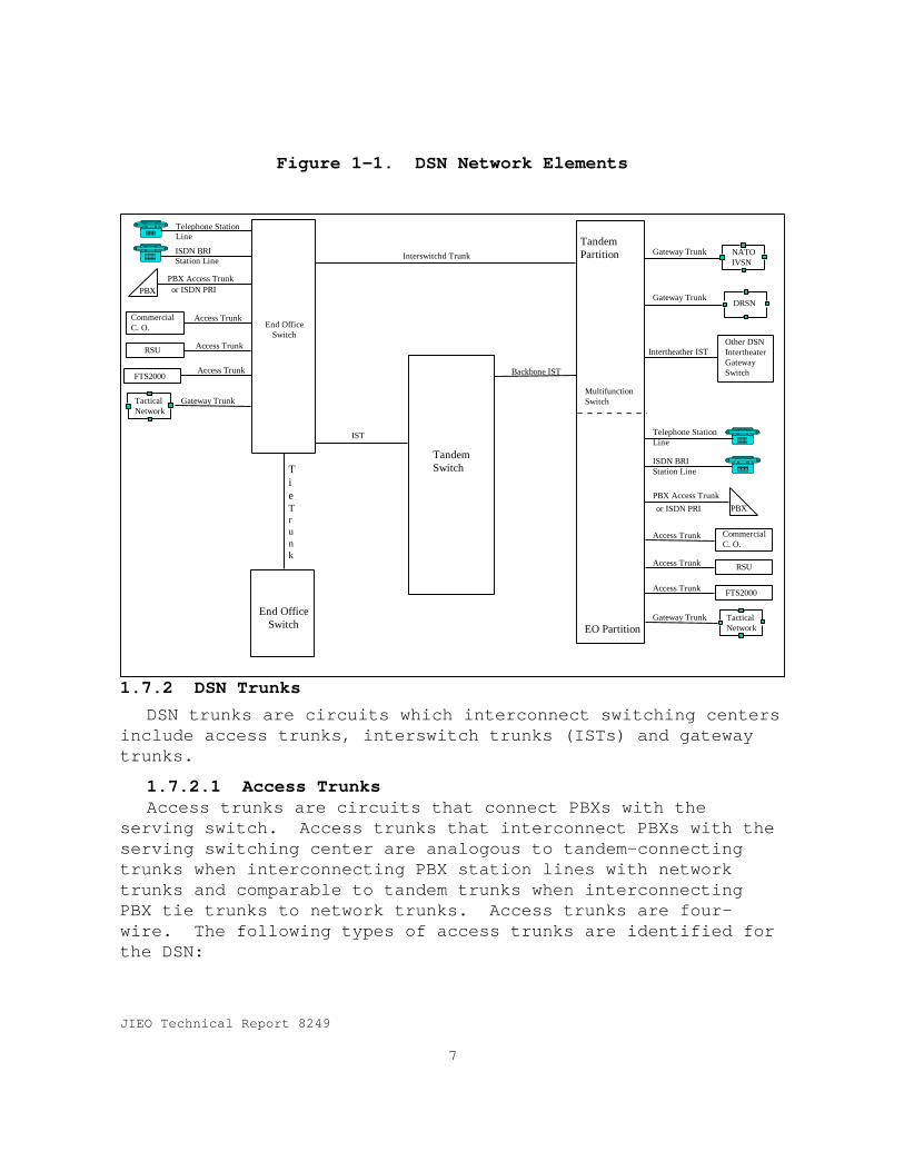
the DSN: the Tandem switch (TS), the End Office Switch(EOS),and the Multifunction switch (MFS). All DSN SPCSs aresupervised and interconnected to the DISN Administration,Operations, and Maintenance/Network Management (AO&M/NM)subsystems. Figure 1-1 illustrates the basic relationshipbetween the switch types and the users of the network. Noattempt is made to show actual switch connectivity.
1.6.1 Tandem SwitchThe TS is the SPCS in a DSN TN which provides long distance
services to users by interconnecting the EOs via the DSNbackbone network. TSs are equipped with network functionsonly. The TS may also provide translation functions whichenable it to serve as an inter-network gateway, e.g., as aninterface between PCM-24 (DS-1) and PCM -30 (E-1) trunks.
(Note: In past DSN documentation, the TS was called theStand Alone Switch).
1.6.2 End Office SwitchThe EOS is the SPCS, in a DSN EN, which serves as the
terminating switch (local loop). The major function of theEOS is to provide access to the DSN via connections to CPE.EOSs are equipped with user features tailored for a particularlocal community, and a set of required DSN features. EOSstranslate user information into networking information thatenables user traffic to be transported to distant locationsvia the DSN backbone. An EO is part of the DSN and has arequired, uniform set of DSN features (e.g., Multi-LevelPrecedence and Preemption) in addition to a set of userfeatures tailored for each local community. The EO is underDISA configuration control and is operationally controlled bythe DSN AO&M/NM system.
1.6.2.1 Private Branch ExchangeThe Private Branch Exchange (PBX) is similar to the EOS.
However, it is a CPE with only user features tailored forlocal users and is under customer (e.g., MILDEP) configuration
JIEO Technical Report 8249
6
control. In general, the use of PBXs is not recommended if anEO can provide the required features and services.
1.6.3 Multifunction SwitchThe Multifunction Switch (MFS) is an SPCS which combines the
functionality of both tandem and terminating switches. A DSNlocation which requires both TN and EN should be served by anMFS because it is generally more economical to provide andoperate a single switch than both a TS and an EOS. The MFS isdivided into two logical partitions, a terminating partitionwhich provides EO functions and a tandem partition whichprovides TS (backbone) functions. MFS’s can also serve asgateway switches for other networks.
1.7 DSN Lines and TrunksThe DSN lines and trunks, shown in Figure 1-1, illustrate
the major categories of transmission circuits into, out of,and within the DSN. The specific interface requirementsrelated to these transmission circuits of a DSN switch aredescribed in Section 10 and in DISA Circular 370-175-13. Thesignaling requirements to support these transmission circuitsare described in Section 6 of this specification.
1.7.1 DSN LinesDSN lines are defined as the transmission circuits that
allow access into and egress from the DSN.
Station lines are two-wire or four-wire connections from theend-user network interface (NI) to the line side of the EO orthe EO portion of the MFS. Station lines also connect to EO orMFS through a Private Branch Exchange (PBX) or centrex.Digital station lines also include Basic Rate Interface (BRI)and Primary Rate Interface (PRI) for ISDN.
JIEO Technical Report 8249
7
Figure 1-1. DSN Network Elements
End OfficeSwitch
CommercialC. O.
RSU
FTS2000
TacticalNetwork
Telephone StationLine
ISDN BRIStation Line
PBXPBX Access Trunk
Access Trunk
Access Trunk
Access Trunk
Gateway Trunk
CommercialC. O.
RSU
FTS2000
TacticalNetwork
PBX
NATOIVSN
DRSN
Telephone StationLine
ISDN BRIStation Line
PBX Access Trunk
Access Trunk
Access Trunk
Access Trunk
Gateway Trunk
Other DSNIntertheaterGatewaySwitch
Gateway Trunk
Gateway Trunk
MultifunctionSwitch
Backbone IST
Intertheather IST
Interswitchd Trunk
TandemSwitch
IST
or ISDN PRI
or ISDN PRI
End OfficeSwitch
TieTrunk
EO Partition
TandemPartition
1.7.2 DSN TrunksDSN trunks are circuits which interconnect switching centers
include access trunks, interswitch trunks (ISTs) and gatewaytrunks.
1.7.2.1 Access TrunksAccess trunks are circuits that connect PBXs with the
serving switch. Access trunks that interconnect PBXs with theserving switching center are analogous to tandem-connectingtrunks when interconnecting PBX station lines with networktrunks and comparable to tandem trunks when interconnectingPBX tie trunks to network trunks. Access trunks are four-wire. The following types of access trunks are identified forthe DSN:
JIEO Technical Report 8249
8
a. Private Branch Exchange (PBX) access trunk including bothon-base and off-base PBXs.
b. Remote Switch Unit (RSU) access trunks (extends DSNswitch line card service to the RSU)in many cases thesetrunks are optical carriers.
c. Commercial central office (CO) access trunk; this trunkprovides connection to the North American and Europeancommercial networks, including FTS2000.
d. Primary Rate Interface (PRI) service between the usernetwork interface and the serving switch are alsoconsidered access trunks.
1.7.2.2 DSN Interswitch Trunks (ISTs)DSN ISTs are transmission circuits between DSN switches.
The types of DSN ISTs follow:
a. Backbone. Backbone ISTs are those circuits that carryDSN traffic between: (1)the EO and the MFSs, (2)thenetwork side of an MFS and TSs, and (3) the network sideof adjacent MFSs or TSs.
b. Intertheater. Intertheater ISTs are those trunks thatcarry traffic between a MFS or a TS in one DSN theaterand a corresponding switch in another theater. ISTs maybe distinguished by the need to convert differences insignaling methods and data format, (e.g., conversion frompulse-code modulation (PCM)–30 to PCM-24).
c. Tie Trunks. Tie trunks interconnect any two EO switches.These trunks are established to provide service betweenthe communities of users assigned to the connectedswitches.
1.7.2.3 Gateway Trunks.Gateway trunks are those trunks that carry traffic between
DSN and other networks and may require special call treatmentand/or interfaces. The following types of gateway trunks areidentified for the DSN:
a. Tactical Network.
b. Defense RED Switch Network (DRSN).
c. Initial Voice Switched Network (IVSN).
JIEO Technical Report 8249
9
1.8 Connectivity to SubsystemsProvision shall be made to implement connectivity to various
subsystems (e.g., AO&M/NM, transmission, Digital Patch andAccess System (DPAS), timing and synchronization, etc.), whenrequired by the site specific contract.
1.9 Description of GSCRThe GSCR describes the features and functions of a switching
system and defines its interactions with user (customer)equipment, operations personnel, the physical environment, theelectrical environment, other interconnecting switchingsystems, and operating systems. The GSCR is generic in thatit does not describe the design or internal operation of asystem or distinguish one design from another. The GSCR isbased on American National Standards Institute (ANSI)standards and International Telecommunications Union (ITU)standards as implemented by Bellcore standards documents.International Telecommunications Union (ITU) standards arealso referenced where Bellcore documents do not meet theGovernments requirements or are required for switching systemsthat will be installed in countries that require interfaces tolocal commercial networks based on international standards.
Features not listed in the GSCR and extensions to featuresthat are listed, shall be able to be controlled (i.e.,modified, enabled or disabled) by Government operationspersonnel.
1.9.1 Relationship to Bellcore Commercial RequirementsThe GSCR is based on the current edition of the Bellcore
Local Access Transport Area (LATA) Switching Systems GenericRequirements (LSSGR), FR-64. The LSSGR references andimplements North American and international standards andrecommendations where they apply. Telecommunications, power,electrical, environmental standards and U.S. regulations areincluded in the LSSGR. The LSSGR is not a contractualdocument and does not impose specific requirements andspecifications on switch manufacturers unless specificallyrequired by a procurement document. It contains recommendedfeatures and objectives. Because this specification is based

JIEO Technical Report 8249
10
on the Bellcore LSSGR, the sections within this specificationcorrespond to the sections of the LSSGR. Sections 3 and 4 ofthe LSSGR are reserved for future use, therefore they are alsoreserved for future use in this specification. In addition,DSN switching systems will have Integrated Services DigitalNetwork (ISDN) capabilities, therefore, section 21 has beenadded to this specification. Section 21 references theBellcore specifications for ISDN services. Unless notedotherwise in the GSCR, the LSSGR feature and capabilitydescriptions and objectives are required for DSN switchingsystems.
1.9.2 Description of LSSGRThe LSSGR is a comprehensive source of Bellocre’s proposed
generic requirements and objectives for a switching systembased on the typical needs of the Bellcore Client Companies(BCCs). The LSSGR serves as a guide for the design andanalysis of new switching systems.
The LSSGR describes the features and functions of aswitching system by defining its interactions with thecustomer equipment, telephone company personnel, the physicalenvironment, the electrical environment, network elementsincluding other interconnecting switching systems, andOperations Systems (OSs). A complete description of the LSSGRcan be found in the LSSGR Section 1, paragraph 1.2.
1.9.3 Relationship to Commercial StandardsWhere appropriate, the GSCR is annotated with requirements
which apply to specific theaters. Theater requirementsinclude references to commercial standards such as theEuropean Telecommunications Standards Institute (ETSI).
JIEO Technical Report 8249
11
Section 2
Capabilities and Features
2.1 Capabilities and Features DescriptionsThis section defines GSCR switching system features. It is
based on Section 2 of the Bellcore LSSGR, FR-64. The featuresand capabilities listed in the following paragraphs anddefined in the Section 2, Chapter 2 of the LSSGR shall beincluded in DSN switching systems. The reference columncontains three types of references; (1) Bellcore FeatureSpecific Documents (FSD), (2) LSSGR paragraph references, e.g.6.2.1, and (3) definition only. Definition only referencesmean that a definition of the feature is in Section 2 of theLSSGR. LSSGR features and capabilities not listed areconsidered optional and may be required in site specificcontracts. This section also describes military uniquefeatures (MUFs) which are required in DSN switching systems.
Capabilities and features identified in tables 2-1 through2-15 are features listed in the Bellcore LSSGR and as such areconsidered an integral part of commercial-off-the-shelf (COTS)SPCSs. The Government assumes that no development work isrequired to provide these capabilities and features. COTScapabilities/features which require additional development dueto interactions with MUFs are considered optional unless theMUF interaction is specifically identified in this GSCR.Features which are followed by ** interact with MUFs. Themanner in which these features interact with MUFs arespecified in this GSCR or in ANSI specifications referenced inthis GSCR. Any additional features provided by the switchvendor, in addition to GSCR specifications, shall notinterfere with the operation of required features,particularly MUFs.
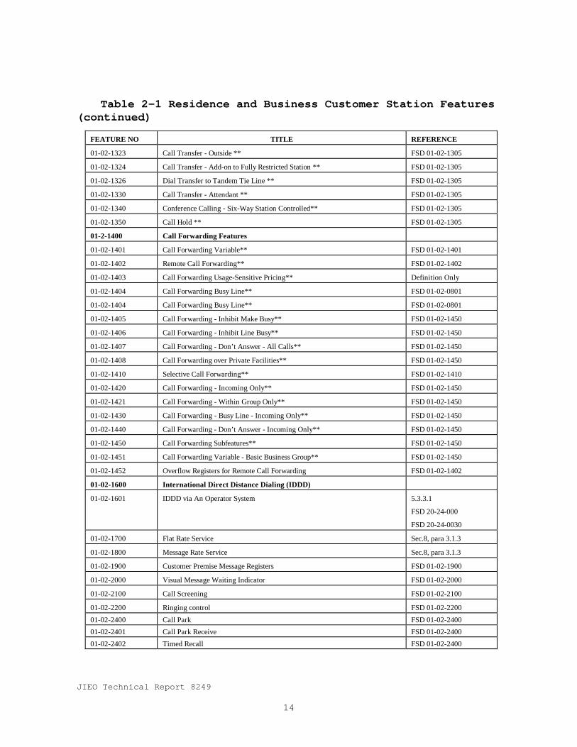
2.1.1 Residence and Business Customer Station FeaturesThe residence and business customer station features in
LSSGR, Volume 1, Section 2, shown in Table 2-1, shall beincluded in DSN switching systems. LSSGR features not in Table2-1 are considered optional.

JIEO Technical Report 8249
12
Table 2-1. Residence and Business Customer Station Features
FEATURE NO TITLE REFERENCE
01-01-0000 Residence and Business Customer Features
01-01-1000 Basic Business Group FSD 01-01-1000
01-01-1010 Business Group Line FSD 01-01-1000
01-01-1020 Business Group Dialing Plan FSD 01-01-1000
01-01-1030 Critical Interdigital Timing for Dialing Plan FSD 01-01-1000
01-01-1040 Intercom Dialing FSD 01-01-1000
01-01-1050 Customer Access Treatment Code Restrictions FSD 01-01-1000
01-01-1060 Semi-Restricted (Originating and Terminating) FSD 01-01-1000
01-01-1070 Fully-Restricted (Originating and Terminating) FSD 01-01-1000
01-01-1080 Business Group Direct Inward Dialing FSD 01-01-1000
01-01-1090 Business Group Direct Outward Dialing FSD 01-01-1000
01-01-1100 Business Group Automatic Identified Outward Dialing FSD 01-01-1000
01-01-1110 Distinctive Ringing/Call Waiting FSD 01-01-1110
01-01-1115 Distinctive Alerting/Call Waiting Indication FSD 01-01-1000
01-01-1120 Special Intercept Announcements FSD 01-01-1000
01-01-1130 Single Digit Dialing FSD 01-01-1000
01-01-1140 Simulated Facility Groups for In and Out Calls FSD 01-01-1000
01-01-3100 Standard Electronic Key Telephone Service Definition Only
01-02-0100 Individual Line FSD 01-02-0`00
01-02-0300 Line Restriction Services
01-02-0301 Manual Line Service FSD 01-02-0301
01-02-0302 Direct Connect FSD 01-02-0301
01-02-0500 Denied Terminating Service FSD 01-03-0500
01-02-0550 Denied Originating Service FSD 01-02-0301
01-02-0600 Code Restriction and Diversion FSD 01-02-0600
01-02-0610 Toll Restricted Service FSD 01-02-0600
01-02-0710 Voice/Data Protection FSD 01-02-0710
01-02-0750 Do Not Disturb Definition Only
01-02-0760 Selective Call Rejection FSD 01-02-0760
01-02-0801 Series Completion Service FSD 01-02-0801
01-02-0802 Multiline Hunt Service FSD 01-02-0802
01-02-0803 Circular Hunting FSD 01-02-0802
01-02-0804 Preferential Multiline Hunting FSD 01-02-0802
01-02-0805 Uniform Call Distribution FSD 01-02-0802
01-02-0806 Stop Hunt Key FSD 01-02-0802
01-02-0807 Queuing for Multiline Hunt Groups FSD 01-02-0802

JIEO Technical Report 8249
13
Table 2-1 Residence and Business Customer Station Features(continued)
FEATURE NO TITLE REFERENCE
01-02-0808 Delay Announcement for Queued Calls on Hunt Group FSD 01-02-0802
01-02-0809 Make Busy Key FSD 01-02-0802
01-02-0900 Dial Pulse Dialing 6.2.6.1
01-02-1000 Dual-Tone Multifrequency (DTMF) Dialing 6.2.6.2
01-02-1051 Calling Number Delivery FSD 01-02-1051
01-02-1052 Customer Originated Trace FSD 01-02-1052
01-02-1053 Calling Number Delivery Blocking
01-02-1054 Calling Number Delivery Blocking FSD 01-02-1053
01-02-1055 Calling Name Delivery Blocking FSD 01-02-1053
01-02-1056 Calling Identity Delivery and Suppression FSD 01-02-1053
01-02-1070 Calling Name Delivery FSD 01-02-1070
01-02-1090 Calling Identity Delivery on Call Waiting FSD 01-02-1090
01-02-1100 Abbreviated Dialing Features
01-02-1101 Speed Calling FSD 01-02-1101
01-02-1102 Customer-Changeable Speed Calling FSD 01-02-1101
01-02-1106 Business Group Speed Calling FSD 01-02-1101
01-02-1107 Business Group Customer-Changeable Speed Calling FSD 01-02-1101
01-02-1200 Call Waiting Features (See Paragraph GSCR 5.3.4.9 for MLPP
01-02-1201 Call Waiting ** FSD-01-02-1201
01-02-1202 Call Waiting Originating FSD 01-02-1205
01-02-1203 Dial Call Waiting FSD 01-02-1205
01-02-1204 Cancel Call Waiting FSD 01-02-1204
01-02-1205 Business Group Call Waiting FSD 01-02-1205
01-02-1208 Call Waiting Terminating FSD 01-02-1205
01-02-1210 Call Waiting Incoming Only FSD 01-02-1205
01-02-1215 Call Waiting Deluxe FSD 01-02-1215
01-02-1230 Outside Calling Area Alerting FSD 01-02-1230
01-02-1240 Business Group Automatic Callback FSD 01-02-1240
01-02-1250 Automatic Callback FSD 01-02-1250
01-02-1260 Automatic Recall FSD 01-02-1260
01-02-1300 Multiway Calling Features
01-02-1301 Three-Way Calling ** FSD 01-02-1301
01-02-1304 Usage Sensitive Three-Way Calling FSD 01-02-1304
01-02-1305 Add-On Transfer and Conference Calling Features FSD 01-02-1305
01-02-1310 Add-On Consultation Hold - Incoming Only FSD 01-02-1305
01-02-1320 Call Transfer Individual - All Calls ** FSD 01-02-1305
01-02-1321 Call Transfer - Internal Only ** FSD 01-02-1305
01-02-1322 Call Transfer - Individual - Incoming Only ** FSD 01-02-1305
JIEO Technical Report 8249
14
Table 2-1 Residence and Business Customer Station Features(continued)
FEATURE NO TITLE REFERENCE
01-02-1323 Call Transfer - Outside ** FSD 01-02-1305
01-02-1324 Call Transfer - Add-on to Fully Restricted Station ** FSD 01-02-1305
01-02-1326 Dial Transfer to Tandem Tie Line ** FSD 01-02-1305
01-02-1330 Call Transfer - Attendant ** FSD 01-02-1305
01-02-1340 Conference Calling - Six-Way Station Controlled** FSD 01-02-1305
01-02-1350 Call Hold ** FSD 01-02-1305
01-2-1400 Call Forwarding Features
01-02-1401 Call Forwarding Variable** FSD 01-02-1401
01-02-1402 Remote Call Forwarding** FSD 01-02-1402
01-02-1403 Call Forwarding Usage-Sensitive Pricing** Definition Only
01-02-1404 Call Forwarding Busy Line** FSD 01-02-0801
01-02-1404 Call Forwarding Busy Line** FSD 01-02-0801
01-02-1405 Call Forwarding - Inhibit Make Busy** FSD 01-02-1450
01-02-1406 Call Forwarding - Inhibit Line Busy** FSD 01-02-1450
01-02-1407 Call Forwarding - Don’t Answer - All Calls** FSD 01-02-1450
01-02-1408 Call Forwarding over Private Facilities** FSD 01-02-1450
01-02-1410 Selective Call Forwarding** FSD 01-02-1410
01-02-1420 Call Forwarding - Incoming Only** FSD 01-02-1450
01-02-1421 Call Forwarding - Within Group Only** FSD 01-02-1450
01-02-1430 Call Forwarding - Busy Line - Incoming Only** FSD 01-02-1450
01-02-1440 Call Forwarding - Don’t Answer - Incoming Only** FSD 01-02-1450
01-02-1450 Call Forwarding Subfeatures** FSD 01-02-1450
01-02-1451 Call Forwarding Variable - Basic Business Group** FSD 01-02-1450
01-02-1452 Overflow Registers for Remote Call Forwarding FSD 01-02-1402
01-02-1600 International Direct Distance Dialing (IDDD)
01-02-1601 IDDD via An Operator System 5.3.3.1
FSD 20-24-000
FSD 20-24-0030
01-02-1700 Flat Rate Service Sec.8, para 3.1.3
01-02-1800 Message Rate Service Sec.8, para 3.1.3
01-02-1900 Customer Premise Message Registers FSD 01-02-1900
01-02-2000 Visual Message Waiting Indicator FSD 01-02-2000
01-02-2100 Call Screening FSD 01-02-2100
01-02-2200 Ringing control FSD 01-02-2200
01-02-2400 Call Park FSD 01-02-2400
01-02-2401 Call Park Receive FSD 01-02-2400
01-02-2402 Timed Recall FSD 01-02-2400

JIEO Technical Report 8249
15
Table 2-1 Residence and Business Customer Station Features(concluded)
FEATURE NO TITLE REFERENCE
01-02-2800 Call Pick-Up Features
01-02-2801 Call Pick-Up** FSD 01-02-2800
01-02-2802 Directed Call Pick-UP FSD 01-02-2800
01-02-2803 Directed Call Pick-Up Without Barge-In FSD 01-02-2800
01-02-2804 Trunk Answer Any Station FSD 01-02-2800
2.1.2 Facility Access and ServicesThe facility access and service features in LSSGR, Volume
1, Section 2, shown in Table 2-2 shall be included in DSNswitching systems. LSSGR features not in Table 2-2 areconsidered optional.
Table 2-2. Facility Access and Services
FEATURE NO. TITLE REFERENCE
02-01-0000 Private Facility Access
02-01-0000 Private Facility Access FSD 02-01-0000
02-01-0010 Foreign Exchange Facilities FSD 02-01-0000
02-01-0020 800 Service (INWATS) Definition Only
02-01-0021 800 Service - Simulated Facility Groups FSD 02-01-0000
02-01-0022 Regulatory Two-Way WATS Definition Only
02-01-0030 Outward Wide Area Telecommunications Service (OUTWATS) FSD 02-01-0030
02-01-0031 OUTWATS - Simulated Facility Group FSD 02-01-0000
02-01-0040 Tie Facility Access FSD 02-01-0000
02-01-0110 Electronic Tandem Service (ETS) Access FSD 02-01-0000
02-01-0150 Dial Access to Private Facilities FSD 02-01-0000
02-01-0160 Tandem Tie Facility Dialing FSD 02-01-0000
02-01-1000 Paging Services
02-01-1010 Radio Paging FSD 02-01-0000
02-01-1020 Improved Radio Paging FSD 02-01-0000
02-01-1030 Loudspeaker Paging FSD 02-01-0000
02-01-1040 Code Calling FSD 02-01-0000
02-01-1050 Recorded Telephone Dictation FSD 02-01-0000
02-01-1060 9.6-kbps Data Switching Definition Only
02-01-1070 Switched Modem Pooling Definition Only
02-02-0000 Private Facility Features

JIEO Technical Report 8249
16
Table 2-2. Facility Access and Services (continued)FEATURE NO. TITLE REFERENCE
02-02-0010 Customer Control FSD 02-02-0010
02-02-0030 Selective Control of Facilities FSD 02-02-0010
02-02-0200 Outgoing Facility Group Queuing FSD 02-02-0200
02-02-0201 Deluxe Queuing FSD 02-02-0200
02-02-0202 Off-Hook Queuing FSD 02-02-0200
02-02-0203 On-Hook Queuing FSD 02-02-0200
02-02-0204 Post-Queue Routing FSD 02-02-0200
02-02-0205 Priority Queuing FSD 02-02-0200
02-02-0206 Service Protection FSD 02-02-0200
02-02-0300 Automatic Flexible Routing FSD 02-02-0300
02-02-0310 Automatic Route Selection FSD 02-02-0300
02-02-0320 Deluxe Automatic Route Selection FSD 02-02-0300
02-02-0330 Automatic Alternate Routing FSD 02-02-0300
02-02-0331 Uniform Numbering FSD 02-02-0300
02-02-0332 Off-Network-to-on-Network Conversion FSD 02-02-0300
02-02-0333 On-Network-to-Off-Network Conversion FSD 02-02-0300
02-02-0340 Facility Restriction Level (FRL) FSD 02-02-0300
02-02-0341 Alternate Facility Restriction Level FSD 02-02-0300
02-02-0350 Traveling Class Mark FSD 02-02-0300
02-02-0360 Expensive Route Warning Tone FSD 02-02-0300
02-02-0370 Manual/Time-of-Day Routing Control FSD 02-02-0300
02-02-0380 Special Calls FSD 02-02-0300
02-02-0390 Seven-Digit Home Numbering Plan Area (HNPA) Dialing FSD 02-02-0300
02-02-1000 Authorization/Account Codes
02-02-1010 Authorization Codes for AFR FSD 02-02-1010
02-02-1020 Account Codes for AFR FSD 02-02-1010
02-02-1030 Customer Dialed Account Recording (CDAR) FSD 02-02-1010
02-02-1100 Message Detail Recording (MDR)
02-02-1110 Message Detail Recording FSD 02-02-1110
02-02-1115 Generic Requirements for MDR Access Interfaces FSD 02-02-1115
02-02-1120 AMA Format for Transmitting Message Detail Recording Records via the Revenue
Accounting Office
FSD 02-02-1110

JIEO Technical Report 8249
17
Table 2-2. Facility Access and Services (concluded)FEATURE NO. TITLE REFERENCE
02-02-1200 Traffic Data Provision Features
02-02-1210 Traffic Data to Customer FSD 02-02-1200
02-02-1220 Customer-Polled Traffic Data FSD 02-02-1200
02-02-1230 Non-Usage Trunk Scan FSD 02-02-1200
02-02-1240 Locked Up Trunk Scan FSD 02-02-1200
02-02-1250 Automatic Circuit Assurance FSD 02-02-1200
02-02-1260 WATS Administration Data Definition Only
02-02-1270 Management Information System for Multiline Hunt Groups Definition Only
02-02-1280 Bulk Calling Line Identification FSD 02-02-1280
02-02-1290 Automatic Route Selection Traffic Management Definition Only
02-02-1300 Electronic Tandem Switching FSD 02-02-0300
02-02-1310 Improved Electronic Tandem Service/Network FSD 02-02-0300
2.1.3 Attendant FeaturesAll station features shall be available to attendants at
each console. In addition, the attendant features shown inTable 2-3 and in paragraphs 2.1.3.1 through 2.1.3.12 shall beincluded in DSN switching systems:
Table 2-3. Attendant Features
FEATURE NO TITLE
03-01-1010 Nondata Link Attendant Console
03-01-1020 Data Link Attendant Console
03-01-1030 Attendant Access to Code Calling
03-01-1040 Attendant Conference
03-01-1050 Attendant Camp-on (Nondata Link Console)
03-01-1060 Attendant Camp-on (Data Link Console)
03-01-1070 Indication of Camp-on
03-01-1080 Night Service
03-01-1090 Power Failure Transfer - Attendant
03-01-1100 Attendant Control of Facilities
03-01-1110 Dial Through Attendant
03-01-1120 Attendant Busy Line Verification
03-01-1130 Attendant Tie Trunk Busy Verification
03-01-1150 Attendant Emergency Override

JIEO Technical Report 8249
18
Table 2-3. Attendant Features (concluded)03-02-0010 Attendant ID on Incoming Calls
03-02-0030 Station Billing on Attendant-Handled Calls
03-02-0040 Trunk Group Busy Lamps
03-02-0050 Call Waiting Lamps for Attendant**
03-02-0060 Automatic Call Distribution
03-02-0070 Multiple Position Hunt with Queuing
01-02-3200 Centralized Attendant Service
2.1.3.1 Precedence and PreemptionThis feature shall allow an attendant to operate with MLPP
procedures as described in paragraph 2.2.1 and Section 5 ofthis specification. The console shall provide the ability todial precedence level calls.
2.1.3.2 Call DisplayA visual display shall be provided on the attendant
position. This display shall include precedence level, callednumber or digits dialed, calling number, class of service, andstatus of call.
2.1.3.3 Class of Service OverrideThis feature shall provide the attendant with the
capability to override any class of service marking for thepurpose of placing the required call.
2.1.3.4 Busy Override and Busy VerificationA busy line condition shall be capable of being overridden
only from attendant or maintenance technician facilities. Ifthe called line being verified is busy, off-hook supervisionshall be given to the attendant or maintenance technicianperforming the busy verification. When a verification code isused, all digits of the code must be dialed before cut-through to the line can be accomplished. Connections tocommercial C.O. access lines shall be restricted from busyverification access. The attendant shall have the capabilityto enter an existing busy line to inform the user of anincoming call. An override tone shall be provided to the busyline prior to the attendant entering the conversation, and thetone shall be repeated periodically as long as the attendantis connected. Selected stations may be classmarked to denyattendant break-in. In particular, it shall be possible toclassmark the lines of selected stations (e.g., all data and

JIEO Technical Report 8249
19
secure voice) to preclude the busy verification or busyoverride being applied to the selected station lines.
2.1.3.5 Interposition CallingThis feature shall allow an attendant at one attendant
position to call an attendant at another position.
2.1.3.6 Interposition TransferThis feature shall allow an attendant at one attendant
position to transfer a call to another attendant position.
2.1.3.7 Call ExtensionThe console shall be equipped so that the attendant can
extend calls to any station, trunk, or conference uponrequest.
2.1.3.8 Call HoldThe attendant shall be able to place a minimum of 3
incoming calls on hold when waiting for a busy line to becomeidle.
2.1.3.9 Two-Party Hold on ConsoleThis feature shall allow an attendant to hold a minimum of
3 calls on the console with both a calling and a calledstation or trunk connected.
2.1.3.10 Unattended ConsoleProvision shall be made for operation of multiple attendant
consoles. When a console is unattended, requests for serviceshall be automatically forwarded to a staffed console at thesame location. When a console is placed out of service, callson queue and on hold shall not be lost. When all attendantpositions are unattended, the switch shall automaticallyrevert first to Centralized Attendant Service and then toNight Service.
2.1.3.11 Audible Call IndicatorsThe console shall have the following audible call
indications:
a. Tone ringing (disabled while attendant is servicingcalls).
b. Capability to switch off ringing while the attendant isactive.
c. Adjustable tone and/or ringing intensity.
2.1.3.12 Automatic Recall of Attendant

JIEO Technical Report 8249
20
When an attendant extends a call to a station that is busyor does not answer within a preset time, the extended partyshall be automatically recalled to the console. Recalls shallbe transferred to the console that originally processed thecall. If that console is busy, the recall shall be placedinto the console queue; but if the console is out of service,the recall shall be routed to another console.
2.1.4 Customer Access InterfacesThe customer access interface features in LSSGR, Volume 1,
Section 2, shown in Table 2-4, shall be included in DSNswitching systems. LSSGR features not in Table 2-4 areconsidered optional.
Table 2-4. Customer Access Features
FEATURE NO. TITLE REFERENCE
04-01-0000 PBX Line FSD 04-01-0000
04-01-0100 PBX Line Features FSD 04-01-0000
04-02-0000 Direct Inward Dialing FSD 04-02-0000
04-03-0000 Automatic Identified Outward Dialing Definition Only
04-04-0000 Code Diversion FSD 01-02-0600
04-07-0000 Outward Calling Features for PBX Definition Only
04-07-0000 DTMF Outpulsing to PBX FSD 04-02-0000
05-01-0000 Loop Signaling Interfaces
05-01-0100 Analog Asynchronous Signaling Interface FSD 05-01-0100
05-01-0200 SPCS to CPE Data Interface for Analog Display Service FSD 05-01-0200
05-02-0000 Data Link Interfaces
05-02-0100 Dedicated Inband Analog Signaling Data Interface FSD 05-02-0100
05-02-0150 Simplified Message Desk Interface FSD 05-02-0150
05-03-0000 ISDN Basic Access GSCR Section 21
05-04-0000 ISDN Primary Access GSCR Section 21
2.1.5 Public Safety FeaturesThe public safety features in LSSGR, Volume 1, Section 2,
shown in Table 2-5 shall be included in DSN switching systems.LSSGR features not in Table 2-5 are considered optional.
JIEO Technical Report 8249
21
Table 2-5. Public Safety Features
FEATURE NO. TITLE REFERENCE
15-01-0000 Basic Emergency Service (911) FSD 15-01-0000
15-03-0000 Tracing of Terminating Calls FSD 15-03-0000
15-04-0000 Outgoing Call Tracing FSD 15-03-0000
15-05-0000 Tandem Call Trace FSD 15-03-0000
15-06-0000 Trace of A Call in Progress FSD 15-03-0000
15-07-0000 Group Alerting Service FSD 15-07-0000
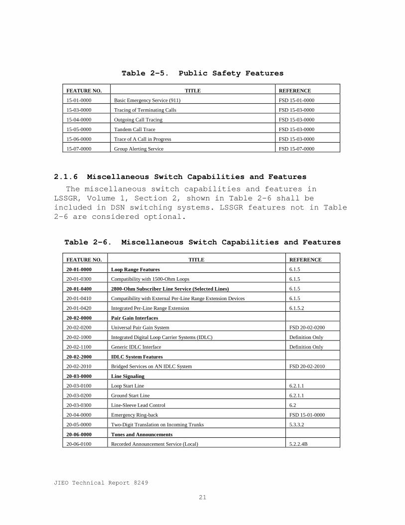
2.1.6 Miscellaneous Switch Capabilities and FeaturesThe miscellaneous switch capabilities and features in
LSSGR, Volume 1, Section 2, shown in Table 2-6 shall beincluded in DSN switching systems. LSSGR features not in Table2-6 are considered optional.
Table 2-6. Miscellaneous Switch Capabilities and Features
FEATURE NO. TITLE REFERENCE
20-01-0000 Loop Range Features 6.1.5
20-01-0300 Compatibility with 1500-Ohm Loops 6.1.5
20-01-0400 2800-Ohm Subscriber Line Service (Selected Lines) 6.1.5
20-01-0410 Compatibility with External Per-Line Range Extension Devices 6.1.5
20-01-0420 Integrated Per-Line Range Extension 6.1.5.2
20-02-0000 Pair Gain Interfaces
20-02-0200 Universal Pair Gain System FSD 20-02-0200
20-02-1000 Integrated Digital Loop Carrier Systems (IDLC) Definition Only
20-02-1100 Generic IDLC Interface Definition Only
20-02-2000 IDLC System Features
20-02-2010 Bridged Services on AN IDLC System FSD 20-02-2010
20-03-0000 Line Signaling
20-03-0100 Loop Start Line 6.2.1.1
20-03-0200 Ground Start Line 6.2.1.1
20-03-0300 Line-Sleeve Lead Control 6.2
20-04-0000 Emergency Ring-back FSD 15-01-0000
20-05-0000 Two-Digit Translation on Incoming Trunks 5.3.3.2
20-06-0000 Tones and Announcements
20-06-0100 Recorded Announcement Service (Local) 5.2.2.4B

JIEO Technical Report 8249
22
Table 2-6. Miscellaneous Switch Capabilities and Features (concluded)FEATURE NO. TITLE REFERENCE
20-06-0500 Special Information Tones FSD 20-06-0500
20-06-0600 Expanded Announcement System FSD 20-06-0600
20-07-0000 Ringing**
20-07-0100 Individual Line Ringing** 6.2.7.3
20-09-0000 Audible Ringing Tone** 5.2.2.1B,C
6.2.7.10
6.4.3.5
20-13-0000 Prevention of Service Requests by Induced Voltages 6.1.2
20-14-0000 Class of Service 5.3.2
20-16-0000 Nail-up of Non-Switched Circuits on A Local Switch FSD 20-16-0000
20-18-0000 Subscriber Loop Echo Return Control 7.2.2
20-20-0000 Automatic Number Identification (ANI) and Operator Number
Identification (ONI)
20-20-0000 Automatic Number Identification (ANI) FSD 20-20-0000
20-20-0100 Flexible ANI Information Digit Assignment FSD 20-20-0000
20-21-0000 Software Controlled Connection Loss 7.4.1
20-22-0000 Synchronization to Incoming DS1 Facilities LSSGR Sec. 10
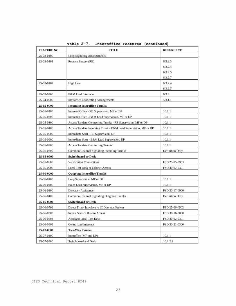
2.1.7 Interoffice FeaturesThe interoffice features in LSSGR, Volume 1, Section 2,
shown in Table 2-7 shall be included in DSN switching systems.LSSGR features not in Table 2-7 are considered optional.
Table 2-7. Interoffice Features
FEATURE NO. TITLE REFERENCE
25-01-0000 Interoffice Address Signaling
25-01-0300 Dial Pulsing 6.3.4.6
25-01-0400 Multifrequency Pulsing 6.4.1.2
25-01-1000 Common Channel Signaling (CCA) (See Section 6) Section 6
25-01-1100 CCS Exchange Access Interface FSD 25-01-1100
25-02-0000 Address Pulsing Control
25-02-0100 Immediate start 6.3.4.2
25-02-0200 Wink Start 6.3.4.3
25-02-0300 Delay Dial 6.3.4.4
25-03-0000 Call State Supervisory Signaling
JIEO Technical Report 8249
23
Table 2-7. Interoffice Features (continued)FEATURE NO. TITLE REFERENCE
25-03-0100 Loop Signaling Arrangements
25-03-0101 Reverse Battery (RB) 6.3.2.3
6.3.2.4
6.3.2.5
6.3.2.7
25-03-0102 High Low 6.3.2.4
6.3.2.7
25-03-0200 E&M Lead Interfaces 6.3.3
25-04-0000 Intraoffice Connecting Arrangements 5.3.1.1
25-05-0000 Incoming Interoffice Trunks
25-05-0100 Interend Office - RB Supervision, MF or DP 10.1.1
25-05-0200 Interend Office - E&M Lead Supervision, MF or DP 10.1.1
25-05-0300 Access Tandem Connecting Trunks - RB Supervision, MF or DP 10.1.1
25-05-0400 Access Tandem Incoming Trunk - E&M Lead Supervision, MF or DP 10.1.1
25-05-0500 Immediate Start - RB Supervision, DP 10.1.1
25-05-0600 Immediate Start - E&M Lead Supervision, DP 10.1.1
25-05-0700 Access Tandem Connecting Trunks 10.1.1
25-05-0800 Common Channel Signaling Incoming Trunks Definition Only
25-05-0900 Switchboard or Desk
25-05-0903 Verification Connections FSD 25-05-0903
25-05-0905 Local Test Desk or Cabinet Access FSD 40-02-0301
25-06-0000 Outgoing Interoffice Trunks
25-06-0100 Loop Supervision, MF or DP 10.1.1
25-06-0200 E&M Lead Supervision, MF or DP 10.1.1
25-06-0300 Directory Assistance FSD 30-17-0000
25-06-0400 Common Channel Signaling Outgoing Trunks Definition Only
25-06-0500 Switchboard or Desk
25-06-0502 Direct Trunk Interface to IC Operator System FSD 25-06-0502
25-06-0503 Repair Service Bureau Access FSD 30-16-0000
25-06-0504 Access to Local Test Desk FSD 40-02-0301
25-06-0505 Centralized Intercept FSD 30-21-0300
25-07-0000 Two-Way Trunks
25-07-0100 Interoffice (MF and DP) 10.1.1
25-07-0300 Switchboard and Desk 10.1.2.2

JIEO Technical Report 8249
24
Table 2-7. Interoffice Features (concluded)FEATURE NO. TITLE REFERENCE
25-08-0000 Outgoing Centralized Automatic Message Accounting (CAMA) Trunks 10.1
25-09-0000 Direct Ports to PCM Facilities
25-09-0100 Direct Ports to DS1 Facilities 10.2.1
25-09-0200 Direct Ports to DS1C Facilities 10.2.2
2.1.8 Call Processing FeaturesThe call processing features in LSSGR, Volume 1, Section 2,
shown in Table 2-8 shall be included in DSN switching systems.LSSGR features not in Table 2-8 are considered optional.
Table 2-8. Call Processing Features
FEATURE NO. TITLE REFERENCE
30-01-0000 Overload Control and Protection of Essential Services
30-01-0100 Automatic Internal Overload Control 5.3.8
30-01-0200 Essential Service Protection 5.3.9
30-02-0000 Customer Line Checks
30-02-0100 Power Cross Test 5.2.1.2
30-02-0200 Ringing Continuity Test 5.2.2.1A
6.2.4.2
30-03-0000 Numbering Plan 5.3.3
30-04-0000 Direct Distance Dialing 5.3.3
30-05-0000 Permanent Signal 5.2.1.4C
30-06-0000 Digit Interpretation 5.3.3
30-07-0000 Digit Interpretation Timing
30-07-0100 Partial Dial 5.2.1.4C
5.2.2.3C
30-07-0200 Critical Interdigit Timing 5.3.3.1
30-07-0300 End of Dial 5.3.3.1
30-08-0000 Screening 5.3.4
30-09-0000 Routing 5.3.5
30-10-0000 Alternate Routing 5.3.5.2
30-12-0000 Subscriber Directory Number Dialing Features
30-12-0100 Prefix ‘1’ for InterNPA Calls 5.3.3.1A
30-12-0200 Prefix ‘1’ for 10-Digit Calls 5.3.3.1A

JIEO Technical Report 8249
25
Table 2-8. Call Processing Features (concluded)FEATURE NO. TITLE REFERENCE
30-12-0300 No Prefix Required for 7- or 10-Digit Calls 5.3.3.1A
30-12-0301 Prefix ‘1’ Allowed on 10-Digit Calls Only 5.3.3.1A
30-12-0302 Prefix ‘1’ Allowed on 7- or 10-Digit Calls 5.3.3.1A
30-13-0000 Foreign Area Translation (6-Digit Translation) 5.3.3.1B
30-14-0000 Operator Assistance - Dial ‘0’ 5.3.3.1
30-15-0000 Dial ‘0’ Plus Seven or Ten Digits 5.3.3.1
30-16-0000 Service Codes
30-16-0100 Service Codes N11 FSD 30-16-0000
30-17-0000 Interface to Directory Assistance System FSD 30-17-0000
30-18-0000 Custom Calling Service Access Codes 5.3.3.1C
30-19-0000 Intersystem Address Outpulsing (MF and DP)
30-19-0100 Outpluse 2-10 Digits MF and DP 5.3.6
30-19-0200 Delete Digits (Up to Seven) 5.3.6
30-19-0300 Prefix Digits (Up to Three) 5.3.6
30-19-0400 Outpluse Seven Digits for Valid Service Codes 5.3.6
30-20-0000 Reception of Outpulsing From Other Systems (MF and DP) 5.3.3.2
30-21-0000 Intercept Routing for Calls to Blank, Changed, Disconnected, or Unassigned
Directory Numbers
30-21-0100 Announcement - Local or Remote 5.2.2.3E
30-21-0200 Operator 5.2.2.3E
30-21-0300 Interface to Intercept System FSD 30-21-0300
30-23-0000 Remote Switching Units FSD 30-23-2300
30-25-0000 Timed Release Disconnect 6.3.5.2
30-26-0000 Tandem Capability
30-26-0100 Limited Local Tandem Switching Section 20
30-26-0200 Local Intertandem Switching Section 20
30-28-0000 Screening List Feature
30-28-0100 Visual Screening List Editing FSD 30-28-0100
30-29-0100 Numbering Plan Area Split Management FSD 30-29-0100
30-33-0000 Release to Pivot Network Capability FSD 30-29-0100
2.1.9 Database ServicesThe database service features in LSSGR, Volume 1, Section
2, shown in Table 2-9 shall be included in DSN switchingsystems. LSSGR features not in Table 2-9 are consideredoptional.

JIEO Technical Report 8249
26
Table 2-9. Database Services
FEATURE NO. TITLE REFERENCE
31-01-0000 Service Switching Point (SSPs) FSD 31-01-0000
32-10-1000 Public Switched Digital Service FSD 32-10-1000
2.1.10 System Maintenance FeaturesSystem maintenance features in LSSGR, Volume 1, Section 2,
and shown in Table 2-10 shall be included in DSN switchingsystems. Feature specification are defined in Bellcorepublication FR-439 Operations Technology Generic Requirements(OTGR).
Table 2-10. System Maintenance Features
FEATURE NO. TITLE
35-01-0000 Trouble Detection
35-01-0100 Hardware Redundancy
35-01-0200 Hardware Checks
35-01-0300 Software Checks
35-01-0310 Continuous Automatic Tests
35-01-0311 Audit Programs
35-01-0312 Sanity Tests
35-01-0320 Per-Call and Per-Operation Trouble Detection Tests
35-01-0321 Call Processing Database Troubles Detection
35-01-0322 Call Processing resource Availability Test
35-01-0323 Ineffective Attempt Detection
35-01-0324 Cut-Off Call Trouble Detection
35-01-0325 Network Path Integrity End-to-End Test
35-01-0326 Assurance of Customer Privacy of Communications Test
35-01-0327 Tip and Ring Polarity Tests
35-01-0330 Periodic Automatic Tests
35-01-0340 Semiautomatic Trouble Detection Tests
35-01-0350 Manual Tests
35-01-0360 Inhibit of Trouble Detection
35-02-0000 Service Recovery
35-02-0100 Fault Recovery Programs
35-02-0200 Initializations

JIEO Technical Report 8249
27
Table 2-10. System Maintenance Features (concluded)FEATURE NO. TITLE
35-02-0300 Automatic Service Recovery
35-02-0310 Automatic Treatment of Errors
35-02-0320 Automatic Treatment of Faults
35-02-0330 Equipment Selection Procedures
35-02-0340 Out-of-Service Limits for Server Group Equipment
35-02-0400 Manual Service Recovery
35-03-0000 Trouble Notification
35-03-0100 Three-Level Alarm Structure
35-03-0200 Audible Alarms
35-03-0300 Visual Alarm Indicators
35-03-0400 Output Messages
35-03-0500 Trouble Status Indicators
35-03-0600 Office Alarm Subsystem
35-03-0700 Alarm Inhibit
35-04-0000 Trouble Verification
35-05-0000 Trouble Isolation
35-05-0100 Trouble Location Procedure
35-05-0200 Diagnostics
35-05-0300 Error Analysis
35-06-0000 Repair
35-07-0000 Maintenance Person-Switching System Interface
35-07-0100 Maintenance Control Center (MCC)
35-07-0200 Switching System Control and Display Interface
35-07-0210 Alarm Release
35-07-0220 Alarms Transfer
35-07-0300 Switching System Maintenance I/O Devices
35-07-0400 Extended Maintenance Center
35-08-0000 Remote Maintenance Center
35-09-0000 Maintenance Measurements
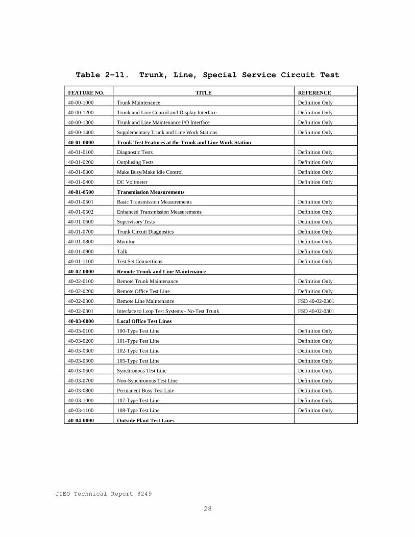
2.1.11 Trunk, Line, Special Service Circuit Test FeaturesTrunk, line, and special circuit test features in LSSGR,
Volume 1, Section 2, shown in Table 2-11 shall be included inDSN switching systems.
JIEO Technical Report 8249
28
Table 2-11. Trunk, Line, Special Service Circuit Test
FEATURE NO. TITLE REFERENCE
40-00-1000 Trunk Maintenance Definition Only
40-00-1200 Trunk and Line Control and Display Interface Definition Only
40-00-1300 Trunk and Line Maintenance I/O Interface Definition Only
40-00-1400 Supplementary Trunk and Line Work Stations Definition Only
40-01-0000 Trunk Test Features at the Trunk and Line Work Station
40-01-0100 Diagnostic Tests Definition Only
40-01-0200 Outplusing Tests Definition Only
40-01-0300 Make Busy/Make Idle Control Definition Only
40-01-0400 DC Voltmeter Definition Only
40-01-0500 Transmission Measurements
40-01-0501 Basic Transmission Measurements Definition Only
40-01-0502 Enhanced Transmission Measurements Definition Only
40-01-0600 Supervisory Tests Definition Only
40-01-0700 Trunk Circuit Diagnostics Definition Only
40-01-0800 Monitor Definition Only
40-01-0900 Talk Definition Only
40-01-1100 Test Set Connections Definition Only
40-02-0000 Remote Trunk and Line Maintenance
40-02-0100 Remote Trunk Maintenance Definition Only
40-02-0200 Remote Office Test Line Definition Only
40-02-0300 Remote Line Maintenance FSD 40-02-0301
40-02-0301 Interface to Loop Test Systems - No-Test Trunk FSD 40-02-0301
40-03-0000 Local Office Test Lines
40-03-0100 100-Type Test Line Definition Only
40-03-0200 101-Type Test Line Definition Only
40-03-0300 102-Type Test Line Definition Only
40-03-0500 105-Type Test Line Definition Only
40-03-0600 Synchronous Test Line Definition Only
40-03-0700 Non-Synchronous Test Line Definition Only
40-03-0800 Permanent Busy Test Line Definition Only
40-03-1000 107-Type Test Line Definition Only
40-03-1100 108-Type Test Line Definition Only
40-04-0000 Outside Plant Test Lines
JIEO Technical Report 8249
29
Table 2-11. Trunk, Line, Special Service Circuit Test (continued)FEATURE NO. TITLE REFERENCE
40-04-0100 Dialable Cable Pair Locator Tone FSD 40-04-0100
40-04-0300 DTMF Station Test Circuit Definition Only
40-08-0000 Automatic Progression Trunk and Service Circuit Testing Definition Only
40-09-0000 Automatic Line Insulation Tests Definition Only
40-10-0000 System Line Insulation Test Definition Only
40-11-0000 Test Incoming Trunks in Tandem or Local State Definition Only
40-12-0000 Automatic Retest (Treatment) of Permanent Signals Definition Only
40-12-0100 Lines 5.2.2.3
40-12-0200 Trunks (False Seizures) 5.2.2.3
40-17-0000 Manual Testing
40-17-0100 Manual Test of Lines Definition Only
40-17-0200 Manual Test of Trunks Definition Only
40-18-0000 Treatment of Trunk with Machine-Detected Interoffice Irregularities
40-18-0100 Removal from Service of Trunks with Machine Detected Interoffice Irregularities Definition Only
40-18-0200 Selective Suppression of MDII Messages Definition Only
40-18-0500 Call Irregularities due to Trunk Failures
40-18-0501 Detection, Reporting, Automatic Diagnostic, and Trunk Removal Safeguards Definition Only
40-18-0502 Trunk Error Analysis Definition Only
40-18-0600 Identification of Tip-Ring Reversals Associated with Spurious Answer Signals Definition Only
40-19-0000 Demand Listing of Trunk Numbers of a Specified Trunk Group Definition Only
40-20-0000 Print the Trunk-out-of-Service (TOS) List Definition Only
40-21-0000 Diagnose the TOS List Definition Only
40-22-0000 Trunk Group - Remove from Service (Make Busy) Definition Only
40-23-0000 Trunk Group - Restore to Service (Make Idle) Definition Only
40-24-0000 Transmission Testing of Trunk Groups Definition Only
40-27-0000 Line Access to TLWS Definition Only
40-28-0000 Multiple Trunk Test Capability Definition Only
40-29-0000 Trunk-to-Trunk Test Connection Definition Only
40-30-0000 Plug Up Lists for Trouble Intercept Routing Definition Only
40-31-0000 Transmission Level Point Adjustment Definition Only
40-32-0000 Carrier Group Alarm (CGA) Definition Only
40-33-0000 In-Service Facility Performance Monitoring Definition Only
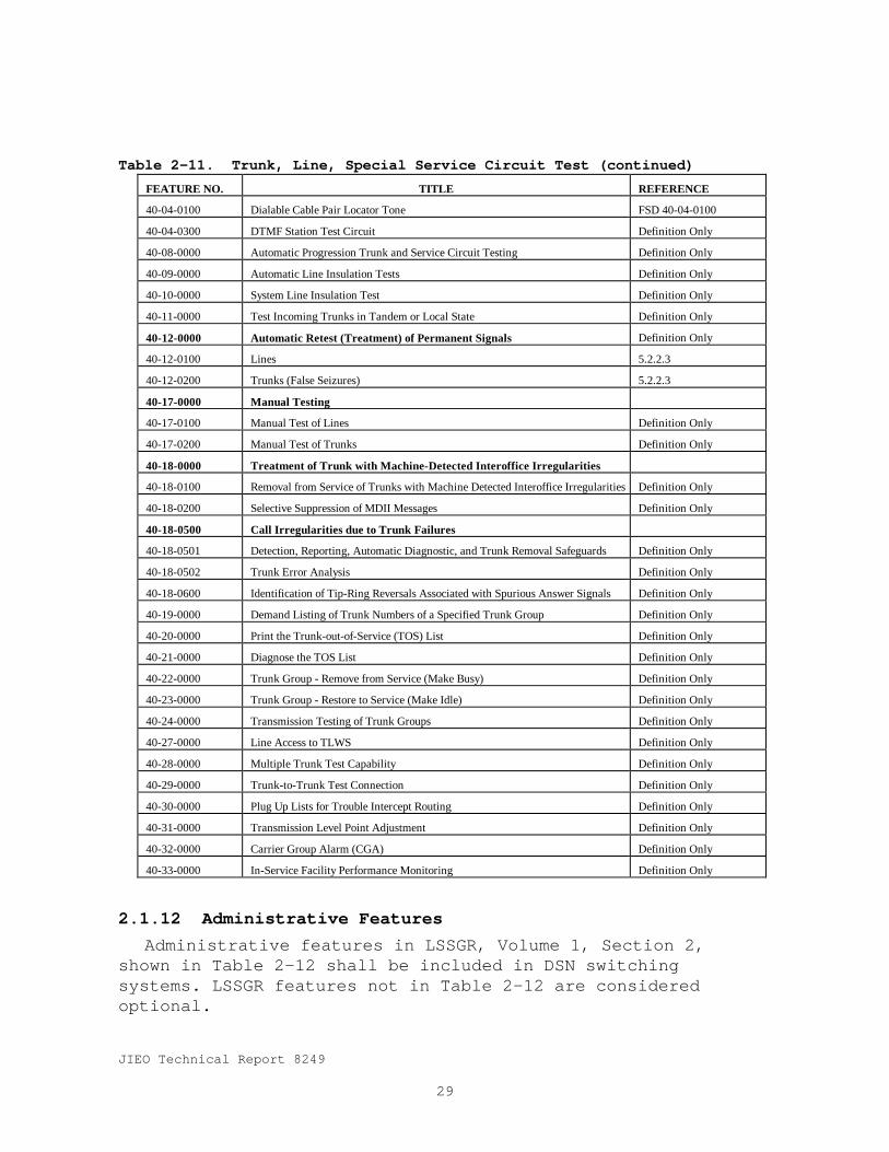
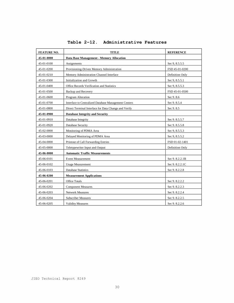
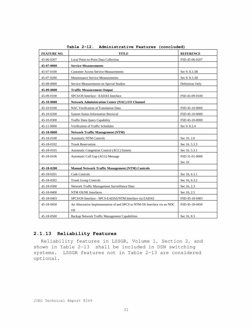
2.1.12 Administrative FeaturesAdministrative features in LSSGR, Volume 1, Section 2,
shown in Table 2-12 shall be included in DSN switchingsystems. LSSGR features not in Table 2-12 are consideredoptional.
JIEO Technical Report 8249
30
Table 2-12. Administrative Features
FEATURE NO. TITLE REFERENCE
45-01-0000 Data Base Management - Memory Allocation
45-01-0100 Assignments Sec 9, 8.5.5.5
45-01-0200 Provisioning-Driven Memory Administration FSD 45-01-0200
45-01-0210 Memory Administration Channel Interface Definition Only
45-01-0300 Initialization and Growth Sec 9, 8.5.5.1
45-01-0400 Office Records Verification and Statistics Sec 9, 8.5.5.3
45-01-0500 Backup and Recovery FSD 45-01-0500
45-01-0600 Program Alteration Sec 9. 8.6
45-01-0700 Interface to Centralized Database Management Centers Sec 9. 8.5.4
45-01-0800 Direct Terminal Interface for Data Change and Verify Sec 9. 8.5
45-01-0900 Database Integrity and Security
45-01-0910 Database Integrity Sec 9. 8.5.5.7
45-01-0920 Database Security Sec 9. 8.5.5.8
45-02-0000 Monitoring of PDMA Area Sec 9, 8.5.5.3
45-03-0000 Delayed Monitoring of PDMA Area Sec 9, 8.5.5.2
45-04-0000 Printout of Call Forwarding Entries FSD 01-02-1401
45-05-0000 Teletypewriter Input and Output Definition Only
45-06-0000 Automatic Traffic Measurements
45-06-0101 Event Measurement Sec 9. 8.2.2.1B
45-06-0102 Usage Measurement Sec 9. 8.2.2.1C
45-06-0103 Database Statistics Sec 9. 8.2.2.8
45-06-0200 Measurement Applications
45-06-0201 Office Totals Sec 9. 8.2.2.2
45-06-0202 Component Measures Sec 9. 8.2.2.3
45-06-0203 Network Measures Sec 9. 8.2.2.4
45-06-0204 Subscriber Measures Sec 9. 8.2.2.5
45-06-0205 Validity Measures Sec 9. 8.2.2.6
JIEO Technical Report 8249
31
Table 2-12. Administrative Features (concluded)FEATURE NO. TITLE REFERENCE
45-06-0207 Local Point-to-Point Data Collection FSD 45-06-0207
45-07-0000 Service Measurements
45-07-0100 Customer Access Service Measurements Sec 9. 8.3.3B
45-07-0200 Maintenance Service Measurements Sec 9. 8.3.3D
45-08-0000 Service Measurements on Special Studies Definition Only
45-09-0000 Traffic Measurement Output
45-09-0100 SPCS/OS Interface - EADAS Interface FSD 45-09-0100
45-10-0000 Network Administration Center (NAC) I/O Channel
45-10-0100 NAC Verification of Translation Data FSD 45-10-0000
45-10-0200 System Status Information Retrieval FSD 45-10-0000
45-10-0300 Traffic Data Query Capability FSD 45-10-0000
45-11-0000 Verification of Traffic Schedules Sec 9. 8.2.4
45-18-0000 Network Traffic Management (NTM)
45-18-0100 Automatic NTM Controls Sec 16. 2.0
45-18-0102 Trunk Reservation Sec 16. 5.3.3
45-18-0105 Automatic Congestion Control (ACC) System Sec 16. 5.3.1
45-18-0106 Automatic Call Gap (ACG) Message FSD 31-01-0000
Sec 16
45-18-0200 Manual Network Traffic Management (NTM) Controls
45-18-0201 Code Controls Sec 16, 6.3.1
45-18-0202 Trunk Group Controls Sec 16, 6.3.2
45-18-0300 Network Traffic Management Surveillance Data Sec 16, 2.3
45-18-0400 NTM OS/NE Interfaces Sec 16, 2.5
45-18-0403 SPCS/OS Interface - SPCS-EADAS/NTM Interface via EADAS FSD 45-18-0403
45-18-0450 An Alternative Implementation of and SPCS to NTM OS Interface via an NDC
OS
FSD 45-18-0450
45-18-0500 Backup Network Traffic Management Capabilities Sec 16, 8.3
2.1.13 Reliability FeaturesReliability features in LSSGR, Volume 1, Section 2, and
shown in Table 2-13 shall be included in DSN switchingsystems. LSSGR features not in Table 2-13 are consideredoptional.

JIEO Technical Report 8249
32
Table 2-13. Reliability Features
FEATURE NO. TITLE REFERENCE
46-10-0000 Frequency of Service Impairment
46-10-0100 Cutoff Calls Sec 12, 12.2
46-10-0200 Ineffective Machine Attempts Sec 12, 12.3
46-10-0310 Hardware Cutoff Rate Sec 12, 4.3, 5.4
46-10-0410 Outage Frequency Measurements Sec 12, 7.2.2, 9
46-20-0000 Downtime
46-20-0110 Individual Termination Hardware Downtime Sec 12, 4.2, 5.1
46-20-0210 Multitermination Hardware Downtime Sec 12, 4.2, 5.3
46-20-0310 Total Capability Hardware Downtime Sec 12, 5.3
46-20-0410 Downtime Performance Measurements Sec 12, 7.2.1, 9-11
46-20-0600 System Operations Capability
46-20-0601 Control Sec 12, 10.6
46-20-0602 Visibility of Fault Sec 12, 10.7
46-20-0603 Diagnostic Capability Sec 12, 10.7
46-30-0000 Service Life Sec 12, 2.2
2.1.14 Cutover and Growth FeaturesCutover and growth features in LSSGR, Volume 1, Section 2,
shown in Table 2-14 shall be included in DSN switchingsystems.
Table 2-14. Cutover and Growth Features
FEATURE NO. TITLE
50-01-0000 Online Growth Procedures and Tests
50-02-0000 Automatic Board-to-Board Testing
50-03-0000 Skip Software Release Capability
2.1.15 Billing and Comptroller FeaturesBilling and comptroller features in LSSGR, Volume 1,
Section 2, shown in Table 2-15 shall be included in DSNswitching systems. LSSGR features not shown in Table 2 -15 areconsidered optional.

JIEO Technical Report 8249
33
Table 2-15. Billing and Comptroller Features
FEATURE NO. TITLE REFERENCE
55-01-0000 Automatic Message Accounting (AMA)
55-01-0100 Local Automatic Message Accounting Section 8
55-01-0400 AMA Teleprocessing Definition Only
55-01-0500 AMA Data Networking Definition Only
55-02-0000 AMA Recording for Special Studies
55-02-0200 Complaint Observing Section 8
55-02-0400 Subscriber Line Usage Section 8
55-03-0000 AMA Data for Billing Services
55-03-0100 Class of Service Billing Section 8
55-03-0200 ANA Detailed Record on Timed Message Unit (MU) Calls and Untimed Section 8
55-03-0300 Calling Area Assignments 5.3.2, Sec 8
55-03-0500 Directory Assistance Charging FSD 30-17-0000
55-03-0510 AMA Recording of ‘555’ Calls Section 8
55-03-0600 Free calls 5.2.2.1E, Sec 8
55-03-0700 AMA Recording of Customer Evoked Vertical Services Definition Only
55-05-0000 Usage-Sensitive Billing Option on Normally Flat Rate Features Definition Only
55-06-0000 Verification of Billing Number Assignments Section 8
55-07-0000 AMA Records of WATS Calls Definition Only
2.2 Military Unique Features (MUF)The following features are unique to DSN switching systems.
Call processing for these functions is described in Section 5of this specification.
2.2.1 Multi-Level Precedence and Preemption (MLPP)The switch shall provide precedence levels, designated zero
through four, as shown in Table 2-16, with service preferenceaccording to level. Precedence level four will be used fornormal ROUTINE calls. Precedence level zero is the highestlevel precedence.

JIEO Technical Report 8249
34
Table 2-16. Precedence Levels
PRECEDENCE LEVEL (PL) PRECEDENCE
0 FLASH OVERRIDE1 FLASH2 IMMEDIATE3 PRIORITY4 ROUTINE
2.2.1.1 DescriptionThe MLPP service applies to a domain only, i.e.,
subscribers and the network and access resources that belongto the domain. Connections and resources that belong to acall from an MLPP subscriber shall be marked with a precedencelevel and domain identifier and shall only be preempted bycalls of higher precedence from MLPP users in the same domain.The maximum precedence level of a subscriber is set at thesubscription time by the DSN network administrator based onthe subscriber’s validated need. The subscriber may select aprecedence level up to and including the maximum authorizedprecedence level on a per call basis.
Precedence provides preferred handling of MLPP servicerequests. It involves assigning and validating priority levelsto calls and prioritized treatment of MLPP service requests.
Precedence calls (MLPP calls that have a higher precedencethan the lowest level of precedence) that are not responded toby the called party (e.g., call unanswered and/orunacknowledged, called party busy with call of equal or higherprecedence, or called party busy and nonpreemptable) areoptionally diverted to a predetermined alternate party. Thisalternate party shall be another valid network address. If noalternate party is selected by the called party, the treatmentof these calls shall be the same as a basic call; however, aprecedence call blocked indication will be sent to the callingparty for precedence calls that encounter busy with equal orhigher precedence conditions.
Preemption may take one of two forms. First, the calledparty may be busy with a lower precedence call which must bepreempted in favor of completing the higher precedence callfrom the calling party. Second, the network resources may bebusy with calls some of which are of lower precedence than the
JIEO Technical Report 8249
35
call requested by the calling party. One or more of theselower precedence calls shall be preempted to complete thehigher precedence call. There are three characteristics ofpreemption:
a. Any party whose connection was terminated (whether thatresource is reused or not) shall receive a distinctivepreemption notification;
b. Any called party of an active call that is beingpreempted by a higher precedence call shall be requiredto acknowledge the preemption before being connected tothe new calling party; and
c. When there are no idle resources, preemption of thelowest of these lower level precedence resources shalloccur.
A call can be preempted any time after the precedence levelof the call has been established and before call clearing hasbegun.
2.2.1.2 Procedures2.2.1.2.1 Invocation and Operation. - The precedence level
is selected by the subscriber on a per call basis. Thesubscriber may select any precedence level up to and includinghis maximum authorized precedence level. The network at thesubscriber’s originating interface ensures that the selectedprecedence level does not exceed the maximum level assigned tothat number. Once set for a call, this precedence levelcannot be changed.
A call is automatically established as ROUTINE unless ahigher precedence is dialed.
2.2.1.2.2 Operation. - During a call setup, if there is ashortage of a network resource, then the switch shalldetermine if resources are held by calls of lower precedence.The switch can then release the lowest of these lowerprecedence call(s) and seize the resources required to set upthe higher precedence call. These resources includeinteroffice circuits, channels, conference bridges, andcircuit-switched data circuits.
The preemption operation depends on whether the switchneeds to preempt a common network facility, such as an
JIEO Technical Report 8249
36
interswitch trunk that is currently being used by a differentsubscriber than the intended called subscriber or whether itneeds to preempt a channel on the user access of the desiredcalled subscriber.
If a common network facility is preempted, all existingparties are notified of the preemption and the existingconnection is immediately disconnected. The new call is thenset up using the preempted facility in the normal mannerwithout any special notification to the new called party.
If a called user access channel is to be preempted, boththe called party and its connected-to-parties shall benotified of the preemption and the existing MLPP call shall beimmediately cleared. The called party must acknowledge thepreemption before the higher precedence call is completed.The called party is then offered the new MLPP call.
After attempting a precedence call, the served user shallreceive a distinctive alerting indication when the call issuccessfully offered to the called party as a precedence call.
2.2.1.3 Exceptional ProceduresIf the network cannot complete a precedence call request,
the calling party should receive a blocked precedenceannouncement (BPA) or unauthorized precedence announcement(UPA) that the precedence call is unsuccessful. Possiblecauses are:
a. the requested precedence level is not subscribed to;
b. equal or higher precedence calls have preventedcompletion;
c. the dialed number is nonpreemptable; and
d. there are no idle network resources to make a connectionto the dialed number and the called subscriber belongsto a network that does not support preemption.
If the called party subscribes to the option, a precedencecall should be diverted to the predetermined alternate party,if the called party does not acknowledge preemption or doesnot answer a precedence call (a call of precedence level 0-3)before the response timer expires. The procedures for thisalternate party diversion are as defined for call forwardingno reply. The mechanism to prevent infinite diversions, willbe the same mechanism utilized by call forwarding to prevent

JIEO Technical Report 8249
37
an infinite number of forwarding attempts. In either of thesecases, if no alternate party has been specified by the calledparty, the precedence alerting indication will be returned tothe calling party for the precedence call.
In addition, a precedence call should be diverted to apredetermined alternate party if the called party is busy on acall of equal or higher precedence or is busy andnonpreemptable. The procedures for this alternate partydiversion are as defined for call forwarding busy. If noalternate party has been specified by the called party, aprecedence call blocked notification will be returned to thecalling party for the precedence call.
2.2.2 Community of Interest (COI)The switch shall possess the capability of assigning a COI
to DSN customers and users of the switch.
2.2.2.1 General TreatmentA COI is defined as a grouping of users who generate the
majority of their traffic in calls to each other. The COI maybe related to a geographic area or to an administrativeorganization. The switch shall employ translation of therouting digit, destination address, and class-of-service ofthe originating station to either permit special privileges orrestrict calling privileges within a COI section of theswitching network. A minimum of 10 COI groups shall beprovided.
2.2.2.2 Precedence TreatmentCOI precedence treatment limits the authorized precedence
level of a station according to the switching center code orarea code dialed. The station line may be service-treatmentmarked to indicate one of two conditions. The first conditionauthorizes the station to exercise a precedence level higherthan the level normally authorized. However, the increasedlevel is limited to calls within that station's establishedCOI groups. The second condition prevents the station fromusing a higher precedence level for calling any of the COIs.Thus, the station has authorized the same precedence level forall calls. Call detail recording shall record the escalatedpriority level.
JIEO Technical Report 8249
38
2.2.3 Preset ConferencingPreset conferencing is an optional feature that may be
specified by the ordering department or agency in sitespecific contracts, and may be implemented via an externalconference bridge. DSN EO and MFS systems shall be able tosupport conference bridges and the following preset conferencerequirements. Preset conference shall be capable of beinginitiated from a user's station by the generation of thedesired precedence level and the address that corresponds tothe desired preset list of conferees to be called. Thecapability shall be able to provide for 10 simultaneous presetconference with up to 20 conferees per conference. Access topreset conference equipment shall be by means of one or moreKNX codes assigned solely for this use. A preset conferenceshall be established as follows:
a. The originating office shall screen the unique KNX codesby class of service to protect against unauthorizedpreset conference usage, and, where authorized, attemptthe connection, either locally or by way of ISTs. TheKNX conference codes shall be translated as vacant codeson 10-digit calls.
b. The originator of a preset conference shall key thedigits KNX-XXXX. This address may be preceded by:(1) A route code for choice of data-grade or voice-grade
circuits, in the form 1X-KNX-XXXX.(2) Access digit and precedence digit for precedence
level treatment, in the form 9P-KNX-XXXX, where P isany digit 0-4.
(3) Both the route code and precedence level in the formof 9P-1X-KNX-XXXX.
c. Translation of the 7-digit address shall determinerouting to the appropriate switching center to obtainconferencing equipment.
d. At the appropriate switching center, the received addressshall be translated to determine the conference group andthe desired list of conferee addresses.
e. The number assignments shall be made in accordance withthe DSN numbering plan (reference c).
f. If a called conferee's telephone is not answered,automatic disconnect is to take place within an

JIEO Technical Report 8249
39
adjustable interval of 15 to 60 seconds after a bridgeleg is first connected to the conferee line.
g. Originators of preset conferences shall have thecapability of adding up to five nonprogrammed confereesto the conference by sequentially keying each add-onaddress and connecting the conferee to the bridge, byhook flashing, dialing the potential conference and thenhook flashing again when the next conferee answers.
2.2.3.1 Conference Notification Recorded AnnouncementWhen the conference equipment receives the first off-hook
supervisory signal from an answering conferee, conferencenotification recording shall be applied, and shall continue asan audible signal to answering conferees and to the originatoruntil all conferees answer. The conference notificationrecording shall automatically be removed 2 seconds after thelast conferee answers, indicating, by such removal, that theconferees have all answered and that the conference is readyto begin. The originator shall have the ability to remove theconference notification recording and force the conference bydepressing the "A" or "#" key on a Dual Tone Multi-Frequency(DTMF) instrument. Forcing the conference,prematurely, shall not interfere with attempts to complete theconnections to unanswered conferees, or to add-on newconferees.
Where access to secondary and tertiary bridges arenecessary in a conference, arrangements shall be made so thatthe conference notification recordings applied at each bridgeare not superimposed.
a. Each bridge shall generate a notification recording thatis audible only to those conferees on that bridge.
b. When all conferees on a bridge have answered, theconference notification recording shall be removedautomatically from that bridge 2 seconds after the lastconferee answers.
c. When the conference notification recording is removedautomatically from a bridge, the notification recordingfrom the adjacent bridge, if still continuing, shall thenbecome audible to the originator and to the conferees onthe remaining bridge(s).
JIEO Technical Report 8249
40
2.2.3.2 Conference Precedence LevelAll addresses shall be processed at a precedence level
equal to that precedence level dialed by the conferenceoriginator. The preset conference equipment, and all switchedconnections associated with the conference, shall be protectedfrom seizure by calls at the same or lower precedence level asthat furnished in the address.
a. When a preset conference is initiated an idle bridge inthe desired conference group shall be seized and theconference connections attempted.
b. If all conference bridges are busy, ROUTINE conferencecall attempts shall be connected to "Line Busy" tone andcall attempts at precedence levels above ROUTINE shallreexamine all conference bridges on a preemptive basis.
c. A conference bridge that is busy at the lowest level ofprecedence stored for all units shall be preempted for ahigher precedence conference call.
d. When a conference bridge is preempted, a 2-second burstof preempt tone shall be provided to the conferees on theexisting conference. The existing connections to thebridge shall be dropped, and the bridge shallautomatically send an on-hook signal to the associatedswitch ports to permit the new connections to beestablished.
e. Where the requesting precedence level is equal to, orlower than, that of the existing conference, theconnection shall be denied and the caller shall beprovided a Blocked Precedence Announcement(BPA ).
2.2.3.3 Automatic Retrial and Alternate AddressOff-hook supervision shall be returned to the originator
from each bridge when all conferees have answered or when theoriginator has forced the conference. If answer supervisionis not returned from any conferee location, within anadjustable interval of 15 to 60 seconds, one automatic retrialshall be made to the primary conferee address.
a. Conferees may be provided with alternate addresses thatthe switch shall try when the call fails to complete tothe primary address.
b. If a call to a primary address fails to complete withintwo trials, the call shall be directed to an alternate

JIEO Technical Report 8249
41
address, if provided, and two call attempts shall be madeto the alternate address.
2.2.3.4 Bridge ReleaseThe releasing of primary, secondary, and tertiary bridges
shall occur as follows:
a. The primary bridge shall be released when on-hooksupervision is received on the originating port of theprimary bridge or on all of the other conference bridgeports.
b. If on-hook supervision is received on the originatingport of secondary or tertiary bridges, all subsequentconnections and equipment shall be released.
c. A conference bridge shall be released after all attemptsat call completion are made and no answers are receivedon all ports.
d. Release of conference bridges shall be such that it willbe impossible for the bridges to become locked together.
2.2.3.5 Lost Connection to Conferee or OriginatorIf a connection to a conferee is lost, due to disconnection
or preemption, a distinctive disconnect signal, defined as a 1second burst of conference disconnect tone, shall be providedto the conference originator. If the originator is lost orpreempted, the bridge shall be held up long enough for a 2second preempt tone burst to be given to all conferees.
2.2.3.6 Secondary ConferencingThe switch shall provide the capability of secondary
conferencing, which is the ability to interconnect conferencebridges located at separate DSN switches.
a. When a conference is activated and two or more of theaddressees require a secondary bridge, the address shallbe processed in the normal manner and directed toward theoffice serving the secondary equipment.
b. The conference equipment shall be designed so that it maybe used alternatively for primary or secondaryconferences.
c. Identical operational features, such as application andremoval of the conference notification recordedannouncement, shall be provided for both primary andsecondary conferences.
2.2.3.7 Address Translation

JIEO Technical Report 8249
42
Translation of the 7-digit conference address shall be asfollows:
a. The first three or five digits of the address shall betranslated to identify the specific destination numberingplan area and switching center.
b. The first two digits of the four-digit line number may beutilized to identify the switching center at whichconferencing equipment is located.
c. The four-digit line number shall be translated toindicate the particular preset conference arrangement.
2.2.4 Nailed-Up ConnectionsNailed-up connections are intended for special use,
providing a permanently established path through a switch foreither a network circuit (trunk) or a special servicefacility. Nailed-up connections through a switching systemshould only be established where the wire center is notsupported with a Digital Patch and Access System (DPAS).Nailed-up connections shall provide the followingfunctionality:
a. DSN switches shall provide the capability ofestablishing nail-up connections through the switch.
b. It shall be possible to establish a nailed-up connectionbetween any two terminations on a DSN switch.
c. The nailed-up connections will be capable of providing adirect interface to PCM transmission facilitiesterminating directly on the DSN switch at the standardPCM-24 DS1 level of 1.544 Mb/s and the PCM-30 level of2.048 Mb/s.
d. It shall be possible to establish a nailed-up connectionbetween any analog termination and any channel in any DS1terminating directly on the switch.
e. It shall be possible to establish a nailed-up connectionbetween any two channels in any DS1 terminating directlyon the switch.
f. Supervision received at on side of the nailed-upconnection will be repeated at the other end. Thisapplies to analog-to-digital and digital-to-digitalconnections.
JIEO Technical Report 8249
43
g. All nailed-up connections through the switch will bemonitored by the normal maintenance routines to ensureproper operating paths through the switch. In the eventthat a PCM switching network fault affects a nailed-upconnection, the system will automatically reconfigure theconnection around the fault.
h. The DSN switch will be capable of “nailing-up” at least10 percent of the switch’s circuits.
i. Nailed-up connections will not be preemptable.
2.2.5 Common Channel Signaling System No. 7 (CCS7)
The CCS7 shall be used for DSN signaling. It shall becompatible with the U.S. national signaling system No. 7 (SS7)networks based on the American National Standards Institute(ANSI) T1.110-1992,T1.111-1992, T1.111a-1994, T1.112-1992,T1.113-1995, T1.114-1992, T1.115-1990, T1.116-1990, andT1.117-1991 standards and shall be capable of interworkingwith International Telecommunications Union -Telecommunications(ITU-T) signaling system No. 7 (SS7)1992/1994 Q.700 series recommendations. The CCS7 consists ofthe following ANSI communications protocols: Message TransferPart (MTP); Signaling Connection Control Part (SCCP); ISDNUser Part; Transaction Capability Application Part (TCAP);Monitoring and Measurements; and Operation and MaintenanceApplication Part (OMAP). These protocols shall provide thecapability necessary to meet DSN requirements for ISDN-basedservices, circuit-switched call control, and signaling networkmanagement. CCS7 requirements fully incorporate theapplicable ANSI standard except where explicitly noted inSection 6, Signaling.
2.2.6 DSN Numbering and DialingReference c establishes a standard numbering system that
serves all DSN users throughout the world in a uniform manner.The numbering plan includes area and switch codes assigned foraccessing the DRSN, U.S. tactical switches, and the NorthAtlantic Treaty Organization (NATO) IVSN. The capability tooperate with the DSN numbering plan shall be incorporated inall switches introduced into the DSN. The DSN numbering planis designed to be interoperable with dialing options unique to

JIEO Technical Report 8249
44
the European and Pacific theaters. In addition, sufficientcapability and flexibility is incorporated into the DSNnumbering plan to permit it to accommodate new DSN featureswithout major numbering plan changes. The DSN dialing plan isaddressed in Section 5, paragraph 5.3.3.
2.3 Advanced Intelligent Network (AIN)DSN EO and MFS systems shall meet the AIN 0.1 requirement
specified in Bellcore specification AIN 0.1 Switching SystemGeneric Requirements, TR-NWT-001284, March 3, 1992. BellcoreAIN 0.1 requirements are an implementation of the ITU-TIntelligent Network (IN) Capability Set number 1 described inthe ITU-T 1200 series.
DSN EO and MFS systems shall have the capability of beingupgraded to meet the requirements in Bellcore AIN GenericRequirements Switching Systems, GR-1298-CORE, January 7, 1996.

JIEO Technical Report 8249
45
Section 3
Subscriber Access
Bellcore has reserved this section for subscriber accessfeatures. When the section is added by Bellcore it will bereviewed for use as part of the GSCR. It is retained in theGSCR for conformity with the LSSGR.

JIEO Technical Report 8249
47
Section 4
Reserved for Future Use
Bellcore has reserved this section for future use. It isretained in the GSCR for conformity with the LSSGR.

JIEO Technical Report 8249
49
Section 5
Call Processing
5.1 GeneralThis section specifies the call processing requirements of
DSN switching systems. It describes originating andterminating calls involving individual lines and DSN uniquecall processing associated with MUFs. Any feature,capability, or service interactions with MUFs not specificallyidentified in this GSCR or in the referenced standards shallnot prevent the completion or connection of a PRIORITY orhigher precedence call.
5.1.1 Relationship to the LSSGR.Call processing requirements are based on the Bellcore
LSSGR, FR-NWT-000064, Section 5, and is organized similar tothe LSSGR. Call processing shall meet the requirementspecified in the LSSGR unless otherwise specified.
5.2 Call TreatmentsCall treatments describe the interactions between a local
switching system and a line or trunk during call processingand explains associated system actions required. Thetreatments are: origination, termination, release, andinterruption.
5.2.1 Origination Treatment.Origination covers processing a call from the detection of a
seizure until either the call is abandoned or complete codeinformation has been received. DSN origination treatmentshall be as specified in LSSGR Section 5, paragraph 5.2.1 andall subparagraphs. In addition the following originationtreatments are required.
JIEO Technical Report 8249
50
5.2.1.1 Originating BusyThe originating line or trunk shall be marked “originating
busy” when a seizure is recognized by the switch. Calls in anoriginating busy condition shall not be preemptable untilafter the precedence digit is received.
5.2.2 Termination TreatmentTermination covers processing a call from point at which the
system has received sufficient code information to determinethe destination until either the call is answered and atransmission path is established, or until the appropriatetreatment has been applied to calls that cannot be completed.DSN termination treatment shall be as specified in LSSGRSection 5, paragraph 5.2.2 and all subparagraphs. In additionthe following termination treatments are required.
5.2.2.1 Busy or Idle StatusLines or trunks preempted and marked for reuse shall be
marked busy at the precedence level of the preempting call.
5.2.2.2 Ringing SignalsRingback shall be furnished to the calling station.
Ringback tones shall be able to be suppressed on selectedlines.
5.2.2.3 Intercept FacilitiesRequirements for unused dial codes will be described in site
specific contracts.
5.2.2.4 Announcing EquipmentAnnouncing equipment for all system required announcements
(Advanced Intelligent Network (AIN), Custom Local AreaSignaling Services (CLASS), and ISDN) shall be provided.Announcement shall be variable in length with at least 30seconds of message time per announcement. Announcements shallbe recorded and changed by maintenance and operationspersonnel without the use of vendor proprietary passwords orproprietary equipment and software.
5.2.3 Release TreatmentRelease treatment is the actions that the switching system
shall take in response to disconnect signals when a call is in

JIEO Technical Report 8249
51
the talking state. DSN release treatment for reasons otherthan precedence and preemption shall be as specified in LSSGRSection 5, paragraph 5.2.3 and all subparagraphs. Precedenceand preemption of DSN calls is detailed in GSCR paragraphs5.3.4.7 through 5.3.4.10.
5.2.4 Interruption TreatmentInterruption treatment is the response to requests for
interruption of a call in progress. DSN release treatmentshall be as specified in LSSGR Section 5, paragraph 5.2.4 andall subparagraphs.
5.3 Internal Call Processing FunctionsInternal call processing functions include requirements for
switched connection capabilities, class of serviceinformation, code interpretation, screening, routing,outpulsing code formulation, and overload controlcapabilities.
5.3.1 ConnectionsDSN switching systems shall provide switched service
connections as specified in LSSGR Section 5, paragraph 5.3.1and it subparagraphs.
5.3.2 Class of ServiceDSN switching systems shall provide classes of service as
specified in LSSGR Section 5, paragraph 5.3.2 and itsubparagraphs. DSN switching systems shall provide for aminimum of 256 classmarks.
5.3.2.1 Customer Classes of ServiceDSN switching systems shall provide classmarks to indicate
each separate privilege, restriction, or special instructionfor processing incoming and outgoing calls.
5.3.2.2 Trunk Classes of ServiceIn addition to the types of trunk classes of service
specified in LSSGR Section 5, paragraph 5.3.2.2A, CCS7 shallbe used as the preferred method of signaling on ISTs. CCS7signaling requirements are specified in Section 6.

JIEO Technical Report 8249
52
5.3.3 Code InterpretationCode interpretation, also referred to as digit
interpretation, is the per-call process of analyzing servicerelated signaling information that accompanies a service bidat a network switching node. There are 4 types of codeinterpretation required in DSN switching systems:user/customer-dialed codes, intersystem incoming calldestination codes, operator services feature interactions, andmilitary unique feature codes.
5.3.3.1 Customer-Dialed CodesWhen accessing United States or international commercial
carriers DSN switches shall pass the codes necessary to meetthe requirements in LSSGR Section 5, paragraph 5.3.3.1.Digits used in the DSN dialing plan are specified in Referencec which can be obtained from DISA headquarters. Dialing andswitch outpulsing codes in this GSCR are for informationalpurposes only. Users of this GSCR should refer to the latestplan for recent changes. The DSN user and the switch shall berequired to dial the number of digits necessary to interfacewith host countries that have dialing formats varying from thedialing format shown in Table 5-1. The switch outpulsingformat on lines and trunks to the public switched network(PSN) and other Government networks in the host countriesshall be indicated in the site specific contracts. Whenprocessing DSN calls the switch shall interpret the dialeddigits as follows:
5.3.3.1.1 DSN User Dialing. - The switch shall be capable ofoperating with the dialing format illustrated in Table 5-1,DSN User Dialing Format. The parts shown in parentheses ( )are not dialed by the DSN user on all calls.
5.3.3.1.2 Interswitch and Intraswitch Dialing. - Four-, 5-,and 7-digit intraswitch dialing options as well as 7- and10-digit interswitch dialing shall be supported by DSNswitching systems.
a. Seven-Digit Dialing. Seven-digit dialing shall consistof using the seven digits of the switch code and linenumber to establish either inter- or intraswitch callswithin the same numbering plan area. Number assignments
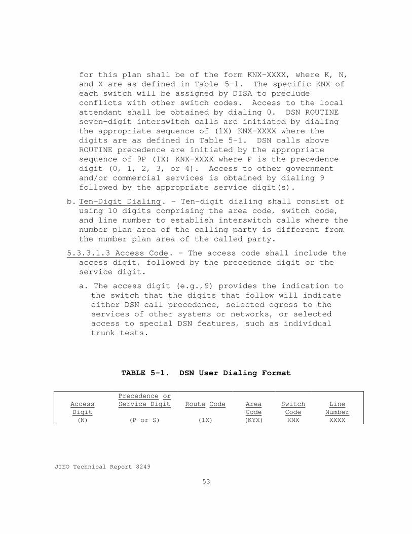
JIEO Technical Report 8249
53
for this plan shall be of the form KNX-XXXX, where K, N,and X are as defined in Table 5-1. The specific KNX ofeach switch will be assigned by DISA to precludeconflicts with other switch codes. Access to the localattendant shall be obtained by dialing 0. DSN ROUTINEseven-digit interswitch calls are initiated by dialingthe appropriate sequence of (1X) KNX-XXXX where thedigits are as defined in Table 5-1. DSN calls aboveROUTINE precedence are initiated by the appropriatesequence of 9P (1X) KNX-XXXX where P is the precedencedigit (0, 1, 2, 3, or 4). Access to other governmentand/or commercial services is obtained by dialing 9followed by the appropriate service digit(s).
b. Ten-Digit Dialing. - Ten-digit dialing shall consist ofusing 10 digits comprising the area code, switch code,and line number to establish interswitch calls where thenumber plan area of the calling party is different fromthe number plan area of the called party.
5.3.3.1.3 Access Code. - The access code shall include theaccess digit, followed by the precedence digit or theservice digit.
a. The access digit (e.g.,9) provides the indication tothe switch that the digits that follow will indicateeither DSN call precedence, selected egress to theservices of other systems or networks, or selectedaccess to special DSN features, such as individualtrunk tests.
TABLE 5-1. DSN User Dialing Format
AccessDigit
Precedence orService Digit Route Code Area
CodeSwitchCode
LineNumber
(N) (P or S) (1X) (KYX) KNX XXXX

JIEO Technical Report 8249
54
Where:
P is any precedence digit 0 - 4 and will be used on rotary-dial or 12-button DTMF keysets.
S is the service digit 5 - 9.K is any digit 2 - 8.N is any digit 2 - 9.Y is the digit 0 or 1.X is any digit 0 - 9.
NOTE: (1) Digits shown in parentheses are not dialed by the DSN user onall calls.(2) The Access Digit plus the Precedence or Service Digitconstitute the Access Code
b. The precedence digit (0, 1, 2, 3, or 4) permits a DSNuser to dial an authorized DSN precedence level fromproperly classmarked 12-button telephone instruments.When the 7-digit intraswitch dialing option is used,it is not necessary to dial or key the precedenceaccess code for ROUTINE calls. The assignment ofprecedence codes is shown in Table 5-2.
c. The service digits, 5 through 9, provide informationto the switch to connect calls to government or publictelephone services or networks that are not part ofthe DSN. The DSN switch will normally collect theaccess code and all routing and address digits beforeattempting to route a call to prevent numberingambiguities between the access codes and the two digitabbreviated dial codes. The assignment of serviceaccess codes is shown in Table 5-2.
5.3.3.1.4 Route Code. - The route code is a special purposeDSN code that permits the customer to inform the switchof special routing or termination requirements. At thepresent time, the route code is used to determine whethera call will use circuit switched data or voice-gradetrunking. It may be used to disable echo suppressers andcancelers, and override satellite link control. It is

JIEO Technical Report 8249
55
not necessary to dial a route code for voice calls if nospecial features are required. The first digit of theroute code is a necessary part of the dialing plan toinform the switch that the next digit, the route digit,gives network instructions for specialized routing. Theroute code assignments are as shown in Table 5 -3.
5.3.3.1.5 Area Code. - The area code indicates thegeographical part of the world or tactical unit(numbering plan area) in which a DSN user is assigned.It is a 3-digit code of the form KYX assigned by DISA andis used only when addressing a user outside of theoriginator's own numbering plan area.
Table 5-2. Precedence And Service Access Codes
1. Assignments for rotary dial, 12-button telephone keysets are:
AccessDigit
PrecedenceDigit
e.g., 9 0 DSN - FLASH OVERRIDE Precedencee.g., 9 1 DSN - FLASH Precedencee.g., 9 2 DSN - IMMEDIATE Precedencee.g., 9 3 DSN - PRIORITY Precedencee.g., 9 4 DSN - ROUTINE Precedence
2. Assignments for Service Access Codes are:
AccessDigit
ServiceDigit
e.g., 9 5 Not Assignede.g., 9 6 Not Assignede.g., 9 7 Not Assignede.g., 9 8 Not Assignede.g., 9 9 Local Public Telephone Network (PTN)
5.3.3.1.6 Switch Code. - The switch code indicates thelocation of a switching center within a numbering plan area.It is a 3-digit code (see Note 1 in Table 5-4) in the form KNXassigned by DISA. This code must be dialed to address anotherswitch in the same numbering plan area.
5.3.3.1.7 Line Number. - The line number is the switchunique DSN user station identification. It is of the form

JIEO Technical Report 8249
56
XXXX. The line number groups cannot be assigned arbitrarilyfor each switch. The line number group assignments must becoordinated with the local connecting telephone company or thehost nation Post, Telephone, and Telegraph (PTT) and withDISA.
Table 5-3. Route Code Assignment
Route Code Route Code Use10 Voice Call (default)
11 Circuit Switched Data
12 Unassigned
13 Unassigned
14 Unassigned
15 Hotline (off-hook) voice grade (switch inserted)
16 Hotline (off-hook) data grade (switch inserted)
17 Unassigned
18 Unassigned
19 Unassigned
5.3.3.2 Intersystem CodesSwitch outpulsing information for Multi-Frequency (MF) 2/6
signaling is shown in Table 5-4.
5.3.3.3 Operator Services Feature InteractionsDSN switches shall meet the requirements in LSSGR Section 5,
paragraph 5.3.3.3.
5.3.4 ScreeningBefore routing a call that is dialed from a user line, the
system shall be capable of determining routing functions fromclass of service information associated with the line. DSNswitches shall be capable of performing screening functions asdescribed in LSSGR Section 5. Paragraph 5.3.4. In additionDSN switches shall be capable of performing the followingscreening functions.
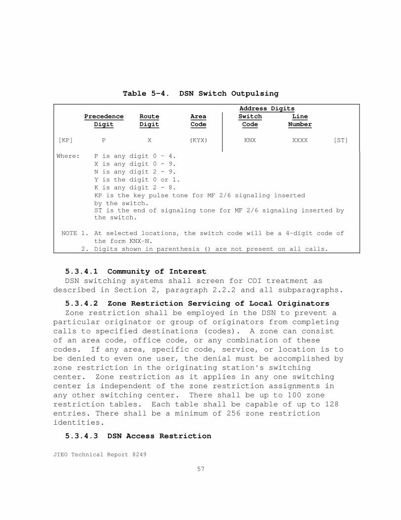
JIEO Technical Report 8249
57
Table 5-4. DSN Switch Outpulsing
Address Digits
[KP]
PrecedenceDigit
P
RouteDigit
X
AreaCode
(KYX)
SwitchCode
KNX
LineNumber
XXXX [ST]
Where: P is any digit 0 - 4.X is any digit 0 - 9.N is any digit 2 - 9.Y is the digit 0 or 1.K is any digit 2 - 8.KP is the key pulse tone for MF 2/6 signaling insertedby the switch.ST is the end of signaling tone for MF 2/6 signaling inserted bythe switch.
NOTE 1.
2.
At selected locations, the switch code will be a 4-digit code ofthe form KNX-N.Digits shown in parenthesis () are not present on all calls.
5.3.4.1 Community of InterestDSN switching systems shall screen for COI treatment as
described in Section 2, paragraph 2.2.2 and all subparagraphs.
5.3.4.2 Zone Restriction Servicing of Local OriginatorsZone restriction shall be employed in the DSN to prevent a
particular originator or group of originators from completingcalls to specified destinations (codes). A zone can consistof an area code, office code, or any combination of thesecodes. If any area, specific code, service, or location is tobe denied to even one user, the denial must be accomplished byzone restriction in the originating station's switchingcenter. Zone restriction as it applies in any one switchingcenter is independent of the zone restriction assignments inany other switching center. There shall be up to 100 zonerestriction tables. Each table shall be capable of up to 128entries. There shall be a minimum of 256 zone restrictionidentities.
5.3.4.3 DSN Access Restriction
JIEO Technical Report 8249
58
Special off-net access lines shall be provided DSN access.Calls arriving over these off-net access lines shall begranted DSN access through an attendant and will be allowedbased on government established administrative procedures.Calls arriving over the DSN for extension to local commercialnetworks or special off-network trunks will also be granted byan attendant based on government administrative procedures.
5.3.4.4 Precedence Signaling.The DSN switch shall be capable of sending and receiving
precedence level digits and route digits. The DSN switchshall also be capable of sending and receiving just theprecedence level digits without the route digits whensignaling to DSN, DRSN, and tactical switches. The DSN switchshall be capable of extending calls to and from trunk and linetype circuits, forwarding the precedence digit and the 10-digit address. Each DSN IST or gateway trunk used in the callpath shall be marked with the precedence level of the call inprogress.
a. The DSN switch shall be capable of Dial Pulse (DP), Dual-Tone Multifrequency (DTMF), Basic Rate Interface (BRI)andPrimary Rate Interface (PRI) Integrated Services DigitalNetwork (ISDN) signaling to support precedence level androute digit for IST and gateway trunk signaling.
b. The DSN switch shall support Multifrequency 2/6 (MF 2/6)and Common Channel Signaling System 7 (CCS7). precedence-level and route-digit signaling
The DSN switch shall be capable of receiving the precedencelevel and route-code digits from the line and propagating thedigits along the call path. The switch shall mark each linewith the precedence level of the call in progress.
5.3.4.5 Private Branch Exchange (PBX) Access LinePreemptionIf an access line is needed to complete a terminating
preempting call, the DSN switch shall:
a. Mark the access line "Preempted for Reuse," release theline and, upon receipt of on-hook signaling, seize theline and outpulse the dialed digits.

JIEO Technical Report 8249
59
b. Send preempt tone to the access line handling the call inprogress to be preempted for either a minimum of 3seconds or continuous tone until a disconnect signal isreceived.
If the access line is not needed to complete the terminatingpreempting call, the DSN switch shall mark the access line"Preempted Not for Reuse," and release the line when adisconnect signal is received.
5.3.4.6 MLPP Interworking With Other NetworksThe precedence level and domain of a call shall not be
changed when interworking with other MLPP networks.
Calls from non-MLPP users that enter a private network thatonly supports MLPP calls shall be assigned a precedence leveland domain identification at the network boundary and may bepreempted within the private MLPP network. The resources ofthe non-MLPP users that exist within the calling network arenot preemptable.
When a precedence call enters a network that does notsupport the MLPP service, the call is treated as an ordinarycall and does not cause preemptions. A network that does notsupport the MLPP service is required, if technically possiblewithin the existing system, to convey the parameters of theMLPP service (e.g., precedence level, domain, etc.) intact.In this case, the network should pass them on with no actiontaken. In other words, the network will not act on theseparameters and pass them on transparently.
5.3.4.7 MLPP Interaction With Other ServicesThe interaction of Custom Local Area Signaling Servces
(CLASS) and other station features with MUFs not specificallyidentified in this GSCR or in the referenced standards shallnot prevent the completion of PRIORITY or higher precedencecalls.
5.3.4.7.1 Call Waiting. - In the case of unavailability ofnetwork resources, the call waiting and MLPP services do notinteract, that is, the preemption of the network resourcestakes place regardless of the state of a call waiting serviceon the call being preempted or the call waiting service being
JIEO Technical Report 8249
60
subscribed to by the intended destination of the precedencecall.
In the case of no lines being available in the access trunkof the called party, the interaction between the invocationsof MLPP and call waiting depends on the relative precedencelevels of the new incoming MLPP call and that of the lowestprecedence MLPP call at the called access as follows:
a. If the precedence level of the incoming call is higherthan that of the existing MLPP call, preemption shalloccur. If the called subscriber is nonpreemptable, callwaiting shall be invoked. If the incoming call isPRIORITY or above, the precedence call waiting tone(Table 6-1) shall be applied to the called party. If theincoming call is ROUTINE, the standard call waiting toneshall be applied to the called party;
b. If the precedence level of the incoming call is the sameas that of the existing MLPP call, call waiting shall beinvoked. If the incoming call is PRIORITY or above, theprecedence call waiting tone (Table 6-1) shall be appliedto the called party. If the incoming call is ROUTINE,the standard call waiting tone shall be applied to thecalled party;
c. If the precedence level of the incoming call is lowerthan that of the existing MLPP call, call waiting shallbe invoked. If the incoming call is PRIORITY or above,the precedence call waiting tone (Table 6-1) shall beapplied to the called party. If the incoming call isROUTINE, the standard call waiting tone shall be appliedto the called party;
Note that the call waiting service may be used by an MLPPsubscriber in combination with the access resources non-preemptable option. In this case, a called user that is busyon an MLPP call shall receive notification of an incominghigher precedence call without the lower precedence call beingpreempted. As a result, the called user may either disconnector place the lower precedence call on hold in order to acceptthe incoming higher precedence call.

JIEO Technical Report 8249
61
5.3.4.7.2 Call Hold. - A held call may be preempted due toa lack of network resources or channels at the held party’sinterface. The call is cleared and the served user, whoinvoked the call hold service, will be notified of thepreemption.
For the case of multiple terminals on an interface, an idlechannel that is reserved for a call held by another terminalmay be seized in order to complete a higher precedence call.In addition, an active channel that is reserved for a heldcall may be preempted and seized in order to complete a higherprecedence call. In both cases, the held call is not lost andmay be retrieved when a channel becomes available.
5.3.4.7.3 Call Forwarding To a Busy Station. If theincoming call is of higher precedence level than theestablished call (or calls if three way calling isestablished) at the busy station, all calls to the busystation being called will be preempted and the incoming callwill be established, i.e., the call forwarding service willnot be invoked.
If the incoming call is of equal or lower precedence levelthan the established call, (or calls if three way calling isestablished) at a busy station, the call-forwarding servicewill be invoked.
If the called C2 user, special C2 user, or other DSN user isnonpreemptable (is not classmarked for preemption), the callforwarding service will be invoked regardless of theprecedence levels of incoming calls and established calls.
The precedence level of calls is preserved during theforwarding process, and the forwarded-to user may bepreempted.
If call forwarding busy is activated by the called party andthe called party has specified an alternate party, theforwarding procedure will be performed prior to the alternateparty diversion. If a precedence call is forwarded and is notresponded to by any forwarded-to party within a specifiedperiod of time, typically 30 seconds, the call will bediverted to the specified alternate party. If an alternateparty is not specified, and the forwarded-to party does not

JIEO Technical Report 8249
62
respond, the call will be routed to a programmed precedencelevel deflection station number. If a deflection stationnumber has not been specified, or if the deflection stationnumber does not answer, the call will be routed to anattendant.
5.3.4.7.4 Call Forwarding - No Reply at Called Station .The precedence level of calls are preserved during theforwarding process, and the forwarded-to user may bepreempted. Unanswered precedence calls will be diverted tothe alternate party if that option is subscribed to by thecalled user. If an alternate party is not specified and callforwarding is not responded to by the forwarded-to party, thecall will be routed to a programmed precedence leveldeflection station number or, if none was specified or if thedeflection station number does not answer, to an attendant.
5.3.4.7.5 Call Transfer. For a normal call transfer, theprecedence level of calls is preserved during the transferprocess. For an explicit call transfer, when two calls areinvolved, each connection of the transferred call maintainsthe precedence level that it was assigned when that connectionof the call was established. Thus, a call that is establishedthrough an explicit call transfer may consist of twoconnections at different precedence levels.
5.3.4.7.6 Conference Calling. All connections to theconferees are processed at a precedence level equal to theconference precedence level selected by the conferencecontroller for all connections to conferees on the conferencecall. If a conferee is preempted, the conference controlleris notified of the preemption. When the controller ispreempted, all conferees are notified and the procedure isfollowed as though the controller issued a "disconnect"request. Each connection of a call, resulting from a splitoperation, will maintain the precedence level that it wasassigned upon being added to the conference call.
5.3.4.7.7 Circular Line Hunting. Circular line huntingshall be implemented so that if no line is available and oneor more existing calls are of lower precedence level than thatof the incoming call, an existing call of the lowestprecedence level shall be preempted.

JIEO Technical Report 8249
63
5.3.4.7.8 Three-Party Service. In minimal three-partyservice, each call will have its own precedence level. When athree-way conversation is established, each connectionmaintains its assigned precedence level. Each connection of acall resulting from a split operation, shall maintain theprecedence level that it was assigned upon being added to thethree-way conversation.
5.3.4.8 Attendant CallsIncoming DSN precedence calls to the attendant's listed
directory number and incoming calls diverted to an attendantshall signal the attendant by a distinctive, visual signalindicating the precedence level and shall be placed in queue.
5.3.4.9 Precedence Calls to a Remote OfficeThe DSN switch shall have the capability of extending calls
addressed to a remote switch over access lines to that switchon a modified Precedence Network Inward Dial (PNID) basis.With this modified PNID operation, calls with a precedencelevel higher than ROUTINE shall be initially extended to theremote switch. The serving switch shall provide precedenceringback to the calling party and monitor the access line tothe remote switch for busy signal and answer supervision. Ifa busy signal is received or answer supervision is notreceived within an adjustable time period of 15 to 45 seconds,the serving switch shall divert the call to the servingattendant. If answer supervision is received within the time-out interval, the serving switch shall remove the ringbacktone and cut-through. An option shall be provided to divertthe call to an appropriate recorded announcement in lieu ofthe attendant. The modified PNID operation shall beselectable on a trunk group basis through the use of aterminating classmark.
5.3.5 RoutingRouting on DSN switching systems shall comply with LSSGR
Section 5, paragraph 5.3.5 and it subparagraphs except asmodified in the following paragraphs.
5.3.5.1 Outgoing CallsLSSGR, Section 5, paragraph 5.3.5.2 is modified to read:
“The system shall permit assignment of at least nine

JIEO Technical Report 8249
64
additional TGs as alternate routing paths for the destinationcode requested.
LSSGR, Section 5, paragraph 5.3.5.2.B.1, InterLATA Calls, isan optional requirement that can be specified in site specificcontracts.
LSSGR, Section 5, paragraph 5.3.5.2.B.3 Transitional RouteArrangement, is an optional requirement the can be specifiedin site specific contracts.
5.3.5.2 Corridor CallsLSSGR, Section 5, paragraph 5.3.5.5, Corridor Calls does not
apply to DSN switching systems.
5.3.5.3 Primary and Alternate RoutesDSN switches shall be capable of providing call connections
over a primary route and nine (9) alternate routes to a DSNdestination. Each route shall have the capability ofincluding a minimum of four (4) trunk groups or sub-trunkgroups for separately grouping various categories of trafficsuch as voice, data, satellite , and terrestrial transmission.Gateway switches shall be dual homed with alternate routes.
5.3.6 Outpulsing Code FormulationOutpulsing code formulation shall be accomplished in
accordance with LSSGR, Section 5, paragraph 5.3.6.
5.3.7 Trunk Selection (Hunting)Trunk selection shall be performed in accordance with LSSGR,
Section 5, paragraph 5.3.7 and its subparagraphs. Inaddition, route shall be capable of including both voice-gradeand data-grade trunk groups. The hunting sequence shall becapable of being varied depending on the route. Huntsequences shall be capable of scanning data-grade trunk groupsfor voice-grade calls. The hunting sequence shall be capableof searching all trunks. The hunting sequence shall firstexamine the route digit so that, for data calls only, data-grade trunks will be searched and provide treatments such asecho canceller suppression. For voice-grade calls, all trunkswill be searched.

JIEO Technical Report 8249
65
5.3.7.1 Hunt Sequence for Classmarked TrunksWhen the MFS provides a classmarked trunk to a DSN EO, the
MFS shall provide the hunt sequence defined below. The MFSshall route calls to classmarked trunks that have classmarksto indicate the precedence level and calling area (PL/CA).Calls shall not be completed over trunks that are classmarkedat a PL/CA authorization lower than that used to originate thecall. The hunt sequence is shown in Figure 5-1 where CA isdefined as one of five progressively wider CAs (A1, A2, A3,A4, A5) and PL is defined as one of five PLs (PL0 = FLASHOVERRIDE, PL1 = FLASH, PL2 = IMMEDIATE, PL3 = PRIORITY, andPL4 = ROUTINE. For calls above ROUTINE, the preemptive search,as shown in Figure 5-1, shall begin on the primary route andthe proceed, if necessary, on all programmed alternate routes.
5.3.7.1.1 ROUTINE Calls. For ROUTINE calls, the switchshall employ a friendly search for an idle trunk on allprogrammed routes to the call destination. Failing to find anidle trunk, the switch shall provide a trunk busy tone to thecaller.

JIEO Technical Report 8249
66
PL = Dialed Precedence LevelCA = Dialed Calling Area
Hunt for IDLE Classmarked IST for PL and CA
Does CAoffer maximumpossible calling
area?
Does PLequal maximum
possibleprecedence level?
IS this aROUTINE
Call?
Hunt for Classmarked IST classmarkedfor PL and CA that is busy with the lowestprecedence call of lower precedence levelthan the dialed precedence level
Does CAequal maximum
possiblecalling area?
Does PLequal maximum
possibleprecedence level?
BLOCKED PRECEDENCE ANNOUNCEMENT
Returned to call originator
PL = PL +1CA = Dialed Calling Area
CA = CA + 1
TRUNK BUSY TONEReturned to call originator
PL = PL +1CA = Dialed Calling Area
CA = CA + 1
Succeed
Fail
No
Yes
No
Yes
Yes
No
Succeed
Fail
No
Yes
No
Yes
PreemptRoute Call
Route call
PreemptiveSearch
Figure 5-1. Hunt Sequence for Classmarked ISTs

JIEO Technical Report 8249
67
5.3.7.1.2 Precedence Calls Above ROUTINE. The switch shallbe capable of being programmed for two methods of trunk routeselection for precedence calls above ROUTINE. The method usedshall be based on the route being searched and the KYX and/orKNX code dialed. In all methods, trunks shall be individuallytested for idle or busy conditions. If preemption isrequired, only a call of the lowest level of precedence lowerthan the dialed precedence shall be preempted.
1. In the first method, the switch failing to find anidle trunk in the direct route, or any of the programmedalternate routes for a precedence call, shall enter thepreemptive search. In the preemptive search, the switch shalltest the trunks, one by one, to determine if there are anyidle trunks in the direct route, and if so, shall select anyidle trunk in the direct route. If no idle trunks exist, theswitch shall preempt the call of the lowest precedenceobserved during the idle trunk search, provided the precedenceof the call selected for preemption is lower than theprecedence of the call being processed. Failing to completethe call on the direct route, the switch shall advance thepreemptive search to the first alternate route, and repeat theprocess described above. When the switch is unable topreempt, it shall route a Blocked Precedence Announcement(BPA) to the caller. The switch shall be capable of varyingthe number of alternate routes searched based on the incomingroute and the codes dialed.
2. In the second method, the switch shall search for anidle trunk in the direct route on a friendly basis, and thenon a preemptive basis, if no idle trunk is found on thefriendly search. Failing to complete the call on the directroute will cause the first alternate route to be searchedfirst on a friendly basis, and then preemptively. Thisprocess shall be repeated for all subsequent routes. When theswitch is unable to preempt, it shall route a BPA to thecaller. The switch shall be capable of varying the number ofalternate routes searched based on the incoming route and thecodes dialed.
JIEO Technical Report 8249
68
5.3.8 Internal Overload ControlDSN switching systems shall perform internal overload
controls in accordance with LSSGR Section 5, paragraph 5.3.8and its subparagraphs.
5.3.9 Essential Service Protection (ESP)ESP shall be provided in accordance with LSSGR Section 5,
paragraph 5.3.9,.
5.3.10 Automatic Message Accounting (AMA)AMA shall be provided in accordance with LSSGR section 5,
paragraph 5.3.10.
5.4 Switch Processing TimeDSN switching systems processing times shall be in
accordance with LSSGR Section 5.6, GR-1364-CORE.
5.5 DSN Routing and Numbering
5.5.1 GeneralReference c establishes a standard numbering system that
serves all DSN users throughout the world in a uniform manner.The system includes area and switch codes assigned foraccessing the DRSN, U.S. tactical switches, and the NorthAtlantic Treaty Organization (NATO) IVSN. The capability tooperate with the DSN NP and the North American Numbering Plan(NANP) shall be incorporated in all new DSN switchesintroduced into the DSN.
5.5.2 Standard Directory NumbersStandard directory numbers for the services listed in
Table 5-5 shall adhere to the format and assignments specifiedand will allow a network call to reach that service.
5.5.3 Standard Test NumbersStandard test numbers for test and maintenance capabilities
shall adhere to the format and number assignments listed inTable 5-6.
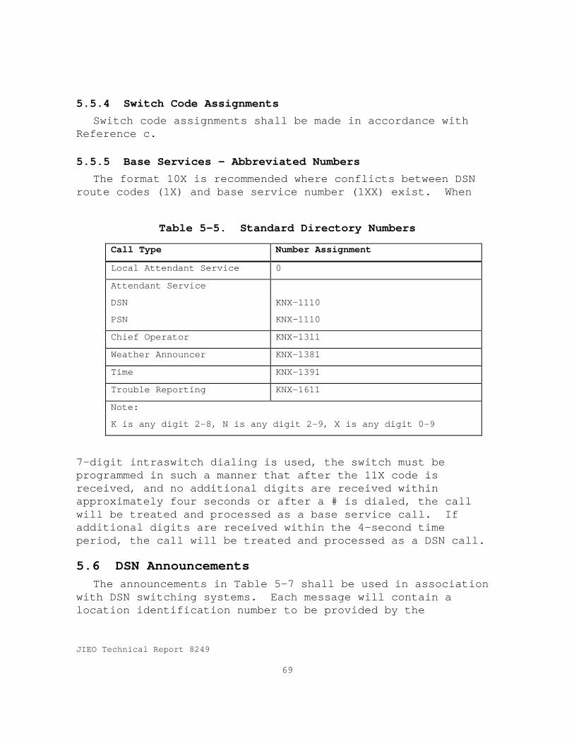
JIEO Technical Report 8249
69
5.5.4 Switch Code AssignmentsSwitch code assignments shall be made in accordance with
Reference c.
5.5.5 Base Services - Abbreviated NumbersThe format 10X is recommended where conflicts between DSN
route codes (1X) and base service number (1XX) exist. When
Table 5-5. Standard Directory Numbers
Call Type Number Assignment
Local Attendant Service 0
Attendant Service
DSN
PSN
KNX-1110
KNX-1110
Chief Operator KNX-1311
Weather Announcer KNX-1381
Time KNX-1391
Trouble Reporting KNX-1611
Note:
K is any digit 2-8, N is any digit 2-9, X is any digit 0-9
7-digit intraswitch dialing is used, the switch must beprogrammed in such a manner that after the 11X code isreceived, and no additional digits are received withinapproximately four seconds or after a # is dialed, the callwill be treated and processed as a base service call. Ifadditional digits are received within the 4-second timeperiod, the call will be treated and processed as a DSN call.
5.6 DSN AnnouncementsThe announcements in Table 5-7 shall be used in association
with DSN switching systems. Each message will contain alocation identification number to be provided by the

JIEO Technical Report 8249
70
Government. The switching system will be as “Switch Name andLocation.”
Table 5-6. Standard Test Numbers
Call Type Number AssignmentMilliwatt Test KNX-1021Supervisory and Signal Test KNX-1031Far End Transmission and Noise Test KNX-1041Dial Speed Test KNX-1351DTMF Test KNX-1361Ringback Test KNX-1371Line Check Test KNX-1301Loop Around Termination KNX-1061Preemption Test KNX-1071Note:K is any digit 2-8, N is any digit 2-9, X is any digit 0-9
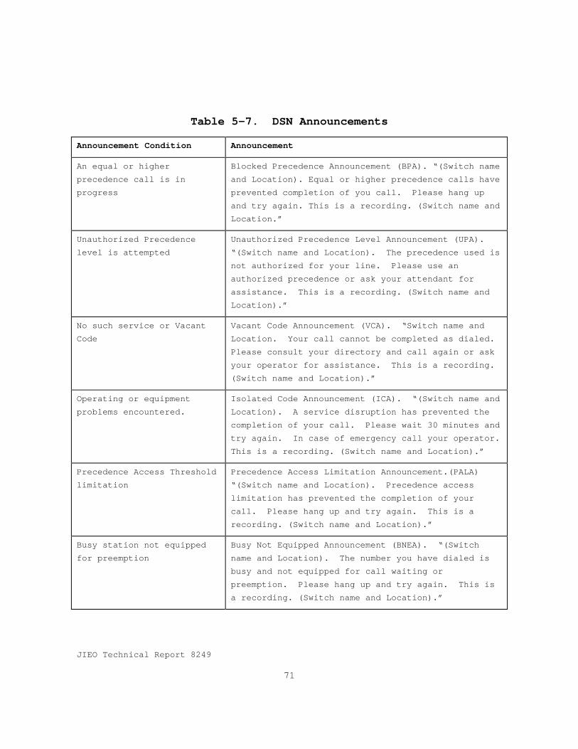
JIEO Technical Report 8249
71
Table 5-7. DSN Announcements
Announcement Condition Announcement
An equal or higherprecedence call is inprogress
Blocked Precedence Announcement (BPA). “(Switch nameand Location). Equal or higher precedence calls haveprevented completion of you call. Please hang upand try again. This is a recording. (Switch name andLocation.”
Unauthorized Precedencelevel is attempted
Unauthorized Precedence Level Announcement (UPA).“(Switch name and Location). The precedence used isnot authorized for your line. Please use anauthorized precedence or ask your attendant forassistance. This is a recording. (Switch name andLocation).”
No such service or VacantCode
Vacant Code Announcement (VCA). “Switch name andLocation. Your call cannot be completed as dialed.Please consult your directory and call again or askyour operator for assistance. This is a recording.(Switch name and Location).”
Operating or equipmentproblems encountered.
Isolated Code Announcement (ICA). “(Switch name andLocation). A service disruption has prevented thecompletion of your call. Please wait 30 minutes andtry again. In case of emergency call your operator.This is a recording. (Switch name and Location).”
Precedence Access Thresholdlimitation
Precedence Access Limitation Announcement.(PALA)“(Switch name and Location). Precedence accesslimitation has prevented the completion of yourcall. Please hang up and try again. This is arecording. (Switch name and Location).”
Busy station not equippedfor preemption
Busy Not Equipped Announcement (BNEA). “(Switchname and Location). The number you have dialed isbusy and not equipped for call waiting orpreemption. Please hang up and try again. This isa recording. (Switch name and Location).”


JIEO Technical Report 8249
73
Section 6
Signaling
6.1 GeneralThis section contains the signaling requirements for DSN
switching systems. It is based on the Bellcore LSSGR, Section6. The LSSGR uses the words “should” and “shall” to indicaterequirements. The word “should” in the LSSGR is interpretedas “shall” for the purposes of DSN GSCR.
6.1.1 Battery Supplies and Internal ResistanceDSN switching systems shall meet the battery supplies and
internal resistance’s requirements specified in the BellcoreLSSGR, Section 6, paragraph 6.1.1 and its subparagraphs.
6.2 Customer Line SignalingDSN switching systems shall meet the customer line signaling
requirements specified in the Bellcore LSSGR Section 6,paragraph 6.2 and its subparagraphs except for DTMF signals inparagraph 6.2.6.2.A. Requirements for multi-party service andcoin services are not applicable to DSN.
6.3 In-Band SignalingDSN switching systems shall meet the in-band signaling
requirements specified in DISA Circular 370-175-13, DSN SystemInterface Criteria.
6.3.1 Preempt SignalingPreemption shall be accomplished at the preempting switching
center by sending a measured supervisory signal toward boththe calling and called stations. The supervisory pulses shallbe recognized at each switch, causing disconnect of theintermediate trunk circuits and the line circuits at each end.Following circuit release, a preempt tone of 440 + 620 Hzshall be applied to each end-station. The preempt tones shallbe introduced at a composite level of -16 dBm, measured at thezero transmission level point (TLP), and shall be maintained
JIEO Technical Report 8249
74
until a disconnect signal is returned to the switching system.The trunk or line which was selected for preemption is nowreused to serve the waiting precedence call. The preemptsignals used in the DSN are shown in Figure 6-1. Four preemptsignals exist depending upon the on-hook or off-hook conditionof the circuit and the intended disposition. A completedescription of the preempt signaling can be found in DISACircular 370-175-13.
6.4 Control SignalingDSN switching systems shall meet the control signaling
requirements specified in DISA Circular 370-175-13. Audibletones shall be in accordance with Bellcore LSSGR, Section 6,Table 6.4-C, and Table 6-1. Tone signals in Table 6-1 may besubstituted with other COTS signals provided that suchsubstitution results in a unique indication associated withthe identified function.
6.5 Common Channel Signaling Number 7CCS7 shall be in accordance with Bellcore LSSGR Section 6,
paragraph 6.5.1 and all its subparagraphs. Section 6 of theBellcore LSSGR is an implementation of the ANSI T1.100 seriesof standards. Exceptions to these standards are explicitlynoted in this section. DSN End Office, Multi-Function, andTandem switching systems shall be CCS7 Signaling Points (SP).
6.5.1 OverviewCCS7 shall be in accordance with Bellcore LSSGR, Section 5,
paragraph 6.5.1 which is compatible with the U.S. nationalsignaling system No. 7 (SS7) networks based on the mostcurrent ANSI T1.100 series of standards and shall be capableof interworking ITU-T signaling system No. 7 (SS7)networks.

JIEO Technical Report 8249
75
Figure 6-1. DSN Preempt Signals
328 - 363 ms
Off-Hook
On-Hook
Answered Call; circuit to be reused.
Off-Hook
On-Hook95 - 105 ms
Unanswered call; circuit to be reused.
Answered call; circuit not to be reused.
Unanswered call; circuit not to be reused .
328 - 363 ms
Off-Hook
On-Hook95 - 105 ms
328 - 363 ms
95 - 105 ms95 - 105 ms328 - 363 ms
Off-Hook
On-Hook

JIEO Technical Report 8249
76
Table 6-1. DISN Information Signals for EO and PBX
Signal Frequencies
(Hz)
Single Tone
Level
Composite
Level
Interrupt
Rate
Tone On Tone Off
Audible Ringback
Precedence Call
440+ 480
(Mixed)
-13 dBM0 -16 dBm0 13 Impulses
per minute
(IPM)
1640 ms 360 ms
Preemption Tone 440 + 620
(Mixed)
-13 dBM0 -16 dBm0 Steady On
Call Waiting
(Precedence Call)
440 -13 dBm0 6 IPM 100 ± 20
ms Three
Bursts
9700 ms
Conference Disconnect
Tone
852 and 1336
(Alternated at
100 ms
intervals)
-24 dBm0 Steady On 2000 ms (per occurance)
Call Forwarding 350 + 440
(Mixed)
-13 dBm0 -10 dBm0 Three bursts 100 ms ON 100 ms OFF then
steady 0N
Override Tone 440 6 IPM 2000 ms (followed by)
500 ms ON 7500 ms OFF
Camp On 440 -13 dBm0 Single Burst 0.75 to 1
second
Alerting (Ringing) Normal or Routine Call
4-Wire Line 2-Wire
Line
20 86V RMS 10 IPM 2000 ms 4000 ms
Alerting (Ringing) Precedence Call
4-Wire Line 2-Wire
Line
20 86V RMS 30 IPM 1640 ms 360 ms
Conference
Notification Tone
852 and 1336 -24 dBm0 Alternate at 300 ms intervals
6.5.1.1 CCS7 Network Structure.The CCS7 network shall serve as a separate call control and
management network that is overlaid on the DSN. The CCS7network structure is a one-level hierarchy composed ofmultiple mated pairs of Signal Transfer Points (STP) and their

JIEO Technical Report 8249
77
associated Signaling Points (SP) and signaling links inaccordance with ANSI T1.115.5. The CCS7 network structure isshown in Figure 6-2. The CCS7 network consists of mated STPpairs connected by “C-Links”, these mated pairs may be groupedinto “quads” with “B-Links”. STPs may be implemented externalto the switches. The CCS7 design, including the number ofSTPs, links and locations, shall be provided by DISA.
STPs will host both ANSI/Bellcore GR-246-CORE and ITU-TRecommendations Q.700 - Q.716 link sets. STP’s will alsoimplement Gateway Screening IAW Bellcore specification GR-82-CORE, Signal Transfer Point Generic Requirement, 1996. TheGateway Screening feature controls access to non-CCS7networks, (i.e., LEC and IC networks).
6.5.1.2 CCS7 Network AccessDSN switching systems shall access the CCS7 network as
described in the following paragraphs.
6.5.1.2.1 Signaling Links. CCS7 signaling links connectnetwork signaling elements in a signaling network. Thesignaling links encompass the level 2 functions specified inANSI T1.111.3.
a. “A-Links” are the primary access signaling links thatconnect SPs (switching systems) to an STP.
b. “B-Links” connect mated pairs of STPs into quads toprovide redundancy and reliability in the signalingnetwork.
c. “C-Links” connect two STPs into a mated pair.
d. “E-Links” connect a SP (DSN switch) to a remoted STP.
e. “F-Links” connect two SPs.
6.5.1.2.2 Signaling Points. All DSN switching systems shallbe a SP.
a. CCS7 SPs are origination, and destination points forsignaling messages.

JIEO Technical Report 8249
78
Figure 6-2. CCS7 Backbone Network Architecture
C Link Between Mated STP Pairs
B Link Connecting 2 Sets of Mated STP Pairs
A Link
E Link
F Link
Signal Transfer Point (STP)
Signaling Poing
b. As a minimum each SP shall be assigned a uniquesignaling point code for addressing signaling messages.All DSN switching systems shall have the Multiple PointCode Capability IAW with Bellcore LSSGR Section 6,paragraph 6.5.1.4
6.5.1.2.3 Signal Transfer Point (STP). The STP serves asthe transfer point for CCS7 signaling messages. STPs shallmeet Bellcore GR-82-CORE, 1996 requirements.
JIEO Technical Report 8249
79
6.5.1.3 CCS7 ProtocolCCS7 shall meet the protocol requirements stated in Bellcore
LSSGR, Section 6, paragraph 6.5.1.3.
6.5.1.4 Multiple Point Code CapabilityDSN switching systems shall provide the multiple point code
capability as described in the Bellcore LSSGR, Section 6,paragraph 6.5.1.4.
6.5.1.5 Numbering of Signaling Point CodesThe CCS7 numbering of signaling point codes shall be as
specified in ANSI T1.111.8. The DSN meets the ANSIrequirements for a large network and has been granted anetwork code value of 241.
6.5.2 Signaling Link Characteristics.DSN switching systems shall meet the requirements in the
Bellcore LSSGR, Section 6, paragraph 6.5.2 and itssubparagraphs. In addition, the following requirements shallbe met.
6.5.2.1 Error Detection and RecoveryIn addition to the basic error detection requirements in
LSSGR, Section 6. Paragraph 6.5.2.4, DSN switching systemsshall use the Preventive Cyclic Retransmission (PCR) ErrorCorrection method when a satellite path is used in a combinedlink. PCR may also be used for terrestrial links in regionswhere a satellite path is used as an alternate route.
6.5.3 Message Signal Unit Information HandlingDSN switching systems shall meet the Message Signal Unit
Information Handling requirements in the Bellcore LSSGR,Section 6, paragraph 6.5.3 and all its subparagraphs except asmodified below.
6.5.3.1 Routing LabelCCS7 shall use the U.S. national label structure as
specified in Bellcore LSSGR Section 6, paragraph 6.5.3.1 whichis in accordance with ANSI T1.111.4. The network clustermember subfield is assigned by the CCS7 Network Administratorto identify individual SP and STPs.

JIEO Technical Report 8249
80
CCS7 shall use the 8-bit SLS field in accordance withBellocre LSSGR, Section 5, paragraph 5.3.4.
6.5.4 Signaling Network ManagementDSN switching systems shall meet the Signaling Network
Management requirements in the Bellcore LSSGR, Section 6,paragraph 6.5.4 with the following exceptions.
6.5.4.1 Signaling Link ChangebackDSN switching systems shall not use sequence control
procedures to perform changeback. The last sentence of thethird requirement in the Bellcore LSSGR, Section 6, paragraph6.5.4.3 is changed to read as follows:
“The SPCS shall use the time-controlled diversionprocedure.”
6.5.4.2 Signaling Network CongestionIn addition to the congestion control requirements in the
Bellcore LSSGR, section 6, paragraph 6.5.4.8, DSN signalinglinks and signaling link sets determine the network's overalloperability during network element congestion. Criteria forthe determination of CCS7 signaling congestion status shall beas specified by ANSI T1.111.4, section 3.8 for U.S. networks.In case of congestion, Initial Address Messages (IAMs)carrying FLASH or FLASH OVERRIDE calls shall be assigned thehighest level, IMMEDIATE and PRIORITY calls shall beassigned mid-level, and ROUTINE calls shall be assigned lowestlevel.
6.5.5 Noncircuit-Related Information Exchange - SignalingConnection Control Part (SCCP)
DSN switching systems shall meet the SCCP requirements inthe Bellcore LSSGR, Section 6, paragraph 6.5.5 and itssubparagraphs.
6.5.6 Additional Procedures for Switch-to-Switch/SCP TCAPMessages
DSN switching systems shall meet the requirements forswitch-to-switch/SCP TCAP requirements in the Bellcore LSSGR,Section 6, paragraph 6.5.6 and its subparagraphs.

JIEO Technical Report 8249
81
6.5.6.1 Transaction Capability Application Part (TCAP) -Definitions and Functions of Transaction Capability (TC)Operations, Parameters, and Error Codes.The CCS7 functions and encoding for the Operation, Parameter
and Error Code elements used by the TCAP protocol shall be asspecified in ANSI T1.114.5.
6.5.7 Circuit-Related Information ExchangeDSN switching systems shall meet the requirements for
Circuit-Related Information Exchange in the Bellcore LSSGR,Section 6, paragraph 6.5.7 and its subparagraphs.
6.5.8 Switch CapacityThe link/terminal capacity of a DSN switching system, as
well as the memory capacity, shall be sufficient to allow forup to 72 signaling links for direct routing of A-, E-, and F-links as well as backup routing for all links. DSN networkmanagement personnel shall be provided the capability toengineer normal and alternate link sets to handle the totalmessage traffic.
6.5.9 PerformanceThe DSN switch CCS7 systems shall meet the requirements and
objectives stated in the Bellcore LSSGR, Section 6, paragraph6.5.9 and its subparagraphs.
6.5.10 CCS7 Message FormattingDSN CCS switching system shall use the message formatting
described in the Bellcore LSSGR, Section 6, Appendix A withthe following modifications
6.5.10.1 Message Signaling Unit (MSU) Service Information.Bellcore LSSGR, Section 6, Appendix A, paragraph A.2E,
Service information octet is modified as follows:
a. Service Indicator. A listing of the service indicatorcodes and their current CCS7 implementation status isshown in Table 6-2.

JIEO Technical Report 8249
82
b. Subservice Fields. - The CCS7 shall use the network code(10) as specified in ANSI T1.111.4. CCS7 messagesoriginating and terminating within the CCS7 or anothernetwork conforming to the ANSI standard shall also becoded with the national network code (10).
c. Message Priority. - Priority 3 is the highest messagepriority code and is reserved for network management andother messages critical to the performance of the MTP.Assignment of priority levels to other messages and userparts shall be in accordance with the DSN-specificguidelines. DSN priorities shall not be changed if aCCS7 call must cross the network boundaries. However, itis subject to bilateral agreements negotiated with othernetwork providers. The CCS7 Network Administrator shallhave the ability to assign and change priority levels formessages of specific user parts within the CCS7 and toagree with interconnecting networks for messages thatenter and leave the DSN.
6.5.11 CCS7 ISDN User Part (IS-UP)The IS-UP specifies the signaling functions, codes, and
procedures needed to provide services for circuit-switchedvoice and data services. CCS7 switching services shall meetthe requirements in the Bellcore LSSGR, Section 6, SwitchingSystem Generic Requirements for Call Control Using theIntegrated Services Digital Network User Part, GR-317-CORE,except as modified in the following subparagraphs.
6.5.11.1 IS-UP MessagesCCS7 shall use the messages in the Bellcore LSSGR, Section
6, GR-317-CORE, Appendix A. In addition, CCS7 shall meet therequirements in ANSI T1.113.2 and T1.619a for messages whichare not specified in the Bellcore generic requirements.
6.5.11.2 IS-UP ParametersCCS7 shall use the IS-UP parameters specified in the
Bellcore LSSGR, Section 6, GR-317-CORE, Appendix B, except asmodified below. In addition, CCS7 shall use IS-UP parametersspecified in ANSI T1.113.3 for parameters not specified in theBellcore requirements.

JIEO Technical Report 8249
83
6.6 DSN ISDN User to Network Signaling.The objective of this DSN ISDN user-to-network signaling
specification is to provide digital out-of-band signaling onan ISDN interface. The DSN ISDN user-to-network signalingspecification, which captures protocols under the umbrella ofDigital Subscriber Signaling System No. 1 (DSS1), is intendedto provide a signaling protocol that will allow signaling overan ISDN interface to support:
Table 6-2. Service Indicator Codes
D C B A CCS70 0 0 0 Signaling network management messages YES0 0 0 1 Signaling network testing and maintenance regular messages YES0 0 1 0 Signaling network testing and maintenance special messages YES0 0 1 1 SCCP YES0 1 0 0 Telephone User Part NO0 1 0 1 ISDN User Part YES0 1 1 0 Data User Part (call and circuit related messages) NO0 1 1 1 Data User Part (facility registration and cancellation messages)
NO1 0 0 0 MTP Testing User Part YES1 0 0 1 Spare1 0 1 0 Spare1 0 1 1 Spare1 1 0 0 Spare1 1 0 1 Reserved for DSN only use1 1 1 0 Reserved for DSN only use1 1 1 1 Spare
a. User access to DSN switches equipped with the CCS7.b. Circuit-switched (CS) calls (both data and voice).c. Supplementary services that include unique DSN features.d. Future DSN access signaling requirements for other
network services, including public and private networkinterworking in intra- and inter-country environments, asapplicable, and interoperability with other DoD Networks.

JIEO Technical Report 8249
84
6.6.1 ApplicationThis section is the DSN switch standard for user-to-network
signaling over an ISDN interface. It specifies the interfacesignaling protocol for application throughout the DSN anddefines the requirements of the DSN user-to-network signalingfor exchanging information between customer premises equipment(CPE), including terminal equipment (TE) and PBXs, and DSNnetwork switches. The exchange of signaling information CPEand DSN network switches shall be over the D-channel of theISDN interface. The D-channel may be used either forassociated signaling or non-associated signaling as defined inAnnex F of American National Standards Institute (ANSI)T1.607. In-band information and tones sent over the B-channelshall be allowed, when applicable. In the DSN host countries,DSN connections may be made with public, private, and militaryCPE and networks. Protocol and/or signaling gatewayconversions shall be required in some instances to provide thedesired DSN connections. Such translations shall be handledon a case-by-case basis as detailed in site specificcontracts.
6.6.2 Related specificationsThis paragraph and paragraph 6.5 (CCS7) in combination with
MIL-STD-188-194 and ANSI T1.619a form a complete set ofspecifications for the CCS7.
6.6.3 CompatibilityThis specification is aligned with the ANSI standards. The
International Telecommunications Union (ITU) recommendationsare used when necessary details (for outside Continental U.S.(OCONUS) applications) are not available in the ANSIstandards. The DSN user-to-network signaling shall conform tothe requirements of the ANSI standards, except for uniquerequirements of DSN features as specified in this GSCR.
6.6.4 Physical Layer.The DSN user-to-network signaling physical Layer
specification for the basic rate interface shall be ANSIT1.605 and ANSI T1.601 or ITU Recommendation I.430 as required
JIEO Technical Report 8249
85
for OCONUS applications. The DSN user-to-network signalingphysical layer specification for the primary rate interfaceoperating at 1.544 megabits per second (Mbps) shall be ANSIT1.408. The DSN user-to-network signaling specification forthe primary rate interface operating at 2.048 Mbps shall beITU Recommendation I.431.
6.6.4.1 S/T Reference PointFor the basic rate interface at the S/T reference point,
B-channels shall have the capability of either restricted orunrestricted operation. The restricted capability isnecessary for backward compatibility with networks thatsupport the restricted 64 kbps operation. The D -channel shallhave unrestricted capability.
6.6.4.2 Line CodeFor the 1.544 Mbps primary rate interface, the DSN user-to-
network signaling shall utilize the bipolar with 8-zerosubstitution (B8ZS) line code, except where the followingspecial arrangements for maintaining a satisfactory density of1s is made:
a. By agreement between the DSN Network Administrator andthe user, a method referred to as zero byte time slotinterchange (ZBTSI) may be used to assure the necessary1s density in the access channel. The ZBTSI format isspecified in the rates and formats standards (ANSIT1.107).
b. Because much of the existing equipment in the DSN isequipped to handle the alternate mark inversion (AMI)line code, it may be utilized in the transition perioduntil the B8ZS line code is implemented network wide.
6.6.5 Data-Link Layer.The DSN user-to-network signaling data-link layer shall be
as specified in the ANSI T1.602, ISDN - Data-Link LayerSignaling Specification for Application at the User-NetworkInterface, which is a pointer document completely aligned withthe ITU-T Recommendations Q.920 and Q.921.

JIEO Technical Report 8249
86
6.6.5.1 Data-Link ConnectionsPoint-to-point, broadcast, and multipoint data-link
connections shall be provided for DSN applications. The ANSIT1.602 depicts examples of point-to-point and broadcast data-link connections. Other point-to-point applications of thisspecification shall be allowed, such as the support ofmultiple terminals at the user-to-network interface. A data-link layer management entity shall be provided to support DSNmanagement.
6.6.5.2 Peer-to-Peer Procedures of the Data-Link LayerWithin the DSN, peer-to-peer procedures of the data-link
layer shall follow the procedures described in the ANSIT1.602, with the additions provided in this paragraph. TheNetwork Administration shall have the responsibility todetermine the system parameter values on the DSN user-to-network interface. These parameters shall initially be set tothe default values of the ANSI standard. A means is availablein Appendix IV of Q.921 to change the assignment of the systemparameters within the range of values specified by the ANSIstandard. DSN terminal equipment shall support other valuesof T200 to allow for multiple terminals on the user side,together with satellite connections in the DSN user-to-networktransmission.
6.6.6 Layer 3 DSN User-to-Network SignalingThe layer 3 protocols specify the messages and information
elements, coding and formats, and procedures employed on theuser-to-network interface in order to establish, maintain, andterminate network connections across an ISDN.
6.6.6.1 Layer 3 - Overview of Layer 3.The overview of layer 3 of the DSN user-to-network signaling
layer 3 shall be as specified in the ANSI T1.615. The ANSIstandard is consistent with the seven-layer model described inITU Recommendation I.320. ANSI T1.615 describes, in generalterms, the D-channel layer 3 DSS1 functions and protocolemployed across an ISDN user-to-network interface.
JIEO Technical Report 8249
87
6.6.6.2 DSN User-to-Network Signaling for Circuit-Switched (CS) Bearer ServiceThe DSN user-to-network signaling layer 3 specification for
CS bearer service (or CS-Basic Call) shall be as specified inthe ANSI T1.607 for ISDN primary and basic rate interfaces.ANSI T1.607 is generally aligned with the ITU RecommendationQ.931 (to the extent possible) and covers U.S. uniquerequirements for CS-Basic Call
6.6.6.2.1 Sequence of Messages for DSN Circuit-Switched (CS)Calls. Call establishment involves SETUP, SETUP ACK, CALLPROCEEDING, ALERTING, CONNECT, and CONNECT ACK messages. ThePROGRESS message shall be used with interworking or with in-band information and patterns to indicate the progress of acall. A three-step call clearing phase shall use theDISCONNECT, RELEASE, and RELEASE COMPLETE messages. Themiscellaneous messages - INFORMATION, STATUS ENQUIRY (andSTATUS), and NOTIFY - shall be used for the purposes describedin ANSI T1.607.
6.6.6.2.2 Message Functional Definitions and Content . TheLayer 3 messages used by the DSN user-to-network signaling forCS connections shall be as specified by the ANSI T1.607 exceptfor messages modified in the following paragraphs.
a. SETUP Message. The SETUP message is sent by the callinguser to the network or by the network to the called userto initiate call establishment. DSN calls shall use thesetup message specified in ANSI T1.607. The ChannelIdentification, Calling Party Number (when available),and Called Party Number are mandatory IEs. For an MLPPcall (invoking MLPP feature) on the DSN user-to-networkinterface, the SETUP message shall include the PrecedenceLevel information element (IE). It shall also containother IEs such as the Business group (BG) IE for the COIfeature when such unique DSN features are required andthe Call identity IE (as defined in ITU RecommendationQ.931) for the MLPP feature. The Precedence Level andMLPP service domain (both contained in the PrecedenceLevel IE) and Calling Party Number (contained in theCalling Party Number IE), shall be used to mark thecircuit (identified in the Channel Identification IE) to
JIEO Technical Report 8249
88
be preempted as "reserved" for reuse by the preemptingcall when the LFB option is exercised on the DSN user-to-network interface. Table 6-3 shows the SETUP messagecontent for an MLPP call; important differences from theSETUP message in ANSI T1.607 are specified below.
(1) Precedence Level Information Element (IE) . ThePrecedence Level IE shall be as specified in ANSIT1.619a. The Precedence Level IE is in the U.S. nationalcodeset and conveys the precedence level of an MLPP calland the MLPP service domain and look ahead for busy (LFB)indication for an MLPP subscriber. The placement of thisIE which will be included in the SETUP message is shownin Table 6-3. A detailed description of this IE is foundin ANSI T1.619a.
(3) Channel Identification Information Element (IE) . TheChannel Identification IE, contained in appropriatesignaling messages, shall accommodate channelidentification for both 1.544 and 2.048 Mbps primaryrate interfaces, the latter for OCONUS equipment.Additionally, this IE shall be included in the SETUPmessage for the MLPP feature to mark the circuit.
b. NOTIFY Message. The NOTIFY message is sent by the useror the network to indicate information pertaining to acall, such as user suspended. For the DSN user-to-network interface, the NOTIFY message shall include aNotification Indicator IE to indicate "call completiondelay" when LFB query is invoked in conjunction with theMLPP feature.
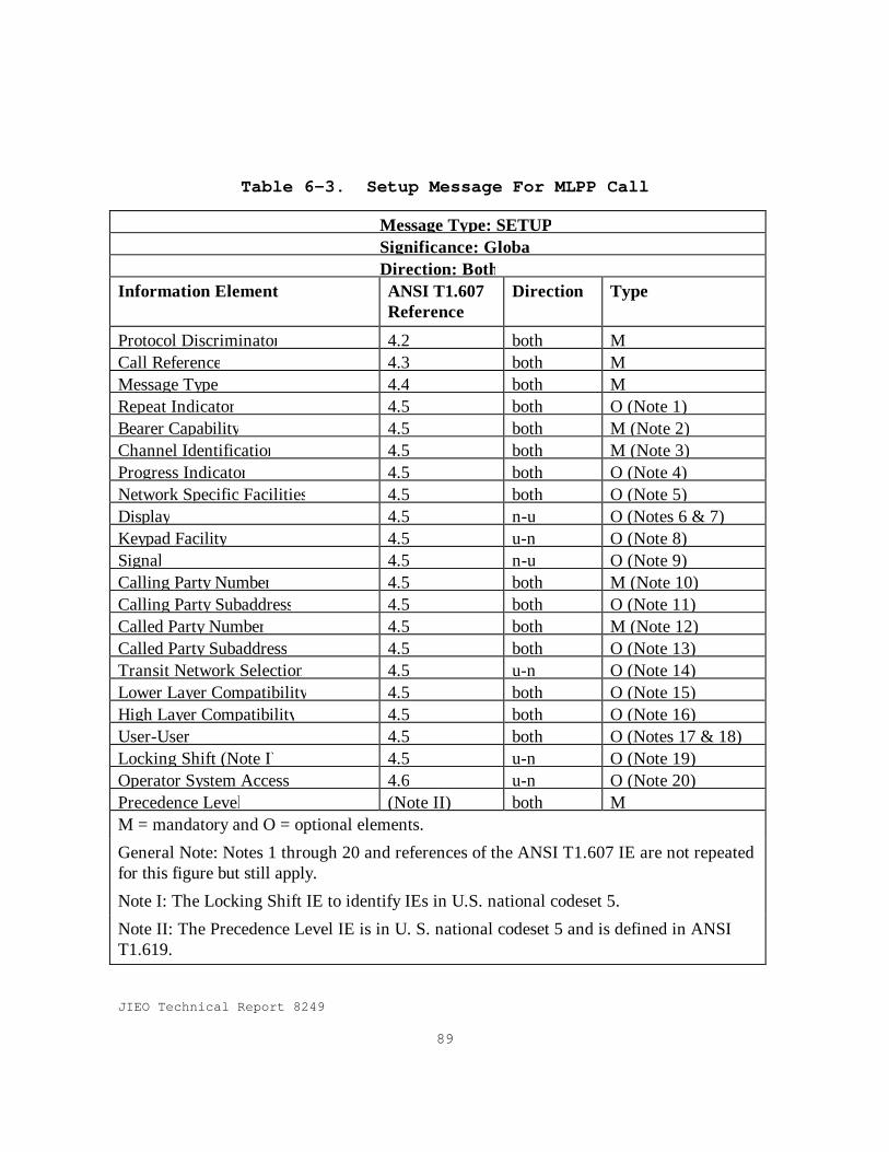
JIEO Technical Report 8249
89
Table 6-3. Setup Message For MLPP Call
Message Type: SETUPSignificance: GlobalDirection: Both
Information Element ANSI T1.607Reference
Direction Type
Protocol Discriminator 4.2 both MCall Reference 4.3 both MMessage Type 4.4 both MRepeat Indicator 4.5 both O (Note 1)Bearer Capability 4.5 both M (Note 2)Channel Identification 4.5 both M (Note 3)Progress Indicator 4.5 both O (Note 4)Network Specific Facilities 4.5 both O (Note 5)Display 4.5 n-u O (Notes 6 & 7)Keypad Facility 4.5 u-n O (Note 8)Signal 4.5 n-u O (Note 9)Calling Party Number 4.5 both M (Note 10)Calling Party Subaddress 4.5 both O (Note 11)Called Party Number 4.5 both M (Note 12)Called Party Subaddress 4.5 both O (Note 13)Transit Network Selection 4.5 u-n O (Note 14)Lower Layer Compatibility 4.5 both O (Note 15)High Layer Compatibility 4.5 both O (Note 16)User-User 4.5 both O (Notes 17 & 18)Locking Shift (Note I) 4.5 u-n O (Note 19)Operator System Access 4.6 u-n O (Note 20)Precedence Level (Note II) both MM = mandatory and O = optional elements.
General Note: Notes 1 through 20 and references of the ANSI T1.607 IE are not repeatedfor this figure but still apply.
Note I: The Locking Shift IE to identify IEs in U.S. national codeset 5.
Note II: The Precedence Level IE is in U. S. national codeset 5 and is defined in ANSIT1.619.
JIEO Technical Report 8249
90
6.6.6.2.3 General Message Format and InformationElements (IE) Coding. The guidelines specified in the ANSIT1.607 shall be followed in this specification.
a. Application of Codesets within the DSN . The DSN uniqueIEs, if any, shall employ the following order ofpreference in using the codesets:
(1) Codeset 0 - highest.
(2) Codeset 5.
(3) Codeset 6 - lowest.
b. Application of Information Elements (IEs) in the DSN .The DSN user-to-network signaling protocol shall maximizethe use of codeset "00" (ITU standardized coding) andcodeset "10" (national standard) IEs (when codeset "00"is not possible). Following are guidelines for thespecific use of such IEs in the DSN.
(1) Called Party Number Information Element (IE) . TheCalled Party Number IE, which identifies one called partyof a call, shall accommodate the DSN numbering plan. Thevariable length number digits parameter in theinformation element may carry the area code, switch code,and line number from the DSN numbering plan.
(2) Calling Party Number Information Element (IE). TheCalling Party Number IE, which identifies the origin of acall, shall accommodate the DSN WDNP as stated for theCalled Party Number IE.
(3) Keypad Facility Information Element (IE ). TheKeypad Facility IE, which conveys ASCII charactersentered by means of a terminal keypad (when employed),shall contain the digits entered by a DSN user.
(4) Channel Identification Information Element (IE) .The Channel Identification IE identifies a channel withinthe interface(s) controlled by the signaling procedures.The channel number/slot map parameter within itidentifies the B-channel controlled by a particularmessage. The following two methods of B-channel
JIEO Technical Report 8249
91
identification are available for use in the DSN: binarychannel number assigned to the channel and a slot mapthat identifies the time slots used by the channel. Theparameter shall be coded exclusively for one methoddepending upon the number/map parameter information. Bothprimary rate interfaces, 1.544 Mbps and 2.048 Mbps, shallbe supported in accordance with the slot map in ITU-TQ.931.
(5) Transit Network Selection Information Element (IE) .The Transit Network Selection IE identifies one requestedtransit network. It may be repeated in a message toselect a sequence of transit networks through which acall must pass. For example, the element may be employedin a SETUP message to specify one or a sequence oftransit networks (other than the user-assigned transitnetwork) through which a call must pass. In the case ofthe DSN user-to-network signaling, this IE shall be usedto specify the DSN or a network other than the DSN as atransit network. (DoD networks and foreign PTTs areexamples.)
(6) Cause Information Element (IE). The Cause IE shallbe in accordance with ANSI T1.619a.
(7) Signal Information Element (IE). The Signal IE,shall be in accordance with ANSI T1.619a. The signalshall be included in the DISCONNECT, PROGRESS, and SETUPmessages as appropriate for the MLPP feature.
(8) Notification Indicator Information Element (IE) .The Notification Indicator IE, which indicatesinformation pertaining to a call, shall contain thenotification description code of "0 0 0 0 1 0 0" (value4) for the MLPP feature to indicate to the calling user apossible call completion delay when an LFB query isinvoked in response to an MLPP call setup.
6.6.6.3 Supplementary Services.This paragraph provides DSN user-to-network signaling for
layer 3 protocols for ISDN supplementary services.
Supplementary services shall be as specified in ANSI T1.610,which is a pointer document to and aligned with ITU
JIEO Technical Report 8249
92
Recommendation Q.932 except that the Keypad Facility IE shallnot be used in the network-to-user direction. The genericprocedures described in this GSCR shall be used in the DSN forthe invocation and operation of supplementary services inassociation with existing calls or outside any existing calls.Application of these and layer 3 call control procedures toDSN features are contained in Section 21 of thisspecification.
The IS-UP messages, which may be used to develop proceduresfor DSN ISDN features, shall be as defined in Section 5.1 ofQ.932 (for Feature Key Management protocol) and Section 7.1 ofQ.932 (for Functional protocol), in addition to thosespecified in ANSI T1.607.
The information elements, which may be used to developprocedures for DSN features, shall be as defined in Section8.2 of Q.932, and specified in ANSI T1.607.
JIEO Technical Report 8249
93
Section 7
Transmission
7.1 GeneralThis section contains the generic transmission requirements
applicable to DSN MFS and EO switching systems. This sectionis based on LSSGR Section 7, TR-NWT-000507, and follows thesame format.
7.1.1 Requirements TerminologyLSSGR Section 7, Transmission, describes three types of
requirements: (1) Requirement, (2) Conditional Requirement,and (3) Objective. DSN switching systems shall meet all LSSGRrequirements. Conditional requirements should be met whenpossible.
7.2 Transmission PerformanceLSSGR Section 7, paragraph 7.2 and the following
subparagraphs discuss transmission performance in terms of aplan resulting in a loss-noise-echo grade of service rating.While this section does not contain requirements, the theoriesdiscussed do pertain to DSN.
7.3 Transmission Loss PlansLSSGR Section 7, Paragraph 7.3 and its subparagraphs discuss
three types of network loss plans: (1) Via Net Loss, (2) FixedLoss, and (3) Loss Plan for Evolving Digital Networks. SinceDSN is evolving to an all digital environment, therequirements for the Loss Plan for Evolving Digital Networksshall apply.
7.4 Loss Plan ImplementationDSN switching systems shall meet all the Loss Plan
Implementation requirements in LSSGR Section 7, paragraph 7.4and its subparagraphs. Digital signal processing results inthe modification of the bit stream transported on digitalfacilities. Since encrypted signals must not lose bit
JIEO Technical Report 8249
94
integrity, digital signal processing shall not be used forinserting loss within the DSN. In locations where the use ofthe Loss Plan for Evolving Digital Networks cannot beimplemented, the Fixed Loss Plan detailed in DCAC 370-175-13may be implemented by site specific contracts.
7.5 Switching System Interfaces and ConnectionsDSN switching systems shall meet all the switching system
interface, loop characteristics, and office cablingrequirements in LSSGR Section 7, paragraph 7.5, and itssubparagraphs.
7.6 Transmission Measurement TechniquesDSN switching systems shall be capable of using the
techniques for verifying compliance with transmissionrequirements described in LSSGR Section 7, paragraph 7.6 andits subparagraphs. DSN switching systems shall meet therequirements in paragraph 7.6 and its subparagraphs.
7.7 Performance Requirements
7.7.1 GeneralDSN switching systems shall meet the requirements in LSSGR
Section 7, paragraph 7.7 and all its subparagraphs unlessmodified by the GSCR.
7.7.2 Loss and VariabilityDSN switching systems shall meet the requirements for loss
performance, loss variability, and tracking error as specifiedin LSSGR Section 7, Paragraph 7.7.2 and its subparagraphs.
7.7.3 Attenuation DistortionDSN switching systems shall meet the requirements for
attenuation distortion as specified in LSSGR Section 7,Paragraph 7.7.3 and its subparagraphs.

JIEO Technical Report 8249
95
7.7.4 NoiseDSN switching systems shall meet the requirements for
C-Message Weighted Idle Noise, Signal-to-Distortion Ratio, andImpulse Noise as specified in LSSGR Section 7, Paragraph 7.7.4and its subparagraphs.
7.7.5 Input ImpedanceDSN switching systems shall meet the requirements for input
impedance as specified in LSSGR Section 7, Paragraph 7.7.5 andits subparagraphs. In addition to the Input Impedance atAnalog Interfaces in Table 7.7-7 of the LSSGR the impedancefor an analog interface at an RSU ( ≥ 2 dB loss) is shown inTable 7-1.
Table 7-1. Input Impedance (≥ 2 dB loss)
Analog Interface Reference Impedance FrequencyRange
Return Loss(Minimum)
LI or 4-Wire Trunk(RSU)
(≥ 2dB loss)
900 ohms
+2.1 microfarad
200-500Hz
500-3400Hz
14dB
20dB
7.7.6 Envelope Delay DistortionDSN switching systems shall meet the requirements for
envelope delay distortion as specified in LSSGR Section 7,Paragraph 7.7.6 and its subparagraphs.
7.7.7 LinearityDSN switching systems shall meet the requirements for
overload compression and intermodulation distortion asspecified in LSSGR Section 7, Paragraph 7.7.7 and itssubparagraphs.
JIEO Technical Report 8249
96
7.7.8 Single Frequency DistortionDSN switching systems shall meet the requirements for single
frequency distortion as specified in LSSGR Section 7,Paragraph 7.7.8.
7.7.9 Echo Path DelayDSN switching systems shall meet the requirements for Echo
Path Delay and Echo Path Delay Advisory for 0-dB ConnectionLoss as specified in LSSGR Section 7, Paragraph 7.7.9.
7.7.10 Talker and Listener Echo ControlEcho control in the DSN network shall meet the requirements
in DISA Circular DISAC 370-175-13.
7.7.11 Longitudinal BalanceDSN switching systems shall meet the requirements for
Longitudinal Balance as specified in LSSGR Section 7,Paragraph 7.7.11.
7.7.12 CrosstalkDSN switching systems shall meet the requirements for
crosstalk as specified in LSSGR Section 7, Paragraph 7.7.12and its subparagraphs.
7.7.13 Digital ImpairmentsDSN switching systems shall meet the requirements Digital
Loss, Bit Error Ratio, Slip Rate, Jitter, and Framing asspecified in LSSGR Section 7, Paragraph 7.7.13 and itssubparagraphs. In addition DSN switching systems shall meetthe Bit Error Ration objective of no worse than one error in109 pulses specified in paragraph 7.7.13.2.
7.7.14 Conference Bridging FacilitiesDSN switching systems shall meet the requirements for
Conference Bridging Facilities as specified in LSSGR Section7, Paragraph 7.7.14.

JIEO Technical Report 8249
97
Section 8
Automatic Message Accounting (AMA)
8.1 IntroductionThe AMA process in a switching system provides usage related
data to perform customer billing, studies on network usage,and message detail recording. AMA recording requirementsinclude:
1. Data Generation2. Bellcore AMA Format (BAF)3. AMA Data Retention4. AMA Data Output5. AMA Timing6. AMA Reliability and Quality7. Miscellaneous AMA Requirements
8.2 AMA RequirementsDSN switching systems shall meet all the requirements
specified in LSSGR Section 8. The following LSSGR AMAConditional Requirements are required for DSN switchingsystems.
8.2.1 Settable BAF FieldsThe settable fields in LSSGR Section, 8, paragraph 3.1.4,
Table 1, shall also include the Military Call Detail Recordfields shown in Table 8-1.
8.2.2 Minimum Retention TimeConditional requirements CR5-2 through CR5-11 are
requirements for DSN switching systems.
8.2.3 Removable Hardcopy RecordingIf switching systems employ nine-track tape for recording
AMA data the conditional requirements in LSSGR Section 8,paragraph 6.3.1 and its subparagraphs are DSN requirements.
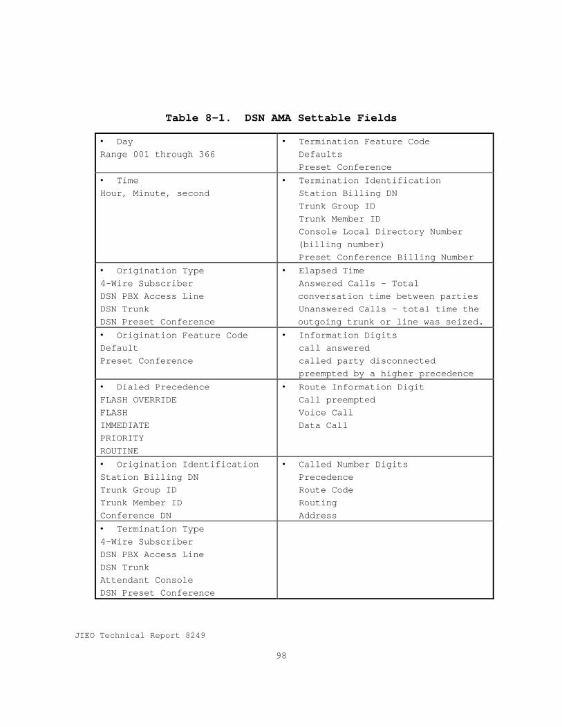
JIEO Technical Report 8249
98
Table 8-1. DSN AMA Settable Fields
• Day Range 001 through 366
• Termination Feature CodeDefaultsPreset Conference
• Time Hour, Minute, second
• Termination IdentificationStation Billing DNTrunk Group IDTrunk Member IDConsole Local Directory Number(billing number)Preset Conference Billing Number
• Origination Type 4-Wire Subscriber DSN PBX Access Line DSN Trunk DSN Preset Conference
• Elapsed TimeAnswered Calls - Totalconversation time between partiesUnanswered Calls - total time theoutgoing trunk or line was seized.
• Origination Feature Code Default Preset Conference
• Information Digitscall answeredcalled party disconnectedpreempted by a higher precedence
• Dialed Precedence FLASH OVERRIDE FLASH IMMEDIATE PRIORITY ROUTINE
• Route Information DigitCall preemptedVoice CallData Call
• Origination Identification Station Billing DN Trunk Group ID Trunk Member ID Conference DN
• Called Number DigitsPrecedenceRoute CodeRoutingAddress
• Termination Type 4-Wire Subscriber DSN PBX Access Line DSN Trunk Attendant Console DSN Preset Conference
JIEO Technical Report 8249
99
Section 9
Measurements and Administration
9.1 IntroductionThis section specifies DSN switching system requirements for
traffic measurements, service measurements, serviceevaluation, database management, and generic programalteration. All requirements and “desirable” features andcapabilities in Bellcore LSSGR Section 9, shall be included inDSN switching systems.
9.2 Traffic ManagementDSN switching systems shall meet all the traffic measurement
requirements specified in LSSGR Section 9, paragraphs 8.2 andits subparagraphs with the following modifications andadditions.
a. Paragraph 8.2.2.1 A - Usage data shall be co llected interms of actual “seconds of use”.
b. Paragraph 8.2.2.1 A - Usage scanning is not an acceptablealternative.
c. Paragraph 8.2.2.1 A - Usage data totals shall not beestimated by a sampling technique.
d. Paragraph 8.2.2.7 - The requirements for Se parations areoptional and will be included in site specific contractswhen required.
e. Paragraph 8.2.2.10 - Measurements related to centralizedautomated message accounting (CAMA) requirements areoptional and will be included in site specific contractswhen required.
9.2.2.1 DSN Unique MeasurementsThe following MLPP trunk group metering measurement data
shall be collected for each of the precedence levels aboveROUTINE (PRIORITY, IMMEDIATE, FLASH, and FLASH OVERRIDE).
a. Outgoing Peg Count, Idle Search. Counts the number ofcalls that attempt an actual, physical search to find anidle circuit on a trunk group or access line.

JIEO Technical Report 8249
100
b. Overflow, Idle Search. Counts the number of calls thatattempt an actual, physical search of a trunk group andfail to find an idle circuit.
c. Outgoing Peg Count, Preemptive Search . Counts the numberof calls that attempt an actual, physical preemptivesearch to find either an idle or preemptable circuit on atrunk group or access line.
d. Overflow, Preemptive Search. Counts the number of callsthat attempt an actual, physical preemptive-search of atrunk group and fail to find either an idle orpreemptable circuit.
e. Preemptions. Counts the number of calls completed on atrunk group or access line by the use of preemption.
f. Incoming Peg Count. Counts the number of incomingseizures by precedence level. The incoming peg countshall include scorings due to preemptions in the MLPPtrunk group metering package. This will ensure thevalidity of the following equation when applied to a MLPPtrunk group between originating and terminatingdestinations:
Outgoing Peg Count Idle Search
- Overflow Idle Search
+ Outgoing Peg Count Preemptive Search
- Overflow Preemptive Search
= Incoming Peg Count
g. All Trunks Busy (ATB), Office Totals . The switch shallprovide the following ATB registers at an office totallevel:
(1) A count of the number of call attempts from localline-to-local line receiving an ATB signal at theoffice.
JIEO Technical Report 8249
101
(2) A count of the number of local line-to-trunkoriginating DSN calls receiving an ATB signal at theoffice.
9.3 Service MeasurementsSwitching system service measurements provide a switching
system view of the quality of network service provided. Themain goal is to identify those measurements needed to derivethe overall rate of user-perceived call failures, callincompletions and inability to access the switching system.DSN switching systems shall meet all the requirements in LSSGRsection 9, paragraph 8.3 and its subparagraphs.
9.4 Service EvaluationSwitching system service evaluation requirements specified
in LSSGR section 9, paragraph 8.4 are optional for DSNswitching systems and may be specified in site specificcontracts.
9.5 Database ManagementDSN switching systems shall meet all the database management
requirements specified in LSSGR Section 9, paragraph 8.5 andits subparagraphs with the following modifications andadditions.
a. Paragraph 8.5.4 Access to the Database. In addition tothe remote centralized locations which shall have accessto switching system databases, DSN Regional ControlFacilities shall have remote access to the database.
b. Paragraph 8.5.4.1 Database Maintenance Access. A remotedatabase maintenance channel shall be provided for DSNRegional Control Facilities.
9.6 Generic Program AlterationAlterations to switch generic programs (software that is an
integral part of the switch and supplied by the switch vendor)shall be altered by the vendor in accordance with the BellcoreLSSGR, Section 9, paragraph 8.6 and its subparagraphs.

JIEO Technical Report 8249
103
Section 10
System Interfaces
10.1 Analog Interface.DSN switching systems shall provide the following analog
interfaces.
10.1.1 Trunk and Gateway Trunk CircuitsThe DSN switch shall provide analog trunk circuits that
interface to industry standard signaling and facilityarrangements as described in DSN System Interface Criteria,DCAC 370-175-13.
10.1.1.1 CompatibilityThe interface shall be fully compatible with existing ISTs
and gateway trunks and Section 6, Signaling.
10.1.1.2 DirectionalizationEach IST and gateway trunk shall be programmable to function
as a two-way, an incoming, or an outgoing trunk.
10.1.1.3 Electrical CharacteristicsThe interface shall be fully compatible with the electrical
characteristics specified in GSCR, Section 7, Transmission.
10.1.1.4 SignalingThe MFS shall support trunk signaling as described in
Section 6, Signaling.
10.1.1.5 European InterfacesThe following interfaces are optional for DSN EO and PBX
switching systems but may be specified on systems which areinstalled in the European theater. The interfaces are definedin DISA Circular 370-175-13.
a. 2280 Hz
b. Type II and V E&M
c. Dual Frequency Signal Unit
d. 2-wire IKZ

JIEO Technical Report 8249
104
e. 2-wire HKZ
f. 2-wire 50 Hz
g. 2-wire 25/50 Hz Ringdown
10.1.2 Operator, Directory Assistance, and Intercept Systems.The analog Operator System Trunk, Directory Assistance, and
Intercept Systems interfaces in the Bellcore LSSGR, Section10, shall also be provided by DSN switching systems.
10.1.3 Access Line InterfaceDSN switching systems shall provide 4-wire access lines and
2-wire station lines as described in DCAC 370 -175-13.
10.2 Digital Interfaces.The DSN switch shall provide digital interfaces that
interface to industry standard signaling and facilityarrangements as described in DCAC 370-175-13.
10.2.1 EncodingConversion from A law to mu=255 law encoding shall be
supplied for all nailed termination between PCM -30 and PCM-24facilities in accordance with ITU-T Recommendations G.711 andG.802.
10.2.2 Digital Line InterfaceThe MFS and EO shall be capable of providing direct digital
interface to user lines. Digital interfaces shall supportboth BRI and non-BRI services.
10.2.2.1 Non-Basic Rate Interface (BRI) LinesDSN switching systems shall support direct digital line
interface over 2-wire loops as follows:
a. Asynchronous. The MFS, TS, and EO shall support fullduplex asynchronous digital data transfer at data ratesof 2.4, 4.8, 9.6, 16, 19.2, and 28.8 kbps.

JIEO Technical Report 8249
105
b. Synchronous. The MFS, TS, and EO shall support fullduplex synchronous data transfer at data rates of 32, 56,or 64 kbps.
10.2.2.2 BRI LinesDSN switching systems shall be capable of supporting ISDN-
BRI interface as specified in DCAC 370-175-13.
10.2.3 Trunk and Access Line CombinationsThe digital interface shall be capable of accommodating both
trunks and access lines in any combination within a 1.544 MbpsPCM-24 or 2.048 Mbps PCM-30 group.
10.3 Support System Interface ProtocolOperating systems are use to provide centralized support for
maintenance and administration of switching systems. Theinterface between DSN switching systems and the Governmentoperation, administration, maintenance platform shall use theX.25 protocol in accordance with the Bellcore LSSGR, Section10, paragraph 10.3.
10.4 Switch Cross-Connection SystemsThe interconnection of distribution frames (DFs) and digital
cross-connect frames shall be in accordance with the BellcoreLSSGR, Section 10, paragraph 10.4. In addition digital cross-connect frames in the European theater must provide E-1 (2048Mbps)European interfaces.
10.5 Commercial Access LinesDSN switching systems may provide an interface to the local
commercial telephone exchange. This interface may be 4 -wireor 2-wire as specified by site specific contracts. Signaling,supervision, and electrical characteristics shall be inaccordance with host nation practices. European commercialinterfaces will normally be ITU-T defined PRI at 2.048 Mbps.The analog interfaces defined in DCAC 370-175-13 also apply ona site specific basis.

JIEO Technical Report 8249
106
10.6 Tactical InterfaceWhen required by the site specific contract, the switch
shall interface with tactical switches as specified in DCAC370-175-13.
10.7 DRSN InterfaceWhen required by the site specific contract, DSN-DRSN
interfaces are implemented using the following methods:
a. DSN to DRSN RED Switch. The DSN switch is connectedto the DRSN RED switch via a Secure Telephone Unit,model 3R (STU-III/R) terminal terminated on the DSNMFS or EO on a 2-wire station line.
b. DSN to DRSN BLACK Switch. The DSN switch is connectedto the DRSN BLACK switch via either an analog 4-wireE&M trunk or digital trunk.
10.8 North Atlantic Treaty Organization (NATO)Initial Voice Switched Network (IVSN) Interface
The DSN-NATO IVSN interface, when required by the sitespecific contract, shall be implemented as specified in DCAC370-175-13.
10.9 Release Link Trunks (RLTs)RLT circuits shall be provided for use with the centralized
attendant service (CAS) capability. The switching system andthe attendant subsystem shall be capable of generating andresponding to all signaling and supervision necessary forproper RLT operation. Other methods may be utilized tosupport all of the features of CAS. The common user trunksshall be used for access to and egress from the CAS for allswitches.
10.10 Synchronous Optical Network (SONET) InterfaceWith the rapid growth of optical fiber transmission
facilities, it is appropriate to describe the genericrequirements for a high capacity SONET digital switchinterface. When a SONET interface is specified in sitespecific contracts for DSN switching systems it shall meet the

JIEO Technical Report 8249
107
generic requirements specified in the Bellcore LSSGR, Section10, Technical Reference TR-TSY-000782, SONET Digital SwitchTrunk Interface Criteria. In the European theater opticalfiber interfaces supplied by commercial carriers meet ITU-TRecommendation G.707. General Aspects of Digital TransmissionSystem - Synchronous Digital Hierarchy Bit Rates, 3/93.Synchronous Digital Hierarchy (SDH) level one (SDH-1) and theOC-3 rate use in the United States are equivalent.
10.11 SynchronizationThe primary reference for DSN synchronization is the Global
Positioning System (GPS/CDS-10) or a primary source traceableto a Stratum-1 clock. Also, DSN switching systems shall becapable of generating an internal reference clock and becapable of synchronizing with the DSN or public switchednetwork connected via digital signal 1 (DS1) digitaltransmission facilities. In the European theater ITU-T E-1signal may be used for external synchronization. At selectedlocations, the switch shall be capable of serving as master ina master-slave relationship with other switching systems
10.11.1 Timing ModesDSN switching systems shall meet the timing mode
requirements specified in the Bellcore LSSGR, Section 10,GR-518-CORE, paragraph 18.1.
10.11.2 Internal Clock Requirements.DSN switching systems shall meet the internal clock
requirements specified in the Bellcore LSSGR, Section 10,GR-518-CORE, paragraph 18.2. In addition the followingrequirements shall also be met.
10.11.2.1 Fast (Acquisition) ModeAn operating condition of a slaved clock in which it is
locked to an external reference and is using time constantsthat are altered to quickly bring the local oscillator’sfrequency into approximate agreement with the synchronizationreference frequency.
JIEO Technical Report 8249
108
10.11.2.2 Normal (Tracking Mode)This is the normal operating condition of a slaved clock.
The clock is locked to an external synchronization referenceand is using its normal time constants.
10.11.2.3 Initial Clock ConfigurationRegardless of the timing configuration at system cut-over,
the installed switch shall include all equipment necessary topermit operation using an external timing reference.Provisions shall be made to connect directly to a localstation clock and indirectly, through DS1 or E-1 facilities,to a remote timing reference.
10.11.2.4 External Reference Source SwitchoverWhen configured for external synchronization, the DSN switch
shall be capable of maintaining synchronization in the eventexcessive slip rate is detected or the primary timingreference is lost. Automatic switchover to two alternatesources shall be provided in the following order:
a. To a designated alternate timing reference if available.b. To the DSN switch internal clock.
10.11.3 Synchronization Performance CriteriaDSN switching systems shall meet the synchronization
requirements specified in the Bellcore LSSGR, Section 10,GR-518-CORE, paragraph 18.3. In addition the followingrequirements shall also be met.
10.11.3.1 Synchronization During Abnormal OperatingConditionsThe DSN switch shall be capable of assuring satisfactory
performance of the system clock and synchronization equipmentduring the following abnormal operating conditions describedin the LSSGR:
a. DS1 loss of signal.b. DS1 out of frame conditions.c. Frequency offset.d. Phase step.e. Excessive jitter.f. Fast start time-out.
JIEO Technical Report 8249
109
g. Hardware faults.h. End of range indications.
10.11.3.2 Satellite TransmissionSynchronization will be supported by data buffers that are
either built into the transmission equipment or are separatestand-alone units when terminating satellite derivedtransmission. Stand-alone buffers will accommodate ± 10 mspath delay variation of satellite transmission at a data rateof 1.544 Mbps.
10.12 Integrated Digital Loop Carrier (IDLC)DSN switching systems shall interface with IDLC equipment in
accordance with Bellcore GR-303-Core.

JIEO Technical Report 8249
111
Section 11
Service Standards
This section describes the performance requirements for callprocessing in a DSN switching system. The service standardsare expressed in terms of blocking and delay requirements thatapply to the entire switching system.
11.1 GeneralDSN switching systems shall meet the service standards in
the Bellcore LSSGR, Section 11, as modified by the followingparagraphs. The performance requirements in this section areoverall system requirements. They apply to systems withdistributed processing and modular architectures, timedivision and space division switches and include the effectsof any pair-gain techniques.
11.2 Busy Hour Criteria
11.2.1 Traffic LoadDSN switching systems shall use the Average Busy Season Busy
Hour (ABSBH) defined in the LSSGR, Section 11, paragraph11.2.1.2, in determining the load on DSN switches. Data usedto determine the load will be provided with site specificcontracts.
11.2.2 DefinitionsThe definitions for the types of criteria, network services,
dial tone delay, service circuits, and remote switches andmodules are in the LSSGR, Section 11, paragraph 11.2.2.
11.2.3 Busy Hour Service StandardsDSN switching systems shall meet the busy hour service
criteria in the LSSGR, Section 11, paragraph 11.2.3 and Table11-A. In addition the following service standards shall bemet.
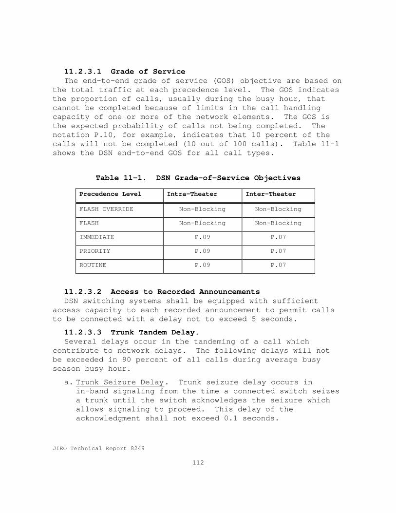
JIEO Technical Report 8249
112
11.2.3.1 Grade of ServiceThe end-to-end grade of service (GOS) objective are based on
the total traffic at each precedence level. The GOS indicatesthe proportion of calls, usually during the busy hour, thatcannot be completed because of limits in the call handlingcapacity of one or more of the network elements. The GOS isthe expected probability of calls not being completed. Thenotation P.10, for example, indicates that 10 percent of thecalls will not be completed (10 out of 100 calls). Table 11-1shows the DSN end-to-end GOS for all call types.
Table 11-1. DSN Grade-of-Service Objectives
Precedence Level Intra-Theater Inter-Theater
FLASH OVERRIDE Non-Blocking Non-Blocking
FLASH Non-Blocking Non-Blocking
IMMEDIATE P.09 P.07
PRIORITY P.09 P.07
ROUTINE P.09 P.07
11.2.3.2 Access to Recorded AnnouncementsDSN switching systems shall be equipped with sufficient
access capacity to each recorded announcement to permit callsto be connected with a delay not to exceed 5 seconds.
11.2.3.3 Trunk Tandem Delay.Several delays occur in the tandeming of a call which
contribute to network delays. The following delays will notbe exceeded in 90 percent of all calls during average busyseason busy hour.
a. Trunk Seizure Delay. Trunk seizure delay occurs inin-band signaling from the time a connected switch seizesa trunk until the switch acknowledges the seizure whichallows signaling to proceed. This delay of theacknowledgment shall not exceed 0.1 seconds.
JIEO Technical Report 8249
113
b. Switch Processing Delay. Upon receipt of signalinginformation the switch selects an idle path in thecorrect route and sends a trunk seizure to the distantswitch. The time from the receipt of signaling until thetrunk seizure shall be less than 0.1 seconds.
c. Signaling Delay. Once the distant switch acknowledgesthe trunk seizure, the switch shall begin signalingwithin 0.1 seconds.
11.3 Non-Traffic Sensitive CriteriaDSN switching systems shall meet the criteria for post
dialing delay, answer supervision delay, cutoff calls, andineffective attempts as defined in the LSSGR, Section 11,paragraph 11.3.


JIEO Technical Report 8249
115
Section 12
Reliability
12.1 IntroductionThis section contains the generic hardware reliability
modeling requirements and field reliability performancerequirements for DSN switching systems. The reliabilityrequirements are based on the Bellcore LSSGR, Section 12. Allrequirements and objectives of LSSGR Section 12 shall be metby DSN switching systems.
12.2 Application of Reliability CriteriaThe reference switch for the reliability requirements is a
typical EO switch containing ISDN BRI and PRI user interfacesand related subsystems as well as non-ISDN lines and relatedsubsystems. Tandem switches, and combined EO/tandem switchesare also covered by this section.
12.3 Hardware Reliability Modeling MethodsThe DSN switching system supplier shall provide the hardware
reliability predictions in the Bellcore LSSGR, Section 12,paragraph 3 and its subparagraphs, using the Bellcore modelingmethods.
12.4 Hardware Reliability ParametersHardware reliability parameters are defined in the Bellcore
LSSGR, Section 12, paragraph 4 and its subparagraphs.
12.5 Hardware Reliability RequirementsDSN switching systems shall meet the hardware reliability
requirements in the Bellcore LSSGR, Section 12, paragraph 5and its subparagraphs.
12.6 Application of Field Performance RequirementsField performance requirements apply to switch service
interruptions for all causes. Attainment of field reliabilityrequirements is not solely the responsibility of the switch

JIEO Technical Report 8249
116
supplier, it is a partnership between the service provider(MILDEP/DISA) and the switch supplier. DSN switching systemsshall meet the requirement in the Bellcore LSSGR, Section 12,paragraph 6 and its subparagraphs.
12.7 Outage Reporting and AnalysisOutage reporting and analysis shall be as described in the
Bellcore LSSGR, Section 12, paragraph 7 and its subparagraphswith the exception that reports shall be submitted toGovernment agencies/offices as specified in site specificcontracts and DISN AO&M procedures.
12.8 Definitions of Switch DegradationThe definitions of switch degradation applicable to DSN
switching systems are found in the Bellcore LSSGR, Section 12,paragraph 8 and its subparagraphs.
12.9 System Level Measures and Requirements.DSN switching systems shall meet the system level measures
and objectives in the Bellcore LSSGR, Section 12, paragraphs 9and 10 and their subparagraphs. The Bellcore objectives arerequirements for DSN switching systems.
12.10 Individual Termination RequirementsDSN switching systems shall meet the system level measures
and objectives in the Bellcore LSSGR, Section 12, paragraphs11 and its subparagraphs. The Bellcore objectives arerequirements for DSN switching systems.
12.11 Other Reliability CriteriaDSN switching systems shall meet reliability criteria for
outage recovery, cutoff calls, ineffective machine attempts,and quality switching system generic requirements inaccordance with the Bellcore LSSGR, Section 12, paragraphs 2and its subparagraphs.
JIEO Technical Report 8249
117
Section 13
Power
13.1 IntroductionDSN switching system power requirements are based on the
requirements in the Bellcore LSSGR, Section 13. The table ofcontents of Section 13 of the LSSGR is shown in the followingparagraph for readers not familiar with the LSSGR.
13.2 LSSGR ContentsI. General Information
A. Standby AC Plant
B. DC Power System
C. Battery Technologies
II. General Requirements
III. Functional Requirements
A. AC Power System
1. Commercial AC Service
a) Overvoltage Protection
b) AC Grounding Requirements
2. Stand-by AC Plants
3. AC Powered Equipment
a) General
b) No-Break Power System Requirements
c) Protected Power System Requirements
B. DC Power Systems
1. Power Equipment - AC Input Requirements
2. DC Power Plant Capacity
3. Output Voltage Range
JIEO Technical Report 8249
118
4. Telephone Influence Factor
5. Electrical Noise
6. DC Plant Start-Up Characteristics
7. DC Power System Grounding Requirements andDefinition
8. Grounding Interface
9. Batteries and Accessories
10. DC Distribution
11. Power Feeders
12. Current Drains
C. Power Plant Alarms
1. General
2. Alarm Categories
13.3 RequirementsDSN switching systems shall use the power provided by local
power companies, in the North America it shall meet the powerrequirements in the Bellcore LSSGR, Section 13. DSN switchingsystems located in the European theater may operate from thecommercial or primary AC power source of 50 ±3 Hz and 60 ±3 Hzsingle phase, 220 volt + 10 percent/20 percent withsuperimposed voltage spikes up to 220 volts peak and up to 100milliseconds in duration or a three phase power source of 386volts and up to 100 milliseconds in duration.
13.3.1 Battery Reserve TimeBattery reserve time is the amount of time a battery plant
can supply dc power within the circuit voltage limits of theload equipment at the busy-hour current drain. The amount ofbattery backup is dependent upon the availability of othertypes of alternate power sources. DSN switching systems thathave battery backup only shall have a reserve time of 8 hours.Sites with alternate power sources shall meet the recommendedreserve times in the LSSGR, Section 13, paragraph 2.3.3.

JIEO Technical Report 8249
119
Section 14
Network Equipment-Building System (NEBS)Requirements: Physical Protection
14.1 IntroductionThe NEBS is a set of requirements for physical and
environmental requirements for switching nodes and othertelephone facilities, buildings, and equipment used in thesefacilities. Section 14 of the Bellcore LSSGR contains thephysical requirements for telephone facilities and equipment.Because many DSN switching systems are located in Governmentowned buildings or in foreign countries, many of therequirements may not be applicable to DSN switching systems.However, a convincing argument could be made for the use ofthese requirements in DSN and they should be used asguidelines in preparing Government Furnished Facilities forDSN switching systems.
14.2 Structure of LSSGR Section 14Section 1, Introduction
Section 2, Spatial Requirements - Provides requirements forequipment and cabling systems to be compatible with switchingnode vertical and horizontal space allocations and floorloading limits. Part of this overall scheme is the cablepathways plan that coordinates the overhead cable distributionby allocating the system and via cable to different levels,both parallel and transverse to equipment frame line-ups.
Section 3, Provides requirements for the physical design ofcabinets and framework to help simplify planning andinstallation, ensure adequate physical strength, and provideuniformity between suppliers of telecommunications andcomputer equipment.
Section 4, Environmental Criteria - Provides requirementsfor equipment to help ensure their compatibility with thephysical environment provided by network facilities. Thisenvironment includes physical stresses from temperature,
JIEO Technical Report 8249
120
humidity, fire, earthquake and airborne contaminants, as wellas the acoustic noise and illumination characteristics ofthese facilities. The requirements should apply to allswitching node equipment systems.
Section 5, Environmental Test Methods - Presents testmethods that should be used to test equipment for conformanceto the environmental requirements in Section 4.

JIEO Technical Report 8249
121
Section 15
Electromagnetic Compatibility andElectrical Safety
15.1 IntroductionThis section specifies the electromagnetic compatibility and
electrical safety criteria for DSN switching systems. Therequirements are the minimum which DSN switching systems shallmeet. Individual site specific contract may require morestringent military or local government standards.
15.2 RequirementsDSN switching systems shall meet the electromagnetic
compatibility and electrical safety requirements in accordancewith the Bellcore LSSGR, Section 15. The requirementsinclude:
a. System-Level Electrostatic Dischargeb. Electromagnetic Interferencec. Lighting and AC Power Faultd. Steady-State Power Inductione. DC Potential Differencef. Electrical Safety Criteriag. Corrosionh. Bonding and Grounding


JIEO Technical Report 8249
123
Section 16
Network Traffic Management
16.1 IntroductionThis section contains the generic requirements for DSN
switching systems traffic measurements and controls that DSNpersonnel use to manage the DSN.
16.2 Scope of Network Traffic Management (NTM)Requirements
The scope of DSN NTM requirements is described in theBellcore LSSGR, Section 16, paragraph 2 and all itssubparagraphs except as modified by the following paragraphs.
16.2.1 Integrated NTM StrategyThe DISN is evolving into a network comprised of
interrelated classes of subnetworks (DSN, DRSN, NIPRNET, andSIPRNET), with each class using a specific architectural plan.However this specification addresses only the DSN portion ofthe DISN, therefore, the Public Packet Switched Network(PPSN), which is addressed in the LSSGR does not apply in thisspecification. Alternate Billing Service (ABS) and SwitchedMulti-megabit Data Services (SMDS)are not currently supportedby DSN, however they are considered as optional capabilitiesthat may be required in site specific contracts.
16.2.2 NTM Capabilities Guidelines.DSN switching systems shall meet the NTM requirements
defined in the LSSGR, Section 16, with the exception ofparagraph 2.7 which is not applicable to DSN switchingsystems.
16.3 Common Data RequirementsDSN switching systems shall meet the generic requirements,
conditional requirements and optional requirements for commondata in the LSSGR, Section 16, paragraph 3 and itssubparagraphs.
JIEO Technical Report 8249
124
16.4 NTM Surveillance DataSurveillance data is a basic set of measurements needed to
manage and control circuit switched networks. This sectionprovides basic data requirements for DSN switching systems.
16.4.1. Circuit Switch MeasurementsNetwork traffic managers need a basic set of measurements to
manage and control the circuit switched network. This sectionprovides the basic data requirement for the circuit switchednetwork.
16.4.1.1 Basic SwitchAll basic switch surveillance measurement requirements,
conditional requirements, and options in the LSSGR Section 16,paragraph 4.1.1 shall be met by DSN switching systems.
16.4.1.2 Line ServicingAll line servicing surveillance measurement requirements,
conditional requirements, and options in the LSSGR Section 16,paragraph 4.1.2 shall be met by DSN switching systems.
16.4.1.3 Trunk GroupsAll trunk group surveillance measurement requirements,
conditional requirements, and options in the LSSGR Section 16,paragraph 4.1.3 shall be met by DSN switching systems. Inter-LATA carrier conditional requirements, (CR)4-9, for accessattempts, overflows, and average trunk usage shall be appliedto FTS2000, IVSN, tactical, and DRSN trunk groups.
16.4.2 Switch ServicesAll switched service traffic measurement requirements,
conditional requirements, and options in the LSSGR Section 16,paragraph 4.2 shall be met by DSN switching systems. Inter-LATA carrier conditional requirements, (ConditionalRequirements 4-24 and 4-25), for IC destined calls and ICdestined calls - no circuit, shall be applied to FTS2000,IVSN, tactical, and DRSN trunk groups.
JIEO Technical Report 8249
125
16.4.3 Common Channel Signaling NetworkAll CCS network performance, service processing, and link
requirements and conditional requirements in the LSSGR Section16, paragraph 4.3 shall be met by DSN switching systems.
16.4.4 Number ServicesNumber services provide inward call management features and
require that specific number (e.g., 800) be dialed by thecustomer. These numbers are recognized by the serving switchand are provided with special call treatment. All numberservice NTM requirements, conditional requirements and optionsin the LSSGR Section 16, paragraph 4.4 shall be met by DSNswitching systems.
16.4.5 ISDNAll ISDN NTM requirements, conditional requirements and
options in the LSSGR Section 16, paragraph 4.5 shall be met byDSN switching systems.
16.4.6 Public Packet Switched Network (PPSN)PPSN NTM requirements in the LSSGR, Section 16, paragraph
4.6 are optional and when required will be specified in sitespecific contracts.
16.4.7 Alternate Billing Service (ABS)ABS NTM requirements in the LSSGR, Section 16, paragraph 4.7
are optional and when required will be specified in sitespecific contracts.
16.4.8 Switched Multi-Megabit Data Service (SMDS)SMDS NTM requirements in the LSSGR, Section 16, paragraph
4.8 are optional and when required will be specified in sitespecific contracts.
16.4.9 Switched Fractional DS1 Service (SWF-DS1)All SWF-DS1 NTM requirements, conditional requirements and
options in the LSSGR Section 16, paragraph 4.9 shall be met byDSN switching systems.

JIEO Technical Report 8249
126
16.5 NTM Automatic ControlsAn automatic control is an NTM control that is dynamically
triggered in response to a shortage in call processing or calltransport resources. Automatic controls are triggered when apreviously specified threshold is exceeded.
16.5.1 Description of NTM Automatic ControlsNTM controls are triggered by certain events and
automatically become active without intervention from thenetwork traffic manager or an NTM operating system. In theLSSGR two types of automatic controls are identified. Whenall information related to the automatic control isadministered and sent from an initiating network element tothe controlling network element, it is identified as a Type Acontrol. When the control is administered in the controllingnetwork element and is triggered by either a condition withinthe controlling network element or upon receipt of an alertingmessage from another network element, it is a Type B control.
16.5.2 User PerspectiveAlthough automatic control function without human
interaction, manual administration is sometimes necessary tooverride and/or adjust the response of automatic controls.This administration is performed by network traffic managers.NTM automatic controls shall be able to be monitored andimplemented by government network management facilities.
16.5.3 Circuit Switch Requirements16.5.3.1 Automatic Congestion Controls (ACC)DSN switching systems shall meet the ACC requirements and
options in the LSSGR, Section 16, paragraph 5.3.1 and itssubparagraphs. All ACC controls shall be able to beadministered and controlled from both a local terminal and aremote government NTM OS.
16.5.3.2 Automatic Call Gap (ACG)DSN switching systems shall meet the ACG requirements and
options in the LSSGR, Section 16, paragraph 5.3.2 and itssubparagraphs. All ACG controls shall be able to be

JIEO Technical Report 8249
127
administered and controlled from both a local terminal and aremote government NTM OS. FLASH and FLASH OVERRIDE callsshall not be subject to this control.
16.5.3.3 Trunk Reservation (TR)DSN switching systems shall meet the TR requirements and
options in the LSSGR, Section 16, paragraph 5.3.3 and itssubparagraphs. All TR controls shall be able to beadministered and controlled from both a local terminal and aremote government NTM OS.
16.5.3.4 Selective Incoming Load Control (SILC)DSN switching systems shall meet the SILC requirements and
options in the LSSGR, Section 16, paragraph 5.3.4 and itssubparagraphs. SILCs shall apply to incoming traffic from theFTS200, ISVN, DRSN, tactical, and commercial networks. AllSILCs shall be able to be administered and controlled fromboth a local terminal and a remote government NTM OS.
16.5.3.5 Media Stimulated Mass Calling (MSMC)Although the DSN is not subject to overloads stimulated by
MSMC events, sudden, unforeseen events can create the sameeffects in the DSN. Therefore, DSN switching systems shallmeet the MSMC requirements and options in the LSSGR, Section16, paragraph 5.3.5 and its subparagraphs. All MSMC controlsshall be able to be administered and controlled from both alocal terminal and a remote government NTM OS.
16.5.3.6 Dynamic Overload Control (DOC)With the advent SS7 and the ACC control, DOC is no longer
necessary as a required switch feature. Since DOC is used inconjunction with CCS in DSN, the DOC requirements in theLSSGR, Section 16, paragraph 5.3.6 and its subparagraphs areconsidered optional. If DOC is required in site specificcontracts, the LSSGR DOC requirements shall be met.
16.5.3.7 Automatic Operation with Hard To Reach (HTR) CodesThis capability applies to CCS6 and is not presently
supported by SS7, and therefore does not apply to DSNswitching.

JIEO Technical Report 8249
128
16.5.4 Common Channel Signaling NetworkDSN switching systems shall meet the CCS network controls
specified in the LSSGR, Section 16, paragraph 5.4.
16.5.5 Number Services.Number services network control requirements, conditional
requirements and options in the LSSGR Section 16, paragraph5.5 are optional and will be specified in site specificcontracts when required.
16.5.6 ISDNDSN switching systems shall meet the network control
requirements specified in the LSSGR, Section 16, paragraph5.6.
16.5.7 PPSNThe PPSN control requirements in the LSSGR, Section 16,
paragraph 5.7 are optional and when required will be specifiedin site specific contracts.
16.5.8 ABSABS network control requirements in the LSSGR Section 16,
paragraph 5.8 are optional and will be specified in sitespecific contracts when required.
16.5.9 SMDSSMDS network control requirements in the LSSGR Section 16,
paragraph 5.9 are optional and will be specified in sitespecific contracts when required.
16.5.10 Switched Fractional DS1 ServiceDSN switching systems shall meet the control requirements
specified in the LSSGR, Section 16, paragraph 5.10.
JIEO Technical Report 8249
129
16.6 NTM Manual ControlsA manual control is an NTM control implemented by the
network traffic managers, typically through the NTM operatingsystem.
16.6.1 Description of NTM Manual ControlsThere are three NTM control features, code controls, trunk
group controls, and code classification.
16.6.2 User PerspectiveNetwork traffic managers implement manual controls and
perform administration of HTR and non-reroutable codes. TheNTM OS provides network traffic managers with the capabilityto monitor and control the network in real time.
16.6.3 Circuit Switch Requirements.16.6.3.1 Code ControlsDSN switching systems shall meet the NTM code controls
specified in the LSSGR, Section 16, paragraph 6.3.1 and itssubparagraphs. Code control requirement 6-1 apply to all DSNswitching systems. The LSSGR IC carrier requirements(paragraph 6.3.1.2B) apply to the FTS2000, IVSN, DRSN, andtactical networks. The LSSGR international requirements(paragraph 6.3.1.2C) are considered optional and will bespecified in site specific contracts.
16.6.3.2 Trunk Group ControlsDSN switching systems shall meet the required, conditional
and optional NTM trunk group controls specified in the LSSGR,Section 16, paragraph 6.3.2 and its subparagraphs. FLASH andFLASH OVERRIDE calls shall not be subject to CANT and CANFcontrols.
16.6.3.3 Code ClassificationDSN switching systems shall meet the required, conditional
and optional NTM code classification controls specified in theLSSGR, Section 16, paragraph 6.3.3 and its subparagraphs.
JIEO Technical Report 8249
130
16.6.4 CCSDSN switching systems shall meet the CCS NTM controls in the
LSSGR, Section 16, paragraph 6.4.
16.6.5 Number Services.Number services network control requirements, conditional
requirements and options in the LSSGR Section 16, paragraph6.5 are optional and will be specified in site specificcontracts when required.
16.6.6 ISDNDSN switching systems shall meet the network control
requirements specified in the LSSGR, Section 16, paragraph6.6.
16.6.7 PPSNThe PPSN control requirements in the LSSGR, Section 16,
paragraph 6.7 are optional and when required will be specifiedin site specific contracts.
16.6.8 ABSABS network control requirements in the LSSGR Section 16,
paragraph 6.8 are optional and will be specified in sitespecific contracts when required.
16.6.9 SMDSSMDS network control requirements in the LSSGR Section 16,
paragraph 6.9 are optional and will be specified in sitespecific contracts when required.
16.6.10 Switched Fractional DS1 ServiceDSN switching systems shall meet the control requirements
specified in the LSSGR, Section 16, paragraph 6.10.
16.7 NTM OS/NE InterfacesDSN switching systems shall meet the embedded NTM OS
interface specifications in the LSSGR, Section 16, paragraph

JIEO Technical Report 8249
131
7.2.1. In addition DSN switching systems shall meet therequirements for abnormal conditions specified in the LSSGR,Section 16, paragraph 7.3.


JIEO Technical Report 8249
133
Section 17
Traffic Capacity and Environment
17.1 IntroductionSection 17 of the Bellcore LSSGR describes the capacity
objectives and traffic demand information for new switchingsystems. The LSSGR Section 17 table of contents is shown inthe following paragraph for readers that are not familiar withthe Bellcore LSSGR.
17.2 LSSGR ContentsI. Traffic Capacity and Environment
A. Introduction
B. Major Capacity Limits
1. Termination Capacity: Lines and Trunks
2. Call Capacity
3. Traffic Usage Capacity
C. Other Capacity Limits
D. Subsystem Capacity Considerations
1. Interface Subsystem Call Capacity
2. Interface Subsystem Concentration Ratios
E. Call Capacity Estimation
1. Definition of Call Capacity
2. Precutover Call Capacity Estimation forProcessors
a) Limiting Call Processing Occupancy
b) Average Real Time Per Call
c) Vendor Real-Time InformationRequirements
d) Call Mix Data for Engineering
JIEO Technical Report 8249
134
3. Processor Call Capacity Benchmarks
4. Postcutover Call Capacity Estimation forProcessors
5. System Capacity
a) Processor Capacity Comparisons
b) Processor vs. Network Capacity
c) Processor vs. Line Capacity
17.3 Traffic Capacity RequirementsDSN switching systems suppliers shall use the procedures in
the Bellcore LSSGR, Section 17 for determining the switchtraffic capacity and environment requirements.
JIEO Technical Report 8249
135
Section 18
Network Element and Network SystemSecurity
18.1 IntroductionThis section contains generic security requirements for DSN
switching systems. Security requirements are based on theBellcore LSSGR, Section 18, they are:
• Security feature requirements• Development life cycle requirements• Risk analysis for Associated Support Entities (e.g., and
Element Manager) that may perform operations relatedfunctions for network resources and or may assist in thehandling of a call.
Bellcore states the requirements in terms of NetworkElements (NEs) and Network Systems (NSs). Typical examples ofNEs are switching and transmission elements and Adjuncts andIntelligent Peripherals are examples of NSs. Therefore, therequirements apply to DSN switching systems.
The term “Government” shall be substituted for the phrase“BCC” in the Bellcore LSSGR.
The term “shall” shall be substituted for the phrase“should” in objective requirements which are designated as DSNrequirements.
18.2 Rationale for NE/NS Security MeasuresWith the advancements in digital technology and software
systems, processor-controlled NEs/NSs are proliferating in thenetwork. These NEs/NSs contain databases and different typesof software that are accessed and managed by users viadifferent interfaces. There are may different types of directand indirect interfaces to NEs/NSs, and the NEs/NSs areinterconnected within the network. These interfaces andconnectivity accentuate the security risks of unauthorized
JIEO Technical Report 8249
136
access to the NE/NS environment and its software anddatabases.
18.3 Security Feature Requirements
18.3.1 OverviewSection 18, paragraph 3.1 of the Bellcore LSSGR contains a
definition of the categories of NE/NS security features.
• Identification• Authentication• System access control• Resource access control• Security log (audit)• Data and system integrity• Security Administration
18.3.2 IdentificationDSN switching systems shall meet the identification
requirements and conditional requirements in the BellcoreLSSGR, Section 18, paragraph 3.2.
18.3.3 AuthenticationDSN switching systems shall meet the authentication
requirements, conditional requirements, and objectives in theBellcore LSSGR, Section 18, paragraph 3.3. Conditionalrequirement (CR)3-27, paragraph 2 is modified as follows.
“2. The user is notified upon password expiration, butallowed a specified additional number of subsequent loginsbefore requiring a new password. The default for the numberof subsequent logins shall not be greater than three. Theexpired password shall remain in effect for the number ofsubsequent logins until the new password is entered andvalidated. If a new password has not been entered withinthe authorized number of subsequent logins, new logins shallnot be allowed.”

JIEO Technical Report 8249
137
18.3.4 System Access ControlDSN switching systems shall meet the system access control
requirements, conditional requirements, and objectives in theBellcore LSSGR, Section 18, paragraph 3.4.
18.3.5 Resource Access ControlDSN switching systems shall meet the resource access control
requirements, conditional requirements, and objectives in theBellcore LSSGR, Section 18, paragraph 3.5.
18.3.6 Security Log (Audit)DSN switching systems shall meet the security log
requirements, conditional requirements, and objectives in theBellcore LSSGR, Section 18, paragraph 3.6 and itssubparagraphs.
18.3.7 Data and System IntegrityDSN switching systems shall meet the data and system
integrity requirements, conditional requirements, andobjectives in the Bellcore LSSGR, Section 18, paragraph 3.7and its subparagraphs.
18.3.8 Security AdministrationDSN switching systems shall meet the security administration
requirements, conditional requirements, and objectives in theBellcore LSSGR, Section 18, paragraph 3.8.
18.4 Development Life Cycle RequirementsSection 18, paragraph 4 of the Bellcore LSSGR contains
security requirements that a vendor should follow in thedevelopment life cycle of an NE/NS. While these requirementsare not features of a switching system the requirements shouldbe part of the contract if a vendor is developing switchingsoftware for the Government. The development life cyclerequirements cover requirements analysis, system design,detailed system design, implementation, developmentalenvironment, system test, packaging and delivery,documentation, and vendor support.


JIEO Technical Report 8249
139
Section 19
Documentation
19.1 GeneralDocumentation is an integral part of a switching system.
Switching system documentation shall be accurate and availablewhen needed. The Bellcore LSSGR, Section 19 specifies thedocumentation that the supplier shall provide with switchingsystems. Many of the requirements in Section 19 of the LSSGRare for work that the supplier must perform and thereforeshould be part of the Statement of Work, in site specificcontracts. The following documentation shall be supplied withDSN switching systems. LSSGR requirements not specified inthe following paragraphs may be included as part of theStatement of Work in site specific contracts.
19.2 Supplier Documentation and Translation GuideSupplier documentation that shall be provided as an integral
part of the DSN switching systems is described in the BellcoreSupplier Documentation for Network Elements, TR-TSY-000454,Issue 1, July 1988. Translation requirements and conditionalrequirements in the Translations Guide Generic Requirementsfor Network Elements, TR-TSY-000454, Issue 1, July 1988,Supplement 1, January 1994, shall also be provided as part ofDSN switching systems.
19.3 Supplier Support Generic RequirementsBellcore Technical Reference Supplier Support Generic
Requirements,TR-NWT-000840, Issue 1, December 1991 containsthe generic requirements for the support that suppliers areexpected to provide with their products, features, andservices. These requirements are for work to be performed bythe suppler and should be included as part of the SOW in sitespecific contracts.

JIEO Technical Report 8249
140
19.4 Documentation StandardsDocumentation provided with DSN switching systems shall meet
the documentation standards specified in the LSSGR, Section19, paragraph 19.3 and its subparagraphs.

JIEO Technical Report 8249
141
Section 20
Tandem Switching
20.1 IntroductionThis section contains the tandem switching requirements for
DSN MFSs and TSs. It is based on the Bellcore, LSSGR, Section20. The requirements in this section apply to systems usingexisting analog or digital technology. LSSGR Features andcapabilities which require modification for use in the DSN aredescribed as are Military Unique Features. Specifications forinterconnection to tactical networks, IVSN, and internationalcarriers are covered in DISA Circular 370-175-13.
20.2 Network PlanTandem switching systems provide a means of routing traffic
in an orderly manner and makes economic use of trunks andswitching equipment, where otherwise, many small separatetrunk groups would be necessary. The switch performs trunk-to-trunk switching for the purpose of concentrating trafficfor the centralization of services.
20.3 System ArchitectureThe switching system architecture is largely a function of
technology. DSN switching systems are digital and interfacewith both digital and analog access lines and trunks. The DSNarchitecture is described in Section 1 of this GSCR.
20.4 Tandem Switching Features and FunctionsDSN switching systems requiring tandem switching features
and functions shall provide the features and functions shownin Table 20-1 and defined in the Bellcore LSSGR, Section 20,paragraph 4.1. LSSGR features not shown in Table 20-1 areoptional and may be specified in site specific contracts.

JIEO Technical Report 8249
142
Table 20-1. Tandem Features
Feature Number Title LSSGR Reference
60-01-0000 Access Tandem Office Trunks TS10.1
60-01-0100 Tandem Connecting Trunks TS10.1.1A
0101 DDD Access (DD) Trunks TS10.1.1A1
0102 Centralize Automatic Message Accounting Trunks (CAMA) TS10.1.1A2
0103 Operator Services System (OS) Trunks TS10.1.1A3
0104 Tandem Completing (TC) Trunks TS10.1.1A4
0105 Two-way Operator Office (OO) Trunks TS10.1.1A5
0106 Two-way Tandem connecting Trunks (Not Coded) TS10.1.1A6
60-01-0200 Intertandem Trunks TS10.1.1B
0201 Primary InterTandem (IT) Trunks TS10.1.1B1
0202 Emergency Access Trunks TS10.1.1B2
0203 Regular Access Trunks TS10.1.1B3
0204 Operator System Verification Trunks TS10.1.1B4
60-01-0300 Secondary Intertandem Trunks TS10.1.1C
0301 Special Operator Service Traffic (SOST) Trunks TS10.1.1C1
0302 Operator Assistance (OA) and Leave-Word (LW) Trunks TS10.1.1C2
0303 Residual Trunks TS10.1.1C3
0304 Delayed Call (DC) Trunks TS10.1.1C4
60-01-0400 Auxiliary Service Trunks TS10.1.1D
0401 Rate and Route Trunks TS10.1.1D1
0402 Rate-Quote Trunks TS10.1.1D2
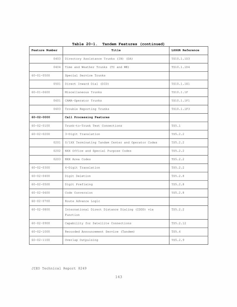
JIEO Technical Report 8249
143
Table 20-1. Tandem Features (continued)Feature Number Title LSSGR Reference
0403 Directory Assistance Trunks (IN) (DA) TS10.1.1D3
0404 Time and Weather Trunks (TI and WE) TS10.1.1D4
60-01—0500 Special Service Trunks
0501 Direct Inward Dial (DID) TS10.1.1E1
60-01-0600 Miscellaneous Trunks TS10.1.1F
0601 CAMA-Operator Trunks TS10.1.1F1
0603 Trouble Reporting Trunks TS10.1.1F3
60-02-0000 Call Processing Features
60-02-0100 Trunk-to-Trunk Test Connections TS5.1
60-02-0200 3-Digit Translation TS5.2.2
0201 0/1XX Terminating Tandem Center and Operator Codes TS5.2.2
0202 NXX Office and Special Purpose Codes TS5.2.2
0203 NXX Area Codes TS5.2.2
60-02-0300 6-Digit Translation TS5.2.2
60-02-0400 Digit Deletion TS5.2.8
60-02-0500 Digit Prefixing TS5.2.8
60-02-0600 Code Conversion TS5.2.8
60-02-0700 Route Advance Logic
60-02-0800 International Direct Distance Dialing (IDDD) via
Function
TS5.2.2
60-02-0900 Capability for Satellite Connections TS5.2.12
60-02-1000 Recorded Announcement Service (Tandem) TS5.4
60-02-1100 Overlap Outpulsing TS5.2.9

JIEO Technical Report 8249
144
Table 20-1. Tandem Features (continued)Feature Number Title LSSGR Reference
60-02-1200 Vacant Code Screening
60-02-1300 Trunk Class Screening
60-02-1400 CAMA Unauthorized Code Screening
60-02-1500 CAMA for Adjacent NPAs
60-03-0000 Tandem Signaling
60-03-0100 Common Channel Signaling
60-03-0200 Interoffice Trunk Signaling TS6.1
60-04-0000 Line and Trunk Test Features
60-04-0100 Test Lines
0101 All 10X-Type Test Lines Used on End Offices
0102 103-Type Tests Line TS9.2.A
0103 104-Type Tests Line TS9.2.B
0104 108-Type Tests Line TS9.2.C
0105 109-Type Tests Line TS9.2.D
60-04-0200 Multiple Trunk Test Capability 9.2.6
60-04-0400 Through Balance Test Facilities
60-04-0500 Selection of Transmission Test Levels (TLP2, TLP3)
60-04-0600 FX Line for ROTL in Tandem Offices
60-04-0700 Two-way Trunk Maintenance 9.2
60-04-0800 Quick “Go or No-Go” Trunk Test
60-04-0900 Continuity Check of the SPCS Voice Path
60-05-0000 Network Management Features
60-05-0100 Automatic Network Management Controls TS16.0
0101 Dynamic Overload Control (DOC) Sensing and Transmit TS16.0
0102 Trunk Reservation
Table 20-1. Tandem Features (continued)
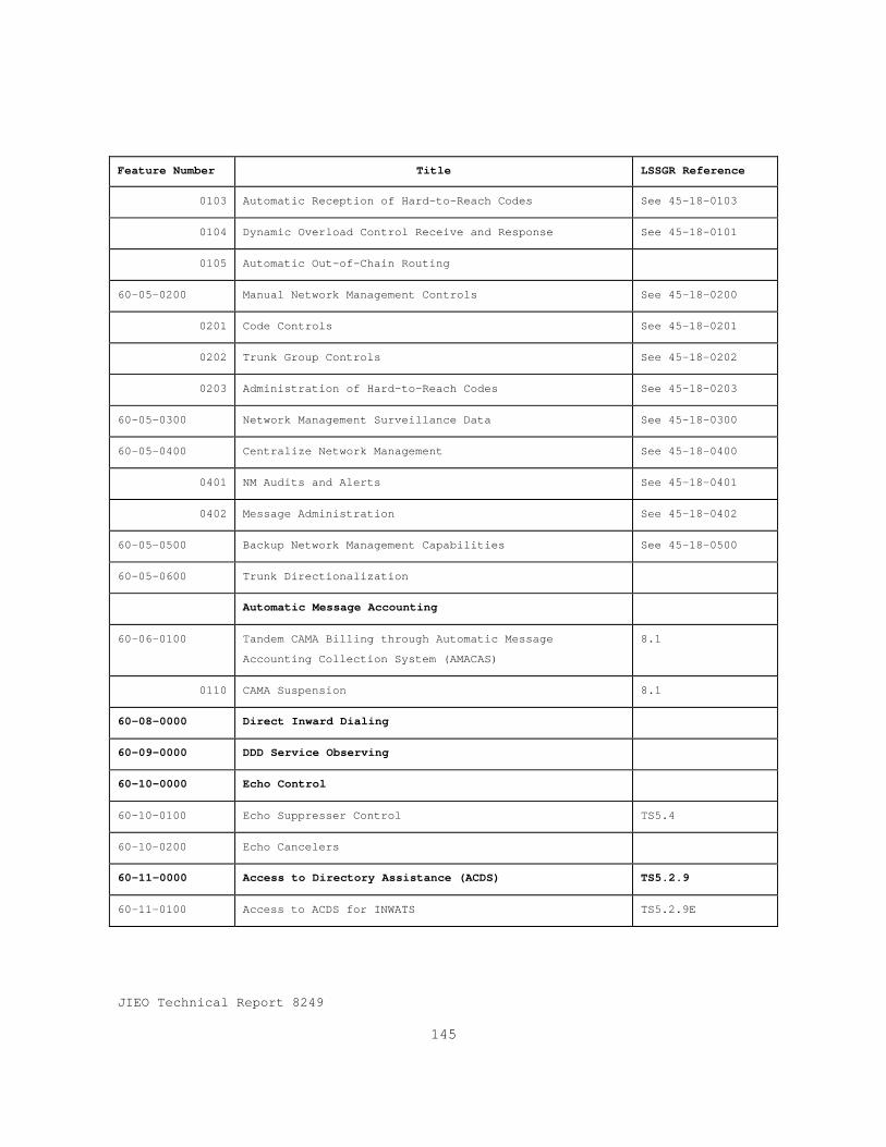
JIEO Technical Report 8249
145
Feature Number Title LSSGR Reference
0103 Automatic Reception of Hard-to-Reach Codes See 45-18-0103
0104 Dynamic Overload Control Receive and Response See 45-18-0101
0105 Automatic Out-of-Chain Routing
60-05-0200 Manual Network Management Controls See 45-18-0200
0201 Code Controls See 45-18-0201
0202 Trunk Group Controls See 45-18-0202
0203 Administration of Hard-to-Reach Codes See 45-18-0203
60-05-0300 Network Management Surveillance Data See 45-18-0300
60-05-0400 Centralize Network Management See 45-18-0400
0401 NM Audits and Alerts See 45-18-0401
0402 Message Administration See 45-18-0402
60-05-0500 Backup Network Management Capabilities See 45-18-0500
60-05-0600 Trunk Directionalization
Automatic Message Accounting
60-06-0100 Tandem CAMA Billing through Automatic Message
Accounting Collection System (AMACAS)
8.1
0110 CAMA Suspension 8.1
60-08-0000 Direct Inward Dialing
60-09-0000 DDD Service Observing
60-10-0000 Echo Control
60-10-0100 Echo Suppresser Control TS5.4
60-10-0200 Echo Cancelers
60-11-0000 Access to Directory Assistance (ACDS) TS5.2.9
60-11-0100 Access to ACDS for INWATS TS5.2.9E

JIEO Technical Report 8249
146
Table 20-1. Tandem Features (concluded)Feature Number Title LSSGR Reference
60-11-0200 Access to ACDS for Directory Assistance TS5.2.9E
60-15-0000 Local Tandem Synchronization TS18.0
60-16-0000 Traffic Measurement (Tandem) TS8.2
60-17-0000 Maintenance Measurements (Tandem) TS9.3
60-18-0000 Administration
60-18-0100 Recent Change States
20.5 Call ProcessingDSN switching systems which require tandem features and
capabilities shall meet the call processing requirements inthe Bellcore LSSGR, Section 20, Paragraph 5 and all itssubparagraphs. In addition tandem switching systems shallmeet the call processing requirements in Section 5 of thisGSCR.
20.6 SignalingDSN switching systems which require tandem features and
capabilities shall meet the signaling requirements in theBellcore LSSGR, Section 20, Paragraph 6 and all itssubparagraphs. In addition tandem switching systems shallmeet the signaling requirements in Section 6 of this GSCR.
20.7 TransmissionDSN switching systems which require tandem features and
capabilities shall meet the transmission requirements in theBellcore LSSGR, Section 20, Paragraph 7 and all itssubparagraphs.
20.8 Automatic Message AccountingDSN switching systems which require tandem features and
capabilities shall meet the AMA requirements in the BellcoreLSSGR, Section 8. DSN tandem switching systems shall meet the

JIEO Technical Report 8249
147
traffic measurements in the Bellcore LSSGR, Section 20,chapter 8, paragraphs 8.2.1, and 8.2.3. Separationsmeasurements in paragraph 8.2.2 are optional and may berequired in site specific contracts.
20.9 Switching System MaintenanceDSN switching systems with tandem functions and capabilities
shall meet the switching system maintenance, circuit andfacility maintenance, and maintenance measurement requirementsin the Bellcore LSSGR, Section 20, paragraphs 9.1, 9.2, and9.3 respectively.
20.10 System InterfacesDSN switching systems shall meet the systems interface
criteria in the Bellcore LSSGR, Section 20, paragraph 10 andall its subparagraphs. In addition DSN switching systemsshall meet the system interface requirements identified inSection 10 of this GSCR, and where applicable, specificationsin the DSN System Interface Criteria, DISA Circular 370-175-13.
20.11 Service StandardsDSN switching systems with tandem features and capabilities
shall meet the service standards in the Bellcore LSSGR,Section 20, Chapter 11. In addition DSN tandem switchingsystems shall provide non-blocking service for FLASH and FLASHOVERRIDE calls.
20.12 ReliabilityDSN switching systems with tandem features and capabilities
shall meet the reliability standards specified in Section 12of this GSCR.
20.13 PowerDSN switching systems with tandem features and capabilities
shall meet the power requirements specified in Section 13 ofthis GSCR.
JIEO Technical Report 8249
148
20.14 EquipmentThe equipment requirements in Section 14 of the Bellcore
LSSGR are not considered requirements. However, they shouldbe used a guidelines in preparing government furnishedfacilities for DSN switching systems.
20.15 Electromagnetic and Electrical EnvironmentDSN switching systems with tandem features and capabilities
shall meet the electromagnetic and electrical environmentrequirements specified in Section 15 of this GSCR.
20.16 Network ManagementDSN switching systems with tandem features and capabilities
shall meet the network management requirements specified inSection 16 of this GSCR.
20.17 System CapacityDSN switching systems with tandem features and capabilities
shall meet the system capacity requirements specified inSection 17 of this GSCR.
20.18 SynchronizationDSN switching systems with tandem features and capabilities
shall meet the synchronization requirements specified inSection 10 of this GSCR.
20.19 DocumentationDSN switching systems with tandem features and capabilities
shall meet the documentation requirements specified in Section19 of this GSCR.

JIEO Technical Report 8249
149
Section 21
Integrated Services Digital NetworkGeneric Requirements
21.1 IntroductionISDN is an evolving digital network technology capable of
providing a wide variety of user applications. National ISDNis the Bellcore recommended implementation of ISDN to providecustomer access to multiple services over a set of uniforminterfaces.
The first step of National ISDN-1 (NI-1)was the initialdeployment of National ISDN in 1992 and addressed the BasicRate Interface (BRI). The second step of National ISDN-2(NI-2) which expanded the BRI interface requirements and addedPrimary Rate Interface (PRI) requirements was introduced in1993. NI-3 introduced an additional set of services foraddressing “mass market” and other market needs.
DSN ISDN generic requirement are based on Bellcore’sNational ISDN documentation summarized in Bellcore SpecialReport, SR-3476, Issue 1, National ISDN 1995 and 1996, June1995.
21.2 DSN Generic ISDN Features and InterfaceDescriptions
DSN switching systems shall provide the ISDN BRI, PRI,Packet Data, Operations, and Cross Platform capabilities shownin Tables 21-1 through 21-8 and described in Bellcore SR-3476.

JIEO Technical Report 8249
150
Table 21-1. BRI Access, Call Control, and Signaling
SR-3476 Reference Feature or Capability
2.1.1.1 ISDN BRI Layer 12.1.1.2 4:1 Time Division Multiplex Method for ISDN Basic Access2.1.1.3 ISDN BRI Layer 22.1.1.42.1.1.4.1
BRI Circuit-Mode Call ControlBasic Call Control
2.1.1.5 BRI Terminal Initialization2.1.1.6 Service Profile Identifier2.1.1.7 Parameter Downloading2.1.1.8 Default Services for Terminals2.1.1.9 BRI Interworking with SS72.1.1.102.1.1.10.12.1.1.10.2
ISDN BRI PacketUser Originated, On-Demand B-Channel PacketConditional Notification
Table 21-2. Uniform Interface Configurations for BRIs
SR-3476 Reference Feature or Capability
2.1.2 Uniform Interface Configurations for BRI’sSingle User with Multiple ApplicationsTwo Users Sharing a BRI
2.1.2.1 More than 2 B-Channel Terminals on a BRI(Passive Bus)
2.1.2.2 Associated Group Indicator2.1.2.3 DN Sharing over Multiple Call Types on and Integrated
Terminal2.1.2.4 Non-Initializing Terminals
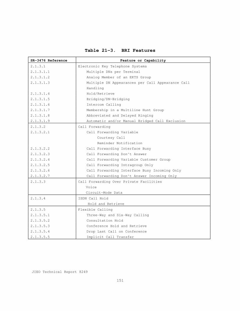
JIEO Technical Report 8249
151
Table 21-3. BRI Features
SR-3476 Reference Feature or Capability
2.1.3.1 Electronic Key Telephone Systems2.1.3.1.1 Multiple DNs per Terminal2.1.3.1.2 Analog Member of an EKTS Group2.1.3.1.3 Multiple DN Appearances per Call Appearance Call
Handling2.1.3.1.4 Hold/Retrieve2.1.3.1.5 Bridging/DN-Bridging2.1.3.1.6 Intercom Calling2.1.3.1.7 Membership in a Multiline Hunt Group2.1.3.1.8 Abbreviated and Delayed Ringing2.1.3.1.9 Automatic and/or Manual Bridged Call Exclusion2.1.3.2 Call Forwarding2.1.3.2.1 Call Forwarding Variable
Courtesy CallReminder Notification
2.1.3.2.2 Call Forwarding Interface Busy2.1.3.2.3 Call Forwarding Don’t Answer2.1.3.2.4 Call Forwarding Variable Customer Group2.1.3.2.5 Call Forwarding Intragroup Only2.1.3.2.6 Call Forwarding Interface Busy Incoming Only2.1.3.2.7 Call Forwarding Don’t Answer Incoming Only2.1.3.3 Call Forwarding Over Private Facilities
VoiceCircuit-Mode Data
2.1.3.4 ISDN Call HoldHold and Retrieve
2.1.3.5 Flexible Calling2.1.3.5.1 Three-Way and Six-Way Calling2.1.3.5.2 Consultation Hold2.1.3.5.3 Conference Hold and Retrieve2.1.3.5.4 Drop Last Call on Conference2.1.3.5.5 Implicit Call Transfer

JIEO Technical Report 8249
152
Table 21-3. BRI Features (continued)SR-3476 Reference Feature or Capability
2.1.3.6 Additional Call Offering - Unrestricted2.1.3.6.1 Notification and Call Reference Busy Limits2.1.3.7 Calling Number Identification Services for BRI2.1.3.7.1 Delivery of Network Provided Calling Number2.1.3.7.2 Privacy of Calling Number2.1.3.7.3 Delivery of Redirecting Number2.1.3.7.4 Privacy of Redirecting Number2.1.3.7.5 Delivery of Redirecting Reason2.1.3.7.6 Ability to Segregate Number Delivery on Intra-BBG/Inter-
BBG Basis2.1.3.8 ISDN Display Service
Protocol and ProceduresUniform Text (for NI-2 Uniform Services)
2.1.3.9 Automatic Callback Intraswitch2.1.3.10 Message Service
Message Waiting Indicator2.1.3.11 Multiline Hunt Group
Analog Members in Hunt Group2.1.3.11.1 Linear Hunting2.1.3.11.2 Circular Hunting2.1.3.11.3 Uniform Hunting2.1.3.11.4 Stop Hunt2.1.3.11.5 Make Busy2.1.3.12 Basic Business Group
Inclusion of Non-ISDN Circuit-Mode LinesInclusion of Non-ISDN Circuit-Mode Private Facilities
2.1.3.12.1 Semi-Restricted Originating Access2.1.3.12.2 Semi-Restricted Terminating Access2.1.3.12.3 Semi-Restricted Line2.1.3.12.4 Fully-Restricted Originating Access2.1.3.12.5 Fully-Restricted Terminating Access2.1.3.12.6 Fully-Restricted Line2.1.3.12.7 Denied Originating
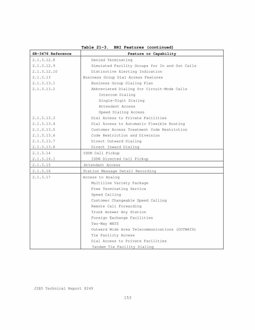
JIEO Technical Report 8249
153
Table 21-3. BRI Features (continued)SR-3476 Reference Feature or Capability
2.1.3.12.8 Denied Terminating2.1.3.12.9 Simulated Facility Groups for In and Out Calls2.1.3.12.10 Distinctive Alerting Indication2.1.3.13 Business Group Dial Access Features2.1.3.13.1 Business Group Dialing Plan2.1.3.13.2 Abbreviated Dialing for Circuit-Mode Calls
Intercom DialingSingle-Digit DialingAttendant AccessSpeed Dialing Access
2.1.3.13.3 Dial Access to Private Facilities2.1.3.13.4 Dial Access to Automatic Flexible Routing2.1.3.13.5 Customer Access Treatment Code Restriction2.1.3.13.6 Code Restriction and Diversion2.1.3.13.7 Direct Outward Dialing2.1.3.13.8 Direct Inward Dialing2.1.3.14 ISDN Call Pickup2.1.3.14.1 ISDN Directed Call Pickup2.1.3.15 Attendant Access2.1.3.16 Station Message Detail Recording2.1.3.17 Access to Analog
Multiline Variety PackageFree Terminating ServiceSpeed CallingCustomer Changeable Speed CallingRemote Call ForwardingTrunk Answer Any StationForeign Exchange FacilitiesTwo-Way WATSOutward Wide Area Telecommunications (OUTWATS)Tie Facility AccessDial Access to Private FacilitiesTandem Tie Facility Dialing

JIEO Technical Report 8249
154
Table 21-3. BRI Features (continued)SR-3476 Reference Feature or Capability
2.1.3.17 (continued) Radio Paging AccessCode CallingLoudspeaker PagingSelective Control of FacilitiesDeluxe QueuingOff-Hook QueuingOn-Hook QueuingPost-Queue RoutingPriority QueuingService ProtectionAutomatic Route SelectionDeluxe Automatic Route SelectionAutomatic Alternate RoutingUniform NumberingOff-Network-to-On-Network ConversionOn-Network-to-Off-Network ConversionFacility Restriction LevelAlternate Facility Restriction LevelExpensive Route Warning ToneManual/Time-of-Day Routing ControlAuthorization Codes for Automatic Flexible Routing (AFR)Account Codes for AFRCustomer Dialed Account RecordingAttendant Access to Code CallingAttendant ConferenceNight Service -AttendantPower Failure Transfer - AttendantDial Through AttendantAttendant Tie Trunk Busy VerificationBasic Emergency Service (911)Tracing of Terminating CallsTandem Call Tracing

JIEO Technical Report 8249
155
Table 21-3. BRI Features (concluded)SR-3476 Reference Feature or Capability
2.1.3.17 (concluded) Trace of a Call In ProgressSeries CompletionAutomatic Callback (Interswitch)Automatic RecallBulk Calling Line IdentificationCustomer Originated TraceScreen List EditingSelective Call AcceptanceSelective Call Forwarding
Selective Call Rejection2.1.3.18 ISDN Calling Name Identification Services2.1.3.19 Limitations and Restrictions for 911 Calls
Hold Not Allowed for a 911 CallAdd a 911 Call to a Conference
2.1.3.20 Remote Access to ISDN Call ForwardingMilitary Unique Features
Multi-Level Precedence and Preemption (MLPP)(GSCRSection 2, paragraph 2.2.1)Community Of Interest (GSCR, Section 2, paragraph 2.2.2)Preset Conferencing (GSCR, Section 2, paragraph 2.2.3)

JIEO Technical Report 8249
156
Table 21-4. PRI Access, Call Control, and Signaling
SR-3476 Reference Feature or Capability
2.2.1.1 PRI Layer 12.2.1.2 PRI Layer 2 (Circuit)2.2.1.3 PRI Call Control and Signaling2.2.1.3.1 Basic Call Control for Circuit Mode Calls2.2.1.3.2 Multiple DS1 Facilities Controlled by a Single D-Channel2.2.1.3.3 Access to Selected Primary Rate Services on a Per-Call
Basis2.2.1.3.4 PRI Interworking with CCS72.2.1.4 PRI Packet-Mode Call Control
Military Unique Features/Supplemental ServicesMulti-Level Precedence and Preemption (MLPP)Community Of InterestPreset Conferencing
Table 21-5. PRI Features
SR-3476 Reference Feature or Capability
2.2.2.1 Calling Number Identification Services2.2.2.1.1 Delivery of Network Provided Calling Number2.2.2.1.2 Privacy of Calling Number2.2.2.1.3 Screening Functions2.2.2.2 Call-by-Call Service Selection
FXNon-ISDN TieINWATSOUTWATSNon-ISDN ETN
2.2.2.3 Interworking with Private NetworksMilitary Unique Features/Supplemental Services
Multi-Level Precedence and Preemption (MLPP)Community Of InterestPreset Conferencing

JIEO Technical Report 8249
157
Table 21-6. Packet Data Features and Capabilities
SR-3476 Reference Feature or Capability
2.3.1 PPSN Call Control and Features - X.25 Features2.3.1.1 Closed User Groups (CUG),CUG Outgoing Access, CUG
Incoming Access2.3.1.3 Recognized Private Operating Administration (RPOA)2.3.1.5 CCITT DTE Facilities2.3.2 PPSN Call Control and Features X.75 and X.75’ Utility
Support2.3.2.1 All X.75 Utilities in Minimal Subset2.3.2.2 Multilink Procedures on X.75/X.75’2.3.2.3 Support of X.75 End Office Connections2.3.2.4 Selective Support of X.75’ Utilities
X.75 Utilities on X.75’Access CharacteristicsX.75 Interface IdentifierClearing Subnetwork IdentificationTransmit Subnetwork Count
2.3.3 Packet Numbering and Routing2.3.3.1 Packet Mode Data Routing & Digit Analysis Requirements2.3.3.2 Numbering Plan Interworking per TR-448 and TR-301.2.3.4 User-to-User with Call Control (Packet)2.3.4.1 Fast Select, Fast Select Acceptance2.3.4.2 16 Octets of data in call request2.3.5 ISDN X.25 Supplementary Services2.3.5.1 ISDN Local Charging Prevention2.3.5.2 One-Way Logical Channel Outgoing/Incoming2.3.5.3 Incoming/Outgoing Calls Barred2.3.5.4 Default Throughput Class Alignment2.3.5.5 Nonstandard Default Packet Sizes2.3.5.6 Nonstandard Default Window Sizes2.3.5.7 Flow Control Parameter Negotiation2.3.5.8 Throughput Class Negotiation2.3.5.9 Transit Delay
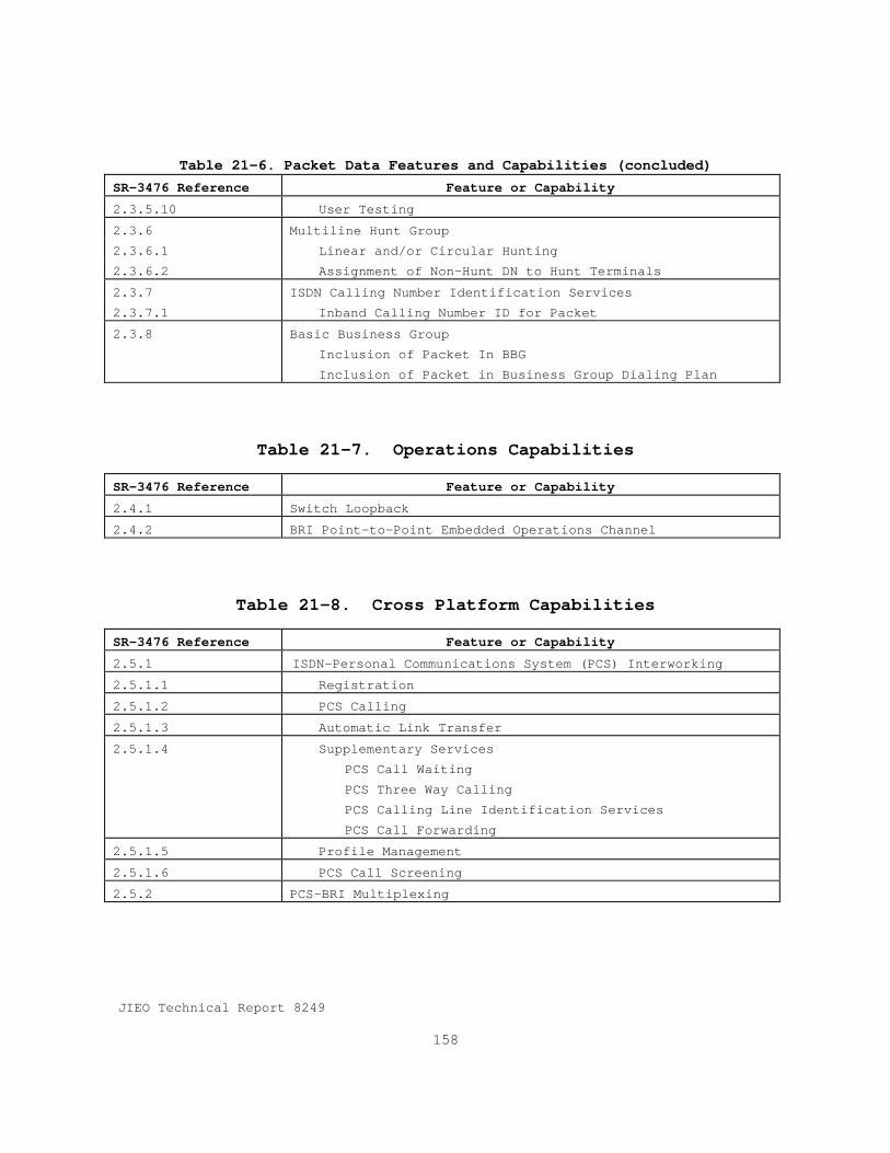
JIEO Technical Report 8249
158
Table 21-6. Packet Data Features and Capabilities (concluded)SR-3476 Reference Feature or Capability
2.3.5.10 User Testing2.3.6 Multiline Hunt Group2.3.6.1 Linear and/or Circular Hunting2.3.6.2 Assignment of Non-Hunt DN to Hunt Terminals2.3.7 ISDN Calling Number Identification Services2.3.7.1 Inband Calling Number ID for Packet2.3.8 Basic Business Group
Inclusion of Packet In BBGInclusion of Packet in Business Group Dialing Plan
Table 21-7. Operations Capabilities
SR-3476 Reference Feature or Capability
2.4.1 Switch Loopback2.4.2 BRI Point-to-Point Embedded Operations Channel
Table 21-8. Cross Platform Capabilities
SR-3476 Reference Feature or Capability
2.5.1 ISDN-Personal Communications System (PCS) Interworking2.5.1.1 Registration2.5.1.2 PCS Calling2.5.1.3 Automatic Link Transfer2.5.1.4 Supplementary Services
PCS Call WaitingPCS Three Way CallingPCS Calling Line Identification ServicesPCS Call Forwarding
2.5.1.5 Profile Management2.5.1.6 PCS Call Screening2.5.2 PCS-BRI Multiplexing

JIEO Technical Report 8249
159
21.3 ISDN Supplementary ServicesDSN switching systems shall be capable of providing MLPP,
conference calling, user to user signaling, call hold, callwaiting, call deflection, normal call transfer, explicit calltransfer, hotline, and preset conference ISDN supplementaryservices.
21.3.1 Multilevel Precedence and PreemptionMLPP service requirements shall be as defined in Sections 1
through 4 of ANSI T1.619a. The user-to-network signalingprocedures (called the DSS1 stage 3 description) for the MLPPfeature shall be as specified in Section 6, Annex A (onSpecification and Description Languages (SDLs)), Annex C (onthe invoke and return result components used with the MLPP LFBquery), and Annex D (on tones and alerting cadences for MLPP)of ANSI T1.619a.
21.3.2 Conference CallingISDN conference calling service shall be provided in
accordance with ANSI T1.647-1995, ISDN Conference CallingSupplementary Service.
21.3.3 User-to-User SignalingISDN user-to-user signaling service shall be provided in
accordance with ANSI T1.621-1992, ISDN User-to-User SignalingSupplementary Service.
21.3.4 Call HoldISDN call hold service shall be provided in accordance with
ANSI T1.616-1992, ISDN Call Hold Supplementary Service.
21.3.5 Call WaitingISDN call waiting service shall be provided in accordance
with ANSI T1.613-1992, ISDN Call Waiting SupplementaryService.

JIEO Technical Report 8249
160
21.3.6 Normal Call TransferISDN normal call transfer service shall be provided in
accordance with ANSI T1.632-1993, ISDN Normal Call TransferSupplementary Service.
21.3.7 Explicit Call TransferISDN explicit call transfer service shall be provided in
accordance with ANSI T1.643-1995, ISDN Explicit Call TransferSupplementary Service.
21.3.8 Call DeflectionISDN call deflection service shall be provided in accordance
with ANSI T1.642-1993, ISDN Call Deflection SupplementaryService.
21.3.9 Community of Interest (COI)DSN COI is a grouping of DSN users within the DSN who
generate the majority of their traffic in calls to oneanother. The DSN users within a COI (called COI members) maybe confined to a limited geographical area or may be dispersedworldwide. The COI members may be restricted to callingwithin the COI, or have the capability of calling outside theCOI. Nonmembers may be prevented from calling the COI membersor may be capable of entering the COI only with a precedencecall. Designated DSN users may be included as members of twoor more COIs. As an option, members of a COI may be capableof exercising, for calls within the COI, a precedence levelhigher than that permitted to the calls outside the COI. Aminimum of 10 COIs shall be provided. The Business Groupservice developed in the T1S1 Technical Subcommittee, may beused to provide the COI feature.
21.3.10 Hotline ServiceHotline service shall allow the user to automatically
initiate a call to a previously designated user by initiatinga service request and/or to act as a receiver for Hotlineoriginated calls and/or calls from designated parties on ascreening list. Hotline service shall allow users to placecalls without providing, in the call setup request, the called

JIEO Technical Report 8249
161
party information required by the network to route the call.Instead, the information is stored in the network by priorsubscription. The service shall also allow terminatingrestrictions to be provided to ensure that certain Hotlinesubscribers only receive calls from other specified users. TheHotline service shall be provided on a subscription basis tospecific users and may be withdrawn for administrative reasonsor at the request of the subscriber.
The Hotline subscriber with the originating Hotline optionshall invoke the service by sending a normal call setuprequest to the network but without destination information.The network shall use the subscribed information to processthe call and establish it according to the normal networkprocedures. The network shall also indicated that the call isa Hotline originated call.
At the called user with a Terminating Restriction option,the restriction portion of the service shall be invokedwhenever a terminating call is received by the network of thecalled user.
If the called user is subscribed to the TerminatingRestriction by list option only, the network searches thescreening list for the calling user’s number. If the callinguser’s number is provided and found on the screening list, thenetwork shall complete the call. If the calling user’s numberis not provided or if the provided number is not found on thescreening list, the network shall block the call, provide theappropriate intercept treatment, and log the attempt.
Hotline service is offered to the user with the followingsubscription options.
21.3.10.1 Protected Hotline CallingThe user may receive calls only from a specified list of
parties and may originate calls to a specified destinationonly, called the Designated Called Party (DCP).
21.3.10.2 Pair Protected Hotline CallingEach of the two designated users can only call each other
and no third party can call either.

JIEO Technical Report 8249
162
21.3.10.3 Unprotected Hotline CallingThe user may originate calls to a specified destination only
(i.e., the DCP) but may receive calls from any party includingthe DCP.
21.3.10.4 Protected Hotline ReceivingThe user may receive calls only from a list of parties but
may originate calls to any party.
21.3.11 Preset Conference CallingThe ISDN supplemental service preset conference calling is
an optional feature that may be specified by the orderingdepartment or agency in site specific contracts. The presetconference calling feature shall allow the served user toquickly establish a conference call with a predefined list ofparties that is stored in the network using a presetidentification. Upon invocation of a preset conference, thenetwork shall validate the request, determine the confereesthat are associated with the call, dial each conferee, inparallel, and establish the conference.
As each conferee responds to the preset conference call, thenetwork shall provide the responding conferee with a presetconference notification. This notification will inform theconferees that they are about to take part in a presetconference call. Once the conference is established, theprocedures for adding new conferees, dropping conferees, andterminating a conference shall be available to the conferencecontroller.
21.3.11.1 ProceeduresThe preset conference calling supplementary services by
shall be subscribed to by prior arrangement.
Withdrawal of the service is accomplished by the serviceprovider upon request by the subscriber or for serviceprovider reasons.
Conference calling shall be provided with subscriptionoptions and associated values. The options apply separatelyto each ISDN number and bearer service combination or to eachterminal service profile or to each interface. The optionsare shown in Table 21-9.

JIEO Technical Report 8249
163
Table 21-9. Preset Conference Subscription Options
Subscription Option Values
Maximum conference size (Note 1) N, where 3 ≤ N ≤ 127Default conference size M, where 3 ≤ M ≤ NNumber of Preset Identifications Up to the maximum dependent upon the
service provider.For each Preset ID:
Preset ID ISDN number of the primary bridgeConferee/alternate conferee addresses ISDN numbersNotifications to served user (Note 2) If Yes (Optional notifications in Notes
3 and 4)No
Notifications to conferee Yes (Note 5)1 - The maximum conference size is a service provider option2 - Notifications may include information such as names and some otherinformation regarding confereees3 - These notifications are optional: conferee has responded, conferee callattempt has been terminated for lack of response, conferee call has beenterminated by the conferee, conferee call attempt has been diverted to alternateconferee, conferee call attempt has been diverted to alternate conferee, confereeis added to the conference, conferee has been dropped from the conference,conferee has been preempted by a higher precedence call, conference isdisconnected.4 - Served user also receives the following notifications: Preset conference isactive, add request is denied, and drop request is denied, conferee has beenpreempted by a higher precedence call.5 - Conferees shall receive the following notifications: preset conference callannouncement, and preset conference is active.
Once all conferees or alternates conferees have responded orhave had their call attempts terminated, the preset conferencecall shall be established with the mandatory conference activenotification to the served user and the connected conferees.
The served user shall be able to terminate the conferencenotification and force the preset conference to be establishedbefore all conferees have either responded or have beenterminated. The responded conferees at the time theconference is forced shall be connected to the conference andreceive the conference active notification. The presetconference call setup procedure continues for conferees that

JIEO Technical Report 8249
164
had not responded when the conference was forced. In thiscase the conferees will be added to the conference as theyrespond and receive a notification that the conference isactive and the served user may receive an optionalnotification that a conferee has been added.
21.3.11.2 Managing Individual Conferences.Once the conference has been established, the conference
controller, generally the served user, has the followingoptions for managing conferees in association with theconference on which he/she is active.
a. Add a new conferee: Once the preset conference isestablished the served user shall be able to add newconferees to the conference. The number of conferees thatcan be added to an established conference is 5.
b. Drop a conferee: The conference controller may requestthat a specified conferee (indicated by the Party ID) bedisconnected from the conference and the conferencecontroller’s association with that conferee be eliminatedcompletely, all conferees still active on the conferencewill be notified of the successful drop operation.
c. Isolate a conferee: The conference controller mayrequest that a specified conferee (indicated by the PartyID) be prevented from communicating with the conference butnot removed from it. This does not affect the state (e.g.Active or Held) of the specified conferee’s access channels(e.g. B-channels) which are nominally under the control ofthe specified conferee. All conferees, including theisolated party, shall be notified of the successful isolateoperation. It shall be possible for the conferencecontroller to isolate more than one conferee from aconference call that contains 2 or more conferees. In fact,all conferees could be isolated from the conference by theconference controller.
d. Reattach a conferee: The conference controller mayrequest that a specified conferee (indicated by the PartyID) be reattached to the conference. Successful executionof this command permits a previously isolated conferee toagain converse with all other conferees that are connected

JIEO Technical Report 8249
165
to the conference. This does not affect the state (e.g.active or held) of the specified conferee’s access channels(e.g. B-channels) which are nominally under the control ofthe specified conferee. All conferees, including thereattached party, shall be notified of the successfulreattach operation.
e. Split a conferee: The conference controller may requestthat a specified conferee (indicated by the Party ID) beremoved from the conference (indicated by the ConferenceID), but remain connected to the conference controller.Execution of this request requires that the controllerestablish a new call, since the remote user is no longerassociated with the conference call. All conferees,including the split party, shall be notified of thesuccessful split operation upon establishment of the newcall.
f. Terminate the conference: The conference controller mayexplicitly request that a conference be terminated, i.e.
• that every party associated with the particularconference be disconnected;
• that all conference resources be de-allocated; and• that all knowledge of the conference call, including the
Call ID, be removed.21.3.11.3 Conferee ActionsIn the active state of the conference, and conferee may:
a. Hold and retrieve the conferee’s connection to theconference as per Call Hold supplementary serviceprocedures;
b. Disconnect the conferee’s connection to the conference asper basic call control call clearing procedures. Anindication is provided to the controller and the activeconferees;
c. Invoke the Conference Calling supplementary service(i.e., on his/her connection t the existing conference,thus forming a “chain” of conference).
21.3.11.4 Interworking Considerations

JIEO Technical Report 8249
166
No interworking situations exist over and above thoserequired for communications with respect to the basic service.The conference controller shall be an ISDN user. Theoperation of this service is unaffected by the nature (i.e.,ISDN or non-ISDN) of the conferees’ connections. The deliveryof notifications associated with Preset Conference Calling tonon-ISDN conferees may not be possible.
21.3.11.5 Capabilities for ChargingThe service provider shall be able to charge accurately for
this service.
21.3.11.6 Interaction With Other Supplementary ServicesIf a conferee uses, during the conference, a supplementary
service or other function that generates a notification to theconference controller, this notification shall be sent to theconference controller with the Party ID of the party itapplies to. Interactions with other supplementary servicesshall be as described in ANSI T1.647, paragraph 4.5.
21.3.11.7 Functional Capabilities and Information FlowsFunctional capabilities and information flows shall be as
described in ANSI T1.647, paragraph 5.
21.3.11.8 Switching and Signaling SpecificationSwitching and signaling specifications at the user/network
interface shall be as described in ANSI T1.647 as modified byuser to network signaling is Section 6 of this specification.
21.3.11.9 Switching and Signaling At InterexchangeInterfaces.Switching and signaling specifications at the interexchange
interface shall be as described in ANSI T1.647 as modified byuser to network signaling is Section 6 of this specification.
21.3.11.10 Protocol Interworking21.3.11.10.1 CCS7/DSS1. When and IS-UP notification
indicator parameter is received at the destination EO, itshall be mapped as a DSS1 Notification indicator informationelement in a NOTIFY message.
21.3.11.10.2 ISDN/non-ISDN. No notification is passed tothe conferees if they are non-ISDN users.

JIEO Technical Report 8249
167
Glossary
TERM Definition
ABS Alternate Billing Service
ABSBH Average Busy Season Busy Hour
ACC Automatic Congestion Controls
ACG Automatic Call Gap
AIN Advanced Intelligent Network
AMA Automatic Message Accounting
AMI Alternate Mark Inversion
ANSI American National Standards Institute
AO&M/NM Administration, Operations, and Maintenance/NetworkManagement
ASD/C3I Assistant Secretary of Defense for Command, Control,Communications, and Intelligence
ATB All Trunks Busy
BAF Bellcore AMA Format
BCC Bellcore Client Companies
BNEA Busy Not Equipped Announcement
BPA Blocked Precedence Announcement
BRI Basic Rate Interface
CAMA Centralized Automated Message Accounting
CAS Centralized Attendant Service
CLASS Custom Local Area Signaling Services
CCS7 Common Channel Signaling System No. 7
CO Central Office
COI Community of Interest
CPE Customer Premises Equipment

JIEO Technical Report 8249
168
CS Circuit Switched
DCAC Defense Communications Agency Circular
DF Distribution Frame
DOC Dynamic Overload Control
DPC Destination Point Code
DISA Defense Information Systems Agency
DISN Defense Information Systems Network
DoD Department of Defense
DoDD DoD Directive
DP Dial Pulse
DPAS Digital Patch and Access System
DRSN Defense Red Switch Network
DS1 Digital Signal 1
DSN Defense Switched Network
DSS1 Digital Subscriber Signaling System No. 1
DTMF Dual Tone Multi-Frequency
EN End Office Node
EOS End Office Switch
ESP Essential Service Protection
F FLASH
FO FLASH OVERRIDE
FTS2000 Federal Telecommunications System 2000
GOS Grade of Service
GSCR Generic Switching Center Requirements
HTR Hard To Reach
I IMMEDIATE
IAM Initial Address Message
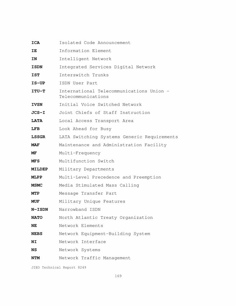
JIEO Technical Report 8249
169
ICA Isolated Code Announcement
IE Information Element
IN Intelligent Network
ISDN Integrated Services Digital Network
IST Interswitch Trunks
IS-UP ISDN User Part
ITU-T International Telecommunications Union -Telecommunications
IVSN Initial Voice Switched Network
JCS-I Joint Chiefs of Staff Instruction
LATA Local Access Transport Area
LFB Look Ahead for Busy
LSSGR LATA Switching Systems Generic Requirements
MAF Maintenance and Administration Facility
MF Multi-Frequency
MFS Multifunction Switch
MILDEP Military Departments
MLPP Multi-Level Precedence and Preemption
MSMC Media Stimulated Mass Calling
MTP Message Transfer Part
MUF Military Unique Features
N-ISDN Narrowband ISDN
NATO North Atlantic Treaty Organization
NE Network Elements
NEBS Network Equipment-Building System
NI Network Interface
NS Network Systems
NTM Network Traffic Management

JIEO Technical Report 8249
170
OCONUS Outside Continental U.S.
OMAP Operation and Maintenance Application Part
OS Operations Systems
OTGR Operations Technology Generic Requirements
P PRIORITY
PALA Precedence Access Limitation Announcement
PAR Peak-to-Average Ratio
PAT Precedence Access Threshold
PBX Private Branch Exchange
PCM Pulse-code Modulation
PCR Preventive Cyclic Retransmission
PCW Precedence Call Waiting
PL Precedence Level
PL/CA Precedence Level and Calling Area
PNID Precedence Network Inward Dial
PPSN Public Packet Switched Network
PRI Primary Rate Interface
PSN Public Switched Network
PTT Post, Telephone, and Telegraph
RLT Release Link Trunk
RSU Remote Switch Unit
SCCP Signaling Connection Control Part
SDL Specification and Description Language
SILC Selective Incoming Load Control
SLS Signaling Link Selection
SMDS Switched Multi-megabit Data Services
SONET Synchronous Optical Network
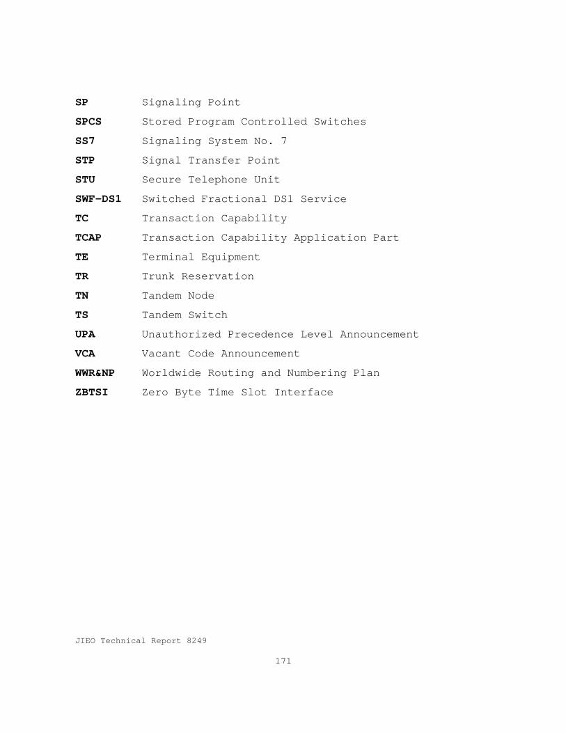
JIEO Technical Report 8249
171
SP Signaling Point
SPCS Stored Program Controlled Switches
SS7 Signaling System No. 7
STP Signal Transfer Point
STU Secure Telephone Unit
SWF-DS1 Switched Fractional DS1 Service
TC Transaction Capability
TCAP Transaction Capability Application Part
TE Terminal Equipment
TR Trunk Reservation
TN Tandem Node
TS Tandem Switch
UPA Unauthorized Precedence Level Announcement
VCA Vacant Code Announcement
WWR&NP Worldwide Routing and Numbering Plan
ZBTSI Zero Byte Time Slot Interface

