jie song , k.t. tse *, and jiming xie - iasem - index · pdf filedynamic characteristics of...
TRANSCRIPT
Dynamic characteristics of wind-excited linked twin buildings based on a 3-Dimensional analytical model
Jie Song1) , K.T. Tse2)*, and Jiming Xie3)
1),2) Department of Civil and Environmental Engineering, HKUST, Hong Kong, China 3) College of Civil Engineering and Architecture, Zhejiang University, Hangzhou, China
ABSTRACT The present work investigates the effects of structural links on the modal properties
and wind-induced responses of a linked building system (LBS) by using a three-dimensional analytical model. The LBS in this work refers to a system consisting of twin buildings horizontally connected by structural links such as skybridges or skygardens. The analytical model for the LBS is formed by assembling the rigid diaphragm model of the building and the beam model of each link in a matrix formulation. Through the analytical model and measured wind force data, the modal properties and wind-induced structural responses are computed for LBS with different links to investigate the effects of link parameters, including mass, axial stiffness, bending stiffness, and location. Some critical link parameters are summarized, which can be used as guidance for engineering designs of LBS.
1. Introduction
There is a trend to design tall buildings in close proximity as a linked building system (LBS), i.e. a system consisting of several buildings horizontally connected by links such as skybridges, skygardens, etc (Xie and Irwin 2001; Lee et al. 2010). The Petronas Twin Towers in Kuala Lumpur and the Marina Bay Sands Hotel in Singapore are two notable examples that illustrate this trend. These LBSs are usually very tall to achieve a grand appearance. As such, wind-induced response is one of the primary concerns in design practice as structural links tend to further complicate the design wind loads that are already complex and significant for skyscrapers.
In order to calculate wind-induced responses of the LBS, it is necessary to develop a three-dimensional (3D) analytical model of the LBS incorporating the effect of link. To this end, Lim’s group (Lim 2009; Lim et al. 2011) proposed a simplified six-degree-of-freedom analytical model for twin buildings connected by a skybridge. Although this model is straightforward to show the effect of link, it should be mentioned that this model is formed by employing assumed structural mode shapes that are independent of link properties. In other words, the effect of link on the mode shapes of the system is not considered. It was reported that mode shapes of the LBS could be changed significantly by a structural link (Huang 2001). If the assumed mode shape deviates
1) Graduate Student 2) Professor, Corresponding author 3) Professor
considerably from the actual one, the structural frequency of the system will be considerably overestimated according to Rayleigh’ method (Clough and Penzien 1993).Unreliable frequency and mode shape will introduce extra uncertainties in the estimation of the resultant wind-induced responses. Therefore, it is worthwhile and necessary to formulate an analytical evaluation model of the LBS by eliminating the assumption about the mode shapes.
The present work investigates the effects of link on the modal properties and the wind-excited structural responses of the LBS by developing a 3D analytical evaluation model for two adjacent buildings connected by several structural links. First, an analytical evaluation model of the LBS incorporating structural motions in the three directions was formulated in a matrix-form. Subsequently, the effects of link on the modal properties and wind-induced responses of the system were examined. The main findings were summarized in the conclusions.
2. Analytical Model of Structurally-coupled Twin buildings
2.1 Assumptions
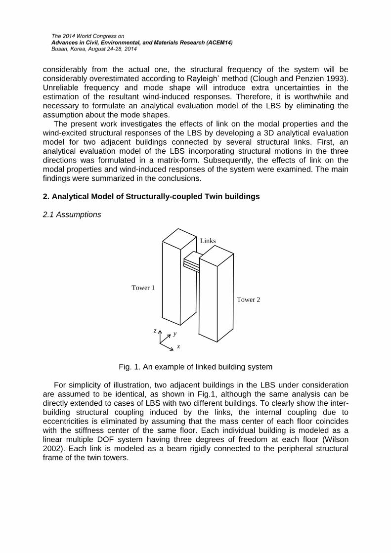
Fig. 1. An example of linked building system
For simplicity of illustration, two adjacent buildings in the LBS under consideration are assumed to be identical, as shown in Fig.1, although the same analysis can be directly extended to cases of LBS with two different buildings. To clearly show the inter-building structural coupling induced by the links, the internal coupling due to eccentricities is eliminated by assuming that the mass center of each floor coincides with the stiffness center of the same floor. Each individual building is modeled as a linear multiple DOF system having three degrees of freedom at each floor (Wilson 2002). Each link is modeled as a beam rigidly connected to the peripheral structural frame of the twin towers.
Tower 2
Tower 1
Links
x
yz
2.2. Equations of Motion Let each building in the LBS have m floors interconnected by n (n ≤ m) links at n
arbitrary floors, the LBS can then be taken as a 6m degrees of freedom system. Accordingly, the equations of motion for the system subjected to wind loads can be written as
L LM M D CD Κ Κ D F (1)
where M, C, and K are the mass, damping, and stiffness matrices of the twin buildings without links, respectively; ML and KL are the additional mass and stiffness matrices due to the existence of links, which are given later; F= {F1x, F1y, F1θ, F2x, F2y, F2θ} T is the external wind force vector, in which Fgs (g=1, 2; s=x, y or θ) is the wind force on tower g in the s direction; D={D1x, D1y, D1θ, D2x, D2y, D2θ}T is the displacement response vector. The details of each matrix are listed as follows:
1 1 1
2 2 26 6 6 6 6 6m m m m m m
M 0 C 0 K 0M C K
0 M 0 C 0 K (2)
1 2 1 2
3 3 3 3
x xx x
y yy y
x ym m m m
M 0 0 K 0 KM M 0 M 0 K K 0 K K
0 0 J K K K(3)
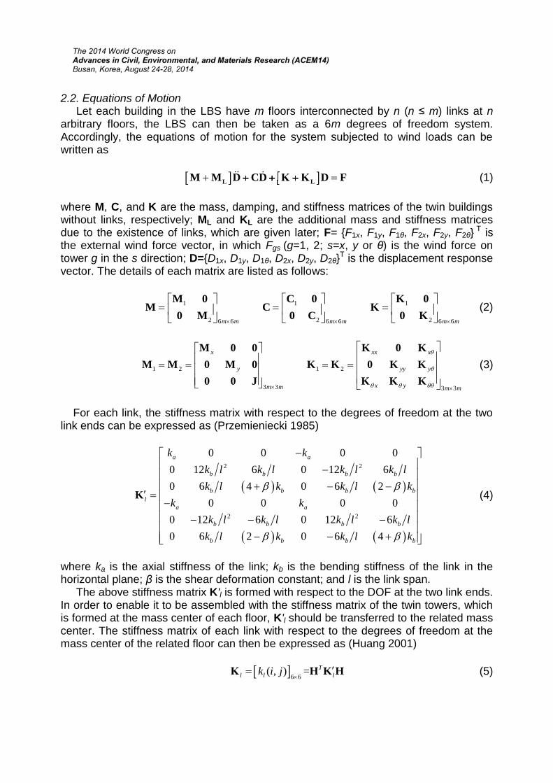
For each link, the stiffness matrix with respect to the degrees of freedom at the two link ends can be expressed as (Przemieniecki 1985)
2 2
2 2
0 0 0 00 12 6 0 12 60 6 4 0 6 2
0 0 0 00 12 6 0 12 60 6 2 0 6 4
a a
b b b b
b b b bl
a a
b b b b
b b b b
k kk l k l k l k lk l k k l k
k kk l k l k l k l
k l k k l k
K (4)
where ka is the axial stiffness of the link; kb is the bending stiffness of the link in the horizontal plane; β is the shear deformation constant; and l is the link span.
The above stiffness matrix K'l is formed with respect to the DOF at the two link ends. In order to enable it to be assembled with the stiffness matrix of the twin towers, which is formed at the mass center of each floor, K'l should be transferred to the related mass center. The stiffness matrix of each link with respect to the degrees of freedom at the mass center of the related floor can then be expressed as (Huang 2001)
6 6( , ) = T
l l lk i j
Κ H K H (5)
where kl(i, j) is the element of matrix Kl at the i-th row and the j-th column; and H is the associated transformation matrix,
11 1 2 2
2
1 0 0 1 0 00 1 0 10 0 1 0 0 1
r r
H 0H H H
0 H (6)
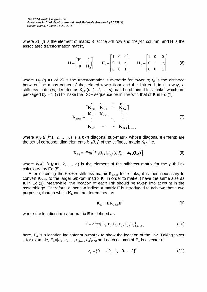
where Hg (g =1 or 2) is the transformation sub-matrix for tower g; rg is the distance between the mass center of the related tower floor and the link end. In this way, nstiffness matrices, denoted as Kl,p (p=1, 2, …, n), can be obtained for n links, which are packaged by Eq. (7) to make the DOF sequence be in line with that of K in Eq.(1)
1 1 2
11 12 16
21 22
61 66 6 6
L L LX Y
L L L
L LLinks
L L n n
1 1 21 1 2L L L1 1 21 1 21 1 21 1 2L L L1 1 21 1 2L L L1 1 2
11 12 16 11 12 1611 12 16L L L11 12 16 11 12 16L L L11 12 16
11 12 16
11 12 1611 12 16L L L11 12 16
11 12 16L L L11 12 16 11 12 16 11 12 16
11 12 16 11 12 1611 12 16L L L11 12 16 11 12 16L L L11 12 16
11 12 16L L L11 12 16 11 12 16L L L11 12 16
61 66 61 6661 66L L61 66 61 66L L61 66
K K KK K
K
K K
(7)
where KLij (i, j=1, 2, …, 6) is a n×n diagonal sub-matrix whose diagonal elements are the set of corresponding elements kl, p(i, j) of the stiffness matrix Kl,p, i.e.
,1 ,2 ,( , ), ( , ), , ( , )Lij l l l ndiag k i j k i j k i j diag k i j k i j k i j diag k i j k i j k i j( , ), ( , ), , ( , )diag k i j k i j k i j( , ), ( , ), , ( , ) ( , ), ( , ), , ( , )diag k i j k i j k i j( , ), ( , ), , ( , )( , ), ( , ), , ( , )diag k i j k i j k i j( , ), ( , ), , ( , ) ( , ), ( , ), , ( , )diag k i j k i j k i j( , ), ( , ), , ( , )( , ), ( , ), , ( , )Lij l l l n( , ), ( , ), , ( , )diag k i j k i j k i j( , ), ( , ), , ( , )Lij l l l n( , ), ( , ), , ( , ) ( , ), ( , ), , ( , )Lij l l l n( , ), ( , ), , ( , )diag k i j k i j k i j( , ), ( , ), , ( , )Lij l l l n( , ), ( , ), , ( , ),1 ,2 ,( , ), ( , ), , ( , ),1 ,2 ,Lij l l l n,1 ,2 ,( , ), ( , ), , ( , ),1 ,2 ,diag k i j k i j k i j,1 ,2 ,( , ), ( , ), , ( , ),1 ,2 ,Lij l l l n,1 ,2 ,( , ), ( , ), , ( , ),1 ,2 , ,1 ,2 ,( , ), ( , ), , ( , ),1 ,2 ,Lij l l l n,1 ,2 ,( , ), ( , ), , ( , ),1 ,2 ,diag k i j k i j k i j,1 ,2 ,( , ), ( , ), , ( , ),1 ,2 ,Lij l l l n,1 ,2 ,( , ), ( , ), , ( , ),1 ,2 ,( , ), ( , ), , ( , )diag k i j k i j k i j( , ), ( , ), , ( , ) ( , ), ( , ), , ( , )diag k i j k i j k i j( , ), ( , ), , ( , ) ( , ), ( , ), , ( , )diag k i j k i j k i j( , ), ( , ), , ( , ) ( , ), ( , ), , ( , )diag k i j k i j k i j( , ), ( , ), , ( , )( , ), ( , ), , ( , )Lij l l l n( , ), ( , ), , ( , )diag k i j k i j k i j( , ), ( , ), , ( , )Lij l l l n( , ), ( , ), , ( , ) ( , ), ( , ), , ( , )Lij l l l n( , ), ( , ), , ( , )diag k i j k i j k i j( , ), ( , ), , ( , )Lij l l l n( , ), ( , ), , ( , ) ( , ), ( , ), , ( , )Lij l l l n( , ), ( , ), , ( , )diag k i j k i j k i j( , ), ( , ), , ( , )Lij l l l n( , ), ( , ), , ( , ) ( , ), ( , ), , ( , )Lij l l l n( , ), ( , ), , ( , )diag k i j k i j k i j( , ), ( , ), , ( , )Lij l l l n( , ), ( , ), , ( , ),1 ,2 ,( , ), ( , ), , ( , ),1 ,2 ,Lij l l l n,1 ,2 ,( , ), ( , ), , ( , ),1 ,2 ,diag k i j k i j k i j,1 ,2 ,( , ), ( , ), , ( , ),1 ,2 ,Lij l l l n,1 ,2 ,( , ), ( , ), , ( , ),1 ,2 , ,1 ,2 ,( , ), ( , ), , ( , ),1 ,2 ,Lij l l l n,1 ,2 ,( , ), ( , ), , ( , ),1 ,2 ,diag k i j k i j k i j,1 ,2 ,( , ), ( , ), , ( , ),1 ,2 ,Lij l l l n,1 ,2 ,( , ), ( , ), , ( , ),1 ,2 , ,1 ,2 ,( , ), ( , ), , ( , ),1 ,2 ,Lij l l l n,1 ,2 ,( , ), ( , ), , ( , ),1 ,2 ,diag k i j k i j k i j,1 ,2 ,( , ), ( , ), , ( , ),1 ,2 ,Lij l l l n,1 ,2 ,( , ), ( , ), , ( , ),1 ,2 , ,1 ,2 ,( , ), ( , ), , ( , ),1 ,2 ,Lij l l l n,1 ,2 ,( , ), ( , ), , ( , ),1 ,2 ,diag k i j k i j k i j,1 ,2 ,( , ), ( , ), , ( , ),1 ,2 ,Lij l l l n,1 ,2 ,( , ), ( , ), , ( , ),1 ,2 ,K (8)
where kl,p(i, j) (p=1, 2, …, n) is the element of the stiffness matrix for the p-th link calculated by Eq.(5).
After obtaining the 6n×6n stiffness matrix KLinks for n links, it is then necessary to convert KLinks to the larger 6m×6m matrix KL in order to make it have the same size as K in Eq.(1). Meanwhile, the location of each link should be taken into account in the assemblage. Therefore, a location indicator matrix E is introduced to achieve these two purposes, though which KL can be determined as
TLinksLK EK E (9)
where the location indicator matrix E is defined as
1 1 1 2 2 2 6 6, , , , ,
m ndiag
E E E E E E E (10)
here, Eg is a location indicator sub-matrix to show the location of the link. Taking tower 1 for example, E1=[e1, e2,…, ep,…, en]m×n and each column of E1 is a vector as
0, 0, 1, 0 0 Tpe 0, 0, 1, 0 0 T (11)
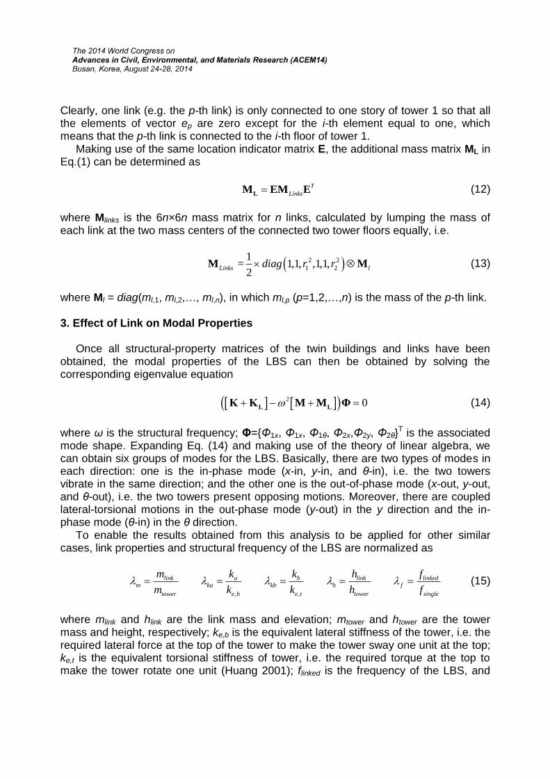
Clearly, one link (e.g. the p-th link) is only connected to one story of tower 1 so that all the elements of vector ep are zero except for the i-th element equal to one, which means that the p-th link is connected to the i-th floor of tower 1.
Making use of the same location indicator matrix E, the additional mass matrix ML in Eq.(1) can be determined as
TLinksLM EM E (12)
where Mlinks is the 6n×6n mass matrix for n links, calculated by lumping the mass of each link at the two mass centers of the connected two tower floors equally, i.e.
2 21 2
1 = 1,1, ,1,1,2Links ldiag r r M M (13)
where Ml = diag(ml,1, ml,2,…, ml,n), in which ml,p (p=1,2,…,n) is the mass of the p-th link.
3. Effect of Link on Modal Properties
Once all structural-property matrices of the twin buildings and links have been obtained, the modal properties of the LBS can then be obtained by solving the corresponding eigenvalue equation
2 0 L LΚ Κ M M Φ (14)
where ω is the structural frequency; Φ={Φ1x, Φ1x, Φ1θ, Φ2x,Φ2y, Φ2θ}T is the associated mode shape. Expanding Eq. (14) and making use of the theory of linear algebra, we can obtain six groups of modes for the LBS. Basically, there are two types of modes in each direction: one is the in-phase mode (x-in, y-in, and θ-in), i.e. the two towers vibrate in the same direction; and the other one is the out-of-phase mode (x-out, y-out, and θ-out), i.e. the two towers present opposing motions. Moreover, there are coupled lateral-torsional motions in the out-phase mode (y-out) in the y direction and the in-phase mode (θ-in) in the θ direction.
To enable the results obtained from this analysis to be applied for other similar cases, link properties and structural frequency of the LBS are normalized as
, ,
link a b link linkedm ka kb h f
tower e b e t tower single
m k k h fm k k h f
(15)
where mlink and hlink are the link mass and elevation; mtower and htower are the tower mass and height, respectively; ke,b is the equivalent lateral stiffness of the tower, i.e. therequired lateral force at the top of the tower to make the tower sway one unit at the top;ke,t is the equivalent torsional stiffness of tower, i.e. the required torque at the top to make the tower rotate one unit (Huang 2001); flinked is the frequency of the LBS, and
0.0010.02
0.040.060.08
0.1
0.20.4
0.60.8
1
0.7
0.8
0.9
1
1.1
mh
frequ
ency
ratio
f
0.020.04
0.060.08
0.1 10-2 10
-1 100 10
1 102 10
30.5
1
1.5
2
2.5
kam
frequ
ency
ratio
f
fsingle is the corresponding frequency of a single isolated tower. 3.1. Modal Properties in the x Direction
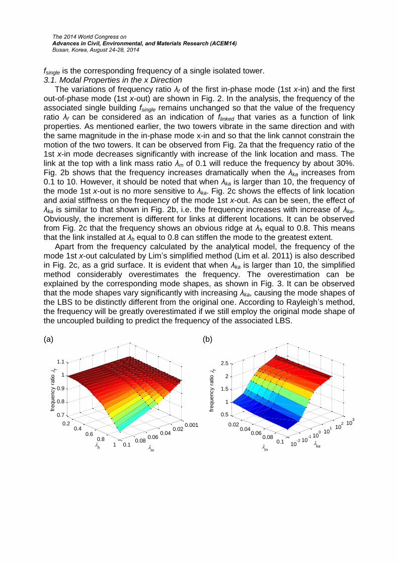
The variations of frequency ratio λf of the first in-phase mode (1st x-in) and the first out-of-phase mode (1st x-out) are shown in Fig. 2. In the analysis, the frequency of the associated single building fsingle remains unchanged so that the value of the frequency ratio λf can be considered as an indication of flinked that varies as a function of link properties. As mentioned earlier, the two towers vibrate in the same direction and with the same magnitude in the in-phase mode x-in and so that the link cannot constrain the motion of the two towers. It can be observed from Fig. 2a that the frequency ratio of the 1st x-in mode decreases significantly with increase of the link location and mass. The link at the top with a link mass ratio λm of 0.1 will reduce the frequency by about 30%. Fig. 2b shows that the frequency increases dramatically when the λka increases from 0.1 to 10. However, it should be noted that when λka is larger than 10, the frequency of the mode 1st x-out is no more sensitive to λka. Fig. 2c shows the effects of link location and axial stiffness on the frequency of the mode 1st x-out. As can be seen, the effect of λka is similar to that shown in Fig. 2b, i.e. the frequency increases with increase of λka.Obviously, the increment is different for links at different locations. It can be observed from Fig. 2c that the frequency shows an obvious ridge at λh equal to 0.8. This means that the link installed at λh equal to 0.8 can stiffen the mode to the greatest extent.
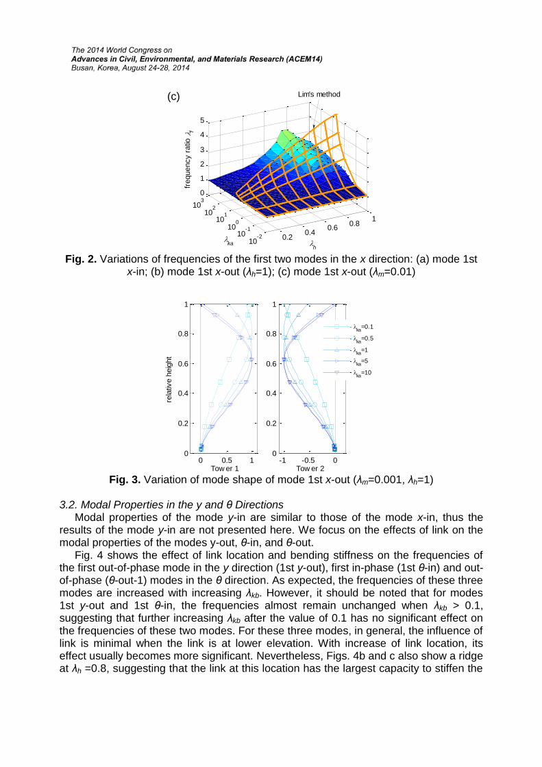
Apart from the frequency calculated by the analytical model, the frequency of the mode 1st x-out calculated by Lim’s simplified method (Lim et al. 2011) is also describedin Fig. 2c, as a grid surface. It is evident that when λka is larger than 10, the simplified method considerably overestimates the frequency. The overestimation can be explained by the corresponding mode shapes, as shown in Fig. 3. It can be observed that the mode shapes vary significantly with increasing λka, causing the mode shapes of the LBS to be distinctly different from the original one. According to Rayleigh’s method, the frequency will be greatly overestimated if we still employ the original mode shape of the uncoupled building to predict the frequency of the associated LBS.
(a) (b)
0.2 0.4 0.6 0.8 1
10-210
-110010
110210
30
1
2
3
4
5
hka
frequ
ency
ratio
f
Lim's method(c)
Fig. 2. Variations of frequencies of the first two modes in the x direction: (a) mode 1stx-in; (b) mode 1st x-out (λh=1); (c) mode 1st x-out (λm=0.01)
0 0.5 10
0.2
0.4
0.6
0.8
1
Tow er 1
rela
tive
heig
ht
-1 -0.5 00
0.2
0.4
0.6
0.8
1
Tow er 2
ka=0.1
ka=0.5
ka=1
ka=5
ka=10
Fig. 3. Variation of mode shape of mode 1st x-out (λm=0.001, λh=1)
3.2. Modal Properties in the y and θ Directions Modal properties of the mode y-in are similar to those of the mode x-in, thus the
results of the mode y-in are not presented here. We focus on the effects of link on the modal properties of the modes y-out, θ-in, and θ-out.
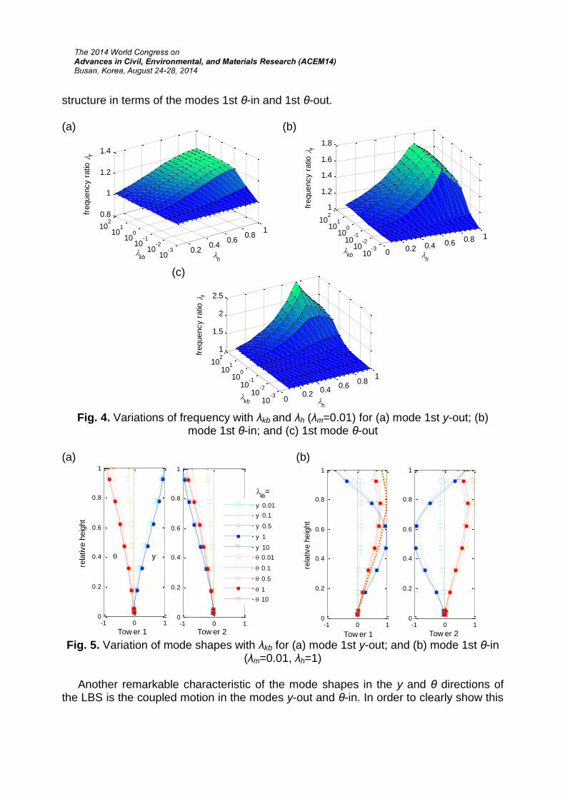
Fig. 4 shows the effect of link location and bending stiffness on the frequencies of the first out-of-phase mode in the y direction (1st y-out), first in-phase (1st θ-in) and out-of-phase (θ-out-1) modes in the θ direction. As expected, the frequencies of these three modes are increased with increasing λkb. However, it should be noted that for modes 1st y-out and 1st θ-in, the frequencies almost remain unchanged when λkb > 0.1, suggesting that further increasing λkb after the value of 0.1 has no significant effect on the frequencies of these two modes. For these three modes, in general, the influence of link is minimal when the link is at lower elevation. With increase of link location, its effect usually becomes more significant. Nevertheless, Figs. 4b and c also show a ridge at λh =0.8, suggesting that the link at this location has the largest capacity to stiffen the
-1 0 10
0.2
0.4
0.6
0.8
1
Tow er 1
rela
tive
heig
ht
y
-1 0 10
0.2
0.4
0.6
0.8
1
Tow er 2
kb=
y 0.01y 0.1
y 0.5
y 1
y 10 0.01
0.1
0.5
1 10
-1 0 10
0.2
0.4
0.6
0.8
1
Tow er 1
rela
tive
heig
ht
-1 0 10
0.2
0.4
0.6
0.8
1
Tow er 2
0 0.2 0.4 0.6 0.8 1
10-310
-210-110
010110
21
1.5
2
2.5
hkb
frequ
ency
ratio
f
0.2 0.4 0.6 0.8 1
10-310
-210-110
010110
20.8
1
1.2
1.4
hkb
frequ
ency
ratio
f
0 0.2 0.4 0.6 0.8 1
10-310
-210-110
010110
21
1.2
1.4
1.6
1.8
hkb
frequ
ency
ratio
f
structure in terms of the modes 1st θ-in and 1st θ-out.
(a) (b)
(c)
Fig. 4. Variations of frequency with λkb and λh (λm=0.01) for (a) mode 1st y-out; (b) mode 1st θ-in; and (c) 1st mode θ-out
(a) (b)
Fig. 5. Variation of mode shapes with λkb for (a) mode 1st y-out; and (b) mode 1st θ-in (λm=0.01, λh=1)
Another remarkable characteristic of the mode shapes in the y and θ directions of the LBS is the coupled motion in the modes y-out and θ-in. In order to clearly show this
coupling effect, the mode shapes of the modes 1st y-out and 1st θ-in are illustrated in Fig. 5 for different values of λkb. It shows that when λkb is larger than 0.1, the coupled components are rather considerable. Therefore, it is speculated that for the LBS, the motion in the y direction could induce noticeable coupled motion in the θ direction and vice versa.
4. Effect of Link on Wind-induced Responses
Before calculating the dynamic responses, a pressure measurement experiment was carried out in the boundary layer wind tunnel at the CLP Power Wind/Wave Tunnel Facility at the Hong Kong University of Science and Technology to obtain wind force information. The effects of link are then quantified by the maximum standard deviation of displacement response by inputting the acquired wind force data. Here we focus on the results for wind direction of 0o, i.e. when the wind flows along y direction. In view of the symmetric arrangement in this direction, only the results of tower 1 are presented.
4.1 Effect of link mass
(a) (b)
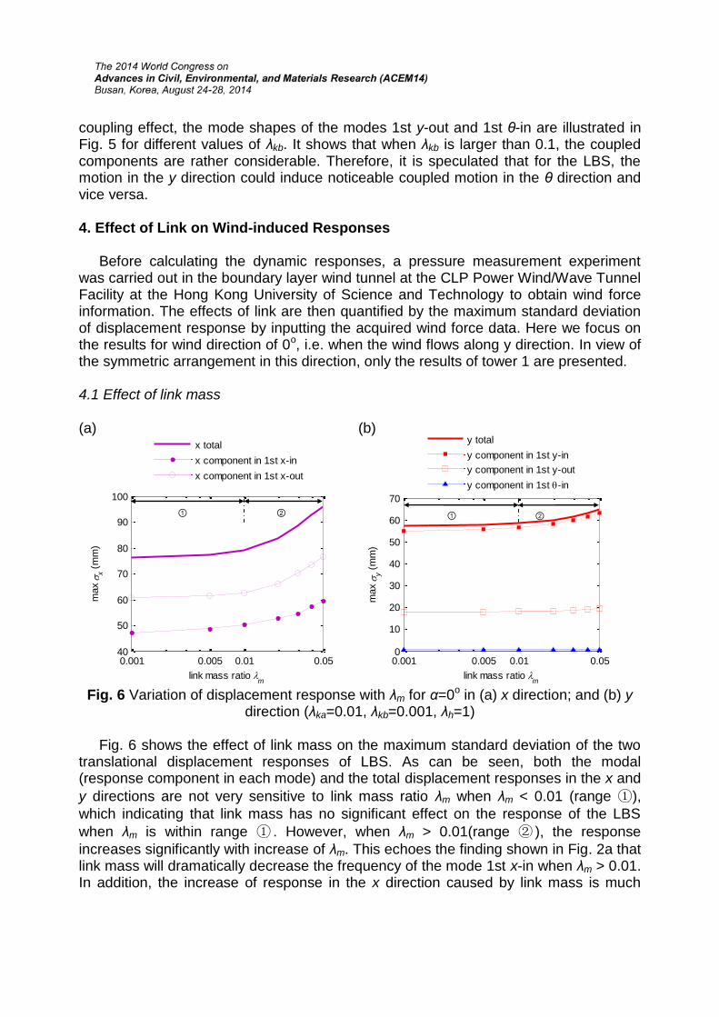
Fig. 6 Variation of displacement response with λm for α=0o in (a) x direction; and (b) ydirection (λka=0.01, λkb=0.001, λh=1)
Fig. 6 shows the effect of link mass on the maximum standard deviation of the two translational displacement responses of LBS. As can be seen, both the modal (response component in each mode) and the total displacement responses in the x and y directions are not very sensitive to link mass ratio λm when λm < 0.01 (range ①), which indicating that link mass has no significant effect on the response of the LBS when λm is within range ① . However, when λm > 0.01(range ② ), the response increases significantly with increase of λm. This echoes the finding shown in Fig. 2a that link mass will dramatically decrease the frequency of the mode 1st x-in when λm > 0.01. In addition, the increase of response in the x direction caused by link mass is much
0.001 0.005 0.01 0.0540
50
60
70
80
90
100
link mass ratio m
max
x (m
m)
x totalx component in 1st x-inx component in 1st x-out
①
②
0.001 0.005 0.01 0.050
10
20
30
40
50
60
70
link mass ratio m
max
y (m
m)
y totaly component in 1st y-iny component in 1st y-outy component in 1st -in
①
②
larger than that in the y direction, since the cross-wind force (x direction) spectrum is steeper than the along-wind force (y direction) spectrum in the range of frequency of most tall buildings.
4.2 Effect of Link Stiffness The effect of axial stiffness of the link on the maximum standard deviation of
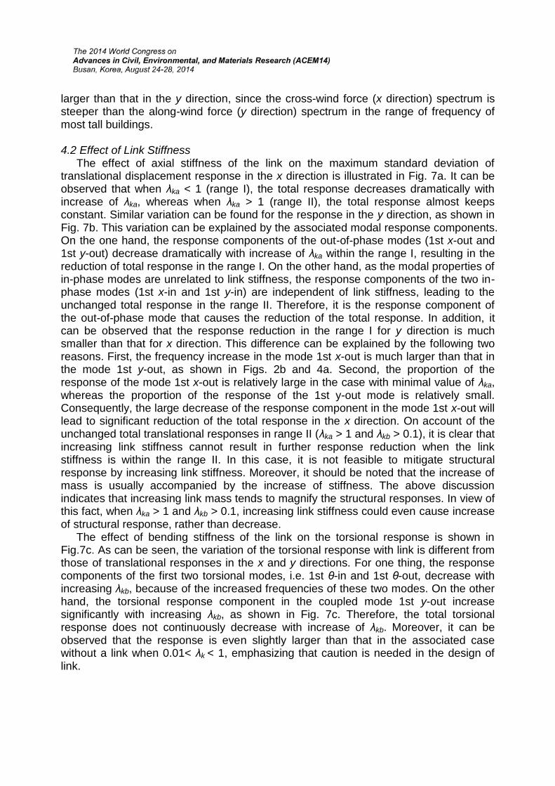
translational displacement response in the x direction is illustrated in Fig. 7a. It can be observed that when λka < 1 (range I), the total response decreases dramatically with increase of λka, whereas when λka > 1 (range II), the total response almost keeps constant. Similar variation can be found for the response in the y direction, as shown in Fig. 7b. This variation can be explained by the associated modal response components. On the one hand, the response components of the out-of-phase modes (1st x-out and 1st y-out) decrease dramatically with increase of λka within the range I, resulting in the reduction of total response in the range I. On the other hand, as the modal properties of in-phase modes are unrelated to link stiffness, the response components of the two in-phase modes (1st x-in and 1st y-in) are independent of link stiffness, leading to the unchanged total response in the range II. Therefore, it is the response component of the out-of-phase mode that causes the reduction of the total response. In addition, it can be observed that the response reduction in the range I for y direction is much smaller than that for x direction. This difference can be explained by the following two reasons. First, the frequency increase in the mode 1st x-out is much larger than that in the mode 1st y-out, as shown in Figs. 2b and 4a. Second, the proportion of the response of the mode 1st x-out is relatively large in the case with minimal value of λka,whereas the proportion of the response of the 1st y-out mode is relatively small. Consequently, the large decrease of the response component in the mode 1st x-out will lead to significant reduction of the total response in the x direction. On account of the unchanged total translational responses in range II (λka > 1 and λkb > 0.1), it is clear that increasing link stiffness cannot result in further response reduction when the link stiffness is within the range II. In this case, it is not feasible to mitigate structural response by increasing link stiffness. Moreover, it should be noted that the increase of mass is usually accompanied by the increase of stiffness. The above discussion indicates that increasing link mass tends to magnify the structural responses. In view of this fact, when λka > 1 and λkb > 0.1, increasing link stiffness could even cause increase of structural response, rather than decrease.
The effect of bending stiffness of the link on the torsional response is shown in Fig.7c. As can be seen, the variation of the torsional response with link is different from those of translational responses in the x and y directions. For one thing, the response components of the first two torsional modes, i.e. 1st θ-in and 1st θ-out, decrease with increasing λkb, because of the increased frequencies of these two modes. On the other hand, the torsional response component in the coupled mode 1st y-out increase significantly with increasing λkb, as shown in Fig. 7c. Therefore, the total torsional response does not continuously decrease with increase of λkb. Moreover, it can be observed that the response is even slightly larger than that in the associated case without a link when 0.01< λk < 1, emphasizing that caution is needed in the design of link.
(a) (b)
(c)
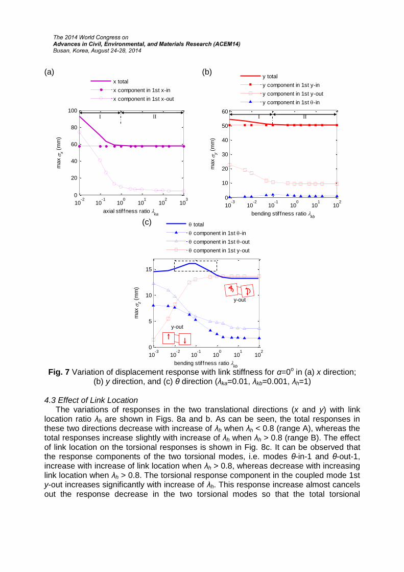
Fig. 7 Variation of displacement response with link stiffness for α=0o in (a) x direction; (b) y direction, and (c) θ direction (λka=0.01, λkb=0.001, λh=1)
4.3 Effect of Link Location The variations of responses in the two translational directions (x and y) with link
location ratio λh are shown in Figs. 8a and b. As can be seen, the total responses in these two directions decrease with increase of λh when λh < 0.8 (range A), whereas the total responses increase slightly with increase of λh when λh > 0.8 (range B). The effect of link location on the torsional responses is shown in Fig. 8c. It can be observed that the response components of the two torsional modes, i.e. modes θ-in-1 and θ-out-1, increase with increase of link location when λh > 0.8, whereas decrease with increasing link location when λh > 0.8. The torsional response component in the coupled mode 1st y-out increases significantly with increase of λh. This response increase almost cancels out the response decrease in the two torsional modes so that the total torsional
10-2
10-1
100
101
102
103
0
20
40
60
80
100
axial stif fness ratio ka
max
x (m
m)
x totalx component in 1st x-inx component in 1st x-out
I II
10-3
10-2
10-1
100
101
102
0
10
20
30
40
50
60
bending stif fness ratio kbm
ax
y (mm
)
y totaly component in 1st y-iny component in 1st y-outy component in 1st -in
I II
10-3
10-2
10-1
100
101
102
0
5
10
15
bending stif fness ratio kb
max
z (m
m)
total component in 1st -in component in 1st -out component in 1st y-out
y-out
y-out
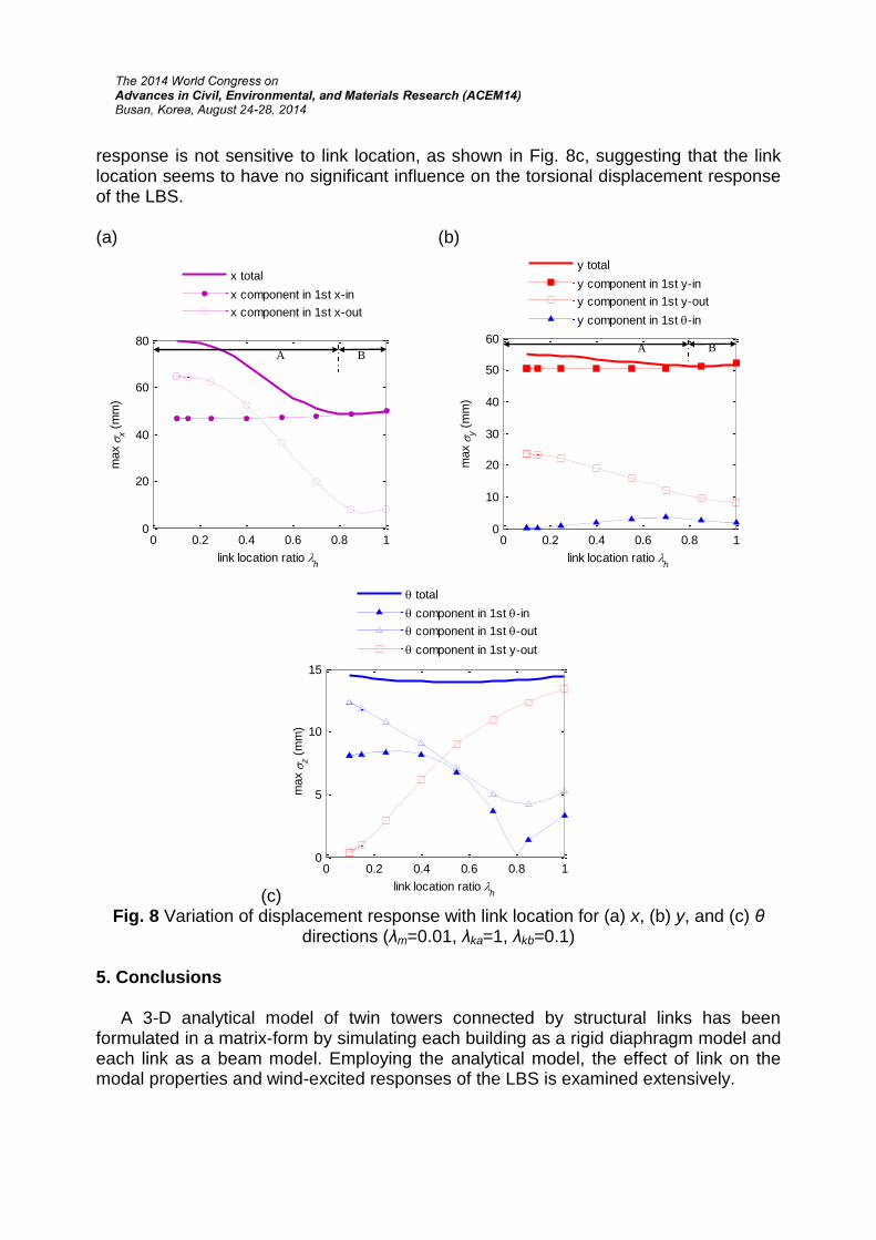
response is not sensitive to link location, as shown in Fig. 8c, suggesting that the link location seems to have no significant influence on the torsional displacement response of the LBS.
(a) (b)
(c)0 0.2 0.4 0.6 0.8 1
0
5
10
15
link location ratio h
max
z (m
m)
total component in 1st -in component in 1st -out component in 1st y-out
Fig. 8 Variation of displacement response with link location for (a) x, (b) y, and (c) θdirections (λm=0.01, λka=1, λkb=0.1)
5. Conclusions
A 3-D analytical model of twin towers connected by structural links has been formulated in a matrix-form by simulating each building as a rigid diaphragm model and each link as a beam model. Employing the analytical model, the effect of link on the modal properties and wind-excited responses of the LBS is examined extensively.
0 0.2 0.4 0.6 0.8 10
20
40
60
80
link location ratio h
max
x (m
m)
x totalx component in 1st x-inx component in 1st x-out
A B
0 0.2 0.4 0.6 0.8 10
10
20
30
40
50
60
link location ratio h
max
y (m
m)
y totaly component in 1st y-iny component in 1st y-outy component in 1st -in
A B
1) Increasing link mass will significantly reduce the frequency of the system when λm > 0.01 and hence will increase structural responses, especially for cross-wind response. The effect of link mass is negligible when λm < 0.01.
2) When λka <1 or λkb <0.1, increasing link stiffness will lead to considerable increase of the frequencies of the two translational out-of-phase modes, and consequently mitigates both responses of these two modes and total responses. However, when λka >1 and λkb >0.1, the frequencies and structural responses are not sensitive to link stiffness. In addition, due to the coupled motion between y and θ directions, the total torsional response is not reduced much with increase of λkb. Compared to the torsional response of two isolated buildings, the response of the LBS is even increased when 0.01< λkb <1.
3) When λh < 0.8, the frequencies of the modes 1st x-out, 1st y-out, 1st θ-in, and 1st θ-out increase with increase of λh, whereas when λh > 0.8, the frequencies of modes 1st x-out, 1st θ-in, and 1st θ-out decreases with increase of λh. Accordingly, the two translational responses in the x and y directions decrease with increase of λh when λh <0.8, whereas increase slightly with increase of λh when λh > 0.8. The total torsional response, however, is not sensitive to link location since the response reduction in the modes 1st θ-in and 1st θ-out is almost canceled out by the increase of torsional component in the mode 1st y-out.
REFERENCES
Clough, R.W. and Penzien, J. (1993), Dynamics of structures, McGraw-Hill New York Huang, K. (2001), Static, seismic and wind-resistant analysis of linked two towers,
Zhejiang University Lee, D.G., Kim, H.S. and Ko, H. (2010), “Evaluation of coupling–control effect of a sky‐
bridge for adjacent tall buildings”, The Structural Design of Tall and Special Buildings. 21(5), 311-328.
Lim, J. (2009), Structural coupling and wind-induced response of twin tall buildings with a skybridge, Colorado State University
Lim, J., Bienkiewicz, B. and Richards, E. (2011), “Modeling of structural coupling for assessment of modal properties of twin tall buildings with a skybridge”, J. Wind Eng. Ind. Aerodyn., 99(5), 615-623.
Przemieniecki, J.S. (1985), Theory of matrix structural analysis, Courier Dover Publications
Wilson, E.L. (2002), Three-dimensional static and dynamic analysis of structures, CSi Computers and Structures, Berkeley
Xie, J. and Irwin, P.A. (2001), “Wind-induced response of a twin-tower structure”, WIND STRUCT INT J. 4(6), 495-504.