ji8 - evols at university of hawaii at manoa: home
TRANSCRIPT
~.
.~
u
HAWAII GEOTHERMAL PROJECTENGINEERING PROGRAM
CONCEPTUAL DESI GN OF A10Mrl -.
REGENERATIVE ISOBUTANEGEOTHE~1AL POWER PLANT
TECHNICAL REPORT No, 18
October 15, 1976
Prepared Under
NATIONAL SCIENCE FOUNDATIONRsearch Grant No. GI-38319
andENERGY RESEARCH AND DEVELOPMENT ADMINISTRATION
Research Grant No. E(04-3)-lO~3
AC0 3-7tPeT2..B30.2
By
Ashok K. Guptaand
James C. S. Chou
Department of Mechanical EngineeringVniversity of Ha~aii
Honol ul u, Hawai i ·96822
'.~
i..~- DISCLAIMER --,
This book was prepared as an account of work sponsored by an agency of the United States Government.Neither the United Stirtes Government nor any agency thereof, nor any 01 their employees, makes anywarranty, express or implied. or assumes any legal liability or responsibility' for the accuracy.completeness. or usefulness of any information, apparatus, product, or process disclosed. orrepresents that its use would not infringe privately owned rights. Reference herein to any specificcommercial product. process, Of service by trade name. trademark. manufacturer. or otherwise, does
not necessarily constitute or imply its endorsement. 'recommendation, or favoring by the United Ji8States Government or any agency thereof. The \News and opinions of authors expressed herein do not . 'necessarily state or reflect those of the United States Government or any agency thereof.
DtmIBUTlOl Of ms DOCuum IS 'IUUmD

LIST OF TABLES
TABLE OF CONTENTS
. . . . . . . . . ii
i
LIST OF ILLUSTRATIONS • . . . . . . . . iii
I
~
CHAPTER I.
CHAPTER II.
CHAPTER III.
.CHAP TER IV.
OPTIMUM PRESSURE AND TEMPERATUREWITH ISOBUTANE AS THE WORKINGFLUID . . • • • . . . • . • . .
COMPARISON OF POl~R PRODUCTIONPROCESSES •• ••• • • • •
REGENERATIVE HEAT EXCHANGER DESIGN
CONCEPTUAL DESIGN OF A REGENERATIVEISOBUTANE SYSTEM • • • • • • • • •
1
24
33
51
. . . . . . . . . . ... . . . . . . . . . .
I
I I
~
~
w....,.
CHAPTER V.
REFERENCES
CONCLUS.IONS . . . . . . . . . 68
73

Capital Cost of the Major Componentsof a 10 MW Regenerative IsobutanePower Plant • • •• • • • • • • •
Table
4-1
4-2
4-3
LIST OF TABLES
Pressures, Temperatures,Entha1pies, Flow Rates of a10 MW Plant • • • • • • • •
Capital Cost of the MajorComponents of a 8.5 MW BasicIsobutane Power Plant • • • • . . . . • •
54
66
67
iifIlIIIIi
LL, 1
L
LLLLL~
~
LL
~.'.
~

lv
Figure
1-1
LIST OF ILLUSTRATIONS
Temperature-Enthalpy Relationshipof Isobutane and Water in HeatExchanger
iii
5
~ 1-2
1-3
1-4
1-5
Effect of System Pressure on Work Output 8
Optimum Pressure of Isobutane forMaximum Power Output 9
Effect of Variation of 6Tmin on OutletTemperatures t t and t.· t 11
w"ou -z."ouPattern of Effect of Minimum TemperatureDifference Between Water and Isobutaneon Costs 14
1-6
1-7
1-8
2-1
2-2
3-1
3-2
3-3
3-4
4-1
Effect of Changing Mass Ratio on OutletTemperatures t t and t. t
. w"ou -z."ouTemperature Distribution of Wet SaturatedSteam and Isobutane in a HeatExchanger
Effect of Temperature Distribution ina Wet-Steam Heat Exchange~ on Costs
Methods of Converting Thermal Energyin Hot Geothermal Fluid into UsefulWork
Effects of Downhole Pump on Work Output
Flow Diagram of a RegenerativeIsobutane System
Temperature-Enthalpy Relationship ofIsobutane in a Regenerative HeatExchanger
Layout of Tubes in Shell
Schematic Diagram of a 4-She1l-Passes,8-Tube-Passes Regenerative HeatExchanger
Flow Diagram of 10 MW RegenerativeIsobutane Power Plant
16
·20
23
25
30
38
39
42
47
53

I
lIa:\-I
...
I
~
L
CHAPTER I
OPTIMUM PRESSURE AND TEMPERATURE WITH ISOBUTANE
AS THE WORKING FLUID
Introduction
Binary fluid system may be used for generating power
from geothermal brines. As the name implies, two fluids
are involved in the power production process--the geothermal
fluid and the working fluid. The advantages of isobutane
as the working fluid in a closed cycle have been discussed
by Anderson (15) and Holt, Hutchinson and Cortez (12). In
a basic isobutane cycle, geothermal fluid from the wells
is used to.vaporize and to superheat isobutane in a heat
exchanger. Isobutane vapor then expands through a turbine
to generate useful power. The exhaust vapor is condensed
and pumped to a heat exchanger to complete a cycle.
To improve the thermal efficiency of the basic cycle,
a regenerative heat exchanger may be used to transfer
the heat from the turbine exhaust to the compressed isobutane
entering the main heat exchanger. T9is result~ in reducing
the size of the condenser, cooling equipment, and the main
heat exchanger. Another effect is the increase of the
temperature of the waste brine so that the waste heat could
be utilized effectively.

2
The objective of this study is to evaluate·the
regenerative binary cycle, as applied to the geothermal
brines· for the generation .of power. The selections of the
cycle temperature anq pressure of isobutane have been
. studied since they have great effects on the performance
of a basic or regenerative plant. The results of the study
are reported in this chapter.
The entire system of a binary fluid plant is difficult
to optimize because of its complexity. In such a case, we
may try to optimize the subsystems and then choose a~
optimum combination of these subsystems. The most critical
subsystem is the main heat exch~nger. The type of flow and
the temperature distribution of fluids in the heat exchanger
affect the 'size of the heat exchanger and the power output
of the system, which can be evidenced by heat balance.
The inlet temperature of the hot geothermal fluid
depends upon the reservior temperature and the method of
bringing the fluid to the surface. In a liquid dominated
field, the geothermal fluid may be delivered from a well by
flashing or by pumping. If the fluid is allowed to flow
through the well by'natural forces, a part of the liquid
will become vapor, as the pressure drops when the. fluid
moves up. In this case, the main heat exchanger may be
divided into two sections. In the first section, isobutane
is heated by condensing the flashed brine of the hot
geothermal fluid, and the heat is transferred from hot
Lf )IlI.i
I .
L
I '..
Lf t
L
11..
L,I'-'
L

I i3
liquid brine to isobutane in the second section. If a
suitable pump can be developed to force the fluid out
through the well, the fluid can remain compressed without
flashing, and there is no need for the condensing section
of the heat exchanger. Two cases are considered separately
in determining the optimum temperatures.
Temperature Distribution in Counterflow Heat Exchangerfor the Compressed Geothermal Liquid
While the types of commercial heat exchangers may be
a combination of counterflow, parallel flow, and cross-
flow, pure counterflow heat exchangers are proposed for
extracting 'energy from geothermal fluids since the
temperature distribution of a counterflow arrangement gives
the highest final temperature which isobutane can attain
when it is heated by the hot fluid. An additional advantage
of the counterflow arrangement is that less heating surface•
is required by this arrangement than by parallel flow and
crossflowarrangements (11) •.
There are two- difficulties in heat transfer-problems
involving superheated isobutane. One is the lack. of precise
data on its thermodynamic properties; another is the
peculiarity of the specific heat of superheated isobutane
vapor. To facilitate the interpolation and to increase the(..".I~ precision of the calculations, the temperature-enthalpy
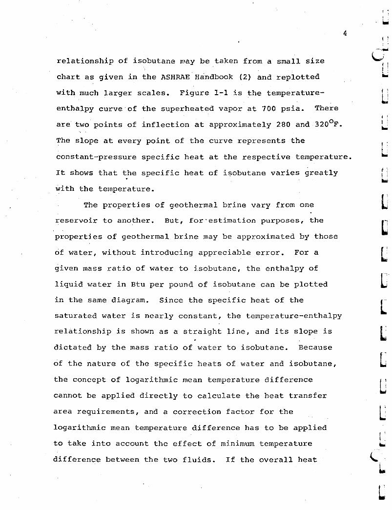
4
relationship of isobutane may be taken from a small size
chart as given in the ASHRAE Handbook (2) and replotted
with much larger scales. Figure 1-1 is the temperature
enthalpy curve of the superheated vapor at 700 psia. There
are two points of inflection at approximately 280 and 320oF..... '
The slope at every point of the curve represents the
constant-pressure specific heat at the respective temperature.
It shows that the specific heat of isobutane varies greatly
with the temperature.
The properties of geothermal brine vary from one
reservoir to another. But, for'estimation purposes, the
properties of geothermal brine may be approximated by those
of water, without introducing appreciable error. For a
given mass ratio of water to isobutane, the enthalpy of
liquid water in Btu per pound of isobutane can be plotted
in the same diagram. Since the specific heat of the
saturated water is nearly constant, the temperature-enthalpy
relationship is shown as a straight line, and its slope is
dictated by the mass ratio of water to isobutane. Because
of the nature of the specific heats of water and isobutane,
the concept of logarithmic mean temperature difference
cannot be applied directly to calculate the heat transfer
area requirements, and a correction factor for the
logarithmic mean temperature difference has to be applied
to take into account the effect of minimum temperature
difference between the two fluids. If the overall heat
I I
[
(;-I 1
LJf 1
L1tIiIl.I
I...
LI'iI./
\.L.
L

5
ISOBUTANE
",,540~S80~620...660
CONDENSER
MAIN HEATEXCHANGER
",,700
t .lV,>'l,n
WATER
,:",,740
400
t. t'l,,>ou
360
320
280
200
160
120....780
rx..o
I~
~
LU
U
ENTHALPY, BTU/LB ISOBUTANE
Figure 1T"1. Ternperature~Enthalpy Relationship of Isobutaneand Water in Heat Exchanger

6
transfer coefficient U is considered to be fairly constant,o
a numerical step-by-step integration may be used to
determine the required heat transfer area A, ft 2 , per pound
of isobutane,
A = ..L. L AhU ATo
where Ah is th~ enthalpy change per pound of isobutane in
Btu/lb. and AT is the mean temperature difference between
the two fluids in the corresponding interval in of.
In the analysis of an isobutane cycle, the temperature
t.. (Figure 1-1) of the entering isobutane is directly'l-~'l-n
related to the condensing temperature of the cycle and the
outlet pressure of isobutane from the pump. The inlet
temperature t . of the hot geothermal fluid depends uponW~'l-n
the reservoir temperature and the method of bringing the
geothermal fluid to the surface. With the two inlet
temperatures, t.. and t ., fixed as shown in the'l-.)'l-n W,,'l-.n
Figure 1-1, different patterns of temperature distribution
may be obtained by varying the minimum temperature
difference between the two fluids and the slope of the
temperature-enthalpy line for water. The mass ratio of the
two fluids prescribes the slope of the temperature-enthalpy
line for water.
t 1
j....I 1
t..L
f
L
L.;
LI'..
~~
L.,~
I...

~ !
~\-I~
Effects of System Pressure on PoWer Production
The isobutane pressure of the, binary system affects
the power output greatly. The optimum isobutane press~res
were found by trial heat balances. The effects of changing
the isobutane pressure on the work output are shown in
Figure 1-2, based on the following assumptions:
7
u 'Geothermal fluid.Condensing temperature
Pump efficiency
Isobutane turbine efficiency
Temperature difference
4000 F satu~ated water
1200 F
80%
85%'
100F
itI'
~
uuu~
L~
,..,)
~
U
and the optimum isobutane pressure is 1,000 psia for an
outlet temperature di~ference of 10oF.
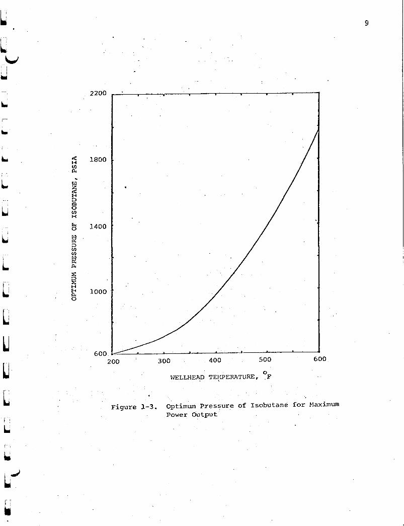
For a given outlet temperature'difference, bTl' and
a minimum temperature difference, there is an optimum
pressure. Many heat balances were made to determine the
opt~mum pressure as a function of water temperature at
wellhead, and the results are-given in Figure ~-3 for an
outlet temperaturerdifference oflOoF. For all the
calculations in this study, a condensing temperature of
120oF, a·pump efficiency of 80%, and an isobutane turbine
efficiency of 85% are assumed. The work output in this
chapter refers to the turbine work minus the work of feed
pump, not including the work of downhole pump and other
auxiliaries.

IIi.J
8
I
LCONDENSER
t. ."l,,,'l-n
MAIN HEATEXCHANGER
WATER
t."l,~out
ISOBu'rANE
L
IL
L
I'L.
300 psia
40 .
------------
.........-..-..-..-.. --... .. --
.. -- .. -- .. - .. _ .. -
10
.._ --:.-:- :::-~-:::.. -" _.. _. - .. - .. - ......--. - - -_.
-------1000 psia_._._._.1500 psia
700 psia
- -:'--2000 psia_"_ •• _00 300 psia
o
50
60
40
45
35
30
25
20
Figure 1-2. Effect of Syst&~ Pressure on Work Output
2200
9
1800
1400
1000 .
600200 300 400 500 600
\'i'ELLHEAD TEJ:~ERATURE, of
Figure 1-3. optimum Pressure of Isobutane for MaximumPower Output

Optimum Minimum Temperature Difference in the HeatExchanger for Compressed. Geotherrnal Liquid
The minimum temperature dif.ference in the heat
exchanger plays an important role. As this temperature
'differ~nce'increases, the size and the cost of the heat
10
flow rate ratio of water and isobutane, is shown in
decrease of the outlet temperature of isobutane and the
Figure 1-4, in which a mass ratio of 1.0 is assumed. For
I '
LI 'iIIIJ
LL~
U
[
LLL
4000 F Saturated water
1000 psia
1.0
Overall heat transfercoefficient
Geothermal fluid
Isobutane pressure
Mass ratio of fluidto isobutane
per pound of' the geothermal fluid decreases because of the
exchanger decreases. At the same time, the work output
high heat content of the waste brine. The effect of
changing the minimum temperature difference, 6T • , on them'l-n
outlet temperature of isobutane and water, for a fixed mass
the fixed inlet temperatures, t . . and t ., the outlet. 'l-~'l-n ~~'l-n
temperatures, t. t and t t' vary significantly. The'l-~OU ~~ou
areas of heating surface were calcuiated by numerical
step-by-step integration with the following assumptions:

.--__~-~----c:-JSOBUThNE
11
CONDENSER
'lLJRBINE
t. .1.~'2,n
tlU~OUt
HAIN HEATEXCHANGER
t'i'ATER
r'L-V
~.
f...
.. '
-540-580~620-660-700-740
360
320
200
160
120 1.--_-i._---''-_..L.-_--i.__.L--_-L --a.__.L-._-'--~--.L---J
-780
l>' 280
LL
ENTHALPY, BTU/LB ISOB.U'rANE
~
f.,)
~
Figure l-4, Eff~ct of Variation of 6T. on ~~tlet Temperaturet
ml,nlU.. out and ti.. out'
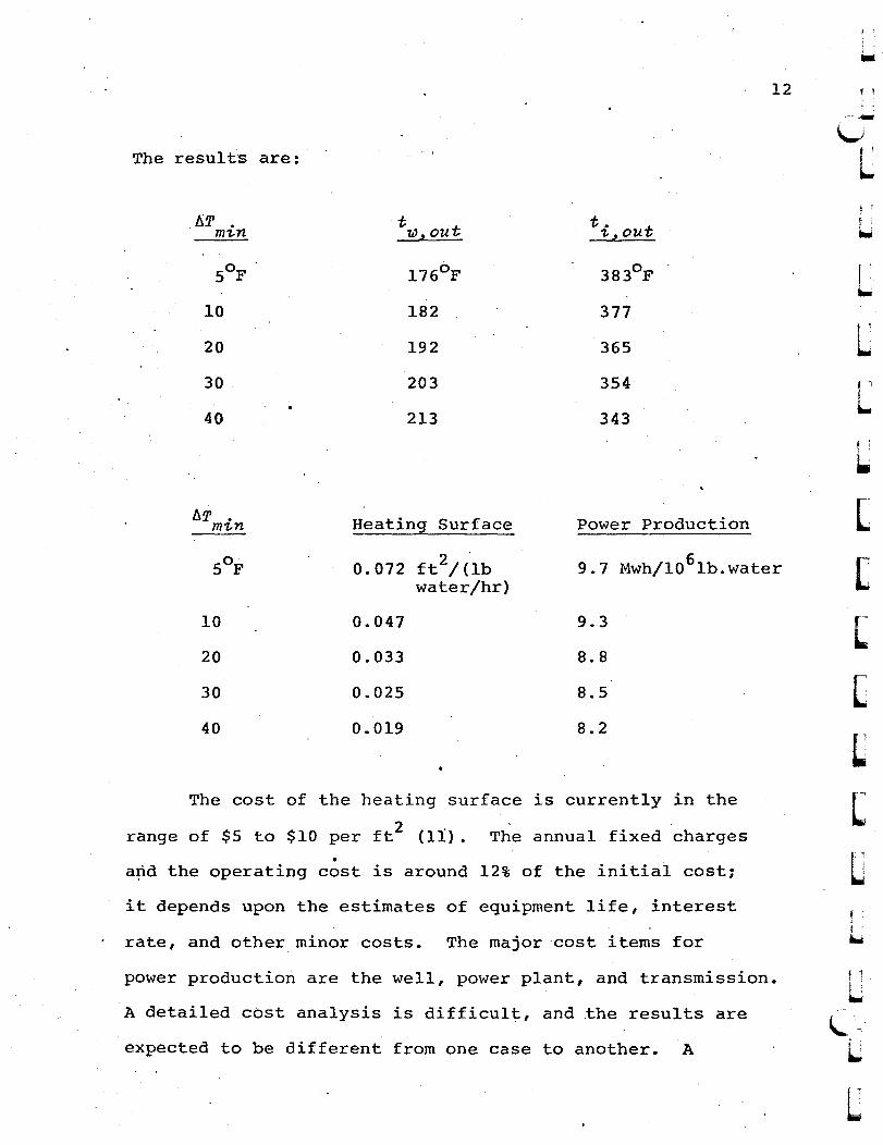
The results are:
~Tmin t t. tlU"oUt 1-"OU
5°F l760 F 383°F
10 182 377
20 192 365
30 203 354
40 213 343
12 I;
I '
L
I....
LL
6Tmin Heating Surface Power Production
5°F 0.072 ft 2/ ("lb 9.7 Mwh/l0 6 lb.waterwater/hr)
10 0.047 9.3
20 0.033 8.8
30 0.025 8.5
40 0.019 8.2
The cost of the heating surface is currently in the
range of $5 to $10 per ft2 (11). The annual fixed charges•
a~d the operating cost is around 12% of the initial cost;
it depends upon the estimates of equipment life, interest
rate, and other minor costs. The major cost items for
power production are the well, power plant, and transmission.
A detailed cost analysis is difficult, and the results are
expected to be different from one case to another. A
L[
[
L(
LLLf 1
L

w~
conservative estimate of the cost of power produced due to
the efficient use of a heat exchanger is 1¢ per Kwh. By
taking 400 F minimum temperature difference as the reference
point, the revenue from the additional power production and
the annual cost of the heat exchanger were compared, as
shown in Figure 1-5. It is interesting to note that based
·on these preliminary cost estimates, the optimum point of
the minimum temperature difference is around 50 F. At a
higher estimate of the revenue or a lower estimate of the
heat exchanger cost, the optimum value of the minimum
temperature difference will be lower. Because of the
13
L~
~~!~
Uf~
~
. .severe scaling on the heating ~urface of the heat exchanger,
caused by the geothermal fluid, a conservative value of the
heat transfer coefficient was used for the heating surface
calculations. A c va1ue of U which is higher than 175 Btu/o(hr) (ft2 ) (oF) will lower the optimum value of the minimum
temperature· difference.
Calculations for 6000 F saturated water at the inlet
of heat exchanger were also performed. As the temperature
of isobutane increases, the optimum pressure of the Rankine
cycle also increases. For 600°F saturated water, the
optimum pressure .0£ isobutane is about 2,000 psia
(Figure 1-3). With all other assumptions to be the same
as the previous case, the optimum value of minimum
temperature difference is again in the neighborhood of 5
to 100 F.
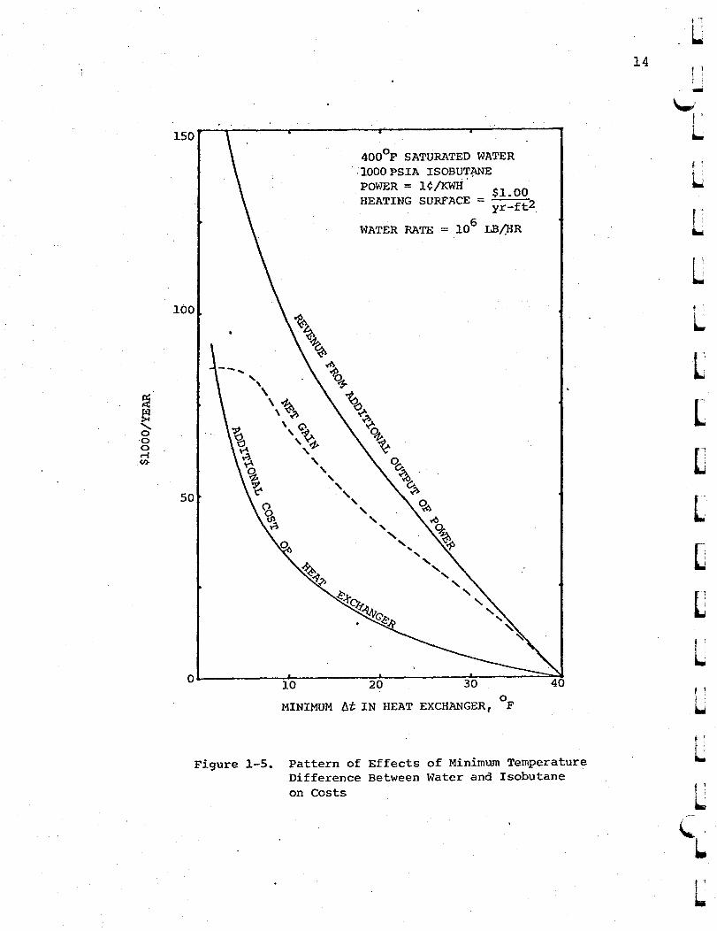
150
400°F SATURATED WATER. :1000 PSIA ISOBUT~
POWER = 1¢!KWH' 0HEATING SURFACE = ~~~~t2
WATER RATE = 106 LB/HR
Figure 1-5. Pattern of Effects of Minimum TemperatureDifference Between Water and Isobutaneon Costs
14
L
f'i...r...
Lf
L
L[
L[
[
~
f 1
L
L
L

~
wvLLLL[
LLL[J
D
U
UL
.(j
L1..1~
Effects of Varying Mass Ra·tio.of Water Flow toIsobutane Flow ror Compressed Geothermal Fluid
The variation of mass flow rate ratios of water to
isobutane, for a fixed minimum temperaturediffe~ence, also,
-affects the heating surface area requirements and the power
output. Having decided that the minimum tempera~ure
oqifferencein the heat exchanger be kept at 5 to 10 F, the
effects of varying mass ratio were evaluated. Tpe location. .
of the minimum temperature difference (Figure I-I} varies,
with the mass ratio. At a given value of minimum
temperature difference, its location moves downwc;lrds as the
slope of the temperature-enthalpy line of water increases.
At a small ratio of water mass to .isobutane mass, the
minimum temperature difference could occur 'at the exit of
water. The advant~ge of lQweri~g the exit temperature o~
water is to lower the amount of waste enetgYi. however, the
cycle efficiency drops as the exit temperature is pushed
down by tilting the enthalpy line of water, This effect
can be seen in Figure 1-6, where the minimum temperature
difference is kept to be 10op~ and the ratio of mass flow
rates is changed by.changing the slope of temperature
enthalpy line of water... With the same assumptions used for
determining the optimum value of. minimum t~mperature
difference for 4000 P saturated water, the required area of
heating surface and the power output were determined for
lOoF minimum temperature difference at various mass ratios.
15
I
. i

I ,[ .
'-
L
L
LLU[
lJ[
U
WI1
n:.... :
f 1
---.-\-"
L
16
-540
CONDENSER
-580-620
in
tlJ).t out
...660-700
ISOBUTANE
MAIN HEATEXCHANGER
-740
t. '1-~Ou
t .w"t.n
WATER
ENTHALPY, BTO/LB ISOBUTANE
360
320
200
160
120L---J.-~_~__&-.._"""-_--A._--Ir..-_......._...&-._--&__.&.-_~_-..a
-780
o~
.. 280
~
~riI~ 240
~
Figure 1-6. Effect of Chang~ng Mass Ratio on OutletTemperatures t and t. t-
lJ).t0ut t."ou
t ' ,
LL
l.
L

~
wv
I '..
L
17
The effect of mass ratio on power output and heating surface
area requirements is as follows:II!I
Mass Ratio ExitHeating Surface" Power Output ~
1b.H2O/lb Temperature " I0 2 Mwh/1061b.waterIsobutane of Water, F ft /(lb.Water/hr)
0.70 142 0.0970 10.7
0.75 147 0.0963 10.9
0.80 155 0.0955 10.8
0.85 165 0.0953 10.6
0.90 172 0.0952 ],0.3
1.00 179 0.0940 9.3
The optimum mass ratio is 0.74 pound of water per
pound of isobutane. The effect of mass ratio on the revenue
from power output is quite significant, but the variation
of cost of heating surface area with mass ratio is not very
A similar evaluation was made for the case of'600oF
saturated water with the following assumed data:
LGeothermal fluid
IsobuLane pressure
Overall heat transfercoefficient
Minimum temperaturedifference
oSaturated 600 F water
2,000 psia
175 Btu/(hr) (ft2 ) (oF)

The re"sults are:
Mass Ratio ExitHeating Surface Power Output
1b.H2O/lb. TemperatureIsobutane of Water,oF ft2/(lb.water/hr) MWh/~061b.water
0.56 145 0.1236 26.28
0.60 155 0.1086 25.78
0,65 ~65 0.1292 24.96
0.70 178 0.~39Q 24 •.10
0,75 ~97 0.14~Q 23,50
where the mass ratio of 0.56 gives the h~ghest power output,
The variation of heating surface area with mass ratio is
different in this case as' compared to one with 400oF. The
heating surface area decreases and then increases with. the
change of the slope of the temperature~enthalpy line for
water. This variation is attributed to the change of the
m~an temperature difference due to flatter temperature-
enthalpy curve for isobutane' at 2,000 psia as compared to
one at 700 psia. In spite of this variation, the effect of
changing the mass ratio on the cost of heating surface area
requirements is not significant, However, the effect of
the variation of mass ratio on the revenue from power output
is very appreciable. No definite relationship between the
geothermal fluid temperature, mass ratio, water exit
temperature, and power output can be suggested, although it
18·
.-"-,,U
LLU
LL[
[
CC[
LLf '
L
L\".,
i.
L
WI
LVu
u
lJ
U
L~.-I
is clear that the exit temperature of the waste water
increases and the power output decreases as the mass ratio
increases.
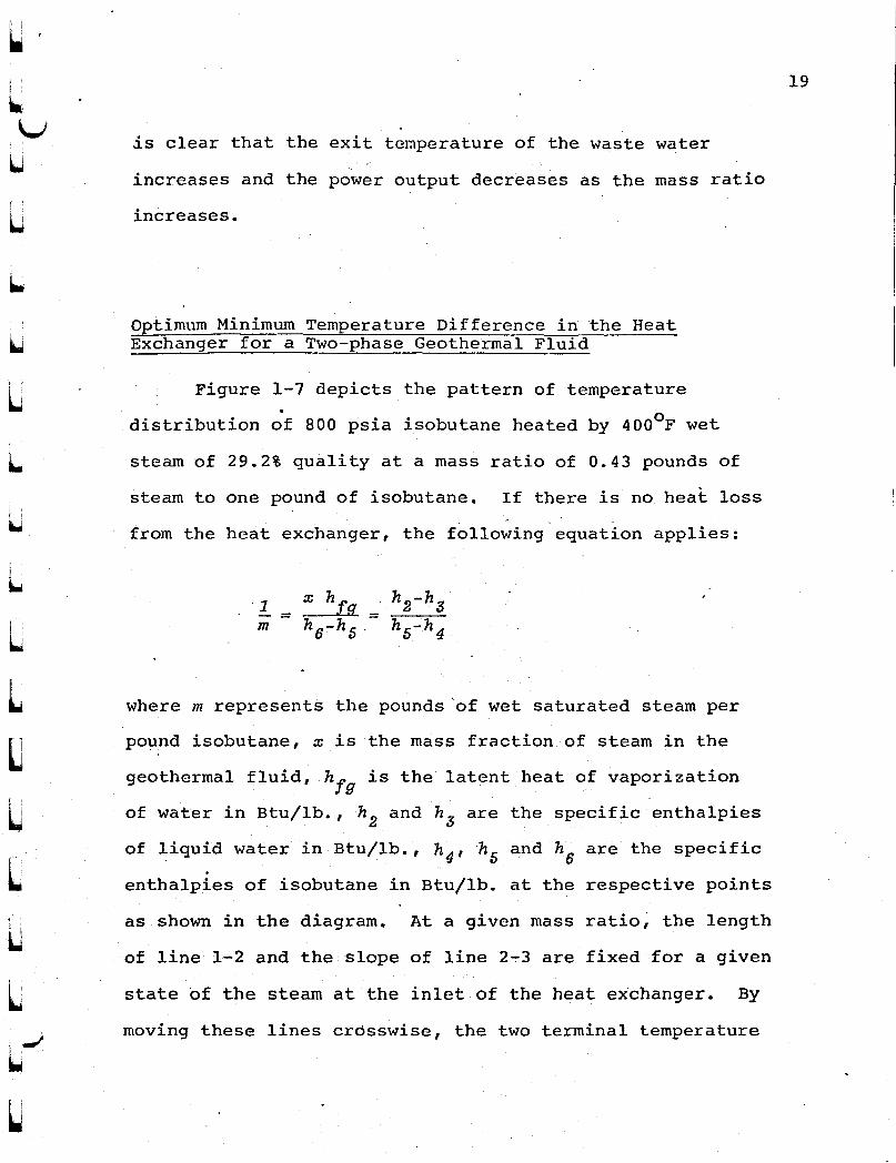
Optimum Minimum Temperature Difference in the HeatExchanger for a Two-phase Geothermal Fluid
Figure 1-7 depicts the pattern of temperature.distribution of 800 psia isobutane heated by 4000 F wet
steam of 29.2% quality at a mass ratio of 0.43 pounds of
steam to one pound of isobutane. If there is no heat loss. - .
from the heat exchanger, the following equation applies:
m
where m represents the pounds'of wet saturated steam per
po~nd isobutane, x is the mass fraction of steam in the
geothermal fluid, h fg is the latent heat of vaporization
of water in Btu/lb., h 2 and hs are the specific entha1pies
of liquid water in Btu/lb., h4,h5 and h6 are the specific
entha1pies of isobutane in Btu/lb. at the respective points
as shown in the diagram. At a given mass ratio, the length
of line 1-2 and the slope of line 2-3 are fixed for a given
state of the steam at the inlet of the heat ex·changer. By
moving these lines crosswise, the two terminal temperature
19

6
l---~
WATERMAIN HEATEXCHANGER 2 5
ISOBUTANE
TURBINE
CONDENSER
PUMP
20
Uf :--\.../
LU
440 r-----r.----...------.---~--_y_--__r--_ !1...
LL
L~
L~
LCLLL
\.,L.
-560-640
(4000F, 29.2% 1
2 Quali ty) ---
l\T21
-720
ENTHALPY, BTU/La ISOBUTANE
Temperature Distribution of Wet SaturatedStearn and Isobutane in a Heat Exchanger
•
Figure 1-7.
360
280
200
1201----~--....-I'----~--~---~--~----J
-800
r...o
~ ,
~vu'
21
differences, 6T1 and 6T2
, increase or decrease simultaneously.
As the mass ratio changes, both the length of line 1-2 and
the slope of line 2-3 are subject to change so that one of
these two terminal temperature differences may remain in the
same degrees. Various combinations of 6T1
and bT2
can be
obtained by changing the mass ratio and by movi~g the point
1 at a given temperature level.I
~ Efforts ~ere made to determine the optimum temperature
differences for the plant which uses geothermal fluid in
the form of liq\1id-vapor mixtures. Prom the point of high
power output, the temperature<of the fluid leaving the plant
should be low, and the thermal efficiency of the cycle
should be high. At a given pressure of isobutane for
required for transferring the heat from the wet steam at a
because of the relatively small size of the heat exchanger
large temperature difference. As an example, calculations
were performed for the following conditions:
800 psia
4000 p wet stearn, 29.2%quality
500 Btu/(hr) (f~2) (oP)175 Btu/(hr) (ft2) (oP)
$1.00/ft2
l¢/Kwh
Geothermal fluid.Isobutane pressure
Heat transfer coefficient,condensing sectionliquid-to-liquidsection
Annual cost of heatingsurface
Power cost
maximum efficiency, effects of temperature distributi~n on
the cost of the heat exchanger were found to be 'insignificant. '
L
LUUU
U

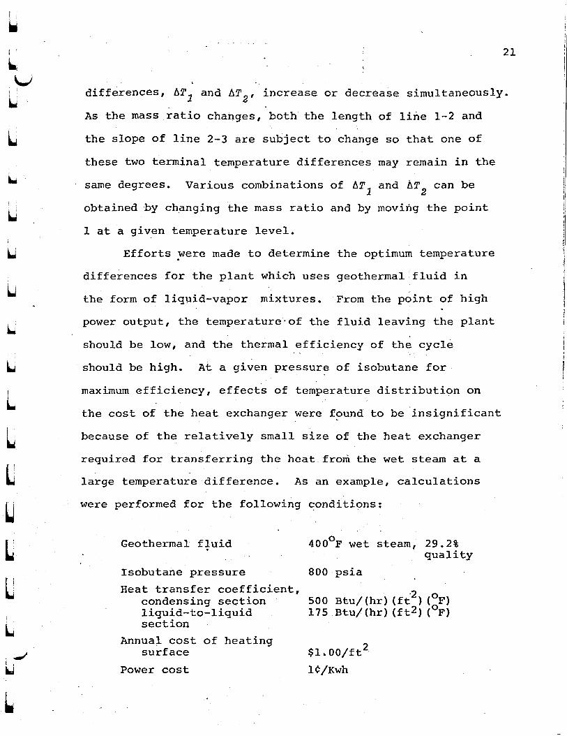
Tne trends of annual gross revenue from power and the
annual cost of heating surface are shown in Figure 1-8.
The optimum combination of the two temperature differences
is around ~Tl=lOoF at the water exit and ~T2=20oF at the
water inlet when the mass ratio of water to isobutane is
. 60.43. In another example, for wet stearn at 312 F, 10.3%
quality and isobutane at 700 psia, the maximum power occurs
at ~Tl=lOoF, ~i2=18oF, with mass ratio = 0.48. From the
above observations, it may be inferred that approximately
~Tl=lOoF and ~T2=20oF are the optimum temperature
differences in general. However, additional heat balances
are recommended for every special conditions.
22f '!--uL
LLLl~
~
~.
~
~
~
LLL
~~
L
U'lvL 2.Or-~--,.---~---.----.,----r---r----..--~---,---'"
23
....
--- --- ---6T~3jj07?
1
GROSS
•
------- .....-- ..-.. _-
1.9
2)4......"'" 0.2
~oo
uL
60504030
COST Op ...HEAT EXCHANGER
20
b;l""=SiiC2.r'- - ------ --- --- --_._- - --- - ---- - - --
o ..~__"'-__"'--__'-_---JL-_---J'---_---'~_---.__-..L__--'-__~
10
0.1
u TEr'~PERATURE DIFFERENCE bT2' of
uL~
Figure l-8. Effects of Temperature Distribution in aWet~Steam Heat Exchanger on Costs

CHAPTER II
COMPARISON OF POWER PRODUCTION PROCESSES
Introduction
The prevailing method of converting energy in the. .
geothermal fluid into power is the two-stage vapor-flashing
method, as illustrated in Figure 2-lA. This type of plant
first became operational in New Zealand and then in several
other countries. In the vapor-flashi~g process, steam is
produced from the geothermal fluid by reducing the pressure
of the fluid to a point below its vapor pressure, Steam
flashed out is used directly to' power a turbine which drives
an electric generator. The design and performance of these
plants have. been reported in many publications and
summarized by Chou and Ahluwalia (7). There are two other
methods under serious study: the binary-fluid method with
isobutane as the. working fluid, and the total-flow-concept
method.
The binary-fluid method has been discussed in
Chapter I. A problem, which has yet to be resolved, is
~he scaling on the water side of the heating surface. To
utilize the heat in the exhaust vapor from the isobutane
turbine, the addition of a regenerative' heat exchanger to
the basic isobutane cycle was suggested. The consequence
is that the exit temperature of fluid in the main heat
I '
l.t 1
W
LLL[
LC[
~
CLlL
~L.
L

25
Cooli.ng..............J--l'iater
Flashed Brine
Steam
Flashi.ngTank
~ ~ .......c::-
GeothermaFluid
(Al TWO-STAGE VAPOR-FLASHING SYSTEM
GeothermalFluid
I~obutane
RegenerativHeat
Exchanger
Condenser
Pump Pump
(Bl REGENERATIVE BINARY SYSTEM
CondenserHelical
ScrewExpander
GeothermalFluid
ImpulseTurbine
Nozzle
GeothermalFluid
L
(C) TOTAL FLOW SYSTEM
lw~
'-
Figure 2-1. Methods of Converting Thermal Energy in HotGeothermal Fluid into Useful Work

26
exchanger ca~,be increased to.such an extent that the waste
heat in the effluent may be used for industrial heating as
described by Chou, et al. (8). Figure 2-IB shows another
version of a regenerativ~ binary system. Here the
regenerative heat exchanger is used to heat and to evaporate
the isobutane flowing in a separate basic cycle. Then the
·hot isobutane vapor is expanded in the second turbine to
produce additional power.
Figure 2-ICshows another method of power production
from geothermal' fluid, studied and advanced by Austin, et al.
at the Lawrence Livermore Laboratory (3). The thermal
energy of the geothermal fluid .is converted to kinetic
energy by the expansion of the fluid through a converging
diverging nozzle, and then the kinetic energy is transformed
into power in an impluse turbine; or the fluid is directly
expanded in some suitable machine such as a helical rotary
screw expander (Figure 2-lC). The basic advantage of this
method is its simplicity. The degree of success of the
total flow concept depends upon the development of a
reliable machine with suffic~ently high thermal efficiency.
A comparison of the power productions of the three processes,
with and without a downhole pump, was made for prQviding
some information on the selection of the processes, as
given in the subsequent section.
!..- ....
\.,1
LLLLLLLLLLLl"r c
~
I .
L
L\.
L.
L

fl;U
U
27
Effects of Downhole Pump on Power Production
In a liquid-dominated reservoir, the hot geothermal
fluid is in a compressed liquid state~ If the hot fluid
is driven out by natural forces through a well, the vapor
pressure of the fluid drops due to the wall friction and
the change of potential energy; thus the vapor flashes out
while the temperature decreases. As a result of this
transition, tne available energy of the fluid decreases as
it moves up. Both the flow rate and the change of available
energy per .unit mass of the geothermal fluid are functions
of vapor pressure drop~ To maximize the power production,
the optimum value of vapor pressure at the wellhead must be
determined in the early st~ges of plant des~gn. For plants
currently in operation, wellhead pressures are in the range
of 50 to 100 psia (13), pumpi!1g hot geothermal fluid from
a reservoir increases the production rate of a well,
eliminates scale formation on the well surface, lessens the
surface fouling in the heat exchangers of a binary cycle
plant, and preserves the available energy of the geothermal
fluid. Several projects to develop downhole pumps are in
progress under the sponsorship of the government. Altho~gh
the future use of pumps depends upon the development of
reliable pumps which are capable of handling hot. geothermal
fluids and the favorable economic analysis of a specific
project, the effects of pumping on power production per unit

28
mass of ·fluid can be estimated within a small uncertainty.
In an actual situation, the enthalpy of the fluid in
a reservoir is different from that at the wellhead due to
the change of potential ene~gy, the pump work, if any, and
the heat loss from the well to its surroundings, However,
by examining the magnitude of each term in energy equation
for a typical well, one may accept the assumption that the
enthalpy of th~ fluid is approximately constant throughout
the well. For example, if the depth of the well is 1,000 ft.,
the change of potential ene~gy is 1.28 Btu/lb. of ge~thermal
fluid. After the well is in operation for a le~gth of time,
the heat transfer to the surroundings may be assumed to be
negligible. The shaft work is about 2~5 Btu/lb. of
geothermal "fluid, and the cha~ge of kinetic energy is also
insignificant. Comparing these to the total enthalpies
in the range of 375 to 625 Btu/lb., it is reasonable to
assume that the enthalpy in a well remains constant. For
simplicity, this assumption is used for the comparisons of
power production per unit mass of. geothermal fluid with or
without a downhole pump in the.well. Other general
assumptions on the fluids are that the thermodynamic
properties of geothermal fluid may be approximated by those
of water, and that the pressure effects on the properties
of liquid may be neglected.
Based on a paper by Anderson CIS), the turbine
efficiencies of isobutane turbines are expected to be higher
LLLL
~
LLLL[
LL~ ~
L~.
L
L

l I.-:U
l..
~ "1
U
LUt.tiLI"
U,
Ui ...1U
~
29
than those of steam turbine of the same ratings. For the
analyses of system performances he"re, the efficiencies of
isobutane and steam turbines are assumed to be 85% and 75%,
respectively. All the performance calculations in this
section are based on 80% pump efficiency and 1200 F
condensing temperature.
The heat balances of binary systems have been made with
guidelines discussed in the previous chapter for the
selection of the temperature distribution in main heat
exchanger and the isobutane pressure. As to the regenerative
heat exchanger, the temperature difference at the end of the
high pressure isobutane inlet was assumed to be 10oF. Under
these assumptions, the work output in Kwh per 1,000 pounds of
geothermal fluid was calculated at various reservoir
temperatures, and the results were plotted in Figure 2-2 at
reservoir temperatures from 400 to 600oF. The wellhead,
pressure was assumed to be 100 psia without downhole pump.
As expected, a downhole pump can improve the performance
significantly. Regenerative isobutane system with downhole
pump exhibits the best performance at high reservoir
temperatures.
If the geothermal fluid temperature is less than
380o F, the degree of superheat of the exhaust isobutane
will be too low to justify the addition of a regenerative
heat exchanger to the binary system. When there is a demand
for the low temperature heat in the waste fluid, a
regenerative isobutane system can function at a wellhead

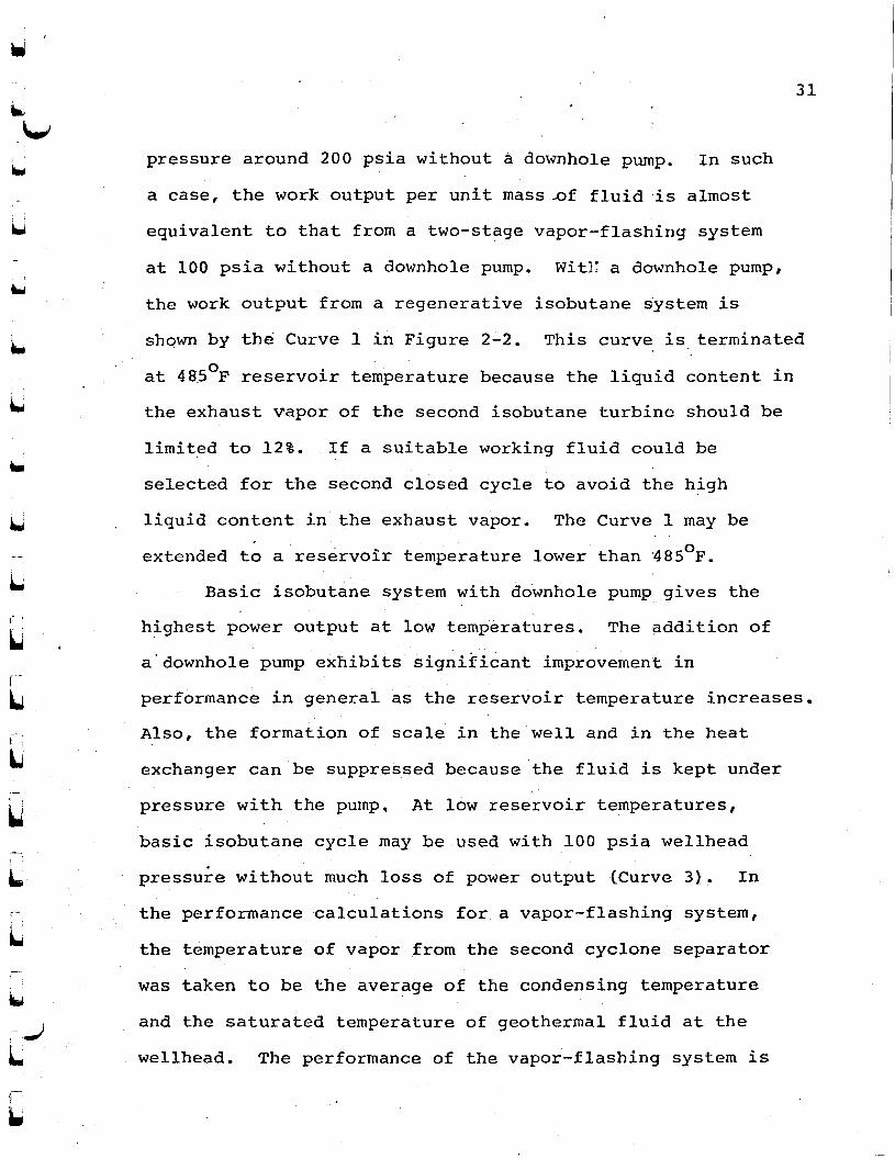
35 .----r----r-----r---,----...;----r----r---""'1
WITH DOWNHOLE PUMP
-- -..,. - -WITHOUT DOWNHOLE PUMP(lOO PSIA WELLHEAD PRESSURE)
30
25
20
15
30L
t l
L
LLLL[
[
L
400 450 500 550
RESERVOIR TEi"J.PERATURE, OF
1 REGENERATIVE ISOBUTANE SYSTEM2 TWO-STAGE VAPOR FLASHING SYSTEM3 BASIC ISOBUTANE SYSTEM4 TOTAL FLOW SYSTEM
600
LL
LFigure 2-2. Effects of Downhole Pump on Work Output
I 1 '
I..
L
r.1LJ
I..-.-I
L.
31
pressure around 200 psia without a downhole pump. In such
a case, the work output per unit mass..of fluid is almost
equivalent to that from a two-stage vapor-flashing system
at 100 psia without a downhole pump. Wit}: a downhole pump,
the work output from a regenerative isobutane system is
shOwn by the Curve 1 in Figure 2-2. This curve is terminated
at 48So
F reservoir temperature because the liquid content in
the exhaust vapor of the second isobutane turbine should be
limited to 12%. If a suitable working fluid could be
selected for the second closed cycle to avoid the high
liquid content in the exhaust vapor. The Curve 1 may be
extended to a reservoir temperature lower than 48SoF.
Basic isobutane system with downhole pump gives the
highest power output at low temperatures. The addition of
a'downho1e pump exhibits significant improvement in
performance in general as the reservoir temperature increases,
Also, the formation of scale in the well and in the heat
exchanger can be suppressed because the fluid is kept under
pressure with the pump, At low reservoir temperatures,
basic isobutane cycle may be used with 100 psia wellhead
pressu~e without much loss of power output (Curve 3). In
the performance calculations for a vapor-flashing system,
the temperature of vapor from the second cyclone separator
was taken to be the average of the condensing temperature
and the saturated temperature of geothermal fluid at the
wellhead. The performance of the vapor-flashing system is

not much improved by using a downhole pump (Curves 2).
The'total flow concept 'system yields the least work
output (Curve 4).because its performance is based on the
engine efficiency of 55% according to the current
technology (20). Through research it is likely that a
nozzle and an impulse turbine may be developed to give the
engine efficiency much higher than 55%. The total flow
concept system can not be recommended until its efficiency
is improved.
In all the previous calculations with a downhole
pump, the pump work has not been accounted since the depth
of the pump and its performance are uncertain. Assuming
the depth of the pump to be 2,000 ft. and a combined
efficiency of motor and pump to be 50%, the work input is
5.14 Btu per pound water, or 1,5 Kwh per l,OOO Ib, water.
So far no reliable pump has been developed to handle hot
brine at such a depth. The application of binary system
depends upon the successful development of downhole pump.
32
f
I..\w
L
LLLLLLLL~
~
r...L'
'-i-t...

! ,
liU
'--
I i
iJ
u
·CHAPTER III
REGENERATIVE HEAT EXCHANGER DESIGN
Introduction
The regenerative heat exchanger is an important and
costly equipment in the regen~rative binary system. Its
cost should be ~ustified before adopting the regenerative
isobutane system. An analysis is being attempted here to
provide the estimates of the overall heat transfer coeffi
cient, the pressure drops in the shell and tubes, and the
cost.
The finned-tube conf~gur~tion for the heat exchanger
provides significant advantages over the plain-tube one. -
when the heat transfer coefficient of one side is very small
as compared to the other side. Finned surfaces of wide .
variety are manufactured commercially, and the three basic
types are: cross-fins, pin-fins, and longitudinal-fins.
The selection of a particular type depends on three factors:
allowable pressure drop, velocity limitations, and fluid
properties.
The amount of accurate and reliable data on finned-
tube heat exchanger is extremely limited, parti~ularly for
units of large sizes. The research program at the
University of Delaware has contributed significantly to an
understanding of heat transfer and fluid-flow mechanisms on

the shell-side of a shel1-apd-tube heat exchanger ~ontaining
plain tubes. Based on the results from this program,
Bell (5) devised a procedure which could be used to predict
,~he shell-side heat transfer coefficient and the pressure
drop. In his procedure, the effects of leakage between tube
bundle and shell, between tube and baffle, and between
baffle and shell on heat transfer coefficient and pressure
drop were shown to be important. Briggs et ale (6)..investigated the technique of Bell and concluded that the
Bell's procedure can be applicable in the shell-side
correlation for finned-tube also. They utilized the method
which was based on the Bell's procedure for the shell-side
calculations of heat transfer coefficient and pressure drop,
and their method is used in this study. For determining the
shell-side heat exchanger tube-sheet geometry, Dunkelberg's
method (9) is used_
Tube~Sheet Geometry
The performance of a regenerative heat exchanger
depends greatly upon the tube configuration and the
characteristics of the fins attached to the tubes.
The baffled shell-and-tube heat excha~ger implements
flows normal to the tube banks in a configuration which
provides convenient piping access. This is accomplished
34
Ii
l..
t !
1.
! ':
I 1
L, 1
L..
L~
Ll'L~
LLLf 1
L
'L.
L
n,!~
UCo
,-
u~ ,-IU
35
by inserting the tube bank longitudinally into the
cylindrical shell and providing segmented baffles normal
to the tube bank to guide the flow. The tube-side fluid
enters and leaves through heade~s and the shell~side fluid
enters and leaves through the nozzles welded directly on the
shell.
This type of arrangement destroys the ideal normal
flow. The fluw through the baffle segment is parallel to
the tubes, and the flow approaching each normal flow section
is neither uniform nor normal. In addition, practic~l
design requires that there be small clearances between the, '
baffle$ and the shell, and between the baffles and the tubes.
Also, if there is a substantial' clearance between the outer
row of tubes and the shell, it leads to significant
bypassing to decrease the heat exchq.nger effectiveness.
Aluminum is an excellent material for heat exchanger
tubes and fins. It is cheap, easy to fabricate, and light
in weight. It has high thermal conductivity and does not
react with isobutane chemically. Copper is a good
alternative, but its cost is higher than aluminum.
Cross-fins are most suitable for the finned-tubes
of a heat exchanger which handles large flow with small
allowable pressure drop. They can be placed at right
angle to the axis of each tube, or to a group of tubes.
Included in this catagory are the helical fin and annular
fin. Helical fins'provide excellent heat transfer

performance, but the fin height is limited by the amount
that the fin can be stretched in wrapping operation.
Annular fins provide ease of fabrication and cause less
pressure drop.
The fin spacing is usually determined by manufacturing
tolerance; the value is usually from 6 to 15 fins per inch
depending on the incentive to minimize the volume of the
heat transfer.matrix. As the number of fins per inch is
increased, the unit can be made progressively more compact.
At the same time, however, it becomes more sensitive, to
clogging by dirt and small irregularities in the fin
spacing. Ten to twelve fins per inch represent a good
compromise.
As the regenerative heat excha~ger operates with
clean fluids at all times, relatively small tubes which
offer high heat transfer rate may be used to make the heat
exchanger compact. However, the pressure drop of fluid
increases as the diameter of tube decreases. Arbitrarily,
tubes of I in. outside diameter are selected.
The fin efficiency is a function of temperature
distribution in the fin, and in turn it depends on the
thermal conductivity, the dimensions of the fins and the
heat transfer coefficient between the fin surface and the
fluid. The influential parameter is Hf/hIKb, where Hf
is the fin height in ft., h is the heat transfer coefficient
in Btu/hr-ft-OF, and X is the thermal conductivity of the
36
!'
"-,-Jf '
~
, 1
L
Lf '
L
LL~
[
LJ
L[
[
[
L.'
L,,",
LI 1
~

l\.J
I..
L
uuuu
~
..,I
U
fin material in Btu/hr-ft-OF, and b is the fin thickness
in ft. Typical fin height is ~ to ~ in.' for general
purposes. The fin efficiency can be adversely affected if
the fin is not integrally or metallu~gically bonded to the
tube by soldering, brazing, or welding.
The tube array plays an important role. It may be
classified as either in-line or staggered. The in-line
tubes tend to'give a somewhat lower pressure drop and
poorer heat transfer because the flow tends to be channeled
into high velocity regions in the center of the lane
between the tube rows. The st~ggered tubes produce better
mixing of the flow over the tube banks and give a higher
pressure drop.
Tube-pitch affects the heat transfer coefficient also.
In practice, a pitch of 1,25 times the outer diameter of
tubes is generally adopted for plain tubes, For finned
tube bundle, the pitch to tube diameter ratio must be
higher because of the protrusion of the fins.
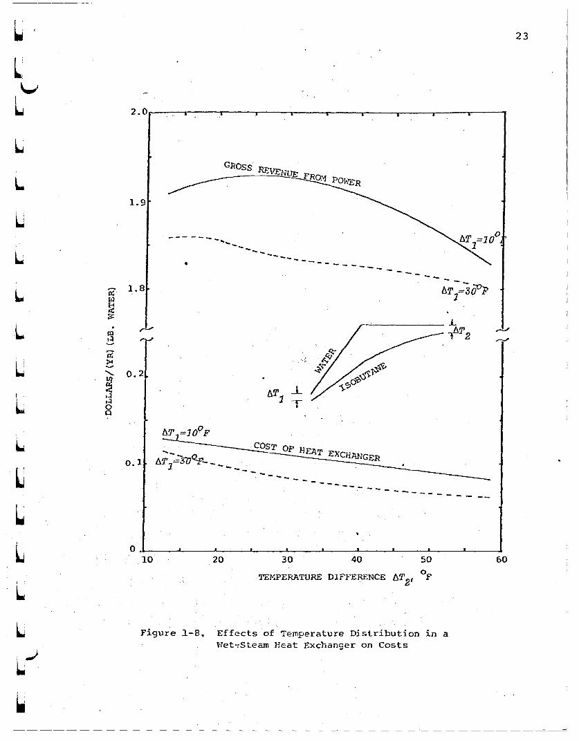
To investigate the problem of designi~g a regenerative
heat exchanger, sample calculations were made for a plant
which processes600op saturated water at 106 lb. per hr, as..
shown in Figure 3-1. Figure 3-2 shows the temperature-
enthalpy relationship of isobutane inside the regenerative
heat exchanger. Superheated isobutane at 95.7 psia and
32lo p enter~ the shell side of the regenerative heat
exchanger. It transfers heat to the compressed liquid
37

6.28MW
120°F 61.0286 x 10 lb/hrx=92.1lkh=-653.0 Btu/hr
Turbine-Generator
Pump(1. 3 MW)
300°F, 700 psia, h=-628.5 Btu/lb
48°F Saturate~-------~---------liquid
h=115.87 Btu!lb
32.75
172°Fh=-6l8.5 Btu/ 1-----:-......1.-----:-""1 126°F, 700 psia
lb '----iP'---r---(-o---' h=-766. 4 Btu/lb
MAIN HEATEXCHANGER
Turbine-Generator
524°F, 2000 psia1.82 x 106 lb(hrh =-476.0 Btu/lb
600°F Saturated liquid106 lb/hrh=6l6.8 Btu!lb
Figure 3-1. Flow Diagram of a Regenerative Isobutane System

r.=::1 £1
340-625 -615'
Isobutane Enthalpy, Btu!lb
-605 -~95 -585 -575 '-565 ..555 -545 -535
320
300
280
260
Cz.t 240° ...~ 220::;,E-c~~ 200~.~E-c
180
160172°F
140
120126°F
-780 -760 -740 -720 ...700 -680 -660 -640 . -620
Isobutane Enthalpy, Btu!lb
Figure 3-2. Temperature-Enthalpy Relationship of Isobutane in a Regenerative Heat ExchangerW\0

40
Based on the aforementioned considerations on the tube
basic design data pertaining to the tube sheet geometry
Lr 1-\.,
LLLLL[
CL[
[
L[
Annular
0.884 in.
1.00 in ..
0,058 in •
0.015 in.
1.875 in.
0.4375 in.
3.884 ft2/ft
0.2314 ft2/ft
l1
l6,83
Type of fins
Inside tube diameter, d."7-
Outside tube diameter, do
Fin diameter, W
Fin thickness, b
Number of fins/inch, NN~J
Fin height, Hf
Outside surface area, Ao
Inside surface area, A."7-
Surface area ratio, AlA.o "7-
Thermal conductivity of aluminumalloy, K
. Tube thickness, ttube
isobutane and exists from the heat exchanger at 172°F. The
liquid isobutane enters the tube side at 126°F and 700 psia
and comes out at 300oF.
configuration and characteristics of fins, the following
were established:
Equilateral triangular pitch, p 2.8 in.
A 60 in. outside diameter shell was selected with two
passes on the tube side and single pass on the shell-side.
Utilizing the method devised by Dunkelberg (9) for
Lf '....
L1-
L

lu
, ,
u determining the tube-sheet geometry, and following the TEMA
Standards (19), the variables which prescribe' the tube
sheet geometry were determined as follows:'
41
. ,
r i
u
Shell thickness, ts
Shell inside diameter, dS
Allowable clearance between theoutside tubes and shell, q
•
Shell material
Baffle cut, B
Window area, SW
Mean cross-flow area, Sm
Total number of tubes in theexchanger, N
Baffle spacing, LLBNumber of tubes in the window, Nwt
0.5 in.
59.0 in.
0.475 in •
steel
40 %of shell insidediamet"er
1038 sq. in.
954 sq. in.
367
39 in.
137
8.5
5.0
i. j .
Ll
'-i- ...,I~.
Figure 3-3 depicts the tube layout.. In the
calculations, the following properties of isobutane at
the bulk mean temperature were used (10):

t 1
L..42
L
u
(
LL
L
2.8"0.5"3671.00"0.884"1. 875"39"
~.. thick
Tube Pitch =Shell Thickness =Number of Tubes =Tube Outer Dia. =Tube Inner Dia. =Fin Outer Dia. =Baffle pitch =
+
+
+
+...+
-+
-t
...
of
-t
-+
...
...
-t
+
-+
+
t +
+
+
+
+
+
-+
+ -+ -+. -+2.8"1.-- --I
-i + ...
...
t
-+
-+
of
...
+
+
...
+
Scale 10:1
+ + -t + ...
1" -+ -+ -tFlow of
-+ of -l -+Shell-side... -i of -t
Fluidof!-+J-+!-tJ-t
+ -+ -+ +
+
+
+ ...
-t
of -t 0of ... G
-t -i +0... 0
-i +~-t(!)
... -t 0... 0
-t -+ G)+ + + -+ -+ -+ + ... -+ -t 0
~ -+ 8+ ... 0
+ of 0... -+ + -+ + ... of + +. CD--of---+---+--f----+----+--i- - -+ -0--
-+ + + 8+ + G
+ of CD
...
....
-o\0
Figure 3-3. Layout of Tubes in Shell
t •
L\..
L,'L.

43
Viscosity, ~, Ib/hr~ft
Thermal conductivity, K~
Btu/hr-ft-OF
Density, p, Ib/ft3
constant-pressure specificheat~ C , Btu/lb-oF
P
Tube-Side' Shell-side(213°F, (247°F,
700 psia) 95.7 psia)
0.1694 0.1161
0,042 0.034
28.57 0.8
0.775 0.525
Overall Heat Transfer Coefficient,'Uo
The overall heat transfer coefficient Uo can be
expressed in terms of the individual resistances, as shown
by Briggs et al. l6}:
l/U =l/hL+rf+ro+(A /A.)(l/h.}+(A +A.)(riJ+rmo 0 ~ ~ 0 ~(3-l)
I.l. ..;U
where hL
is the shell-side heat transfer coefficient for the
heat exchanger with bypass. and leakage in Btu/hr-ft2 - oP,
rf is the f~n resistance in hr-ft2-op/Btu, ro is the outside..
fouling'factor in hr-ft2-op/Btu, A. is the inside heat. ~
transfer area in ft 2 , A is the total outside heat transfero
area in ft 2 , h. is the inside heat transfer coefficient in~
Btu/hr-ft2- 0 P, ri is the inside fouling factor in hr-ft2-oF/Btu
and rm is the metal resistance in hr~ft2_0F/Btu. For a
finned-tube configuration, the outside heat transfer area

44I i
f
includes the surface area 'of the fins. The various terms
involved in equation (3-1) were calculated with the
procedure given by Briggs et al., except the uses of Sieder
\w~f '
La
Land Tate equation and Briggs and Young equation with some
modifications for the calculations of the inside coefficient
,'L
believed that. the modified Sieder and Tate equation, and
are more accurat~ and applicable. The results of the
Briggs and Young equation used for the calculations of h.1-
h •• This is because of lack of the'experimental data for1-
'the geometry under the present consideration. It is
ll~L
[
[
LUCLL
f'
l.
I '
L\-..
1-
L
30960
4.5 ft/sec.
0.00983 ft.
0.0129
0.77183
30.,0
0.7105
0.9432
0.2573 sq. ft.
Hydraulic radius~ rh
Reynold's number for the fluidin the shell, Re
Velocity of fluid in the tubes, V.1-
Ratio of window heat transferarea to total heat transferarea, r
Colburn modulus, j
Correction factor for the effectof baffling on shell sidecoefficient, ~.
Effective number of crossflowconstrictions in series, NC
Correction factor for row numbereffect on heat transfercoefficient, X
t
Bypass area, ABP
calculations are;

flU
UFractional bypass area factor, FF
BP
Viscosity ratio correction£actor, (~/~ )0.14
lJ
Shell side heat transfercoefficient with no bypassingor leakage" hNL
Diameter of the hole in thebaffle, dhB
Number of tubes through eachbaffle, NBT
Baffle-to-tube leakage area, STB
Central angle, e
0.0388.
1.0
300.0 Btu/ (hr)(ft2) (oF)
1.90625 in.
218
0.1405 sq. ft.
158.10
45
iiu(..)
U
Baffle diameter, dB
Leakage area between baffleand shell, SSB
Total baffle leakage area, SL
Ratio of SL/Sm
Shell side heat transfercoefficient with bypassand leakage, hL
Assumed fin efficiency, ~f
Fin resistance, rf
Inside fouli~g factor, rifA /A.)o "Z-
Log-mean area of the tubewall, A
mean
Metal resistance, rm
Tube side heat transfercoefficient, h.
"Z-
Overall heat transfercoefficient, Uo
58.7 in~
0.108 sq. ft.
·0.2485 sq. ft.
0.0375
257.03 Btu/(hr}(ft2) (oF)
0.8
0.001024 (hr){ft2 } {OF} /Btu
o•00 8 4 15· (hr)(ft2) (oF)/Btu
0.2463 sq. ft.
0.Ob0762 {hr}(ft2 ) (OF) /Btu
393.6 Btu/(hr)(ft2) (OF)
17.45 Btu/(hr}(ft 2 ) (OF)

46
Total Heat Transfer Area Ao~t and Tube Length L per Pass
As shown in Figure 3~1, the flow ofisobutane is
accomodated by three sets of heat exchangers in parallel.
Each set consists of 4 single shell-pass, double tube-passes
heat exchangers and is equivalent to a 4 shell-passes, 8 tube-
passes heat exchanger, as shown in Figure 3-4~ The heat
f h. ' . 0 6transfer Q 0 eac set of heat excha~gers 1S 48.26 x ~
Btu/hr~
The logarithmic mean temperature difference was found
in terms of the terminal temperature difference as shown.
in Figure 3-2, and it must be compensated later for the
irregularities of the specific heats of isobutane. The
corrected mean temperature difference is the product of the
logarithmic mean temperature difference and the correction
factor F, which is a function of heat capacity ratio Rand
the required heat exchanger effectiveness P(19). The
number of passes affects the value of F.
Knowing the value of overall heat transfer coefficient
2 0Uo in Btu/hr-ft - P, the total heat transfer requirements
Q in Btu/hr, and the corrected mean temperature difference
6Tm~eorr in °P, the total surface area required for the
h h . f 2 lId h I I heat exc anger Ao t 1n twas ca cu ate. T e tota engt~
of tubing ~equired is equal to Ao t/Ad~where Ao is the out-~
side surface area per unit length of tube in ft2
• The length
L of the tube per pass in ft. can be found by dividing the
total length of the tubing required by the number of tube
passes.
Lt '< ,---,-
\...)
LLLL~
L[
~
CC(
CLl
L

-=:'1 C.' r· .--- .
-I'
695 psiar 300°F
Expansion J~ : .
SECTION AA
14'-0"\-
jf\j n·r ~ ~ "-'0" • 3' ...3" 1==.
\. ~ ~
.~
I I., . ,. ~ .- , -Ie
'"'" .) ,I ~" thick E 1--IE·--
1"1 -(' ~ t.J • J
0" ~.@ {.- r==F
\.!
'CB~"'-.J I
I
" .. ~--
5'-
5'-
367 1. A" OD0.887" IDTubes; FinDia. 1. 875'.'
A --r95.71 r- - 695 psiapsia II 300°F
3210F
SECTION BB
Tube-side fluidShell-side fluid
Figure 3-4. Schematic Diagram of a 4 Shell-Passes8 Tube-Passes Regenerative Heat Exchanger

..The irregular variation of specific heat of isobutane
at constant pressure causes the minimum temperature
48
-~i
Ldifference 6T • to be located in the middle of the heat
m'Ln
exchanger (Figure 3-2). Because of this effect, a further
r 'L
values were calculated for each equivalent 4 shell-passes,
With the aforementioned assumptions, the followingLL~
CC[
[
C
~
LLL
\....L.
U
0.89
0.85
132,966 sq. ft ..
154,428 ft2
14.0 ft.
Heat excahnger effectiveness, P
Heat capacity ratio, R
Log-mean temperaturedifference, 6T. mean
Corrected mean temperaturedifference, 6T
m.,corJ:'
Total outside heat transferarea required, A t
0.,
Actual outisde heat transferarea
Length of tube per pass, L
correction was made, and the corrected mean temperature
difference becomes lSoP.
8 tube-passes regenerative heat exchanger:
the friction factor f in the shell was calculated bys
The pressure drop on the shell side was calculated
in the same way as originated by Briggs et a1., except that
Pressure Drop on the Shell Side

~'
luU
Robinson and Briggs equation (18). The calculated values
for the shell side pressure drop are:
49
The friction factor for the flow of fluids inside
the tubes can be found from the Moody's diagram in terms
u
~
~."..' :'."
~
UU
Velocity of isobutane in thewindow, Vw
Cross-flow velocity basedon S ~ Vm m
Geometric mean velocity,V =(V xVw)J.;
2 mFricition factor for the
flow of fluid in the shell, Is
Pressure drop through the windowwith the correction factorfor leakage, b.PW
Pressure drop through each end,I1PE
Total pressure drop in the shell,I1Ps
Pressure Drop on the Tube side
31.7 ft/sec.
·31.7 ft/sec.
31.7 ft/sec.
0.299
0.1925 psia
0.623 psia
4.6 psia
of the Reynold's number. The calculated values for
determining the tube side pressure drop are:
~
UlJ.-I
Mass velocity of the fluid inthe tubes, G. .
1-
Velocity of the,fluid insidethe tube, v.
1-
462534.7 Ib/hr-ft2
4.5 ft/sec.
Friction factor of flow onthe tube side, f.
~
Pressure drop through thetubes, ~P.
~
Pressure drop through theheaders, ~p~
n
Total tube side pressure drop,
~PtotaZ
0.024
2.27 psia
1.99 psia
4.26 psia
50
I !
~
I 1
-~
~t ;
U,'
L
LI 1
L
Cost Estimation
The actual cost of a large heat exchanger has to be
quoted by the suppliers after the design is completed. At
present, it is impossible to make a precise estimate of the
cost; however, the unit cost is believed to be in the range
of $0.50 per sq. ft. of the heating surface area
approximately (11). Thus, the total cost o~ the three heat
exchangers is about $200,000, not including the installation
cost. The sample design in this section is intended to
demonstrate the feasibility of the construction of a large
regenerative heat exchanger. The designs were not optimized.
By applying the te~hniques of optimization (16), the heat
'transfer area and the cost could be significantly reduced.
LL~
~
cCLC[
LL
L

~
wu~
~
.~
WU
CHAPTER IV
CONCEPTUAL DESIGN OF A REGENERATIVE ISOBUTANE SYSTEM
Introduction
'The geographical location of the plant can have a
strong influence on its success as a commercial venture.
But, the site selection of a geothermal power plant is
unusually inflexible and depends basically on the location
of producing r~servoirs. The factors. that must be evaluated
in a study of plant location are: availability of energy
source, geographical considerations, market for power
produced, ecology effect, environmental impact, and cost of
the plant. No site can satisfy all the requirements, and
the final selection has to be based on comparing the
favorable and unfavorable features of each site.
This .chapter describes the major components of a
10 MW regenerative isobutane plant, assuming that the
osaturated water enters the plant at GOOF.
Flow Diagram
The operating pressures and temperatures were
determined by heat balances as discussed in Chapter I. The
major components, their connecting ,piping, important valves

and controls are shown in Figure 4-1. There are three
fluids in the system. The first is the geothermal fluid
that supplies heat energy for the power generation. The
second is the working fluid isobutane and the third is the
cooling water. Heat is rejected by the exhausted isobutane
in a condenser to the cooling water which is recycled
through a cooling tower. Table 4-1 lists the pressure,
temperature, enthalpies and the flow rates at the.respective points as noted in Figure 4-1.
Consideration was given to the size of the plant.
The experimental plant must be large enough to experience
all the problems of a production plant. The. size of the
plant must fit the normal production rate from at least one
well. On' the other hand, an unnecessarily large pilot
plant might become wasteful. Hence, the unit is designed
for a net power of 10 MW. Heat is transferred from the
geothermal fluid to the isobutane at a rate of 175 x 106
Btu/hr., which gives the gross output of 13.7 MW from the
two turbo~generators. The power requirement of the pumps
and other auxiliaries is 3.7 MW.
The saturated 6000 F geothermal brine flows into the
plant at 0.35 x 10⁶ Ib/hr. The pressure is maintained
above its saturation pressure by a brine pump in order to
prevent flashing throughout the heat exchanger. This pump
has sufficient capability to force the used brine into the
reservoir through the reinjection well. Four main heat
52
l..I 1l .
. > .....
~I...)
U11iIJ
Lf
L
LI .
L
~
LU
UL[J
ll
\..L
L

r- r·· r
VILoJ
Ieobut.ane rlU
Normally Open ValveNormally Cloied ValveControl Valve
TC Temperature ControlPC Pressure ControlSC Speed ControlFC rlCN ControlLC Level ControlHWC Load ControlCC Conductivity Control
IIOT~TIONSI
® TO reinjection veilSaturated Liquid Water
Haln 'led \>wrlpU.S HW)
@hobutane2000 pda, 13 eOr
Turblne-cenerator
.-.!...;...;..__~><)_v.;,;ent
~::::::~!::::::::~To Condenler
To Receiver
®
lb,lhr
1Cn0ekout Drvm
Haln Heat Exchangera
To ReCliver
r-__~........;T.:o_CO:.;;:ndenllr
@·1sobutane1"5 plla, 524°,0.62 • 10 lb/hr
riqure 4-1. Flow Dla9r~ of 10 HW Regeneratlve Ilobutane Power 'lant

Table 4-1. Pressures, Temperatures, Entha1pies and FlowRates of a 10 MW Plant
54
~ ,I i
I,
i •
;..,;,,-:,I'L
Pressure, Temperature, Enthalpy, Flow Rate,Point psia of Btu/lb 106 Ib/hr
1. 1,800 600 616.8 0.35
2. 1,750 148 116.0 0.35
3. 2,000 138 -757.1 0.62
4. 1,975 524 -476.0 0.62
5. 96 321 -538.9 0.62
6. 91 172 -618.5 0.62
7. 96 120 -766.4 0.98
8. 700 126 -770.7 0.36
9. 695 300 -628.5 0.36
10. 96 120 -653.0 0.36
LULLLr~
[
L~
~
L[
L\.~
L

~.
VL.
L
uUI. 11~
Uu
L,-IU
55
exchangers are provided in series with the valves so that
any of the exchangers can be taken out of service for
cleaning or repair while the plant is in operation. A
bypass is provided to allow all the hot brine to be returned
to the reinjection line in case of emergency.
A receiver is placed underground below the condenser
to store liquid isobutane. During normal operation, the
main feed pump circulates 0.62 x 10⁶ pounds of isobutane.per hour at a total head of 2,000 psia. A knockout drum is
used to prevent liquid isobutane from entering the ~urbine.
Superheated vapor at 1975 psia and 5240 P expands through
the isobutane turbine to drive the main generator, which
produces 11.5 MW power. The exhaust vapor from the turbine
at 32loP,' 95.7 psia flows through the shell of the
r~generative heat exchanger. It then condenses in a shell-
and-tube condenser, and the condensate returns to the
underground receiver by gravity.
The low-pressure feed pump draws isobutane from the
receiver at a flow rate of 0.36 x 10 6 lb/hr and pressurizes
it to 700 psia. The compressed isobutane passes through
the tubes of the regenerative heat exchanger and comes out
as superheated vapor at 3000 P and 695 psia. The superheated
isobutane then expands in the second isobutane turbine to
produce 2.2 MW power. The exhausted vapor from the second
turbine is at l200 P and 95.7 psia and has 92.1% quality.,
Cooling water at 80 0 P enters the tube-side of the

56
6condenser at a, flow rate of 4.6 x 10 Ibjhr and leaves at
110oF. To conserve the supply of cooling water, cooling
towers are used. Because the evaporation process increases
the concentration of dissolved solids in cooling water,
continuous blow-down and make-up water are provided.
'. Specifications of Equipment
1. Regenerative Heat Exchanger
In Chapter III, a preliminary design of 3 regenerative
heat exchangers for a saturated 600 0 p geothermal brine at
106 Ibjhr has been made~ A separate design of a regenerative
heat excha~ger for a saturated 6000 p geothermal brine at
0.35 x l06 Ibjhr is not attempted here since the present
design serves as a preliminary estimate only. One heat
exchanger as described in Chapter III shall be used in
the conceptual plant. It consists of four 5 ft, diameter'
shells. Each shell has two tubes passes, There are 367
tubes of 14 ft, length per shell~ The tubes are of 1 in,
,outside diameter and 0,058 in. thick, The arrangement of
tubes and heat exchangers is shown in Figures 3-3 and 3-4.
Each tube has 11 1.875 in. 0.0, annular fins per inch,
and the fin thickness is 0.Ol5 in. The tubes and the fins
are made of aluminum alloy. The equilateral triangular
pitch for the tubes is 2.8 in. The shell is made of carbon
~ 1rI...f ~
t--.,~
~,', '
rl.
I '
L
L
LL
~,
L
L

~!
VLJ
L
uLI
~
.W
~
~
U! I
,r 1 /
U!
~
I
LI
U
L.J
U-l
57
steel and is 0.5 in. thick. The baffle cut o~ the heat
exchanger is 40% of the shell inside diameter. The overall
he~ttransfer coefficient of th~ heat exch~~ger surface is
·2017.45 Btu/hr-ft - F, and the total area of the heati~g
surface is-154,428 ft 2 • The isobutane vapor at 700 psia
from the low pressure feed pump flows through the tubes of
. the heat exchanger at 0~36 x 10 6 lb/hr~ The exhaust
isobutane at ~2loF, 95.7 psia,from the main turbine flows
at a rate of 0,62 x 10⁶ lb/hr to heat the isobutane in the
tubes. An expansion joint on the shell of each heat
exchanger is recommended to compensate for the different
thermal expansions of the shell and tubes~
2. Main Heat Exchangers
The temperature distribution in a main heat excha!1ger
was discussed in Chapter ~, and the. guidelines of the design
was adopted from the proof-of-concept design by Bechtel
Corporation (4); There are three 4 ft. 6 in. diameter main
heat exchangers of counterflow( shell-and~tube type in series
for normal operation( and the fourth one is a stand-by
for ~epair and for periodic cleani!1g by chemical,process.
The scale-forming brine flows in the shell for easy cleaning
while isobutane flows at a rate of 0.62 x 10⁶ Ib/hr in the
tubes. Each heat exchanger has a heat transfer surface
area of 10,435 ~t2, consisting of 2,292 tubes of 3/4 inch

.-
diameter by 16 BWG thick by 24 ft. long. The tube material
is 90-10 copper-nickel. Isobutane comes out of the
exchanger at 5240 F and 1,975 psia. The total heat load
for the three heat exchangers is 175 x 106 Btu/hr. The
overall heat transfer coefficient for the heat exchangers
is estimated to be 175 Btu/hr-ft2- OF during normal operation.
3. Receiver
The receiver is a steel underground tank of 40,000
gallons capacity. During operation, most of the working
fluid- is in circulation. Valves are provided so that all
the isobutane can be drained into the receiver. The system
shall be purged with carbon dioxide before the isobutane
is charged into the system.
4. Isobutane Turbines
The overall efficiency of isobutane turbine is
estimated at 85%. According to Anderson (15), this
efficiency can be easily attained, and there is no
technological problem to build a reliable isobutane turbine.
Radial inflow type turbines with rotational speed around
7,200 rpm may be used. The two turbines are geared to
their respective generators which operate at 3,600 rpm by
I 1.-\-jt '
L
r 'I!...
LL(
[
~-
~
~
[I '
L
U
LL,
W

i 'IiIii
uuu
~"
I.~
U
U
59
the use of a speed-reduction geprbox. Special shaft seals
have to be provided to avoided leakage of isobutane, and
a high pressure lubrication system is necessary.
5. Condenser
The condenser shall be conventional shell-and-tube.
type with isobutane flowing"through the shell side. The
recommended tube diameter for the condenser is from 3/4 to
l~ in., with velocities of cooling water from 5 to 7.5 ftl
sec. The number of tube passes could be either one or two.
The effective tube length is from 25 to 30 ft. per tube pass.
The condensing temperature is 1200 P for normal operation.
The total heat load for the condenser is 136 x 106 Btu/hr,
The flow rate of isobutane in the condenser is 0,98 x 10 6
Ib/hr, assuming 300 p temperature rise of the cooling water.
Aluminum-brass or other aluminum alloys are the recommended
material for the tubes. The material of shell may be
carbon steel.
6. Cooling Towers
The dry cooling towers and .the natural draft towers
are not practical for a 10 MW power plant. A mechanical
draft tower operating on forced or induced fan is more

60
desirable. For an induced draft tower, the cro$sflow
design offers certain distinct advantages over the
counterflow arrangement because the distance of air travel
is independent of the fill height. Both the height of the
fill and the distance of air travel of a crossflow tower
can be adjusted to minimize the loss of draft. Also, the
pumping head of crossflow tower is lower than that of
counterflow tower. The forced draft tower has to encounter.the disadvantage of non-uniform air distribution and partial
recirculation of vapors. An induced draft crossflow tower
is, thus, recommended for a 10 MW geothermal power plant.
The usual approach temperature is between 14 and 220F,
with cooling range between 15 and 3SoF (1). The make-up
water can" be supplied to the concrete basin of the tower
from a canal or a storage pond. Provision for chemical
treatment should be made, if necessary. The blowdown should
be deaerated and then pumped into the brine reinjection line,
in order to minimize the corrosion in pipeline and
reinjection well.
7. Knockout Drums
In order to ensure that no dirt particles or droplets
of liquid isobutane may enter the isobutane turbines, two
knockout drums should be provided. The knockout drum is a
f •
Lf •
L
L-L
L~
L[
~
~
~
~
lL
!~
~
W
w
L
U..~
~
61
cylindrical carbon steel vessel with internal baffles.
Liquid isobutane from the drums is drained to the receiver
by level control.
8. Piping
Carbon steel is suggested for isobutane and brine
pipes. The m~in isobutane lines should be of 15 in. diameter
for the liquid and 21 in. for the vapor. For brine flow,
12 in. diameter pipes are recommended (14). These values
were calculated by assuming that the velocity of liquids
in pipe is 5 ft/sec., and that the allowable pressure drop
for the isobutane vapor is l psi per 100 ft. of pipe length,
Insulations of suitable type and thickness should be
provided according to the temperature and service of the
pipe, finished with mechanical protection such as metal
or waterproofing jackets. Provisions should be made for
thermal expansion of high temperature pipes.
Controls and Instrumentation
In the start-up sequence, the cooling system is
started £irst. It provides the heat sink for the process,
The brine system is started next, and then the isobutane
system. The controls and instrumentation for each sub-

system are:
A. Brine System
In case of the shut-down of the plant, the by-pass
valve is opened, and the main brine valve is closed.
Pressure, temperature controls and recorders are provided
at the inlet as well as the outlet of the main heat.exchangers. A modulating valve at the outlet of the main
heat exchanger$ a~justs the brine flow rate to control the
'temperature of isobutane as it leaves the main heat
exchangers.
B. Isobutane System
The receiver should be monitored by a·level control.
A pressure relief valve connects the receiver to a flare
stack. A valve at the inlet of the main heat exchanger
along with a trip valve stops the flow of isobutane during
an emergency shutdown. Temperature and pressure controls
.are provided at the isobutane outlet of the main heat
exchangers to sense the condition of isobutane. The
pressure controller adjusts the main feed pump speed to
maintain the designed pressure. The temperature controller
adjusts the main turbine control valve which regulates the
isobutane flow rate to maintain designed temperature
62
11IIW
I •
!,. --._~
\-i
L
1 1
I..• t
L
L"LL~
~
ULC
Cr 1
....
! '..~. 1
L
L

lv
Iw
U
LU
U
UUU'U~
u, I
U
I ....1-
U
U
63
conditions. Level controls are provided at the knockout
drums. The main turbine as well as the secondary turbine
should be equipped with a stop valve and a control valve.
Regulation is accomplished by a turbine generator controller
that senses the speed of the turbine, electrical load, and
temperature of isobutane at the outlet of the main heat
'exchangers or the regenerative heat exchanger. Turbine
trip signals include high turbine speed, high exhaust
pressure, low oil pressure, high bearing temperature; and
generator trip.' ; Upon trip the main turbine stop valye and
the stop valve at the isobutane entrance to the heat
exchangers close. The turbine,bypass valve opens to allow
the flow of isobutane to the condenser. For condenser,
controlled vent valve allows the discharge of gases to the
flare stack. Normally during shutdown, isobutane system has,
liquid in the receiver and vapor throughout 'the rest of the
system. However, for initial start-up or after the system
has been opened for maintenance or repair, an additional
procedure is required to purge the air that has been
introduced into the system. 'To accomplish this, the air
is first evacuated'with a vacuum pump, then carbon dioxide
is introduced into the piping system, and all piping paths
are sequentially opened. and closed, with the carbon dioxide
and residual air being vented out through the flare stack.
The flare stack is provided with an electric ignitor type
pilot flame to monitor isobutane concentration.

64
C. Cooling System
Local cooling water temperature and pressure
indicators should be provided at the both ends of the
condenser. The conductivity control for the cooling tower
is used to control the salt content in the cooling water~
Cost Estimation
The estimated capital cost of a 10 MW basic isobutane
plant for 3800 p saturated liquid water with additional
facility for experimentation, conceptually designed by
Bechtel Corporation (4), is $23 million, of which $7.5
million is for experimental facilities. The equipment
cost of major components is estimated to be $6,190,000.
A preliminary estimate of the equipment cost of the
10 MW regenerative isobutane power plant under this study
is given in Table 4-2. The unit costs from the reference
(11,17) were scaled up to take care of the inflation at
about 6% annually. Without any experimental facilities,
the capital costs of the plant is expected to be $10,915,000.
It is relatively low in comparison with the conceptual plant
of Bechtel Corporation's design because the costs of
engineering, contingency and some equipment are different.
For the same flow rate of the same geothermal fluid,
the net power production of the basic isobutane plant is
! 't '.., !
! ,-~LLLW
LJ
~
[
[
LLLL[f •
LI '.
~
" I
I.

uu,~
w
wLUL
~
.~
~
~
65
8.5 MW with the same main heat exchanger, assuming that
the superheat of exhaust isobutane is removed by a
desuperheater. The total installed cost is lowered to
$9,375,000 because of the omission of the second turbine,
the regenerative heat exchanger and its auxiliaries, and
the itemized costs are given in Table 4-3. If the power
cost is 2¢/Kwh, the revenue loss of the basic plant is
$262,000 per year. At 12% of the investment charge, the
payback period of the additional equipment for regenerative
plant is 11 years.

66
Table 4-2. Capital Cost of the Major Components of a 10 MWRegenerative Isobutane Power Plant
Installed CostDescription ($1,000)
I 1, I
U
a = Modern Cost-Engineering Techniques by Popper (17).
b = Heat Exchanger Design by Ozisik and Fraas (11) •.c = Electrical Power Generation Using Geothermal Brine
Resources for a Proof-of-Concept Facility byBechtel Corporation (4).
Main Heat Exchangers (a)
Regenerative Heat Exchanger (b)
Turbine-Generator Modules (c)
Condenser Ca)
Receiver ea)
Pumps and Drives eel
Cooli!1g Tower Ca) .
Knockout Drums Cal
Auxiliary Systems {el·
Electrical ~quipment lcl
Concrete and Eartnwork (cl
Piping, Insulation and Valves ec)
Instrumentation Ccl
Site Improvement eel
Building Costs eel
Engineering Costs
Contingency
Total Installed Cost
Bases for Estimates:
900
150
1,500
500
30
525
250
75
220
530
720
2,320
270
220
805
1,000
500
10,915
IL.
i'
L~ ..
'-L

Lv...
Table 4-3. Capital Cost of the Major Components of a8.5 MW Basic Isobutane Power Plant
67
L
Description
Main Heat Exchangers (a)
Turbine-Generator Module (c)
Condenser (a)
Receiver (a)
Pumps and Drives (c)
Cooling Tower "(a)
Knockout Drum (a)
Auxili~ry Systems (c)
Electrical Equipment (c)
Concrete and Earthwork (c)
Electrical Bulk Materials ec)
Piping, Insulation and Valves
Instrumentation (c)
Site Improvement (c)
Building Costs
Engineering Costs
Contingency
Total Installed Cost
Bases for Estimates:
Installed Cost($1,000)
900
1,000
500
30
350
250
35
220
530
720
400
1,800
270
220
750
950
450
9,375
i-;: .IUj I
~
a = ~odern Cost-Engineering Techniques by Popper (17)"
b = Heat Exchanger Design by Ozisik and Fraas (11).
c = Electrical Power Generation Using Geothermal BrineResources for a Proof-of-Concept Facility byBechtel Corporation (4).

CHAPTER V
CONCLUSIONS
At present, there are basically three different
systems for converting energy in geothermal fluid into
power: vapor-flashing system, total flow system, and binary
system. A comparison of the power production processes was
made on the oasis of work output in Kwh per 1,000 pounds of
geothermal fluid for self flowing wells with wellhead
pressure of 100.psia and for wells with downhole pumps.
For simplicity, the assumptions were made that the enthalpy
of· the geothermal fluid in the reservoir is approximately
equal to that at the wellhead, that the thermodynamic
propertie~ of geothermal fluid may be approximated by those
of water, and that the pressure effects on the properties
of fluid are negligible. The results showed that the
performance of the two-stage vapor-flashing system is not
appreciably improved by using a downhole pump (Figure 2-2).
The total flow system is simple, but its success depends
mainly on the development of a reliable machine with
'sufficiently high"thermal efficiency. The regenerative
isobutane system is impractical, if the geothermal fluid
temperature is below 380o p. But, when the brine temperatures
range from 485 to 600op, the regenerative isobutane system
with downhole pump exhibits superi~r performance as compared
I ~
i..f '!
- ...~;
11
L
LLL[
L(
[
L[
(
LLLL
\."LaI '1
U
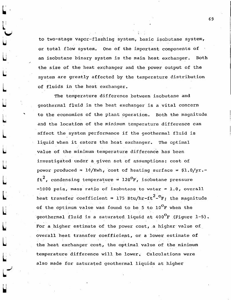
~I
L~
'-i
"
to two-stage vapor-flashing system, basic isobutane system,
or total flow system. One of the important components of
an isobutane binary system is the main heat exchanger. Both
the size of the heat exchanger and the power output of the
system are greatly affected by the temperature distribution
of fluids in the heat exchanger.
The temperature difference between isobutane and
geothermal fluid in the heat exchanger is a vital concern
to the economics of the plant operation. Both the magnitude
and the location of the minimum temperature difference can
affect the system performance if the geothermal fluid is
liquid when it enters the heat exchanger. The optimal
value of the minimum temperature difference has been
69
i ..;.
~
~
investigated under a given set of assumptions: cost of
power produced = l¢/Kwh, 'cost of heating surface = $1. O/yr.
ft2 , condensing tempera~ure= l20op~ isobutane pressure
=1000 psia, mass ratio of isobutane to water = 1.0, overall
heat transfer coefficient = 175 Btu/hr-ft2
- 0 P; the magnitude
of the optimum value was found to be 5 to lOop when the
geothermal fluid is a saturated liquid at 4000 p (Figure 1-5).
Por a higher estimate of the power cost, a higher value of
overall heat transfer coefficient, or a lower estimate of
the heat exchanger cost, the optimal value of the minimum
temperature difference will be lower, Calculations were
also made for saturated geothermal liquids at higher

70
temperatures under the same assumptions, and the results
indicate that the optimal value remains around 5 to 10°F.
The location of the minimum temperature difference can be
adjusted by varying the mass ratio of water to isobutane
[Figure 1-61. It was found that the point of minimum
temperature difference should be as.close to the water exit
as possible in most cases; however, this is not a rule. As
to the cases of two-phase geothermal fluid, the heat transfer
area was calculated by dividing the heat exchanger into a
condensing section and a non-condensing section. In such
cases, the optimal temperature differences at the exit and
the inlet of the heat excha~ger (Figure 1-8) were evaluated.
The heat transfer coefficient for the condensing section
2 0was assumed to be 500 Btujhr-ft ~ F. For one calculation,
the other assumptions were: mass ratio of water to
isobutane = 0.43, temperature of. geothermal .fluid = 400oF,
mass fraction of vapor in geothermal fluid = 0.292, power
cost = l¢jKwh, heating surface cost = $1.Ojyr~ft2, condensing
temperature = l20oF. It was found that the optimal
temperature differences were 100F at the exit and 200
F at
the inlet. In another calculation, the geothermal fluid
was assumed to be at 312°F, 10.3% quality, and there were
no significant changes in the values of optimal.temperature
differences. Thus, it can be concluded that for preliminary
design the suggested minimum temperature difference in the
heat exchanger is in the range of 5· to 10°F at a location
f 1I •
I
~--
} 1
L
LlLC[
[
~
~
[
lLL
\...,
L.f 1...

~ i~'
, !
L\.,f
~
L
u
LLUU
UU
UU-l
I I~
near the water exit when the geothermal fluid is pumped out
from a reservoir, and that the suggested temperature
differences at the exit and the inlet of a heat exchanger
are 100F and 200F respectively if the geothermal fluid
emerges from a well by natural forces. Additional heat
balances and economic analyses are recommended for every
specific situation.
The power output of the system is affected
significantly by the isobutane pressure. The optimum
pressures as a function of the water temperatures a~ the
wellhead were determined by heat balances as given in
Figure 1-3.
The equipment of regenerative isobutane system is
similar to that of basic system except ,the addition of
regenerative heat exchanger. The designs of regenerative
heat exchanger were studied, and the method of Briggs et al.
(6) was found su~table for calculating the overall heat
transfer coefficient and the pressure drops in the shell
and tubes. For a hypothetical plant which is supplied with
6000F saturated geothermal liquid, the overall heat transfer
coefficient was found to be 17.5 Btu/hr-ft2- oF. In the
conceptual design of a 10 MW plant, one heat exchanger of
14 ft. tube length was used. It has 4 shell-passes and
8 tube-passes as shown in Figure 3-4. Aluminum alloys
were suggested for the tubes and the fins of the heat
exchanger since they do not react chemically with isobutane
71

and are cheaper than copper. The size of heat exchanger
may be reduced by applying the techniques of optimization.
Although the design is conservative, it does demonstrate
the technical feasibility of constructing a large
regenerative heat exchanger, and it furnishes a basis for"
economic evaluation.
At the end of this study, a conceptual design was
made for a 10 ~ isobutane regenerative plant which uses
600°F saturated geothermal liquid as the energy source.
The flow diagram of the plant is given in Figure 4-1, to
show the arrangement of counterflow heat exchangers,
turbines, knockout drums, shel1-and-tube condenser,
isobutane feed pumps, cooling tower, regenerative heat
exchanger, and underground receiver. The capital cost of
the plant is estimated at $10,915,090. As compared to the
estimated cost of the basic isobutane plant, the adoption
of the regenerative system can definitely be justified if
the power cost is 2¢/Kwh or higher.
72
I ~
Li 'I
~ .....~I
[
L[
LUL~
LL"
LL~
LC

U
l\.IU
uULLULUULU
L
~
i -/-
W
REFERENCES
1. Ahluwalia, R.K., M.S, Thesisi university of Hawaii,December 1974.
2. American Society of Heating, Refrigeration and Airconditioning Engineers Handbook of Fundament~
American Society of Heating, Refrigeration andAir-Conditioning Engineers, Incorporated, New York,1972, p. 629 ~
3. Austin, A.L., G.H. Higgins and J.H. Howard. The TotalFlow Concept for Recovery of Energy from GeothermalHot Brine Deposits, UCRL-5l366, Lawrence LivermoreLaboratory~ University of California," April 1973.
4. Bechtel Corporation, Electric Power Generation UsingGeothermal Brine Resources fora Proof-of-ConceptFacility, A report submitted to-Energy Research andDevelopment Administration, May 1975.
5. Bell, K.J. Final Report of the Co-operative ResearchProgram on Shell and Tube Heat Exchangers, BulletinNo.5, University of Delaware EngineeringExperimental Station, Delaware, January 1963.
6. Briggs, D.E., D.L. Katz and E.H. Young. "How to DesignFinned-Tube Heat Exchangers", Chemical EngineeringProgress, Vol. 59, No. 11, November 1963, p. 49.
7. Chou, J.C.S. and R.K. Ahluwalia. Characteristics ofVapor-Flashing Geothermal Plant, Hawaii GeothermalProject, Technical Report No.6, University ofHawaii, November 1974.
8. Chou, J.C.S., R.K. Ahluwalia and E.Y.K. Woo.lIRegenerative Vapor Cycle with Isobutane as WorkingFluid", Geothermics, Vol. 3, No.3, 1974.
9. Dunkelberg, Stephen B. "A Dimensionless Method forDetermining Shell-Tube Heat Exchanger Tube-SheetGeometry", Journal of American Society of Heating,Refrigeration and Air-Conditioning Engineers,Vol. 4, December 1962, p. 48.
10. Engineering Standards, Philips Petroleum Company,May 1967.
J

74
11. Fraas, Arthur P. and M. Necati.Ozisik. Heat ExchangerDesign, John Wiley and Sons, New York;-!965, p. 141.
12. Holt, B., A.J.L. Hutchinson and Douglas S. Cortez."Geothermal Power Generation Using the B.inaryCycle", Geothermal Energy Magazine, Vol. 1, 1973,p. 43.
13. James, R. "Optimum Wellhead Pressure for GeothermalPower", New Zealand Engineering, Vol. 22, 1967,p. 221.
14. Kuong, J.F. Applied Nomography, Vol. 2, GulfPublishing Company, Texas, 1968.
·15. Kruger, P., C. Otte (editors). "The Vapor-TurbineCycle for Geothermal Power Generation", GeothermalEnergy, Stanford University Press, Stanford,California, 1973, Chapter 8, p. 163.
16. Peters, M.S. and Klaus D. Timmerhaus. Plant Designand Economics for Chemical Engineers, McGraw-HillBook Company, New York 1968, p. 281.
17. Popper, Herbert and the Staff of Chemical Engineering.Modern Cost-Engineering Techniques, McGraw-HillBook Company, New York, 1970.
18. Robinson, K.K. and D.E. Briggs. "Pressure Drop of AirFlowing Across Triangular pitch Banks of FinnedTubes", Chemical Engineering Progress SymposiumSeries, Vol. 62, 1962, p. 2.
19. Standards of Tubular Exchanger ManufacturersAssociation, Tubular Exchanger ManufacturersAssociation, NBW York, Fifth Edition, 1968.
20. Weiss, H., R. Steidel and A. Lundberg. PerformanceTest of a Lysholm Engine, UCRL-S1861, LawrenceLiverm-ore Laboratory, University of California,July 1975.
III
1 1
, 'I..I .
~
UL[J
U[
[
CC
L
~ ~
W\.~