jfe’s waste to energy technology€™s environmental solutions 5 waste to energy plant rdf...
TRANSCRIPT

JFE’s Waste to Energy Technology
10, March 2016

About JFE
JFE’s WTE Technology

Group Structure
3
5
43,000
Net Sales(million $)
Employees 25,000
JFE Steel
1,300
Net Sales(million $)
Employees 16,800
JFE Shoji Trade
JFE Holdings (est. 2002)
8,500
Net Sales(million $)
Employees 3,200
6,500
Net Sales(million $)
Employees
2,300
Japan Marine United
Est. 1912 Est. 1951
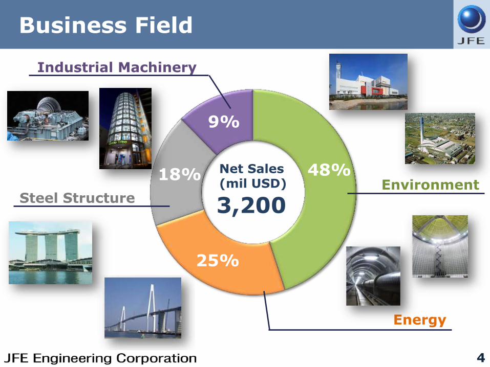
Business Field
4
Environment
Energy
Steel Structure
Industrial Machinery
Net Sales (mil USD)
3,200
48%
25%
9%
18%
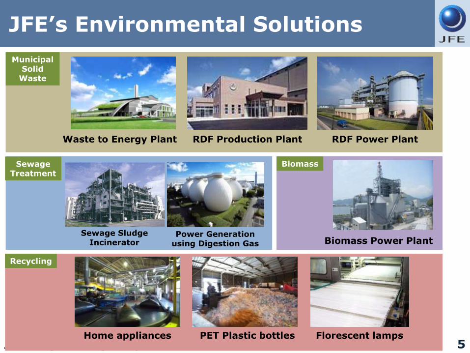
JFE’s Environmental Solutions
5
Waste to Energy Plant RDF Production Plant RDF Power Plant
Sewage Sludge Incinerator
Power Generation using Digestion Gas Biomass Power Plant
Home appliances PET Plastic bottles Florescent lamps
Municipal Solid
Waste
Sewage Treatment
Biomass
Recycling

●Gasifying & Melting
●Stoker & others
EPC
Operation 68 Plants
Maintenance 115 Plants
O&M
WTE presence in Japan since 1968 171 plants (354 Furnaces)
JFE’s Track Record in Japan
6


About JFE
JFE’s WTE Technology
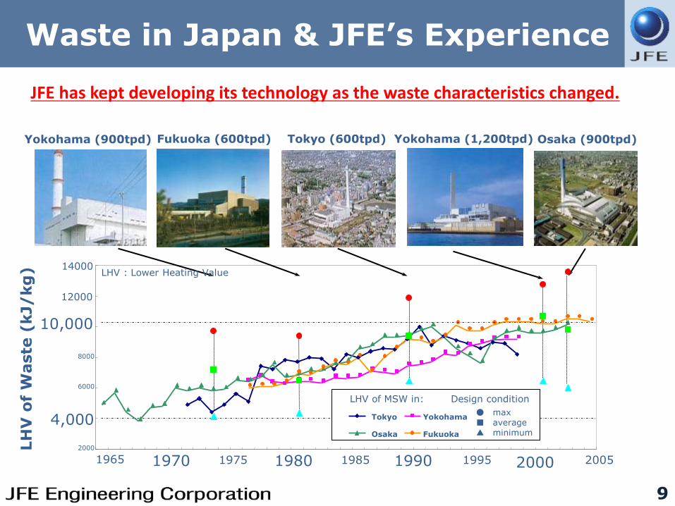
Waste in Japan & JFE’s Experience
9
Yokohama (900tpd) Fukuoka (600tpd) Tokyo (600tpd) Yokohama (1,200tpd) Osaka (900tpd)
LH
V o
f W
aste
(kJ/
kg
)
2000
4,000
6000
8000
10,000
12000
14000
1965 1970 1975 1980 1985 1990 1995 2000 2005
LHV : Lower Heating Value
LHV of MSW in: Design condition
● max ■ average ▲ minimum
Yokohama
Fukuoka Osaka
Tokyo
JFE has kept developing its technology as the waste characteristics changed.

Typical Process Flow of WtE Plant
10

Furnace Profile
11
Hopper
Chute
Waste feeder
JFE Hyper Grate system
Boiler
Furnace
Intermediate ceiling
Waste Exhaust gas
Bottom ash
High temperature Air nozzle

2-Way Flue Gas Furnace
12
Intermediate ceiling
Secondary Combustion Zone
For unburned gas : Oxidation reaction
2CO+O2 → 2CO2 For combustion gas : Reduction reaction
NOx +NH3 → N2+H2O
Complete Combustion
Achieved
Unburned gas CO, H2, NH3
Combusted gas O2, NOx, CO2
Drying Zone
Combustion and post-combustion Zone

Stable Combustion with Low Excess Air
13
Stable Combustion Region
Blowing high-temperature air forms stable combustion region.
Thermal decomposition is accelerated.
Stable combustion is achieved even with low excess air ratio.
Low NOx, CO, DXN
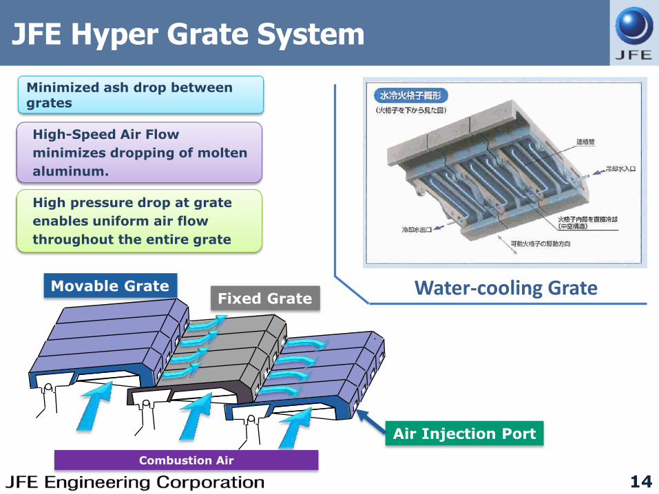
JFE Hyper Grate System
14
Minimized ash drop between grates
High-Speed Air Flow
minimizes dropping of molten
aluminum.
Movable Grate Fixed Grate
Air Injection Port
High pressure drop at grate
enables uniform air flow
throughout the entire grate
Combustion Air
Water-cooling Grate

Stoker Furnace (Fujimi, TOKYO)
Completion March 2013
Capacity 288 ton/day (144TPD× 2 lines)
Power Gen. 9.7MW
Flue gas treat. Gas cooling tower, NaOH injection system, dry-type flue gas treatment system, bag filter, deNOx reactor
Ignition Loss of Bottom Ash
≦3%
Design calorific value of waste
Min. LHV
5,850kJ/kg
1,400kcal/kg
Ave. LHV
9,610kJ/kg
2,300kcal/kg
Max. LHV
13,380kJ/kg 3,200kcal/kg
Waste Pit
Emission Performance
Regulatory Standards
Dust & Fly Ash
<0.001g/Nm3 0.04g/Nm3
SOx Ave. 2.25ppm 46ppm
NOx Ave. 21ppm 250ppm
HCl Ave. 1.4ppm 430ppm
DXN
0.00000014ng-
0.00014ng-TEQ/Nm3
0.1ng-TEQ/Nm3
Hg <0.005mg/Nm3 Unregulated
15
Entrance Weighing Bridge
Waste Crane Control Room

Thank you for your kind attention.