jelly filled cable - indian railwayrdso.indianrailways.gov.in/works/uploads/file/handbook on...
TRANSCRIPT
CAMTECH/S/2001/JFC/1.0 1
JELLY FILLED CABLE MARCH’’ 2001
JELLY FILLED CABLE
1. INTRODUCTION
A Cable can be defined as a number of insulated metallic conductors bunched in acompact form by providing mechanical protection and electrical insulation.
The cable in which core is fully filled with petroleum jelly, a water-resistantcompound, is called jelly filled cable.
Cable can be classified as Underground Cable (laid under ground), Submarine cable (laid under water), Aerial cable (laid over head) and Indoor cable ( laid along the wallsof building). However, in Railways only Underground and Indoor (Switch Board)Cables are used.
This handbook covers Construction. Laying, Jointing, Testing, and Maintenance of(I) Polythene Insulated Polythene Sheathed Jelly Filled underground Cable with Poly-Al moisture barrier & (II) Jelly filled underground quad cable (4 Quad or 6 quad) asper Indian Railway Standard Specifications No. TC 41-97 & TC 30-97 respectively.
2. BRIEF DESCRIPTIONS
Jelly filled cable is an underground cable having polythene as insulation onconductors and the inter-spaces between the conductors is fully filled with petroleumjelly. Petroleum jelly prevents ingress of moisture and water inside the core in theevent of any damages to the cable. The Cable is circular throughout its length and isfree from any physical defects.
Jelly filled cable is wound on strong wooden drums. The length of cable on any drumis of 500 meter + 10% unless single longer lengths are specified by purchaser forspecific application. The diameter of the yoke of the drums is not be less than 20times of the overall diameter of the cable. Both ends of the cable is kept inside thedrum To get access to the cable ends battens are is painted by red colour arrow.

CAMTECH/S/2001/JFC/1.0 2
JELLY FILLED CABLE MARCH’’ 2001
2.1 MARKING ON CABLE
To enable proper identification of the cable, the following information is embossed,engraved or printed on the polythene jacket in case of armoured cable, and on thesheath in case of for un-armoured cable. All the marking is in white or yellow colour:a) Name/Trade mark of the manufacturerb) IRS Specification numberc) Year of manufactured) Length (Sequential marking)e) Cable drum No.f) No. of pairs/conductor size ( Example : 100 pairs/0.63mm)
This marking is exists throughout the length at intervals of one metre.
2.2 MARKING ON CABLE DRUM
The following information is stencilled on the cable drum:
a) Manufacturer’s name, brand name of trade markb) IRS Specification No.c) Type of cabled) Nos. of pairs and diameter of conductore) Length of cable on the drumf) Direction of rotation of drum (by means of an arrow)g) Approximate gross weighth) Country and year of manufacturei) Drum No.
2.3 ADVANTAGES OF U/G CABLE
1. Overhead lines may come in contact with trees, bushes, etc. and cause lowinsulation.
2. Due to natural calamities and ravages of humans beings, overhead lines areprone to a higher fault incidence.
3. Due to headway considerations the maximum number of pairs on a pole routeis limited to 16.
NOTE: By using underground cable all these disadvantages can be minimised. Jellyfilled cable has additional advantage over non-jelly filled cable. It preventsingress of water & moisture inside the cable.
CAMTECH/S/2001/JFC/1.0 3
JELLY FILL
2.4 USES
In Railways Polythene Sheathed Jelly Filled Cable with Ploy-Al moisture barrier isused for providing telephone connections to the subscribers.
Jelly filled quad cable is used for special purposes like control circuits, Axle countersetc. in RE and Non-RE areas.
The different sizes of cables to be used for various telecommunication circuits are asfollowing table:
Sr. No. Size of conductor Circuit1 0.5mm (6.5 lb/ mile) Subscriber’s connections not exceeding 5
km.2 0.63mm (10 lb/ mile) Subscriber’s connections and different
lines 5 to 10 km long.3 0.9mm (20 lb/ mile) Tie lines in the same local area4 Quaded cable, .9mm copper
conductor (20lbs/mile) Telecommunications control circuits &Axle counter circuits.
3. CONSTRUCTION
3.1 CONSTRUCTION PIJF TELEPHONE CABLE
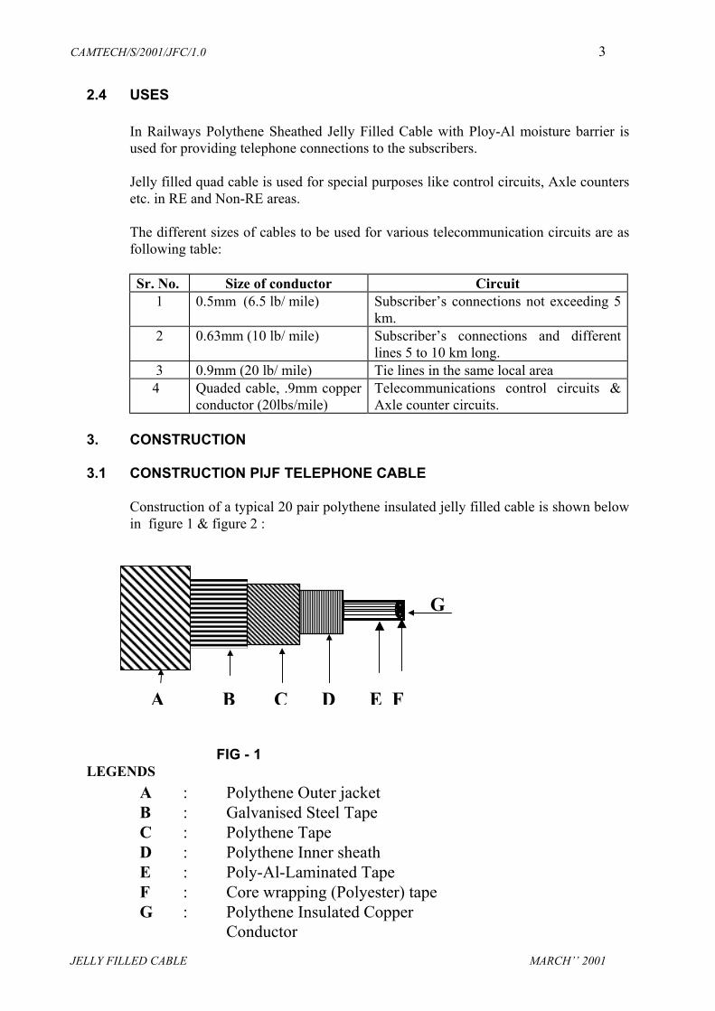
Construction of a typical 20 pair polythene insulated jelly filled cable is shown belowin figure 1 & figure 2 :
LEGE
G
A B C D E F
ED CABLE MARCH’’ 2001
FIG - 1NDS
A : Polythene Outer jacketB : Galvanised Steel TapeC : Polythene TapeD : Polythene Inner sheathE : Poly-Al-Laminated TapeF : Core wrapping (Polyester) tapeG : Polythene Insulated Copper
Conductor

CAMTECH/S/2001/JFC/1.0 4
JELLY FILLED CABLE MARCH’’ 2001
A POLYTHENE INSULATED CONDUCTOR
Conductors are provide for carrying electric current from one place to another.Conductor is consist of a solid round wire of annealed high conductivity copper,smoothly drawn, nominally circular in section, uniform in quality & resistance andfree from defects.
INSULATION
Insulation is provided to insulate the conductors with each other and other parts ofthe cable .
Insulation
Conductor
G
F
E
D
C
B
A
LEGENDS
A : POLYTHENE INSULATED COPPER CONDUCTORB : PETROLEUM JELLYC : POLYSTER TAPED : JELLY FLOODINGE : POLY-AL-LAMINATED TAPEF : POLYTHENE INNERSHEATHG : POLYTHENE TAPE (DOUBLE LAYER)H : GALVANISED STEEL TAPE (DOUBLE LAYER)I : POLYTHENE OUTER JACKET
FIG - 2 : TYPICAL CROSS SECTION OF PIJF CABLE

CAMTECH/S/2001/JFC/1.0 5
JELLY FILLED CABLE MARCH’’ 2001
PE compound covering is provided on conductors for electrical isolation betweenthem. Insulation should be free from any joints or repairs. It shall fit closely on theconductor but not adhere to it so that it is possible to remove it easily without damageto the conductor.
The insulation resistance between each conductor shall not be less than 5000 Megaohms per kilometre at room temperature.
PAIR
Two insulated conductors is twisted together with uniform lay to form a pair. Eachpair takes one telephone circuit.
Polythene Insulated Polythene Sheathed Jelly Filled Cable is of different sizesvarying from 10 to 200 pairs with nominal conductor dia 0.5 or 0.63 or 0.9mm.Thestandard cable sizes is 5, 10, 20, 50, 100 and 200 pairs.
UNIT
A number of twisted pairs laid up to form a group is constitute the unit.
B PETROLEUM JELLY
The cable core is fully filled with a water resistant compound petroleum jelly which isfully compatible with the polythene insulation, binders and tapes used in the cable.
C POLY-AL-LAMINATED TAPE
After application of petroleum jelly a closed helical or longitudinal lapping of a non-hygroscopic and non-wicking polyester tape is laid over the cable core. A polythenecoated aluminium tape is applied longitudinally on the core with a minimum overlapof 6mm. The Poly-Al-laminate is mechanically and electrically continuous throughoutthe length of the cable.
D POLYTHENE INNER SHEATH
The cable core complete with filled petroleum jelly and layer of Poly-Al-Laminatedtape is surrounded by a close fitted sheath of polythene. The sheath is reasonablecircular and free from pin holes, joints and other defects.
E POLYTHENE TAPE
Two close helical lapping of polythene or polypropylene tape is applied overpolythene inner sheath to provide sufficient mechanical protection. This providesbedding to armour.
F GALVANISED STEEL TAPE
The sheathed cable is then armoured with two layers of galvanised steel tape. Eachlayer is applied helically in the same direction.

CAMTECH/S/2001/JFC/1.0 6
JELLY FILLED CABLE
Joints in the armouring tape is kept to the minimum. Wherever joints are madeadequate corrosion protection is provided on both sides. If any rusty portions arenoticed on the tape the same should be painted with suitable anticorrosive paint.
G
POLYTHE
Finally threasonably
3.2 CONSTR
Constructifigure 5:
J I H G F E D C B A
LEGENDSA: PE INSULATED CORE FILLED F: BARIUM CHROMATE TAPE WITH JELLY G: PVC INTERMEDIATE SHEATHB: MYLAI TAPE H: BEDDING TAPEC: POLY TAPE I: ARMOURINGD: PE INNER SHEATH J: OUTER SHEATHE: ALUMINIUM WIRE SCREENING
Fig - 4
MARCH’’ 2001
NE OUTER JACKET
e armoured cable is tightly jacketed with polythene. This jacket is circular, free from pin holes and other defects.
UCTION OF QUADED PIJF CABLE
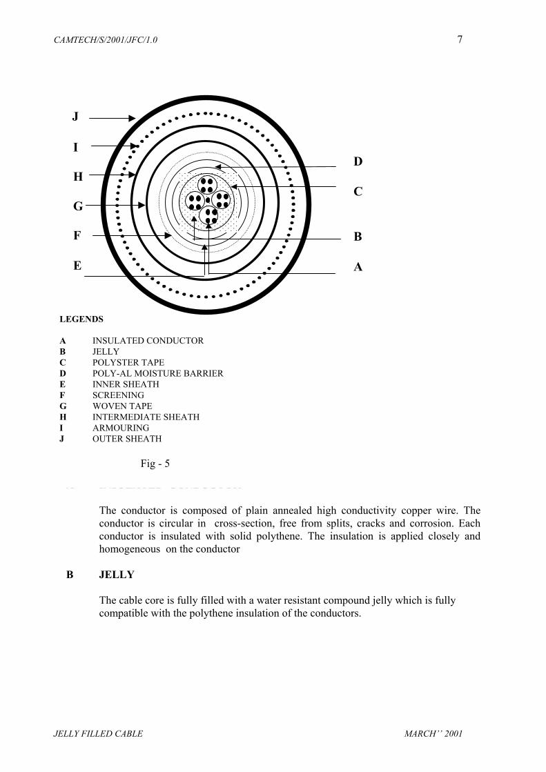
on of a typical jelly filled quad cable (4 quad) shown below in figure 4 &
CAMTECH/S/2001/JFC/1.0 7
JELLY FILLED CABLE MARCH’’ 2001
A INSULATED CONDUCTOR
The conductor is composed of plain annealed high conductivity copper wire. Theconductor is circular in cross-section, free from splits, cracks and corrosion. Eachconductor is insulated with solid polythene. The insulation is applied closely andhomogeneous on the conductor
B JELLY
The cable core is fully filled with a water resistant compound jelly which is fullycompatible with the polythene insulation of the conductors.
LEGENDS
A INSULATED CONDUCTORB JELLYC POLYSTER TAPED POLY-AL MOISTURE BARRIERE INNER SHEATHF SCREENINGG WOVEN TAPEH INTERMEDIATE SHEATHI ARMOURINGJ OUTER SHEATH
Fig - 5
I
H
G
F
E
J
D
C
B
A

CAMTECH/S/2001/JFC/1.0 8
JELLY FILLED CABLE MARCH’’ 2001
C POLYSTER TAPE
After application of the filling compound a close helical or longitudinal lapping of apolyester tape is applied over the cable core. The tape is impregnated or flooded withjelly.
D POLY-AL MOISTURE BARRIER
Polythene coated aluminium tape is applied longitudinally on the core with aminimum overlap of 6mm.
E INNER SHEATH
Cable is sheathed with polythene. Sheath is circular, free from pin holes, joints andother defects.
F SCREEN
The cores with inner sheath is surrounded by a reasonably close fitted screen ofaluminium in the form of wires/strips.
G WOVEN TAPE
The aluminium screen is wrapped with a single layer of woven tape impregnated withbarium chromate.
H INTERMEDIATE SHEATH
Further protection for the screening is provided by extruded PVC circular sheath overscreening.The colour of this intermediate sheath is grey.
I ARMOURING
The galvanised steel tape armouring is applied tightly over the intermediate sheathwith two layers.The direction of the lay of the armour is opposite to that of the outermost layer of screening.
J OUTER SHEATH
The outer sheath is applied over the armouring. The colour of this outer sheath shallbe black.

CAMTECH/S/2001/JFC/1.0 9
JELLY FILLED CABLE MARCH’’ 2001
4. COLOUR SCHEME
4.1 COLOUR SCHEME FOR PIJF TELEPHONE CABLE
The colours are applied on insulation of each conductors in such a way that pairs canbe identified easily. The colour scheme of pairs and wires in a unit is in accordancewith the table 3 given below:
COLOUR CODE FOR CONDUCTOR INSULATION
PAIRNo.
1st WIRE(Tip)
2ndWIRE(Ring)
1 WHITE BLUE2 WHITE ORANGE3 WHITE GREEN4 WHITE BROWN5 WHITE GREY6 RED BLUE7 RED ORANGE8 RED GREEN
PAIRNo.
1st WIRE(Tip)
2ndWIRE(Ring)
9 RED BROWN10 RED GREY11 BLACK BLUE12 BLACK ORANGE13 BLACK GREEN14 BLACK BROWN15 BLACK GREY16 YELLOW BLUE17 YELLOW ORANGE18 YELLOW GREEN19 YELLOW BROWN20 YELLOW GREY
TABLE - 3
The different colours of the binder tape is readily distinguishable under normallightning condition. The colour scheme of binder tape is in accordance with table 4for unit identification.

CAMTECH/S/2001/JFC/1.0 10
JELLY FILLED CABLE MARCH’’ 2001
COLOUR CODE FOR TAPE OR BINDER FOR UNIT IDENTIFICATION
UNIT NUMBER COLOUR OF BINDER
1 BLUE2 ORANGE3 GREEN4 BROWN5 GREY
TABLE - 4
NOTE :
In 10 pair units, cables colour code specified for pairs, 1 to 10 is used. In 20 pair units, cables colour code specified for pairs, 1 to 20 is used. The number of pairs with respect to the colour scheme is only for the purpose of
identification of pairs, the actual numerical sequence of the pairs may not be insistedupon.
4.2 COLOUR SCHEME FOR JELLY FILLED QUADED CABLE
The colour scheme of polythene insulated quads is as per table given below :
COLOUR OF THE CONDUCTORINSULATION
QUAD NO.
AWIRE
B WIRE
CWIRE
DWIRE
1 WHITE ORRANGE RED GREY2 WHITE BLUE RED GREY3 WHITE BROWN RED GREY4 WHITE GREEN RED GREY5 WHITE YELLOW RED GREY6 WHITE BLACK RED GREY
Wire A and wire B forms a pair. Similarly wire C and wire D forms a pair.
4.2.1 QUADDING
Four insulated conductors is stranded to form a star quad. In a quad, two conductorsdiagonally opposite forms one pair and the remaining two diagonally conductorsforming the second pair. The quad is held together firmly by means of an openhelical whipping of cotton/nylon yarn or coloured tape.

CAMTECH/S/2001/JFC/1.0 11
JELLY FILLED CABLE MARCH’’ 2001
The lays of the conductors forming the quads is differ with adjacent quads. The lay ofthe conductor is so chosen that the cross-talk between the cable pairs is minimum.
The colour scheme of the quad whipping is in accordance with the table given below:
QUAD NUMBER COLOUR SCHEME
1 ORANGE2 BLUE3 BROWN4 GREEN5 YELLOW6 BLACK
4.2.2 LAYING UP
The quads is assembled to form a symmetrical core with a right lay. Polythene stringsof required diameter is used as fillers, if necessary, for proper circular core formation.
Each quad is retain its position in the cable with reference to the other quads.
5. STORING AND TRANSPORTATION
Cable drums shall have easy access for lifting and rolling.
When rolling the cable drum either for unloading or transportation, the drum shallalways be rotated in the direction of the “arrow” which is marked on the drum.
The drum shall not be rolled over objects that could cause damage to the protectivebattens of the cable.
When unloading is carried out from the vehicle the drum shall not be dropped on theground directly to avoid damage due to impact. Fork lifter or ramp shall be used.
During all stages of storage, it is essential that the ends of the cable are effectivelysealed by end cap or in any other approved manner to avoid water entry into the cable.
It is desirable that cable drums are stored in covered shed to protect against directexposure to sun.
Cable drums shall not be stacked on flat side. Suitable stoppers shall be placed forstability of the drums.
6. CABLE LAYING
CAMTECH/S/2001/JFC/1.0 12
JELLY FILLED CABLE MARCH’’ 2001
6.1 PLANNING
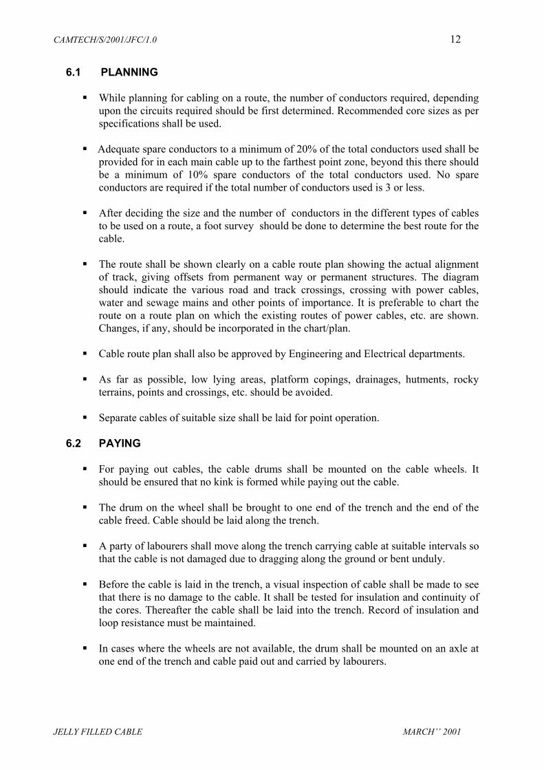
While planning for cabling on a route, the number of conductors required, dependingupon the circuits required should be first determined. Recommended core sizes as perspecifications shall be used.
Adequate spare conductors to a minimum of 20% of the total conductors used shall beprovided for in each main cable up to the farthest point zone, beyond this there shouldbe a minimum of 10% spare conductors of the total conductors used. No spareconductors are required if the total number of conductors used is 3 or less.
After deciding the size and the number of conductors in the different types of cablesto be used on a route, a foot survey should be done to determine the best route for thecable.
The route shall be shown clearly on a cable route plan showing the actual alignmentof track, giving offsets from permanent way or permanent structures. The diagramshould indicate the various road and track crossings, crossing with power cables,water and sewage mains and other points of importance. It is preferable to chart theroute on a route plan on which the existing routes of power cables, etc. are shown.Changes, if any, should be incorporated in the chart/plan.
Cable route plan shall also be approved by Engineering and Electrical departments.
As far as possible, low lying areas, platform copings, drainages, hutments, rockyterrains, points and crossings, etc. should be avoided.
Separate cables of suitable size shall be laid for point operation. 6.2 PAYING
For paying out cables, the cable drums shall be mounted on the cable wheels. Itshould be ensured that no kink is formed while paying out the cable.
The drum on the wheel shall be brought to one end of the trench and the end of the
cable freed. Cable should be laid along the trench.
A party of labourers shall move along the trench carrying cable at suitable intervals sothat the cable is not damaged due to dragging along the ground or bent unduly.
Before the cable is laid in the trench, a visual inspection of cable shall be made to seethat there is no damage to the cable. It shall be tested for insulation and continuity ofthe cores. Thereafter the cable shall be laid into the trench. Record of insulation andloop resistance must be maintained.
In cases where the wheels are not available, the drum shall be mounted on an axle atone end of the trench and cable paid out and carried by labourers.

CAMTECH/S/2001/JFC/1.0 13
JELLY FILLED CABLE MARCH’’ 2001
In no case the drum shall be rolled off on to the road for laying the cable and thecable dragged on the ground for laying purposes.
Whenever mechanised equipment is used, the work shall be carried out by a trainedoperator under the supervision of SE/JE (Telecom.)/ incharge of the work.
Trenching and cable laying work shall be carried out under the supervision ofSE/JE(Telecom.)/in-charge of the work.
Where the cable drum is in damaged condition the cable may be placed on ahorizontal revolving platform.
In no case shall the cable be unwound by taking off from the side of the drum as thiswill cause formation of twist in the cable.
Paying out of cable should be done by rotating the cable drum and not by pulling thecable with excessive force.
6.3 LAYING CABLE ABOVE GROUND
In AC electrified areas cables shall be laid underground only. Cables for out doorcircuits should not normally be laid above ground. In exceptionable cases where itbecomes unavoidable, the following precautions should be taken:
(i) The cable should be suspended in wooden cleats, from cable hangers or in any other
approved manner so that no mechanical damage occurs to the cable even underexposed condition.
(ii) The cable supports shall be so spaced as to avoid sag. (iii) In station yards, cable shall be laid in suitably protected ducts. (iv) Indoor cable should normally be laid on ladders, channels or in any other approved
manner. The cable should be neatly tied/laced.

CAMTECH/S/2001/JFC/1.0 14
JELLY FILLED CABLE MARCH’’ 2001
6.4 CABLE LAYING (UNDERGROUND)
Cables may be laid underground, either in trenches, in ducts, in cement troughs, inpipes or in any other approved manner.
6.4.1 LAYING THE CABLES IN DUCTS
• RCC or any other approved type of ducts may be used for laying the cable. • The ducts shall have suitable covers. • The ducts shall be of such design as to prevent water collecting in the duct. • When cables are laid in rocky area, it is desirable to protect them with split RCC
ducts of suitable design. • Where it is necessary to take the cable between the tracks, it shall be carried in
trunking kept sufficiently below the ballast level. • Where several cables of different categories have to be laid in the same trench, they
shall be placed as far as possible in the following order starting from the main trackside, so that in the event of failures the maintenance staff may easily recognise thedamaged cables:
i) Telecommunication Cable ii) Signalling Cable or Cables iii) Power Cable
RAILWAYTRACK
TELECOMCABLE
SIGNALCABLE
BRICKS
POWERCABLE
LAYING OF UNDERGROUND TELECOM CABLEWITH OTHER CABLES

CAMTECH/S/2001/JFC/1.0 15
JELLY FILLED CABLE MARCH’’ 2001
Cables belonging to the Department of Telecomm. or the Electrical Department mustnot be laid in the same trench along with Signal & Telecom. cables. A distance ofapproximately 10 cm. must be maintained between telecommunication and signallingcables. The signalling cables must be separated from power cables, carrying morethan 110 volts by a row of bricks between them.
6.4.2 Laying
Cable shall be laid generally as per instructions given. However, special precautionsto be taken in the station yards etc. where a number of other utilities may be existing,may be detailed in a joint circular issued by the Civil Engineering, Signalling andElectrical departments of the Railway.
• The cable laid parallel to the track shall normally be buried at a depth of 0.80 metres
from ground level while those laid across the track must be 1.0 metre below the railflanges. However, in case of rocky soil, the depth may be reduced suitably. When itconcerns the laying of tail cables which serve the track apparatus, etc, the depthshould not be less than 0.50 metres.
• The width of manually made cable trenches should be commensurate with number of
cables. The minimum width shall be kept as 0.3 metre. The bottom of the cable trenchshould be levelled and cleared of any sharp materials. In the soft ground, the cableshould be laid at the bottom of the trench previously levelled. In the rocky ground, thecable should be laid on a layer of sand or sifted earth of 0.05 metre thicknesspreviously deposited at the bottom of the trench. In both the cases the cable shouldbe covered with a layer of sand or sifted earth of 0.10 metre thickness and thereaftera protective cover of trough or a layer of bricks should be placed. Bricks should belaid on the cable breadth-wise. The trench should be back filled by sifted earth up toits original level.
Cable Crossing
• When a cable has to cross the track, it should be ensured that:-
I) The cable crosses the track at right angles,ii) The cable does not cross the track under points & crossings, andiii) The cable is laid in RCC/GI pipes, while crossing the track.iv) ACC/GI pipes should be used for road crossing.
• Wherever practical, the cable may be taken underground across the drain bed at asuitable depth for crossing small culverts. nallahas with low flood level. If it is notpossible then GI pipes should be used on culverts or drains for crossing the cables.
• When cables have to cross a metallic bridge, they should be placed inside a metallictrough which may be filled with bituminous compound, as an anti-theft measure, withsealing compound. The cable should be supported across the bridge in a mannerwhich would involve minimum vibrations to the cable and which will facilitatemaintenance work. Adequate cable length to the extent of 2 to 3 metres shall be made

CAMTECH/S/2001/JFC/1.0 16
JELLY FILLED CABLE MARCH’’ 2001
available at the approaches of the bridge. From surface level to embankment of thebridges, brick channel should be made for carrying the cables.
• Cable markers wherever provided should be placed at suitable intervals ( about 30meters) and at diversion points.
• While laying the cables in accordance with the above instructions, the followinginstructions should be adhered to for the safety of the track:
i) Outside the station limits, the cables should generally be laid at not less than 5.5
metres from the centre of the nearest track. iii) Within the station limits, the trenches shall preferably be dug at a distance of not
less than 3 metres from the centre of the track.iv) At each end of the main cable an extra loop length of 6 to 8 metres should be kept.
• It is desirable that the excavation of the trenches is not done in long lengths and does
not remain uncovered for a long period. It is preferable that cables are laid andrefilling done on the same day.
• Back filling of the trenches should be done properly. The earth excavated shall be putback in the trench, rammed and consolidated.
• During excavation, the earth of the trenches should not be thrown on the ballast. Theearth should be thrown by the side of the trenches away from the track.
• In places where cables are to be laid within 1 metre from sleeper end, digging beyond0.50 metre shall be done in the presence of an official from Engg.Dept., and thelaying of the cable and refilling of trench should be done with least delay.
• Cable joints of approved type shall only be used.• The work shall be supervised at site personally by an official of the Signal and
Telecommunication department not below the rank of a Sectional Engineer/JuniorEngineer(Telecom.).
• As far as possible, the cable should be laid far away from any electrical sub station,SSP, RTSS etc. If not possible, then cable should be laid through RCC pipes up to 50meters either sides.
• Armour & metallic sheath of the cable should be earthed at both ends of the cable in aroute.

CAMTECH/S/2001/JFC/1.0 17
JELLY FILLED CABLE MARCH’’ 2001
7. JOINTING OF CABLE
Whenever more than one cable drum length is required for laying , cable has to bejointed.
7.1 TOOLS REQUIRED FOR CABLE JOINTING
SR Tool Job1 Crowbar For digging of pit2 Spade For digging of pit3 Shovel For digging of pit4 Tent(complete) For protection of joint5 Meggar, 500V for cable testing6 Tool Box For keeping tools7 Hack Saw For cutting steel armour8 Cutting Plier For removing armour9 Wire Nipper For removing wire
insulation and cuttingconductors
10 Hack Knife For marking11 Clasp Knife for cleaning the sheath,
cutting thread etc. 12 File Rasp For removing the rough
surface13 File ( Triangular) For smooth finish14 Screw driver For terminating cable15 Hammer Large For Cutting16 Hammer Small For Cutting 17 Chisel For Cutting18 Adjustable
spannerFor tightening of nuts
19 Brass rule For measurements 20 Dividers For marking etc.21 Shave hock For removing plumbing
metal from old joints22 Blow lamp For plumbing heating
etc.23 Soldering iron For soldering the
twisted joints24 Measuring tape For measuring the
length of cable
CAMTECH/S/2001/JFC/1.0 18
JELLY FILLED CABLE MARCH’’ 2001
7.2 CABLE JOINTING MATERIAL
1. Jointing Box 5. Kerosene Oil2. Jointing Kit 6. Copper Wire 3. PVC Sleeves 7. Emery Paper4. Resin Core 8. Fire Wood
7.3 JOINTING PROCEDURE
7.31 INSTALLATION PROCEDURE OF TSF JOINT
Different types of kits are used according to size of cable. Each kit contains followingcontents :
1. Heat-shrinkable sleeve2. Stainless steel channel3. Retention clip4. Aluminium canister5. Branch-off clip6. Sheath connector assembly7. Adhesive aluminium foil8. PVC tape9. Cleaning liquid kit10. Sealant tape11. Transparent PE sheet 12. Splice filling compound13. Cleaning tissue14. Emery strip15. Armour continuity wire16. Adhesive polyester tape
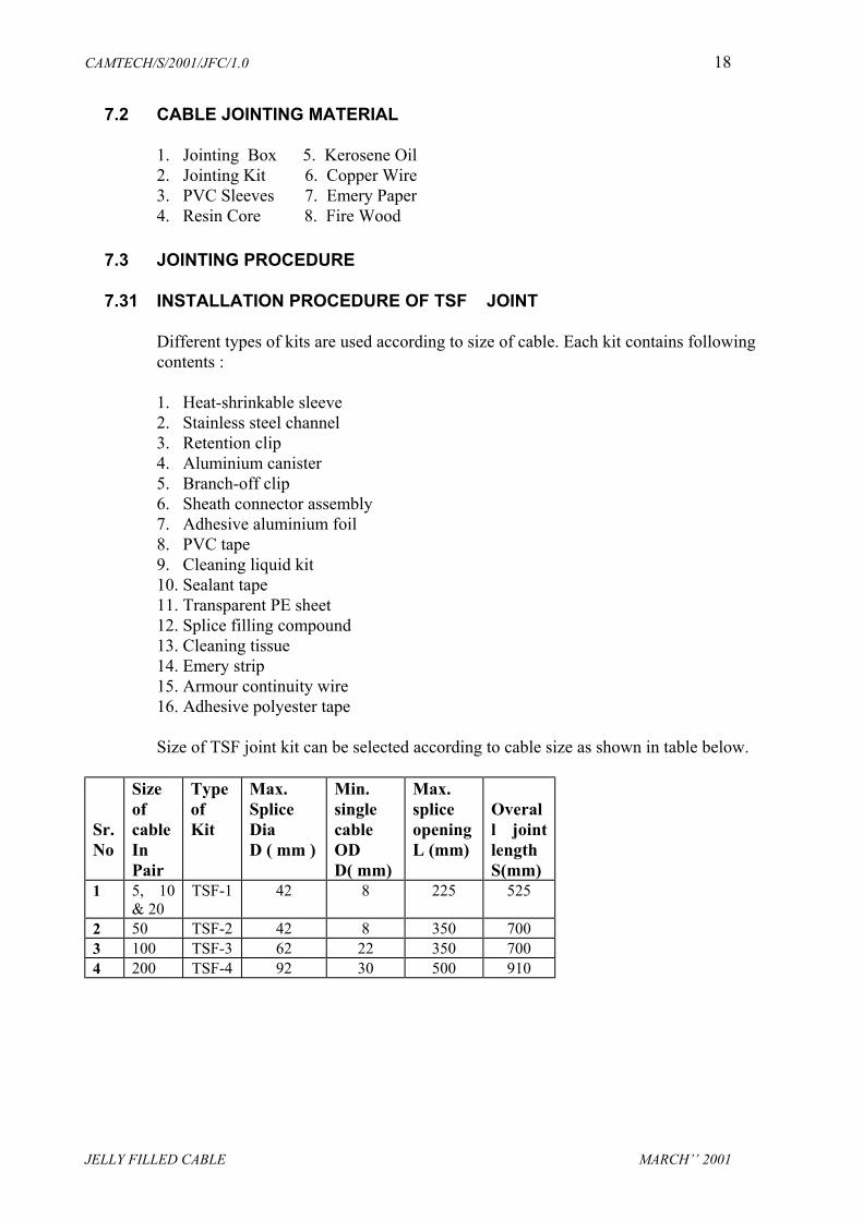
Size of TSF joint kit can be selected according to cable size as shown in table below.
Sr.No
SizeofcableInPair
TypeofKit
Max.SpliceDia D ( mm )
Min.singlecableODD( mm)
Max.spliceopeningL (mm)
Overall jointlengthS(mm)
1 5, 10& 20
TSF-1 42 8 225 525
2 50 TSF-2 42 8 350 7003 100 TSF-3 62 22 350 7004 200 TSF-4 92 30 500 910
CAMTECH/S/2001/JFC/1.0 19
JELLY FILLED CABLE MARCH’’ 2001
Cable Preparation
Dug a pit and erect a tent over it. Keep the cables to be jointed about 50 cm abovethe ground level. Select suitable size of kit according to size of cables.
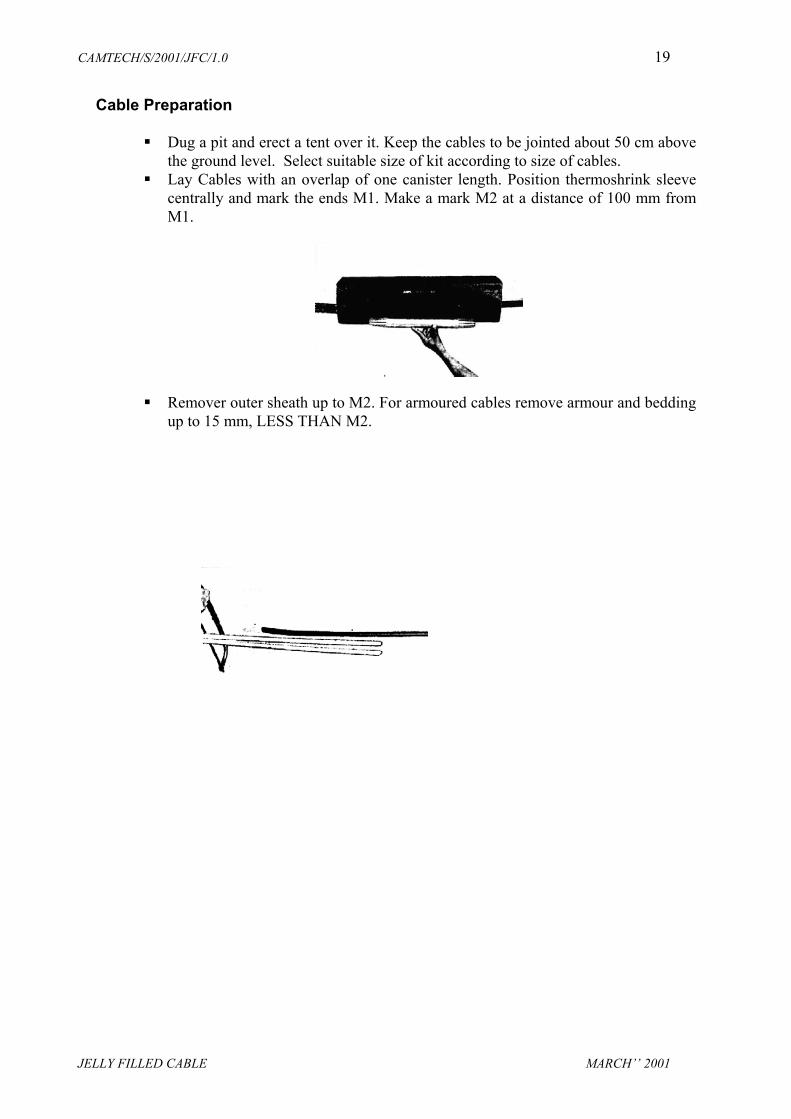
Lay Cables with an overlap of one canister length. Position thermoshrink sleevecentrally and mark the ends M1. Make a mark M2 at a distance of 100 mm fromM1.
Remover outer sheath up to M2. For armoured cables remove armour and beddingup to 15 mm, LESS THAN M2.
CAMTECH/S/2001/JFC/1.0 20
JELLY FILLED CABLE MARCH’’ 2001
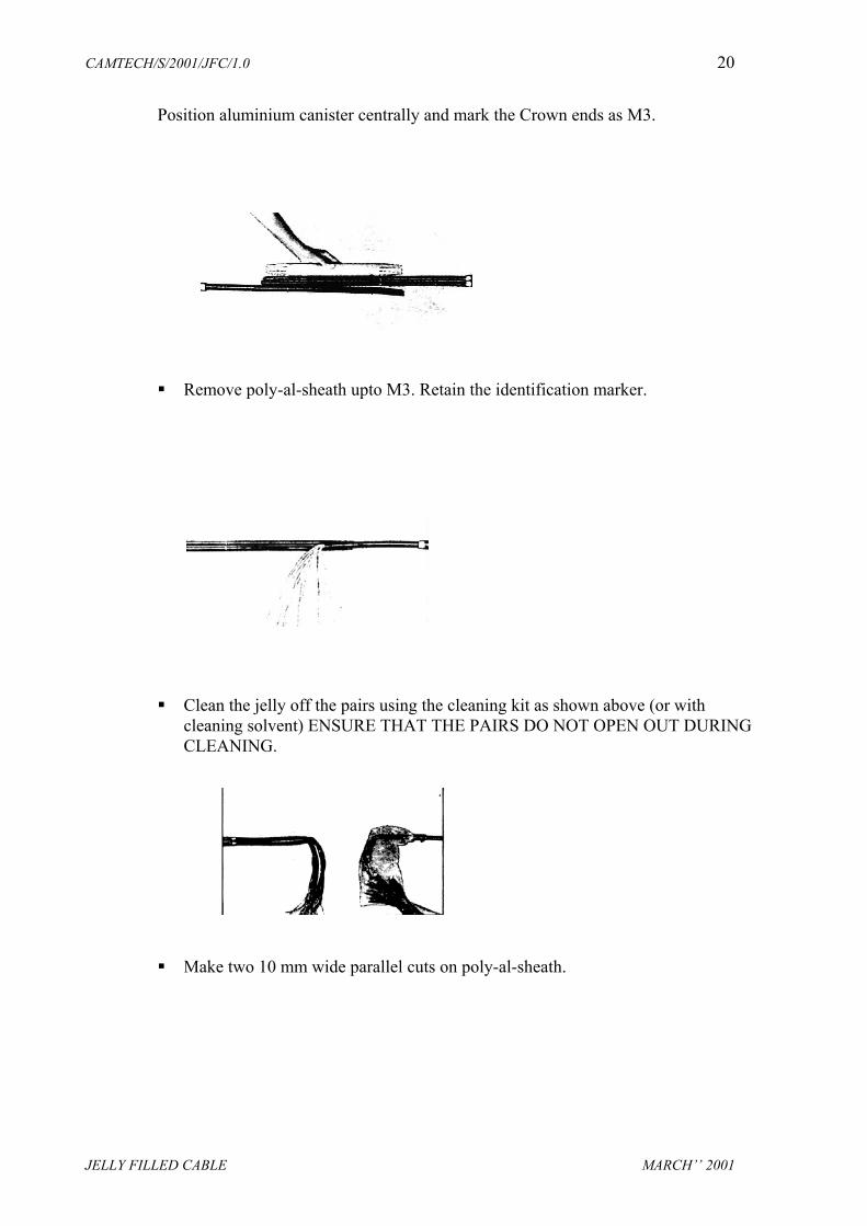
Position aluminium canister centrally and mark the Crown ends as M3.
Remove poly-al-sheath upto M3. Retain the identification marker.
Clean the jelly off the pairs using the cleaning kit as shown above (or withcleaning solvent) ENSURE THAT THE PAIRS DO NOT OPEN OUT DURINGCLEANING.
Make two 10 mm wide parallel cuts on poly-al-sheath.

CAMTECH/S/2001/JFC/1.0 21
JELLY FILLED CABLE MARCH’’ 2001
Crimp the main sheath connector to poly-al-sheath of either cable.
In branch joints, crimp the auxiliary sheath connector to the poly-al-sheath of thebranch cables. Interconnect the assembly using the bridge clip.

CAMTECH/S/2001/JFC/1.0 22
JELLY FILLED CABLE MARCH’’ 2001
Stretch and wrap sealant tape under and over the sheath connector clips.
Adjust the splice length by positioning the cannister.
CAMTECH/S/2001/JFC/1.0 23
JELLY FILLED CABLE MARCH’’ 2001
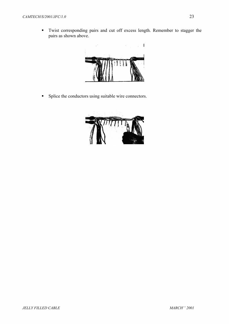
Twist corresponding pairs and cut off excess length. Remember to stagger thepairs as shown above.
Splice the conductors using suitable wire connectors.

CAMTECH/S/2001/JFC/1.0 24
JELLY FILLED CABLE MARCH’’ 2001
Splice bundle.
Affix transparent PE sheet on to the sealant tape and secure the ends with PVCtape.
CAMTECH/S/2001/JFC/1.0 25
JELLY FILLED CABLE MARCH’’ 2001
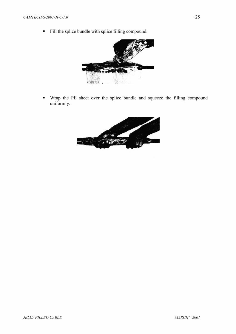
Fill the splice bundle with splice filling compound.
Wrap the PE sheet over the splice bundle and squeeze the filling compounduniformly.
CAMTECH/S/2001/JFC/1.0 26
JELLY FILLED CABLE MARCH’’ 2001
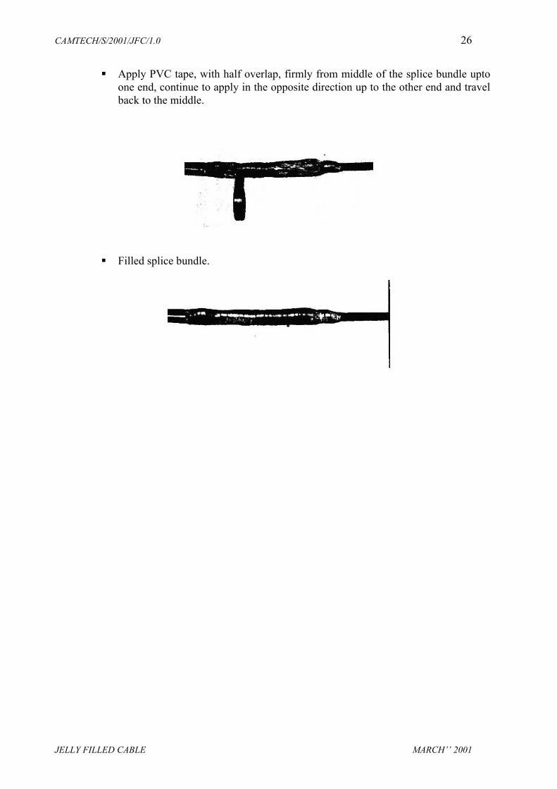
Apply PVC tape, with half overlap, firmly from middle of the splice bundle uptoone end, continue to apply in the opposite direction up to the other end and travelback to the middle.
Filled splice bundle.

CAMTECH/S/2001/JFC/1.0 27
JELLY FILLED CABLE MARCH’’ 2001
Install aluminium cannister around the splice bundle, such that the parting lines ofthe cannister are on the sides.
Apply one round of PVC tape in the middle to hold the cannister. Apply one layerof PVC tape on the cannister partition line. Apply two layers of PVC tape startingfrom the crown and ending a little beyond the cannister finger ends.

CAMTECH/S/2001/JFC/1.0 28
JELLY FILLED CABLE MARCH’’ 2001
Centre the thermoshrink sleeve and mark the ends. The surface between the endsof the cannister and this mark is bonding surface.
Clean the bonding surface with cleaning tissue. Don not touch the surface aftercleaning.
CAMTECH/S/2001/JFC/1.0 29
JELLY FILLED CABLE MARCH’’ 2001
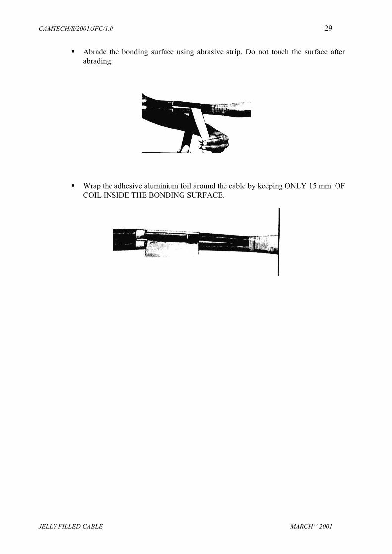
Abrade the bonding surface using abrasive strip. Do not touch the surface afterabrading.
Wrap the adhesive aluminium foil around the cable by keeping ONLY 15 mm OFCOIL INSIDE THE BONDING SURFACE.
CAMTECH/S/2001/JFC/1.0 30
JELLY FILLED CABLE MARCH’’ 2001
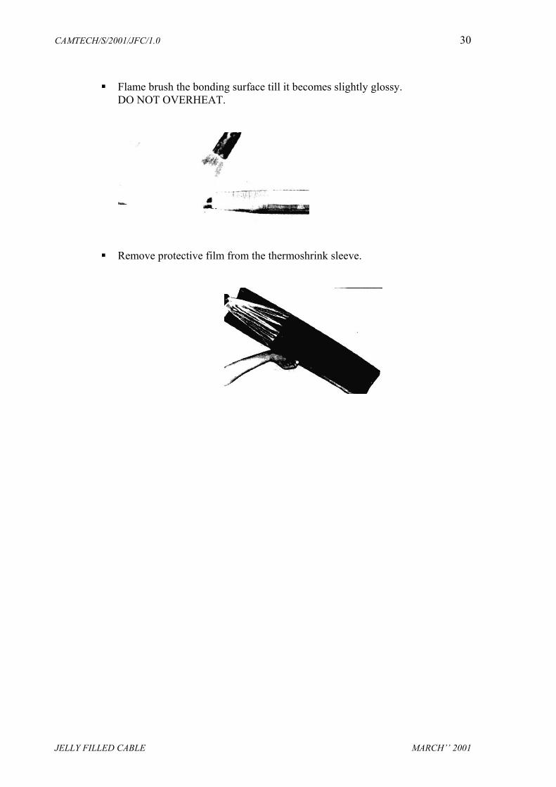
Flame brush the bonding surface till it becomes slightly glossy. DO NOT OVERHEAT.
Remove protective film from the thermoshrink sleeve.

CAMTECH/S/2001/JFC/1.0 31
JELLY FILLED CABLE MARCH’’ 2001
Position thermoshrink sleeve centrally and insert stainless steel channel(s) throughthe rails. Ensure that the channel(s) is/are on the top.
Insert channel retention clip over the channel joint, where two channels have beenused.
CAMTECH/S/2001/JFC/1.0 32
JELLY FILLED CABLE MARCH’’ 2001
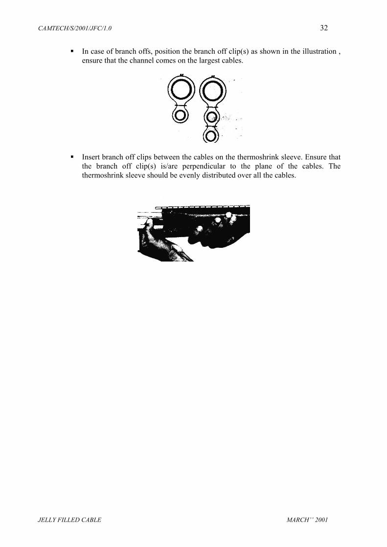
In case of branch offs, position the branch off clip(s) as shown in the illustration ,ensure that the channel comes on the largest cables.
Insert branch off clips between the cables on the thermoshrink sleeve. Ensure thatthe branch off clip(s) is/are perpendicular to the plane of the cables. Thethermoshrink sleeve should be evenly distributed over all the cables.

CAMTECH/S/2001/JFC/1.0 33
JELLY FILLED CABLE MARCH’’ 2001
Start thermoshrink from the middle to either side, in branch joints shrink the sidewit the lesser number of cables first.
Tap the channel gently at the transition points adjacent to the cannister crown.Thermoshrinking is complete when the thermochromic paint changes colour andthe adhesive oozes from the ends.
CAMTECH/S/2001/JFC/1.0 34
JELLY FILLED CABLE MARCH’’ 2001
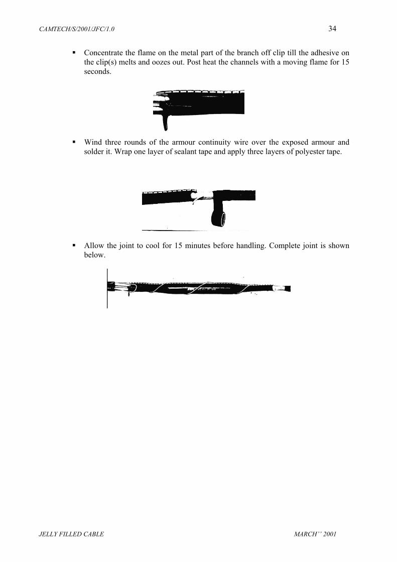
Concentrate the flame on the metal part of the branch off clip till the adhesive onthe clip(s) melts and oozes out. Post heat the channels with a moving flame for 15seconds.
Wind three rounds of the armour continuity wire over the exposed armour andsolder it. Wrap one layer of sealant tape and apply three layers of polyester tape.
Allow the joint to cool for 15 minutes before handling. Complete joint is shownbelow.

CAMTECH/S/2001/JFC/1.0 35
JELLY FILLED CABLE MARCH’’ 2001
7.4 JOINTING INSTRUCTIONS FOR QUADED JELLY FILLED CABLE
I) Mark M1 on both the cables at a distance of X from the cable end, where X is 425mm in case of straight through & condenser joint and 455mm in case of loading coil& transformer joint.
II) Cut and remove the outer sheath & armour upto M1, hence middle sheath is exposed.Mark 10mm on the outer sheath. Cut & remove outer sheath to expose the armour.
III) Mark M2 at the distance of Y from M1, on the middle sheath, where Y is 130mm incase of straight through & condensor joint and 170mm in case of loading coil &transformer joint. Cut and remove the middle sheath upto M2, hence Al shield wires are exposed.
IV) Mark 40 mm from M2 towards the cable end, on the aluminium shield wires. Cut andremove aluminium shield wires up to this mark, hence inner sheath is exposed.
V) Slide the split Al. ring over Al. Shield wires and bend back the wires over the ring.
VI) Lay cables with an overlap equal to exposed inner sheath (265mm). This will besplice length.
CAMTECH/S/2001/JFC/1.0 36
JELLY FILLED CABLE MARCH’’ 2001
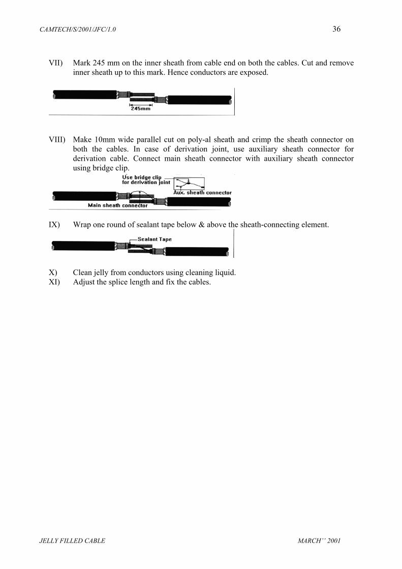
VII) Mark 245 mm on the inner sheath from cable end on both the cables. Cut and removeinner sheath up to this mark. Hence conductors are exposed.
VIII) Make 10mm wide parallel cut on poly-al sheath and crimp the sheath connector onboth the cables. In case of derivation joint, use auxiliary sheath connector forderivation cable. Connect main sheath connector with auxiliary sheath connectorusing bridge clip.
IX) Wrap one round of sealant tape below & above the sheath-connecting element.
X) Clean jelly from conductors using cleaning liquid.XI) Adjust the splice length and fix the cables.

CAMTECH/S/2001/JFC/1.0 37
JELLY FILLED CABLE MARCH’’ 2001
XII) Complete the splicing as per the conventional practice, without disturbing the splicebundle.
XIII) Fix TPE sheet using PVC tape around the splice bundle in such a way that pouch isformed.
XIV) Fill the filling compound in the pouch & cover it completely with TPE sheet. Squeezethe pouch to ensure that filling compound is evenly distributed and dia of splicebundle is uniform through out the splice. Keep sheath connector wire inside thepouch.
XV) Shrink heat shrinkable tube over the copper braid in such a way that braid is evenlyexposed at both ends. Fix the insulated copper braid with steel spring roll at both endsof the shield wire, over the aluminium rings.
CAMTECH/S/2001/JFC/1.0 38
JELLY FILLED CABLE MARCH’’ 2001
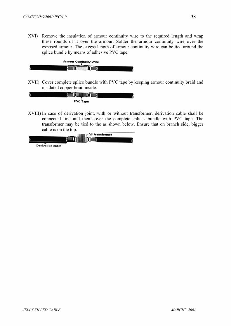
XVI) Remove the insulation of armour continuity wire to the required length and wrapthese rounds of it over the armour. Solder the armour continuity wire over theexposed armour. The excess length of armour continuity wire can be tied around thesplice bundle by means of adhesive PVC tape.
XVII) Cover complete splice bundle with PVC tape by keeping armour continuity braid andinsulated copper braid inside.
XVIII) In case of derivation joint, with or without transformer, derivation cable shall beconnected first and then cover the complete splices bundle with PVC tape. Thetransformer may be tied to the as shown below. Ensure that on branch side, biggercable is on the top.
CAMTECH/S/2001/JFC/1.0 39
JELLY FILLED CABLE MARCH’’ 2001
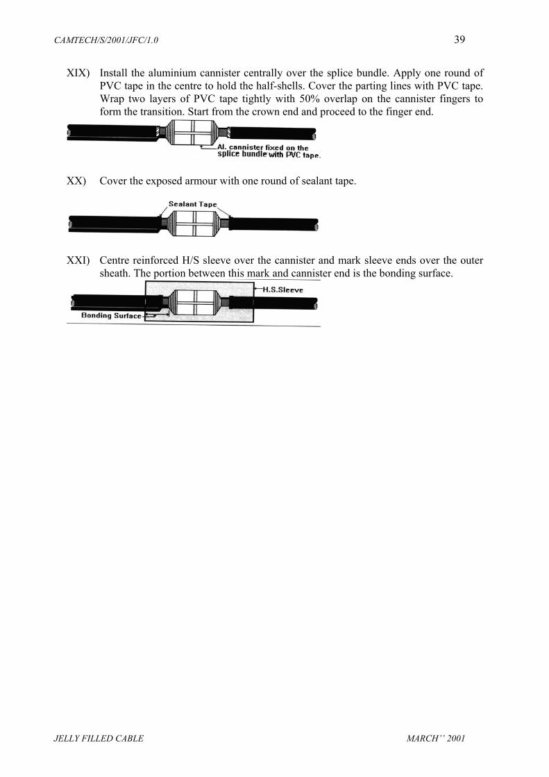
XIX) Install the aluminium cannister centrally over the splice bundle. Apply one round ofPVC tape in the centre to hold the half-shells. Cover the parting lines with PVC tape.Wrap two layers of PVC tape tightly with 50% overlap on the cannister fingers toform the transition. Start from the crown end and proceed to the finger end.
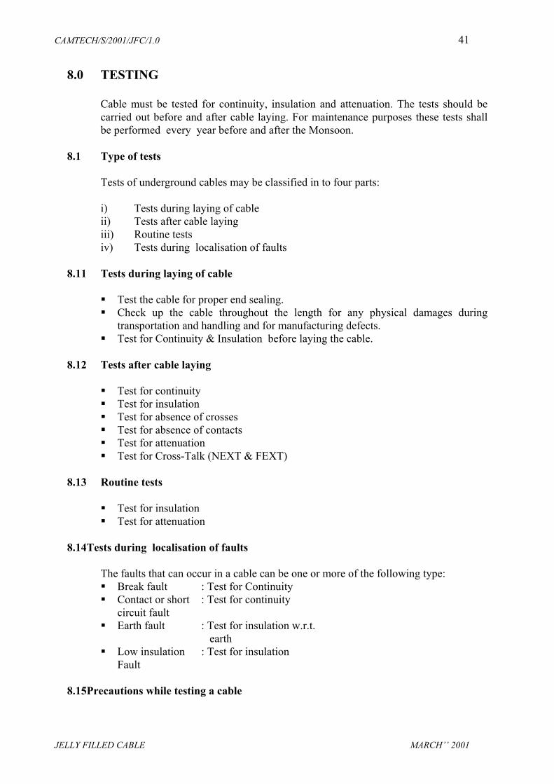
XX) Cover the exposed armour with one round of sealant tape.
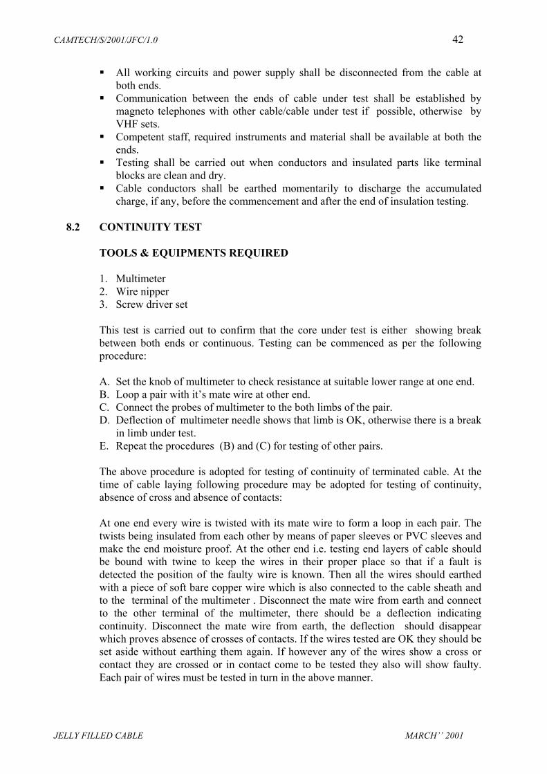
XXI) Centre reinforced H/S sleeve over the cannister and mark sleeve ends over the outersheath. The portion between this mark and cannister end is the bonding surface.

CAMTECH/S/2001/JFC/1.0 40
JELLY FILLED CABLE MARCH’’ 2001
XXII) Clean the bonding surface for grease and dirt with cleaning tissue. Do not touch thesurface after cleaning.
XXIII) Abrade the bonding surface circumferentially using emery strip. Do not touch surfaceafter abrading.
XXIV) Wrap one round of adhesive aluminium foil around the cable by keeping only 15mmof foil inside the bonding surface.
XXV) Flame brush the bonding surface till it become glossy. Do not overheat as it coulddamage the cable sheath.
XXVI) Wrap around the H.S.sleeve and position the under clip on sleeve rails at the centre.Slide S.S. channels over the rails in such a way that they meet at the centre of thesleeve and are held by the under clip. The channel portion of the sleeve shall beperpendicular to the cannister parting lines.
XXVII) In the case of derivation joints, insert the branch off clip on branch side as shown.Start shrinking the sleeve from centre and then proceed circumferentially to theeither ends. Tap the channel gently at the transition points adjacent to the cannistercrown. The shrinking is complete when thermocromic paint changes colour andwhite lines appear below the channels.
XXVIII) After shrinking do not disturb the joint for atleast 30 minutes.
CAMTECH/S/2001/JFC/1.0 41
JELLY FILLED CABLE MARCH’’ 2001
8.0 TESTING
Cable must be tested for continuity, insulation and attenuation. The tests should becarried out before and after cable laying. For maintenance purposes these tests shallbe performed every year before and after the Monsoon.
8.1 Type of tests
Tests of underground cables may be classified in to four parts:
i) Tests during laying of cableii) Tests after cable layingiii) Routine testsiv) Tests during localisation of faults
8.11 Tests during laying of cable
Test the cable for proper end sealing. Check up the cable throughout the length for any physical damages during
transportation and handling and for manufacturing defects. Test for Continuity & Insulation before laying the cable.
8.12 Tests after cable laying
Test for continuity Test for insulation Test for absence of crosses Test for absence of contacts Test for attenuation Test for Cross-Talk (NEXT & FEXT)
8.13 Routine tests
Test for insulation Test for attenuation
8.14 Tests during localisation of faults
The faults that can occur in a cable can be one or more of the following type: Break fault : Test for Continuity Contact or short : Test for continuity
circuit fault Earth fault : Test for insulation w.r.t.
earth Low insulation : Test for insulation
Fault
8.15 Precautions while testing a cable
CAMTECH/S/2001/JFC/1.0 42
JELLY FILLED CABLE MARCH’’ 2001
All working circuits and power supply shall be disconnected from the cable atboth ends.
Communication between the ends of cable under test shall be established bymagneto telephones with other cable/cable under test if possible, otherwise byVHF sets.
Competent staff, required instruments and material shall be available at both theends.
Testing shall be carried out when conductors and insulated parts like terminalblocks are clean and dry.
Cable conductors shall be earthed momentarily to discharge the accumulatedcharge, if any, before the commencement and after the end of insulation testing.
8.2 CONTINUITY TEST TOOLS & EQUIPMENTS REQUIRED
1. Multimeter 2. Wire nipper 3. Screw driver set
This test is carried out to confirm that the core under test is either showing breakbetween both ends or continuous. Testing can be commenced as per the followingprocedure:
A. Set the knob of multimeter to check resistance at suitable lower range at one end.B. Loop a pair with it’s mate wire at other end.C. Connect the probes of multimeter to the both limbs of the pair.D. Deflection of multimeter needle shows that limb is OK, otherwise there is a break
in limb under test.E. Repeat the procedures (B) and (C) for testing of other pairs.
The above procedure is adopted for testing of continuity of terminated cable. At thetime of cable laying following procedure may be adopted for testing of continuity,absence of cross and absence of contacts:
At one end every wire is twisted with its mate wire to form a loop in each pair. Thetwists being insulated from each other by means of paper sleeves or PVC sleeves andmake the end moisture proof. At the other end i.e. testing end layers of cable shouldbe bound with twine to keep the wires in their proper place so that if a fault isdetected the position of the faulty wire is known. Then all the wires should earthedwith a piece of soft bare copper wire which is also connected to the cable sheath andto the terminal of the multimeter . Disconnect the mate wire from earth and connectto the other terminal of the multimeter, there should be a deflection indicatingcontinuity. Disconnect the mate wire from earth, the deflection should disappearwhich proves absence of crosses of contacts. If the wires tested are OK they should beset aside without earthing them again. If however any of the wires show a cross orcontact they are crossed or in contact come to be tested they also will show faulty.Each pair of wires must be tested in turn in the above manner.
CAMTECH/S/2001/JFC/1.0 43
JELLY FILLED CABLE MARCH’’ 2001
8.3 INSULATION TEST TOOLS AND INSTRUMENTS REQUIRED 1. Insulation Tester (Megger) 500V DC 2. Wire nipper 3. Screw Driver set.
This test is carried out to measure the insulation resistance of the cable under test.Insulation resistance measured between (1) conductor to conductor and (2) conductorto earth. Procedure is as follows:
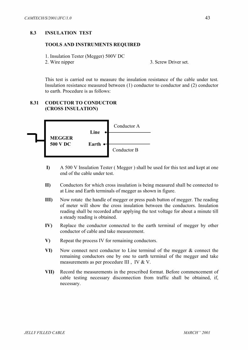
8.31 CODUCTOR TO CONDUCTOR (CROSS INSULATION) Conductor A
Line • MEGGER 500 V DC Earth • Conductor B
I) A 500 V Insulation Tester ( Megger ) shall be used for this test and kept at oneend of the cable under test.
II) Conductors for which cross insulation is being measured shall be connected to
at Line and Earth terminals of megger as shown in figure. III) Now rotate the handle of megger or press push button of megger. The reading
of meter will show the cross insulation between the conductors. Insulationreading shall be recorded after applying the test voltage for about a minute tilla steady reading is obtained.
IV) Replace the conductor connected to the earth terminal of megger by other
conductor of cable and take measurement. V) Repeat the process IV for remaining conductors. VI) Now connect next conductor to Line terminal of the megger & connect the
remaining conductors one by one to earth terminal of the megger and takemeasurements as per procedure III , IV & V.
VII) Record the measurements in the prescribed format. Before commencement of
cable testing necessary disconnection from traffic shall be obtained, if,necessary.

CAMTECH/S/2001/JFC/1.0 44
JELLY FILLED CABLE MARCH’’ 2001
8.32 CONDUCTOR TO EARTH INSULATION Conductor A Line • MEGGER 500 V DC Earth •
I) By this we can measure individual insulation of conductors w.r.t. earth. II) Connect conductor under test to the Line terminal of the megger. III) Connect earth terminal of the megger to the earth. IV) Rotate the handle of megger or press push button of megger. The reading of
meter will show the insulation resistance of the conductors. Insulation readingshall be recorded after applying the test voltage for about a minute till a steadyreading is obtained.
V) Replace the conductor at Line terminal of the megger by another conductorunder test and repeat as process IV.
The above measurements can be adopted for terminated cable. At the time of cablelaying following procedure can be used: To test a cable for insulation connect all the wires together at testing end with earthand sheath of the cable and also connect with earth terminal of meggar. Insulate allwires with each other at the other end of the cable. Remove one wire at testing endand connect with line terminal of the meggar. Now rotate the handle of meggar orpress the push button of meggar. The reading shall show the insulation resistance ofthe conductor with respect to earth and cross insulation w.r.t. other conductors. Similarly remove other conductors from bunch and connect on line terminal ofmeggar and measure insulation resistance of remain conductors. NOTE : 1. The value of insulation resistance shall not be less than 5000 mega ohms/km at
room temperature irrespective of the size of the conductor.2. During insulation test, meggaring should be done only for very short duration of
approximately one minute and conductor under test should be earthedmomentarily after meggaring to discharge the accumulated charge.
3. Insulation test should be done only by 100-Volt meggar during maintenance.
8.4 ATTENUATION TEST
Practically this test is conducted only for the underground jelly filled quaded cables,laid for special purposes in railway-electrified areas or non-electrified areas. In thistest 800 Hz tone of 0db is fed on one pair and measured at the other end on the samepair by using TMS kit or dB meter. The reading measured at far end shall give

CAMTECH/S/2001/JFC/1.0 45
JELLY FILLED CABLE MARCH’’ 2001
attenuation that can be converted into attenuation per kilometer. The averageattenuation of the pairs shall not exceed the value listed below at 200C :
The transmission loss in speech band i.e. 300-3400 Hertz and at no frquencyshould not be more than 2.5 dB/Km.
The transmission loss for PIJF telephone cable should not be more than 0.4dB/Km.
The transmission loss for quaded jelly filled cable (Loaded) should not be morethan 0.4 dB/Km.
The transmission loss for quaded jelly filled cable (Unloaded) should not be morethan 2.5 dB/Km.
8.5 Loop Resistance
The loop resistance of conductors and the tolerance on the individual values are givenin table below:
Diameter ofConductorin mm
Resistance perkm. At 200 C
ToleranceOhms/Km.
0.50 mm 172 Ohm + 6
0.63 mm 116 Ohm + 4
0.90 mm 56 Ohm + 2
8.6 CROSS TALK TEST
The signals of one pair of the cable produces unwanted signals in other pairs due toelectrostatic and magnetic inductive effects. These unwanted signals called CrossTalk. The first pair is called disturbing pair and other pair called disturbed pair. The Cross Talk is depend on line length, transposition scheme used /Polling, thefrequencies involved and the level differences on the particular pairs. The cross talk can be either Near end cross talk (NEXT).or Far end cross talk (FEXT)or both.
CAMTECH/S/2001/JFC/1.0 46
JELLY FILLED CABLE MARCH’’ 2001
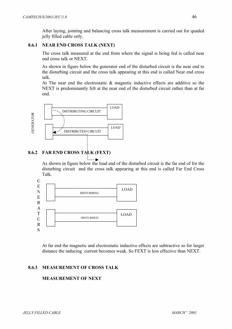
After laying, jointing and balancing cross talk measurement is carried out for quadedjelly filled cable only.
8.6.1 NEAR END CROSS TALK (NEXT)
The cross talk measured at the end from where the signal is being fed is called nearend cross talk or NEXT. As shown in figure below the generator end of the disturbed circuit is the near end tothe disturbing circuit and the cross talk appearing at this end is called Near end crosstalk. At The near end the electrostatic & magnetic inductive effects are additive so theNEXT is predominantly felt at the near end of the disturbed circuit rather than at farend.
DISTRIBUTING CIRCUITLOAD
DISTRIBUTED CIRCUITLOAD
GEN
ERA
TOR
8.6.2 FAR END CROSS TALK (FEXT)
As shown in figure below the load end of the disturbed circuit is the far end of for thedisturbing circuit and the cross talk appearing at this end is called Far End CrossTalk. At far end the magnetic and electrostatic inductive effects are subtractive so for largerdistance the inducing current becomes weak. So FEXT is less effective than NEXT.
8.6.3 MEASUREMENT OF CROSS TALK MEASUREMENT OF NEXT
GENERATORS
LOAD
LOADDISTURBING
DISTURBED

CAMTECH/S/2001/JFC/1.0 47
JELLY FILLED CABLE
1. Terminate the far ends of the cable pairs with it’s characteristic impedance i.e.1120 ohms.
2. Fed an audio tone of 800 Hz, 0dB on one pair of the cable with the help of aTMS kit/Oscillator.
3. Measure the cross talk level on other pairs at feeding end with the help of a dBmeter, as shown below.
DISTURBING CIRCUIT
MEASUREMENT OF FEXT
1. Terminate the far ends of the cable pair on which the tone is being fed and thenear of that cable pairs on which the cross talk level is being measured withit’s characteristic impedance i.e. 1120 ohms.
2. Fed an audio tone of 800 Hz, 0dB on one pair of the cable with the help of aTMS kit/Oscillator.
3. Measure the cross talk level on other pairs at far end with the help of a dBmeter, as shown below.
DISTURBING CIRCUIT DISTURBED CIRCUIT Let us assumes that on feeding a tone of 800 Hz level on other pair is –70 dBm. It means the cross tthese pairs. If this value is more it shows better perf RECOMMENDED CROSS TALK LEVEL
NEXT : Better than –61 dB FEXT : Better then –65 dB
800 Hz0 dB
DBMETER
1120ohms
1120ohms
800 Hz0 dB
dBMeter
1120Ohms
1120ohms
MARCH’’ 2001
0 dBm one pair and measured thealk is attenuated to 70 dB betweenormance of the circuit.

CAMTECH/S/2001/JFC/1.0 48
JELLY FILLED CABLE MARCH’’ 2001
8.6.4 PRECAUTIONS 1. Before measurement the pair should be terminated with characteristic
impedance. 2. The instruments shall be connected very near to to the cable i.e. avoid long
wiring connections.3. Phantom circuits, if any shall be disconnected before measurements. 4. The line staff should not be allowed to disturb the line during testing.
8.7 After completion of cable testing:
• Ensure that all conductors have been reconnected properly. • Test the functions of all equipments connected through the cable for their correct
response. • Check whether any polarity of any feed taken through the cable has got earthed
inadvertently.
9.0 MAINTENANCE
9.1 ROUTINE TESTS
Underground jelly filled cables shall be tested once in every year preferably beforemonsoon with a meggar for insulation only and the results of tests shall be submitted toDSTE/ASTE.
Apart from the testing performed during laying and after laying the cables, routine testsshall also be conducted on the cables to ensure that the cable is in good condition. Thiswill provide data to decide as to when a cable has served its life and to replace the samein time, to avoid complete breakdown.
All spare pairs in a cable shall be tested periodically once in a year to ensure that they arein good condition. This will help in using the same pairs whenever a working pair hasbeen faulty and the circuit carried by it has to be transferred to one of the spare pair.
9.2 MAINTENANCE
Underground cable installations when laid strictly in accordance with the recommendedpractice will hardly need any maintenance throughout their anticipated span of life. As faras the buried portion of the cable is concerned, no repairs are generally possible except incases where moisture or water has entered the cable and is detected before it has damagedthe insulation.
All cable termination devices, pillar boxes, cable heads and glands shall be kept clean anddry.
These parts shall be frequently inspected and any tendency for moisture or water leakshall be immediately attended too.
Where humidity is high, particular care shall be taken regarding the condition of the cableheads. Pillar boxes, etc, and those may be dried by charcoal fore or anhydrous gas as andwhen required, taking necessary precautions against fire hazards.

CAMTECH/S/2001/JFC/1.0 49
JELLY FILLED CABLE MARCH’’ 2001
All cables shall be tested periodically to enable timely action being taken and preventbreakdowns.
No digging operation by other department shall be allowed close to the cable routewithout prior notice to the telecommunication Inspector who will take necessaryprecautions to protect the cable from damage.
As a preventive measure, cable route should be periodically inspected to detect anydigging work going on the cable route or already dugged in past. This will be very helpfulto prevent the cable for being damaged if digging work is going on or to localise the faultin the cable if route has been dugged in past.