jeffrey d. nickeljeffrey d. nickel · the system chosen for this analysis was the 1998 buell®...
TRANSCRIPT

1
A Study of RiderA Study of RiderA Study of RiderA Study of Rider Posture and ControlsPosture and ControlsPosture and ControlsPosture and Controls
Human FactorsHuman FactorsHuman FactorsHuman Factors
Engineering Analysis, Engineering Analysis, Engineering Analysis, Engineering Analysis,
1998 Buell® S3T®, 1998 Buell® S3T®, 1998 Buell® S3T®, 1998 Buell® S3T®,
Thunderbolt® TouringThunderbolt® TouringThunderbolt® TouringThunderbolt® Touring
Presented by:Presented by:Presented by:Presented by:
Jeffrey D. NickelJeffrey D. NickelJeffrey D. NickelJeffrey D. Nickel
MSF Certified Instructor, MSF Certified Instructor, MSF Certified Instructor, MSF Certified Instructor, Maryland Motorcycle Safety ProgramMaryland Motorcycle Safety ProgramMaryland Motorcycle Safety ProgramMaryland Motorcycle Safety Program
Human Human Human Human Factors Research EngineerFactors Research EngineerFactors Research EngineerFactors Research Engineer
Virginia Polytechnic Institute, Industrial and Virginia Polytechnic Institute, Industrial and Virginia Polytechnic Institute, Industrial and Virginia Polytechnic Institute, Industrial and Systems Engineering Systems Engineering Systems Engineering Systems Engineering ---- Graduate Student Graduate Student Graduate Student Graduate Student
March 2001March 2001March 2001March 2001

2
Table of Contents
Table of Contents 2
Thanks 2 System Description 2
Usability & Error Analysis 2 Donald Norman's Approach 4
Link Analysis 5
Function Allocation 7
Summary and Conclusions 8 Figures 9 Usability Survey 11
Thanks to Those Who Helped
This study was not sponsored, or endorsed by Buell® American Motorcycles, Harley-Davidson® Motorcycles, the Harley-Davidson® Store of Baltimore, or the Motorcycle Safety Foundation. Observations and findings presented within this document shall not be construed as those of any of the afore-mentioned organizations. The use of the organization names is only for information purposes and does not constitute their agreement with the views presented within. I wish to thank the management and staff of the Harley-Davidson® Store of Baltimore for allowing this opportunity to survey their patrons and employees and deeply appreciate the time offered by all those who volunteered to participate in this study.
System Description The system chosen for this analysis was the 1998 Buell® Thunderbolt® S3T®. This is a
sport touring motorcycle with a 1203cc Harley-Davidson® motor built to Buell® specifications that produces over 100 hp, known as the Thunderstorm™. Observations will include a comparison to the 1999 model. Some changes were a new frame, fuel injection, suppliers and cosmetic improvements. The S3T® differs from the S3® with the addition of fairing lowers, saddlebags, fairing bags and higher, narrower handlebars.
Usability & Error Analysis
Usability is a very general term among design engineers, marketing professionals and legal departments. For this report I am defining usability in a basic anthropometric genre. The controls and displays are considered usable if they can be reached and activated or viewed as needed. Degree of difficulty was also recorded. Functions that are humanly possible but required extreme, awkward, uncomfortable or unsafe contortions to accomplish are noted. The participants were questioned and observed individuals as they attempted to identify or locate the

3
controls and displays while properly seated on the subject motorcycle. A special set of stands to securely restrain the motorcycle were manufactured by the Harley Davidson® Store of Baltimore and loaned to me for the duration of the study. To collect this data, I set up the subject bike in front of the Harley-Davidson® Store of Baltimore and in front of my office building. This allowed me survey a group of motorcycle riders with their prejudices and experiences using controls and displays while riding, and a group of non riders who would simply report on how the locations feel and if they can easily operate the controls. During this survey I was also able to observe errors like using the wrong control or not being able to find the correct one. My observations are noted later in this report. I read the survey and recorded the responses to be sure the intent of the question was understood and the response scale was consistent. This also assured that the survey itself did not interfere with the operation of the controls or the view of the displays. Of the twenty-seven participants in this portion of the study, nine were non-riders, eight were Buell® riders, and four were riders of other sport bikes. The participants rankings of the issues were fairly consistent in the range of agree to strongly agree. Though some of the non-rider participants needed direction with the location of some controls, the area in which the most participants desired change was in the addition of some displays. Specifically a desire for the addition of an oil pressure and or oil temperature gage, a fuel gage and a gear indicator. The gear indicator request came from two participants who not only were non-riders but also have no experience with a manual transmission. Some participants with smaller hands wanted a shorter throw and easier pull for the handlebar levers. In bright sunlight some participants expressed a desire for brighter indicator lights. Most participants desired a relocation of the horn button, currently relatively low, under the left thumb, and can be awkward to use. The error analysis was performed in conjunction with the usability survey and through anecdotal references. No models or predictions were made. The most common error was for the rider to push the starter button when wanting to activate the right turn indicator. This was because most of the experienced participants were Harley® riders and assumed the system of split signal actuators. Canceling the turn indicators was over-looked at times but is not truly an error in identification, location and function of controls. Among the non-riders fewer errors were made. This may be due to their greater concern for performance in a new environment not that they had a better understanding of the tasks. The error could cause damage to the starter system and therefore should be avoided. A suggested fix would be to electronically constrain the system so that the starter can not be engaged if the engine is running. The only other error observed was when participants tried to shift into neutral. Going from first to neutral was more difficult than from second to neutral. I attribute this variance to the fact that pushing down with the ball of ones foot is a more natural action and can be done with greater control than pulling up with ones toes. The transmission was warm and the bike parked on the level therefore blame cannot be placed on the transmission. It is understood that a harder detent for neutral, like those for the selections could cause greater errors by shifting into neutral instead of first or second. The indicator light is in a good location and is bright enough to let the rider know if they have acquired the neutral position but an easier way to get there would be appreciated by all those I talked with. The one down, four up pattern caused no trouble. Another error of omission was not being able to locate the flash to pass button. This occurred because it is not a common feature and once learned it was found easily and appreciated by almost everyone; others had no comment on the feature.
4
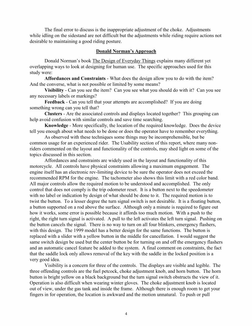
The final error to discuss is the inappropriate adjustment of the choke. Adjustments while idling on the sidestand are not difficult but the adjustments while riding require actions not desirable to maintaining a good riding posture.
Donald Norman’s Approach Donald Norman’s book The Design of Everyday Things explains many different yet overlapping ways to look at designing for human use. The specific approaches used for this study were: Affordances and Constraints - What does the design allow you to do with the item? And the converse, what is not possible or limited by some means? Visibility - Can you see the item? Can you see what you should do with it? Can you see any necessary labels or markings? Feedback - Can you tell that your attempts are accomplished? If you are doing something wrong can you tell that? Clusters - Are the associated controls and displays located together? This grouping can help avoid confusion with similar controls and save time searching. Knowledge - More specifically, the location of the required knowledge. Does the device tell you enough about what needs to be done or does the operator have to remember everything. As observed with these techniques some things may be incomprehensible, but be common usage for an experienced rider. The Usability section of this report, where many non-riders commented on the layout and functionality of the controls, may shed light on some of the topics discussed in this section. Affordances and constraints are widely used in the layout and functionality of this motorcycle. All controls have physical constraints allowing a maximum engagement. The engine itself has an electronic rev-limiting device to be sure the operator does not exceed the recommended RPM for the engine. The tachometer also shows this limit with a red color band. All major controls allow the required motion to be understood and accomplished. The only control that does not comply is the trip odometer reset. It is a button next to the speedometer with no label or indication by design of what should be done to it. The required motion is to twist the button. To a lesser degree the turn signal switch is not desirable. It is a floating button, a button supported on a rod above the surface. Although only a minute is required to figure out how it works, some error is possible because it affords too much motion. With a push to the right, the right turn signal is activated. A pull to the left activates the left turn signal. Pushing on the button cancels the signal. There is no way to turn on all four blinkers, emergency flashers, with this design. The 1999 model has a better design for the same functions. The button is replaced with a slider with a yellow button in the middle for cancellation. I would suggest the same switch design be used but the center button be for turning on and off the emergency flashers and an automatic cancel feature be added to the system. A final comment on constraints, the fact that the saddle lock only allows removal of the key with the saddle in the locked position is a very good idea. Visibility is a concern for three of the controls. The displays are visible and legible. The three offending controls are the fuel petcock, choke adjustment knob, and horn button. The horn button is bright yellow on a black background but the turn signal switch obstructs the view of it. Operation is also difficult when wearing winter gloves. The choke adjustment knob is located out of view, under the gas tank and inside the frame. Although there is enough room to get your fingers in for operation, the location is awkward and the motion unnatural. To push or pull

5
perpendicular to the bike is not easy. It is made even harder when the motion must be precise and the knob is stiff to avoid unwanted slippage in the control. The fuel petcock is completely hidden well up under the gas tank and partially concealed by a frame member. This is a control that doesn’t give any warning for needing to be used. It’s function is turn the gas flow on or off, or, to switch to the reserve gas when the tank is getting low. This is needed as the engine sputters from lack of gas. The rider reaches down between their legs, under the gas tank, between the frame rails and to the petcock. The actuation motion is to rotate the lever down and forward. The motion is not hard but is more difficult than it be. Feedback is very good throughout the motorcycle. Whether it is throttle response or fuel flow, gear selection or brake application, the rider feels an immediate and appropriate feedback. No complaints or problems were observed.
Clusters appear to be very good also. The engine shut-off switch and start buttons are together. The high/low beam selector, flash to pass, turn signals and horn button are all together. As with feedback, no problems were found.
Knowledge has a few sticky points. As mentioned with the trip odometer reset button, a label would have been nice. The fuel petcock is hard to read but if used often enough the rider will learn to feel the position and understand how it is set. The complete loss of knowledge, not in the user or the motorcycle is how to release the saddle to access the under seat storage, helmet hooks and oil tank. When first attempting this, I was told to reach under the tail section and twist the lock by hand. I did this twice then thought the engineers weren’t that dumb. They weren’t. A pull knob with a cable actuator is attached to the lock. This, though hard to find at first, works well. A small label on the body to indicate the position of this release is recommended.
Link Analysis
A Link Analysis is used to determine if a possible series of events such as, viewing displays, adjusting controls or movements that could be effected by the layout could be rearranged to increase the efficiency or safety of the overall operation. Considering safety, the “fly on the windshield” technique would be difficult. Therefore, I timed myself, using the sweep second hand on the bike, for the scans I considered. See Figure 1 for the dash layout and position of the clock. Functioning as the data collector and subject may cause a loss of some data, but the scenario provides the required elements. Times were rounded to the second and collected on a warm bike, therefore scanning the tachometer while adjusting the choke was not included.
Information gathered in the Usability and Error Analysis portions made the selection of appropriate scans easier and provided a basis for what to look for during the scans. Further more, what design changes to suggest and/or the rationale for not making extensive changes to the current layout.
Focusing on the eye scan pattern between visual displays, the road ahead and mirrors while driving would require isolating these functions in a real world situation. Figure 1 shows the S3T® display layout. To do this I considered the display and mirror scanning pattern used for driving on a familiar interstate highway, in light to moderate traffic, at conservative speeds (70-75 mph), to avoid confusion with other operations. Depending on lane position and which lane was being used, the scan would go from the more appropriate side mirror, to the speedometer, to the lesser mirror and back to the front. Except for the occasions when rechecking was required, this entire scan took 3 to 4 seconds. These scans would occur about every 15 to 30 seconds depending on traffic and intended movements between lanes. When the turn signal was used a scan of the turn signal indicator display on the dash for verification was

6
added to the scan but this added no noticeable time because the display is located within the normal eye sweep.
The position of both of the mirrors and all displays is forward, central and nearly on the same horizon, a scanning view of all items is smooth, quick and easily accomplished with limited loss of driving view. The displays and mirrors are located far enough forward to not require refocus between the various elements and the road ahead. At cruising speeds, the bike would travel 140 to 190 feet during a scan. The operators forward view is never obstructed and remains active even though not primary or centered. The scan only requires eye motion, not head motions. This is much safer than in a car where head motion is usually required to visit all the mirrors and displays. The lost time of a frontal driving view has been the blame of many crashes over the years.
Focusing on the hand and foot motions would be more meaningful during a pleasure ride on smaller roadways. This would involve using the brakes, clutch, gear selector, turn signals and most of the displays offered on the dashboard. Refer to Figure 1 for the dashboard displays and hand controls. As the motorcycle approaches a stop sign, where a right turn is intended, the rider has a few things to do. Depending on speed and current gear selection the timing of these events may vary but they must all be done. For this narrative we will assume the motorcycle is moving about 40 mph in 4th gear. As the approach begins, the rider rolls the throttle, a right hand action, forward to reduce engine speed. The right fingers stretch forward from the grip to curl over and pull in the front brake lever gently. At the same time the right foot is depressing the rear brake lever, a natural motion if the lever has been adjusted correctly. In a simultaneous operation, the left fingers should be outstretched to pull in on the clutch lever and disengage the clutch for down shifting. After the engine and transmission are completely disengaged, the left foot presses down on the gear selection lever and releases after feeling the selector reach the detent. This is followed by shifting though the remaining gears by holding in the clutch lever and repeatedly tapping down the gear selector lever until the operator reaches first gear.
At some point in the braking and shifting process the turn signal should be activated. This is a push with the left thumb. This operation can be cumbersome if heavy gloves are worn and the attempt is made while holding in the clutch. No errors occurred but some difficulty was observed. The design of the 1999 model eases this problem but does not eliminate it.
Selecting a “link” between the components is difficult for a scan process that occurs in a few seconds, includes 5 to 7 items, and/or a control manipulation process where the time window is small and there don’t appear to be any conflicts in the layout. The current arrangement of controls is based on industry standards. Certain minor changes do exist in the “feel” or reaction to the control. The displays are not governed this way. The mirrors are governed by federal safety requirements. This is where the S3 really shines. Though it is not perfect, in that many people would prefer more displays, those that are included are adequate and in a very good layout. Few bikes can match the forward view of the mirrors or the instrument pod. As for a redesign of the layout, only one to include more displays would improve the layout. This does not mean it is perfect. Larger, flatter mirrors would reduce the time needed to absorb the information. Some of the controls were adjusted to fit rider preferences.
My suggested redesign based on participant comments and personal experience includes the addition of an oil temperature and pressure gage in the instrument pod. Figure 3 represents the basic concept of my proposal. They would be combined in one unit the size of the clock and adjusted so normal operating conditions would be displayed with the needles both vertical, one up and one down. Zero or low would be left of center. Redesign would not effect the data in this
7
link analysis. This change also eases the operator’s allocation of functions in their task of adjusting the choke. The operator would read the gages rather than “idle” the engine while riding, making the cold start routine easier. This knowledge is not only a humans desire but important in a parade or long traffic jam. Air-cooled engines are at risk in these conditions. During open running on the road, loss of oil pressure can be deadly, to bike and operator. The gage gives a better idea of engine status than the current indicator light. The change is clean in presentation and simple in layout.
Function Allocation
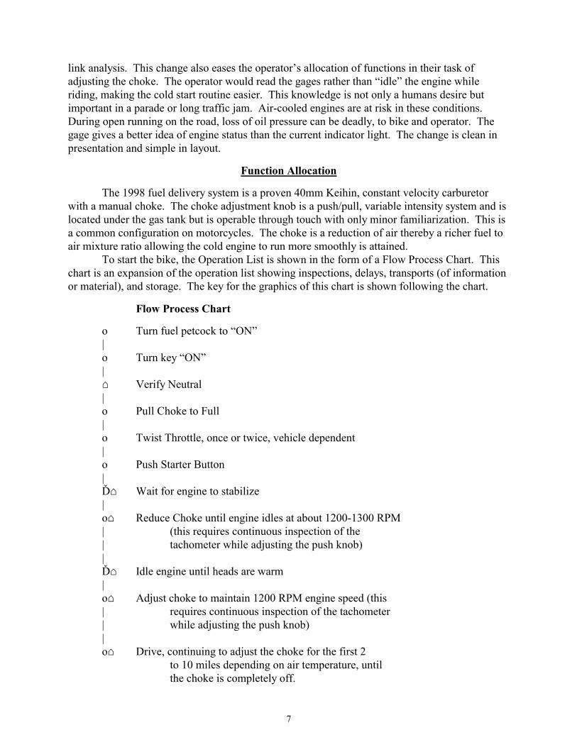
The 1998 fuel delivery system is a proven 40mm Keihin, constant velocity carburetor with a manual choke. The choke adjustment knob is a push/pull, variable intensity system and is located under the gas tank but is operable through touch with only minor familiarization. This is a common configuration on motorcycles. The choke is a reduction of air thereby a richer fuel to air mixture ratio allowing the cold engine to run more smoothly is attained.
To start the bike, the Operation List is shown in the form of a Flow Process Chart. This chart is an expansion of the operation list showing inspections, delays, transports (of information or material), and storage. The key for the graphics of this chart is shown following the chart.
Flow Process Chart о Turn fuel petcock to “ON”
| о Turn key “ON”
| ⌂ Verify Neutral
| о Pull Choke to Full
| о Twist Throttle, once or twice, vehicle dependent
| о Push Starter Button
| Ď⌂ Wait for engine to stabilize |
о⌂ Reduce Choke until engine idles at about 1200-1300 RPM | (this requires continuous inspection of the | tachometer while adjusting the push knob)
| Ď⌂ Idle engine until heads are warm
| о⌂ Adjust choke to maintain 1200 RPM engine speed (this | requires continuous inspection of the tachometer | while adjusting the push knob)
| о⌂ Drive, continuing to adjust the choke for the first 2 to 10 miles depending on air temperature, until the choke is completely off.

8
Summary of Flow Process Chart: Number of Operations 8 plus Number of Delays 2 Number of Inspections 4 plus Chart Graphics Key: Operation: о Delay: Ď
Inspection: ⌂
The rationale for the allocation of functions for the 1998 is simple. Or, I should say simplicity. The mechanical and electronic simplicity of a manual system is easy to design, build and maintain. Though use of a system like this may not be as easy for the operator, this system has been in large scale use for decades and is considered the standard system for motorcycles and other smaller engines. In years past the technology for the required sensors and processors which would replace the perception and cognition of the human operator was either too expensive or too bulky for a lightweight sport bike. This situation has changed, for the good.
Adjusting the choke requires frequent idling of the engine, while riding, to determine if the fuel/air mixture was correct. Pulling in the clutch and releasing the throttle accomplishes this. During this time the bike slows, creating a speed mismatch between the engine and road. The suspension is unloaded and the operator’s attention is diverted to the tachometer. Another difficulty then arises when the choke needs adjustment. It is located on the left side of the engine. The left hand, which is holding in the clutch, also adjusts the choke. This means the operator must throttle up to speed, adjust the choke and repeat the idle inspection procedure. If the rider ran the engine too lean it would stall at idle. If the engine were over choked it would run fast during idle, waste gas and sputter or loose power at higher RPM. A rich fuel/air ratio also fouls the spark plugs, decreasing performance and efficiency. Although fuel usage is not a concern for a sport bike rider, lost performance is not acceptable.
Summary and Conclusions
The Link Analysis was not as useful in this study as the Function Analysis. The times involved were short and no apparent conflicts. Figure 7 shows the worst located controls, the fuel petcock and choke knob. They are positioned under the gas tank and inside the frame. Though the choke is reachable and the location can be learned, the fuel petcock is hidden further under the bodywork and behind the riders knee to where the knee must be moved away to complete the task. Both controls are no longer included on 1999 and newer models because the DDFI handles these functions electronically. In conclusion the 1998 Buell® was a fine design. The 1999 model includes improvements. One additional improvement observed on the 1999 is that of the engine shut-off switch. The old design was a rocker switch that was rocked back to shut-off the engine. The new design is the same type of control and location but the action is reversed so that the rocking is in the same direction as the rolling off of the throttle. This may not have been a problem because few riders use the engine shut-off switch, however it is an human factors improvement.

9
Figure 1: 1998 Buell® S3T™ Dash and Handlebar Controls
Figure 2: 1998 Buell® S3T™, Left Hand Controls

10
Figure 3: Proposed New Dash Gage Layout
Figure 4: Choke and fuel petcock on 1998 Buell® S3T™ References: Norman, Donald A. (1990). The Design of Everyday Things; Currency-Doubleday. Wilson, John R. and Corlett, E. Nigel, editors (1995). Evaluation of Human Work, 2nd edition; Taylor and Francis.

11
Usability Survey Do you ride a Buell® ? YES ____ NO ____ Do you ride a motorcycle? YES ____ NO ____ What Make / Model? _________________________________ The gages are easily read? (brightness & contrast) |________|________|________|________|________|________|________| strongly agree slightly neutral slightly disagree strongly agree agree disagree disagree The gages are easily understood? (confusion over meaning) |________|________|________|________|________|________|________| strongly agree slightly neutral slightly disagree strongly agree agree disagree disagree Enough gages are present? |________|________|________|________|________|________|________| strongly agree slightly neutral slightly disagree strongly agree agree disagree disagree The indicator lights are easily read? |________|________|________|________|________|________|________| strongly agree slightly neutral slightly disagree strongly agree agree disagree disagree The indicator lights are easily understood? |________|________|________|________|________|________|________| strongly agree slightly neutral slightly disagree strongly agree agree disagree disagree Enough indicator lights are present? |________|________|________|________|________|________|________| strongly agree slightly neutral slightly disagree strongly agree agree disagree disagree Turn signal switches located well? (to reach and use correctly) |________|________|________|________|________|________|________| strongly agree slightly neutral slightly disagree strongly agree agree disagree disagree Horn switch located well? (to reach and use correctly) |________|________|________|________|________|________|________| strongly agree slightly neutral slightly disagree strongly agree agree disagree disagree
12
Start switch located well? (to reach and use correctly) |________|________|________|________|________|________|________| strongly agree slightly neutral slightly disagree strongly agree agree disagree disagree Shut-off switch located well? (to reach and use correctly) |________|________|________|________|________|________|________| strongly agree slightly neutral slightly disagree strongly agree agree disagree disagree
Flash to Pass switch located well? (to reach and use correctly) |________|________|________|________|________|________|________| strongly agree slightly neutral slightly disagree strongly agree agree disagree disagree General riding position aligned with controls and displays? |________|________|________|________|________|________|________| strongly agree slightly neutral slightly disagree strongly agree agree disagree disagree Foot brake in correct position? |________|________|________|________|________|________|________| strongly agree slightly neutral slightly disagree strongly agree agree disagree disagree Foot brake has correct “feel”? |________|________|________|________|________|________|________| strongly agree slightly neutral slightly disagree strongly agree agree disagree disagree Shifter lever in correct position? |________|________|________|________|________|________|________| strongly agree slightly neutral slightly disagree strongly agree agree disagree disagree Shifter lever has correct “feel”? |________|________|________|________|________|________|________| strongly agree slightly neutral slightly disagree strongly agree agree disagree disagree Clutch lever in correct position |________|________|________|________|________|________|________| strongly agree slightly neutral slightly disagree strongly agree agree disagree disagree Clutch lever has correct “feel”? |________|________|________|________|________|________|________| strongly agree slightly neutral slightly disagree strongly agree agree disagree disagree Front brake lever in correct position? |________|________|________|________|________|________|________| strongly agree slightly neutral slightly disagree strongly agree agree disagree disagree

13
Front brake lever has correct “feel”? |________|________|________|________|________|________|________| strongly agree slightly neutral slightly disagree strongly agree agree disagree disagree Controls easily operated simultaneously as required? |________|________|________|________|________|________|________| strongly agree slightly neutral slightly disagree strongly agree agree disagree disagree