jeeves install manual new plc 011410 - nationwide lifts · jeeves installation manual 1...
TRANSCRIPT

© 2005 - 2010 Nationwide Lifts, Inc.
1JEEVES Installation Manual
888-323-8755www.nwlifts.com
JEEVESInstallation Manual
“The Easiest Do-It-Yourself Dumbwaiter on the Market”

© 2005 - 2010 Nationwide Lifts, Inc.
2JEEVES Installation Manual
This manual will cover the installation procedure step-by-step. The installation of this dumbwaiter is easiestif the hoistway is properly prepared. Pay close attention to hoistway drawings and the following notes.
1. Build hoistway to exact dimensions as instructed in the provided drawings. The dimensions indicated in drawings are FINISHED DIMENSIONS, after sheetrock has been installed
2. Insure that hoistway walls are built plumb and square.3. The reinforced rail wall must be built with 2 sets of 2x12 planks as shown in the drawings – the motor
assembly, rail, cab, and load are all supported by this reinforced wall.4. The entire inside of the hoistway must have sheetrock installed prior to starting the installation5. It is recommended to leave sheetrock off the outside of hoistway wall until installation is complete – this
makes running of wire harnesses much easier.6. Installation of the motor assembly is much easier if one wall on bottom level is left unfinished – once the
rail and motor assembly are mounted, this wall can be finished.7. A machine access door should be installed on the lower level for access to the motor assembly and the
controller – THIS DOOR MUST HAVE A LOCK AND REMAIN LOCKED AT ALL TIMES.8. For safety during installation, the installer should install a temporary floor across the hoistway at each of
the upper levels. This will prevent people from falling down the dumbwaiter shaft during installation.

© 2005 - 2010 Nationwide Lifts, Inc.
3JEEVES Installation Manual
FOR YOUR SAFETY: INSTALL A TEMPORARY FLOOR ACROSS THE HOISTWAY AT EACH OF THE UPPER LEVELS. This will make installation of the rail easier, and prevent anyone from falling down the dumbwaiter shaft. Leave 6” of space from the reinforced wall for the rail to slide past the temporary floor.
Mark a center line down the load bearing wall. This is can be done with a chalk line, or a straight edge.
Draw a mark 6” below the door opening along the center line. This will designate the bottom edge of the rail.
Start the 1st rail on the wall with the bottom edge at least 6” below the bottom floor door opening. The center line on the wall should be visible down the center of each hole in the rail.
Mark the location of the bottom and top holes in the rail and drill pilot holes using a ¼” drill bit.
Insert roll pins in the slots at the top of the 1st piece of rail. Leave ¼” of roll pins protruding from the top of the rail (see image on top of next page).
Mount the rail on the wall using lag bolts provided (1/2” x 3 ½”). IMPORTANT: Do not use washers with the lag bolts.CAUTION: Do not over tighten the lag bolts as this will bend the rail and cause problems with trolley movement.
Confirm that the center line is running down the center of the rail. Drill pilot holes and install lag bolts in remaining holes in the rail.

© 2005 - 2010 Nationwide Lifts, Inc.
4JEEVES Installation Manual
1st rail should be mounted such that the centerline on the wall lines up with the centerline of the rail.
The roll pins should be protruding ¼” out of the rail.
Place the 2nd piece of rail in position above the 1st . The roll pins should slide in the the slots on the 2nd rail.
Use a block of wood to tap down on the rail, insuring that there is no space between the rails.
Drill pilot holes and secure the 2nd rail in place using lag bolts provided.\CAUTION: Do not over tighten the lag bolts as this will bend the rail and cause problems.
Repeat this process with remaining rails, taking care to keep rails lined up with the centerline.
If included the stabilizer bracket must be installed before the trolley – See appendix A near the end of this manual.
Install the trolley from the bottom of the rail. Lifting on the quicklink will release the brake system, allowing the trolley to move freely
Lift the trolley to a height of 30” above the floor. The brake will engage when you release the quicklink, locking the trolley in that location.
Roll PinCenterline

© 2005 - 2010 Nationwide Lifts, Inc.
5JEEVES Installation Manual
Floor Mount:For the quietist motor operation mount the unit on the floor using the centerline off the wall.
Wall Mount:Position the motor assembly against the wall below the rail. Place 2 small 2x4 blocks under the motor to lift it from the floor. These will be used as temporary spacers.
Line up the centerline on the wall with the centerline on the motor assembly.
Note: If mounting the motor assembly on the floor, hold the motor frame 1” away from finished load bearing wall so the cable lines up with the top pulley’s.
Use a level to insure the drum is perfectly horizontal.
Mark the locations of mounting holes on the motor assembly. Drill ¼” pilot holes and secure the motor assembly to the wall using the lag bolts provided.
Remove the 2x4 blocks from under the motor.
© 2005 - 2010 Nationwide Lifts, Inc.
6JEEVES Installation Manual
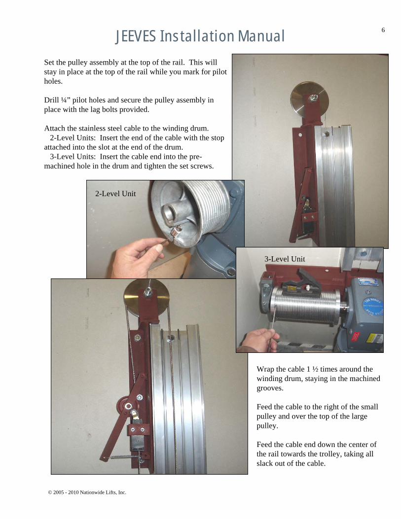
Set the pulley assembly at the top of the rail. This will stay in place at the top of the rail while you mark for pilot holes.
Drill ¼” pilot holes and secure the pulley assembly in place with the lag bolts provided.
Attach the stainless steel cable to the winding drum. 2-Level Units: Insert the end of the cable with the stop
attached into the slot at the end of the drum.3-Level Units: Insert the cable end into the pre-
machined hole in the drum and tighten the set screws.
Wrap the cable 1 ½ times around the winding drum, staying in the machined grooves.
Feed the cable to the right of the small pulley and over the top of the large pulley.
Feed the cable end down the center of the rail towards the trolley, taking all slack out of the cable.
2-Level Unit
3-Level Unit

© 2005 - 2010 Nationwide Lifts, Inc.
7JEEVES Installation Manual
IMPORTANT: Arrange the cable clamps such that the curve of the ‘U’ is wrapping around the cut end of the cable.
Excess cable can be cut or folded and zip-tied as shown.
IMPORTANT: Add weight to the trolley equivalent to the cab or mount the cab to adjust the slack cable switch on the sheave assembly.
Bottom Trolley stop 2-6” below level 1.
Trolley on bottom stop with cable slack
Attach the cable thimble to the trolley quick link. Slip three cable clamps onto the cable. Feed the cable end through the cable thimble and through the three cable clamps.
The cable must be attached to the trolley quicklink using provided materials…
The trolley should rest on the bottom trolley-stop with slack in the cable when fully tightened (see bottom pictures this page)
Cable Clamps
Cable Thimble

© 2005 - 2010 Nationwide Lifts, Inc.
8JEEVES Installation Manual
The limit switches are are used to sense the location of the dumbwaiter cab and stop it at the appropriate level.
The level #1 limit switch is located on the harness closest to the bullet connectors. Peel back the film on the #1 limit switch, exposing the double-sided tape.
Mount the limit switch on the rail approximately 1” above the bottom level of the 1st door opening. Mount the switch as shown, such that the holes line up with the groove along the side of the rail.
Mount the remaining switches, one for each level. There will be one extra switch that should be mounted 6 “ above the upper level switch. This last switch is called the Upper Final limit switch. Screw this switch into place prior to running in automatic mode for safety.
Use zip ties and sticky back squares provided to tie the wire down such that it will not be touched by pulleys, cable, or the moving trolley
Above the Upper Final limit switch is a length of wire with two bullet connectors on the end. Run this wire over the top of the rail and attach it to the Slack Cable limit switch. The Slack Cable limit switch is on the lower part of the pulley assembly.
Use zip ties and sticky back squares provided to tie the wire down such that it will not be touched by pulleys, cable, or the moving trolley.

© 2005 - 2010 Nationwide Lifts, Inc.
9JEEVES Installation Manual
Mount the controller in a location that will be convenient for viewing the text display. Position the controller such that cable harnesses can be run to the connectors mounted on sides and top of the controller, and the power cord can reach a power source.
A recommended location for the controller is the back of the machine access door.
IMPORTANT: MACHINE ACCESS DOOR MUST HAVE A LOCK AND REMAIN LOCKED AT ALL TIMES. MOVING PARTS WITHIN THE MACHINE AREA ARE VERY DANGEROUS TO CHILDREN.
Commercial jobs require a limit switch to be mounted inside the door opening to detect an open door and stop the unit from operating –see the provided limit switch.
Connect the Limit Switch harness to the cable labeled “limit switches” using the bullet connectors. Match each wire by color.
Slide the provided heat shrink tubing over the connectors. Apply a heat source to shrink the tubing, permanently securing the connectors.
Use zip ties and sticky back squares to hold harnesses out of path of moving trolley, cable, and the cab.
Use straps to secure the flex conduit and power cord in place. Route the flex conduit and power cord such that it does not interfere with moving cab, trolley, or cable.

© 2005 - 2010 Nationwide Lifts, Inc.
10JEEVES Installation Manual
Press the up arrow key for up direction and down arrow key for down direction to move the trolley to each level. Confirm that the limit switches are engaging when the trolley is at each level. Take special care to insure the Final Limit switch is engaged when the trolley travels beyond the upper level.
Adjust the limit switch locations such that each limit switch is centered on the trolley’s cam (steel piece that hits limit switches) when the trolley is level with each door. Keep in mind that the floor of the cab is ¾” thick on the wood cabs.
Note: The controller will exit Manual Mode after 10 minutes. You may have to set the controller back to Manual Mode a couple times during this process
Plug the controller into the power source ONLY AFTER YOU MAKE ALL WIRING CONNECTIONS even if the call box’s and door locks are not installed. The controller will immediately turn on and go through a self test procedure. Once the self test procedure is complete, the controller will likely show a screen representing Automatic Mode and an error such as “Door Ajar”.
Place the controller in Manual Mode: Press and hold the red M key for 20 seconds until the display shows “CAUTION Manual Mode”. ONLY THE FINAL UPPER LIMIT WILL FUNCTION IN MANUAL MODE.
CAUTION: YOU ARE NOW IN MANUAL MODE. DUMBWAITER WILL MOVE WHEN DOORS ARE OPEN. CHILDREN MUST NOT BE PRESENT WHEN RUNNING IN MANUAL MODE. CONFIRM PEOPLE AND OBJECTS ARE FREE FROM DUMBWAITER PATH.
Press the green A key on the controller to exit Manual Mode.
Once the limit switch locations are confirmed, the limit switches must be permanently mounted. Use the sharpened nail provided and a hammer to mark the location of mounting screws for the each limit switch. The mounting points should fall in the groove near the side of the rail.

© 2005 - 2010 Nationwide Lifts, Inc.
11JEEVES Installation Manual
Position the trolley at the 1st level.
Slide the dumbwaiter cab through the 1st level door rough opening and rest the cab on the trolley’s steel support.
Secure the cab to the trolley with the 3/8 bolts provided.
Place the controller in Manual Mode: Press and hold the red M key for 20 seconds until the display shows “CAUTION Manual Mode”.
CAUTION: YOU ARE NOW IN MANUAL MODE. DUMBWAITER WILL MOVE WHEN DOORS ARE OPEN. CHILDREN MUST NOT BE PRESENT WHEN RUNNING IN MANUAL MODE. CONFIRM PEOPLE AND OBJECTS ARE FREE FROM DUMBWAITER PATH.
IMPORTANT STEP: Use the up and down arrows on the controller to slowly move the dumbwaiter cab through the hoistway. MOVE THE CAB IN SMALL INCREMENTS, insuring with each increment that there are no clearance issues with hoistway walls, wire harnesses, or other obstructions. USE CAUTION as an obstruction in the up direction can cause damage and injury. Note: If the cab isn’t square with the hoistway along the length of the hoistway, shims may be needed between the cab and the trolley. If the cab moves out of square in different regions of the hoistway, then shims may be needed between the rail and the wall at the locations where the cab is not square.
If cab hits an obstruction in the down direction, and cable will have slack and the trolley brake will be engaged. To disengage the brake on the trolley, raise the cab upward. Verify the cable is in the proper position on the winding drum and not overlapping itself.
Press the green ‘A’ key on the controller to exit Manual Mode.
Remove the limit switch and drill 9/64 pilot holes at the nail marks (practice drilling holes in another location first). Use a thread tapping screw provided to cut threads in the holes.
Remove the double sided tape from the limit switches and install by hand with a screwdriver. Do not use a drill to fasten these screws as the limit switch may be damaged. Use caution not to over tighten and damage the limit switches. Push the limit switches as close to the wall as it will allow.

© 2005 - 2010 Nationwide Lifts, Inc.
12JEEVES Installation Manual
To mount the interlocks, use the paper template provided to mark mounting holes. Fold the template along the dotted line. Position the template in the upper corner of the door, opposite the hinges and use a center punch to push through the paper, marking the hole positions.
Install the doors at each level. DOORS MUST HAVE A LATCH TO KEEP THEM SHUT –INTERLOCKS ARE NOT A LATCH.
The interlocks are mounted in the upper corner of the door jam, on the side opposite the hinges. The interlock ‘keeper’ is mounted on the inside of the door such that it latches with the interlock when the door is closed.
Drill pilot holes for each of the mounting points. Use caution when drilling pilot holes for the keeper as you do not want to drill completely through the door. Fasten mounting screws hand tight using a screwdriver. Do not use a drill to fasten these screws as you will risk over tightening.
Mount the interlock such that the keeper locks in place when the door is shut.
Keeper

© 2005 - 2010 Nationwide Lifts, Inc.
13JEEVES Installation Manual
Install the call stations at each level. The call stations are labeled according to the level. Take care to use the appropriate call station at each level (the length of the cable is different for each level and the buttons are wired differently).
The interlocks have a cable with 4 connectors that attaches to a cable hanging from the call station. Run the wire through the wall to the call station. The connections should be made by matching the colors on each cable.
Run the harness from the call station through thehoistway wall to the location where the controller will be mounted.
If the harness is not run though the wall (behind the sheetrock) then the harness must be attached firmly to the wall such that the moving cab, trolley, and cable will not touch the harness.
Connect the call station harnesses to the cables hanging from the controller, carefully matching the colored wires. The connectors are labeled according to their level. Take care to match the appropriate harnesses to the labeled cables.

© 2005 - 2010 Nationwide Lifts, Inc.
14JEEVES Installation Manual
The dumbwaiter is now ready for Automatic Operation. Close the doors at every level.
View the controller display to determine if all safeties are in place. If the display shows “Automatic Mode” then the safeties are set and you can start operating the dumbwaiter.
If there are any errors, then you must troubleshoot. Use the troubleshooting notes and the display matrix provided in the following pages.
Normal Operation- All button lights are off- Controller display reads “Automatic Mode”- Press the call button for level ‘x’- Dumbwaiter cab moves to level ‘x’ and stops- Button light for level ‘x’ is lit solid during movement- Button light for level ‘x’ blinks fast while interlock is unlocked- Door interlock stayed unlocked for 10 seconds- Once door is closed again, the cab can be called to another level- If cab is already at level ‘x’, pressing the level ‘x’ button unlocks the interlock- Calls to other floors are recognized when dumbwaiter is moving and will travel to that floor after the door is locked- Calls to other floors are recognized when door is unlocked and will travel to that floor after door is locked
Level AdjustmentsWhen running in automatic mode with the cab completely assembled, you may find the need to adjust the limit switch levels. Test the leveling of the cab at each level, calling from up direction and down direction. Do this several times to determine if a limit switch is too high or low. If the level must be adjusted, take a measurement to determine the distance that the limit switch must be moved. Set the controller in Manual Mode and use the up / down arrow keys to move the cab out of the doorway, leaving access to the limit switch to be moved. Press the F1 button on the controller to unlock the 1st floor door (F2 for 2nd floor door, etc). Draw a line under and over the limit switch to designate the original location. Remove the limit switch and re-attach at the measured offset. You may choose to first test thelocation by mounting the limit switch with pressure sensitive tape, prior to permanently mounting it with screws. When the new location is confirmed, the limit switch must be permanently mounted. Use the sharpened nail provided and a hammer to mark the location of mounting screws for the each limit switch. The mounting points should fall in the groove near the side of the rail. Remove the limit switch and drill 9/64 pilot holes at the nail marks. Use a thread tapping screw provided to cut threads in the holes. Install the limit switch by hand with a screwdriver. Do not use a drill to fasten these screws as the limit switch may be damaged. Use caution not to over tighten and damage the limit switches. Push the limit switches as close to the wall as it will allow.

© 2005 - 2010 Nationwide Lifts, Inc.
15JEEVES Installation Manual
Troubleshooting Notes
The display on controller is blank… - Check power source to controller and the ribbon connection from the screen to the PLC.- Check fuses inside controller (if fuse holder is lit, then replace fuse)
Lights and display working, but dumbwaiter is not moving... - Check the overload switch inside the controller, Press the reset button on the overload switch- Check the motor wire connections and the 110V fuse in the controller.
Need to enter Manual Mode for troubleshooting or repair…- Press and hold the red M key for 20 seconds or until the display shows “CAUTION Manual Mode” CAUTION: YOU ARE NOW IN MANUAL MODE. DUMBWAITER WILL MOVE WHENDOORS ARE OPEN. CHILDREN MUST NOT BE PRESENT WHEN RUNNING IN MANUAL MODE. CONFIRM PEOPLE AND OBJECTS ARE FREE FROM DUMBWAITER PATH.
Need to unlock a door for troubleshooting…- Place the controller in Manual Mode- Press the F1 key on the controller to open door on floor #1, F2 for floor #2,
F3 for floor #3 and F4 for floor #4- Press the call button at each floor while in manual mode to unlock each door.
Door Ajar indication… - Controller text display will indicate the level that has the error- The button light will flash slowly indicating the level that has error- Verify that the keeper on the door is sliding into the interlock- Verify that the contacts in the interlock will touch the keeper- Verify that pins on the interlock and call station connectors are straight and appear in working order- Verify that the call station harness is plugged into the correct connector and locked in place- Verify door has a positive door latch (the interlock is not a door latch)
Slack Cable indication…- Place the controller in Manual Mode and unlock the doors to allow access to the hoistway- Inspect the cab and cable to determine if the cab is stuck on an obstacleUSE CAUTION IN MANUAL MODE – DO NOT MOVE DUMBWAITER WHEN INSPECTING THE INSIDE OF HOISTWAY- Remove any obstacles and insure cable is tight (lift on the cable to release the trolley brake)- Inspect Slack Cable limit Switch to confirm it is not triggered, adjust as needed
Upper Limit indication…- Place the controller in Manual Mode- Use down arrow on controller to move the cab downward- Inspect the limit switches mounted on rail to determine how cab could have hit Upper LimitUSE CAUTION IN MANUAL MODE – DO NOT MOVE DUMBWAITER WHEN INSPECTING THE INSIDE OF HOISTWAY- Make adjustments to insure all limit switches will be triggered appropriately

© 2005 - 2010 Nationwide Lifts, Inc.
16JEEVES Installation Manual
WARNING: Extreme caution must be taken when operating in Manual Mode. This mode is used strictly for troubleshooting and adjusting. Manual mode allows the user to directly control the movement of the dumbwaiter without door in place.
All lights offCAUTION Manual Mode
The Gate switch is not triggered, telling the controller that the gate is open and to stop all operation. Close the gate to start operation. **This feature is not included with all units.
All lights flashing slowly
Close Gate
The Slack Cable switch is triggered, telling the controller to stop all operation. Verify the cab has no obstructions and the cable is tight. If the cable is tight and the Slack Cable is still engaged, the Slack Cable limit switch may need to be adjusted.
All lights flashing slowly
Slack Cable Error
The Lower Limit access door switch is triggered, be sure the limit switch makes contact with the door when in the closed, locked position. **This feature is not included with all units.
All lights flashing slowly
Lower Limit Access Door Error
The Upper Limit switch is triggered, telling the controller not to allow the dumbwaiter to move any further in the upward direction. Use Manual Mode to move the cab down.
All lights flashing slowly
Upper Limit Error
The door latch sensor on level 4 recognizes the door as being open. The dumbwaiter will not operate until the door is closed and properly latched.
Level 4 light flashing slowly
Door Ajar Level 4
The door latch sensor on level 3 recognizes the door as being open. The dumbwaiter will not operate until the door is closed and properly latched.
Level 3 light flashing slowly
Door Ajar Level 3
The door latch sensor on level 2 recognizes the door as being open. The dumbwaiter will not operate until the door is closed and properly latched.
Level 2 light flashing slowly
Door Ajar Level 2
The door latch sensor on level 1 recognizes the door as being open. The dumbwaiter will not operate until the door is closed and properly latched.
Level 1 light flashing slowly
Door Ajar Level 1
This is the standard operating mode. Pressing button ‘x’ will send send the cab to floor ‘x’, then unlock the door for 10 seconds.
All lights offAutomatic ModeSelect a Level
NoteButtonsText Display

© 2005 - 2010 Nationwide Lifts, Inc.
17JEEVES Installation Manual
Top Stabilizer Roller
Larger cabs may require a Stabilizer Bracket. If this is provided with your dumbwaiter kit, this must be installed prior to installing the trolley to insure proper operation.
Secure with supplied hardware. (Do not push the cab towards the rail, let it hang naturally).
The measurement from the axel to the edge of the cab should be 3-3/4” – 4” centered on the cab.
Emergency car stop (commercial only)Run the unit in manual mode up to the final upper limit switch. Attach the 2” x 3” x 1/4” angle iron stop 1” above the car as an emergency safety stop. If the car hits this stop it will blow the 110Volt fuse. Replace the fuse and run in manual mode to be sure the top final limit is working.
Bottom Stabilizer Roller
Attach if provided the opposite guide rail roller bracket with the provided hardware. Let the cab hang naturally when tightening the bolts. Run the unit in manual mode to ensure proper alignment.
This will provide a very stable cab for loading and unloading.
The recommended opposite guide rail (not supplied) is a 2” x 2” x 1/4” steel or aluminum angle.
APPENDIX AInstallation of Stabilizer Brackets

© 2005 - 2010 Nationwide Lifts, Inc.
18JEEVES Installation Manual
Mount the switch in the hole provided at the base of the gate. The magnetic switch will be active when the gate is closed as the gate will have the magnet installed at the factory.
Commercial dumbwaiters require a gate switch. This switch signals the controller when the gate is closed. The controller will not allow the cab to move unless the gate is closed.
APPENDIX BInstallation of Gate Switch and
Travel Cable
Tie the cable to the underside of the cab to provide strain relieve for the connection to the switch.
The cable will connect to the controller, to the cable labeled ‘travel cable’.

© 2005 - 2010 Nationwide Lifts, Inc.
19JEEVES Installation Manual
APPENDIX BInstallation of Gate Switch and
Travel Cable
VERY IMPORTANT: The travel cable must be hung inside the hoistway with an anchor point at the halfway point of the dumbwaiter travel. The cable should be hung such that is avoids the motor and other dumbwaiter components. See next page for diagrams.
The anchor point must be rigid enough to hold the weight of the travel cable. A - J hook is provided to hang the travel cable hanger, use a sticky back and zip tie to keep the travel cable close to the wall
VERY IMPORTANT: When the dumbwaiter cab is at the lowest level, the travel cable should have slack. It should hang above the motor assembly to avoid catching on the drum.

© 2005 - 2010 Nationwide Lifts, Inc.
20JEEVES Installation Manual
APPENDIX B (cont.)Installation of Gate Switch and
Travel Cable
Cab
MotorTravel Cable
Cab
Motor
Travel Cable
Cable Fastened at halfway point
Cable Fastened at halfway point
Cab at lower level Cab at upper level

© 2005 - 2010 Nationwide Lifts, Inc.
21JEEVES Installation Manual
Commercial dumbwaiters require control cable to be run in EMT conduit. Most codes allow for 6” of wire to run outside the conduit.
If your codes require complete EMT use flex from the junction box to allow for limit switch adjustment. Do not cut the wire, disconnect the limit switches and pull the wire to the junction box. Fold the wire in half to go through the flex and re-connect to the limit switch. The switch will need to be installed vertical with double sticky tape and one self tapping screw as shown, you will also need the adjustable limit roller arm provided by us,you will also need the adjustable limit roller arm provided by us to 4-3/4” from the wall to the end of the roller wheel..
APPENDIX CInstallation of EMT
Proper installation of the EMT will insure the control cable cannot catch on any moving parts.
Consult with your local inspector prior to installation to familiarize with the local codes.

© 2005 - 2010 Nationwide Lifts, Inc.
22JEEVES Installation Manual
APPENDIX DOverhead motor and sheave
Mount motor as close to the top of the shaft as possible using the centerline on the motor frame to align with shaft centerline.
Mount the sheave assembly the maximum distance down from the winding drum (minimum 36” from the winding drum to the first sheave wheel) using the centerline on the sheave assembly to align with the shaft centerline.
Motor direction wires need to be connected as follows: The blue wire from the controller will connect to the #5 motor wire and the yellow wire from the controller will connect to #8 motor wire. These will already be color coded correctly from the factory.