jc2 physics h2 2018 - sg test paper
TRANSCRIPT
© DHS 2018 9749/Prelim/01/18 [Turn over
DUNMAN HIGH SCHOOL Preliminary Examinations Year 6 Higher 2
PHYSICS Paper 1 Multiple Choice
9749/01
September 2018
1 hour
Additional Materials: Multiple Choice Answer Sheet
READ THESE INSTRUCTIONS FIRST
Write in soft pencil.
Do not use staples, paper clips, highlighters, glue or correction fluid.
Write your name, class and index number on the Answer Sheet in the spaces provided unless this has been
done for you.
DO NOT WRITE IN ANY BARCODES.
There are thirty questions on this paper. Answer all questions. For each question there are four possible
answers A, B, C and D.
Choose the one you consider correct and record your choice in soft pencil on the separate Answer Sheet.
Read the instructions on the Answer Sheet very carefully.
Each correct answer will score one mark. A mark will not be deducted for a wrong answer.
Any rough working should be done in this booklet.
The use of an approved scientific calculator is expected, where appropriate.
This document consists of 14 printed pages and 0 blank page.
CANDIDATE NAME
CLASS INDEX NUMBER
2
© DHS 2018 9749/Prelim/01/18
Data speed of light in free space, c = 3.00 × 10⁸ m s−1 permeability of free space, μo = 4π × 10−7 H m−1 permittivity of free space, εo = 8.85 × 10⁻¹² F m−1 (1/(36π)) × 10−9 F m−1
elementary charge, e = 1.60 × 10⁻¹⁹ C the Planck constant, h = 6.63 × 10⁻³⁴ J s unified atomic mass constant, u = 1.66 × 10⁻²⁷ kg rest mass of electron, me = 9.11 × 10⁻³¹ kg rest mass of proton, mp = 1.67 × 10⁻²⁷ kg molar gas constant, R = 8.31 J K−1 mol−1
the Avogadro constant, NA = 6.02 × 10²³ mol−1 the Boltzmann constant, k = 1.38 × 10⁻²³ J K−1 gravitational constant, G = 6.67 × 10⁻¹¹ N m2 kg−2 acceleration of free fall, g = 9.81 m s−2

3
© DHS 2018 9749/Prelim/01/18 [Turn over
Formulae
uniformly accelerated motion s = 21
2ut at+
v2 = 2 2u as+
work done on/by a gas W = pΔV hydrostatic pressure p = ρgh
gravitational potential φ = Gm
r−
temperature T/K = T/oC + 273.15
pressure of an ideal gas p = 21
3
Nmc
V
mean translational kinetic energy of an ideal gas molecule E = 3
2kT
displacement of particle in s.h.m. x = x0 sin ωt velocity of particle in s.h.m. v = v0 cos ωt
= 2 20 x xω± −
electric current I = Anvq resistors in series R = R1 + R2 + . . . resistors in parallel 1/R = 1/R1 + 1/R2 + . . .
electric potential V = 04
Q
rπε
alternating current / voltage x = x0 sin ωt
magnetic flux density due to a long straight wire B = 2
o
d
μπ
I
magnetic flux denxity due to a flat circular coil B = 2oN
r
μ I
magnetic flux density due to a long solenoid B = onμ I radioactive decay x = x0 exp(−λt)
decay constant λ = 1
2
ln2
t

4
© DHS 2018 9749/Prelim/01/18
1 Determine the angle between two equal forces F when their resultant force is also equal to F.
A 45o B 60o C 120o D 135o
2 An un-calibrated analogue voltmeter P is connected in parallel with another voltmeter Q which is known to be accurately calibrated. For a range of values of potential difference (p.d.), readings are taken from the two meters.
The diagram shows the calibration graph obtained.
The graph shows that meter P has a zero error. This meter is now adjusted to remove this zero error. When the meter is re-calibrated, the gradient of the calibration graph is found to be unchanged.
What is the new scale reading on meter P when it is used to measure a p.d. of 5.0 V?
A 6.6 B 6.7 C 7.2 D 7.4
3 A projectile of mass 2.0 kg is launched on the Earth with some initial velocity. Another projectile
of mass 4.0 kg is launched on the Moon with the same initial velocity. The acceleration of free fall on the Moon is 1.6 m s−2.
Neglecting air resistance, what is the ratio range of projectile on the Earth
range of projectile on the Moon?
A 0.16 B 0.33 C 3.3 D 6.1

5
© DHS 2018 9749/Prelim/01/18 [Turn over
4 A golf ball is hit from point A on the ground and moves through the air to point B as shown in the figure which is not drawn to scale.
The ground slopes downhill with constant gradient of angle 8.2° to the horizontal. The ball has
an initial velocity of 63 m s−1 at an angle of θ to the horizontal. Time taken for the ball to travel from A to B is 4.9 s.
Determine the angle θ.
A 8.0º B 10º C 12º D 14º 5 Water flows out of a pipe and hits a wall.
When the jet of water hits the wall, it has horizontal velocity v and cross-sectional area A. The density of the water is ρ. The water does not rebound from the wall. What is the force exerted on the wall by the water?
A ρv
A B
2ρv
A C ρAv D 2ρAv
8.2°
θ

6
© DHS 2018 9749/Prelim/01/18
6 In order to support a load W, four light hinged rods P, Q, R and S are connected as shown below and mounted in a vertical plane.
Which rods are in compression and which in tension? in compression in tension
A P Q, R, S
B P, Q R, S
C Q, R P, S
D R, S P, Q
7 A car of mass 1100 kg is travelling at a constant speed of 15 m s−1 up a slope inclined at 10º
to the horizontal. The combined frictional forces acting on the car are directed down the slope
and are equal to 5
W, where W is the weight of the car.
What is the useful output power of the car’s engine?
A 28 kW B 32 kW C 60 kW D 190 kW
8 An old-fashioned 60 W lamp converts 95% of its energy supply into heat. A 4.0 W modern lamp has the same power output of light as the old-fashioned lamp.
What is the efficiency of the modern lamp? A 5.0% B 6.7% C 75% D 95%
P
Q R
S
W

7
© DHS 2018 9749/Prelim/01/18 [Turn over
9 The reading of a speedometer fitted to the front wheel of a bicycle is directly proportional to
the angular velocity of the wheel. A certain speedometer is correctly calibrated for use with a wheel of diameter 61 cm but, by mistake, is fitted to a 51 cm wheel.
What is the value of indicated speed actual speed
100%?actual speed
− ×
A +16% B −16% C +20% D −20%
10 Two large masses, one of mass M, the other of mass 4
M, are positioned as shown.
A small mass is placed at point P such that it experiences zero gravitational force from the masses.
What is the ratio R
r?
A 1
4 B
1
2 C 2 D 4
11 Io and Ganymede are moons of Jupiter. The orbital period of Ganymede is four times that of Io. Io’s orbital radius is 4.20 × 10⁸ m.
What is the orbital radius of Ganymede?
A 91 06 m10 . ×
B 91 68 m10 . ×
C 93 36 m10 . ×
D 102 70 10 m. ×

8
© DHS 2018 9749/Prelim/01/18
12 In deriving the equation 21
3pV Nm c= in the simple kinetic theory of gases, which of the
following is not taken as a valid assumption?
A The molecules suffer negligible change of momentum on collision with the walls of the container.
B Collisions with the walls of the container and with other molecules cause no change in
the average kinetic energy of the molecules. C The duration of a collision is negligible compared with the time between collisions. D The volume of the molecules is negligible compared with the volume of the gas.
13 Atoms of neon are at a temperature such that the root mean square (r.m.s.) speed of its atoms is 400 m s−1.
What will be the r.m.s. speed of molecules of hydrogen at the same temperature?
Mass of neon atom = 20 u. Mass of hydrogen molecule = 2 u.
A 130 m s−1 B 400 m s−1 C 1300 m s−1 D 4000 m s−1
14 A particle performs simple harmonic motion according to the equation
x = 2.0 cos (ωt)
where its displacement x is measured in cm and time t is measured in s.
If the angular frequency ω is π rad s−1, what is the total distance travelled by the particle from t = 0.0 s to t = 1.5 s?
A 0 cm B 2.0 cm C 3.0 cm D 6.0 cm

9
© DHS 2018 9749/Prelim/01/18 [Turn over
15 An object is executing simple harmonic motion along the x-axis between P (a, 0) and Q (−a, 0) about the origin O. The kinetic energy of the particle is EK, its potential energy is EP and the total energy is ET.
When the particle is mid-way between O and Q, what are the values of K
T
E
E and P
T
E
E?
K
T
E
E P
T
E
E
A 1
4 3
4
B 1
2 1
2
C 3
4 1
4
D 1
8 7
8
16 A beam of plane-polarised light of intensity I falls normally on a thin sheet of polaroid.
If the transmitted beam has an intensity of 4
I, what is the angle between the plane of incident
polarisation and the polarising direction of the polaroid?
A 22.5o B 30o C 45o D 60o
17 S1 and S2 are loudspeakers facing each other and emitting continuous sound waves of frequency 1100 Hz. M is a small microphone which runs on a straight track between S1 and S2 at a speed of 30 m s−1. The sound received by M will fluctuate with a frequency f.
If the velocity of sound is 330 m s−1, what is the value of f?
A 100 Hz B 200 Hz C 400 Hz D 800 Hz
x
y
O
P Q
(a,0) (−a,0)

10
© DHS 2018 9749/Prelim/01/18
18 Light of wavelength 600 nm is incident on a pair of slits. Fringes with a spacing of 4.0 mm are formed on a screen.
What will be the fringe spacing when the wavelength of the light is changed to 400 nm and the separation of the slits is doubled?
A 1.3 mm B 3.0 mm C 5.3 mm D 12 mm
19 A positively charged oil droplet is held stationary in an electric field of strength E.
A different droplet of the same oil is held stationary in an electric field of different strength. The droplet has half the charge and twice the radius of the original droplet.
What is the electric field strength? A 2E B 4E C 8E D 16E 20 A negative point charge is surrounded symmetrically by six positive point charges at distance
r as shown in diagram.
How much work is done by the forces of attraction when the point charge at the centre is removed to infinity?
A 26
4 o
Q
rπε− B
26
4 o
Q
rπε+ C
2
2
6
4 o
Q
rπε− D
2
2
6
4 o
Q
rπε+
r
+Q +Q
+Q +Q
+Q −Q +Q

11
© DHS 2018 9749/Prelim/01/18 [Turn over
21 A cell with internal resistance 1.2 Ω is connected in the circuit as shown.
The graph shows the variation with time t of the voltmeter reading V. At time t = 0 s, switch S
is closed. At time t = t1, switch S is opened and a rise in the voltmeter reading V was observed. What is the value of X? A 2.2 V B 2.4 V C 3.6 V D 4.2 V
22 The circuit diagram shows a network of resistors.
What is the effective resistance between the points X and Y?
A 3.5 Ω B 7.6 Ω C 10.5 Ω D 15.0 Ω
12 Ω 30 Ω 18 Ω
4.5 Ω
V
8.4 Ω S
1.2 Ω
V / V
t / s
2.1
X
t10 0
X
Y

12
© DHS 2018 9749/Prelim/01/18
23 A 1.5 m by 0.5 m light and rigid rectangular conducting frame is pivoted along its longer sides with a weight Z hung on one shorter side as shown. A uniform horizontal magnetic field B of flux density 0.050 T is applied at right-angles to the section XY of the frame.
When a current passes through the section XY of the frame, which combination of the magnitude and direction of current flowing in section XY, and the weight Z makes the frame horizontal?
magnitude of current in section XY
direction of current in section XY
Z / N
A 1.96 A from X to Y 0.049
B 1.96 A from Y to X 0.098
C 3.92 A from X to Y 0.196
D 3.92 A from Y to X 0.098
24 In certain experiments involving scattering of electrons by nucleus, a beam of electrons of kinetic energy 250 eV are needed. It can be obtained by passing a beam of electrons of different kinetic energies through a velocity selector as shown, with plate Y at a higher potential with respect to plate X.
Which of the following gives the correct effect on electrons that enter the velocity selector with kinetic energies that differs from the required 250 eV?
electrons with kinetic energies greater than 250 eV
electrons with kinetic energies lower than 250 eV
A impact on plate X impact on plate X
B impact on plate X impact on plate Y
C impact on plate Y impact on plate X
D impact on plate Y impact on plate Y
X
Y 1.0 m 0.5 m
B Z
0.5 m
electrons all have the same kinetic energy 250 eV
X
Y
electrons of different kinetic
energies
uniform magnetic field region

13
© DHS 2018 9749/Prelim/01/18 [Turn over
25 A coil of 160 turns and area 0.20 m2 is placed with its axis parallel to a magnetic field in the x-direction. The magnetic flux density changes from 0.40 T in the positive x-direction to 0.40 T in the negative x-direction in 2.0 s.
If the resistance of the coil is 16 Ω, what is the rate of energy generated in the coil? A 5 W B 10 W C 13 W D 20 W
26 A sinusoidal alternating current of peak value Io passes through a resistor of resistance R. The mean power developed by the current in the resistor is P.
Another sinusoidal alternating current passes through a resistor of resistance 2R. If the mean power developed by this current in it is 4P, what is the root-mean-square value of this current?
A 0.7 Io B Io C 1.4 Io D 2.0 Io
27 When electromagnetic radiation of frequency f irradiates a metal surface, electrons are emitted and the measured stopping potential is Vs. The frequency of the incident radiation is halved to 0.5f.
What change occurs in the stopping potential? A The stopping potential decreases to less than 0.5Vs.
B The stopping potential decreases to 0.5Vs.
C The stopping potential decreases to more than 0.5Vs.
D The stopping potential remains at Vs.
28 A proton has a kinetic energy of 1.00 MeV.
If its momentum is measured with an uncertainty of 1.00 %, what is the minimum uncertainty in its position?
A 5.64 × 10⁻¹⁴ m
B 9.08 × 10⁻¹⁴ m
C 2.87 × 10⁻¹² m
D 9.77 × 10⁻¹⁰ m

14
© DHS 2018 9749/Prelim/01/18
29 Two deuterium nuclei fuse together to form a Helium-3 nucleus, with the release of a neutron. The reaction is represented by
+ → + +2 2 3 1
1 1 2 0H H He n energy
The binding energies per nucleon are: for 2
1H 1.09 MeV,
for 32He 2.54 MeV.
How much energy is released in this reaction? A 0.36 MeV B 1.45 MeV C 3.26 MeV D 5.44 MeV
30 Nuclide X decays to stable nuclide Y with a half-life of T years.
Geologists are sure that nuclide Y found in a particular rock sample has all came from nuclide X which was present when the rock formed.
The rock is thought to be 3T years old.
What is the expected ratio number of atoms of X
number of atoms of Y for this rock?
A 1
6 B
1
7 C
1
8 D
1
9
- END OF PAPER -

© DHS 2018 9749/Prelim/02/18 [Turn over
DUNMAN HIGH SCHOOL Preliminary Examinations Year 6 Higher 2
PHYSICS Paper 2 Structured Questions Candidates answer on the Question Paper.
No Additional Materials are required.
9749/02
September 2018
2 hours
READ THESE INSTRUCTIONS FIRST
Write your class, index number and name in the spaces at the top of this page.
Write in dark blue or black pen on both sides of the paper.
You may use a soft pencil for any diagrams, graphs or rough working.
Do not use staples, paper clips, highlighters, glue or correction fluid.
DO NOT WRITE IN ANY BARCODES.
The use of an approved scientific calculator is expected, where appropriate.
Answer all questions.
At the end of the examination, fasten all your work securely together.
The number of marks is given in brackets [ ] at the end of each question or part
question.
For Examiner’s Use
1 12
2 7
3 8
4 8
5 8
6 8
7 9
8 20
Total 80
This document consists of 21 printed pages and 1 blank page.
CANDIDATE NAME
CLASS INDEX NUMBER

2
© DHS 2018 9749/Prelim/02/18
Data speed of light in free space, c = 3.00 × 10⁸ m s−1 permeability of free space, μo = 4π × 10−7 H m−1 permittivity of free space, εo = 8.85 × 10⁻¹² F m−1 (1/(36π)) × 10−9 F m−1
elementary charge, e = 1.60 × 10⁻¹⁹ C the Planck constant, h = 6.63 × 10⁻³⁴ J s unified atomic mass constant, u = 1.66 × 10⁻²⁷ kg rest mass of electron, me = 9.11 × 10⁻³¹ kg rest mass of proton, mp = 1.67 × 10⁻²⁷ kg molar gas constant, R = 8.31 J K−1 mol−1
the Avogadro constant, NA = 6.02 × 10²³ mol−1 the Boltzmann constant, k = 1.38 × 10⁻²³ J K−1 gravitational constant, G = 6.67 × 10⁻¹¹ N m2 kg−2 acceleration of free fall, g = 9.81 m s−2

3
© DHS 2018
9749/Prelim/02/18 [Turn over
Formulae
uniformly accelerated motion, s = ut + 1
2at2
v2 = u2 + 2as
work done on/by a gas, W = pΔV hydrostatic pressure, p = ρgh gravitational potential, φ = −Gm/r temperature, T/K = T/oC + 273.15
pressure of an ideal gas, p = 21
3
Nmc
V< >
mean translational kinetic energy of an ideal gas molecule, E = kT2
3
displacement of particle in s.h.m., x = x0 sin ωt velocity of particle in s.h.m., v = v0 cos ωt
= ±ω 22 xxo −
electric current, I = Anvq resistors in series, R = R1 + R2 + . . . resistors in parallel, 1/R = 1/R1 + 1/R2 + . . .
electric potential, V = r
Q
oπε4
alternating current / voltage, x = x0 sin ωt
magnetic flux density due to a long straight wire, B = 0
2 d
Iμπ
magnetic flux denxity due to a flat circular coil, B = 0
2
N
r
Iμ
magnetic flux density due to a long solenoid, B = 0nIμ
radioactive decay, x = x0 exp(−λt)
decay constant, λ = 1
2
ln2
t

4
© DHS 2018 9749/Prelim/02/18
For Examiner’s
Use 1 (a) A liquid L fills a container of very large uniform cross-sectional area to a certain depth.
Another liquid M is now added to the container. The two liquids do not mix as shown in
Fig. 1.1. The total depth of the liquids is 0.17 m.
Fig. 1.1 (not to scale)
Fig. 1.2 shows how the pressure p inside the liquids varies with height x above the
base of the container.
Fig. 1.2
Use Fig. 1.2 to
(i) state the value of the atmospheric pressure,
atmospheric pressure = ………………………………. Pa [1]
(ii) determine the density of liquid M.
density = ………………………………. kg m-3 [2]
liquid M in a container of very large uniform cross-sectional area
liquid L in the same container
0.17 m
base of container

5
© DHS 2018
9749/Prelim/02/18 [Turn over
For Examiner’s
Use (b) Above the liquids, a spring is attached at one end to a fixed point and hangs vertically
with a cube attached to the other end. The cube is initially held so that the spring has
zero extension as shown in Fig. 1.3.
Fig. 1.3 (not to scale)
The cube has weight 4.0 N and sides of length 5.1 cm. The cube is released and sinks
into the liquids as the spring extends. The cube reaches equilibrium with its base at a
depth of 10.0 cm below the top surface of the liquid M, as shown in Fig. 1.3.
(i) Determine the upthrust acting on the cube.
upthrust = ………………………………. N [3]
(ii) Calculate the magnitude of the force exerted on the spring by the cube when it is in
equilibrium in the liquids.
force = ………………………………. N [1]
liquid M
liquid L 10.0 cm

6
© DHS 2018 9749/Prelim/02/18
For Examiner’s
Use (c) Suggest how to check that the elastic limit of the spring is not exceeded.
…...………………………………………………………………………..…………………….....
………………………………………………………………………..……………………...... [1]
(d) Two identical balls are placed in a smooth glass container as shown in Fig. 1.4. Each
ball has a mass of 170 g. Their centres and point A lies on a straight line as shown by
the dotted line.
Fig. 1.4
(i) Determine the magnitude of the horizontal force by the container on the upper
ball.
horizontal force = ………………………………. N [2]
(ii) Hence, or otherwise, determine the magnitude of the force exerted by the lower
ball on the upper ball.
force = ………………………………. N [2]
A
Balls
Container

7
© DHS 2018
9749/Prelim/02/18 [Turn over
For Examiner’s
Use 2 Fig. 2.1 shows the variation with distance from the centre of the Earth of the gravitational
field strength g.
Fig. 2.1
(a) Use Fig. 2.1 to determine the gravitational force on a man-made satellite of mass 20 000 kg at a distance of 8200 km from the centre of the Earth.
gravitational force = ...................................................... N [2]
(b) Calculate the speed of the satellite in (a) for it to be circling the Earth at constant speed.
speed = ................................................. m s−1 [2]

8
© DHS 2018 9749/Prelim/02/18
For Examiner’s
Use (c) (i) State what is meant by gravitational potential.
…...………………………………………………………………………..…………………….....
………………………………………………………………………..………………...….….. [1]
(ii) Use Fig. 2.1 to estimate the gravitational potential at a distance of 10 000 km from the
centre of the Earth.
gravitational potential = ................................................ J kg−1 [2]
3 (a) A small ball rests at point P on a curved track of radius r, as shown in Fig. 3.1.
The ball is moved a small distance to one side and is then released. The horizontal displacement x of the ball is related to its acceleration a towards P by the expression
a= gx
r
where g is the acceleration of free fall. (i) Show that the ball undergoes simple harmonic motion.
………………………………………………………………………..…………………….....
………………………………………………………………………..…………………….....
………………………………………………………………………..…………………….....
………………………………………………………………………..…………………… [2]
Fig. 3.1
x
P
curved track, radius r

9
© DHS 2018
9749/Prelim/02/18 [Turn over
For Examiner’s
Use (ii) The radius r of curvature of the track is 28 cm.
Determine the time interval τ between the ball passing point P and then returning to point P.
τ = ………………. s [3]
(b) The variation with time t of the displacement x of the ball in (a) is shown in Fig. 3.2.
Some moisture now forms on the track, causing the ball to come to rest after approximately 15 oscillations.
On the axes of Fig. 3.2, sketch the variation with time t of the displacement x of the ball for the first two periods after the moisture has formed. Assume the moisture forms at t = 0. [3]
Fig. 3.2
10
© DHS 2018 9749/Prelim/02/18
For Examiner’s
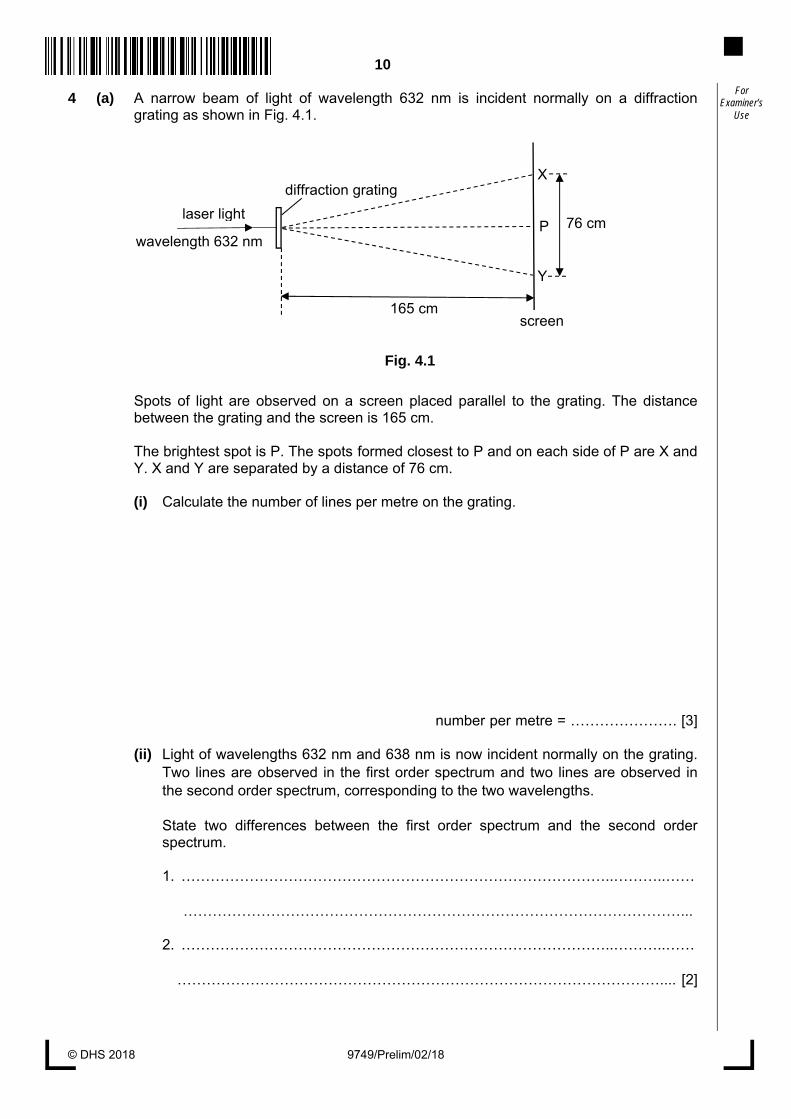
Use 4 (a) A narrow beam of light of wavelength 632 nm is incident normally on a diffraction
grating as shown in Fig. 4.1. Spots of light are observed on a screen placed parallel to the grating. The distance
between the grating and the screen is 165 cm. The brightest spot is P. The spots formed closest to P and on each side of P are X and
Y. X and Y are separated by a distance of 76 cm.
(i) Calculate the number of lines per metre on the grating.
number per metre = …………………. [3]
(ii) Light of wavelengths 632 nm and 638 nm is now incident normally on the grating. Two lines are observed in the first order spectrum and two lines are observed in the second order spectrum, corresponding to the two wavelengths.
State two differences between the first order spectrum and the second order spectrum.
1. ……………………………………………………………………………..………..……
…………………………………………………………………………………………...
2. ……………………………………………………………………………..………..…… ……………………………………………………………………………………….... [2]
Fig. 4.1
diffraction grating
laser light
wavelength 632 nm
X
Y
P 76 cm
165 cmscreen

11
© DHS 2018
9749/Prelim/02/18 [Turn over
For Examiner’s
Use (b) (i) The grating in (a) is now rotated about an axis parallel to the incident light, as
shown in Fig. 4.2.
State what effect, if any, this rotation will have on the positions of the spots P, X and Y.
………………………………………….………………………………………………….....
……….…………………………………………………………………………………… [2]
(ii) In another experiment using the apparatus in (a), it was noticed that the distances
XP and PY, as shown in Fig. 4.1, are not equal. Suggest a reason for this difference.
……….…………………………………………………………………………………… [1]
5 (a) (i) State what is meant by the terms electric field and electric field strength.
electric field ……..........................................................................................................
……..………………………………………………………………………………………….
electric field strength ...................................................................................................
……...................................................................................................................... [2]
Fig. 4.2
laser light
diffraction grating
diffraction grating
laser light
before rotation after rotation
12
© DHS 2018 9749/Prelim/02/18
For Examiner’s
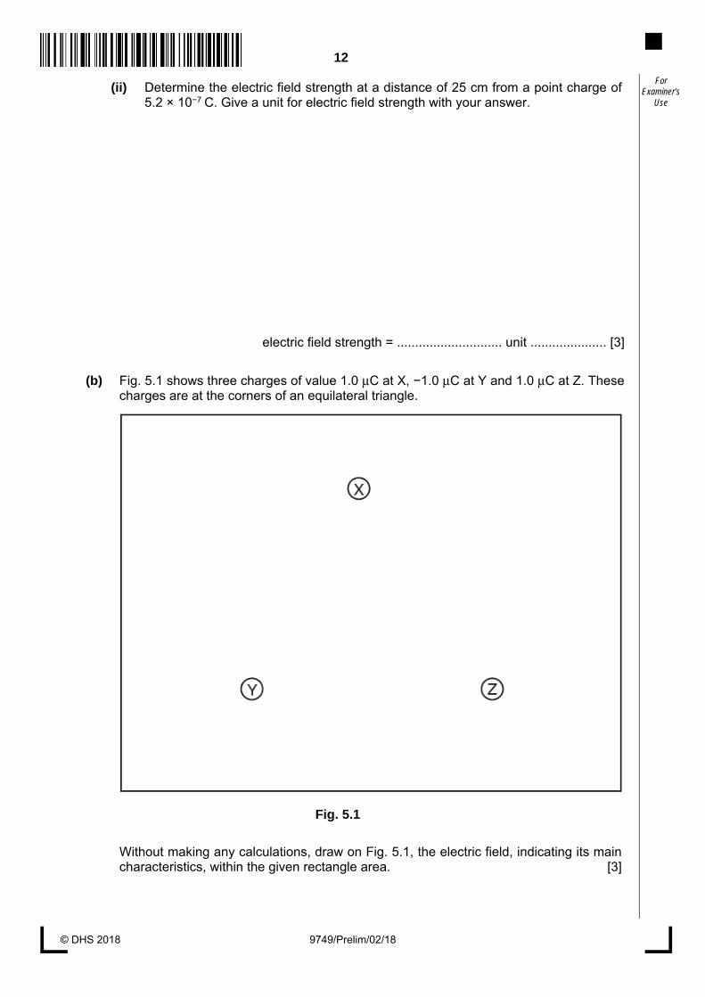
Use (ii) Determine the electric field strength at a distance of 25 cm from a point charge of
5.2 × 10⁻⁷ C. Give a unit for electric field strength with your answer.
electric field strength = ............................. unit ..................... [3]
(b) Fig. 5.1 shows three charges of value 1.0 μC at X, −1.0 μC at Y and 1.0 μC at Z. These charges are at the corners of an equilateral triangle.
Fig. 5.1
Without making any calculations, draw on Fig. 5.1, the electric field, indicating its main characteristics, within the given rectangle area. [3]

13
© DHS 2018
9749/Prelim/02/18 [Turn over
For Examiner’s
Use 6 (a) Two identical wires A and B, are placed parallel to each other as shown in Fig. 6.1.
Both wires carry a current of 90.0 A towards the left.
Fig. 6.1
Explain why both wires experience a force. …………………………………………………………………...………..…………………….....
…………………………………………………………………...………..……………………..... …………………………………………………………………...………..…………………….....
………………………………………………………………………..……………………...... [2]
(b) Fig. 6.2 shows only the wire A carrying a current of 90.0 A towards the left. Point P lies in the plane of the paper containing wire A, at a distance 50.0 cm directly above wire A. At P, a proton is travelling directly towards the wire with a speed v = 1.0 × 10³ m s-1. Ignore the effects of the Earth’s magnetic field.
Fig. 6.2
wire B
wire A
direction of current
50.0 cm
wire A
direction of current
v
P proton

14
© DHS 2018 9749/Prelim/02/18
For Examiner’s
Use (i) Calculate the radius of the path of the proton when it is at P.
radius = ……………........…….... m [3]
(ii) Explain how the path of the proton is affected by the magnetic field produced by the current in wire A as it moves in the region between P and wire A.
………………………………………….………………………………………………….....
………………………………………….………………………………………………….....
………………………………………….…………………………………………………..... ………………………………………….………………………………………………….....
………………………………………….………………………………………………….....
………………………………………….………………………………………………… [3]
7 A particular X-ray tube uses molybdenum (Mo) as the target element and another X-ray tube uses tungsten (W). An accelerating potential of 25 kV is applied to both tubes, giving rise to continuous spectrums being formed. The atomic number Z of molybdenum is 42 while that of tungsten is 74.
(a) Explain, with reference to the mechanism of X-ray production,
(i) how the continuous spectrum is formed, and
….……………………………………………….…………………………………………… .……………………………………………….……………………………………………… ……………………………………………….………………………………………………..
..……….………………………………………………………………………………….. [2]

15
© DHS 2018
9749/Prelim/02/18 [Turn over
For Examiner’s
Use (ii) why the minimum wavelength produced is the same for both target elements.
….……………………………………………….…………………………………………… .……………………………………………….……………………………………………… ……………………………………………….………………………………………………..
..……….………………………………………………………………………………….. [2]
(b) Characteristic peaks Kα and Kβ occur for molybdenum, but not for tungsten at an accelerating potential of 25 kV. In order to obtain the characteristic spectra for tungsten, the accelerating potential has to be increased beyond 25 kV.
Explain (i) why the intensity of the Kα X-ray is typically greater than the Kβ X-ray for
molybdenum.
……………………………………………….……………………………………………….. ..……….………………………………………………………………………………….. [1]
(ii) why the characteristic spectra for tungsten only appear when the accelerating potential is greater than that necessary to produce characteristic spectra for molybdenum.
……………………………………………….……………………………………………….. ……………………………………………….………………………………………………..
..……….………………………………………………………………………………….. [2]
(c) The X-ray spectrum of molybdenum has a particular characteristic spectral line of wavelength 6.6 × 10⁻¹¹ m, produced by electrons making transitions between two energy levels of the molybdenum atom.
Calculate, in electron-volts, the energy of an X-ray photon of wavelength 6.6 × 10⁻¹¹ m.
energy = ……………........…….... eV [2]

16
© DHS 2018 9749/Prelim/02/18
For Examiner’s
Use 8 The Singapore Mass Rapid Transit (SMRT) started its first train services in 1987. It was a
massive nationwide project, beginning from the physical construction of the train tracks to the planning of the train arrival frequency. Amongst other professionals, the project involved the close collaboration of civil and structural engineers as well as transport engineers.
The Kawasaki Heavy Industries (KHI) C151 train as shown in Fig. 8.1, is Singapore’s first generation of SMRT train fleet and has been in passenger service since 7 November 1987. All of the 396 KHI cars are built from 1986 to 1989 by four manufacturers in the consortium led by Kawasaki Heavy Industries.
Fig. 8.1
Technical Specifications: Manufacturer: Kawasaki Heavy Industries, Nippon Sharyo, Tokyu Car
Corporation, Kinki Sharyo Number built: 396 cars (66 trains) Car body Construction: Aluminium-alloy construction Maximum Speed: 90 km h-1 (Design) 80 km h-1 (Service)
Train Length: 138 m (6 cars) Width: 3.2 m Height: 3.7 m Train Mass: 286000 kg (fully laden) Doors: 1.45 m, 8 per car Seating Capacity: 208 seats

17
© DHS 2018
9749/Prelim/02/18 [Turn over
For Examiner’s
Use Fig. 8.2 shows a section of an elevated MRT track with a train on it. From the structural aspect, the structure load is being supported as follows:
1. Each car, with passengers in it, has its load supported by the beam below it. Car 2 is
thus supported by beam 2.
2. Car 2 and beam 2 are both supported by columns 1 and 2.
Fig. 8.2
The following set of simplified data is provided. Weight of 1 empty car = 350 kN Weight of 1 beam = 380 kN Weight of 1 column = 100 kN
(a) Explain what is meant by train arrival frequency.
………………………………………………………………………..……………………...... [1]
(b) An alloy is a combination of metals or of a metal and another element.
Suggest why trains are commonly made of aluminium alloy.
………………………………………………………………………..……………………...... [1]
ground
car 1 car 2 car 3
beam 1 beam 2 beam 3
column 1 column 2

18
© DHS 2018 9749/Prelim/02/18
For Examiner’s
Use (c) When a train with no passengers in it, and is at the position shown in Fig. 8.2,
(i) indicate on Fig. 8.3, the portion of beam 2 that is under compression and the
portion under tension when the car is on beam 2. [1]
Fig. 8.3
(ii) calculate the total normal reaction force acting on beam 2 due to the supporting columns.
normal force = …….………........…….... N [1]
(iii) state the total load that the top of column 1 has to take.
total load = …….………........…….... N [1]
(iv) calculate the total load that the ground directly below each column has to take.
total load = …………….........…….... N [2]
(d) An engineer needs to design the structure such that the ground does not cave in when a fully loaded train passes overhead. In designing the structure loading, a factor of safety is incorporated.
maximum stress maximum load
Factor of safety = = applied stress applied load
Maximum stress is defined as the maximum force the ground can withstand per unit cross-sectional area.
Applied stress is defined as the applied force the ground withstands F, per unit cross-sectional area A.
Simplified data for the applied force the ground withstands F, and the cross-sectional area A, are given in Fig. 8.4.
beam 2

19
© DHS 2018
9749/Prelim/02/18 [Turn over
For Examiner’s
Use F / kN A / m2 922 4.3 916 4.4 936 4.5 958 4.6 980 4.7 996 4.8
1020 4.9 1040 5.0
Fig. 8.4
The variation with A of F is as shown in Fig. 8.5. (i) Complete Fig. 8.5 by drawing the best-fit line. [1]
Fig. 8.5
4.3
F/ kN
4.4 4.5 4.6 4.7 4.8 4.9 A / m2
5.0
1030
1010
990
970
950
930
1050
910

20
© DHS 2018 9749/Prelim/02/18
For Examiner’s
Use (ii) Use Fig. 8.5 to determine the applied stress that the ground withstands.
applied stress = ……...…........…….... N m-2 [2]
(iii) The column structure is considered safe if the factor of safety is greater than 2.9. Assuming that the maximum stress the ground is designed to withstand is 645 kN m-2, determine whether the column structure is safe.
column structure is ......…….... [2]
(e) The simplified dimensions of each column are given in Fig. 8.6.
Fig. 8.6
(i) Using the value of applied stress from (d)(ii), calculate the applied load that the ground withstands.
applied load = ………….…........…….... N [2]
(ii) Hence, calculate the total allowable weight of passengers that each car can carry.
allowable weight = ………….…........…….... N [1]
8.0 m
2.5 m
front view top view
2.5 m
(not to scale)

21
© DHS 2018
9749/Prelim/02/18 [Turn over
For Examiner’s
Use (iii) Assuming the average mass of 1 passenger to be 60 kg and value of g to be
10 m s-2, calculate the allowable number of passengers that a car can carry at any one time.
number of passengers = …………...…........…….... [2]
. (f) A transport engineer is employed to design the frequency of the trains arriving at Tuas
Crescent MRT Station. In order not to cause the ground to sink, he needs to look into the allowable passengers that each car can take and not overload each car. The following information is available to him:
Peak hours at Tuas Crescent MRT Station Average number of east-bound passengers per minute = 240
On average, an east-bound train is anticipated to be already 75% filled just before it arrives at Tuas Crescent MRT Station.
Assuming that each car takes equal number of passengers and all board the train, determine the possible longest time interval between arrival of consecutive east-bound trains at the station during peak hours.
longest time interval = …….………........……... minutes [3]
END OF PAPER

22
© DHS 2018 9749/Prelim/02/18
For Examiner’s
Use
BLANK PAGE

© DHS 2018 9749/Prelim/03/18 [Turn over
DUNMAN HIGH SCHOOL Preliminary Examinations Year 6 Higher 2
PHYSICS Paper 3 Longer Structured Questions Candidates answer on the Question Paper.
No Additional Materials are required.
9749/03
September 2018
2 hours
READ THESE INSTRUCTIONS FIRST
Write your class, index number and name in the spaces at the top of this page.
Write in dark blue or black pen on both sides of the paper.
You may use a soft pencil for any diagrams, graphs or rough working.
Do not use staples, paper clips, highlighters, glue or correction fluid.
DO NOT WRITE IN ANY BARCODES.
The use of an approved scientific calculator is expected, where appropriate.
Section A
Answer all questions.
Section B
Answer one question only.
You are advised to spend one and a half hours on Section A and half an hour on
Section B.
At the end of the examination, fasten all your work securely together.
The number of marks is given in brackets [ ] at the end of each question or part
question.
For Examiner’s Use
1 10
2 10
3 10
4 10
5 10
6 10
7 20
8 20
Total 80
This document consists of 25 printed pages and 1 blank page.
CANDIDATE NAME
CLASS INDEX NUMBER

2
© DHS 2018 9749/Prelim/03/18
Data speed of light in free space, c = 3.00 × 10⁸ m s−1 permeability of free space, μo = 4π × 10−7 H m−1 permittivity of free space, εo = 8.85 × 10⁻¹² F m−1 (1/(36π)) × 10−9 F m−1
elementary charge, e = 1.60 × 10⁻¹⁹ C the Planck constant, h = 6.63 × 10⁻³⁴ J s unified atomic mass constant, u = 1.66 × 10⁻²⁷ kg rest mass of electron, me = 9.11 × 10⁻³¹ kg rest mass of proton, mp = 1.67 × 10⁻²⁷ kg molar gas constant, R = 8.31 J K−1 mol−1
the Avogadro constant, NA = 6.02 × 10²³ mol−1 the Boltzmann constant, k = 1.38 × 10⁻²³ J K−1 gravitational constant, G = 6.67 × 10⁻¹¹ N m2 kg−2 acceleration of free fall, g = 9.81 m s−2
3
© DHS 2018
9749/Prelim/03/18 [Turn over
Formulae
uniformly accelerated motion, s = ut + 1
2at2
v2 = u2 + 2as
work done on/by a gas, W = pΔV hydrostatic pressure, p = ρgh gravitational potential, φ = −Gm/r temperature, T/K = T/oC + 273.15
pressure of an ideal gas, p = 21
3
Nmc
V< >
mean translational kinetic energy of an ideal gas molecule, E = kT2
3
displacement of particle in s.h.m., x = x0 sin ωt velocity of particle in s.h.m., v = v0 cos ωt
= ±ω 22 xxo −
electric current, I = Anvq resistors in series, R = R1 + R2 + . . . resistors in parallel, 1/R = 1/R1 + 1/R2 + . . .
electric potential, V = r
Q
oπε4
alternating current / voltage, x = x0 sin ωt
magnetic flux density due to a long straight wire, B = 0
2 d
Iμπ
magnetic flux denxity due to a flat circular coil, B = 0
2
N
r
Iμ
magnetic flux density due to a long solenoid, B = 0nIμ
radioactive decay, x = x0 exp(−λt)
decay constant, λ = 1
2
ln2
t
4
© DHS 2018 9749/Prelim/03/18
For Examiner’s
Use Section A
Answer all the questions in this Section in the spaces provided
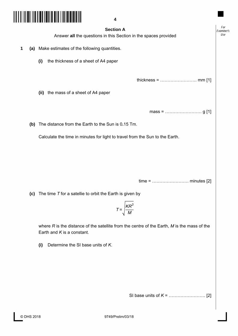
1 (a) Make estimates of the following quantities.
(i) the thickness of a sheet of A4 paper
thickness = ……………………. mm [1]
(ii) the mass of a sheet of A4 paper
mass = ……………………. g [1]
(b) The distance from the Earth to the Sun is 0.15 Tm.
Calculate the time in minutes for light to travel from the Sun to the Earth.
time = ……………………. minutes [2]
(c) The time T for a satellie to orbit the Earth is given by T= KR3
M
where R is the distance of the satellite from the centre of the Earth, M is the mass of the
Earth and K is a constant.
(i) Determine the SI base units of K.
SI base units of K = ……………………. [2]

5
© DHS 2018
9749/Prelim/03/18 [Turn over
For Examiner’s
Use (ii) Data for a particular satellite are given in Fig. 1.1
quantity measurement uncertainty
T 8.64 × 10⁴ s ± 0.50%
R 4.23 × 10⁷ m ± 1.0%
M 6.0 × 1024 kg ± 2.0%
Fig. 1.1
Express K with its associated uncertainty in SI units.
K = ……………………± ………………… SI units [3]
(iii) State the quantity which contributes the largest uncertainty in the value of K.
….…..…………………………………………………………………………………………
….…………………………………………………………………………………………... [1]
6
© DHS 2018 9749/Prelim/03/18
For Examiner’s
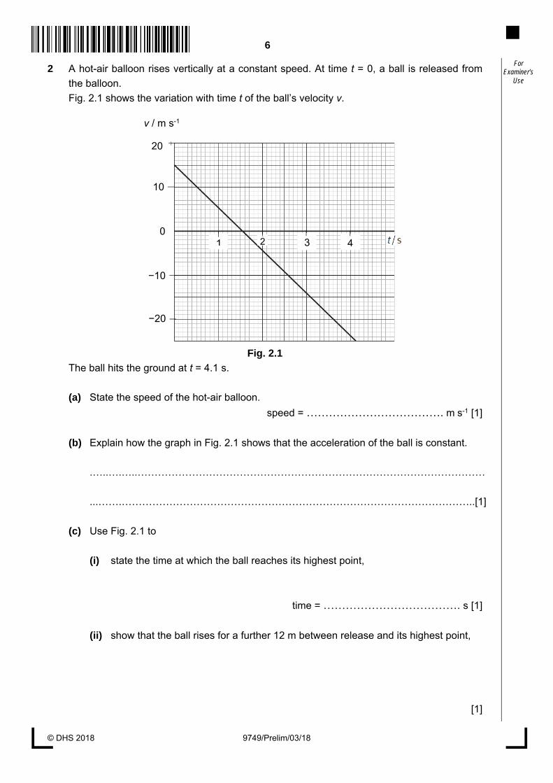
Use 2 A hot-air balloon rises vertically at a constant speed. At time t = 0, a ball is released from
the balloon.
Fig. 2.1 shows the variation with time t of the ball’s velocity v.
Fig. 2.1
The ball hits the ground at t = 4.1 s.
(a) State the speed of the hot-air balloon.
speed = ………………………………. m s-1 [1]
(b) Explain how the graph in Fig. 2.1 shows that the acceleration of the ball is constant.
.…..….…..…………………………………………………………………………………………
...…….…………………………………………………………………………………………..[1]
(c) Use Fig. 2.1 to
(i) state the time at which the ball reaches its highest point,
time = ………………………………. s [1]
(ii) show that the ball rises for a further 12 m between release and its highest point,
[1]
v / m s-1
20
10
−10
−20
0 1 3 42

7
© DHS 2018
9749/Prelim/03/18 [Turn over
For Examiner’s
Use (iii) determine the distance between the point of release of the ball and the ground.
distance = ………………………………. m [2]
(d) Describe the difference between displacement of the ball and the distance it travels.
.…..….…..…………………………………………………………………………………………
.…..….…..…………………………………………………………………………………………
...…….…………………………………………………………………………………………..[2]
(e) Sketch a new graph on Fig. 2.1 showing the variation with t of the ball’s velocity v if air
resistance is not negligible. Assume terminal velocity is attained by the ball before
hitting the ground. Label the new graph N. [2]
3 (a) (i) Define force.
….…..…………………………………………………………………………………………
….………………………………………………………………………………………….[1]
(ii) State Newton’s third law of motion.
….…..…………………………………………………………………………………………
….…..…………………………………………………………………………………………
….…………………………………………………………………………………………. [2]

8
© DHS 2018 9749/Prelim/03/18
For Examiner’s
Use (b) Fig. 3.1 shows the variation with time t of a jumping flea’s acceleration a. The
acceleration a is measured in unit of g, the acceleration of free fall. The flea of mass
210 µg jumped at nearly vertical take-off angle from ground.
Fig. 3.1
(i) Use Fig. 3.1 to
1. determine the maximum net external force acting on the jumping flea,
force = ………………………………. N [2]
2. estimate the maximum speed achieved by the flea.
speed = ………………………………. m s-1 [3]
(ii) State and explain whether linear momentum is conserved during the take-off of
the flea from the ground.
….…..…………………………………………………………………………………………
….…..…………………………………………………………………………………………
….…………………………………………………………………………………………..[2]
t / ms
a / g 150
100
50
0 0 0.5 1.0 1.5
9
© DHS 2018
9749/Prelim/03/18 [Turn over
For Examiner’s
Use 4 (a) Explain,
(i) what is meant by a radian,
….…..…………………………………………………………………………………………
….…..…………………………………………………………………………………………
….…………………………………………………………………………………………..[2]
(ii) why one complete revolution is equivalent to an angular displacement of 2π rad.
….…..…………………………………………………………………………………………
….…………………………………………………………………………………………..[1]
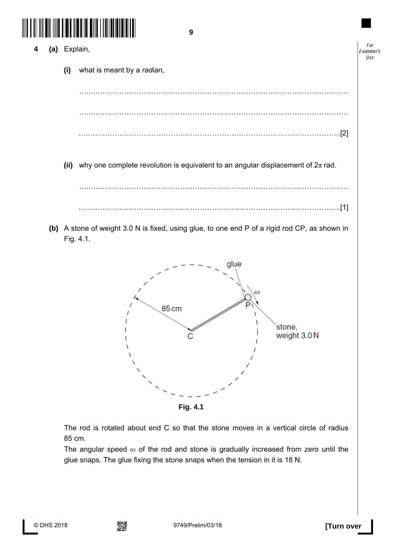
(b) A stone of weight 3.0 N is fixed, using glue, to one end P of a rigid rod CP, as shown in
Fig. 4.1.
Fig. 4.1
The rod is rotated about end C so that the stone moves in a vertical circle of radius
85 cm.
The angular speed ω of the rod and stone is gradually increased from zero until the
glue snaps. The glue fixing the stone snaps when the tension in it is 18 N.

10
© DHS 2018 9749/Prelim/03/18
For Examiner’s
Use For the position of the stone at which the glue snaps,
(i) mark with the letter S, the position of the stone on the dotted circle of Fig. 4.1 and
[1]
(ii) calculate the angular speed ω of the stone.
angular speed = ………………………………. rad s-1 [3]
(c) The same stone is now fixed on a string and made to travel along a horizontal circular
path, as shown in Fig. 4.2.
Fig. 4.2
11
© DHS 2018
9749/Prelim/03/18 [Turn over
For Examiner’s
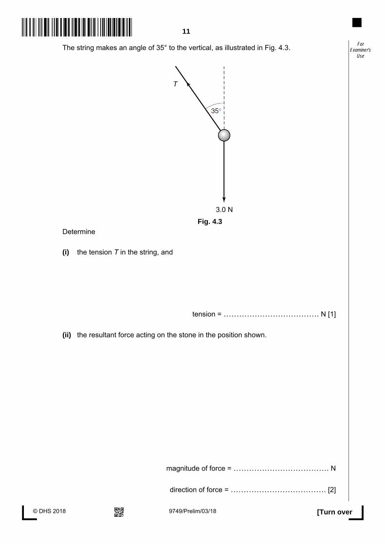
Use The string makes an angle of 35° to the vertical, as illustrated in Fig. 4.3.
Fig. 4.3
Determine
(i) the tension T in the string, and
tension = ………………………………. N [1]
(ii) the resultant force acting on the stone in the position shown.
magnitude of force = ………………………………. N
direction of force = ………………………………. [2]
T
3.0 N

12
© DHS 2018 9749/Prelim/03/18
For Examiner’s
Use 5 A cycle of changes in pressure, volume and temperature of gas inside a cylinder of a petrol
engine is illustrated in Fig. 5.1. The gas is assumed to be ideal.
Fig. 5.1 (not to scale)
There are four stages in the cycle.
stage description
A to B Rapid compression of the gaseous petrol/air mixture with the temperature rising
from 300 K at A and the pressure rising to 44 × 105 Pa at B.
B to C The petrol/air mixture is exploded, resulting in an almost instant rise in pressure.
At C the temperature has risen to 1960 K.
C to D Rapid expansion and cooling of the hot gases.
D to A Return to the starting point of the cycle.
(a) (i) State what is meant by an ideal gas.
….…..…………………………………………………………………………………………
….…..…………………………………………………………………………………………
….…………………………………………………………………………………………..[2]

13
© DHS 2018
9749/Prelim/03/18 [Turn over
For Examiner’s
Use (ii) Use the values in Fig. 5.1 to determine the number of moles present in the gases
in the cycle.
number of moles = ...................... moles [2]
(b) Complete the table in Fig. 5.2 showing the work done on the gas, the heat supplied to
the gas and the increase in the internal energy of the gas, during the four stages of one
cycle.
stage work done on gas /J
heat supplied to gas /J
increase in internal energy of gas
/ J A to B + 360
0
B to C + 670
C to D 0
− 810
D to A
[4]
(c) Explain qualitatively how molecular movement causes the fall in temperature of the gas
during the stage from C to D.
……….…..…………………………………………………………………………………………
……….…..…………………………………………………………………………………………
……….…..…………………………………………………………………………………………
……….…..…………………………………………………………………………………………
……….…………………………………………………………………………………………..[2]
Fig. 5.2

14
© DHS 2018 9749/Prelim/03/18
For Examiner’s
Use 6 (a) An alternating voltage of period 10 ms is being applied directly across a resistor of
5.0 Ω in a circuit. The variation with time t of voltage V is shown in Fig. 6.1.
Fig. 6.1
Calculate the steady voltage passing through the same resistor that would produce
an identical heating effect.
voltage = ...................................................... V [2]
(b) Explain why it is necessary to use high voltages for the efficient transmission of
electrical energy.
…..….…..…………………………………………………………………………………………
…..….…..…………………………………………………………………………………………
...…….…………………………………………………………………………………………..[2]
0 t / ms
V / V
2.0 4.0
6.0 8.0 10.0
-1.0
1.0
2.0
15
© DHS 2018
9749/Prelim/03/18 [Turn over
For Examiner’s
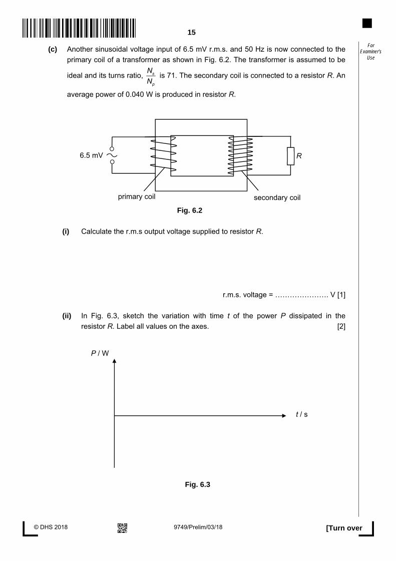
Use (c) Another sinusoidal voltage input of 6.5 mV r.m.s. and 50 Hz is now connected to the
primary coil of a transformer as shown in Fig. 6.2. The transformer is assumed to be
ideal and its turns ratio, s
p
N
N is 71. The secondary coil is connected to a resistor R. An
average power of 0.040 W is produced in resistor R.
Fig. 6.2
(i) Calculate the r.m.s output voltage supplied to resistor R.
r.m.s. voltage = …………………. V [1]
(ii) In Fig. 6.3, sketch the variation with time t of the power P dissipated in the
resistor R. Label all values on the axes. [2]
Fig. 6.3
P / W
t / s
6.5 mV R
primary coil secondary coil

16
© DHS 2018 9749/Prelim/03/18
For Examiner’s
Use (iii) An ideal diode is now connected to the secondary coil with resistor R as shown in
Fig. 6.4.
Fig. 6.4
Describe the variation with time of the
1. current flow through resistor R, and
….…..…………………………………………………………………………………………
….…..…………………………………………………………………………………………
….…………………………………………………………………………………………..[2]
2. voltage across resistor R.
….…..…………………………………………………………………………………………
….…………………………………………………………………………………………..[1]
6.5 mV R
primary coil secondary coil
diode
17
© DHS 2018
9749/Prelim/03/18 [Turn over
For Examiner’s
Use Section B
Answer one question from this Section in the spaces provided.
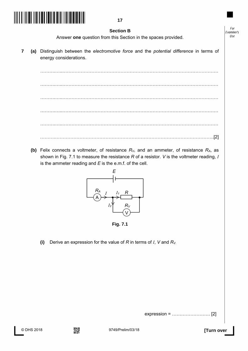
7 (a) Distinguish between the electromotive force and the potential difference in terms of
energy considerations.
……….…..…………………………………………………………………………………………
……….…..…………………………………………………………………………………………
……….…..…………………………………………………………………………………………
……….…..…………………………………………………………………………………………
……….…..…………………………………………………………………………………………
……….…………………………………………………………………………………………..[2]
(b) Felix connects a voltmeter, of resistance RV, and an ammeter, of resistance RA, as
shown in Fig. 7.1 to measure the resistance R of a resistor. V is the voltmeter reading, I is the ammeter reading and E is the e.m.f. of the cell.
Fig. 7.1
(i) Derive an expression for the value of R in terms of I, V and RV.
expression = ……………………. [2]
R I
E
A
V
I1
I2
RA
RV

18
© DHS 2018 9749/Prelim/03/18
For Examiner’s
Use (ii) Felix rearranges the circuit and connects the voltmeter and ammeter as shown in
Fig. 7.2 to measure the same resistance R.
Fig. 7.2
Derive an expression for the value of R in terms of I, V and RA.
expression = ……………………. [2]
(iii) Hence, suggest what the values of RV and RA should be such that the value of R is
equal to IV
.
….…..…………………………………………………………………………………………
….…..…………………………………………………………………………………………
….…………………………………………………………………………………………..[2]
A
V
R
E
I RA
RV

19
© DHS 2018
9749/Prelim/03/18 [Turn over
For Examiner’s
Use (c) Felix set ups a potentiometer circuit as shown in Fig. 7.3. The resistivity of wire AB is
1.4 × 10⁻⁶ Ω m, with a length of 1.1 m and a circular cross-section of radius 0.304 mm. The 2.2 V and 1.8 V cells have internal resistances of 0.30 Ω and 1.1 Ω respectively.
Fig. 7.3
(i) Determine the resistance of wire AB.
resistance = .................................... Ω [2]
(ii) 1. Calculate the length AC required to produce zero current in the galvanometer with switch K1 open and switch K2 closed.
length = .................................... cm [2]
K1
2.2 V
A
C
B
0.50 Ω
1.8 V
K2
1.2 Ω 1.1 Ω
0.30 Ω

20
© DHS 2018 9749/Prelim/03/18
For Examiner’s
Use 2. State and explain the change in length, if any, in your answer to (ii) 1., if
both switches K1 and K2 are open.
……….…..…………………………………………………………………………………
.…..…………………………………………………………………………………………
.…………………………………………………………………………………………..[2]
(iii) When both switches K1 and K2 are closed and there is zero current in the galvanometer, 1. calculate the power dissipated across wire AB and
power = .................................... W [2]
2. calculate the mean drift velocity v of the electron, if the number of electrons in one cm3 of wire AB is 1023.
v = .................................... m s-1 [1] (d) During his course of study in Physics, Felix comes across an electrical component.
The variation with potential difference V of current I for the component is shown in Fig. 7.4.

21
© DHS 2018
9749/Prelim/03/18 [Turn over
For Examiner’s
Use
Fig. 7.
(i) Use Fig. 7.4 to determine the resistance of the component at 3.4 V.
resistance = .................................... Ω [1]
(ii) Describe how the resistance of this component changes with the potential
difference applied across it from 0 V to 6.0 V.
…...…………………………………………………………………………………………
…...…………………………………………………………………………………………
…...…………………………………………………………………………………………
…..…………………………………………………………………………………….. [2]
V / V
0 2 4 8 6 10
I / A
0.5
1.0
1.5
0
Fig. 7.4

22
© DHS 2018 9749/Prelim/03/18
For Examiner’s
Use 8 (a) Fig. 8.1 shows an α-particle A as it approaches and passes by a stationary gold
nucleus N.
Fig. 8.1 (not to scale)
A second α-particle B has the same initial direction and energy as α-particle A. On Fig. 8.1, complete the path of α-particle B as it approaches and passes by the nucleus N. [2]
(b) An alpha particle has a speed of 1.30 × 10⁷ m s−1.
(i) Calculate the kinetic energy of the alpha particle.
kinetic energy = ....................................................... J [2]
(ii) The alpha particle is aimed directly at a gold nucleus which has a proton number of 79.
Calculate the distance of closest approach r.
r = ...................................................... m [3]
Fig. 8.1

23
© DHS 2018
9749/Prelim/03/18 [Turn over
For Examiner’s
Use (c) A radiation detector is placed close to a radioactive source. The detector does not
surround the source. Radiation is emitted in all directions and, as a result, the activity of the source and the measured count rate are different.
Suggest two other reasons why the activity and the measured count rate may be
different.
1. ……………………………………………………………………………………..................
……………………………………………………………………………………………………...
2. ……………………………………………………………………………………...................
………………………………………………………………………………………………….. [2]
(d) The variation with time t of the measured count rate in (c) is shown in Fig. 8.2.
Fig. 8.2
(i) State the feature of Fig. 8.2 that indicates the random nature of radioactive decay.
………………………………………………………………………………………..............
………………………………………………………………………………………......... [1]

24
© DHS 2018 9749/Prelim/03/18
For Examiner’s
Use (ii) Use Fig. 8.2 to determine the half-life of the radioactive isotope in the source.
half-life = ............................................... hours [4]
(e) The readings in (d) were obtained at room temperature. A second sample of this isotope is heated to a temperature of 500 °C. The initial count rate at time t = 0 is the same as that in (d). The variation with time t of the measured count rate from the heated source is determined. State, with a reason, the difference, if any, in 1. the half-life,
……………………………………………………………………………………………………...
……………………………………………………………………………………………………...
……………………………………………………………………………………………………...
2. the measured count rate for any specific time.
……………………………………………………………………………………………………...
……………………………………………………………………………………………………...
………………………………………………………………………………………………….. [3]

25
© DHS 2018
9749/Prelim/03/18 [Turn over
For Examiner’s
Use (f) A small volume of solution containing the radioactive isotope sodium-24 ( 24
11Na ) has an initial activity of 3.8 × 10⁴ Bq. Sodium-24, of half-life 15 hours, decays to form a stable daughter isotope.
All of the solution is poured into a container of water. After 36 hours, a sample of water of volume 5.0 cm3, taken from the container, is found to have an activity of 1.2 Bq.
Assuming that the solution of the radioactive isotope is distributed uniformly throughout the container of water, calculate the volume of water in the container.
volume = ................................................... cm3 [3]
END OF PAPER

26
© DHS 2018 9749/Prelim/03/18
For Examiner’s
Use
BLANK PAGE

Dunman High School 2018 Year 6 Prelim Exam H2 Physics Answers Paper 1 1 C 2 D 3 A 4 D 5 D 6 D 7 C 8 C 9 C 10 C 11 A 12 A 13 C 14 D 15 C 16 D 17 B 18 A 19 D 20 A 21 B 22 B 23 B 24 B 25 B 26 B 27 A 28 C 29 C 30 B
Paper 2 1 (a) (i) atmospheric pressure = 9.10 × 10⁴ Pa A1 (ii) (9.15 – 9.10) × 104 = ρm × 9.81 × (0.17 – 0.10) C1 ρm = 728 kg m-3 A1 (b) (i) pressure at top surface of cube = 9.135 × 10⁴ Pa (from graph) pressure at bottom surface of cube = 9.180 × 10⁴ Pa (from graph) C1 Upthrust = (9.180 – 9.135) × 104 × (0.051)2 C1 = 1.17 N A1 (ii) force = 4 – 1.17 = 2.83 N A1
(c) Remove the cube and check if spring returns to original length B1 (d) (i) free body diagram of upper ball, three forces: 1. weight, 2. horizontal force by wall on ball and 3. force by lower ball on upper ball. Angle is 45° between horizontal and the dotted line. So tan(45°) = (horizontal force) / (weight) C1 Horizontal force = weight = 1.67 N A1 OR taking moment about axis through point of contact between the balls: Same moment arm C1 Hence F = weight of ball = 1.67 N A1
(ii) F = 1.672+1.672 C1
= 2.36 N A1 2 (a) g = (6.1 ± 0.1) N m-1 C1 Force = mg = 6.1 × 20000 = (122 000 ± 2000) N A1
(b) F =m
r or g =
r C1
v = (6.1 × (8.2 × 10 = (7.1 ± 0.1) × 10 m s-1 A1
(c) (i) The gravitational potential at a point is defined as the work done per unit mass in bringing a small test mass from infinity to that point. B1
(ii) = GM
r=gr C1
= − (4.0 ± 0.1) × 107 J kg-1 A1 OR recognizes that this is the area under the graph from point to infinity B1 counting squares gives total area = − (4.0 ± 2.0) × 107 J kg-1 B1 3 (a) (i) g and r are constant, so a is proportional to x B1 negative sign shows a and x are in opposite direction B1
(ii) ω2 = g
r and ω =
2T
C1
ω2 = 9.81
0.28 = 35

T = 1.06 s M1 τ = 0.53 s A1 (b) Sketch: time period constant (or increases very slightly) B1 drawn lines always ‘inside’ given loops, up to given time duration B1
successive decrease in peak height B1
4 (a) (i) tanθ =
θ = 13o C1 d sinθ = nλ d = 2.82 x 10⁻⁶ m C1
number per metre = 1
d = 3.6 x 10⁵ m-1 A1
(ii) Lines further apart in second order, B1 Lines fainter in second order, B1 (if differences stated but without reference to the orders, max 1 mark)
(b) (i) P remains in same position B1 X and Y rotate through 90o B1
(ii) either screen not parallel to grating or grating not normal to incident light B1
5 (a) (i) a region in which a charge will experience a force B1 electric force exerted per unit positive charge placed at that point B1
(ii) E =Q
4εor2 = 5.2 ×
4 εo (0.25)2 B1
= 7.48 × 10⁴ A1 unit: N C−1 or V m−1 B1 (b) lines perpendicular to surface going into negative charge and leaving B1 positive charge for all charges neutral point indicated consistent with field lines B1
basic pattern correct (field lines near each charge are radial B1 spherically symmetrical) and fills rectangle
no crossing/joining of lines B1 max 3
6 (a) Magnetic field due to current in wire B is normal to the current in wire A, and pointing into plane of paper. By Fleming’s left hand rule, this causes a magnetic force to be exerted on wire A towards wire B. B1
X
Z Y

Based on Newton’s 3rd law, a magnetic force is also exerted on wire B by wire A which is of the same magnitude but opposite in direction, giving rise to an attractive force between both wires. B1
(b) (i) 0
2ABd
μπ
=I
74 10 (90)
2 (0.50)
ππ
−×=
= 3.6 × 10⁻⁵ T M1
2
0sin 90mv
Bqvr
= M1
mv
rBq
=27 3
5 19
(1.67 10 )(1.0 10 )
(3.6 10 )(1.6 10 )
−
− −
× ×=× ×
= 0.29 m A1
(ii) As proton is nearer to wire A, B increases (1
Br
α ) and radius decreases due to the
increasing magnetic force ( sinF Bqv θ= ). B1 Eventually at the nearest location to wire, the velocity of proton is parallel to wire, therefore force is directed away from wire, radius is smallest and pro ton is turned back. B1 B decreases further from wire A and radius increase due to decreasing F. B1
7 (a) (i) EM produced whenever charged particle is suddenly accelerated/ decelerated at the
metal target (and wavelength depends on magnitude of acceleration) M1 Electrons hitting the metal target have a range/distribution of accelerations A1
(ii) All kinetic energy of one electron given up in one collision to produce a single X-ray photon. B1
Minimum wavelength for maximum energy Or λmin = hc/Emax B1 So independent of target metals (only depend on accelerating voltage) A0
(b) (i) More likely (higher probability) for electrons at the next higher level to drop down to fill up the hole, so higher intensity for Kα A1
(ii) At low voltages, the energy of electrons (25 keV) is not sufficient B1 to knock electrons out of the inner shells of the tungsten atom B1 So no characteristic X-rays produced by de-excitation. A0
(c) hc
Eeλ
=34 8
19 11
(6.63 10 )(3 10 )
(1.6 10 )(6.6 10 )
−
− −
× ×=× ×
M1
= 1.88 × 10⁴ eV A1 8 (a) It is the number of trains arriving at a station per unit time. A1 (b) Aluminium alloy has high strength-to-weight ratio, thus reduces the amount of friction by
reducing the weight of the trains. It has high corrosion resistance. Aluminium’s natural passivation process in which a thin aluminium oxide layer forms when the metal is exposed to oxygen, reduces the possibility of further oxidation. A1
(c) (i)
Correct labelling of compression and tension A1
top of beam under compression
bottom of beam under tension
beam 2

(ii) Total normal reaction forces = (350 + 380) × 103 = 730 × 103 N A1
(iii) Total load column 1 has to take = 730 × 103 N A1 (iv) Total load ground has to take = (730 + 100) × 103 M1
= 830 × 103 N A1
(d) (i) Coordinate (4.3, 922) is treated as anomaly. Best fit line drawn through the rest of the seven points. A1
(ii) Gradient of line =1040 916
5.00 4.40
−−
M1
= 207 × 103 N m-2 A1
(iii) Factor of safety = 3
3
645 10
207 10
××
= 3.12 M1 Since factor of safety is greater than 2.9, it is safe. A1
(e) (i) Applied load = 3 22.5(207 10 ) ( )
2π× M1
= 1016 × 103 N A1
(ii) Total allowable weight of passengers = (1016 – 830) × 103 = 186 × 103 N A1
(iii) Total allowable number of passengers per car = 3186 10
( )60 10
××
M1
= 310 A1 (f) Number of passengers a car can take when train arrives at station
= 0.25 × 310 = 77.5 C1 Total number of passengers train can take = 77.5 × 6 = 465 M1
Longest time interval between train arrivals = 465
( )240
= 1.94 minutes A1
Paper 3 1 Consider a ream (500 sheets) of A4 papers (70 or 80 gsm). Thickness of 1 ream ≈ 5 cm, so thickness of one piece ≈ 0.01 cm ≈ 0.1 mm.
Area of A4 paper ≈ 200 x 300 = 60,000 mm2 = 0.06 m2 (a) (i) 0.05 – 0.15 mm A1
(ii) 4 – 5 g A1
(b) time = 0.15 x 10¹²
3.00 x 10⁸ C1
= 500 s = 8.3 min A1 (c) (i) SI units for T: s, R: m and M: kg (or seen in formula) C1
K = T2M
R3 units of K = s2kg
m3 A1
(ii) K = (86400 2(6 x 1024)
(4.23 x 10⁷)3 = 5.918 x 10¹¹ C1
K
K=2
0.5
100+3
1
100+
2
100 = 0.06 C1
ΔK = 0.355 x 10¹¹

K = (5.9 ± 0.4) x 1011 (SI units) A1 (incorrect % value, then max 1 mark) OR, Kmax = 6.283 x 10¹¹, ΔK = Kmax – K = 0.365 x 10¹¹
Kmin = 5.57 x 10¹¹, ΔK = 1
2 (Kmax – Kmin) = 0.355 x 10¹¹
(iii) R, as this has the largest fractional uncertainty. B1 2 (a) 15 m s-1 A1 (b) constant gradient (straight line graph) A1 (c) (i) 1.55 s A1 (ii) distance = area under the graph from 0 to 1.55 s =½ (15)(1.55) M1 = 11.6 m = 12 m A0 (iii) distance = ½ (25)(4.1 – 1.55) – 11.6 C1 = 31.875 – 11.6 = 20 m A1 (d) displacement is the straight line / minimum distance between the start and finish points
in that direction. B1 distance is the actual total path travelled by the ball. B1 (e) Smooth curve with decreasing gradient until zero at terminal velocity B1 gradient of the curve at x-intercept (0 m s–1) = gradient of the straight line and the curve crosses the x-axis before 1.55 s. B1 3 (a) (i) force is the rate of change of momentum B1 (ii) Force from B on body A is equal in magnitude but opposite in direction to force on B from A (forces act on different bodies) B1 Forces are of the same type B1 (b) (i) maximum force = (210 × 10-9) × (138 to 145) × 9.81 C1 = 2.84 × 10⁻⁴ to 2.99 × 10⁻⁴ N A1 (ii) Initial speed ~ 0 C1 Maximum speed = the area under the a – t graph C1 = 1.20 to 1.32 m s-1 A1 (iii) ground (and Earth) gain momentum M1 In equal and opposite to the change for the flea, so momentum conserved B1 4 (a) (i) angle subtended at centre of circle B1 (by) arc equal in length to the radius B1 (ii) arc = rθ and for one revolution, arc ≡ π (diameter) = π(2r) M1
so, θ = π(2r) / r = 2π A0 (b) (i) point S shown vertically below C B1
(ii) [(max) force / tension – weight ] provides the centripetal force C1 18 – 3 = m r ω2 = (3 / 9.81) (0.85) ω2 C1 ω = 7.6 rad s−1 A1
(c) (i) vertically no net force, T cos 35o = 3.0, T = 3.7 N A1 (ii) resultant is horizontal component of tension
3.7 sin 35o = 2.1 N A1 horizontally towards the left B1 5 (a) (i) obeys the law pV/T = constant or any two named gas laws M1 at all values of p, V and T A1 or two correct assumptions of kinetic theory of ideal gas B1

third correct assumption B1 (ii) (pV = nRT gives) (1.00 × 10⁵) (750 × 10-6) = n (8.31) (300) B1 n = 0.030 A1
(b)
work done on gas / J heat supplied o gas / J
increase in internal energy of gas / J
A to B +360 0 +360 & B to C 0 $ +670 +670 $ C to D -810 & 0 -810 D to A 0 @ -220 @ -220 #
&: first and third line correct B1 $: second line correct B1 #: −220 correct in right hand column B1 @: other two figures correct in last line B1
(c) the gas molecules bounce off the receding piston at lower speeds B1 there is a decrease in kinetic energy of the molecules B1
6 (a) +=
2 2
. . .
2 (0.002) 1 (0.002)
0.01r m sV M1
= 1.0 V A1
Steady voltage of 1 V will produce the same heating effect as Vr.m.s. of 1 V.
(b) Transmission of electrical energy at high voltage means that the current is low according to P = IV. B1 Power loss through joule heating (I2R) is hence lowered as less electrical energy is dissipated as heat in the cables of resistance R. B1
(c) (i) s s
p p
V N
V N=
Vs = 71 × 6.5 × 10-3 = 0.46 V A1
(ii)
Correct shape. B1 Correct labelling of values. B1
(iii) 1. In the forward biased direction, the diode has no resistance. Current flows
downwards through resistor R. A1
0.080
0.020
P / W
t / s 0
In the reverse biased direction, diode has infinite resistance. There is no current flowing through resistor R. A1
2. In the forward biased direction, there is a half-wave sinusoidal voltage output across resistor R, having the same frequency as that of the input voltage. In the reverse biased direction, there is no voltage output across resistor R. A1
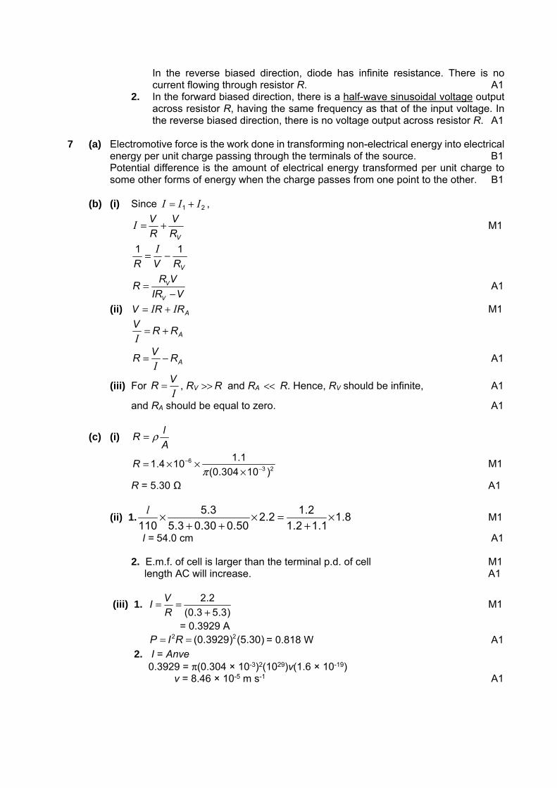
7 (a) Electromotive force is the work done in transforming non-electrical energy into electrical
energy per unit charge passing through the terminals of the source. B1 Potential difference is the amount of electrical energy transformed per unit charge to
some other forms of energy when the charge passes from one point to the other. B1 (b) (i) Since 21 III += ,
VR
V
R
V +=I M1
VRVR
11 −= I
V
V
R VR
IR V=
− A1
(ii) ARRV II += M1
ARRV +=I
ARV
R −=I
A1
(iii) For IV
R = , RV >> R and RA << R. Hence, RV should be infinite, A1
and RA should be equal to zero. A1
(c) (i) A
lR ρ=
63 2
1.11.4 10
(0.304 10 )R
π−
−= × ××
M1
R = 5.30 Ω A1
(ii) 1.5.3 1.2
2.2 1.8110 5.3 0.30 0.50 1.2 1.1
× × = ×+ + +
l M1
l = 54.0 cm A1 2. E.m.f. of cell is larger than the terminal p.d. of cell M1
length AC will increase. A1
(iii) 1. 2.2
(0.3 5.3)
VI
R= =
+ M1
= 0.3929 A 2 2(0.3929) (5.30)P I R= = = 0.818 W A1 2. I = Anve 0.3929 = π(0.304 × 10⁻³)2(1029)v(1.6 × 10⁻¹⁹) v = 8.46 × 10⁻⁵ m s-1 A1

(d) (i) R = 3.4
1.125= 3.02 Ω A1
(ii) As the potential difference (p.d.) increases from 0 V to 3.4 V, the ratio of V to I
decreases, hence resistance decreases. B1 As the p.d. increases from 3.4 V to 6.0 V, the ratio of V to I increases. Hence,
resistance increases during this interval. B1 8 (a) smaller deviation (not zero deviation) M1 acceptable path wrt position of N A1
(b) (i) mass of alpha particle = 4 × 1.66 × 10−27 kg B1 (kinetic energy = 0.5 × 4 × 1.66 × 10−27 × (1.30 × 107)2 J A1
(ii) all the kinetic energy becomes electrical potential energy B1 5.61 × 10−13 = QαQAu / 4πε0r = (2e) (79e) / 4πε0r C1 r = 6.48 × 10⁻¹⁴ m A1 (c)
• emission from radioactive daughter products • self-absorption in source • absorption in air before reaching detector • detector not sensitive to all radiations • window of detector may absorb some radiation • background radiation
Any two points. B2
(d) (i) curve is not smooth or curve fluctuates/curve is jagged B1 (ii) clear evidence of allowance for background B1 half-life determined at least twice B1 half-life = 1.5 hours A2 (2 marks if in range 1.4 – 1.6; 1 mark if 1.6 < half-life ≤ 2.0) (e) 1. half-life: no change M1 because decay is spontaneous/independent of environment A1
2. count rate (likely to be or could be) different / is random / cannot be predicted B1
(f) activity = (3.8 × 10⁴) e(−ln 2 / 15)(36) C1 or activity = (3.8 × 10⁴) [1 / 22.4] (C1) = 7200 Bq A1 volume = (7200 / 1.2) × 5.0 = 3.0 × 104 cm3 A1 or activity of 5.0 cm3 = 1.2 × 22.4 (C1) = 6.3336 Bq (C1) volume = (3.8 × 10⁴ / 6.3336) × 5.0 = 3.0 × 104 cm3 (A1) Paper 4
Qns Skills Assessed and Marking Instructions M 1 b (ii) Value of d to nearest mm. 1
(ii) Evidence of repeated measurements of d.
1

(iii)
Absolute uncertainty in the range of 2 mm to 10 mm (1 s.f.). Percentage uncertainty calculated correctly. Percentage uncertainty in 2/3 s.f.
1
c (ii) Value of h to nearest mm. 1
Value of t in s and must be between 0.1 to 10 s 1
d Terminal velocity calculated correctly with unit
1
f Measurement and record of second value of d2. Value of second t (t2). Correct calculation of second v2. Quality of result: smaller d gives greater v. Determination of a constant of proportionality k (two values of k where k = vd) Draw conclusion based on the calculated values of k. Candidate must test against a specified criterion (e.g. 20% difference in values of k, with reference to the uncertainty calculated (b)(iii)).
1
1
1
1
1
g Terminal velocity may not be reached at short distance, - Increase height - Measure velocity at two points to check terminal velocity reached
Much faster velocity
- Use light gate to trigger stopwatch to eliminate human reaction error in timing
Take more readings and plot a graph to check relationship Or other valid improvement. Max: 3 marks.
1 1
1
1
Qns Skills Assessed and Marking Instructions M 2 a (iii) Value of θ to the nearest degree, with unit. 1
(iv) cos θ calculated correctly 1
(v)
Answer must relate sf in θ to sf in cos θ Do not allow vague answers that are given in terms of ‘raw data’
1
b (iii) Value of T with unit. The number of oscillations n taken such that n T1 > 10 s. Evidence of repeats.
1
1
c Value of k calculated correctly with correct unit, s-4. 1
d Measurement of L, the value should be in the range 40 cm ± 2 cm. 1
Correct method of working to give a value of g in the range 7.5 to 12.5 m s-2. 1
Correct unit of g
1

Qns Skills Assessed and Marking Instructions M 3 b (i) V and I recorded with unit.
1
(ii) Resistance of LDR calculated correctly And greater than 1 kΩ and less than 100 kΩ.
1
c
• Award 2 marks if student has successfully collected 6 or more sets of data (V, I) without assistance/intervention. 5 sets one mark. 4 or fewer sets zero mark.
• Deduct 1 mark if minor help from supervisor, deduct 2 if major help.
• Deduct 1 mark if wrong trend in I (or R).
C1 2
Each column heading must contain a quantity and a unit where appropriate. Ignore units in the body of the table. There must be some distinguishing mark between the quantity and the unit i.e. solidus is expected, I/mA. Allow lg(R), lg(R/Ω) but not lgR/Ω.
C2 1
Consistency of raw readings, I in mA and V in V only. C3 1
For each calculated value of lg, the number of d.p in calculated value should reflect the number of s.f. in the raw readings. All values must be given to an appropriate number of s.f. for this mark to be awarded.
C4 1
Correctly calculated values of R, lg(R) and lg(N). C5 1
d Linearising equation and deriving expressions that equate e.g. gradient to b and y-intercept to lg(a), lg(R) = lg(a)+b lg(N).
D1 1
Graph: Sensible scales must be used. Awkward scales (e.g. 3:10) are not allowed. Scales must be chosen so that the plotted points occupy at least half the graph grid in both x and y directions. Scales must be labeled with the quantity which is being plotted.
D2 1
All observations must be correctly plotted. Work to an accuracy of half a small square. Diameter of the plotted point must be less than half the small square.
D3 1
Line of best fit – judge by scatter of points about the candidate's line. There must be a fair scatter of points either side of the line. Allow only one anomalous point if clearly indicated (i.e. labelled or circled) by the student.
D4 1
Gradient – the hypotenuse of the ∆ must be greater than half the length of the drawn line. Read-offs must be accurate to half a small square. Check for ∆y/∆x (i.e. do not allow ∆x/∆y). The value must be negative.
D5 1
y-intercept – must be read off to nearest half a small square or determined from y=mx+c using a point on the line.
D6 1
Values of a and b calculated correctly D7 1
Unit of a, no units of b D8 1
4
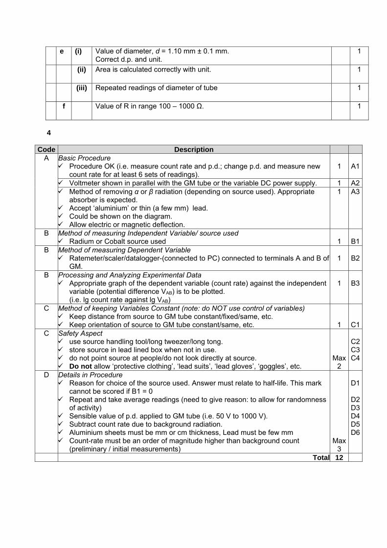
Code Description A Basic Procedure
Procedure OK (i.e. measure count rate and p.d.; change p.d. and measure new count rate for at least 6 sets of readings).
1
A1
Voltmeter shown in parallel with the GM tube or the variable DC power supply. 1 A2 Method of removing α or β radiation (depending on source used). Appropriate
absorber is expected. Accept ‘aluminium’ or thin (a few mm) lead. Could be shown on the diagram. Allow electric or magnetic deflection.
1 A3
B Method of measuring Independent Variable/ source used Radium or Cobalt source used
1
B1
B Method of measuring Dependent Variable Ratemeter/scaler/datalogger-(connected to PC) connected to terminals A and B of
GM.
1
B2
B Processing and Analyzing Experimental Data Appropriate graph of the dependent variable (count rate) against the independent
variable (potential difference VAB) is to be plotted. (i.e. lg count rate against lg VAB)
1
B3
C Method of keeping Variables Constant (note: do NOT use control of variables) Keep distance from source to GM tube constant/fixed/same, etc. Keep orientation of source to GM tube constant/same, etc. 1
C1C Safety Aspect
use source handling tool/long tweezer/long tong. store source in lead lined box when not in use. do not point source at people/do not look directly at source. Do not allow ‘protective clothing’, ‘lead suits’, ‘lead gloves’, ‘goggles’, etc.
Max 2
C2C3C4
D Details in Procedure Reason for choice of the source used. Answer must relate to half-life. This mark
cannot be scored if B1 = 0 Repeat and take average readings (need to give reason: to allow for randomness
of activity) Sensible value of p.d. applied to GM tube (i.e. 50 V to 1000 V). Subtract count rate due to background radiation. Aluminium sheets must be mm or cm thickness, Lead must be few mm Count-rate must be an order of magnitude higher than background count
(preliminary / initial measurements) Max
3
D1
D2D3D4D5D6
Total 12
e (i) Value of diameter, d = 1.10 mm ± 0.1 mm. Correct d.p. and unit.
1
(ii) Area is calculated correctly with unit. 1
(iii) Repeated readings of diameter of tube 1
f Value of R in range 100 – 1000 Ω. 1

Aim: To investigate how the count rate due to γ-radiation depends on the potential difference VAB
Independent variable: Potential difference VAB Dependent variable: count rate due to γ-radiation
Procedure
1. Set up apparatus as shown in the diagram above. 2. Use the Cobalt-60 source source
a. Half-life is sufficiently long to avoid a large change in activity during the experiment and is approximately constant
b. Does not emit α-radiation, which is highly ionizing and hence toxic on close contact
c. Place in front of the thin mica window at about 3 cm away. d. Place an aluminium plate of a few centimetre thickness between source and
window to prevent α- and β- radiation from reaching the detector 3. Vary the potential difference supplied across points A and B
a. Connect the output ends of a variable DC voltage supply to points A and B b. Obtain the supplied potential difference by reading off the output settings.
4. Measure the count rate across points A and B a. Connect the rate meter to points A and B. b. Read off the count rate from the display of the rate meter, C.
5. Repeat steps 3 and 4 for different outputs of potential differences, each time performing averaging for each potential difference.
Control variables:
1. Distance between source and mica window a. Secure the 2 in position using retort stands
2. Activity of source a. Keep to the same source so that the age of the source is approximately constant
Analysis
1. Assume C = kVABn ,
where C is the count rate measured by the rate meter, VAB the potential difference between points A and B, k and n are constants.
2. Taking logarithm on both sides of the equation, we obtain lg C = lg k + n lg VAB 3. The graph of against will be a straight line graph with y-intercept and gradient n if the
equation is valid. Safety
1. Handle the source with long tweezer. 2. Store source in lead-lined box when not in use.
thin mica window
wire anode cylinder cathode
gas at low pressure
A
B
variable DC voltage supply
source
Aluminium plate (few cm)
rate meter