janus trx - reer.it · the j trx safety light curtain is a multi-beam opto-electronic safety system...
TRANSCRIPT

PHOTOELECTRIC SAFETY BARRIER
JANUS TRX
IINNSSTTAALLLLAAZZIIOONNEE,, UUSSOO EE MMAANNUUTTEENNZZIIOONNEE
IINNSSTTAALLLLAATTIIOONN,, UUSSEE AANNDD MMAAIINNTTEENNAANNCCEE
IINNSSTTAALLLLAATTIIOONN,, UUTTIILLIISSAATTIIOONN EETT MMAAIINNTTEENNAANNCCEE
IINNSSTTAALLLLAATTIIOONN,, BBEEDDIIEENNUUNNGG UUNNDD WWAARRTTUUNNGG
IINNSSTTAALLAACCIIÓÓNN,, UUSSOO YY MMAANNTTEENNIIMMIIEENNTTOO
www.reer.it

8540568 - 22/03/2016 - Rev.5 1
PHOTOELECTRIC SAFETY
BARRIER
JANUS TRX
INSTALLATION USE AND MAINTENANCE
INDICE
INTRODUCTION ................................................................................................................... 2
PRINCIPLE OF OPERATION ................................................................................................ 3
INSTALLATION ..................................................................................................................... 5
POSITION ......................................................................................................................................6 MULTIPLE SYSTEMS ...................................................................................................................6 SAFETY DISTANCE CALCULATION ............................................................................................7 VERTICAL POSITION OF THE BARRIER ....................................................................................8 ELECTRICAL CONNECTIONS .....................................................................................................8 EXTERNAL CONNECTION ...........................................................................................................9 DISTANCE BETWEEN REFLECTING SURFACES .................................................................. 10 MOUNTING AND OPTICAL ALIGNMENT ................................................................................. 12
OPERATION AND TECHNICAL DATA ................................................................................ 13
LIGHT SIGNALS ......................................................................................................................... 13 CONFIGURATION AND OPERATION MODES ......................................................................... 15 K1/K2 EXTERNAL CONTACTORS CONNECTION ................................................................... 18 OUTPUT STATUS ...................................................................................................................... 18 TECHNICAL SPECIFICATIONS ................................................................................................. 19
DIMENSIONS ...................................................................................................................... 20
CHECKOUTS AND MAINTENANCE ................................................................................... 21
TROUBLESHOOTING ................................................................................................................ 22
SPARE PARTS .................................................................................................................... 24
GUARANTEE ...................................................................................................................... 25

2 8540568 - 22/03/2016 - Rev.5
This symbol stands by a very important warning concerning the safety of persons. Its non-observance can cause a very serious risk for the exposed personnel.
INTRODUCTION
The J TRX safety light curtain is a multi-beam opto-electronic safety system of the Type 4 category of electro-sensitive devices in accordance with IEC61496-1,2 EN61496-1, for the protection of persons exposed to dangerous machines or plants.
This light curtain consists of an active element J TRX E/R (containing the emitter and the receiver) and a passive element TRX RR, consisting of pre-aligned reflectors, capable of reflecting the strip of infrared light (Figure 1, 2 and 3).
2-beams models (distance 500mm), 3-beams models (distance 400mm) and 4-beams models (distance 300mm) are provided (according to the European Standard ISO 13855).
A diagnostic display available on the active element provides the necessary informations for a correct use of the device and the valuation of the possible operation failures.
JANUS TRX is ideal for protecting:
Automatic palletizing/depalletizing systems, packing and packaging machines, metal, wood, marble and glass tool machines, materials handling.
If necessary, for any safety-related problems contact the competent safety authorities or industrial associations in the country of use.
For applications in the food industry, please contact the manufacturer to ensure that the barrier contains materials that are compatible with the chemical agents utilized.
The protective function of the optoelectronic devices is not effective in the following cases:
If the machine stopping control cannot be actuated electrically and it is not possible to stop all dangerous machine movements immediately and at any time during the operating cycle.
If the machine generates dangerous situations due to material being expelled or falling from overhead.

8540568 - 22/03/2016 - Rev.5 3
PRINCIPLE OF OPERATION
Figure 1 shows the MI/ML/MT TRX way of operation :
The active element M TRX E/R contains the emitter and the receiver units; the emitted infrared beam, correctly reflected by the pre-aligned deflection mirrors of the passive element TRX RR, is received by the receiver of the M TRX E/R.
With the protected area clear, the two PNP outputs of the active elements are in ON condition (24VDC) and guarantee the normal operation of the connected machine.
When an object interrupts the infrared beams, the TRX PNP outputs are de-energized (OFF condition - 0VDC). This condition permits to stop the moving body of the machine (thanks to a specific stopping circuit).
ACTIVE ELEMENT
EMITTER
RECEIVER
Figure 1 - J TRX with 2 beams
PASSIVE ELEMENT
1° MIRROR 2° MIRROR
ACTIVE ELEMENT
RECEIVER1
EMITTER1 EMITTER2
RECEIVER2
Figure 2 - J TRX with 3 beams
PASSIVE ELEMENT
1° MIRROR 2° MIRROR 3° MIRROR 4° MIRROR
4 8540568 - 22/03/2016 - Rev.5
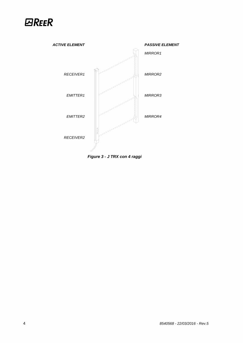
ACTIVE ELEMENT
RECEIVER1
EMITTER1
EMITTER2
RECEIVER2
Figure 3 - J TRX con 4 raggi
PASSIVE ELEMENT
MIRROR1 MIRROR2 MIRROR3 MIRROR4

8540568 - 22/03/2016 - Rev.5 5
INSTALLATION
Before installing the JANUS TRX safety system, make sure that:
The safety system is only used as a stopping device and not as a machine control device.
The machine control can be actuated electrically.
All dangerous machine movements can be interrupted immediately. In particular, the machine stopping times must be known and, if necessary, measured.
The machine does not generate dangerous situations due to materials projecting or falling from overhead; if that is not the case, additional mechanical guards must be installed.
The minimum dimensions of the object that must be intercepted are greater than or equal to the resolution of the JANUS TRX.
Knowledge of the shape and dimensions of the dangerous area enables the width and height of the relative access area to be calculated.
Compare these dimensions with the maximum working range and the height of the protected area in relation to the JANUS TRX.
The general instructions set out below must be taken into consideration before placing the safety device in position.
Make sure that the temperature of the environment in which the system is to be installed is compatible with the temperature parameters contained in the technical data sheet.
Do not install the active unit close to bright or high-intensity flashing light sources.
Certain environmental conditions may affect the monitoring capacity of the photoelectric devices. In order to assure correct operation of equipment in places that may be subject to fog, rain, smoke or dust, the appropriate correction factors Cf should be applied to the maximum working range values. In these cases: where Pu and Pm are, respectively, the working and maximum range in meters.
Pu = Pm x Cf

6 8540568 - 22/03/2016 - Rev.5
The recommended Cf factors are shown in the table below:
ENVIRONMENTAL CONDITION CORRECTION FACTOR Cf
Fog 0.25
Steam 0.50
Dust 0.50
Dense fumes 0.25
If the device is installed in places that are subject to sudden changes in temperature, the appropriate precautions must be taken in order to prevent the formation of condensation on the lenses, which could have an adverse effect on monitoring.
POSITION
The active J TRX E/R and passive elements J TRX RR must be positioned in such a way that the access to the dangerous zone from overhead, bottom and from the opposite sides is impossible without intercepting at least one of the two optical beams.
Figure 4
MULTIPLE SYSTEMS
JANUS TRX is composed of one active and one reflecting element; when more than one JANUS TRX system is used, precaution must be taken to avoid optical interference between them.
We recommend to interpose between two adjacent systems, opportune NOT TRANSPARENT surfaces to stop the passage of the infrared beam.
WARNING
To reach the perfect JANUS TRX installation, position both the units as showed in Figure 4
(REER labels in the same side)
FR
ON
T W
IND
OW
JA
NU
S
JA
NU
S

8540568 - 22/03/2016 - Rev.5 7
SAFETY DISTANCE CALCULATION
The barrier must be installed at a distance that is greater than or equal to the minimum safety distance S, so that a dangerous point can only be reached after all hazardous machine movements have stopped (Figure 3).
According to European standard EN999, the minimum safety distance S must be calculated using the following formula:
S = K (t1 + t2) + C where:
S minimum safety distance mm
K approach speed of object to the dangerous area mm/sec
t1 response time of the safety barrier in seconds sec
t2 machine response time, in seconds, meaning the time
required for the machine to interrupt the dangerous movement following transmission of the stop signal
sec
c additional distance mm
The non-observance of the correct safety distance reduces or cancels the protective action of the light curtain.
If the position of the barrier does not prevent the operator from having access to the dangerous area without being detected, additional mechanical guards must be installed to complete the system.
S=Safety distance
Figure 5
HAZARDOUS
MACHINE
S
PASSIVE
ELEMENT
ACTIVE
ELEMENT
MECHANICAL
PROTECTIONS

8 8540568 - 22/03/2016 - Rev.5
VERTICAL POSITION OF THE BARRIER
These models are suitable for the protection of the entire body and must not be used to protect arms or legs.
The minimum safety distance S is calculated according to the following formula:
S = 1600 (t1 + t2) + 850
The recommended height H from the reference surface G (ground) is as follows:
Figure 6
MODEL BEAMS Reccomended Height H (mm)
J 2B TRX E/R J 3B TRX E/R J 4B TRX E/R
2 3 4
400 – 900 300 – 700 – 1100
300 – 600 – 900 - 1200
ELECTRICAL CONNECTIONS
WARNINGS
Before making the electrical connections, make sure that the supply voltage complies with the one specified in the technical data sheet.
Janus TRX must be supplied with 24Vdc±20% power supply that guarantee safe isolation from main voltage (PELV).
The external power supply must comply with the standard EN 60204-1 (Chapter 6.4).
The electrical connections must be made according to the diagrams in this manual. In particular, do not connect other devices to the connectors of the active unit.
To guarantee reliability of operation, when using a diode jumper supply unit, its output capacity must be at least 2000µF for each absorbed A.
safety barrier
point of danger
direction of approach
reference plane

8540568 - 22/03/2016 - Rev.5 9
Connector pins.
Figure 7
EXTERNAL CONNECTION
PIN COLOR NAME TYPE DESCRIPTION OPERATION
2 Brown 24VDC - 24VDC power supply -
7 Blue 0VDC - 0VDC -
8 Red PE - Ground connection -
1 White OSSD1 OUTPUT Safety static outputs PNP active high
3 Green OSSD2 OUTPUT
5 Grey EXT_SEL_A INPUT Barrier configuration According the normative
EN61131-2 (ref. Table 2 and Table 3)
6 Pink EXT_SEL_B INPUT
4 Yellow EXT_K1_K2 INPUT Feedback external
contactors
Table 1
Warnings regarding the connection cables
For connections over 50m long, use cables with a cross-section area of 1 mm2.
The power supply to the barrier should be kept separate from that to other electric power equipment (electric motors, inverters, frequency converters) or other sources of disturbance.
Connect the active element to the ground output.
The connection cables must follow a different route to that of the other power cables.

10 8540568 - 22/03/2016 - Rev.5
DISTANCE BETWEEN REFLECTING SURFACES
The presence of reflecting surfaces in proximity of the photoelectric barrier may generate spurious reflections that prevent monitoring. With reference to Figure 8, object A is not detected because surface S reflects the beam and closes the optical path between the active and passive elements.
A minimum distance d must therefore be maintained between any reflecting surfaces and the protected area. The minimum distance d must be calculated according to the distance l between the active and passive unit, considering that the angle of projection and reception is 4°.
Figure 8
Figure 9 illustrates the values for the minimum distance d that must be maintained when the distance l between the active and passive elements is changed.

8540568 - 22/03/2016 - Rev.5 11
Figure 9
After installing the system, check whether any reflecting surfaces intercept the beams, first in the centre and then in the vicinity of the active unit.
During these operations, the red LED on the active elements should never, for any reason, switch off.

12 8540568 - 22/03/2016 - Rev.5
MOUNTING AND OPTICAL ALIGNMENT
The active element J TRX E/R and the the passive element J TRX RR must be mounted the first in front of the other with the same (or less) distance showed in the technical data.
Using the fastening brackets and inserts (available on request) fix the active element J TRX E/R and the passive element J TRX RR aligned and parallel.
The fastening inserts can be located in the rear or in the side spline of the units, depending on the dimensions and shape of the machine rest (Figure 10). The bracket supplied with the barrier must be fixed in the vertical center of the columns.
The perfect alignment between the two units is essential for the correct barrier operation; the control of the signal leds makes this function easier.
Figure 10
Place the optical axis of the photoemitter and photoreceiver on the same axis of the reflecting mirrors of the passive element.
Hold the passive element and move J TRX E/R to find the area within which the green led stays on, then position the first beam (the one close to the indicator leds) in the centre of this area.
Lock the two units in place.
During these operations it may be useful to check the orange weak signal LED on the passive element. Upon completion of alignment, this LED must be off.
If the active element is assembled in areas that are subject to strong vibrations, the use of vibration-damping supports is recommended, in order to prevent circuit malfunctions.

8540568 - 22/03/2016 - Rev.5 13
OPERATION AND TECHNICAL DATA
LIGHT SIGNALS
ACTIVE ELEMENT SIGNALS
At power-on, for a period of 5 seconds, the display will show the number "8" and all the leds will be ON. In the next 10 seconds, the display and the leds will show the configuration selected. At initial power-on after installation, always check the accuracy of these settings very carefully. This check is also indispensable in all cases of malfunctioning (ref. "TROUBLESHOOTING").
During display of the configuration, the display will show the letter "C" while during normal operation, a hyphen "-" will be displayed (ref. Figure 11).
Initial display
Figure 11
LED NORMAL OPERATION
COLOR (LED ON) (LED OFF)
Weak (1) - - ORANGE
Break (2) OSSD outputs set to OFF - RED
Guard (3) - - GREEN
Clear (4) CLEAR - - YELLOW
MAN/AUTO Manual functioning
mode enabled Automatic functioning mode
enabled YELLOW
EN EDM Control of feedback external relays
enabled Control of feedback external
relays disabled YELLOW
(1) Weak signal from the emitter
(2) Barrier occupied - output disabled
(3) Barrier free - output enabled
(4) Barrier free - output disabled - Waiting for restart
The flashing led together with the C and F letters indicates the incorrect type of configuration.
2 1
3 4

14 8540568 - 22/03/2016 - Rev.5
Normal display
LED NORMAL OPERATION
COLOR (LED ON) (LED OFF)
Weak (1) Weak signal received Signal received OK ORANGE
Break (2) Light curtain occupied, OSSD outputs set OFF
- RED
Guard (3) Light curtain clear,
OSSD outputs set ON - GREEN
Clear (4) CLEAR Light curtain clear, OSSD outputs set
OFF (the receiver is waiting for a Restart signal)
- YELLOW
(1) Weak signal from the emitter
(2) Barrier occupied - output disabled
(3) Barrier free - output enabled
(4) Barrier free - output disabled - Waiting for restart
In case of fault, only the red led will remain ON and the display will show a flashing "C" or “F” followed by the fault code (ref. TROUBLESHOOTING paragraph).

8540568 - 22/03/2016 - Rev.5 15
CONFIGURATION AND OPERATION MODES
The JANUS TRX operation mode is selected realizing appropriate connections on the M12 8 poles of the active element (Table 1 and Table 2).
AUTOMATICO MODE
In this operation mode the OSSD1 and OSSD2 safety outputs follow the barrier status :
with proteceted area clear, the safety outputs are active.
with proteceted area intercepted, the safety outputs are disabled.
CONNECTION OPERATION MODE
EXT_SEL_A (PIN 5)
connected to : ext_OSSD1 (PIN 1)
EXT_SEL_B (PIN 6)
connected to : ext_OSSD2 (PIN 3)
EXT_K1_K2 (PIN 4)
connected to : 0VDC
AUTOMATIC without K1-K2 feedback
EXT_SEL_A (PIN 5)
connected to : ext_OSSD2 (PIN 3)
EXT_SEL_B (PIN 6)
connected to : ext_OSSD1 (PIN 1)
EXT_K1_K2 (PIN 4)
connected to : 24VDC (through series of contatcts
N.C. of external relays)
AUTOMATIC with K1-K2 feedback
Table 2
Figure 12
Example of connection of TRX barrier in AUTOMATIC mode with feedback K1K2

16 8540568 - 22/03/2016 - Rev.5
Figure 13 Example of connection of TRX barrier in AUTOMATIC mode without feedback K1K2
MANUAL MODE
In this operating mode the safety outputs OSSD1 and OSSD2 are activated (+24VDC) only if the protected area is free and after the reception of the RESTART signal, using a push button or thank to an appropriate control on the SEL_A or SEL_B input (ref.Table 3).
After an interception of the protected area, the safety outputs will be de-activated. To re-activate them it will be necessary to repeat the sequence described above.
The RESTART command is active with a voltage of +24VDC.
The minimum duration of the RESTART command is 400ms.
Use of manual mode (start/restart interlock activated) is compulsory if the safety device controls an opening to protect a danger area and a person, after passing through the opening, may remain in the danger area without being detected (use as 'trip device' according to IEC 61496). Failure to comply with this rule may result in very serious hazards for the persons exposed.
CONNECTION OPERATION MODE
EXT_SEL_A (PIN 5)
connected to : 24VDC (PIN 2)
EXT_SEL_B (PIN 6)
connected to : 24VDC (PIN 2)
(through the RESTART pushbutton)
EXT_K1_K2 (PIN 4)
connected to : 0VDC
MANUALE senza feedback K1-K2
EXT_SEL_A (PIN 5)
connected to : 24VDC (PIN 2)
(through the RESTART pushbutton)
EXT_SEL_B (PIN 6)
connected to : 24VDC (PIN 2)
EXT_K1_K2 (PIN 4)
connected to : 24VDC (through series of contatcts
N.C. of external relays)
MANUALE con feedback K1-K2
Table 3

8540568 - 22/03/2016 - Rev.5 17
Figure 14
Example of connection of TRX barrier in MANUAL mode with feedback K1K2
Figure 15 Example of connection of TRX barrier in MANUAL mode without feedback K1K2

18 8540568 - 22/03/2016 - Rev.5
K1/K2 EXTERNAL CONTACTORS CONNECTION
In every operating mode is activable the K1/K2 external contactors feedback.
If you want to use this check, connect the pin 4 of 8 poles M12 connector with the power supply (+24VDC) through the series of N.C. contacts (feedback) of external contactors.
OUTPUT STATUS
Janus TRX features two static PNP outputs on the active element, the status of which depends on the condition of the protected area.
The maximum load allowed is 500mA at 24VDC, which corresponds to a resistive load of
48. Maxim load capacity corresponds to 2.2F. The meaning of the status of outputs is defined in the table below. Any short circuit between outputs or between outputs and 24VDC or 0VDC power supplies is detected by the barrier.
NAME OF SIGNAL CONDITION MEANING
OSSD1 24VDC Condizione di barriera libera.
OSSD2
OSSD1 0VDC
Condizione di barriera occupata o guasto riscontrato OSSD2
Table 4
In the protected area clear condition, the active element supplies a voltage of 24 VDC on both outputs. The required load must therefore be connected between the output terminals and the 0DVC (Figure 16).
Figure 16

8540568 - 22/03/2016 - Rev.5 19
TECHNICAL SPECIFICATIONS
GENERAL DATA
Safety category 4
Reset automatic or manual selectable
Power supply Vcc 24 20%
Connections M12 – 8 poles (male)
Protection rating IP 65
Max. length of electrical connections
m 100
Dimensions light curtain section
mm 50 x 60
Operating temperature °C -10 55
Storage temperature °C -20 70
Max operative humidity % 95
Safety outputs 2 PNP auto-controlled – 500 mA @ 24 Vdc
with short-circuit, overload, reversal of polarity protection
Max. output current mA 500
System Status signal current mA 100
Max. capacitive load F 2,2
Max. off-state voltage V < 1
Max. resistance of connections between OSSDs and the loads
Ohm < 25
Light curtain lifetime 20 years
Safety level
Type 4 IEC 61496-1:2004 IEC 61496-2:2006
SIL 3 IEC 61508:1998
SILCL 3 IEC 62061:2005
PL e - Cat. 4 ISO 13849-1 : 2006
* IEC 61508 # ISO 13849-1
J TRX
Number of beams of light curtains for detection of body in access control
2 – 3 – 4
Operating range m 0 ÷ 6
2B 3B 4B
Number of beams 2 3 4
Distance between beams mm 500 400 300
Response time ms 10 10,5 10,5
Overall barrier ht. mm 741 1041 1141
PFHd * 4,83E-09 4,92E-09 5,01E-09
DCavg # 98,14% 98,16% 98,19%
MTTFd # years 100
CCF # 80%

20 8540568 - 22/03/2016 - Rev.5
DIMENSIONS
J 2B TRX
PASSIVE
ELEMENT
ACTIVE
ELEMENT
Figure 17
J 3B TRX
PASSIVE
ELEMENT
ACTIVE
ELEMENT
Figure 18
J 4B TRX
PASSIVE
ELEMENT
ACTIVE
ELEMENT
Figure 19

8540568 - 22/03/2016 - Rev.5 21
CHECKOUTS AND MAINTENANCE
Verification of barrier efficiency.
Before each work shift or before switching on, check the correct operation of the photoelectric barrier.
To execute this operation, Proceed as follows :
Intercept each beam with an opaque object, first in the center of the detection zone and then close to the active and passive element.
Verify that moving the test object close to the two beams, the red led (Figure 11) lights on.
The JANUS TRX barrier does not require any specific maintenance operations; however, periodic cleaning of the front protective surfaces of the active and passive unit optics is recommended.
Wipe using a clean, damp cloth; in particularly dusty environments, after cleaning the front surface, the use of an anti-static spray is recommended.
Never use abrasive or corrosive products, solvents or alcohol, which could damage parts. Do not use woollen cloths, that could electrify the front surface.
If the orange weak signal LED on the active uniit switches on (LED 1 in Figure 11), check that:
– the front surfaces are clean;
– the active and passive elements are aligned correctly.
If the LED stays on, contact the REER service department.

22 8540568 - 22/03/2016 - Rev.5
TROUBLESHOOTING
The indications provided on the display of the active element make it possible to trace the cause of a system malfunction. As indicated in the “INDICATIONS” chapter of this manual, in the case of a fault, the system is blocked and a numeric code identifying the type of fault is shown on the display of the receiver. (See the table below). As soon as the error condition is removed, the code is cleared from the display and the system restarts automatically.
CONFIGURATION ERRORS
CODE (Flashing)
DIAGNOSIS RESOLUTION
F It appears alternatively to the fault code
C Incorrect system configuration
(the flashing led together with C, indicates the type of incorrect configuration) see page 21.
Check the connections related to the choice of the configuration.
2 Outputs OSSD incorrectly connected to
+24VDC
Carefully check the connections of the clamps 1 and 3 (OSSD) on the connector. Warning : the load should be positioned between the outputs (OSSD) and 0 Vdc.
6 Short circuit between the outputs OSSD Carefully check the connection of clamps 1 and 3.
E Absence of signal K1K2 feedback Check the connection of the clamp 4.
CONFIGURATION ERRORS
CODE (Flashing)
DIAGNOSIS RESOLUTION
0 Overload on the outputs OSSD
Carefully check the connection of clamps 1 and 3 (OSSD) on the connector. If necessary re-dimension the load by
reducing the request to a max. of 500 mA (2.2 F)
3 Internal error Send the equipment for repairs to an REER laboratory.
4 Internal error Send the equipment for repairs to an REER laboratory.
5 Internal error on the OSSD outputs
(or incorrect connections)
Carefully check the connections of clamps 1 and 3 (OSSD) on the connector.
These clamps may be directly connected to + 24Vdc or to 0Vdc.
Otherwise send the equipment for repairs to an REER laboratory.
A Internal error Send the equipment for repairs to an REER laboratory.
0 Overload on the outputs OSSD Carefully check the connection of clamps 1 and 3 (OSSD) on the connector. If necessary re-dimension the load by
reducing the request to a max. of 500 mA (2.2 F)
1 Interfering Emitter identified
(THE CODE REMAINS FOR AT LEAST 30s)
Carefully search for the faulty Emitter and intervene in one of the following ways:
Swap the position of the Emitter and the active element
Move the interfering Emitter in order to avoid the active element from illuminating
Conceal the beams from the interfering Emitter using opaque protections
t (flashing) Override with pulse command expired Reset the system

8540568 - 22/03/2016 - Rev.5 23
In any case, when faced with a system stoppage, switch the system off and then on again, to exclude any occasional electromagnetic disturbances.
Should the problem persist, contact REER’s service department. In case of continued malfunctioning:
verify the integrity of electrical connections and check that these have been made correctly;
check that the supply voltage levels comply with those specified in the technical data sheet;
the barrier power supply should be kept separate from that of the other electric power equipment (electric motors, inverters, frequency converters) or other sources of disturbance.
make sure that the active element is correctly aligned and that the front surfaces are perfectly clean.
If it is not possible to clearly identify the malfunction and to remedy it, stop the machine and contact REER's Assistance Service.
If correct system operation cannot be restored after carrying out the above procedures, send the equipment to REER’s laboratories, complete with all parts, stating clearly:
the product code number (the P/N field is shown on the product label)
serial number (the S/N field is shown on the product label)
date of purchase;
period of operation;
type of application;
fault.

24 8540568 - 22/03/2016 - Rev.5
SPARE PARTS
CONNECTORS
C8D5 Straight 8-pin M12 female connector, 5 m cable 1330980
C8D10 Straight 8-pin M12 female connector, 10 m cable 1330981
C8D15 Straight 8-pin M12 female connector, 15 m cable 1330982
C8D95 90° 8-pin M12 female connector, 5 m cable 1330983
C8D910 90° 8-pin M12 female connector, 10 m cable 1330984
C8D915 90° 8-pin M12 female connector, 15 m cable 1330985
C8DM9 Straight 8-pin M12 female connector PG9 1330986
C8DM99 90° 8-pin M12 female connector PG9 1330987
FASTENING
LH Set of 2 fastening brackets LH type 7200127
FI 4 Set of 4 fastening inserts 1330972

8540568 - 22/03/2016 - Rev.5 25
GUARANTEE All new JANUS TRX systems are guaranteed by REER for a period of 12 (twelve) months under normal working conditions, against defects due to faulty materials and workmanship. During the aforesaid period, REER promises to replace faulty parts free of charge. This guarantee covers both material and labour. REER reserves the right to decide whether to repair equipment or replace it with equipment of the same type or having the same characteristics.
The validity of this guarantee is subject to the following conditions:
The user must notify REER of the fault within twelve months following the date of delivery of the product.
The equipment and all parts thereof must be in the condition in which they were supplied by REER.
The defect or malfunction must not arise directly or indirectly from:
– Improper use
– Non-observance of the instructions for use;
– Negligence, inexperience, improper maintenance;
– Repairs, modifications and adjustments carried out by personnel not authorised by REER, tampering, etc.;
– Accidents or collisions (also during transportation or due to acts of God);
– Other reasons for which REER cannot be held responsible.
Repairs will be carried out at REER’s laboratories, to which the material must be consigned or forwarded: transport costs and any damage or loss of material during transportation will be charged to the Customer. All replaced products and parts are property of REER. REER does not recognise any other form of guarantee or rights other than those expressly stated above; no requests for compensation for damages incurred for costs, suspension of activities or any other events or circumstances related in any way to malfunctioning of the product or any parts thereof will be taken into consideration.
In order to ensure the correct operation of the photoelectric barrier, careful and full compliance with all the rules, instructions and warnings stated in this manual is essential. REER s.p.a. declines all responsibility for events arising from non-compliance with all or part of the aforesaid instructions.
Specifications subject to change without warning. No part of this manual may be reproduced without the prior consent of REER.

Dichiarazione CE di conformità
EC declaration of conformity
Torino, 18/03/2016
REER SpA
via Carcano 32
10153 – Torino
Italy
dichiara che le barriere fotoelettriche JANUS TRX / M TRX sono Dispositivi Elettrosensibili di
Sicurezza (ESPE) di : Tipo 4 (secondo la Norma EN 61496-1/A1:2008; IEC 61496-2:2006)
SIL 3 (secondo la Norma IEC 61508-1:1998; IEC 61508-2:2000; IEC 61508-3:1998; IEC 61508-4:1998)
SILCL 3 (secondo la Norma IEC 62061:2005)
Cat.4 - PL e (secondo la Norma EN ISO 13849-1:2008)
declares that the JANUS TRX / M TRX photoelectric safety barriers are : Type 4 (according the Standard EN 61496-1/A1:2008; IEC 61496-2:2006)
SIL 3 (according the Standard IEC 61508-1:1998; IEC 61508-2:2000; IEC 61508-3:1998; IEC 61508-4:1998)
SILCL 3 (according the Standard IEC 62061:2005)
Cat.4 - PL e (according the Standard EN ISO 13849-1:2008)
Electro-sensitive Protective Equipments (ESPE)
realizzati in conformità alle seguenti Direttive Europee:
complying with the following European Directives:
2006/42/EC "Direttiva Macchine"
"Machine Directive"
2014/30/EU "Direttiva Compatibilità Elettromagnetica"
"Electromagnetic Compatibility Directive"
2014/35/EU "Direttiva Bassa Tensione"
"Low Voltage Directive"
e sono identiche all'esemplare esaminato ed approvato con esame di tipo CE da:
and are identical to the specimen examined and approved with a CE - type approval by:
TÜV SÜD Rail GmbH – Ridlerstrasse 65 – D-80339 – Muenchen – Germany
Carlo Pautasso Simone Scaravelli
Direttore Tecnico Amministratore Delegato
Technical Director Managing director

REER S.p.A.
32 via Carcano
10153 Torino Italia
Tel. +39/0112482215 r.a.
Fax +39/011859867
Internet: www.reer.it
e-mail: [email protected]