james webb space telescope optical telescope element / … · 2019-05-11 · 2 introduction to the...
TRANSCRIPT

1
James Webb Space Telescope Optical Telescope Element /
Integrated Science Instrument Module (OTIS) Cryogenic Vacuum Test
Part I: Thermal Architecture
Kan YangNASA Goddard Space Flight Center
https://ntrs.nasa.gov/search.jsp?R=20190018060 2020-03-10T13:28:44+00:00Z

2
Introduction to the JWST OTIS CV Test Lecture Series
This lecture series discusses the cryogenic vacuum (CV) testing of the James Webb Space Telescope (JWST) Optical Telescope Element / Integrated Science Instrument Module (OTIS)[1,2] from July – October, 2017 at NASA Johnson Space Center
There are four parts to this series:– Part I: Thermal Architecture– Part II: Thermal Analysis– Part III: Preparations for Off-Nominal Events– Part IV: Lessons Learned
Objectives of this lecture series:– Familiarize the audience with the James Webb Space Telescope architecture– Understand the thermal challenges to executing the most complex cryogenic
vacuum test ever undertaken by NASA– Act as a guideline for planning future system-level thermal vacuum tests for large
cryogenic missions
3
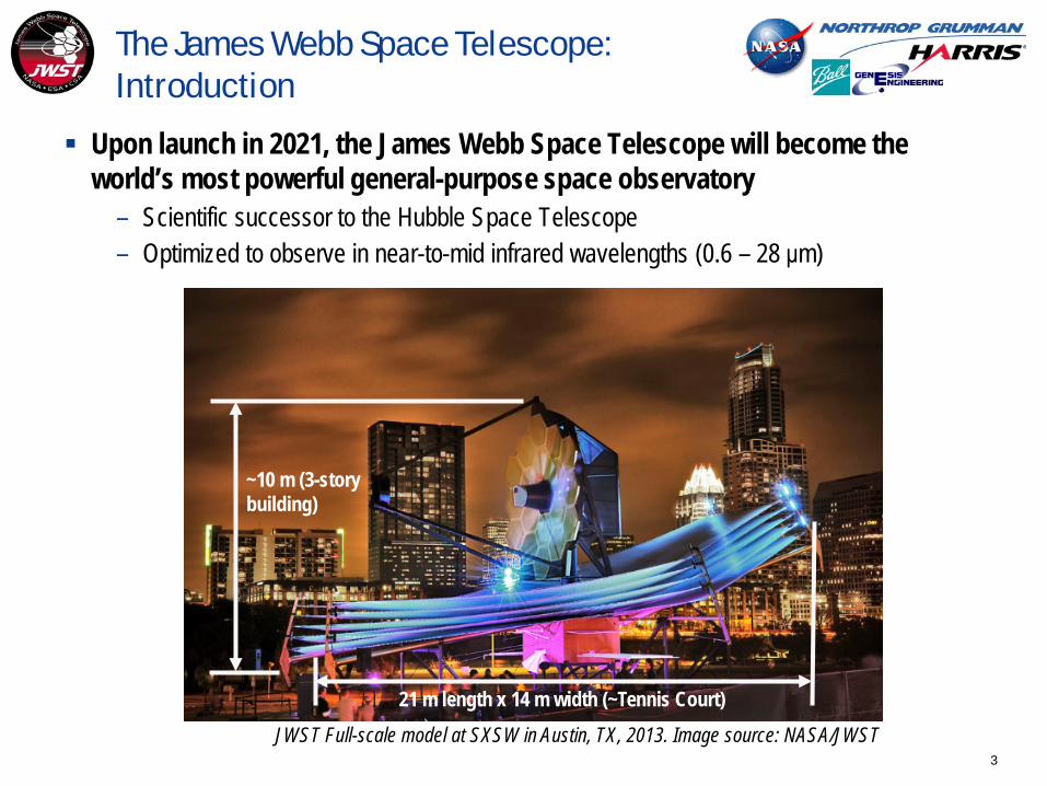
The James Webb Space Telescope: Introduction
Upon launch in 2021, the James Webb Space Telescope will become the world’s most powerful general-purpose space observatory
– Scientific successor to the Hubble Space Telescope– Optimized to observe in near-to-mid infrared wavelengths (0.6 – 28 μm)
21 m length x 14 m width (~Tennis Court)
~10 m (3-story building)
JWST Full-scale model at SXSW in Austin, TX, 2013. Image source: NASA/JWST
4
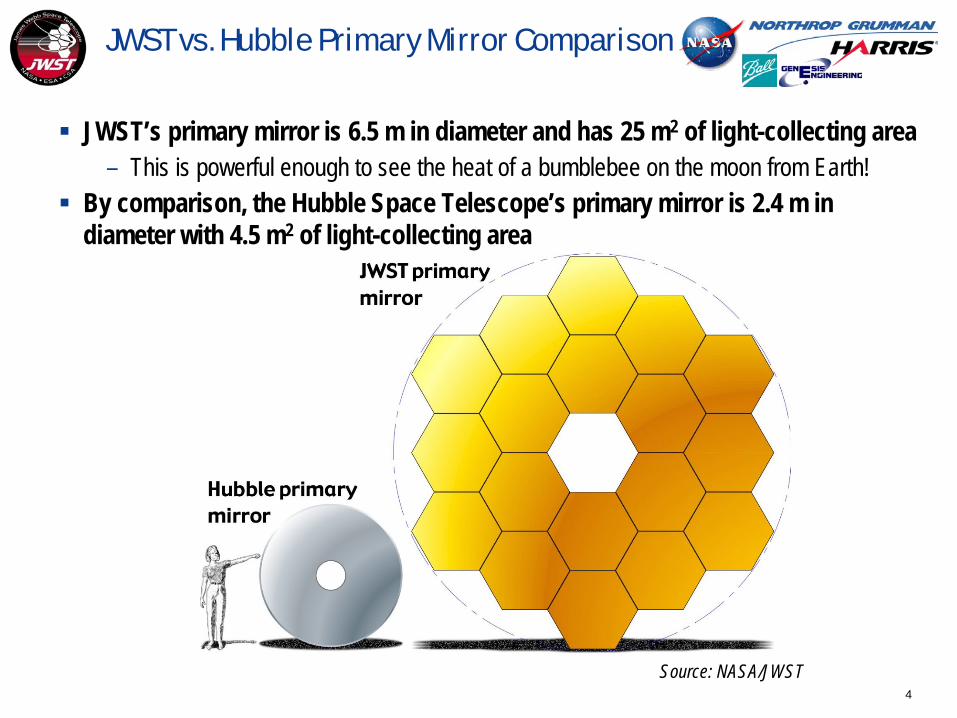
JWST vs. Hubble Primary Mirror Comparison
JWST’s primary mirror is 6.5 m in diameter and has 25 m2 of light-collecting area– This is powerful enough to see the heat of a bumblebee on the moon from Earth!
By comparison, the Hubble Space Telescope’s primary mirror is 2.4 m in diameter with 4.5 m2 of light-collecting area
Source: NASA/JWST

5
JWST Science [3]
First Light and Reionization Planetary Systems and the Origins of Life
Birth of Stars and Protoplanetary Systems
Assembly of Galaxies
Sour
ce: A
LMA
Obse
rvat
ory
Sour
ce: N
ASA/
WM
AP
Sour
ce: N
ASA/
JPL-
Calte
ch
Sour
ce: N
ASA/
ESA
6
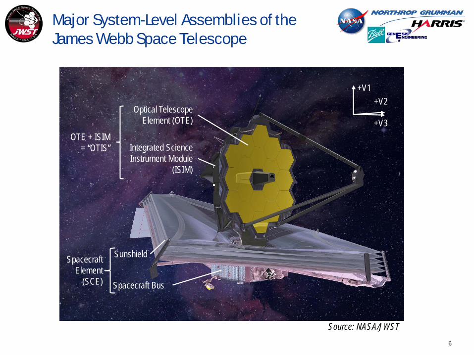
Major System-Level Assemblies of the James Webb Space Telescope
Optical Telescope Element (OTE)
Integrated Science Instrument Module
(ISIM)
Sunshield
OTE + ISIM = “OTIS”
Spacecraft Bus
+V1+V2
+V3
Source: NASA/JWST
Spacecraft Element
(SCE)

7
Completed “OTIS” Element at NASA Goddard Space Flight Center SSDIF Clean Room
Source: NASA/JWST

8
Thermal Environment in Flight
Source: svs.gsfc.nasa.gov
Sun-facing side (hot)Sunshield layer 1: > 350 K
Deep space-facing side (cold)Sunshield layer 5: < 50K
5-layer Sunshield
IEC warm electronics compartment (~278 K)
Near-Infrared instruments (NIRSpec, NIRCam,
FGS/NIRISS): 35-42 K
Mid-Infrared Instrument (MIRI): 6K (actively cooled)
Earth

9
OTIS CV Thermal Test Objectives [4]
Preserve hardware integrity upon transition to cryogenic thermal balance (cryo-balance) conditions and transition back to ambient temperatures by respecting all imposed limits and constraints (L&Cs)
Achieve the simulated on-orbit payload temperature levels and stability for optical, mechanical, and instrument tests
Predict and measure thermal balance test data for model crosscheck, both on ISIM and OTE components
Achieve a workmanship thermal conductance assessment of the flight instrument heat straps which for the first time would be connecting all the payload flight instruments and radiators
Achieve test timeline optimization by executing the OTIS CV cooldown and warmup in a time-efficient manner
10
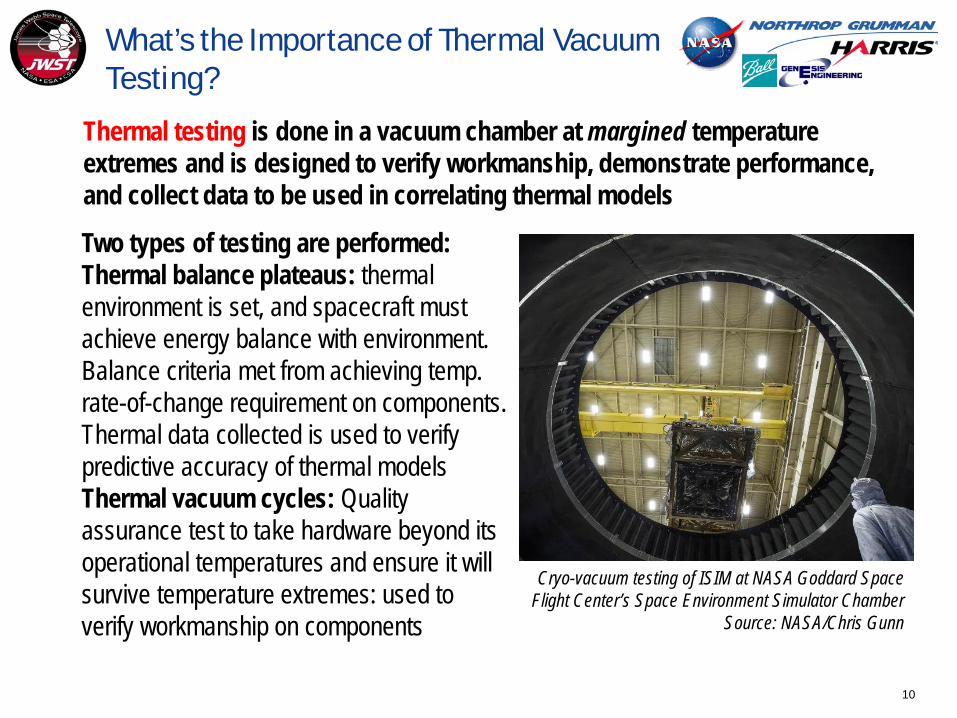
What’s the Importance of Thermal Vacuum Testing?
Thermal testing is done in a vacuum chamber at margined temperature extremes and is designed to verify workmanship, demonstrate performance, and collect data to be used in correlating thermal models
Two types of testing are performed: Thermal balance plateaus: thermal environment is set, and spacecraft must achieve energy balance with environment. Balance criteria met from achieving temp. rate-of-change requirement on components. Thermal data collected is used to verify predictive accuracy of thermal modelsThermal vacuum cycles: Quality assurance test to take hardware beyond its operational temperatures and ensure it will survive temperature extremes: used to verify workmanship on components
Cryo-vacuum testing of ISIM at NASA Goddard Space Flight Center’s Space Environment Simulator Chamber
Source: NASA/Chris Gunn

11
What Are Our Temperature Goals on OTIS?
+V1 Side
-V1 Side
Secondary Mirror19-54 K
Primary Mirrors 32-59 K
Interface with Spacecraft Bus 295 K(Plus surfaces to simulate backloading from the sunshield)
ISIM Electronics Compartment278 K - 288 K
Near-Infrared Instruments and Instrument Radiators
35 K – 42 KMid-Infrared
Instrument 6 K
Imag
e so
urce
s: NA
SA/JW
ST

12
How Do We Replicate JWST’s Flight Thermal Environment in Test ?
Use one of the largest thermal vacuum chambers in the world (NASA Johnson Space Center’s Chamber A)
– Unfortunately, even this chamber is not large enough to fit all of JWST, so we need to test in separate system-level assemblies (OTIS being the major cryogenic test)
Install a gaseous helium shroud to lower the payload temperatures to 20K, and an LN2 shroud to lower the overall environmental loads on the helium shroud/refrigerator [5]
Install GSE to simulate heat from the flight spacecraft bus
Source: NASA/JWST
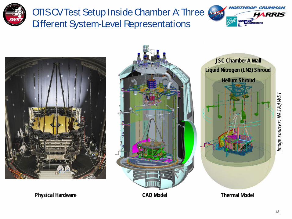
13
OTIS CV Test Setup Inside Chamber A: Three Different System-Level Representations
CAD Model Thermal ModelPhysical Hardware
JSC Chamber A WallLiquid Nitrogen (LN2) Shroud
Helium Shroud
Imag
e so
urce
s: NA
SA/JW
ST
14
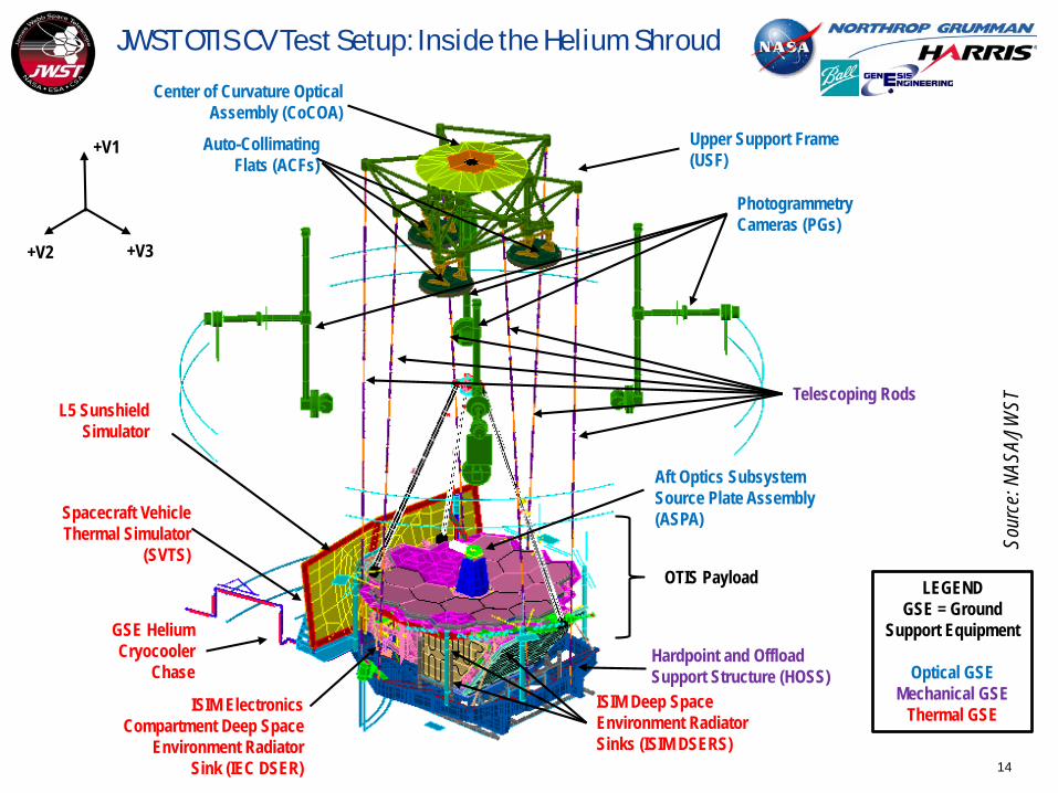
JWST OTIS CV Test Setup: Inside the Helium Shroud
+V3+V2
+V1
Center of Curvature Optical Assembly (CoCOA)
OTIS Payload
Aft Optics Subsystem Source Plate Assembly (ASPA)
GSE Helium Cryocooler
Chase
Spacecraft Vehicle Thermal Simulator
(SVTS)
L5 Sunshield Simulator
Photogrammetry Cameras (PGs)
Upper Support Frame (USF)
Telescoping Rods
Auto-Collimating Flats (ACFs)
Hardpoint and Offload Support Structure (HOSS)
ISIM Deep Space Environment Radiator Sinks (ISIM DSERS)
ISIM Electronics Compartment Deep Space
Environment Radiator Sink (IEC DSER)
LEGENDGSE = Ground
Support Equipment
Optical GSEMechanical GSE
Thermal GSE
Sour
ce: N
ASA/
JWST

15
JWST OTIS CV Test Setup: Payload Configuration
Primary Mirror Segment Assemblies (PMSAs) (18 total)
Primary Mirror Backplane Support Structure (PMBSS) = Backplane (BP) + Backplane Support Fixture (BSF)
Integrated Science Instrument Module (ISIM), which contains the NIRSpec, NIRCam, FGS, and MIRI Instruments
ISIM Electronics Compartment (IEC)(ROOM TEMPERATURE)
Deployable Tower Assembly (DTA)
Secondary Mirror Assembly (SMA)
Aft Optics Subsystem (AOS): Contains Tertiary Mirror (TM) and
Fine Steering Mirror (FSM)
Secondary Mirror Support Structure (SMSS)
+V2
+V3
+V1
Harness Radiator (HR)
Thermal Management System (TMS)
Secondary Mirror (SM) Optical Path
Primary Mirrors
(PMs,18)
TM
FSM
ISIM
Sour
ce: N
ASA/
JWST

16
FSM Baseplate Contamination Control Heater (flight)
SVTS Heater Plates control “Core”
Environment (GSE)
HOSS Cooled through helium line (GSE)
IEC DSER controllable through individual helium zone (GSE)
ISIM DSERS (+V2, -V2, +V3, -V1, HR) in one Helium zone (GSE)
ISIM contains multiple instrument bench and trim heaters (flight): NIRSpec OA, NIRSpecFPA, NIRCam, FGS, MIRI
ISIM Precool Straps controllable through individual helium zone (GSE)
DTA Wagon Wheel Heaters maintain DTA
base at 295K (GSE)
MIRI GSE Cryocooler to provide cold sink
ISIM Precool Strap zero-Q heaters for cryo-balance (GSE)IEC contains suite of
control heaters for the instrument electronics
boxes (flight)
SMA Delta Frame warmup Heater (GSE)
TM Sub-bench Warmup Heater (GSE)
BSF Hardpoint Strut zero-Q heaters control Payload/GSE
interface (GSE)
Red: Heater ControlledBlue: Helium Controlled
OTIS Thermal Control Hardware [6]
For payload: 836 flight sensors, 171 test sensors
(many more test sensors for GSE)
Sour
ce: N
ASA/
JWST

17
GSE Considerations for the Cryogenic Test Environment [7]
A robust thermal instrumentation plan was developed with multiple systems to rigorously interpret cryogenic test results
– Calibrated diodes, precise data acquisition units for accuracy/resolution through range of test temperatures
– Radiometers to measure localized heat sources– Calorimeters for understanding radiative boundaries and icing
Thermal balance test required precise control of boundary heat leaks on the mW scale, and optical / instrument tests required management of stray light entering optical path
– Stationary penetrations on Helium shroud closed out with single layer insulation (SLI) or multi-layer insulation (MLI)
– Specialized systems of light-tight baffles, shell structures, and MLI used for shroud penetrations which moved due to cryo-shift (e.g. Down / Telescoping Rods) or mechanism operations (e.g. photogrammetry cameras)
– Harnessing from external environment was anchored to increasingly colder thermal sinks to reduce stray light into chamber
Screenshot of Harris TTS Data Acquisition System
Source: Harris Corp.
Closeout of Down RodsSource: Harris Corp.

18
How Did We Prepare for OTIS?
Major ISIM Element Thermal Vacuum/Thermal Balance Tests (SES Chamber, NASA GSFC) [8]
Helium Shroud Acceptance Test
Chamber Certification Test
ISIM Structure Cryoset Test
ISIM Structure Cryoproof Test
OSIM Cryo-Cal Test 1
OSIM Cryo-Cal Test 2
ISIM Element Cryo-Vacuum Tests (x3)
OTISMajor OTE Thermal Vacuum/Thermal Balance Tests (Chamber A, NASA JSC) [9-12]
2008 March 2010 May 2010 November 2010 August 2012 May 2013 CV1: Sep-Nov 2013CV2: Jun-Oct 2014
CV3: Nov 2015 - Feb 2016
OTIS Analytical Models: • Contamination• Cryocooler• Mechanical / Dynamics• Optical / Stray Light• Spacecraft Sim / Software• Thermal• Thermal Distortion
Multi-year Development / Iterative Process
Oct 2014 June 2015 Sep-Oct 2015 Sep-Oct 2016
Jul-Oct 2017
Image Sources: NASA/JWST
19
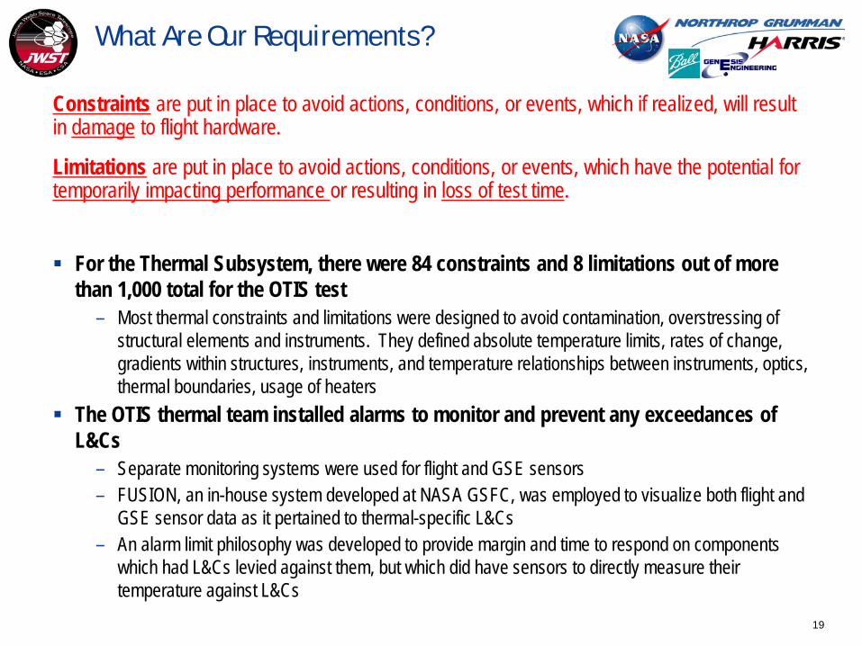
What Are Our Requirements?
Constraints are put in place to avoid actions, conditions, or events, which if realized, will result in damage to flight hardware.
Limitations are put in place to avoid actions, conditions, or events, which have the potential for temporarily impacting performance or resulting in loss of test time.
For the Thermal Subsystem, there were 84 constraints and 8 limitations out of more than 1,000 total for the OTIS test
– Most thermal constraints and limitations were designed to avoid contamination, overstressing of structural elements and instruments. They defined absolute temperature limits, rates of change, gradients within structures, instruments, and temperature relationships between instruments, optics, thermal boundaries, usage of heaters
The OTIS thermal team installed alarms to monitor and prevent any exceedances of L&Cs
– Separate monitoring systems were used for flight and GSE sensors– FUSION, an in-house system developed at NASA GSFC, was employed to visualize both flight and
GSE sensor data as it pertained to thermal-specific L&Cs– An alarm limit philosophy was developed to provide margin and time to respond on components
which had L&Cs levied against them, but which did have sensors to directly measure their temperature against L&Cs

20
Full OTIS Predicted Profile
Cooldown (33 Days) Cryo-Stable (20.9 days)Pre-CryoWarm Vac(6.5 days)
ThermalBalance
(5.2 Days)
Warmup (23 Days) Post-CryoWarm Vac(3.8 days)
Source: NASA/JWST

21
Part I Summary
In this lecture, we reviewed the mission of James Webb Space Telescope’s OTIS element and its thermal architecture
– Science objectives for OTIS– Constituent components (flight and GSE)– Justification for and method of thermal vacuum testing– Thermal test objectives and requirements
In the next lecture, we will focus on the development of the thermal test methodology via thermal analysis
– Assembly of OTIS system-level model– Test profile generation via limit and constraint “feedback loop”– Accommodations for contamination and structural concerns

22
Reference: Acronyms (Page 1)
Acronym Definition Acronym DefinitionAOS Aft Optical System ESA European Space Agency
ACF Auto-Collimating Flat FGS Fine Guidance Sensor
ADIR Aft Deployable ISIM Radiator FIR Fixed ISIM Radiator
ASPA Aft Optical System Source Plate Assembly FPA Focal Plane Arrays
BP Back Plane FSM Fine Steering Mirror
BSF Backplane Support Fixture GSE Ground Support Equipment
CoCOA Center of Curvature Optical Assembly GSFC NASA Goddard Space Flight Center
CPP Cryo-Pumping Panels, cold panels between the Helium and LN2 shrouds at NASA JSC HOSS Hardpoint and Offload Support Structure
CSA Canadian Space Agency IEC ISIM Electronics Compartment
CTE Coefficient of thermal expansion IR Infrared
CV Cryogenic Vacuum ISIM Integrated Science Instrument Module, which contains the Science Instruments (SIs)
ΔT, Δt Change in temperature; change in time JSC NASA Johnson Space Center
DTA Deployable Tower Assembly JWST James Webb Space Telescope
DSERS Deep Space Environment Radiative Sink K Kelvin
EC European Consortium L&Cs Limits and Constraints

23
Reference: Acronyms (Page 2)
Acronym Definition Acronym DefinitionL5 Layer 5 Sunshield simulator POM Instrument Pick-Off MirrorLN2, N2 Liquid Nitrogen; Gaseous Nitrogen PM Primary Mirror(s)LRM Launch Release Mechanism PMSA Primary Mirror Segment Assembly
MIRI Mid-Infrared Instrument PMBSS Primary Mirror Backplane Support Structure (BSF + BP)
MLI Multi-Layer Insulation Q Heat
NASA National Aeronautics and Space Administration SI Science Instrument
NGAS Northrop Grumman Aerospace Systems SINDA Systems Improved Numerical Differential Analyzer modeling tool
NIRCam Near-Infrared Camera Instrument SM Secondary Mirror
NIRSpec Near-Infrared Spectrograph Instrument SMA Secondary Mirror Assembly
OA Optical Assembly SMSS Secondary Mirror Support Structure
OGSE Optical Ground Support Equipment, a series of pre-OTIS Optical pathfinder tests SVTS Space Vehicle thermal Simulator
OTE Optical Telescope Element TM Tertiary Mirror
OTIS Optical Telescope Element plus Integrated ScienceInstrument Module (OTE + ISIM) TPF Thermal Pathfinder test
PG PhotoGrammetry cameras W Watt(s)

24
References (Page 1)
1. Feinberg, L., Voyton, M., Lander, J., Keski-Kuha, R., and Matthews, G. “James Webb Space Telescope Optical Telescope Element/Integrated Science Instrument Module (OTIS) Status.” Proceedings of the SPIE. Volume 9904, id. 990407. 2016.
2. Kimble, R., Apollo, P., Feinberg, L., Glazer, S., Hanley, J., Keski-Kuha, R., Kirk, J., Knight, S., Lambros, S., Lander, J., McGuffey, D., Mehalick, K., Ohl, R., Ousley, W., Reis, C., Reynolds, P., Begoña Vila, M.; Voyton, M., Waldman, M., Whitman, T. “Cryo-Vacuum Testing of JWST’s Integrated Telescope & Scientific Instrument Suite.” American Astronomical Society. AAS Meeting 229, id. 238.14. 2016.
3. Kimble, R. “Cryo-Vacuum Testing the James Webb Space Telescope.” Presented at the NASA Goddard Space Flight Center Engineering Colloquium. March 26, 2018.
4. Yang, K., et al. “Thermal Model Performance for the James Webb Space Telescope OTIS Cryo-Vacuum Test .” 48th International Conference on Environmental Systems. Albuquerque, NM, July 8-12, 2018
5. Homan, J. Cerimele, M., and Montz, M. “Creating the Deep Space Environment for Testing the James Webb Space Telescope at NASA Johnson Space Center's Chamber A.” 43rd International Conference on Environmental Systems. Vail, CO, July 14-18, 2013.
6. Havey, K., Cooke, D., Huguet, J., and Day, R. “Thermal Management of JWST Cryo-Vacuum Test Support Equipment.” 48th International Conference on Environmental Systems. Albuquerque, NM, July 8-12, 2018
7. Huguet, J., Day, R., Havey, K., and Cooke, D. “Thermal Control of Boundaries for JWST Infrared Tests in Cryogenic Vacuum Configuration.” 48th International Conference on Environmental Systems. Albuquerque, NM, July 8-12, 2018
25
References (Page 2)
8. Glazer, S., and Comber, B. “James Webb Space Telescope Integrated Science Instrument Module Thermal Vacuum/Thermal Balance Test Campaign at NASA's Goddard Space Flight Center.” 46th
International Conference on Environmental Systems. Vienna, Austria, July 13-17, 20169. Park, S., Brinckerhoff, P., Franck, R., Schweickart, R., Thomson, S., Burt, W., and Ousley, W.
“Successful Completion of the JWST OGSE2 Cryogenic Test at JSC Chamber-A while Managing Numerous Challenges.” 46th International Conference on Environmental Systems. Vienna, Austria, July 13-17, 2016.
10. Ousley, W., Burt, W., and Davis, A. “James Webb Space Telescope Cryogenic Thermal Pathfinder Test” 44th International Conference on Environmental Systems. Tucson, AZ, July 13-17, 2014.
11. Davis, A., Ousley, W., Burt, W., and Cottingham, C. “James Webb Space Telescope Thermal Pathfinder Test Development.” 46th International Conference on Environmental Systems. Vienna, Austria, July 13-17, 2016.
12. Davis, A., Ousley, W., and Burt, W. “James Webb Space Telescope Thermal Pathfinder Test Results.” 47th International Conference on Environmental Systems. Charleston, SC, July 17-20, 2017.