jackie cvt review asme-wc draft dj v2 - engr.uvic.camech459/pub_references/jackie cvt review...
TRANSCRIPT
1 Copyright © 2011 by ASME
Proceedings of the ASME 2011 International Mechanical Engineering Congress & Exposition IMECE2011
November 11-17, 2011, Denver, Colorado, USA
IMECE2011-63321
REVIEW OF CONTINUOUSLY VARIABLE TRANSMISSION POWERTRAIN SYSTEM FOR HYBRID ELECTRIC VEHICLES
Jian Dong University of Victoria Victoria, BC, Canada
Zuomin Dong University of Victoria Victoria, BC, Canada
Curran Crawford University of Victoria Victoria, BC, Canada
ABSTRACT
In this paper, a review of the state-of-the-art of various CVT powertrain systems now used or being planned for future use in HEVs is presented. These CVT powertrain systems are classified into three main categories: mechanical CVT, electromechanical CVT(ECVT) and pure electrical CVT(EVT). The research development, system architecture, operation characteristics and the merits and drawbacks of each type are discussed.
INTRODUCTION Continuously Variable Transmission(CVT) are being developed in conjunction with Hybrid Electric Vehicles(HEV), which have provided great potential for better fuel economy and lower emissions. The use of CVT is optimal for HEV: the electric portion of the HEV powertrain system avoids the low-speed/high-torque problems of CVTs, while still attaining better fuel economy than other transmissions at high speeds by enabling the engine to run at its most efficient regime. Moreover, the integration of electric machine enables the function of CVT, starter and generator, and is especially suitable for HEVs.
In this paper, a review of the state-of-the-art of various CVT powertrain systems now used or being planned for future use in HEVs is presented. These CVT powertrain systems are classified into three main categories: mechanical CVT, electromechanical CVT(ECVT) and pure electrical CVT(EVT). The research development, system configuration, operation characteristics and the merits and drawbacks of each type are discussed.
The mechanical type CVT powertrain system used in HEV in this paper includes metal belt CVT, which are usually used in parallel with an electric motor. By connecting to a Planetary Gear Set(PGS), the belt CVT can be converted into an Infinitely Variable Transmissions(IVT) capable of providing a
full range of ratio from reverse, through stationary to forward. The mechanical type CVT powertain systems without PGS and with PGS(hence IVT) used in HEV are explored respectively.
The electromechanical type CVT, or power-split electronic-CVT(ECVT) powertrain system consists of an electric variator and several PGSs. According to the power flow type, three categories of ECVT powertrain systems are discussed and compared: the input-split ECVT, the output-split ECVT and the compound-split ECVT. The one-mode input-split and output-split ECVT contains one PGS and two motors, while the multi-mode compound-split ECVT contains at least two PGSs. The connection topology, torque and speed relationship of each mode of the three ECVT powertrain systems is analyzed and the performances of the three systems are compared.
The pure electrical type CVT, or EVT powertrain system is a class of recently developed propulsion systems, which basically comprise concentrically arranged double-rotor or double-stator electric machines to perform power split. They contain no mechanical PGS and therefore reduce mechanical friction, avoid audible noise and achieve system simplicity. Discussion focuses on the system configuration, power flow and torque relationship and operational features.
MECHANICAL TYPE CVT POWERTRAIN SYSTEM IN HEV
The mechanical type CVT powertrain system used in HEV in this paper includes metal belt CVT, which are usually used in parallel with an electric machine.
The commercially available belt type CVT has evaluated to a electronic controllable transmission system since 1980s, based on a metal belt, which has highest efficiency among other belt type CVTs or traction based CVTs. Mechanical metal belt type CVT can provide smooth, seamless shifts and improved fuel
2 Copyright © 2011 by ASME
efficiency. They are currently produced by Jatco, Aisin, ZF, Toyota, Subaru, Daimler Chrysler, Audi, etc[1].
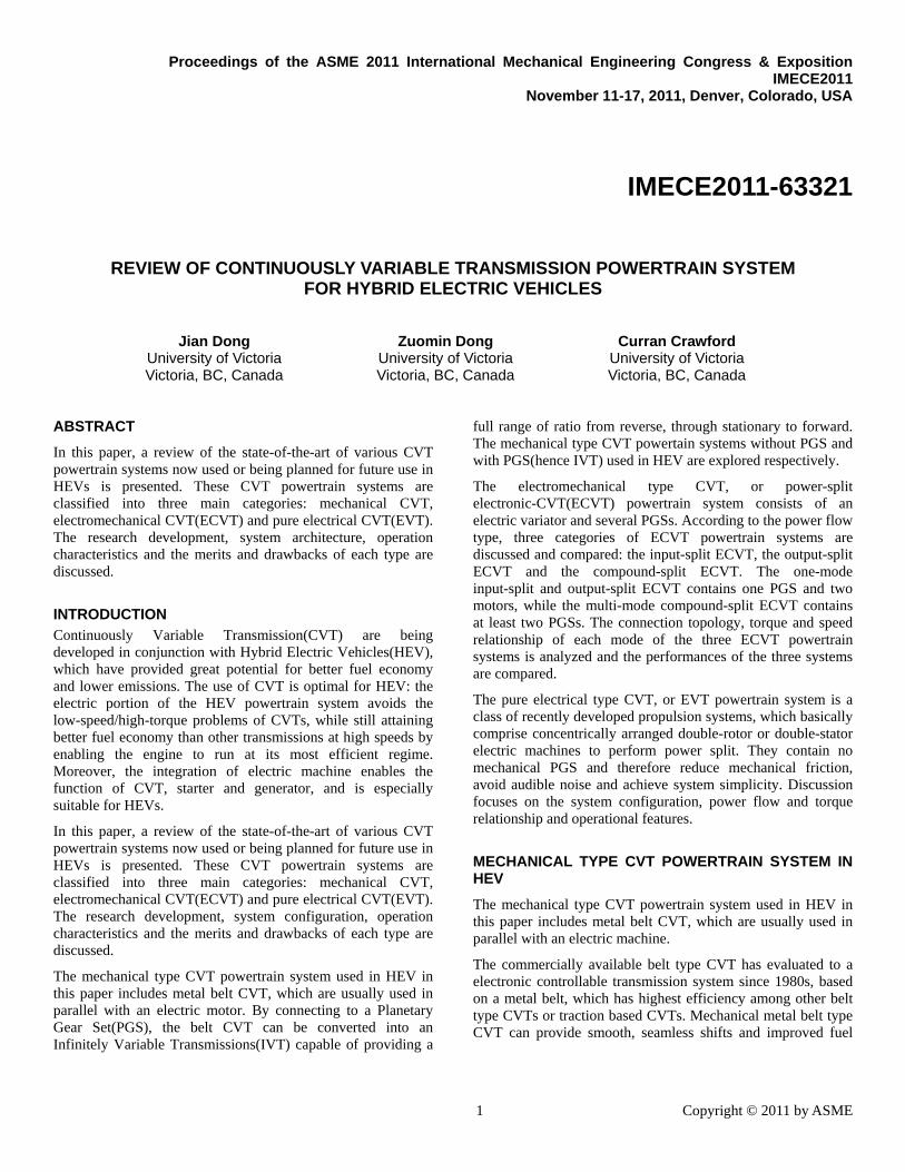
For HEV powertrain systems, the low-cost mechanical metal belt CVT is combined to an electric machine in an parallel way. The electric machine(motor/generator) is usually coupled between the clutch and the CVT at the engine side. This allows the engine to be turned off during the propulsion phases since the vehicle can be propelled only by the electric machine. An additional starter-alternator is needed for engine restart during standstill. Figure 1 shows the configuration of such a powertrain system.
Fig 1. Belt CVT hybrid electric powertrain system
Honda IMA Belt CVT Hybrid Powertrain
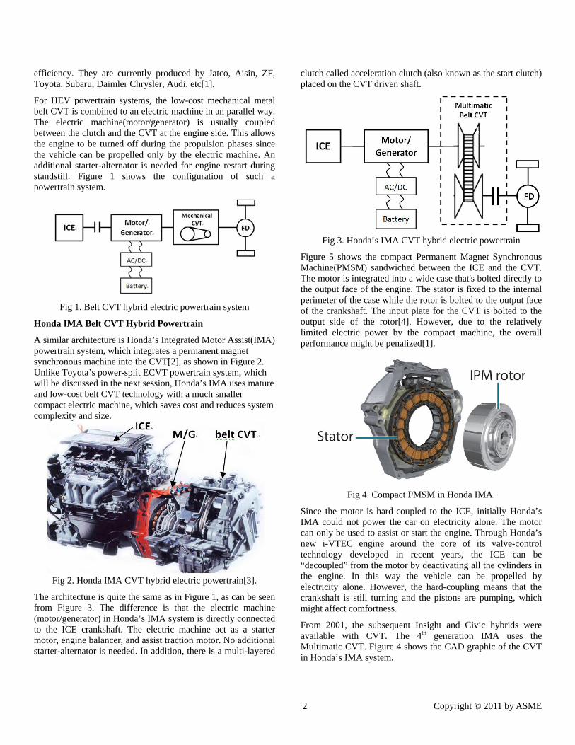
A similar architecture is Honda’s Integrated Motor Assist(IMA) powertrain system, which integrates a permanent magnet synchronous machine into the CVT[2], as shown in Figure 2. Unlike Toyota’s power-split ECVT powertrain system, which will be discussed in the next session, Honda’s IMA uses mature and low-cost belt CVT technology with a much smaller compact electric machine, which saves cost and reduces system complexity and size.
Fig 2. Honda IMA CVT hybrid electric powertrain[3].
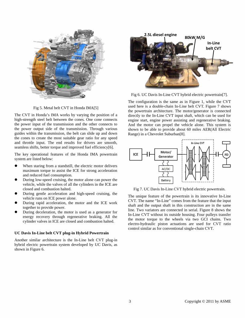
The architecture is quite the same as in Figure 1, as can be seen from Figure 3. The difference is that the electric machine (motor/generator) in Honda’s IMA system is directly connected to the ICE crankshaft. The electric machine act as a starter motor, engine balancer, and assist traction motor. No additional starter-alternator is needed. In addition, there is a multi-layered
clutch called acceleration clutch (also known as the start clutch) placed on the CVT driven shaft.
Fig 3. Honda’s IMA CVT hybrid electric powertrain
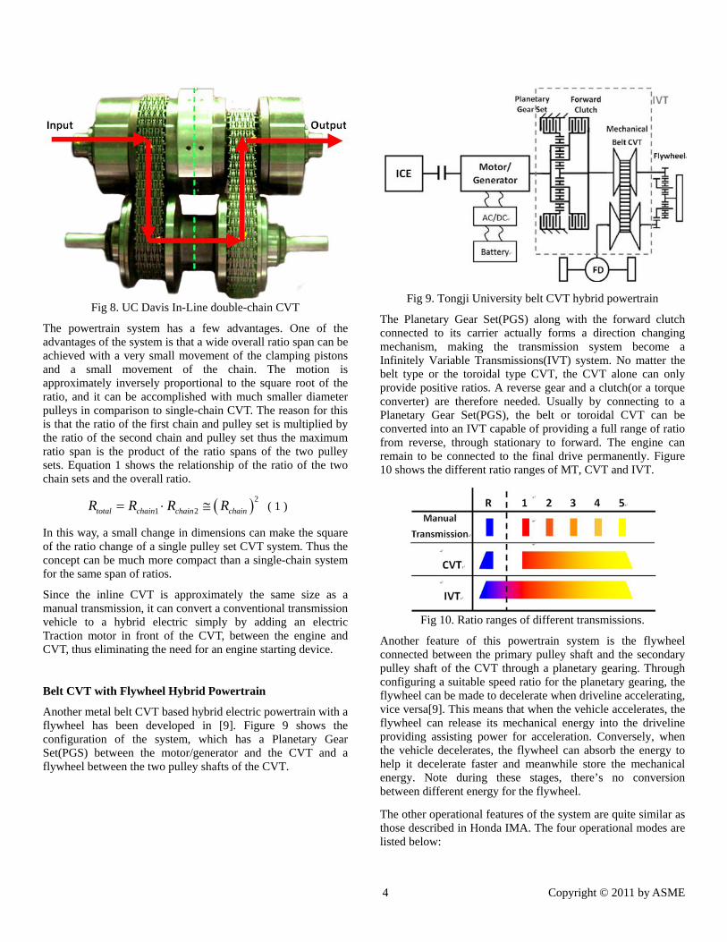
Figure 5 shows the compact Permanent Magnet Synchronous Machine(PMSM) sandwiched between the ICE and the CVT. The motor is integrated into a wide case that's bolted directly to the output face of the engine. The stator is fixed to the internal perimeter of the case while the rotor is bolted to the output face of the crankshaft. The input plate for the CVT is bolted to the output side of the rotor[4]. However, due to the relatively limited electric power by the compact machine, the overall performance might be penalized[1].
Fig 4. Compact PMSM in Honda IMA.
Since the motor is hard-coupled to the ICE, initially Honda’s IMA could not power the car on electricity alone. The motor can only be used to assist or start the engine. Through Honda’s new i-VTEC engine around the core of its valve-control technology developed in recent years, the ICE can be “decoupled” from the motor by deactivating all the cylinders in the engine. In this way the vehicle can be propelled by electricity alone. However, the hard-coupling means that the crankshaft is still turning and the pistons are pumping, which might affect comfortness.
From 2001, the subsequent Insight and Civic hybrids were available with CVT. The 4th generation IMA uses the Multimatic CVT. Figure 4 shows the CAD graphic of the CVT in Honda’s IMA system.
3 Copyright © 2011 by ASME
Fig 5. Metal belt CVT in Honda IMA[5]
The CVT in Honda’s IMA works by varying the position of a high-strength steel belt between the cones. One cone connects the power input of the transmission and the other connects to the power output side of the transmission. Through various guides within the transmission, the belt can slide up and down the cones to create the most suitable gear ratio for any speed and throttle input. The end results for drivers are smooth, seamless shifts, better torque and improved fuel efficiency[6].
The key operational features of the Honda IMA powertrain system are listed below:
When staring from a standstill, the electric motor delivers maximum torque to assist the ICE for strong acceleration and reduced fuel consumption.
During low-speed cruising, the motor alone can power the vehicle, while the valves of all the cylinders in the ICE are closed and combustion halted.
During gentle acceleration and high-speed cruising, the vehicle runs on ICE power alone.
During rapid acceleration, the motor and the ICE work together to provide power.
During deceleration, the motor is used as a generator for energy recovery through regenerative braking. All the cylinder valves in ICE are closed and combustion halted.
UC Davis In-Line belt CVT plug-in Hybrid Powertrain
Another similar architecture is the In-Line belt CVT plug-in hybrid electric powertrain system developed by UC Davis, as shown in Figure 6.
Fig 6. UC Davis In-Line CVT hybrid electric powertrain[7].
The configuration is the same as in Figure 1, while the CVT used here is a double-chain In-Line belt CVT. Figure 7 shows the powertrain architecture. The motor/generator is connected directly to the In-Line CVT input shaft, which can be used for engine start, engine power assisting and regenerative braking. And the motor can propel the vehicle alone. This system is shown to be able to provide about 60 miles AER(All Electric Range) in a Chevrolet Suburban[8].
Fig 7. UC Davis In-Line CVT hybrid electric powertrain.
The unique feature of the powertrain is its innovative In-Line CVT. The name “In-Line” comes from the feature that the input shaft and the output shaft in this construction are in the same line. Two variators are connected in serial. Figure 8 shows the In-Line CVT without its outside housing. Four pulleys transfer the motor torque to the wheels via two GCI chains. Two electro-hydraulic piston actuations are used for CVT ratio control similar as for conventional single-chain CVT.
2.5L diesel engine 80kW M/G
In‐Line belt CVT
4 Copyright © 2011 by ASME
Fig 8. UC Davis In-Line double-chain CVT
The powertrain system has a few advantages. One of the advantages of the system is that a wide overall ratio span can be achieved with a very small movement of the clamping pistons and a small movement of the chain. The motion is approximately inversely proportional to the square root of the ratio, and it can be accomplished with much smaller diameter pulleys in comparison to single-chain CVT. The reason for this is that the ratio of the first chain and pulley set is multiplied by the ratio of the second chain and pulley set thus the maximum ratio span is the product of the ratio spans of the two pulley sets. Equation 1 shows the relationship of the ratio of the two chain sets and the overall ratio.
2
1 2total chain chain chainR R R R ( 1 )
In this way, a small change in dimensions can make the square of the ratio change of a single pulley set CVT system. Thus the concept can be much more compact than a single-chain system for the same span of ratios.
Since the inline CVT is approximately the same size as a manual transmission, it can convert a conventional transmission vehicle to a hybrid electric simply by adding an electric Traction motor in front of the CVT, between the engine and CVT, thus eliminating the need for an engine starting device.
Belt CVT with Flywheel Hybrid Powertrain
Another metal belt CVT based hybrid electric powertrain with a flywheel has been developed in [9]. Figure 9 shows the configuration of the system, which has a Planetary Gear Set(PGS) between the motor/generator and the CVT and a flywheel between the two pulley shafts of the CVT.
Fig 9. Tongji University belt CVT hybrid powertrain
The Planetary Gear Set(PGS) along with the forward clutch connected to its carrier actually forms a direction changing mechanism, making the transmission system become a Infinitely Variable Transmissions(IVT) system. No matter the belt type or the toroidal type CVT, the CVT alone can only provide positive ratios. A reverse gear and a clutch(or a torque converter) are therefore needed. Usually by connecting to a Planetary Gear Set(PGS), the belt or toroidal CVT can be converted into an IVT capable of providing a full range of ratio from reverse, through stationary to forward. The engine can remain to be connected to the final drive permanently. Figure 10 shows the different ratio ranges of MT, CVT and IVT.
Fig 10. Ratio ranges of different transmissions.
Another feature of this powertrain system is the flywheel connected between the primary pulley shaft and the secondary pulley shaft of the CVT through a planetary gearing. Through configuring a suitable speed ratio for the planetary gearing, the flywheel can be made to decelerate when driveline accelerating, vice versa[9]. This means that when the vehicle accelerates, the flywheel can release its mechanical energy into the driveline providing assisting power for acceleration. Conversely, when the vehicle decelerates, the flywheel can absorb the energy to help it decelerate faster and meanwhile store the mechanical energy. Note during these stages, there’s no conversion between different energy for the flywheel.
The other operational features of the system are quite similar as those described in Honda IMA. The four operational modes are listed below:
5 Copyright © 2011 by ASME
Motor mode: during start-up and for low-speed cruising, the motor drives the vehicle alone.
Power mode: the motor and the ICE power the vehicle together for strong acceleration.
Engine/Charging mode: during deceleration, the motor acts as a generator for energy recovery through regenerative braking. The clutch between the ICE and the motor cuts off the power from ICE.
Engine mode: the ICE drives the vehicle alone.
The merit of this CVT flywheel hybrid electric powertrain is that it combines the battery-electric and flywheel energy storage together for the hybrid electric vehicles. Batteries are great for long-time energy storage, while flywheels are good for transient energy storage. On the one hand, during fierce acceleration/deceleration and the subsequent quick charge/discarge, the battery life can severely be shorten, while flywheel energy storage system proves more efficient during these sharp swings of acceleration/deceleration states since it has no energy conversion. On the other hand, flywheel systems have energy losses mainly due to bearing friction, which makes them less efficient than a battery-based system for storing energy for long periods of time. The combination is probably the ideal solution for hybrid electric vehicles.
ELECTROMECHANICAL TYPE CVT POWERTRAIN SYSTEM IN HEV
The power-split CVT based hybrid electric powertrain have been developed and used for decades in the market, since Toyota first introduced its Prius to the world in 1997.
The electromechanical type CVT, or power-split electric/electronic CVT(ECVT) powertrain system consists of several electric machines and mechanical Planetary Gear Sets(PGS). The engine input power is usually split into two flows and passes through both an electric path(or electric variator) and a mechanical path to the transmission output. The power-split system combines the advantages of both the series and parallel hybrid powertrain.
The merits of such a powertrain system are listed below:
The CVT nature of the system enables the engine to always operate at its most energy-efficient operating point, hence resulting in a considerable reduction of the fuel consumption.
The ECVT powertrain systems are actually IVT systems, which can provide infinite variable ratio between the engine speed and the wheel speed. The absence of additional clutches, torque converters or shifting gears can significantly improve the transmission efficiency and reduce the overall size.
The engine can be completely shut down when the vehicle is stopped, enabling the “idle stop” function.
The ECVT powertrain system usually uses several electric Motor/Generator(MG1 and MG2) connected to the PGS. The motor can be used to start the engine, launch the vehicle,
assist the engine power, provide regenerative braking or power the vehicle alone with electricity.
Most conventional CVT designs are friction-based belt and traction types that are unsuitable for high-torque and high-power applications[10]. The limitation for torque transfer capability can be improved in power-split CVT, as the power flow through the electric variator decreased.
According to the power flow type, three categories of ECVT powertrain systems are discussed and compared: the input-split ECVT, the output-split ECVT and the compound-split ECVT. The input-split and output-split ECVT systems are also called one-mode systems, while the compound-split ECVT systems are called multi-mode systems. The one-mode input-split and output-split ECVT contains one PGS and two motors, while the multi-mode compound-split ECVT contains at least two PGSs. The connection topology, static and dynamic characteristics of each mode of the three ECVT powertrain systems is analyzed and the performances of the three systems are compared.
1. Input-split ECVT Powertrain System
The input-split ECVT powertrain system consists of one Planetary Gear Set (PGS) and two electric Motor/Generator(MG1 and MG2). The Planetary Gear Set(PGS) functions as a power split device, which is placed at the input of the transmission system.
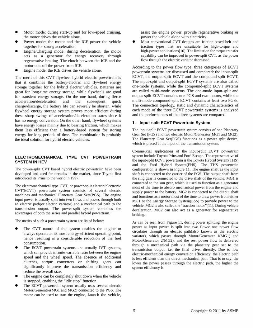
Commercial applications of the input-split ECVT powertrain system include Toyota Prius and Ford Escape. The representative of the input-split ECVT powertrain is the Toyota Hybrid System(THS) and the Ford Hybrid System(FHS). The THS powertrain configuration is shown in Figure 11. The engine shaft as the input shaft is connected to the carrier of the PGS. The output shaft from the ring gear is connected to the drive shaft of the vehicle. MG1 is connected to the sun gear, which is used to function as a generator most of the time to absorb mechanical power from the engine and supply power to the battery. MG2 is connected to the output shaft and functions as a motor most of the time to draw power from either MG1 or the Energy Storage System(ESS) to provide power to the vehicle. MG2 is also called the “traction motor”[11]. During vehicle deceleration, MG2 can also act as a generator for regenerative braking.
As can be seen from Figure 11, during power splitting, the engine power as input power is split into two flows: one power flow circulates through an electric path(also known as the electric variator), which passes through Motor/Generater 1(MG1) and Motor/Generator 2(MG2), and the rest power flow is delivered through a mechanical path via the planetary gear set to the transmission output, i.e. the final drive, directly. Due to low electric-mechanical energy conversion efficiency, the electric path is less efficient than the direct mechanical path. That is to say, the lower the power passes through the electric path, the higher the system efficiency is.
6 Copyright © 2011 by ASME
Fig 11. Power split in THS input-split ECVT powertrain system
One of the important characteristics of the power-split architectures is that at certain operating points the power through the electric path becomes zero, which means all the power is delivered through the mechanical path and therefore maximum system efficiency occurs at these points, since no transmitted power is converted into electricity and back again. Such an operating point is known as a “node point” or “mechanical point”[12]. And the input-to-output speed ratio where the mechanical node point occurs is typically chosen to be in the frequently used area when designing the one-mode hybrid for good fuel economy.
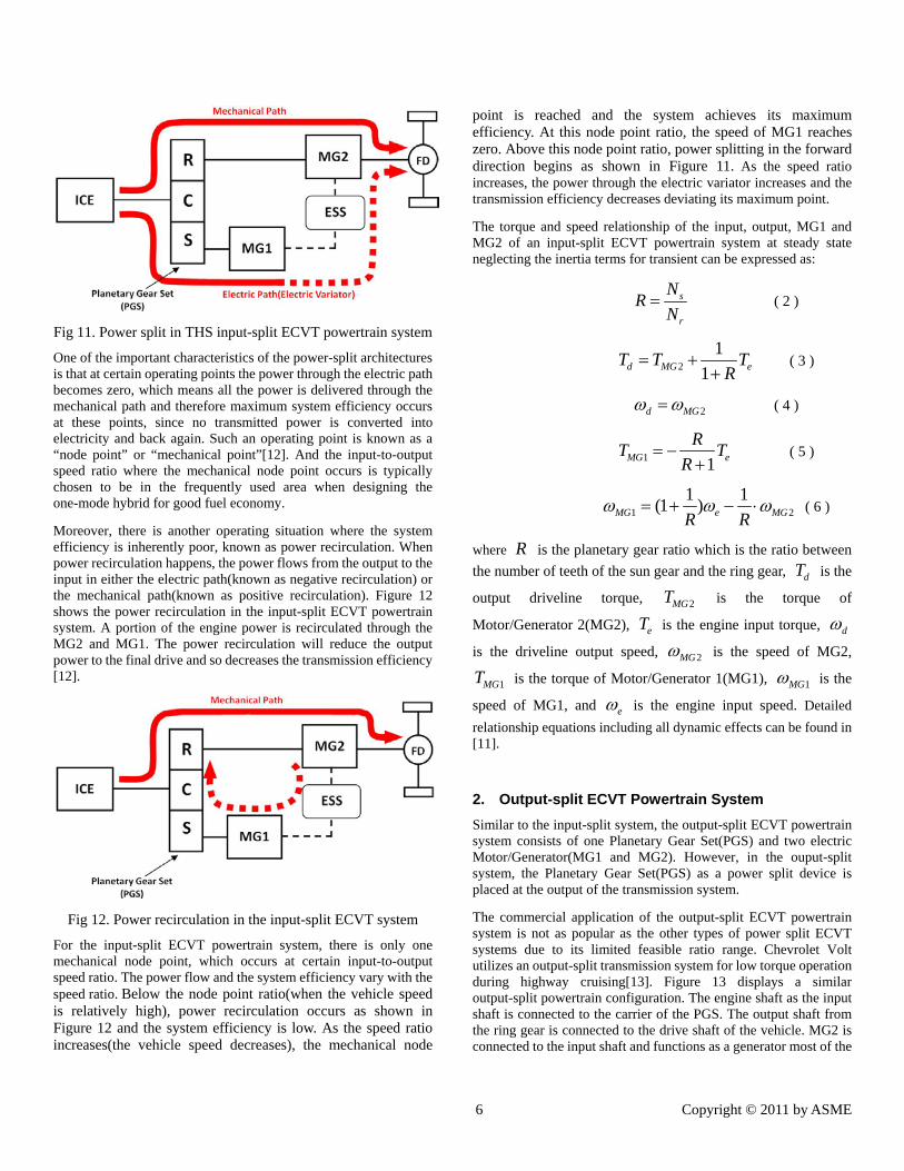
Moreover, there is another operating situation where the system efficiency is inherently poor, known as power recirculation. When power recirculation happens, the power flows from the output to the input in either the electric path(known as negative recirculation) or the mechanical path(known as positive recirculation). Figure 12 shows the power recirculation in the input-split ECVT powertrain system. A portion of the engine power is recirculated through the MG2 and MG1. The power recirculation will reduce the output power to the final drive and so decreases the transmission efficiency [12].
Fig 12. Power recirculation in the input-split ECVT system
For the input-split ECVT powertrain system, there is only one mechanical node point, which occurs at certain input-to-output speed ratio. The power flow and the system efficiency vary with the speed ratio. Below the node point ratio(when the vehicle speed is relatively high), power recirculation occurs as shown in Figure 12 and the system efficiency is low. As the speed ratio increases(the vehicle speed decreases), the mechanical node
point is reached and the system achieves its maximum efficiency. At this node point ratio, the speed of MG1 reaches zero. Above this node point ratio, power splitting in the forward direction begins as shown in Figure 11. As the speed ratio increases, the power through the electric variator increases and the transmission efficiency decreases deviating its maximum point.
The torque and speed relationship of the input, output, MG1 and MG2 of an input-split ECVT powertrain system at steady state neglecting the inertia terms for transient can be expressed as:
s
r
NR
N ( 2 )
2
1
1d MG eT T TR
( 3 )
2d MG ( 4 )
1 1MG e
RT T
R
( 5 )
1 2
1 1(1 )MG e MGR R
( 6 )
where R is the planetary gear ratio which is the ratio between
the number of teeth of the sun gear and the ring gear, dT is the
output driveline torque, 2MGT is the torque of
Motor/Generator 2(MG2), eT is the engine input torque, d
is the driveline output speed, 2MG is the speed of MG2,
1MGT is the torque of Motor/Generator 1(MG1), 1MG is the
speed of MG1, and e is the engine input speed. Detailed
relationship equations including all dynamic effects can be found in [11].
2. Output-split ECVT Powertrain System
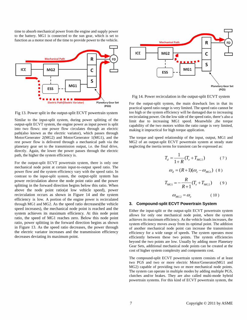
Similar to the input-split system, the output-split ECVT powertrain system consists of one Planetary Gear Set(PGS) and two electric Motor/Generator(MG1 and MG2). However, in the ouput-split system, the Planetary Gear Set(PGS) as a power split device is placed at the output of the transmission system.
The commercial application of the output-split ECVT powertrain system is not as popular as the other types of power split ECVT systems due to its limited feasible ratio range. Chevrolet Volt utilizes an output-split transmission system for low torque operation during highway cruising[13]. Figure 13 displays a similar output-split powertrain configuration. The engine shaft as the input shaft is connected to the carrier of the PGS. The output shaft from the ring gear is connected to the drive shaft of the vehicle. MG2 is connected to the input shaft and functions as a generator most of the
7 Copyright © 2011 by ASME
time to absorb mechanical power from the engine and supply power to the battery. MG1 is connected to the sun gear, which is set to function as a motor most of the time to provide power to the vehicle.
Fig 13. Power split in the output-split ECVT powertrain system
Similar to the input-split system, during power splitting of the output-split ECVT system, the engine power as input power is split into two flows: one power flow circulates through an electric path(also known as the electric variator), which passes through Motor/Generater 2(MG2) and Motor/Generator 1(MG1), and the rest power flow is delivered through a mechanical path via the planetary gear set to the transmission output, i.e. the final drive, directly. Again, the lower the power passes through the electric path, the higher the system efficiency is.
For the output-split ECVT powertrain system, there is only one mechanical node point at certain input-to-output speed ratio. The power flow and the system efficiency vary with the speed ratio. In contrast to the input-split system, the output-split system has power recirculation above the node point ratio and the power splitting in the forward direction begins below this ratio. When above the node point ratio(at low vehicle speed), power recirculation occurs as shown in Figure 14 and the system efficiency is low. A portion of the engine power is recirculated through MG1 and MG2. As the speed ratio decreases(the vehicle speed increases), the mechanical node point is reached and the system achieves its maximum efficiency. At this node point ratio, the speed of MG1 reaches zero. Below this node point ratio, power splitting in the forward direction begins as shown in Figure 13. As the speed ratio decreases, the power through the electric variator increases and the transmission efficiency decreases deviating its maximum point.
Fig 14. Power recirculation in the output-split ECVT system
For the output-split system, the main drawback lies in that its practical speed ratio range is very limited. The speed ratio cannot be too high or the system efficiency will be damaged due to increasing recirculating power. On the low side of the speed ratio, there’s also a limit due to increasing MG1 speed. Meanwhile ,the torque capability of the two motors within the ratio range is very limited, making it impractical for high torque application.
The torque and speed relationship of the input, output, MG1 and MG2 of an output-split ECVT powertrain system at steady state neglecting the inertia terms for transient can be expressed as:
2
1( )
1d e MGT T TR
( 7 )
1( 1)( )d e MGR ( 8 )
1 2( )1MG e MG
RT T T
R
( 9 )
2MG e ( 10 )
3. Compound-split ECVT Powertrain System
Either the input-split or the output-split ECVT powertrain system allows for only one mechanical node point, where the system achieves its maximum efficiency. As the vehicle loads increases, the system efficiency moves away from its optimal point. The addition of another mechanical node point can increase the transmission efficiency for a wide range of speeds. The system operates most efficiently between these two points. The system efficiencies beyond the two points are low. Usually by adding more Planetary Gear Sets, additional mechanical node points can be created at the cost of higher system complexity and components cost.
The compound-split ECVT powertrain system consists of at least two PGS and two or more electric Motor/Generator(MG1 and MG2) capable of providing two or more mechanical node points. The system can operate in multiple modes by adding multiple PGS, clutches and/or brakes. They are also called multi-mode hybrid powertrain systems. For this kind of ECVT powertrain system, the

8 Copyright © 2011 by ASME
power split devices are placed at both the input and the output of the transmission system.
Commercial applications of the multi-mode ECVT hybrid powertrain system include Allison EV Drive, GM Tahoe, Chrysler Aspen, BMW X6, Mercedes ML450 and etc. The representatives of the compound-split (or multi-mode) ECVT powertrain system are the two-mode Allison Hybrid System(AHS). The two-mode ECVT was developed and produced by General Motors for transit buses and full-size SUVs from 2003. Figure 15 shows the schematic cross section of the two-mode hybrid system with fixed gear ratios(also known as the Allison Hybrid system-2(AHS2)) developed by GM. The design is developed to provide higher towing capacity and better acceleration performance for full-size SUVs including the GMC Yukon and Chevrolet Tahoe[15]. The system can operate in two ECVT modes(the input-split low range mode and the compound-split high range mode) and four fixed gear ratio modes through proper selection of the clutch application [16].
Fig 15. Two-mode hybrid system with fixed gear ratios(GM Allison Hybrid System-2)[15].
As shown in Figure 15, the transmission system contains two 60kW permanent magnet motors(MG1 and MG2) and three Planetary Gear Sets(PGS) with four clutches. The engine is connected to the ring gear of the first PGS. The carriers of the first and the second PGS are connected to the main transmission shaft. The ring gear of the second PGS is connected to the sun gear of the first PGS and MG1. The sun gear of the second PGS is connected to the sun gear of the third PGS and MG2. The output driveshaft to the wheel is connected via clutch C2 to the carrier of the third PGS. The ring gear of the third PGS is connected via clutch C1 to a fixed member. In addition, clutch C3 and C4 are added in the design for providing the four fixed gear ratios that allow the transmission to run in parallel mode.
In the input-split low range mode, clutch C1 is engaged and the other three clutches are disengaged. The system configuration in low range mode is shown in Figure 16. Comparing with the input-split system shown in Figure 11, the two-mode AHS-2 in its low range mode provides the same input-split regime. The third PGS acts as a torque multiplier. During power splitting, MG1 operates as a generator to absorb a potion of the mechanical power from the engine and provide power to the ESS, while MG2 operates as a motor to provide power to the output driveshaft via torque multiplier PGS3. There is one mechanical node point in the input-split low range mode, where the speed of MG1 reaches zero. The node point in low range mode is designed to be at a high
numerical transmission ratio corresponding to a relatively low vehicle speed, so that a lower amount of motor power is required to meet the output power demand as it did in a comparable one-mode input-split system[15].
Fig 16. The two-mode AHS-2: input-split low range mode
In the input-split low range mode, the torque and speed relationship of the input, output, MG1 and MG2 of the two-mode ECVT powertrain system can be expressed as:
1
1
r
s
Na
N , 1 1
1
s r
s
N Nb
N
, 2
1 2
r
s r
Nc
N N
,
2
1 2
s
s r
Nd
N N
, 3 3
3
s r
s
N Ne
N
, 3
3
r
s
Nf
N ( 11 )
1 21d MG MG
bdeT T e T
bc
( 12 )
2
1d MGe
( 13 )
1
1( )MG e e e
bcT T J
a
( 14 )
1 1 1MG d e
bde a
bc bc
( 15 )
where 1rN is the number of the ring gear teeth of PGS1, 1sN
is the number of the sun gear teeth of PGS1, 2rN is the
number of the ring gear teeth of PGS2, 2sN is the number of
the sun gear teeth of PGS2, 3rN is the number of the ring
gear teeth of PGS3, 3sN is the number of the sun gear teeth
of PGS3.
When clutch C1 is disengaged and C2 is engaged, the system is shifted to its compound-split high range mode including both input and output split. Figure 17 shows the system configuration in high range mode. The connection of the carriers and the sun gears of the second and the third PGS actually make PGS2 and PGS3 work synchronously. The two PGS together form a power splitting device at the output of the transmission.
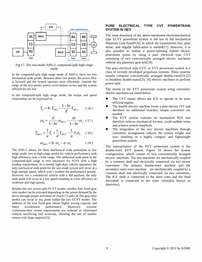
9 Copyright © 2011 by ASME
Fig 17. The two-mode AHS-2: compound-split high range mode
In the compound-split high range mode of AHS-2, there are two mechanical node points. Between these two points, the power flow is forward and the system operates most efficiently. Outside the range of the two points, power recirculation occurs and the system efficiencies are low.
In the compound-split high range mode, the torque and speed relationship can be expressed as:
1 2
1d MG MG
bcT b T T
d
( 16 )
21 1d MG e
d ac
bc bc
( 17 )
1 2
1 1MG e MG e e
cT T T J
a d a ( 18 )
1MG d eb a ( 19 )
The AHS-2 allows for three mechanical node points(one in low range mode, two in high range mode) for vehicle performance with high efficiency over a wide range. The additional node point in the compound-split range is very necessary for SUVs with a high loading requirement. In a normal light-duty vehicle operation, the only mechanical node point for the one-mode system will occur at a high enough speed, which won’t weaken the performance greatly. However, for a commercial vehicle with a full payload, the only node point will occur at a low speed resulting in a low efficiency at moderate and high speeds.
Besides the two power-split ECVT modes, another four fixed gear ratio modes can be activated depending on the power demand by the driver through proper activation of clutch C3 and C4. The gear ratio modes can occur at any point within the two ECVT modes. The addition of the four fixed gear allows higher towing capacity and better acceleration performance. Moreover, extreme continuous-duty motor requirements are reduced or eliminated without sacrificing fuel economy, allowing the use of smaller motors with large engines[15].
PURE ELECTRICAL TYPE CVT POWERTRAIN SYSTEM IN HEV
The main drawback of the above-mentioned electromechanical type ECVT powertrain system is the use of the mechanical Planetary Gear Sets(PGS), in which the transmission loss, gear noise, and regular lubrication is needed[17]. However, it is also possible to realize a power-splitting hybrid electric powertrain sytem by using a pure electrical type CVT consisting of two concentrically arranged electric machines without any planetary gear sets[18].
The pure electrical type CVT, or EVT powertrain system is a class of recently developed propulsion systems. These systems usually comprise concentrically arranged double-rotor[19-22] or brushless double-stator[23, 24] electric machines to perform power split.
The merits of the EVT powertrain system using concentric electric machines are listed below:
The CVT nature allows the ICE to operate in its most efficient regime.
The double electric machine forms a pure electric IVT and therefore no additional clutches, torque converters are needed.
The EVT system contains no mechanical PGS and therefore reduces mechanical friction, avoid audible noise and achieve system simplicity.
The integration of the two electric machines through concentric arrangement reduces the system weight and size, resulting in a highly compact and lightweight powertrain system.
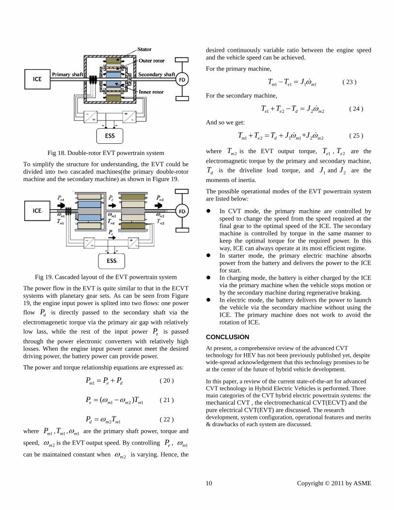
The representative of the EVT powertrain system is the double-rotor EVT system. Figure 18 shows the system configuration, which consist of two concentrically arranged electric machines. The two machines are mechanically coupled by a common shaft and electrically connected via two power converters. The primary double-rotor machine and the secondary outer-rotor machine are mechanically coupled by a common shaft and electrically connected via two converters. The ICE shaft is connected to the inner rotor and the final driveshaft is connected to the outer rotor(also known as interrotor).
10 Copyright © 2011 by ASME
Fig 18. Double-rotor EVT powertrain system
To simplify the structure for understanding, the EVT could be divided into two cascaded machines(the primary double-rotor machine and the secondary machine) as shown in Figure 19.
Fig 19. Cascaded layout of the EVT powertrain system
The power flow in the EVT is quite similar to that in the ECVT systems with planetary gear sets. As can be seen from Figure 19, the engine input power is splited into two flows: one power
flow dP is directly passed to the secondary shaft via the
electromagenetic torque via the primary air gap with relatively
low lass, while the rest of the input power eP is passed
through the power electronic converters with relatively high losses. When the engine input power cannot meet the desired driving power, the battery power can provide power.
The power and torque relationship equations are expressed as:
1m e dP P P ( 20 )
1 2 1( )e m m mP T ( 21 )
2 1d m mP T ( 22 )
where 1mP , 1mT , 1m are the primary shaft power, torque and
speed, 2m is the EVT output speed. By controlling eP , 1m
can be maintained constant when 2m is varying. Hence, the
desired continuously variable ratio between the engine speed and the vehicle speed can be achieved.
For the primary machine,
1 1 1 1m e mT T J ( 23 )
For the secondary machine,
1 2 2 2e e d mT T T J ( 24 )
And so we get:
1 2 1 1 2 2+m e d m mT T T J J ( 25 )
where 2mT is the EVT output torque, 1eT , 2eT are the
electromagnetic torque by the primary and secondary machine,
dT is the driveline load torque, and 1J and 2J are the
moments of inertia.
The possible operational modes of the EVT powertrain system are listed below:
In CVT mode, the primary machine are controlled by speed to change the speed from the speed required at the final gear to the optimal speed of the ICE. The secondary machine is controlled by torque in the same manner to keep the optimal torque for the required power. In this way, ICE can always operate at its most efficient regime.
In starter mode, the primary electric machine absorbs power from the battery and delivers the power to the ICE for start.
In charging mode, the battery is either charged by the ICE via the primary machine when the vehicle stops motion or by the secondary machine during regenerative braking.
In electric mode, the battery delivers the power to launch the vehicle via the secondary machine without using the ICE. The primary machine does not work to avoid the rotation of ICE.
CONCLUSION
At present, a comprehensive review of the advanced CVT technology for HEV has not been previously published yet, despite wide-spread acknowledgement that this technology promises to be at the center of the future of hybrid vehicle development.
In this paper, a review of the current state-of-the-art for advanced CVT technology in Hybrid Electric Vehicles is performed. Three main categories of the CVT hybrid electric powertrain systems: the mechanical CVT , the electromechanical CVT(ECVT) and the pure electrical CVT(EVT) are discussed. The research development, system configuration, operational features and merits & drawbacks of each system are discussed.
11 Copyright © 2011 by ASME
REFERENCES 1. Hofman, T., et al., Design of CVT-Based Hybrid
Passenger Cars. Vehicular Technology, IEEE Transactions on, 2009. 58(2): p. 572-587.
2. Miller, J.M., Propulsion Systems for Hybrid Vehicles. 2003, London, United Kingdom: The Institution of Engineering and Technology 472.
3. http://sycomoreen.free.fr/syco_english/moteurs_pompes_problematique_constat_eng.html. [cited.
4. http://www.crzforum.com/forum/engine-battery-discussion/777-hondas-ima-breakdown.html. [cited.
5. http://world.honda.com/automobile-technology/CVT/detail/. [cited.
6. http://www.roadandtravel.com/roadtests/reviews/2003roadtests/hondacivichybrid.htm. [cited.
7. www.plugincenter.net/wp-content/uploads/.../05_-_Andy_Frank_PhD.pdf. [cited.
8. A.W. Brown, J.v.R., A.A. Frank. The Design of an Inline GCI Chain CVT for Large Vehicles. in 2004 International Continuously Variable and Hybrid Transmission Congress. 2001.
9. Lin, H., et al. A novel continuously variable transmission flywheel hybrid electric powertrain. in Vehicle Power and Propulsion Conference, 2008. VPPC '08. IEEE. 2008.
10. Xiaolan AI, M.T., Anderson Scott An electro-mechanical infinitely variable speed transmission, in Proceedings of the 2004 SAE World Congress. 2004.
11. Miller, J.M., Hybrid electric vehicle propulsion system architectures of the e-CVT type. Power Electronics, IEEE Transactions on, 2006. 21(3): p. 756-767.
12. Jeffrey Wishart, Y.L.Z., Zuomin Dong Review of multi-regime hybrid vehicle powertrain architecture. International Journal of Electric and Hybrid Vehicles 2008 - Vol. 1, No.3 pp. 248 - 275, 2008.
13. http://www.sandyblogs.com/techconnect/2011/01/the-chevrolet-volt-hits-the-road.html. [cited.
14. Conlon and Brendan, Comparative analysis of single and combined hybrid electrically variable transmission operating modes. SAE transactions, 2005(6): p. 11.
15. Tim, M.G., Defining the General Motors 2-Mode Hybrid Transmission, in 2007 SAE World Congress. 2007.
16. Namdoo Kim, R.C., Forrest Jehlik and Aymeric Rousseau, GM Tahoe HEV Model Development in
PSAT. SAE 2009-01-1307, World Congress, April 2009
2009. 17. Chau, et al., Emerging energy-efficient technologies
for hybrid electric vehicles. 2007, New York, NY, ETATS-UNIS: Institute of Electrical and Electronics Engineers. 15.
18. Eriksson, S. and C. Sadarangani. A four-quadrant HEV drive system. in Vehicular Technology Conference, 2002. Proceedings. VTC 2002-Fall. 2002 IEEE 56th. 2002.
19. Hoeijmakers, M.J. and J.A. Ferreira, The electric variable transmission. Industry Applications, IEEE Transactions on, 2006. 42(4): p. 1092-1100.
20. Shumei, C., C. Yuan, and C.C. Chan. A Basic Study of Electrical Variable Transmission and Its Application in Hybrid Electric Vehicle. in Vehicle Power and Propulsion Conference, 2006. VPPC '06. IEEE. 2006.
21. Kessels, J.T.B.A., D.L. Foster, and P.P.J. van den Bosch. Integrated powertrain control for hybrid electric vehicles with electric variable transmission. in Vehicle Power and Propulsion Conference, 2009. VPPC '09. IEEE. 2009.
22. Yongchang, D., et al. HEV system based on electric variable transmission. in Vehicle Power and Propulsion Conference, 2009. VPPC '09. IEEE. 2009.
23. Yubin, W., et al. Design and analysis of double-stator permanent magnet brushless motor for hybrid electric vehicles. in Electrical Machines and Systems, 2008. ICEMS 2008. International Conference on. 2008.
24. Feng, C., C. Shumei, and C. Shukang, Performance analysis of double-stator starter generator for the hybrid electric vehicle. Magnetics, IEEE Transactions on, 2005. 41(1): p. 484-487.