jac light truck hfc1040
TRANSCRIPT

Thanks for your using JAC trucks!Before your using JAC trucks, please read this operating specification carefully and operate the trucks according to thespecification to bring JAC trucks' excellent performance into full play and keep the trucks in a good running state in along time!JAC trucks are developed and produced jointly by Anhui Province Automobile Research Institute and Anhui JianghuaiAutomobile Co., LTD. As well as the road conditions are taken to fully condition, the domestic and overseas modern de鄄sign and producing technique of body and chassis are absorbed and adopted to let JAC trucks bear good smoothnessand possibility, safe and reliable brake, easy and light control, convenient usage and maintenance.As a result of continuous progress in the technique, JAC trucks are also innovated and improved. All the diagrams anddata in the specification are based on the latest material when compiling. We would not inform you after making somemodification on it. Please forgive us for it.For the reason of hastiness, there may be some defect in it, and we are honored to receive your suggestion and advice.The technology consultation telephone number: 0551-2296374The service consultation telephone number: 0551-2296361Anhui Jianghuai Automobile Co.
ANHUI JIANGHUAI AUTOMOBILE CO., LTD.May. 2008
Preface

Notice! Please read these following items carefully before using JAC trucks!玉援As regards JAC trucks, please pay attention to these following items:
1.It is forbidden to make refitting and adding equipment without our permission, especially on the electric appliance,
brake, steering and so on that will affect the safety system of the products.
JAC will not take upon herself the loss owing to your refitting and adding equipment without our permission!
2.when using JAC products, please make timely maintenance and service according to the service manual to bring the
good performance of your loving truck into full play.
3.Please be sure to go to special repair shop of JAC for service if finding problems in using; please use genuine parts of
JAC if needing to change parts. JAC will not take upon herself the loss owing to your not using genuine parts.
4.Any consumer that uses JAC complete vehicle or chassis is forbidden to change its product identification and name鄄
plate, or the consumer will be responsible for it.
域援As regards the special purpose chassis of JAC, please pay attention to the following items:
1. It is forbidden to lengthen or widen the frame of JAC without JAC's permission, or you will take upon yourself the loss
for it.
2.As regards the refitting on JAC special purpose chassis, all the refitting companies should not make the refitted mod鄄
els be contradict with the traffic regulations and the relevant rules of the nation, or JAC will not be responsible for it.
玉尧 Use of vehicle 1
域尧Engine 21
芋尧Chassis 29
IV尧Electrical equipment 55
吁尧Vehicle service and maintenance 61
遇尧Trouble shooting 65
喻尧Automotive model table of trucks 85
峪尧Appendix 89
Main files alone with the vehicle 94
Contents

1
玉. Use of vehicle(玉). Use of instruments and apparatuses in the cab
(域). Use of components in the cab
(芋). Start and running of vehicle

( 玉 ). Use of instrumentsand apparatuses in the cab1. Integrated switch and instru鄄ment clusterIntegrated switch (figure below)which is composed of steering shaftlock seat尧ignition start lock andcombination switch lies underneaththe steering wheel.
1) Ignition switchIgnition switch is on the right side ofintegrated switch. It has four func鄄tions: LOCK尧ACC尧ON尧START. Whenthe key is on the 'LOCK' position,the ignition switch has been connect鄄ed to the power source and thelockup of steering gear has beendisengaged. Turn the key to 'ACC'position clockwise, the circuit of ac鄄cessories like radio and tape playercan be connected. Turn to the 'ON'position, and the instrument circuit isconnected. If keep on turning until tothe 'START' position, the engine canbe started. You should unlash thehandle of the key immediately afterthe engine started. And the key canreturn to the 'ON' position by the ac鄄
tion of spring. The schematic dia鄄gram of ignition switch is as follows.
2) Combination switch ( left controlhandle)
left control handle
schematic diagram of ignition switchcombinationswitch
ignition switch
schematic diagram of integrated switch
2
HFC1048series trucks
Combination switch is under thecontrol of the multifunction handle,which lies in the lower left and inferi鄄or place of the steering wheel. It cancontrol small light尧headlight尧head鄄light dimmer and turning to the left orthe right by two different movementmodes. The symbol and function ofthe combination switch is as follows:淤 The OFF symbol indicates thatsmall light and headlight do not light.(But at this time the high beam canlight if you put up the handle.)于 The symbol is the indica鄄tion of small light. Turn the controlhandle clockwise by 30毅 ,and thefront尧rear small lights and the instru鄄ment light can light.盂 The symbol is the indica鄄
tion of headlight. Keep on the turningof the left control handle clockwiseby 30毅 , the front headlight尧the rearsmall light and the instrument lightcan light.榆 The symbol is the indica鄄tion of steering. Forward and back鄄ward motion of the control handlecan operate the left and right turninglamp and the turn light indicator inthe instrument panel. Push the con鄄trol handle forward in the horizontaldirection, the right turning lamp lightsand there has the indication of turn鄄ing right in the instrument panel. Onthe other hand, pull the control han鄄dle backward, the left turning lamplights and there has the indication ofturning left in the instrument panel. If
the control handle is in the middleposition, then there has no indicationof turning.虞 Dimmer of headlight: Lift the leftcontrol handle upwards gently anddo the 'uplift -looseness' motion, itcan control the dimmer function ofthe headlight. Uplift the handle once,high beam headlamp lights; loosethe handle, it goes out. Repeatingthe above action can control thework status of the high beam head鄄lamp to obtain the purpose of dim鄄mer function when overtaking orpassing in night.
3
4
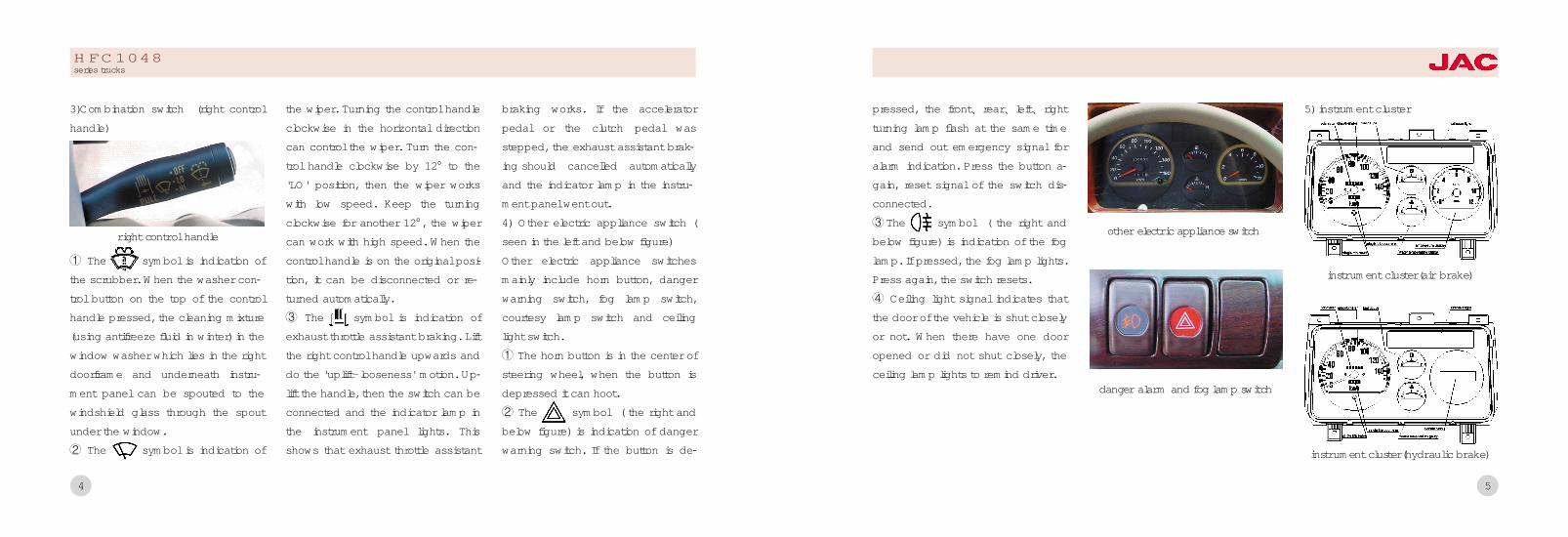
3)Combination switch (right controlhandle)
淤 The symbol is indication ofthe scrubber. When the washer con鄄trol button on the top of the controlhandle pressed, the cleaning mixture(using antifreeze fluid in winter) in thewindow washer which lies in the rightdoorframe and underneath instru鄄ment panel can be spouted to thewindshield glass through the spoutunder the window.于 The symbol is indication of
the wiper. Turning the control handleclockwise in the horizontal directioncan control the wiper. Turn the con鄄trol handle clockwise by 12毅 to the'LO' position, then the wiper workswith low speed. Keep the turningclockwise for another 12毅 , the wipercan work with high speed. When thecontrol handle is on the original posi鄄tion, it can be disconnected or re鄄turned automatically.盂 The symbol is indication ofexhaust throttle assistant braking. Liftthe right control handle upwards anddo the 'uplift-looseness' motion. Up鄄lift the handle, then the switch can beconnected and the indicator lamp inthe instrument panel lights. Thisshows that exhaust throttle assistant
braking works. If the acceleratorpedal or the clutch pedal wasstepped, the exhaust assistant brak鄄ing should cancelled automaticallyand the indicator lamp in the instru鄄ment panel went out.4) Other electric appliance switch (seen in the left and below figure)Other electric appliance switchesmainly include horn button, dangerwarning switch, fog lamp switch,courtesy lamp switch and ceilinglight switch.淤 The horn button is in the center ofsteering wheel, when the button isdepressed it can hoot.于 The symbol ( the right andbelow figure) is indication of dangerwarning switch. If the button is de鄄
right control handle
HFC1048series trucks
5
pressed, the front尧 rear尧 left尧 rightturning lamp flash at the same timeand send out emergency signal foralarm indication. Press the button a鄄gain, reset signal of the switch dis鄄connected.盂 The symbol ( the right andbelow figure) is indication of the foglamp. If pressed, the fog lamp lights.Press again, the switch resets.榆 Ceiling light signal indicates thatthe door of the vehicle is shut closelyor not. When there have one dooropened or did not shut closely, theceiling lamp lights to remind driver.
5) instrument cluster
danger alarm and fog lamp switch
other electric appliance switch
instrument cluster(air brake)
instrument cluster(hydraulic brake)

7
(域). Use of components inthe cabCabBrief description of the structureThe driver cab is forward control cabwith full metal enclosed construction.Window glass adopts panoramiccamber windshield. In order to im鄄prove the comfort, side panel withlarger upside width and raised -roofcab have been adopted. Thereforethe interior space of the cab can bemore commodious and comfortable.Effective measures have taken in re鄄duce noise尧 heat insulation尧 soundinsulation and sealing. For instances,the section of roof forehead is en鄄closed and strengthening rib is e鄄quipped on the roof. There have
three asbestos heat insulating mat鄄tress on the upside of the engine.Sealing of the door is double skinconstruction. At the aspect of safety,softening has done to the main parts,which can appear knocking easilywith passengers.
The air condition system(chooseto pack)1.Brief introductionThe automobile air -conditioner andthe automobile instrument panel is anintegral body which have cold airand warm air machine. It has manyuseful functions , or example ,tomaking cold air ,warm air and to re鄄moving frost . The air -conditionersystem has four high and low steps ,
so the customer can choose whatyou like ,for example , can choosethe same way to sending wind.
2.Operation2.1 To operating the engine2.2 To press the switch for the air -conditioner , then operating the airvolume .The switch has four grades ,from left to right ,so the air volume ofair -conditioner will be more andmore strong.
6
Indicators (figure in the above page):淤 Turn indicator lamp( ) whenthe turning control handle is on theleft (right) turning position, left (right)turning indicator lamp flashes. If thewarning switch is pressed, the leftand right turning indicator lampsflash at the same time.于 High beam indicator lamp( )indicates that the headlamp is in the
status of high beam or not. When theheadlamp is on the high beam sta鄄tus, the indicator lamp lights.盂 Fuel warning lamp( ): fuel levelalarm, when fuel is in shortage, fuelalarm lamp lights.榆 Parking brake indicator lamp渊 冤院when pull up the parking brakehandle,the indicator lamp lights.虞 Exhaust assistant brake indicatorlamp渊 冤院when exhaust assistantbraking operates, the indicator lamplights. When exhaust assistant brakeis disconnected, the indicator lampgoes out.愚 Oil pressure indicator lamp渊 冤院indicates low - pressure warning ofengine oil pressure. When oil pres鄄sure is lower than 0.08-0.1Mpa , the
oil pressure indicator lamp lights.When oil pressure is higher than thevalue, the oil pressure indicator lampgoes out.舆 Braking fault indicator lamp渊 冤院when braking fluid is not enough, theindicator lamp lights.余 Exhaust assistant brake indicatorlamp 渊 冤院when exhaust assistantbraking operates,the indicator lamplights. When exhaust assistant brakeis disconnected,the indicator lampgoes out.俞 Fog lamp indicator lamp渊 冤院when braking fluid is not enough, theindicator lamp lights.逾 Small light indicator lamp渊 冤院When they work袁he indicator lamplights.
1尧turn left 2尧high beam 3尧turn right4尧fuel alarm 5尧parking brake6尧charging 7尧oil pressure alarm8尧braking fault 9尧exhaust assistantbrake 10尧fog lamp 11尧small light
indicators
HFC1048series trucks

8
2.3 To operating air -conditionerswitches 5,then the compressor be鄄gins to work at this time .The wholesystem will be colder.2.4 Using the cold wind , please putthe temperature adjusting handle 3 tothe COOL position .Using the warmwind ,you should put in the HOT po鄄sition .To changing the wind-position,choose the handle 2 can make thecold (warm) breeze never lead withdirection .If you want to using thewarm wind ,you should be closeswitch of the air condition.2.5 To turning the natural wind con鄄version , then pressing the handle1can make the natural wind fromoutside of the car.
3.Caution3.1 You should be avoid the handlein the most cold position when usingt he air-conditioner in order to pre鄄vent evaporate the machine fromfrost.3.2 Do not park the cars under thesun .3.3 To using air -conditioners, youshould be close windows and doorsof the cab.3.4 To cleaning the condenser , youshould be wash with the compressedair or cold water ,do not wash itstrictly with the hot water or steam.3.5 The air-conditioner does not usein winter , however ,you should berevolve compressor once a weekabout five minutes .In order to main鄄
tain the air -conditioner for normalworked.3.6 If you want to use the air heater ,the temperature degree of engineshould reach to 70 益s above .At 0益s the automobile should not park inthe cool environment, it should beuse antifreeze fluid, in order to pre鄄venting frost radiator and air heater.3.7 If you do not know the preven鄄tions about the air -conditioner , donot switch it , the in order to preventresults in trouble.The top of cab's ventilating devicewhich has two ways for it .One is ex鄄terior air with indoor ,another one ishouse airiness .
i. Leading exterior air(1) Clockwise the rotary-knob on the
HFC1048series trucks
9
top of cab that you definite the topcab is closed.(2) Turn on the switch to "IN" thenturn on the rotary knob to "OPEN" .
ii. Indoor airiness(1) Clockwise the rotary knob to clos鄄ing the ventilator louver.(2) Turn to the switch to "out "which isthe exhaust gear position.
Door1) The cab door, which have three-
step opening, can improve the con鄄venience for passengers getting onor off. The opening angle of the doorcan be 30o尧 57o and 90o. The for鄄mer two angles are partially openand the last angle is full open. On allthe three positions, the door can bein stable condition. outside door handle
lock button

10
2) Outside door handlePull out the outside door handle, andthen the door can be opened. Insertthe starting switch key into the doorlock and turn, the door can belocked.3) The door can be locked outsidewithout the key. First press down thelock button (figure in the abovepage) at the inner side of the door tothe fixed position, then pull the out鄄side door handle outwards and atthe same time close the door.4) Pull out the inside door handle,and the door can be opened. Afterclosing the door, the door can belocked if the lock button is presseddown.
Cab seatCab seat can be classified as driverseat尧 assistant driver seat and rearrow seat. Driver back seat adopts up鄄right seat. The angle of backrest andthe fore-and-aft position of seat canbe adjusted. The maximum ad鄄justable angle of the backrest is 56o.The maximum adjustable distance ofthe seat is 160 mm. The seat adjustsystem is shown in the right figure.When vehicle is in the progress ofmaintenance, please clean the trackassembly of the driver seat, recoat thelithium base grease, and tighten alljoint nuts again. If found that the cabtrack slide seat has shaking or blockbecause of distortion, it should be re鄄paired or replaced with components.
HFC1048series trucks
11
Cab tilt lock mechanism
Brief of the structureThe cab has turnover functions , alsohas turnover and lock up organiza鄄tion . The turnover was composed oftorsion bar, supporting -axle,
cab'srear bracket and so on.The cabto turnover is used by torsion power.Lock up system is composed ofright/left lock unit ,turnover lock unit ,short pull rod ,long pull rod ,rearbracket of cab and so on .All of thisis to lock the cab too tightly.(as pic鄄ture)Please read the tilting notes on theleft door of the cab and on the upperflange of the wheel seriously beforetilting the cab. The notes are shownin the upper figureUse and maintenanceIn order to tilting the cab reliably andrunning the vehicle safely, pleasepay attention to following contents.渊1冤Cab tilting method and relativeattentive notices.
淤 When the vehicle is stopped onthe horizontal road, you should makesure that there has enough spacearound the cab before tilting. Or else,the cab may be damaged while tilt鄄ing.
1.chuck rod2.overturn rod3.safe locking hook
notice
schematic diagram ofcab tilt locking device
support rod assembly

12
于 Pull up the parking brake; pushthe shifting lever into the neutral posi鄄tion to avoid the self -sliding of thevehicle.盂 The cab door must be fastenedup. You should take all goods on theinstrument panel尧 seat and flooraway to avoid the damage of thedoor and the front windshield.榆 First disengaged the lockingfunction of the cab locking mecha鄄nism when tilting the cab.虞 After the locking function disen鄄gaged, hold the tilting rod with handand pull up the safety lock hook atthe same time to avoid the suddenuplift of the cab.愚 Raise the cab slowly until it is tilt鄄ed to the maximum position, then
lock it reliably with lock arm on therear bracket. It is shown in the rightfigure.舆 When lowering the cab down, firsthold the tilting rod and disengagethe locking function of lock arm onthe rear bracket, then lower the cabdown slowly. After the safety locklocked, fasten the locking mecha鄄nism.渊2冤Inspection and maintenance淤 Check periodically the rubber padassemblies which are used tostrengthen the front尧rear support, iffind damaged, it should be replacedinstantly.于 Check periodically the locking sit鄄uation of the locking mechanism, ifinvalidation of locking function found,
it should be repaired or replaced im鄄mediately.盂 If felt arduous when tilting up thecab or heavy when dropping downthe cab, the torsion rod is invalid. Re鄄place the torsion rod.榆 When repairing the chassis, be鄄fore removing of the cab, disengagethe force of the torsion rod and op鄄erate with following steps.a. Disengage the locking state, andtilt up the cab to the utmost position.b. Remove the shaft pin connectedthe rear support rod and the baseboard support of the cab.c. Push the cab forwards for someangle until the bolt on the torsion rodarm can be loosened.d. After the bolt removed, the torsion
HFC1048series trucks
13
rod cannot work. Now the cab canbe removed ( The torsion rod can notbe pulled out).Note: The above -mentioned workmust be done by three persons atleast because two or three personscannot push the cab forward afterthe force of the torsion rod is disen鄄gaged.虞 Before reverting the cab to the o鄄riginal position, return the force of thetorsion rod and operate with follow鄄ing steps:a. Put the tooth part of the splinewhich is cut at the bottom on oneend of the torsion rod in alignmentwith '1' position on the support axletube and the spline tube, and insertthe torsion rod into the support axle
tube ( for the rod which is pulledout).b. After mount the cab with supportaxle tube and the left尧 right brackettogether to the frame, put the '1' ofhub splines on the torsion rod inalignment with the spline tooth whichis cut at the bottom on the other endof the torsion rod, cover the hubsplines on the torsion rod and insertthe spline axle tube into the rightbracket in the cab.c. Tilt the cab forwards until the bolthole on the torsion rod arm aimed atthe screwed hole on the right bracketin the cab, screw the bolt and tightenit.d. Put the cab down slowly, andcheck whether the cab is on the
state of suspending at the horizontaldirection after dropped down. If nor鄄mally, then lock the cab.愚 If find invalidation of the torsionrod, when replacing, operates ac鄄cording to 榆 虞.
(芋). Starting and running ofthe vehicle1. Starting of the vehicle1冤Starting of the engineWhen starting the engine, put theshift bar on the neutral position, turnon the ignition switch, check horns尧instruments on the instrument panel尧turning lamps尧 braking lamps尧 theangle and position of the rear viewmirror.淤 Routine start
14
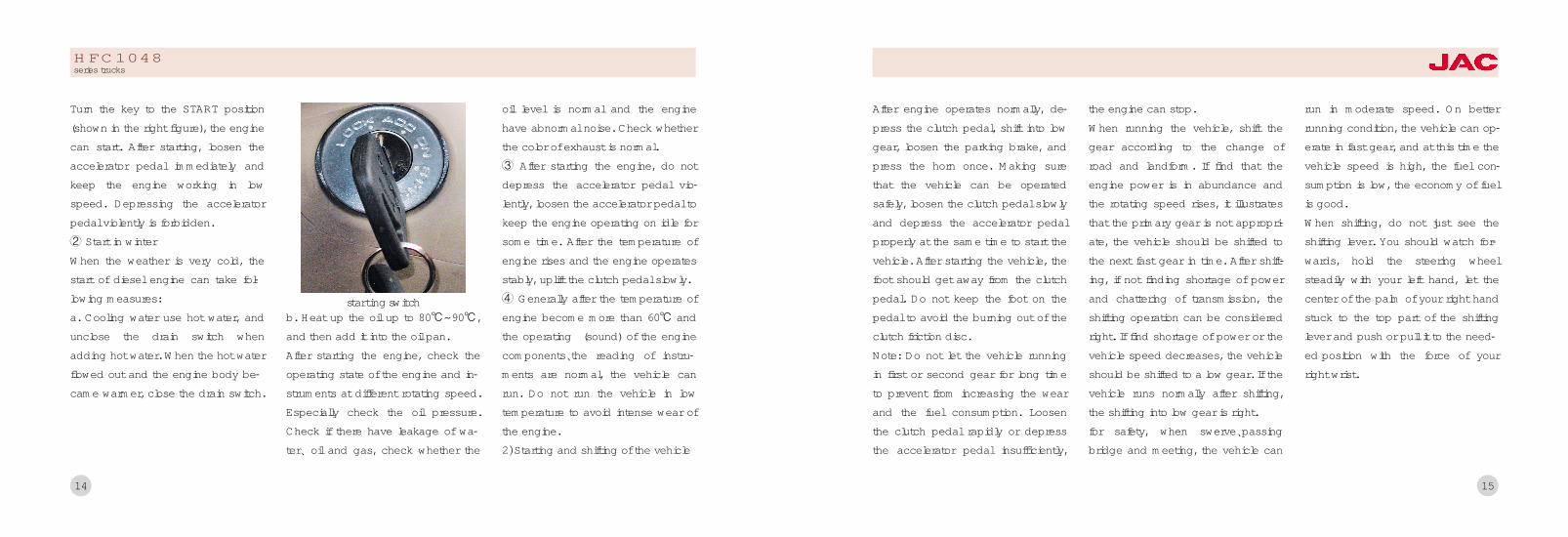
Turn the key to the START position(shown in the right figure), the enginecan start. After starting, loosen theaccelerator pedal immediately andkeep the engine working in lowspeed. Depressing the acceleratorpedal violently is forbidden.于 Start in winterWhen the weather is very cold, thestart of diesel engine can take fol鄄lowing measures:a. Cooling water use hot water, andunclose the drain switch whenadding hot water. When the hot waterflowed out and the engine body be鄄came warmer, close the drain switch.
b. Heat up the oil up to 80益耀90益 ,and then add it into the oil pan.After starting the engine, check theoperating state of the engine and in鄄struments at different rotating speed.Especially check the oil pressure.Check if there have leakage of wa鄄ter尧 oil and gas, check whether the
oil level is normal and the enginehave abnormal noise. Check whetherthe color of exhaust is normal.盂 After starting the engine, do notdepress the accelerator pedal vio鄄lently, loosen the accelerator pedal tokeep the engine operating on idle forsome time. After the temperature ofengine rises and the engine operatesstably, uplift the clutch pedal slowly.榆 Generally after the temperature ofengine become more than 60益 andthe operating (sound) of the enginecomponents尧the reading of instru鄄ments are normal, the vehicle canrun. Do not run the vehicle in lowtemperature to avoid intense wear ofthe engine.2冤Starting and shifting of the vehicle
starting switch
HFC1048series trucks
15
After engine operates normally, de鄄press the clutch pedal, shift into lowgear, loosen the parking brake, andpress the horn once. Making surethat the vehicle can be operatedsafely, loosen the clutch pedal slowlyand depress the accelerator pedalproperly at the same time to start thevehicle. After starting the vehicle, thefoot should get away from the clutchpedal. Do not keep the foot on thepedal to avoid the burning out of theclutch friction disc.Note: Do not let the vehicle runningin first or second gear for long timeto prevent from increasing the wearand the fuel consumption. Loosenthe clutch pedal rapidly or depressthe accelerator pedal insufficiently,
the engine can stop.When running the vehicle, shift thegear according to the change ofroad and landform. If find that theengine power is in abundance andthe rotating speed rises, it illustratesthat the primary gear is not appropri鄄ate, the vehicle should be shifted tothe next fast gear in time. After shift鄄ing, if not finding shortage of powerand chattering of transmission, theshifting operation can be consideredright. If find shortage of power or thevehicle speed decreases, the vehicleshould be shifted to a low gear. If thevehicle runs normally after shifting,the shifting into low gear is right.for safety, when swerve尧passingbridge and meeting, the vehicle can
run in moderate speed. On betterrunning condition, the vehicle can op鄄erate in fast gear, and at this time thevehicle speed is high, the fuel con鄄sumption is low, the economy of fuelis good.When shifting, do not just see theshifting lever. You should watch for鄄wards, hold the steering wheelsteadily with your left hand, let thecenter of the palm of your right handstuck to the top part of the shiftinglever and push or pull it to the need鄄ed position with the force of yourright wrist.

16
2.Running尧 swerve尧 turnaro -und尧 backing and braking ofthe vehicle1) RunningKeep enough distance to the forego鄄ing vehicle when running on flatroad. Select vehicle speed accordingto the vehicle model尧mission andconcrete condition of road, generallyselect the speed of 50耀70 km/h.Let the vehicle running in the first orsecond gear when starting, upgrad鄄ing under heavy load and running onbumpy road or on the road havingobstacles. But the vehicle can notrunning in the first or second geartoo long in normally running. Whenupgrading with heavy load, shift theshifting lever into low gear to avoid
overloading of the engine.When running, do not increase or de鄄crease the vehicle speed abruptlyand not shake the steering wheelwithout reason, listen whether there isabnormal noise or not, check thereading and indicator lamp of all in鄄struments for normalization. If findabnormal noise or abnormal events,stop the vehicle immediately andcheck it, take necessary adjustmentand repair.When downgrading, do not stall theengine. When downgrading steepramp, shift the shifting lever into lowgear and take braking operation atintervals to avoid the over fast of thevehicle speed.When running across shallow river or
loblolly, prevent the water from enter鄄ing into air intake lines of the engine尧rear axles and transmission case.Check rear axles and transmissioncase for entering water after pad鄄dling. If find water, drain it and addgear oil with specified quantity. Afterpaddling, the vehicle can not run inhigh speed. You should depress thebraking pedal every now and then toresume the braking performance assoon as possible.When running on the ice or snowroad, run with steady speed. Do nottake emergency braking and not turnthe steering wheel fiercely to avoidskidding danger. Keep long safetydistance from the foregoing vehicle.When running in heavy rain, drive the
HFC1048series trucks
17
vehicle more carefully to avoid de鄄creasing the braking performance ofthe brake because of moist. Do nottake emergency braking operation toavoid the danger of skidding.2) SwerveSwerve of the vehicle produces cen鄄trifugal force which can be biggerwhen the vehicle speed becomeshigher. The force can bring turningover in the transverse direction inserious condition. Therefore, at the50耀100 meters position before turn鄄ing the vehicle, you should ring thehorn尧 turn on the turning lamp andreduce the vehicle speed. Whenrunning on the freezing and muddyroad or in the weather of heavy rain尧fog尧 wind尧 sand, reduce the vehicle
speed to less than 10 km/h, swervethe vehicle slowly alongside the rightside of the road. When swerving, turnthe steering wheel uniformly accord鄄ing to the situation of road, theswerving track should be transitedsmoothly, the turning motion shouldnot be too great or too small. Do notturn or return the steering wheelsuddenly. Try your best to avoid tak鄄ing braking operation while turningthe steering wheel, especially emer鄄gency braking.When steering, if found skidding offront wheels, put up the acceleratorpedal and turn the steering wheel inthe contrary direction; if found skid鄄ding of rear wheels, turn the steeringwheel properly along the skidding
direction, and after the skiddingstops, correct the running direction.3) Turning aroundWhen turning around for 180毅, selectthe square尧large -scale crossing orflat broad road which have little traf鄄fic flux and turn around the vehicle ata time along the running direction. Atthe 50耀100 meters position in front ofthe turning spot, reduce the vehiclespeed, shift into low gear and sendout the turning around signal.When turning around with runningforwards and backwards, first sendout the turning around signal, reducethe vehicle speed and run towardsthe right side of road. When ap鄄proaching the preset spot for turningaround, observe the situation of road,

18
turn the steering wheel to the left ex鄄treme position rapidly and let the ve鄄hicle running to the left side of roadslowly. When approaching the road鄄side, return the steering wheelrapidly. After observing the situationbehind the vehicle, start and turnaround the vehicle, turn the steeringwheel to the right extreme position atthe same time. When approachingthe roadside, return the steeringwheel rapidly and stop the vehicle. Ifthe turning around operation can notbe done once time, repeat the aboveoperations.4) BackingThe operation of shifting into reversegear or shifting from reverse gear toonward gear can be done after the
vehicle is stopped completely. Aftershifting into the reverse gear, theback -up lamp lights. The vehiclespeed must be less than 5 km/hwhen backing. If the driver can notdiscern the situation behind the ve鄄hicle because the vehicle is loadingor other reasons, the backing oper鄄ation must be commanded by oneperson who is outside the vehicle.Do not back the vehicle blindly.5) Parking of the vehicle and stop ofthe engineWhen preparing to park the vehicle,the vehicle speed reduces or the ve鄄hicle slides out of gear and indicateswith turning lamp. After the vehicleparked, pull up the parking brakelever. If the vehicle must be parked
on the road for some reason, parkthe vehicle near the roadside and notpark the vehicle on the running lane.Under the exceptional condition likebreaking down in the middle of road,two caution plates should be placedon the position of 200 meters in frontof and behind of the vehicle.Avoid parking on the ramp. If thevehicle must be parked on the ramp,pull up the parking brake lever to theextreme position, shift into low gearand block the vehicle with triangularchocks or stones to prevent it fromsliding. Note: Make sure that theparking brake can work reliably whenparking on the ramp, at the sametime turn on the emergency warningsignal indicator lamp.
HFC1048series trucks
19
After parking, especially after the en鄄gine operates with heavy load, donot stall the engine immediately, butkeep the engine operating in lowspeed for several minutes. After thetemperature of water decreases lessthan 70益, then stop the engine.When parking midway in winter, takethe heat preservation and antifreez鄄ing measures for the engine. Preventthe oil tank from insolation in sum鄄mer.After the vehicle runs a day, routineservice and inspection should bedone on the entire vehicle.

21
域.Engine(玉). Inlet air尧 exhaust systems
(域). Cooling system
(芋). Accelerating transmission system
(郁). Fuel supply system

22
Notice院The details of the engine structure尧 assembling尧 adjustment尧 using and maintenance can be consulted in the oper鄄ating specification of relevant engines.The position of the engine cardCause院The card of engine is on the top cylinder head or on the side of engine .It writes the model number of engine ,sequence number ,declared power ,declared speed and the factory date .Pay attention to find it in order to using itclearly and convenience.(as picture)
HFC1048series trucks
23
(玉). Inlet air尧 exhaust sys鄄tems1. Brief description of the struc鄄tureInlet system includes air inlet pipeassembly尧 air filter assembly尧 intakemanifold. Exhaust system includesexhaust pipe尧 muffler and exhausttailpipeUse and maintance院1) The service life of the engine hasgreat relationship to the workmanshipof the air filter. Absolutely forbid thatthe engine works without air filter oron the condition that the air filter isdisabled. Taking the intake openingof air filter as the original intake open鄄ing is forbidden.
2) For every 1000km running, checkthe inlet and exhaust manifold for thefollowing:a. Check nuts for looseness, whentightening the nut on the inlet andexhaust manifold, the torsion forceshould be equable, or else the airleakage can occur.b. Check the inlet and exhaust mani鄄fold for crack and hole, check thegasket for damage and erosion, iffound, replace it with a new one.
Air filterThe function of air filter is to filter outthe dust and the sand in the air en鄄tered into the engine.Air filter is cyclone dust gathering aircleaner with paper filter element. Af鄄ter external air enters into the air filter
through the air inlet pipe, larger dustparticle can be separated from theair by the function of cyclone vane,then can be thrown into the dustgathering plate, the separated airkeep on moving and enter into thecylinder by the filtering function ofthe paper element.For every 1000km running, checkand maintain the air filter. When run鄄ning in the condition of excessivedust, the running mileage interval forinspection and maintenance shouldbe shortened suitably.Cleaning of the air filter:1) Remove the dish-shaped nut fromthe end cover. Take away the endcover, remove the inner nut and takeoff the filter element assembly.

24
2) Clean the cover cap and the innerpart of the housing with dry andclean cloth.When cleaning, do not letthe moisture enter into the air filter.
3) To cleaning dust unloading valvein order to usage well .4) Tight and close the rubber ofconnected brake .5) Clean the air filter element: clearaway the dry dirt or dust with com鄄pressed air gun (air pressure shouldbe less than 690kpa),blow from theinner side of filter element towardsoutside. Do not clear away the dirt orthe dust with beating or knocking.
(域). Cooling system1.Brief description of the struc鄄tureCooling system is closed water cool鄄ing pressure cycle type. It is com鄄posed of radiator尧coolingfiuid尧ther鄄mostat尧 fan 尧bulge radiator and wa鄄ter inlet and outlet pipes of radiator.
The concrete structure and type ofthe cooling system components canbe consulted in detail in the operat鄄ing specification of relevant engines.
2.Using and maintenance of co-oling system1) Recommend using long effectiveantifreeze preservative liquid for cool鄄ing fluid. In the north, it can avoid thedamage of engine because of thefreezing of cooling fluid in winter; inthe south, it can increase the boilingpoint of cooling fluid in summer toavoid the damage of engine over鄄heating because of air resistance inhigh temperature.2) Before dispatch the vehicle everytime, check the liquid level in the ra鄄diator and in the bulge radiator, if
1尧cab 2尧vent hose (1) of the air filter3尧intermediate connecting pipe4尧connection board5尧vent hose of the air filter6尧right longitudinal member of the frame7尧air filter bracket8尧intake pipeline of the air filter9尧connecting hose 10尧air filter
schematic diagram of air filter
HFC1048series trucks
25
found it is not enough, add liquid tothe specified height.3) Drainage of cooling system. Incold region and in winter, without us鄄ing antifreeze preservative liquid, iflong time parking or receiving thevehicle everyday, the cooling systemmust be drained. And you shouldopen the water filler cap of the radia鄄tor to avoid the incomplete drainageof cooling water.4) After engine operating for longtime, furring can produce in thecooling water and it should becleaned in time. Clean it with follow鄄ing method: mix 700 耀800 gramcaustic soda and 150 gramkerosene, add the mixture liquid intothe cooling water, run in medium
speed for 5 耀10 minutes, then afterstopping for 10耀12 hours, restart theengine and run for 10 耀15 minutes.Then drain the aqueous solution andclean the cooling system withcleaned water.
3.Advertent proceedings in usinglong effective antifreeze preser鄄vative liquid1) Choose suitable antifreeze liquidaccording to the minimum tempera鄄ture of the region, if the minimumtemperature of the region is -25益 ,antifreeze liquid whose solidifyingpoint is -30益 should be chosen.2) When compensating antifreezepreservative liquid, choose the samemodel to avoid deposition.3) If find deterioration of antifreeze
preservative liquid, replace it entirelyat once. The color of antifreeze liquidis green or blue, if having deteriorat鄄ed, the color should be dull red be鄄cause of impurity infiltration.
To adjusting the degree of ten鄄sion of the fan belt1.The disadvantage of engine istighten or lax the fan belt .Before useit please read the operating specifi鄄cation .2.The way of adjustment :firstly toadjusting blots ,secondly to adjusting,third to adjusting the tight ofwedge -shaped belt .Using fingerpress way ,to pressing for 98/N .Thestandard of crankshaft pulley is 25要31mm .The standard of fan belt is7要8mm.

26
(芋) Accelerating transmis鄄sion system1.Brief description of the struc鄄ture
Accelerating transmission equipmentis composed of accelerator pedalmechanism尧 accelerator wire draw鄄ing and acceleration governor arm ofthe engine. It is shown in the figure inthe above page.When depress the pedal, drivingmedium of the mechanism pull thewire drawing, control the openingextent of the accelerator to increaseor decrease the speed1冤 Accelerator pedal mechanism:Accelerator mechanism take thenewest structure of ISUZU truck. Itoperates simply and reliably and hasaccelerating wire drawing and handthrottle wire drawing; the pedal is thestructure with injected molding and ithas the trait of convenient assem鄄
bling and little operating noise.2冤Accelerating wire drawing:It operates by the soft wire drawing.And it has traits of reliable structure尧convenient layout尧 little frictional re鄄sistance and stable transmission.3冤Hand throttle wire drawing:Using with the foot throttle can quick鄄en the preheating of the engine or in鄄crease the idling speed.
2.Using and adjustment1) Check the chucking position of thelinkage rod and the acceleratormechanism for rightness and reliabil鄄ity, check the direction of the wiredrawing for straight and check onthe cornering for smooth transition.2) The pedal should be depressedeasily and to the extreme position
1尧stalling wire drawing 2尧assemblyof accelerator mechanism and pedal3尧front floor of the cab4尧acceleration wire drawing5尧stalling oscillating arm of the engine6尧acceleration oscillating arm of theengine 7尧frame
schematic diagram of acceleratingtransmission equipment
HFC1048series trucks
27
without jamming. When releasing thepedal, it should be returned freely.3) When depressing the pedal, if thefree play is too big or the openingextent of the accelerator is not e鄄nough, adjust the position of bolts.
渊郁冤 Fuel supply system1.Brief description of the struc鄄tureFuel supply system is composed offuel tank尧 fuel filter尧 fuel pump尧fuelinlet line and fuel return line.The function of the fuel supply sys鄄tem is to inject the specified quantitydiesel fuel of specified pressure andgood atomization into the cylinder atthe correct time with definite intervalof injection according to the operat鄄ing requirement, and take good com鄄
pression ignition with the air rapidly.Its operating state has important in鄄fluence to the power and economyperformance of the engine.1) Coarse cleaner院the car's fuel pip鄄ing have a DX150T spin-on oil filter袁flow volume is 1.5L/min. It can transi鄄tion impurity and can separate waterand oil
2) Fuel tank:. The tank install the filtergauze inside the fuel filler port to pre鄄vent impurity of large particle enter鄄ing into the fuel tank, set oil drainplug on the bottommost position ofthe fuel tank to drain the deposit andwater on the bottom of tank whencleaning the fuel tank.
Using and maintenance of coar-se cleaner1冤To tight all the pipe line .2冤When the DX150Tprecipitator wor-ks for 1000/km and 200hours, to wa鄄terproofing.
diesel precipitator

29
芋尧Chassis渊玉冤Clutch
渊域冤Transmission
渊芋冤Drive shaft
渊郁冤Rear axle
渊吁冤Frame
渊遇冤Suspension set
渊喻冤Front axle
渊峪冤Steering system
渊御冤Brake system
渊愈冤Wheel & Spare wheel riser

31
lowed, or else, it can result in thedisability of the pedal尧 deficiency ofthe effective travel and incompleterelease of the clutch etc. So theclutch can not work normally. Thework of air bleeding should be com鄄pleted by two persons in the best,one person depress the clutch pedalin the cab, the other bleed the air inthe wheel cylinder. The schematicdiagram of air bleeding for the clutchwheel cylinder is shown .Take off the rubber cap of the airbleed screw on the wheel cylinder,link a plastic pipe on the air bleedscrew, put the other end of the pipeinto the container filled with brakefluid, depress the clutch pedal sever鄄al times, fill the master cylinder and
hydraulic pipeline with brake fluid,then loosen the air bleed screw, airbubble can be puffed from the oilring if there have air in the pipeline.Repeat the above-mentioned opera鄄tion until the air bubble disappear .
Maintenance and adjustmentLong time use or incorrect adjust鄄ment and incomplete air bleeding ofthe clutch can bring the halfway re鄄lease of the clutch, let the clutch onthe half contact state for long time,aggravate the wear of the clutchpressure plate and friction linings.The decrepitation尧 burnt and exfolia鄄tion of the friction lining, and theburnout of the release bearing alsocan result in the abnormal operationof the clutch. When maintenance, allkinds of clearance of the clutch mustbe adjusted. When doing the thirdmaintenance for the trucks ,you mustclean general/dispant cylinder andliquid reservoir tank ,then fill greaseto hole of disengaging shaft.
1尧release fork 2尧dust cover3尧copper washer 4尧wheel cylinder5尧wrench 6尧soft plastic pipe7尧container 8尧braking
渊玉冤Clutch1.Brief description of the struc鄄tureThe clutch equipped for this seriestruck is single -plate dry type di鄄aphragm spring clutch, outside di鄄ameter of the driven plate is 椎254.The hydraulic control unit of theclutch is composed of the clutchpedal尧oil storage cup尧 release cylin鄄der (master cylinder)尧 wheel cylinderand oil pipe. It is shown in the belowfigure.Adjustment of the clutch operat鄄ing system1冤Adjust the limit screw of the clutchpedal (below figure) to make surethat the free play of the pedal is 3耀5mm.
2冤Adjust the mas ter cylinder of theclutch: loosen the locknut on thepush rod of the master cylinder, ro鄄tate the end of the push rod to con鄄tact gently the with piston of themaster cylinder, then rotate the pushrod for 3/4 circle in the contrary di鄄rection, tighten the locknut of thepush rod, now the clearance be鄄tween the push rod and the piston isabout 0.5耀1mm.3冤Adjust wheel cylinder of the clutchTake off the return spring of the re鄄lease fork, push the wheel cylinderpiston to the bottom of the cylinder,loosen the locknut on the push rod,push the release fork towards thebackside of the engine to the posi鄄tion where the release bearing andthe release fork contact barely, turn
the spherical nut until it contacts withthe release fork, then turn back thespherical nut on the push rod for 3circles, tighten the nut, install the re鄄turn spring of the release fork.
4冤Bleed air from wheel cylinder ofthe clutchHaving air or oil leakage in the hy鄄draulic pipeline of the clutch is unal鄄
clutch pedal
30
HFC1048series trucks
渊域冤 Transmission1.Brief description of the struc鄄tureThe transmission equipped for thechassis of this series truck is manualdiscontinuously variable transmissionwith fixed shaft gear, and it has fivedriving gear and one reverse gear.The synchronizer has been equippedon the second尧 third尧 fourth and fifthgear. And the synchronizer is syn鄄chromesh gear system. The synchro鄄nizer for the first gear and the reversegear is holding mesh gear. Using ofthe synchronizer on the transmissioncan make the shifting operation con鄄veniently, decrease the wear andshock on the gear end, extend theservice life of the gear tooth, shorten
the shifting time, increase the aver鄄age vehicle speed and reduce theworking intensity of the driver. Thegear shifting operation is accom鄄plished with the shifting control de鄄vice of the transmission, which isshown in the figure on the next page.
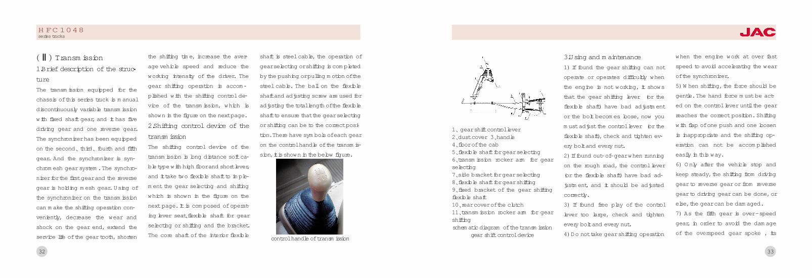
2.Shifting control device of thetransmissionThe shifting control device of thetransmission is long distance soft ca鄄ble type with high floor and short lever,and it take two flexible shaft to imple鄄ment the gear selecting and shiftingwhich is shown in the figure on thenext page. It is composed of operat鄄ing lever seat尧flexible shaft for gearselecting or shifting and the bracket.The core shaft of the interior flexible
shaft is steel cable, the operation ofgear selecting or shifting is completedby the pushing or pulling motion of thesteel cable. The ball on the flexibleshaft and adjusting screw are used foradjusting the total length of the flexibleshaft to ensure that the gear selectingor shifting can be to the correct posi鄄tion. There have symbols of each gearon the control handle of the transmis鄄sion, it is shown in the below figure.
32
control handle of transmission
HFC1048series trucks
33
3.Using and maintenance1) If found the gear shifting can notoperate or operates difficultly whenthe engine is not working, it showsthat the gear shifting lever (or theflexible shaft) have bad adjustmentor the bolt becomes loose, now youmust adjust the control lever (or theflexible shaft), check and tighten ev鄄ery bolt and every nut.2) If found out-of-gear when runningon the rough road, the control lever(or the flexible shaft) have bad ad鄄justment, and it should be adjustedcorrectly.3) If found free play of the controllever too large, check and tightenevery bolt and every nut.4) Do not take gear shifting operation
when the engine work at over fastspeed to avoid accelerating the wearof the synchronizer.5) When shifting, the force should begentle. The hand force must be act鄄ed on the control lever until the gearreaches the correct position. Shiftingwith flap of one push and one loosenis inappropriate and the shifting op鄄eration can not be accomplishedeasily in this way.6) Only after the vehicle stop andkeep steady, the shifting from drivinggear to reverse gear or from reversegear to driving gear can be done, orelse, the gear can be damaged.7) As the fifth gear is over -speedgear, in order to avoid the damageof the overspeed gear spoke , its
1尧 gear shift control lever2尧dust cover 3尧handle4尧floor of the cab5尧flexible shaft for gear selecting6尧transmission rocker arm for gearselecting7尧side bracket for gear selecting8尧flexible shaft for gear shifting9尧fixed bracket of the gear shiftingflexible shaft10尧rear cover of the clutch11尧transmission rocker arm for gearshiftingschematic diagram of the transmission
gear shift control device

34
running speed is under 50 km/h, thefifth gear can be used .8) When running, if find there is ab鄄normal noise in the transmission,stop the vehicle and check it, elimi鄄nate the malfunction.9) When sliding on the downgrade,stalling of the engine is unallowed,starting the engine with the inertia ofsliding on the downgrade is forbid鄄den to avoid the damage of the gearand the synchronizer.10) In the running -in period of thenew vehicle, because the metalchipping which was produced by thefrictional function between new partsis bad to components in the trans鄄mission, especially to the life of theconical ring on the synchronizer, so
the lubricating oil should be replacedafter the running -in period of thenew vehicle expires. Under generalcondition, for every 6000 km running,replace the lubricating oil once.When replacing the lubricating oil,first drain the oil in the transmission,prop up the rear axle, shift the trans鄄mission into the reverse gear, addthe kerosene, rotate the transmissionfor 2耀3 minutes, then drain the kero-sene, add the pure gear oil.11冤 Check the oil level in the trans鄄mission frequently, if found the levelis under the lower edge surface ofthe oil filler bolt hole, sufficient oilshould be added.12冤 Check the outside bolt of thetransmission and the flange of the
second shaft for tightness and theoperating state of the component inthe transmission frequently, becausethe vent plug is blocked by dust andpressure in the transmission increas鄄es, the oil seepage or leakage maybe found, so the vent plug should becleaned periodically.13冤 The movement parts of shiftingoperation should be kept good lubri鄄cating, or else, the shifting operationmay become difficult because of thewear of the movement parts. If foundthe position of gear selecting is in鄄correct, or gear shifting become dif鄄ficult or the transmission is out ofgear automatically in using, firstlyyou should readjust the gear select鄄ing and gear shifting mechanism.
HFC1048series trucks
35
(芋) Drive shaft1.General structureThe two-piece driveshaft, connectedwith transmission on the front endand with rear axle on the back end.
2.Use & Inspection1冤Driveshaft has been counterpoisedin factory, it should be ensured not tobe impacted in use and not to beknocked and stacked in disassembleand carry. Replace if the shaft is dis鄄torted or the balancer is desquamat鄄ed, otherwise there will be vibration,noise, and extra impact in travel, itcan damage power train and endan鄄ger driver.2冤Regularly check the cross shaftneedle bearing, check the sealing of
the slide spline and replace the oilseal when necessary3冤The first maintenance ,to fill greaseto universal joint ,slide spline ,oil pis鄄tol ,driving spindle and quickly tightthe blot in order to sliding the univer鄄sal joint .According to moment ratioto checking and tighten driving spin鄄dle and the middle parts of bearingblots.The second maintenance ,to check鄄ing is there anything fall down aboutthe dirt proof boot ; is there anyproblems about move the universaljoint .when cross shaft in the middleof the needle bearing .The distancewould not be very large .If it is toolarge ,you would be disassemble theuniversal joint and you can depend
on what you need to changing nee鄄dle bearing universal joint.When you do the third maintenance ,should be disassemble the drivingspindle .Pay attention to sign onflange ,cross shaft ,link fork, slidespline in order to mounting .Whenyou finished all the maintenances ,please do the blance check , thestandard of dyramic blance is 2750r/min.The amount of unbalance ismore than 144g.cm遥渊IV冤 Rear axleThe brief of structure 院Single reduc鄄tion rear axle ,as the final part ofpower train of truck ,is the drivingaxle ,and it is composed of finaldrive and differential and axle hous鄄ing .Final drive can not only change

36
the direction of driving force ,but alsoreduce the rotate speed .It is com鄄posed of drive pinion and drivengear and final drive .The drive pinionis composed with drive shaft ,whoseend with spline is connected with uni鄄versal joint assembly by couplingflange .Center support is mounted intwo opposite conical bearing ,so thatit can suffer not only radical bearing ,but also axial force. Drive pinion,whose small-end journal mounted indirect tapered roller bearing, can on鄄ly support radial force. It is fixed onthe flange which located on top leftof differential case by several bolts.A differential, composed of differen鄄tial case and cross and four side pin鄄ions, let the left wheel rotate at a dif鄄
ferent speed from the right wheel.Rear one -piece banjo style axlehousing is made by means of weld鄄ing punched armor plate.Meshing of tooth face and clearanceadjustment of final drive(1) Check drive pinion bearing forpretension .The pretightening force ofdrive pinion bearing should be ad鄄justed. Measuring in the bolt hole ofdrive pinion bearing case, the tan鄄gential pull should be 15~30N.(2)The pretightening force of drivepinion bearing can be adjusted bymeans of adding and reducing ad鄄justing shim. Add shim can decreasefriction torque, while reducing shimcan increase it. There are three kindof shim according to thickness
(0.40mm, 0.45mm, 0.5mm).(3) Check final drive for meshing be鄄tween drive pinion and driven gear.The contact area and side play be鄄tween drive pinion and driven gearcan be adjusted by means of adjust鄄ing shim and adjusting collar of dif鄄ferential bearing. There are threekind of shim is 0.30mm and 0.4mm0.45mm, and the 0.5mm Normally,the clearance between these twogears is 0.15~0.25mm, while the sideplay ranges under 0.07mm. To adjustside play, measure four points withequal angle around the driven gear,and the gauge outfit of micrometershould be in a vertical position. Toadjust tooth contact area, driven gearshould be coated with red lead at
HFC1048series trucks
37
three points, and 2 ~3 teeth shouldcoated at every point. Then rotategears clockwise and anti -clockwiseto get the trace of contact area (seethe right figure).The teeth area is not suit the figure(a)which should be adjust it .If thetrace is slanting to the convex orconcave then adding the shims ;ifthe trace is slanting to the convex orconcave ,then reducing the shims.Normal trace should be near thesmall end ,as figure (a):Add shim iftrace near the convex or concavetooth root ,as figure (b)曰Reduce shimif trace near convex or concave toothtop , as figure (c).Adjust the wheel hub bearing of rearaxle: to locking bearing and nut ,then
release1 辕 3要1 辕 4circle遥 Tighten theforce moment to 490要588N.m
Use & maintenance1冤Lubricate for hyperbola bevel gearis very strict, can be only specifiedgear oil. Don't use or mix with othergear oil, or will result in quickenedscratch and wear.2冤Don't remove or adjust the gears
and bearings of final drive, for theyhave been matched and adjusted infactory. Do these only when gearworn and free play is beyond thelimit value, or when bearing axialclearance is beyond the limit, orwhen some of parts damaged.3冤Clean the vent plug regularly,make sure that ventilation is expe鄄dite. A jammed air drain can bringhigher air pressure in rear axle, andit will result in lubricant leak from thedrive pinion seal and other weldingline.4冤Check the lubricant level in axlehousing regularly. Check the lubri鄄cant for quality regularly, and replaceif the chroma and viscosity is abnor鄄mal.

5冤Finished the third maintenance,disassemble the back cover .Thenclean cavity and main reducer axle .To tight the fore moment nut andblot.
渊V冤FrameThe brief of structure :This kind oftruck's chassis is across structureUse & Maintenance :Using longitudi鄄nal beam and cross beam is to fixedthe frame .Using weld and screwthread to connecting .So ,keep all theparts well to exerting the advantageof the frame .When doing the thirdmaintenance checking , if the screwsare lax that should be tight it. If thecross beam have something wrong ,should be mend it .The reason of damage the frame is
overweight , parking position androad and so on. .So ,must followingthe request to driving .
渊遇冤Suspension setGeneral Structure: The suspension ofthis series of trucks is composed ofmultiply variable leaf spring 尧bidirec鄄tional hydraulic telescopic shock ab鄄sorber and transverse stabilizer. Rearleaf spring is composed of mainspring and secondary spring, itsstiffness changes little by little, sothat vehicle is more comfortable forride.
38
1. Front leaf spring 2. Front U bolt3. bumper 4. Front shackle5. Upper bracket of front suspension6. Front absorber 7.nut
front suspension assembly
1尧Frame 2尧Rear leaf spring3尧Rear center bolt 4尧Rear absorber5尧Secondary spring bracket6尧Rear shackle clamp
rear suspension assembly
HFC1048series trucks
39
2. Use & Maintain leaf spring1)At the beginning of running-in pe鄄riod, check the nut on U -type fas鄄tening bolt and tighten it with speci鄄fied torque when trochometer pointsto 200km and 500km.2)After running-in period, tighten thenut on U -type fastening bolt withspecified torque (with vehicle fullyloaded). Do it also when leaf springis replaced or reset.3)Tighten the nut on U-type fasten鄄ing bolt with specified torque (withvehicle fully loaded) every 2000 ~3000km.4) The first maintenance袁Check andtighten bolts and nuts in your touchon suspension. Check the rubberparts on the suspension and replace
if too much wear.5冤At the second maintenance, doingthe first maintenance items .Thendisassemble and lubricant the springof plate , at the same time to check鄄ing anti-roll stabilizer .6冤At the third maintenance, doingthe second maintenance items . Thendisassemble all of the rubber tochanging the news.7)Take notice of the orientation whenreplace leaf spring or operate on thecenter bolt. Tighten each nut first,then tighten nuts on front U -typefastening bolt with specified torquebefore tighten the rear ones.
3. Use & Check absorber1冤 Check the absorber for tempera鄄ture after running a length on bad
road surface (commonly more than10km). Absorber don't have resis鄄tance if the temperature lower thancondition temperature; if one ab鄄sorber have much lower temperaturethan the symmetrical one, the lowerone's resistance is much moresmaller. Lower resistance result fromlack in oil or from damage of someimportant part, and the absorber thatlack in resistance should be removedto inspect.2冤 Check the absorber for oil leak ifcontinuous abnormal vibration is de鄄tected. Oil leak should be dealt withon time, so that the absorber canwork normally.3冤 Check absorber when maintainingvehicle. To check absorber, stick up

40
it and hold its lower end by vise,then pull and press it for severaltimes. Normally the resistance isbigger when pulled, otherwise theabsorber is damaged or lack in oil.In the case , to changing and mend鄄ing the parts ,then fill oil into shockabsorber .In order to absorber parts.4冤 Always replace the oil seal whenyou replace absorber rod. Don't dis鄄assemble parts such as valve if un鄄necessary.5冤At the third maintenance ,disas鄄semble the shock absorber andchanging the new oil .Do not cleanthe shock absorber.
渊喻冤Front axle1. General structureFront axle assembly is composed of
front axle, steering knuckle, steeringknuckle king pin, hub and tie rod.See the next figure.The front axle is I -beam. The toe鄄ing-in is 3~6mm (diagonal tire) and1~3mm (radial tire). Proper orienta鄄tion can make sure the vehicle stableand easy to control, so that canlessen driver's fatigue and slower tirewear.
2. Adjustment1) Adjustment of front hub bearing.To adjust front hub bearing in axialretightening force, tighten fasteningnut with wrench, and loosen knucklenut for about 120o. Rotate the hubclockwise and anti-clockwise, makesure that roller against the taperedface of bearing outer race properly,then tighten nut to the position wherethe rabbet aims the split pin hole.Check the hub if it can rotate freelyand don't swing a lot. Now, distortthe split pin and fix it.2) Adjustment of clearance betweenknuckle and front axle. The clearanceis adjusted via adjusting shim, itshould less than 0.1mm.3) Adjustment of toeing-in. The toe鄄
1尧Front hub 2尧Brake drum3尧Steering knuckle 4尧King pin5尧Pitman arm 6尧Front axle7尧Tie rod
front axle assembly
HFC1048series trucks
41
ing-in can be adjusted via adjustingtie rod. Park the vehicle on a flatground, jack up its header and orientfront wheels just as vehicle run for鄄ward. Loosen locking nuts of tie rod,rotate the tie rod utile the toeing-in fitthe specified size.
Use & Maintenance1) The first maintenance .When doingthe first maintenance ,check the nuttightly.2) When doing the second mainte鄄nance to checking damage aboutsteering knuckle , steering knucklearm ;to checking about steeringknuckle pin bearing ;to checkingabout the drag rod .According to theregulate ,disassembly wheel hub andfill grease with it.
3) when doing the third maintenance,to disassembly the front axle thencleaning and checking it.a) If the distance between steeringknuckle and front axle is very large ,should put a thrust shim on it to ad鄄justing .The distance is 0.1mm to begood.b) When the steering knuckle pinand the bush's distance is 0.15mm,then to change new ones.The dam鄄age distance of the steering knucklepin is to 0.07mm,changing new ones.c) The damage of steering drag rodball end and ball end is too big ,thenchange the new ones.d) When find out the damage of oilseal of the wheel hub , then changethe new ones .
渊峪冤Steering systemGeneral Structure院The steering sys鄄tem of this series of truck is powersteering system.
Power steeringThe steering system composed ofsteering control mechanism, linkagemechanism 尧whole power steeringgear尧power steering pump andpipeline.The energy source of the steeringsystem is depended on driver'sphysical strength and power of en鄄gine .In some emergent cases aboutsteering system that the driver cancontrol the direction .To comparewith some common machine steeringsystem , the power steering systemis very sensitive and secure.

42
Operation Inspection for SteeringMechanism1) Put front wheels on a swivel table.2) Rotate steering wheel clockwiseand anti -clockwise to its limit posi鄄tion, to detect if it is fluent.3) Let engine run in idle speed andcheck steering wheel for free play.The limit value of this free play is 15~35mm. Rotate the adjusting screwclockwise to decrease the free play,while rotate anti -clockwise to in鄄crease.4) When engine run in idle speed,the torque of steering wheel shouldbe around 19.6N.5)When staring the engine to turningsteering wheel to two sides for sever鄄al times .When removing the air from
the engine ,then fill oil into it.6冤Turing the steering wheel to thefront.7冤Turn off the engine to checking oil.If it need oil, then fill it.Note:To checking is steering oil on ahigh temperature .If it has some trou鄄bles, then doing the 4 and 5 stepsagain or mending power steeringpump.
Use and Maintenace1冤 Check the new truck to driving for3000要4000km ,then fill oil to steeringand cleaning oil net.2冤 Always checking the oil measureor oil quantity in the oil crock, if it hassomething wrong that change it .3冤 Do not disassemble the steeringsystem for another side .Pay atten鄄
tion to the oil pump pipeline ,it cannot fill with air in it .keep cleaning it.Step:a) Turn the steering out oil pump intothe steering in oil pump.b) The return oil inlet connect with oil鄄can inlet.4冤 In some troubles of power steer鄄ing, the drive can use the handsteering but could not use for a long鄄time.5冤 Don't steer when parking, since itwill shorten useful life of parts.6冤 According to the regulate to fillhydraulic pressure oil, the environ鄄ment temperature is above 0 益 ,change steering system shouldadopt L -HM 464# wear resistancehydraulic pressure oil; the environ鄄
HFC1048series trucks
43
ment temperature on 0 益 . (the dif鄄ferent number oil can't mix an us鄄age).The import power steering orsteering pump to choose to press oilwith the DEXRONII model numberliquid.(American G.M. standard)
The use and maintenance ofpower steering1)How to use of power steeringa) Don't steer when parking for 5minutes.b) Forbid to steer the steering wheelwhen can not moved.c) Forbid to steer the steering wheelin the same place.d) Forbid to steer the steering wheelspeed for 90turn/m.
2)How to maintenance of powersteering
The main idea is to prevent ,to checkfor scheduled time .Following aboutthe ministry of communications stan鄄dard about the car JT 辕 T201要95叶Thearts and crafts maintenance of car曳and city build ministry standardCJl7要86 叶The technique conditionmending way of the city bus曳.a)Daily maintenance: to checking thetruck when driving in order to yoursecurity.b)One class maintenance(2000-3000kms)i. Each lubrication partto fill thegrease, the power steering should befill the oil on time.ii. Insure cross shaft , cross/lax pullrodten ball end to moved vivid andnot loose.
iii. Check tight each conjunction part.iv. Check pipe conjunction part, in鄄sured and don't leak oil .c)Second class maintenance(10000-15000 kms)i. Chang the power steering oil.ii. Clean and check the steeringwheel.iii. Clean the power steering oil net.Iv Check front axle, ball axle, steer鄄ing knuckle, steering knuckle arm,steering knuckle frname.v. Disassemble, length pull rod,cleaning and checking parts in orderto insure them well.vi.The other parts, please read thereference. (JT 辕 T 201要95 )d)To install steering knuckle plumb鄄ing arm and locate blots. The daily
44
maintenance:i. Insure the location. Find out steer鄄ing knuckle plumbing arm is fall, thenput them on.ii. If the steering knuckle plumbingarm have some mistake, change thenew ones.iii. Tight the steering gear and frame,frame and frame blot.iv. When turning the direction, insurethe length pull rob and steeringknuckle plumbing arm do not inter鄄vene for each other.
渊IX冤Braking systemBraking systems of trucks of this se鄄ries are: parking brake system(centerdrum) and running brake system (airbrake, hydraulic brake)
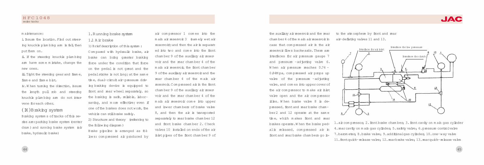
1. Running brake system1.1 Air brake1) Brief description of this system:Compared with hydraulic brake, airbrake can bring greater brakingforce under the condition that forceon the pedal is not great and thepedal stroke is not long; at the sametime, dual-circuit air-pressure driv鄄ing braking device is equipped tofront and rear wheel separately, sothe braking is safe, reliable, labor -saving, and more effective; even ifone of the brakes does not work, thevehicle can still brake safely.2) Structure and theory (referring tothe following diagram)Brake pipeline is arranged as fol鄄lows: compressed air produced by
air compressor 1 comes into themain air reservoir 3 (namely wet airreservoir); and then the air is separat鄄ed into two and come into the frontchamber 9 of the auxiliary air reser鄄voir and the rear chamber 4 of themain air reservoir, the front chamber9 of the auxiliary air reservoir and therear chamber 4 of the main airreservoir. Compressed air in the frontchamber 9 of the auxiliary air reser鄄voir and the rear chamber 4 of themain air reservoir come into upperand lower chambers of brake valve8, and then the air is transportedseparately to rear brake chamber 12and front brake chamber 2. Checkvalves 10 installed on ends of the airinlet pipes of the front chamber 9 of
HFC1048series trucks
45
the auxiliary air reservoir and the rearchamber 4 of the main air reservoir incase that compressed air in the airreservoir flows backwards. There areinterfaces for air pressure gauge 7and pressure -adjusting valve 6.When air pressure reaches 0.74 -0.84Mpa, compressed air props upvalve of the pressure -adjustingvalve, and comes into upper cover ofthe air compressor to make air inletvalve open and the air compressoridles. When brake valve 8 is de鄄pressed, front and rear brake cham鄄ber 2 and 12 operate at the sametime, which makes front and rearbrakes operate. When the brake ped鄄al is released, compressed air infront and rear brake chambers go in鄄
to the atmosphere by front and rearair-deflating valves 11 and 13.
1. air compressor曰 2. front brake chamber曰 3. front cavity on main gas cylinder4. rear cavity on main gas cylinder曰 5. safety valve曰 6. pressure control valve7. barometer曰 8. brake valve曰 9. additional gas cylinder曰 10. one-way valve11. front quick-release valve曰 12. rear brake valve曰 13. rear quick-release valve
Interface for air inletInterface for low pressure
Interface for clutch

46
Brake assemblyThe function of brake is to utilizepower produced by friction betweenbrake drum and brake shoe slice toabsorb kinetic energy of vehicle todecelerate or stop the vehicle. Frontand rear brakes of this brake systemadopt imbalanced structure and aremainly composed of brake chamber,brake arm and brake
HFC1048series trucks
1. return spring locating pin曰 2. roller shaft-brake shoe3. roller-brake shoe曰 4. gripping ring-brake shoe rollershaft曰 5/18. front brake shoe with liner assembly曰6/19. front brake friction plate曰 7. brake cam曰 8. front brake baseboard with liner assembly曰 9. front brake dust cap曰
10. hex bolt曰 11. front brake air chamber support frame with liner assembly曰 12. front left brake air chamber assembly曰13. hex bolt曰 14. front brake adjusting arm assembly曰 15. shoe shaft fixed bolt曰 16. front brake shoe-shoe shaft曰17. front and rear brake shoe shaft-liner曰 18. return spring
47
Adjusting arm1冤Lubrication: mount oil month onadjusting arm, use lithium basegrease periodically to lubricate ad鄄justing arm (maximum lubrication in鄄terval is limited to 10000km), or else,life of adjusting arm will decrease.2冤Check adjusting arm's counter鄄clockwise force moment periodically:rotate adjusting nut of adjusting armcounterclockwise when running every20000km and measure whether therotary moment is bigger than 18Nm,measure for three times repeatedly. Ifthe moment is smaller than 18Nm, itindicates adjusting arm has beendamage and needs to be replacedthe adjusting arm assembly.
BrakeFront brake has the same structurewith the rear brake. It is shoe brakewith camshaft with fixed sustainer.When braking, front and rear shoeslices of the brake press to the rotat鄄ing brake drum by the action of thesame push force; so the rear brakeshoe is called power-reducing brakeshoe. All above lead to imbalance offorces that front and rear brakeshoes press on the brake drum, sothis kind of brake is called simpleimbalanced brake.Clearance between friction disc of thebrake shoe and the brake drum mustbe proper, before adjusting the clear鄄ance, make the front wheel off ground;adjusting steps are as follows:
Full adjustment1. Loosening fixed nut of brake shoebearing pin and nut of binding bolton cam bracket.2. Rotate brake shoe bearing pin soas to make clearance between frontshoe and bearing pin end the sameas that between rear shoe and bear鄄ing pin.3. Start braking, make brake shoefriction disc lean against brake drumclosely and brake camshaft auto鄄matic positioned and tighten nut ofbinding bolt on support frame.4. Release braking and rotate wormso as to make brake shoe frictiondisc lean against brake drum closely.Then counter -rotate worm, releasedby 3/4r, brake drum should be rotate

48
freely.5. Test drive after adjustment, checkworking condition of brake, whetherthe brake drum get hot and whetherbraking distance is proper. If not,readjust it
Parts checkingTo move the worm of brake arm toadjusting the distance betweenbrake assembly and brake drum .The way院 to the worm for clockwiseand move it again and again when itcan moved.Then move the worm forcouter -clockwise to 1 辕 2要3 辕 4circle.At last the drake drum work agility .The distance between brake frictionpiece and brake drum is 0.25c要0.4mm袁camshaft is 0.45mm.
Brake valveBrake valve is to adjust and controlthe whole brake system.Use and maintenance1)Take care of ita) Should check the tube pressurebefore driving, be air pressure mea鄄sure is 0.6 MPa square can drive,while driving in normally is in the O.74 - 0.84 MPas,should park the carwhether leak air or not and whetherthe compressor normal work or not.b)When driving the truck to checkbrake system. If it has somethingwrong should be change it for an鄄other one.c)The damage of the brake shoeplate is too big, then changing an鄄other one. The piece should be the
same new ones and do not havedirty oil, shatter, chap.d)To change the friction and installshoe plate and brake cam again inorder to adjusting the friction pieceand the brake cam.2)Shedule time maintenance:a) The first maintenance (1500-2000kms)i. To excluding the oil from the gascylinder.ii. To fill with grease where need it.iii. To checking and adjusting thetighten about air compressor .b) The second maintenance(10000要12000km)i. Disassemble and adjust the brakeand adjust the distance betweenbrake shoe friction piece.
HFC1048series trucks
ii Check the air compressor andclean the dust of air valve.iii. Check the brake involucra whichneeds news to changing it.c) The third maintenance (24000要30000km)i. Check and adjust the brake valve .When it need new one then change itii. Check the brake valve pipe .When it need new one then change itiii. Clean all the pipe in order to keepit liquidity.
1.2 Hydraulic brake system
1) General StructureThe running brake system is hy鄄draulic. It is composed of vacuum
booster, vacuum cylinder, mastercylinder, control mechanism, braketube, front brake and rear brake. It issensitive and reliable, and it is sim鄄ple to manipulate. See the last figure.If you feel braking power is not suffi鄄cient when brake pedal is depressedcompletely and oil level is normal,there may be air in brake system.Bleed system in follow sequence.Firstly, bleed RR brake; secondly,bleed LR brake; thirdly, bleed RFbrake; then bleed LF brake. Followthese steps:a. Clean air -drain screw of maincylinder and wheel cylinder;b. Remove oil -drain plug of maincylinder or reservoir and fill it withbrake fluid until fluid level reach the
1尧Control mechanism2尧Vacuum booster3尧Master Cylinder 4尧Reservoir5尧Vacuum cylinder 6尧Brake tube7尧Front & Rear brake
the picture of running brake
connect to enginevacuum pump
49
edge.c. Depress the brake pedal severaltimes before hold it depressed andrelease the air-drain screw to bleed.Repeat doing this until air in tube bebled completely. Keep a little oil left,or air can reenter the system.d. Fill reservoir with brake fluid.
2) Note When Use Brake Fluid淤 The specified brake fluid of thisseries truck is synthetic brake fluid ofclass JG3 (GB10830).于 Never use mixed brake fluid.盂 Synthetic brake fluid is good atsopping up. They should be storagein a clean sealed dry container, keepaway from water, organic solvent,petroleum, and dust. Otherwise thevehicle's capability of brake wouldbe cut down seriously.榆 Clean system with alcohol beforereplacing brake fluid with differentbrand. Follow these if alcohol is un鄄available.a. After drain all old brake fluid, fillreservoir with new fluid near to theopening and bleed system again, in
50
HFC1048series trucks
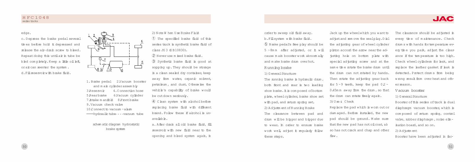
schematic diagram hydrostaticbrake system
1. Brake pedal 2.Vacuum boosterand main cylinder assembly
3.Reservoir 4. Connection hose5.Rear brake 6.Vacuum cylinder7.Intake manifold 8.Front brake9. Vacuum check valve10.Connect to vacuum-alarm要要要hydraulic tube vacuum tube
order to sweep old fluid away.b. Fill system with brake fluid.虞 Brake pedal's free play should be5 ~8mm after adjusted, or it willcause main booster work abnormallyand make brake drum over hot.
Running brake1) General StructureThe running brake is hydraulic drum,both front and rear is two leadingshoe brake. It is composed of bottomplate, wheel cylinder, brake shoe setwith pad, and return spring set.2) Adjustment of Running BrakeThe clearance between pad anddrum will be bigger and bigger dueto wear. In order to ensure brakework well, adjust it regularly followthese steps.
Jack up the wheel which you want toadjust and remove the seal plug. Dialthe adjusting gear of wheel cylinderpiston accord the arrow near the ad鄄justing hole on bottom plate withspecial adjusting screw and at thesame time rotate the brake drum untilthe drum can not rotated by hands.Then rotate the adjusting gear backfor 5 ~9 teeth, keep the pad 0.2 ~0.45mm away from the drum, so thatthe drum can rotate freely again.3) Use & CheckReplace the pad which is worn out ordamaged. Before installed, the newpad should be ground. Make surethat the new pad has not oil coat, al鄄so has not crack and chap and otherflaw.
The clearance should be adjusted inevery time of maintenance. Checkdrums with hands for temperature ev鄄ery time you park, adjust the clear鄄ance if the temperature is too high.Check wheel cylinders for leak, andreplace the leather gasket if leak isdetected. Protect drums from beingwrong result from over heat and oth鄄er reason.
Vacuum booster1) General StructureBooster of this series of truck is dualdiaphragm vacuum booster, which iscomposed of return spring, controlvalve, rubber diaphragm, noise elim鄄ination board, and so on.2) AdjustmentBooster have been adjusted in fac鄄
51
tory, don't disassemble it and protectthe diaphragm from been damaged.
1.3 Parking brake system
parking brake systemcontrol mechanism
The parking brake system includescontrol lever, pull wire, and parkingbrake, as the last figure. Parkingbrake, which is mounted next totransmission, is center drum brake. Itcan act on drive shaft when vehicle
is parking. Also it can operate withrunning brake together in emer -gence.2) AdjustmentNormally, the clearance betweenparking brake drum and brake padis 0.65mm, and it is homogeneous inupper and lower parts. The padshould be replaced often. Followthese steps.a. Jacking up rear axle until onewheel deviate from ground.b. Release the brake handle com -pletely, shift gears to neutral position.c. Rotate brake drum until the holegets its lowest position. Insert ascrewdriver through this hole to stirthe adjusting nut upward until brakedrum braked completely
Then return the adjusting nut for 2~6teeth. See the right figure.
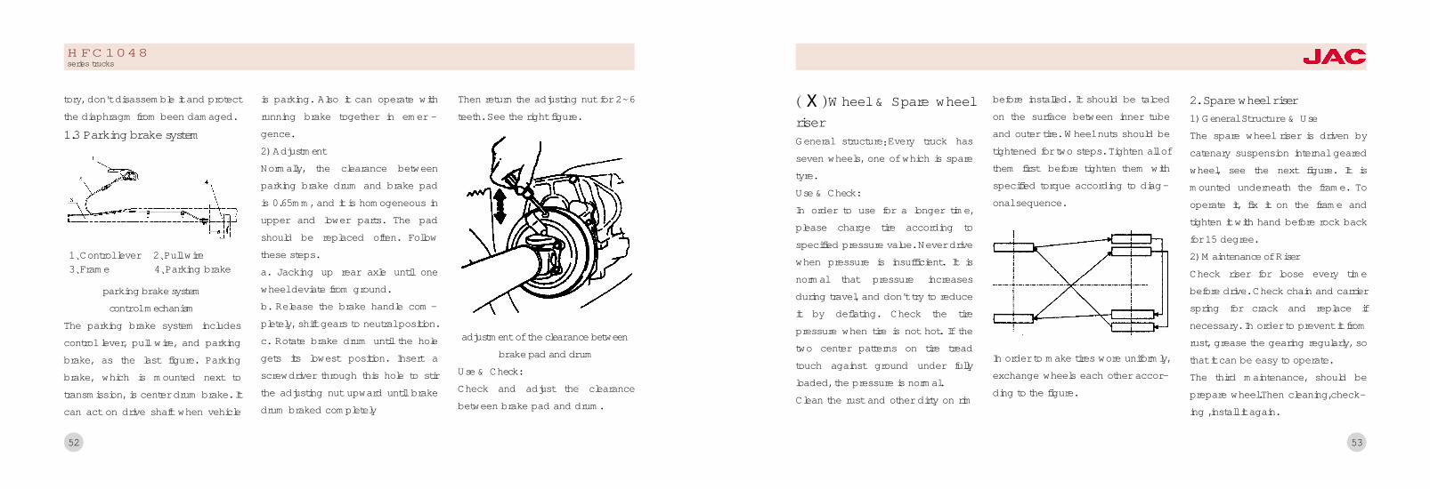
adjustment of the clearance betweenbrake pad and drum
Use & Check:Check and adjust the clearancebetween brake pad and drum.
1尧Control lever 2尧Pull wire3尧Frame 4尧Parking brake
52
HFC1048series trucks
渊愈 冤Wheel & Spare wheelriserGeneral structure院Every truck hasseven wheels, one of which is sparetyre.Use & Check:In order to use for a longer time,please charge tire according tospecified pressure value. Never drivewhen pressure is insufficient. It isnormal that pressure increasesduring travel, and don't try to reduceit by deflating. Check the tirepressure when tire is not hot. If thetwo center patterns on tire treadtouch against ground under fullyloaded, the pressure is normal.Clean the rust and other dirty on rim
before installed. It should be talcedon the surface between inner tubeand outer tire. Wheel nuts should betightened for two steps. Tighten all ofthem first before tighten them withspecified torque according to diag-onal sequence.
In order to make tires wore uniformly,exchange wheels each other accor-ding to the figure.
2. Spare wheel riser1) General Structure & UseThe spare wheel riser is driven bycatenary suspension internal gearedwheel, see the next figure. It ismounted underneath the frame. Tooperate it, fix it on the frame andtighten it with hand before rock backfor 15 degree.2) Maintenance of RiserCheck riser for loose every timebefore drive. Check chain and carrierspring for crack and replace ifnecessary. In order to prevent it fromrust, grease the gearing regularly, sothat it can be easy to operate.The third maintenance, should beprepare wheel.Then cleaning,check-ing ,install it again.
53

1尧Frame 2尧Spare wheel riser as鄄sembly 3尧Eccentric wheel4尧Spare wheel 5尧Chain 6尧Carrier
spare wheel riser set
54
HFC1048series trucks
55
IV尧Electrical equipment(玉) Starter
(域) Generator and adjuster
(芋) Illumination equipments
(郁) Battery
(吁) Sensor

57
Use the measuring cell to testing.Put the car and the measuring cell
for a line, from measuring cell screento testing left, right, the far and nearlight beam to project light upon di鄄rections to be partial to move a valuerespectively.To adjusting the headlight' the up鄄rightess and the level. To adjustingthe passing beam , make it match di鄄agram the shining area center re鄄
quest a left and right light to left andright (the V is left-the V is left, the Vis right-the V is right for the middlepoint) be partial to move a value tobe no bigger than a 100 mms.
2. Small lightTwo small lights are embedded onthe two symmetrical corner of frontpanel. They should be turned on
Right ScreenLeft
Left Right
10 m
headlamp(old series)
(玉)StarterNote:1) Starter should be connected withbattery correctly.2) Every time start, don't keep starterwork continuously for more than 15sand stop for 1-2 seconds in the in鄄terval, since over hot may damage it.Rest it before try start once again.3) After several continuative failures,check starter, solenoid switch, bat鄄tery, wires, and also oil supply sys鄄tem. Retry after trouble is shot.
(域)Generator and adjusterNote:
1) Generator should be connectedwith adjuster correctly, and the po鄄larities of generator and adjuster
should be matched properly.2) Never check generator by short-circuit fire wire and magnetic field.3冤The diode and insulation of gener鄄ator can be inspected with multime鄄ter and ohmmeter. Don't usemegohmmeter to inspect, also ACpower whose voltage exceeds 200v.
(芋) Illuminate equipments1. HeadlampThis series of truck have two head鄄lamps which are embedded in frontof cab symmetrically. The headlampwhich is called double filament bulbhas two different pieces of filamentand can shine two different kinds ofray, the brighter one is used as highlamp while the dimmer one is usedas low lamp. Running in night, turn
on the high lamp to lighten the road,but switch to low lamp when two ve鄄hicles pass each other.In order to see the road clearly ,when you stripping and re-assemblyheadlight that you sould be adjuste鄄ment the position . The way is to putthe car on a evenly road then put ascreen in front of the car. The dis鄄tance between the car and thescreen is about 10meters.(as picture)
56
headlamp(new series)
HFC1048series trucks
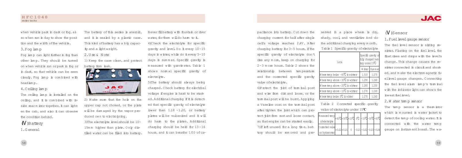
59
pacitance into battery. Cut down thecharging current for half after singlecell's voltage reaches 2.4V. Aftercharging battery for 3~5 hours, if thespecific gravity of electrolyte don'trise any more, keep on charging for2~3 more hours. Table 2 shows therelationship between temperatureand the corrected specific gravityvalue of electrolyte.6)Protect the joint of terminal postand wire from dirt and loose, or theterminal post will be burnt. Applyinga Vaseline coat on the terminal postafter tighten the joint which can pro鄄tect joint from rust and loose contact,so that engine can be started easily.7)If left unused for a long time, bat鄄tery should be removed and pre鄄
served in a place where is dry,shady, cool, and ventilative And dothe additional charging every month.
(吁)Sensor1. Fuel level gauge sensorThe fuel level sensor is sliding re鄄sister. Floating on the fuel level, thefloat rises and drops with the level'schange. This change causes the re鄄sister connected in circuit and short鄄ed, and make the electromagnetic fu鄄el level gauge changes. Connectingthe fuel level alarm lamp's terminalwith the indicator light can shows thelowest fuel level.
2. Water temp sensorThe temp sensor is a thermistorwhich is mounted in water jacket todetect the temp of cooling water. It isconnected with the water tempgauge on instrument board. The wa鄄
Loca
Specific gravity offully charged bat鄄tery under 15益
Where temp above -30益 in winter 1.290 1援260Where temp above -20益 in winter 1援280 1援250Where temp above -10益 in winter 1援270 1援240Where temp below 0益 in winter 1援270 1援240
Winter SummerWhere temp below -40益 in winter 1援310 1援270
Table 1 Specific gravity of electrolyte
Measured tempof electrolyte
+45益+30益+15益 0益 -15益-30益-45益
Corrected valueon hydrometer
+0.02 +0.01 0 -0.01 -0.02 -0.03 -0.04
Table 2 Corrected specific gravityvalue of electrolyte under 15益
when vehicle park in dark or fog, al鄄so when run in day to show the posi鄄tion and the width of the vehicle.
3. Fog lampFog lamp can light further in fog thanother lamp. They should be turnedon when vehicle run or park in fog orin dark, so that vehicle can be seenclearly. Fog lamp is combined withheadlamp.
4. Ceiling lampThe ceiling lamp is installed on theceiling, and it is combined with in鄄side rear mirror together. It can light鄄en the cab, and also it can observethe condition behind.
(郁)Battery1. General
The battery of this series is aneroid,and it is sealed by a plastic case.This kind of battery has a big capac鄄ity and a light weight.
2. Use & Note1) Keep the case clean, and protectbattery from leak.
2) Make sure that the hole on theupper cap not choked, or the platewill be damaged by the vapor pro鄄duced own to electrolyzing.3)The electrolyte level should be 10~15mm higher than plate. Only dis鄄tilled water can be filled into battery.
Never fill battery with fountain or riverwater, for them will do harm to it.4)Check the electrolyte for specificgravity and level. Do it every 10~15days in winter, while do it every 5~10days in summer. Specific gravity ismeasured with gravimeter. Table 1shows normal specific gravity ofelectrolyte.5)The battery should always beingcharged. Check battery for electricalvoltage if engine is hard to be start鄄ed. Additional charging if it is detect鄄ed that specific gravity of electrolytelower than 1.18 ~1.20, or batteryplates will be vulcanized and it willdo harm to the plates. Additionalcharging should be held for 13 ~16hours, and it can breathe 1/10 of ca鄄
58
HFC1048series trucks

61
吁尧Vehicle service and maintenance(玉) Notice during running-in period
(域) Daily maintenance
(芋) Second-class maintenance
(郁) Seasonal maintenance
ter temp sensor has a negative tem鄄perature coefficient and its resistancedecreases with the increase of watertemperature. Don't replace the sen鄄sor with a positive temperature coef鄄ficient one, or the water temp gaugecan not work correctly.
3. Oil pressure alarmOil pressure alarm is a normal closedswitch. It will be opened when oilpressure reaches and over the low鄄est pressure, so that circuit is dis鄄connected and indicator goes out.
60
HFC1048series trucks
63
well. Don't drive in high speed whenthe temp is below the normal temp(between 80oC and 90oC).5) Regularly check the engine cylin-der cover, wheel nuts, car body, andthe U-bolt of leaf spring for tighten.Check the steering system, brakesystem, and clutch for normal oper-ation. Check steering wheel for freeplay. Check the brake pedal andclutch pedal for operating stroke andfree play.Note: Cylinder cover bolts should betightened twice when the cylinder iscool,according to diagonal sequencefrom the center to sides.6) The oil should be replaced after500km尧1000km尧 2500km (do it whenengine is hot), then it will be repl -
aced again in second -class main -tenance.
3. After running-in period1) Replace engine oil and oil filtercore. Replace oil in transmissioncase and rear axle, and replacelubrication in steering gear, also hubbearing grease.2) Check all external bolts and nutswith specified torque.3) Apply grease on all points whereshould be lubricated.4) Do items of first -class mainten -ance.
渊域冤Daily maintenameWhen you find out some mistakesabout the trucks, you must checkand resolve it at the first time. It isvery important to do periodical
service for the truck. As a result ofthe area and periodical service aredifferent, so you should be take careof the truck to periodical service.The following references is how totake good care of the chassis. Doesnot introduce about the seasonservice.User can follow the basisabout area to do season service.Everyday routine maintenanceEveryday you do not use the truck ,you may check about it, in order tohaving a good technology.1.To checking the engine and fill withrust prevention and antifreeze oolant.In winter,let out water from theengine.If you want to using antifreezecoolant that you must follow the airtemperature.
渊I冤 Notice during running -in periodTo improve vehicle's reliability andeconomical efficiency and also to useit longer, follow these during running-in period which is specified as about2500km.1. Before running-in period1) Wa sh vehicle with water, andcheck all bolts and nuts for tighten.2) Check the radiator for enoughwater,and check the engine,transmi-ssion, rear axle, and steering gearbox for enough lubrication,also checkbattery and reservoir for liquid level.3冤check brake system尧drive system,and steering system for correctoperation.4) Check electrical equipments and
lamp instruments for correctoperation, and check brake systemfor normal air pressure.5) Check the shift gears for right; thecontrol parts for normality, transm -ission for shifting smoothly, and theindicator should works correctly.6) Check tires for proper air pres -sure.7) Check that if driver tools andaccessories are taken.
2. During the running-in period1) The new truck should run onsmooth road, and don't make it loadmore than 50% of its rated loadbefore it traveled 800km and don'tload more than 75% before 1500km,or it will shorten truck's life and bringdriver danger.
1)Put so many goods in the trucks ,itwill be curtail the car's life and alsoinfluence your safety.2) Don't run faster than the followspeed.First gear 7km/hSecond gear 14km/hThird gear 26km/hForth gear 40km/hFifth gear 56km/h3) At the beginning, check the rearaxle, transmission case, driveshaft,and brake drum for temperature.Give ear to the sound of chassiswhen driving and stop to inspect ifabnormal noise is heard, then shoottrouble before drive again.4) Both the cooling water temp andoil pressure should be noticed very
62
HFC1048series trucks

64
2.To checking the measure lubricantoil of the engine.3.To checking the degree of tensionand measure of injury about the fanbelt.4.To checking brake system when itwas working or sealing the atmosph-eric pressure (hydraulic pressure)and pipe line.5.To checking the work aboutdirection system circumstance,whether each bolt and the nut hasn'tloosen to move.The cotter pin is verytight.6.To checking weather the springabout armor plate7.To checking the atmospheric pres-sure of wheel.To finding where isharmful position about the wheel and
nut.8.Notice to fill water to the airreservoir everyday.
(芋 )Second-class mainte-nanceWhen the ne w car was driving forone period which should take dailycare and scheduled care.In order tounderstanding the basis usage andthe technology.The car drive on acommon road,the second mainten -ance mileage is 15000 kilometers.The car is going to do the secondmaintenance,you can come to JACSpecial Repair Shop and we will tryour best to help you.
渊郁冤Seasonal maintenanceIn order to keep some parts meet therequirements of climate on aspects
of technique and work request, doseasonal maintenance.At the beginning of summer:1. Cleanout water scale in the coolantsystem.2. Replace lubrication for summer.3. Fueling with #0 diesel oil specifiedin GB252.4. Clean up the battery and adjustthe specific gravity of electrolyte.At the beginning of winter:1. Clean up the battery and adjustthe specific gravity of electrolyte.Then remove and charge it.2. Install cold proofing devices, alsokid preventation devices if neces鄄sary.3. Fueling with #10 diesel oil speci鄄fied in GB252.
HFC1048series trucks
65
遇尧Trouble shooting1援Electrical parts trouble shooting
2尧Clutch trouble shooting
3援Drive shaft trouble shooting
4尧Transmission trouble shooting
5尧Front axle trouble shooting
6尧Rear axle trouble shooting
7尧Steering mechanism trouble shooting
8尧Running brake trouble shooting
9尧Parking brake failure shooting
10 尧Suspension set trouble shooting
11尧Wheel trouble shooting

67
Trouble symptom and probable cause Checking and remedy
(1)Not start(a)Incorrect connection(b)Barry output Incorrect connection(c)Lubricant is not the standard.(d)Start the relay is incorrect.
(d) Clean the battery(b) Clean and tight it(c) replace lubricant(d) repair and replace
(2)Insufficient electric capacity(a) New battery without circulation of charge and dis鄄
charge, or not been charged to rated quantity.(b) Generator without charge or enough charge.(c) Damaged pole plate.(d) Low level or improper specific gravity of electrolyte
(a)Charge as specified
(b)Check connections and repair(c) Check and repair(d)Fill up electrolyte and charge battery with it separatedfrom vehicle
1援Electrical parts trouble shooting
66
Being used, the vehicle will often bebroke along with it travels longer andlonger. In order to recover vehicle tonormal proper situation, also to pro鄄long its life, the trouble must beenfind out and then been disposed inan effective way.* To shoot troubles of engine, seeEngine Operating Instruction Manualwhich every vehicle have been e鄄quipped.Checking and remedy of electri鄄cal systemfuel gauge not moveSpread fuel-gauge and take it iron, ifthe fuel -gauge needle point towardfuel-gauge have already break downor the instrument fuse was burn out,should check to fix or replace. If the
fuel-gauge still motionless, it meansthe fuel-gauge to break down.The hydraulic indicator isn't bright:Dismantle hydraulic -pneumatic alertmachine bottom, and take it iron. Ifthe hydraulic-pneumatic indicator isbright at this time, the elucidation ishydraulic -pneumatic to report themachine switch damage, should re鄄place. If still not bright, explain theindex sign lamp bulb burn bad,should replace, perhaps is launchthe engine oil road contain break鄄down.Dynamo is not workDynamo is work well, but indicatorlight is not work.The main cause oflamp connection is not well.
HFC1048series trucks

69
2. Clutch trouble shooting
Trouble symptom and probable cause Checking and remedy
(1) Shaking clutcha. Overloading too much vehicleb. Not start in low gearc. Defective release bearing or insufficient oild. Corrugated fin cracked, friction lining worn, loose rivet,
damper spring broken, or damper fin broken down.
a. Load by rated loadb. Start in first gear when loading muchc. Clean, lubricate or replaced. Replace
(2) Clutch Slipa. Thin friction lining, rivet reveal, or oil coatb. Weak pressure of diaphragm springc. Too short free play of pedald. Vehicle loads too muche. Not start in low gearf. The pedal is hold pressed when running
a. Clean, or rivet a new friction liningb. Replacec. Adjust to 3~5mmd. Load accord the rated loade. Start in low gearf. Change your bad driving habit
68
Trouble symptom and probable cause Checking and remedy
渊3冤Too much waste of electrolyte(a) High charging amperage. Elactrolyte vaporize or ov-
erflow(b) Leak battery
渊a冤Reduce the frequency of starting and shorten the start鄄ing time .Decrease amperage of charging current渊b冤Replace cover of the battery.
渊4冤Self-discharge of battery渊a冤Battery output cable short to ground渊b冤A short circuit between pole plates渊c冤Damaged or breakdown cell divider渊d冤Dire external surface of battery case .Metal impurities
mixed into electrolyte
渊a冤Clean the output cable ,dispose the short渊b冤Check and repair渊c冤Check and repair(d) Clean the battery case .Tighten shield .Replace elec鄄trolyte if necessary
HFC1048series trucks

70
Trouble symptom and probable cause Checking and remedy
(3) Clutch can't release completelya. Too long free play of pedalb. Wear or crack locking collarc. Crack or distort of wave sheetd. Broken damper spring
a. Adjust to 3~5mmb. Replacec. Replaced. Replace
(4) Gears hard to mesha. High speed idle speed of engineb. Improper meshing of clutchc. Coherence of clutch plated. Bend clutch slip sleeve
a. Adjust the idle speedb. Adjust clutchc. Repair or replaced. Replace
HFC1048series trucks
71
Trouble symptom and probable cause Checking and remedy
(1) Noise or vibration of driveshafta. Worn universal joint
b. Bending of drive shaftc. Loose couple flange or center bracket boltsd. Defective center bracket rubber sleevee. Insufficient lubrication
a. Change spider direction or replace universal joint as鄄semblyb. Align or replacec. Retightend. Replacee. Fill up after cleaning
(2) Overheating center bracketa. Too much tight of oil sealb. Too bigger a inclination between drive shaft and
crankshaftc. Insufficient lubrication
a. It will disappear along with travel longerb. Check and adjust the inclination
c. Fill up regularly
3援Drive shaft trouble shooting

72
Trouble symptom and probable cause Checking and remedy
(1) Gears break off
a. Worn or damaged coupling
b. Loosen nuts or bolts
c. Improperly adjusted linkage
d. Distorted, worn, or crack spring or locking ball
e. Worn shift fork and groove face
f. Worn synchronizer hub and sleeve
g. Worn or damaged synchronizer hub and engagement
sleeve
h. Worn or damaged bearing of input shaft and output
shaft
i. Worn or damaged thrust ring and thrust washer
j. Loosen bolts which mount transmission to engine
a. Replace the coupling
b. Tighten
c. Readjust
d. Repair or replace parts
e. Replace shift fork
f. Replace
g. Replace
h. Replace bearing
i. Replace
j. Tighten
4. Transmission trouble shooting
HFC1048series trucks
73
Trouble symptom and probable cause Checking and remedy
(4) Hard to shifta. Improper adjustment of shift knobb. Worn hinge joint or pinc. Worn control mechanismd. Loosen bolts or nuts
a. Adjust shift knobb. Replacec. Replaced. Check and tighten
(2) Gears hard to mesha. High speed idle speed of engineb. Improper meshing of clutchc. Coherence of clutch plated. Bend clutch slip sleeve
a. Adjust the idle speedb. Adjust clutchc. Repair or replaced. Replace
(3) Noise from transmissiona. Loosen bolts which mount transmission to engineb. Worn gear or bearing
a. Tightenb. Replace
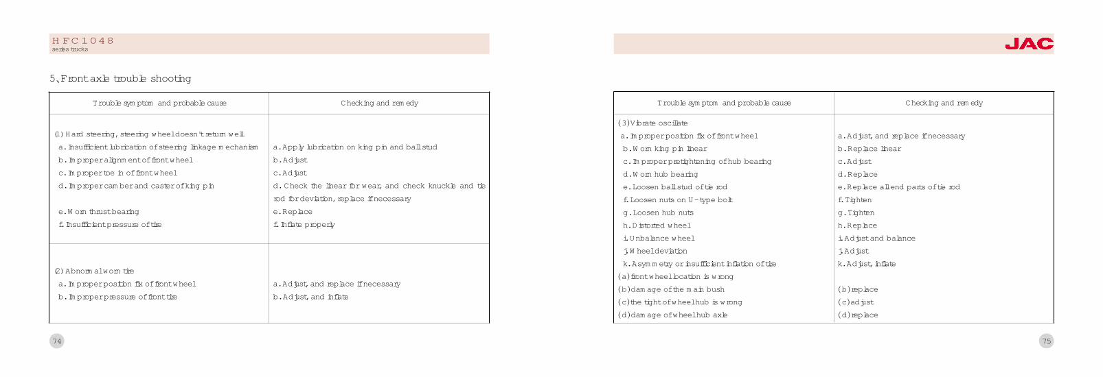
74
Trouble symptom and probable cause Checking and remedy
(1) Hard steering, steering wheel doesn't return wella. Insufficient lubrication of steering linkage mechanismb. Improper alignment of front wheelc. Improper toe in of front wheeld. Improper camber and caster of king pin
e. Worn thrust bearingf. Insufficient pressure of tire
(2) Abnormal worn tirea. Improper position fix of front wheelb. Improper pressure of front tire
a. Apply lubrication on king pin and ball studb. Adjustc. Adjustd. Check the linear for wear, and check knuckle and tierod for deviation, replace if necessarye. Replacef. Inflate properly
a. Adjust, and replace if necessaryb. Adjust, and inflate
5尧Front axle trouble shooting
HFC1048series trucks
75
Trouble symptom and probable cause Checking and remedy
渊3冤Vibrate oscillatea. Improper position fix of front wheelb. Worn king pin linearc. Improper pretightening of hub bearingd. Worn hub bearinge. Loosen ball stud of tie rodf. Loosen nuts on U-type boltg. Loosen hub nutsh. Distorted wheeli. Unbalance wheelj. Wheel deviationk. Asymmetry or insufficient inflation of tire
渊a冤front wheel location is wrong渊b冤damage of the main bush渊c冤the tight of wheel hub is wrong渊d冤damage of wheel hub axle
a. Adjust, and replace if necessaryb. Replace linearc. Adjustd. Replacee. Replace all end parts of tie rodf. Tighteng. Tightenh. Replacei. Adjust and balancej. Adjustk. Adjust, inflate
渊b冤replace渊c冤adjust渊d冤replace
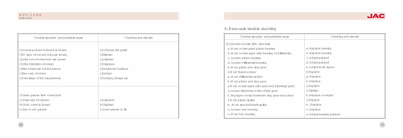
76
Trouble symptom and probable cause Checking and remedy
渊e冤cross pull rod ball end is loosen渊f冤U type of nut and blot are loosen渊g冤the nut of wheel hub are loosen渊h冤the distortion of wheel渊i冤the wheel are not imbalance渊j冤the wap of wheel渊k冤shortage of the air pressure
渊4冤leak grease from wheel hub渊a冤damage of oil seal渊b冤hub cover is loosen渊c冤too much grease
渊e冤change the parts渊f冤tighten渊g冤tighten渊h冤replace渊i冤adjust the balance渊j冤adjust渊k冤adjust袁charge air
渊a冤replace渊b冤tighten渊c冤use grease to fix
HFC1048series trucks
77
Trouble symptom and probable cause Checking and remedy
(1) Abnormal noise from rear axlea. Worn or damaged pinion bearingb. Worn or damaged side bearing of differentialc. Loosen pinion bearingd. Loosen differential bearinge. Worn pinion and ring gearf. Worn thrust washerg. Worn differential spiderh. Worn pinion and ring geari. Worn or damaged side gear and planetary gearj. Loosen tightening bolts of ring geark. Improper contact between ring gear and pinionl. Worn pinion splinem. Worn rear half shaft splinen. Loosen hub bearingo. Worn hub bearing
a. Replace bearingb. Replace bearingc. Adjust preloadd. Adjust preloade. Adjust tooth spacef. Replaceg. Replaceh. Replacei. Replacej. Tightenk. Replace or adjustl. Replacem. Replacen. Replaceo. Adjust bearing preload
6. Rear axle trouble shooting
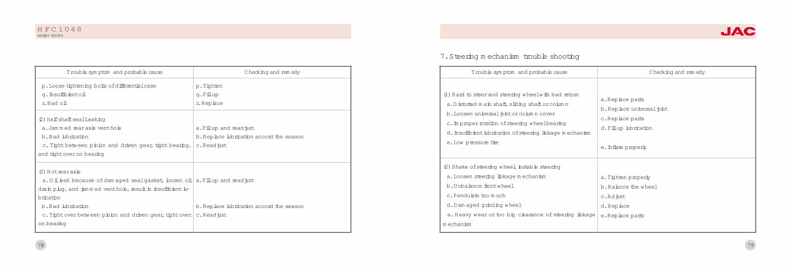
78
Trouble symptom and probable cause Checking and remedy
(3) Hot rear axlea. Oil leak because of damaged seal gasket, loosen oil
drain plug, and jammed vent hole, result in insufficient lu鄄brication
b. Bad lubricationc. Tight over between pinion and driven gear, tight over
on bearing
a. Fill up and readjust
b. Replace lubrication accord the seasonc. Readjust
p. Loose tightening bolts of differential caseq. Insufficient oilr. Bad oil
p. Tightenq. Fill upr. Replace
(2) half shaft seal Leakinga. Jammed rear axle vent holeb. Bad lubricationc. Tight between pinion and driven gear, tight bearing,
and tight over on bearing
a. Fill up and readjustb. Replace lubrication accord the seasonc. Readjust
HFC1048series trucks
79
Trouble symptom and probable cause Checking and remedy
(2) Shake of steering wheel, instable steeringa. Loosen steering linkage mechanismb. Unbalance front wheelc. Pendulate too muchd. Damaged grinding wheele. Heavy wear or too big clearance of steering linkage
mechanism
a. Tighten properlyb. Balance the wheelc. Adjustd. Replacee. Replace parts
(1) Hard to steer and steering wheel with bad returna. Distorted main shaft, sliding shaft or columnb. Loosen universal joint or column coverc. Improper rotation of steering wheel bearingd. Insufficient lubrication of steering linkage mechanisme. Low pressure tire
a. Replace partsb. Replace universal jointc. Replace partsd. Fill up lubrication
e. Inflate properly
7. Steering mechanism trouble shooting
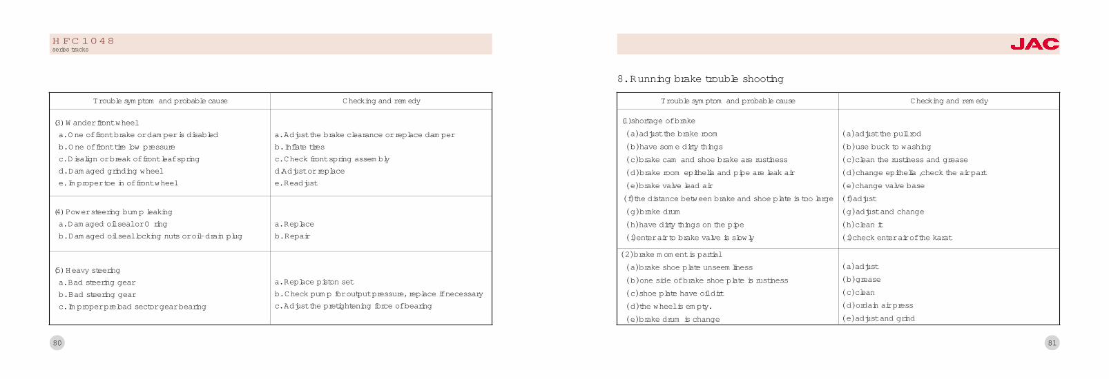
80
Trouble symptom and probable cause Checking and remedy
(5) Heavy steeringa. Bad steering gearb. Bad steering gearc. Improper preload sector gear bearing
a. Replace piston setb. Check pump for output pressure, replace if necessaryc. Adjust the pretightening force of bearing
(3) Wander front wheela. One of front brake or damper is disabledb. One of front tire low pressurec. Disalign or break of front leaf springd. Damaged grinding wheele. Improper toe in of front wheel
a. Adjust the brake clearance or replace damperb. Inflate tiresc. Check front spring assemblyd.Adjust or replacee. Readjust
(4) Power steering bump leakinga. Damaged oil seal or O ringb. Damaged oil seal locking nuts or oil-drain plug
a. Replaceb. Repair
HFC1048series trucks
81
Trouble symptom and probable cause Checking and remedy
渊2冤brake moment is partial渊a冤brake shoe plate unseemliness渊b冤one side of brake shoe plate is rustiness渊c冤shoe plate have oil dirt渊d冤the wheel is empty.渊e冤brake drum is change
渊a冤adjust渊b冤grease渊c冤clean渊d冤ordain air press渊e冤adjust and grind
(1)shortage of brake渊a冤adjust the brake room渊b冤have some dirty things渊c冤brake cam and shoe brake are rustiness渊d冤brake room epithelia and pipe are leak air渊e冤brake valve lead air渊f冤the distance between brake and shoe plate is too large渊g冤brake drum渊h冤have dirty things on the pipe渊i冤enter air to brake valve is slowly
渊a冤adjust the pull rod渊b冤use buck to washing渊c冤clean the rustiness and grease渊d冤change epithelia ,check the air part渊e冤change valve base渊f冤adjust渊g冤adjust and change渊h冤clean it渊i冤check enter air of the karat
8. Running brake trouble shooting

83
Trouble symptom and probable cause Checking and remedy
(3) Bad absorptiona. Insufficient damping fluidb. Having no maintaince regularlyc. Damaged rubber collar
a. Fill up as ratedb. Maintain regularlyc. Replace
(1) Broken leaf springa. Load too much or partial to one wheelb. Frequent emergency brake, drive too fast on uneven
roadc. Loosen U-bolt. Loosen or broken spring clampd. Failed damper
a. Load properly as ratedb. Keep your mind on driving, so that avoid emergencybrake and slower speed on uneven roadc. Tighten U-bolt. Tighten or replace spring clamp.d. Repair or replace
2) Noise in driving Check and replace rubber suspension part
10. Suspension trouble shooting
82
Trouble symptom and probable cause Checking and remedy
a. Big clearance between brake pad and drum
b. Oil coat on brake pad or drumc. Badly worn friction pad
a. Adjust the clearance until both its upper and lower is0.65mmb. Clean with waterc. Replace
9. Parking brake failure shooting
HFC1048series trucks

84
Trouble symptom and probable cause Checking and remedy
(1) Badly worn tirea. High or low tire pressureb. Too much overloading or dissymmetrical loadingc. Loosen wheel hub bearingd. Improper toe-in of front wheel
e. Frequent emergency brake, flare up when starting, oraccelerate suddenly
f. No wheel transposition
a. Inflate by specificationb. Load as ratedc. Adjustd. Adjust the toe-in until it is 3~6mm (for diagonal tire)and 1~3mm (for radial tire)e. Drive stably, don't drive too fast
f. Transposition regularly
11. Wheel trouble shooting
HFC1048series trucks
85
No.
1
Vehicle type
HFC1048Ktype truck
Engine type
YZ4102QFYZ4105QFCY4102BQ
Inside dimensionof the cargo body
(l伊w伊h)渊mm冤
4130伊1960伊400
AxleBase(mm)
3308
2HFC1048KR1
type truck3800伊1960伊400 3308
3HFC1048K1type truck
CY4102BZLQYZ4102ZLQ
4130伊1960伊400 3308
Outside dimension(l伊w伊h)
(mm)
5910伊2096伊2250
5910伊2096伊2250
5910伊2096伊2250
Enginepower
(ml/kW)
3856/70.64087/75
3856/70.6
3856/883432/81
4HFC1048K1R1
type truckCY4102BZLQYZ4102ZLQ
3800伊1960伊400 33085910伊2090伊22503856/883432/81
5HFC1048KDtype truck
CY4102BZLQCY4102BZQ
3856/883856/88
5910伊2096伊2250 4130伊1960伊400 3308
喻尧Automotive model table of trucks
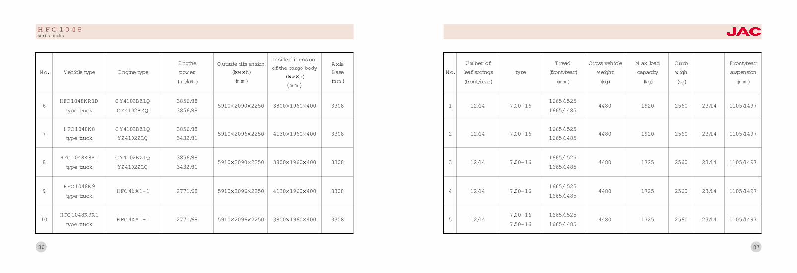
86
No.
6
Vehicle type
HFC1048KR1Dtype truck
Engine type
Inside dimensionof the cargo body
(l伊w伊h)渊mm冤
3800伊1960伊400
AxleBase(mm)
3308
7HFC1048K8type truck
4130伊1960伊400 3308
8HFC1048K8R1
type truckCY4102BZLQYZ4102ZLQ
3800伊1960伊400 3308
Outside dimension(l伊w伊h)
(mm)
5910伊2090伊2250
5910伊2096伊2250
5910伊2090伊2250
Enginepower
(ml/kW)
3856/883432/81
9HFC1048K9type truck
HFC4DA1-1 4130伊1960伊400 33085910伊2096伊22502771/68
10HFC1048K9R1
type truckHFC4DA1-1 2771/68 5910伊2096伊2250 3800伊1960伊400 3308
CY4102BZLQCY4102BZQ
CY4102BZLQYZ4102ZLQ
3856/883856/88
3856/883432/81
HFC1048series trucks
87
No.
1
Umber ofleaf springs(front/rear)
12/14
tyreMax loadcapacity
(kg)
1920
2 12/14 1920
3 12/14 7.00-16 1725
Cross vehicleweight
(kg)
4480
4480
4480
Tread(front/rear)
(mm)
1665/15251665/1485
4 12/14 7.00-16 172544801665/15251665/1485
5 12/147.00-167.50-16
1665/15251665/1485
4480 1725
7.00-16
7.00-16
1665/15251665/1485
1665/15251665/1485
Curbwigh(kg)
2560
2560
2560
2560
2560
Front/rearsuspension
(mm)
23/14 1105/1497
23/14 1105/1497
23/14 1105/1497
23/14 1105/1497
23/14 1105/1497

88
No.
6
Umber ofleaf springs(front/rear)
12/14
tyreMax loadcapacity
(kg)
1725
7 12/14 1725
8 12/14 7.00-16 1725
Cross vehicleweight
(kg)
4480
4480
4480
Tread(front/rear)
(mm)
1665/15251665/1485
9 12/14 7.00-16 179043651665/15251665/1485
10 12/14 7.00-161665/15251665/1485
4365 1785
7.00-167.50-16
7.00-16
1665/15251665/1485
1665/15251665/1485
Curbwigh(kg)
2560
2560
2560
2380
2380
Front/rearsuspension
(mm)
23/14 1105/1497
23/14 1105/1497
23/14 1105/1497
1185/2050
1185/2050
HFC1048series trucks
89
峪尧AppendixMain lubricating position and the lubricant name(for reference)
Description of the oil in lubricating table (for reference)
Main files along with the vehicle

90
No.
1
8
Lubricating position
universal joint of the driveshaft
Filer cartride
Symbol ofthe lubricant
G
Number ofthe ubricating
3
1
2 spline of the driveshaft G 1 fill
3 battery terminal G 2 fill
4 transmission Z 6L渊reference冤 fill
5oil cup of the clutch brake
master cylinderY suitable one change one year
6 steering gear Z 1
7steering knuckle pin and ball pinof the drag link and the tie rod
G 各 2 check
fill
fill
replace
replace replace
replace replace
replace
replace replace
maintenace cycle
everydayFirsttime
Secondetime
Thirdtime
Everyseason
Table one Main lubricating position and the lubricant name(for reference)
HFC1048series trucks
91
No.
9
Lubricating position
generator
Symbol ofthe lubricant
G
Number ofthe ubricating
2 fill
10 Power steering D 1
11 bearing of the front尧rear hub ZL Each 2
12 Shack absorber Q 2
13 Water pump bearing G 1
14Transimission drivegear front bearing
G 1
15 Rear axle Z 1
fill
fill
replace replace
replace
fill
replace
replace
maintenace cycle
everydayFirsttime
Secondetime
Thirdtime
Everyseason
16 Engine lubrication system 1 fill replace replace
17Cooling system
drive mechanismZL 2 fill
fill fill

92
Symbol in thetable
B
D
Lubricant
L-BCD4 oil GB11123渊summer冤袁LECD30 oil GB11123渊winter冤
L-HM46(GB11119), the below zero is L-LM32(GB11119) antiwear hydraulic oil.
J 15W/20 or 15W/40 thickened oil
G GB49 2# lime base grease
ZL GB5671 universal lithium base grease
Q Half HU-20 gasoline engine oil渊GB2537冤and half 45# transformer oil 渊GB2536冤
Y brake fluid JG3渊GB10830冤
Z medium-load vehicle gear oil渊GL-4冤 85W/90
Table two Description of the oil in lubricating table (for reference)
HFC1048series trucks
93
Number
1
2
3
4
5
6
7
Name Tightening torque渊N窑m冤
Nuts of steering tie rod ball pin 186依20渊19依2冤Nuts connected the transmission and the clutch housing 68.8-93.2渊7-9.5冤Intermediate driveshaft flange nuts 343-539渊35-55冤tyer nut 196-245渊20-25冤Diving gear flange nuts 220-250渊23-25.5冤Fixing nuts of the steering straight arm 441依49渊45依5冤U-bolt of the front leaf spring 250
8 U-bolt of the rear leaf spring 350
9 steering fix bolt 68.8-88.2渊7-9冤10 Fixing nuts of steering flexural arm 441依49渊45依5冤11 Steering-wheel fix nut 49-78.4渊5-8冤12 Transmission flange nuts >166.7渊17冤13 Pitman arm shaft nut 196-235.2渊20-24冤
Table three Tightening torque of main fastening pieces (for reference)

94
1尧叶Operating specification of HFC1040 series trucks曳
2尧叶Operating specification of engine曳
3尧Products certification
The nameplate of JAC series trucks is located on the right side of longitudinal member beside front suspension.
Main files along with the vehicle
HFC1048series trucks
95
ANHUI JIANGHUAI AUTOMOBILE CO., LTD.Address院176# Dongliu Road Hefei CityTelephone院0551-2296374Postalcode院230022Network address院http://www.jac.com.cn