j30-09590 high efficiency gas-fired propeller unit heaters
TRANSCRIPT

10/21
NXIM-6J30-09590
Unit No. Serial No.
ATTENTION: READ THIS MANUAL AND ALL LABELS ATTACHED TO THE UNIT CAREFULLY BEFORE ATTEMPTING TO INSTALL, OPERATE OR SERVICE THESE UNITS! CHECK UNIT DATA PLATE FOR TYPE OF GAS AND ELECTRICAL SPECIFICATIONS AND MAKE CERTAIN THAT THESE AGREE WITH THOSE AT THE POINT OF INSTALLATION. RECORD THE UNIT MODEL AND SERIAL No. (s) IN THE SPACE PROVIDED. RETAIN FOR FUTURE REFERENCE.
FOR YOUR SAFETYThe use and storage of gasoline or other flammable vapors and liquids in open containers in the vicinity of this appliance is hazardous.
FOR YOUR SAFETYIf you smell gas:1. Open windows.2. Don't touch electrical switches.3. Extinguish any open flame.4. Immediately contact your gas supplier.
APPROVED FOR USE IN CALIFORNIA
INSTALLER'S RESPONSIBILITYInstaller Please Note: This equipment has been test fired and inspected. It has been shipped free from defects from our factory. However, shipment and installation problems such as loose wires, leaks, or loose fasteners may occur. It is the installer's responsibility to inspect and correct any problem that may be found.
RECEIVING INSTRUCTIONSInspect shipment immediately when received to determine if any damage has occurred to the unit during shipment. After the unit has been uncrated, check for any visible damage to the unit. If any damage is found, the consignee should sign the bill of lading indicating such damage and immediately file claim for damage with the transportation company.
APPROVED FOR USE IN CALIFORNIA
Install, operate, and maintain unit in accordance with the manufacturer's instructions to avoid exposure to fuel substances, or substances from incomplete combustion, which can cause death or serious illness. The state of California has determined that these substances may cause cancer, birth defects, or other reproductive harm.
Improper installation, adjustment, alteration, service, or maintenance can cause property damage, injury, or death. Read the installation, operating, and maintenance instruction thoroughly before installing or servicing this equipment.
INSTALLATION INSTRUCTIONS AND PARTS IDENTIFICATION
HIGH EFFICIENCY GAS-FIRED PROPELLER UNIT HEATERS
260 NORTH ELM ST., WESTFIELD, MA 01085TEL: (413) 564-5540 FAX: (413) 562-5311
www.mestek.com

2
TABLE OF CONTENTSDESCRIPTION .............................................................2GENERAL SAFETY INFORMATION ............................ 3 Installation Codes .......................................................3 Special Precautions ....................................................3SPECIFICATIONS ........................................................4 Performance & Dimensional Data ...........................4-5INSTALLATION ............................................................6 Locating Units .............................................................6 Air for Combustion ......................................................6 Clearances .................................................................6 Suspension of Units.................................................7-8INSTALLATION - GAS PIPING ....................................9 Pipe Sizing..................................................................9 Pipe Installation ........................................................10INSTALLATION - CONDENSATE PIPING ................. 11ELECTRICAL CONNECTIONS ..................................12 Thermostat Wiring and Location ...............................12 Unit Wiring Diagrams...........................................13-16VENTING - GENERAL GUIDELINES ........................ 17 Vent Termination Clearances ....................................18STANDARD COMBUSTION – HORIZONTALLY VENTED (CAT. IV) ......................................................19STANDARD COMBUSTION – VERTICALLY VENTED (CAT. IV) ...............................20
SEPARATED COMBUSTION – TWO PIPE VENTING ............................................21-22SEPARATED COMBUSTION – CONCENTRIC VENTING ...........................................23 Horizontal Sidewall Mounting ..............................23-25 Vertical Roof Mounting .............................................25GAS CONVERSION ..............................................26-27OPERATION ..............................................................28 Explanation of Controls .......................................28-32 Start-Up ....................................................................32 Shut Down ................................................................32GAS INPUT RATE .....................................................33 High Altitude Deration ...............................................33MODBUS CONFIGURATION .....................................33PNEUMATIC TUBING SCHEMATIC .......................... 34UNIT TROUBLESHOOTING GUIDE .....................35-36LED TROUBLESHOOTING GUIDE ........................... 37MAINTENANCE .........................................................38WARRANTY ...............................................................39IDENTIFICATION OF PARTS ................................40-41 Replacement Parts ...................................................41APPENDIX A – MODBUS REGISTERS ................42-43UNIT NUMBER DESCRIPTION .................................44START-UP AND INSPECTION SHEET ...................... 45
NOTICE: It is the equipment owner’s responsibility to provide any scaffolding or other apparatus required to perform emergency service or annual/periodic maintenance to this equipment.
DESCRIPTIONThe High Efficiency Gas-Fired Unit Heaters are factory assembled, power vented, low static pressure type propeller fan unit heaters designed to be suspended within the space to be heated. THESE HEATERS ARE NOT TO BE CONNECTED TO DUCTWORK. These heaters are design certified under ANSI Z83.8 for industrial/commercial use and residential use as a utility heater. The designs are certified by ETL as providing a minimum of 95+% thermal efficiency, and approved for use in California. Do not alter these units in any way. If you have any questions after reading this manual, contact the manufacturer.
The following terms are used throughout this manual, in addition to the ETL requirements to bring attention to the presence of potential hazards, or to important information concerning the product:
Indicates an imminently hazardous situation which, if not avoided, will result in death, serious injury, or substantial property damage.
Indicates an imminently hazard-ous situation which, if not avoided, could result in death, serious injury, or substantial property damage.
Indicates an imminently hazardous situation which, if not avoided, may result in minor injury or property damage.
NOTICE: Used to notify of special instructions on installation, operation, or maintenance which are important to equipment but not related to personal injury.
Figure 1 - High Efficiency Gas-Fired Propeller Unit Heater
See IDENTIFICATION OF PARTS, Figures 26 through 31

3
GENERAL SAFETY INFORMATION
Failure to comply with the general safety information may result in extensive property damage, severe personal injury, or death.
This product must be install be a licensed plumber or gas fitter when installed within the Commonwealth of Massachusetts.
Installation must be made in accordance with local codes, or in absence of local codes, with the latest edition of the ANSI Standard Z223.1 (N.F.P.A. No. 54) National Fuel Gas Code. All of the ANSI and NFPA Standards referred to in these installation instructions are those that were applicable at the time the design of this appliance was certified. The ANSI Standards are available from CSA Information Services, 1-800-463-6727. The NFPA Standards are available from the National Fire Protection Association, Batterymarch Park, Quincy, MA 02269. These unit heaters are designed for use in airplane hangars when installed in accordance with ANSI/NFPA No. 409, and in public garages when installed in accordance with NFPA No. 88A and NFPA No.88B.
If installed in Canada, the installation must conform with local building codes, or in the absence of local building codes, with CSA-B149.1 “Installation Codes for Natural Gas Burning Appliances and Equipment” or CSA-B149.2 “Installation Codes for Propane Gas Burning Appliances and Equipment.” These unit heaters have been designed and certified to comply with CSA 2.6. Also see sections on installation in AIRCRAFT HANGARS and PUBLIC GARAGES.
Do not alter the unit heater in any way or damage to the unit and/or severe personal injury or death may occur!
Disconnect all power and gas supplies before installing or servicing the heater. If the power disconnect is out of sight, lock it in the open position and tag it to prevent unexpected application of power. Failure to do so could result in fatal electric shock, or severe personal injury.
Ensure that all power sources conform to the requirements of the unit heater, or damage to the unit will result!
Follow installation instructions CAREFULLY to avoid creating unsafe conditions. All wiring should be done and checked by a qualified electrician, using copper wire only. All gas connections should be made and leak-tested by a suitably qualified individual, per instructions in this manual. Also follow procedures listed on GAS EQUIPMENT START-UP AND INSPECTION SHEET located in this manual.
Use only the fuel for which the heater is designed (see rating plate). Using LP gas in a heater that requires natural gas, or vice versa, will create risk of gas leaks, carbon monoxide poisoning, and explosion.
Do not attempt to convert the heater for use with a fuel other than the one intended unless using a factory provided conversion kit. Such conversion is dangerous, as it will create the risks previously listed.
Make certain that the power source conforms to the electrical requirements of the heater.
Do not depend upon a thermostat or other switch as sole means of disconnecting power when installing or servicing heater. Always disconnect power at main circuit breaker as described above. Failure to do so could result in fatal electric shock.
Special attention must be given to any grounding information pertaining to this heater. To prevent the risk of electrocution, the heater must be securely and adequately grounded. This should be accomplished by connecting a ground conductor between the service panel and the heater. To ensure a proper ground, the grounding means must be tested by a qualified electrician.
Do not insert fingers or foreign objects into heater or its air moving device. Do not block or tamper with the heater in any manner while in operation, or just after it has been turned off, as some parts may be hot enough to cause injury.
This heater is intended for general heating applications ONLY. It must NOT be used in potentially dangerous locations such as flammable, explosive, chemical-laden, or wet atmospheres.
Do not attach ductwork to this product or use it as a makeup air heater. Such usage voids the warranty and will create unsafe operation.
In cases in which property damage may result from malfunction of the heater, a back-up system or temperature sensitive alarm should be used.
The open end of gas piping systems being purged shall not discharge into areas where there are sources of ignition or into confined spaces UNLESS precautions are taken as follows: (1) by ventilation of the space, (2) control of the purging rate, (3) elimination of all hazardous conditions. All precautions must be taken to perform this operation in a safe manner! The appliance is not to be used by persons (including children) with reduced physical, sensory or mental capabilities, or lack of experience and knowledge, unless they have been given supervision or instruction. Children being supervised should not play with the appliance.
Unless otherwise specified, the following conversions may be used for calculating SI unit measurements:1 foot = 0.305 m 1 inch = 25.4 mm 1 gallon = 3.785 L 1 pound = 0.453 kg1 psig = 6.894 kPa1 cubic foot = 0.028m3
1000 BTU/cu. ft. = 37.5 MJ/m3
1000 BTU per hour = 0.293 kW1 inch water column = 0.249 kPa1 litre/second = CFM x 0.4721 meter/second = FPM ÷ 196.8

4
Figure 2 - Dimensional Drawing – High Efficiency Unit Heater
"F2"(HANGING)
"K"
"D" "F1"(HANGING)
"E"(HANGING)
"W" "U"
4 SUSPENSION POINTS(THREADED RODS)
CONTROL BOXELECTRICAL
"N"COMBUSTIONAIR
CONDENSATEDRAIN
"L"
3" (77 mm)
"J"
"M"
FRONT VIEW
"G"(DISCHARGE
OPENING)
"C"
"B"
OPENING)
"H"(DISCHARGE "A"
CAT-10081D
TOP VIEW
UNIT HEATER100 TO 400 SIZES
REAR VIEW
ELECTRICALCONNECTION
CONNECTIONGAS
FLUE "P"
"Q"
"T"
"R"
"S"
"E"(HANGING)
"F1"(HANGING) "D"
"L"
"F2"(HANGING)
"M" 3" (77mm)
"K"
"J" "U"
"W"
"H"(DISCHARGE
"A""C"
"B"
OPENING)
"G"(DISCHARGE
OPENING)
4 SUSPENSIONPOINTS(THREADED RODS)
ELECTRICALCONTROLBOX
TOP VIEW
50 SIZEUNIT HEATER
REAR VIEW
FRONT VIEW
BOTTOM VIEW
GASCONNECTION
"P"FLUE
ELECTRICALCONNECTION
"Q"
"R"
"T"
"S"
COMBUSTIONAIR "N"
SPECIFICATIONS
CAT-10081D
Size 50 Dimensional Data
Size 100-400 Dimensional Data

5
Table 1 - Performance and Dimensional Data - High Efficiency Unit Heater
Unit Capacity (MBH) 50 100 150 200 300 400PERFORMANCE DATA†Input Maximum - BTU/Hr. 50,000 100,000 150,000 200,000 300,000 400,000
(kW) (14.6) (29.3) (43.9) (58.6) (87.9) (117.2)Input Minimum - BTU/Hr. 16,660 33,330 50,000 66,660 100,000 133,330
(kW) (4.9) (9.8) (14.6) (19.5) (29.3) (39.1)Output - BTU/Hr. 48,600 96,000 143,000 192,000 285,000 384,000
(kW) (14.2) (28.1) (41.8) (56.3) (83.5) (112.5)Thermal Efficiency (%) 97 96 95 96 95 96Free Air Delivery - CFM 790 1,616 2,661 3,232 4,848 6,464
(cu. m/s) (0.373) (0.763) (1.255) (1.525) (2.288) (3.050)Air Temperature Rise - Deg. F 57 55 50 55 55 55
(Deg C.) (31.7) (30.6) (27.8) (30.6) (30.6) (30.6)Condensate Production gph 0.41 0.73 1.06 1.38 1.71 3.0Full Load Amps at 120V 10.8 11.6 17.6 17.6 31.18 31.18Minimum Circuit Amps at 120V 11.5 13.1 19.1 19.1 33.93 33.93Max. Overcurrent Protection at 120V 14.1 19.1 25.1 25.1 44.93 44.93MOTOR DATA: Motor HP (Qty) 1/14 (2) 1/2 1/2 (2) 1/2 (2) 1 (2) 1 (2)
Motor kW 0.05 0.37 0.37 0.37 0.74 0.74Motor Type, ODP SP PSC PSC PSC PSC PSCRPM 1,500 1,500 1,500 1,500 1,625 1,625Amps @ 115V 5.2 6.0 12.0 12.0 22.0 22.0
DIMENSIONAL DATA - inches (mm)"A" Height to Top of Combustion Air Inlet 13-5/8 18-3/4 18-3/4 18-3/4 27-1/8 34-7/8
(346) (476) (476) (476) (689) (886)"B" Jacket Width of Unit 42-13/16 42-13/16 54-13/16 54-13/16 54-13/16 54-13/16
(1087) (1087) (1392) (1392) (1392) (1392)"C" Unit Height 12-1/4 17-1/4 17-1/4 17-1/4 25-11/16 33-7/16
(311) (438) (438) (438) (653) (850)"D" Depth to Rear of Housing 5-3/4 11 10-5/16 11 10-7/8 11-1/2
(147) (279) (261) (279) (277) (292)"E" Hanging Distance Width 28 27-15/16 38 38 41-3/4 41-3/4
(710) (710) (965) (965) (1060) (1060)"F1" Hanging Distance Depth 17-3/8 17-1/4 21-1/8 21-1/4 20 20
(440) (438) (537) (540) (508) (508)"F2" Hanging Distance Depth 17-3/8 17-1/4 21-1/8 21-1/4 26 26
(440) (438) (537) (540) (660) (660)"G" Discharge Opening Width 15 15 26 26 26 26
(381) (381) (660) (660) (660) (660)"H" Discharge Opening Height 10-1/8 15-7/8 15-7/8 15-7/8 24-3/8 32-1/8
(256) (403) (403) (403) (619) (816)"J" Side Panel to Centerline Combustion Air 2-3/4 2-13/16 3-3/4 3-3/4 3-3/4 3-3/4
(70) (71) (95) (95) (95) (95)"K" Front Panel to Centerline Combustion Air 4-1/2 4-1/2 5-5/16 5-5/16 5-5/16 5-5/16
(114) (114) (135) (135) (135) (135)"L" Overall Unit Depth 32-5/8 38 41 42 42 42
(829) (965) (1040) (1067) (1067) (1067)"M" Side Depth 27-7/16 27-7/16 31-1/4 31-1/4 31-1/4 31-1/4
(697) (697) (794) (794) (794) (794)"N" Combustion Air Inlet Connection Dia. 2 2 2 3 4 4
(51) (51) (51) (76) (102) (102)"P" Flue Connection Diameter 2 2 2 3 4 4
(51) (51) (51) (76) (102) (102)"Q" Side Panel to Centerline Gas Connection 2-1/8 2-5/8 2-5/8 2-5/8 2-5/8 2-5/8
(54) (67) (67) (67) (67) (67)"R" Bottom Panel to Centerline Gas Connection 1-1/2 2-1/2 2-1/2 2-1/2 2-1/2 2-1/2
(40) (64) (64) (64) (64) (64)"S" Side Panel to Centerline Flue 5-3/8 5-1/8 6-1/2 6-1/16 5-3/8 5-3/8
(137) (130) (165) (154) (137) (137)"T" Bottom Panel to Centerline Flue 2-1/2 4-5/8 4-5/8 4-5/8 8-1/8 13-1/8
(64) (117) (117) (117) (206) (334)"U" Side to Centerline Condensate Drain Connection 8-1/2 8-1/2 9-1/2 9-1/2 9-1/2 9-1/2
(216) (216) (241) (241) (241) (241)"W" Rear to Centerline Condensate Drain Connection 9-9/16 9-9/16 10-9/16 10-9/16 10-1/8 10-1/8
(243) (243) (268) (268) (257) (257)Combustion Air Inlet Pipe Dia. - in. 2 2 2 3 4 4
(mm) (51) (51) (51) (76) (102) (102)* Flue Pipe Dia - in. 2 2 2 3 4 4
(mm) (51) (51) (51) (76) (102) (102)Gas inlet - in. 1/2 1/2 1/2 1/2 3/4 3/4Approximate Unit Weight - lb 120 180 209 260 323 385
(kg) (54.4) (81.6) (94.80) (117.9) (146.5) (174.6)Approximate Ship Weight - lb 168 228 254 305 388 460
(kg) (76.2) (103.4) (115.2) (138.3) (176.0) (208.6)† Ratings shown are for unit installations at elevations between 0 and 2,000 feet (0 to 610m). For unit installations in U.S.A. above 2,000 feet (610m), the unit input must be field derated 4% for each 1,000 feet (305m) above sea level; refer to local codes, or in absence of local codes, refer to the latest edition of the National Fuel Gas Code, ANSI Standard Z223.1 (NFPA No. 54). For installations in Canada, any reference to deration at altitudes in excess of 2,000 feet (610m) are to be ignored. At altitudes of 2,000 feet to 4,500 feet (610 to 1372m), the unit must be field derated and be so marked in accordance with the ETL certification. See HIGH ALTITUDE DERATION section and Table 12 for deration information. * Field installed PVC fittings provided with unit sizes 200-400 as follows: - Size 200 units come with a 2" to 3" PVC reducer - Size 300 units come with a 2" to 4" PVC reducer - Size 400 units come with a 2" to 4" PVC drain tee fittingReducers/drain tee fittings are to be field installed per Venting instructions.LEGEND: ODP = Open Drip Proof, PSC = Permanent Split Capacitor, SP = Shaded Pole

6
INSTALLATION Do not install unit heaters in
corrosive or flammable atmospheres! Premature failure of, or severe damage to the unit will result!
Avoid locations where extreme drafts can affect burner operation. Unit heaters must not be installed in locations where air for combustion would contain chlorinated, halogenated or acidic vapors. If located in such an environment, premature failure of the unit will occur!
Since the unit is equipped with an automatic gas ignition system, the unit heater must be installed such that the gas ignition control system is not directly exposed to water spray, rain or dripping water.
Maximum altitude for this unit is 14,000 feet (4,267 meters) unless otherwise noted. For altitudes higher than 14,000 feet (4,267 meters), contact your customer service representative.
NOTICE: Location of unit heaters is related directly to the selection of sizes. Basic rules are as follows:
RESIDENTIAL INSTALLATIONS: This unit heater is design certified under ANSI Z83.8 for residential use as a utility heater. A utility heater is defined as: a low-static unit heater for heating of non-living spaces that are attached to, adjacent to, or part of a structure that contains space for family living quarters.
AIRCRAFT HANGARS: Unit Heaters must be installed in aircraft hangars as follows: In aircraft hangars, unit heaters must be at least 10 feet (3.0 m) above the upper surface of wings or engine enclosures of the highest aircraft to be stored in the hangar, and 8 feet (2.4 m) above the floor in shops, offices and other sections of the hangar where aircraft are not stored or housed. Refer to current ANSI/NFPA No. 409, Aircraft Hangars. In Canada, installation is suitable in aircraft hangars when acceptable to the enforcing authorities.
PUBLIC GARAGES: In repair garages, unit heaters must be located at least 8 feet (2.4 m) above the floor. Refer to the latest edition of NFPA 88B, Repair Garages.
PARKING STRUCTURES: In parking structures, unit heaters must be installed so that the burner flames are located a minimum of 18 inches (457 mm) above the floor or protected by a partition not less than 18 inches (457 mm) high. Refer to the latest edition of NFPA 88A, Parking structures.
In Canada, installation must be in accordance to the latest edition of CSA B149 “Installation Codes for Gas Burning Appliances and Equipment.”
AIR DISTRIBUTION: Direct air towards areas of maximum heat loss. When multiple heaters are involved, circulation of air around the perimeter is recommended where heated air flows along exposed walls. Satisfactory results can also
be obtained where multiple heaters are located toward the center of the area with heated air directed toward the outside walls. Be careful to avoid all obstacles and obstructions which could impede the warm air distribution patterns.
NOTICE: Unit heaters should not be installed to maintain low temperatures and/or freeze protection of buildings. A minimum of 45°F (7.2°C) thermostat setting must be maintained. If the ambient temperature drops to below freezing, it may result in damage to heat exchanger and/or components.
AIR FOR COMBUSTION: The unit heater shall be installed in a location in which the facilities for ventilation permit satisfactory combustion of gas, proper venting, and the maintenance of ambient air at safe limits under normal conditions of use. The unit heater shall be located in such a manner as not to interfere with proper circulation of air within the confined space. When buildings are so tight that normal infiltration does not meet air requirements, outside air shall be introduced per Sections 1.3.4.2 and 1.3.4.3 of ANSI Z223.1 for combustion requirements. A permanent opening or openings having a total free area of not less than one square inch per 5,000 BTU/Hr. (1.5 kW) of total input rating of all appliances within the space shall be provided.
NOTICE: Unit Heater sizing should be based on heat loss calculations where the unit heater output equals or exceeds heat loss.
NOTICE: Unit should be installed in an area where the entering air does not exceed 104°F. Temperatures above 104°F will cause the propeller motor to trip on its thermal overload protection, requiring a cool down period before the motor can reset.
CLEARANCES: Each Gas Unit Heater shall be located with respect to building construction and other equipment so as to permit access to the Unit Heater. Clearance between vertical walls and the vertical sides of the Unit Heater shall be no less than 2 inches (51 mm) for size 50 and 6 inches (152 mm) for sizes 100/400. However, to ensure access to the burner and power venter compartments, a minimum of 18 inches (457 mm) is required for the access panel side. A minimum clearance of 2 inches (51 mm) for size 50 and 6 inches (152 mm) for sizes 100/400 must be maintained between the top of the Unit Heater and the ceiling. The bottom of the Unit Heater must be no less than 2 inches (51 mm) for size 50 and 6 inches (152 mm) for sizes 100/400 from any combustible. The distance between rear of unit and vertical wall should be no less than 18 inches (457 mm) for size 50/200 and 36 inches (914mm) for size 300/400 to maintain inlet air flow. The distance between the flue collector and any combustible must be no less than 6 inches (152 mm). Also see AIR FOR COMBUSTION and VENTING sections.
NOTICE: Increasing the clearance distances may be necessary if there is a possibility of distortion or discoloration of adjacent materials.
7
INSTALLATION (continued)
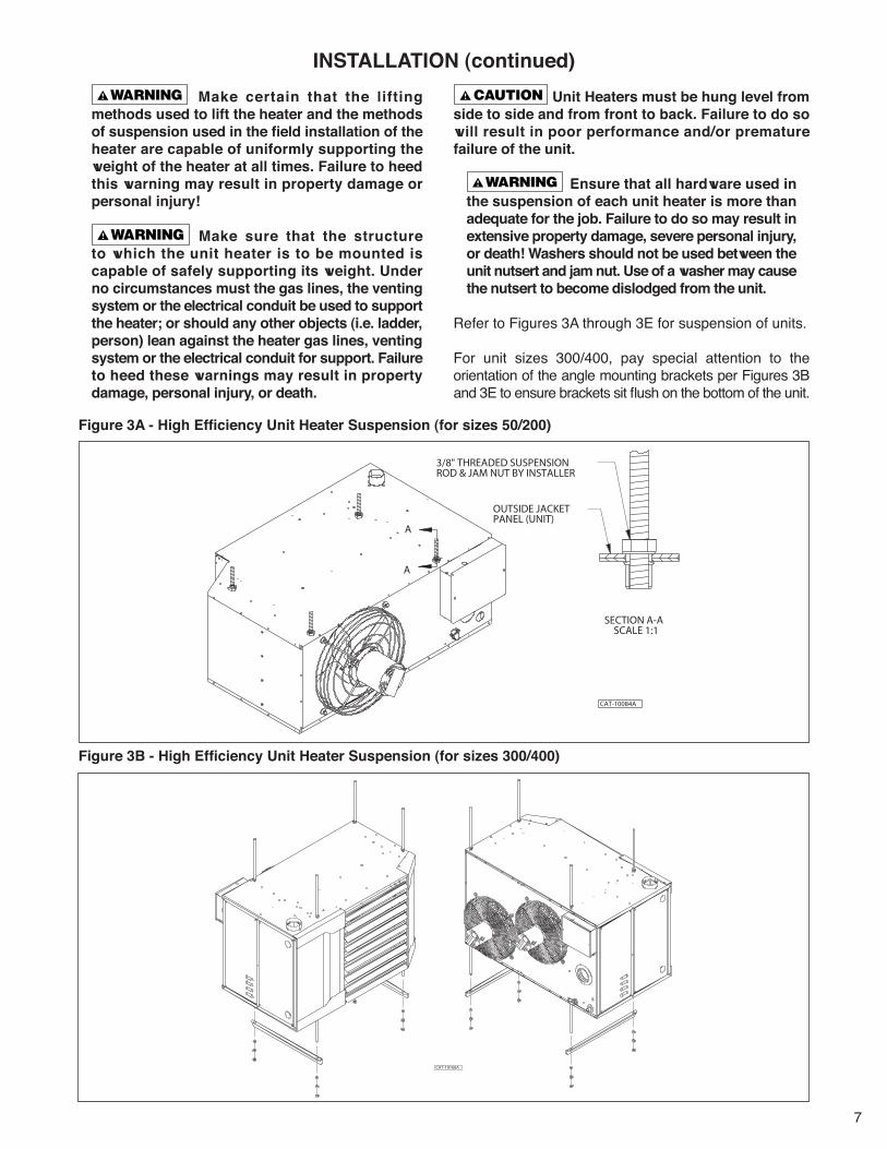
Figure 3A - High Efficiency Unit Heater Suspension (for sizes 50/200)
Figure 3B - High Efficiency Unit Heater Suspension (for sizes 300/400)
CAT-10166A
A
A
CAT-10084A
3/8" THREADED SUSPENSION ROD & JAM NUT BY INSTALLER
OUTSIDE JACKETPANEL (UNIT)
SECTION A-A SCALE 1:1
Make certain that the lifting methods used to lift the heater and the methods of suspension used in the field installation of the heater are capable of uniformly supporting the weight of the heater at all times. Failure to heed this warning may result in property damage or personal injury!
Make sure that the structure to which the unit heater is to be mounted is capable of safely supporting its weight. Under no circumstances must the gas lines, the venting system or the electrical conduit be used to support the heater; or should any other objects (i.e. ladder, person) lean against the heater gas lines, venting system or the electrical conduit for support. Failure to heed these warnings may result in property damage, personal injury, or death.
Unit Heaters must be hung level from side to side and from front to back. Failure to do so will result in poor performance and/or premature failure of the unit.
Ensure that all hardware used in the suspension of each unit heater is more than adequate for the job. Failure to do so may result in extensive property damage, severe personal injury, or death! Washers should not be used between the unit nutsert and jam nut. Use of a washer may cause the nutsert to become dislodged from the unit.
Refer to Figures 3A through 3E for suspension of units.
For unit sizes 300/400, pay special attention to the orientation of the angle mounting brackets per Figures 3B and 3E to ensure brackets sit flush on the bottom of the unit.

8
Figure 3C - Heater Mounting: Steel Construction (for all sizes)
Figure 3D - Heater Mounting: Wood Construction Joists (for sizes 50/200)
Figure 3E - Heater Mounting: Wood Construction Joists (for sizes 300/400)
UNIT HEATER50/200 SIZES
CAT-10065B
THREADEDINSERT
LAG BOLT& WASHER
3/8'' THREADEDROD
2" X 6" LAGBOLTEDACROSS JOISTS
JOIST WASHER& NUT
FRONT OFUNIT HEATER300/400 SIZES
CAT-10165A
LAG BOLT& WASHER
1/2'' THREADEDROD
2" X 6" LAGBOLTEDACROSS JOISTS
JOIST NUT &WASHER
NUT (2)& WASHER
NUT (2)& WASHER
*Note: Angle mounting brackets are provided by the manufacturer for unit sizes 300/400. All other hanging hardware and wood is not included with the unit and should be field supplied.
Table 2 - Max. & Min. Mounting Heights
Unit Size (MBH)
Max HeightFeet(m)
Min HeightFeet(m)
50 13 N/A*(3.96)100 16 8
(4.88) (2.44)150 18 8
(5.49) (2.44)200 24 9
(7.32) (2.74)300 23 9
(7.01) (2.74)400 23 9
(7.01) (2.74)*Minimum clearance to combustibles must be maintained; see CLEARANCES section.

9
200,000 BTU/Hr = 200 Cu. ft./hr. 1,000 BTU/cu. ft. Using Table 3, a 1 inch pipe is needed.
NOTE: See GENERAL SAFETY INFORMATION section for English/Metric unit conversion factors.
NOTICE: If more than one unit heater is to be served by the same piping arrangement, the total cu. ft./hr. input and length of pipe must be considered.
NOTICE: If the gas unit heater is to be fired with LP gas, consult your local LP gas dealer for pipe size information.
NOTICE: HEATER INSTALLATION FOR USE WITH PROPANE (BOTTLED) GAS MUST BE MADE BY A QUALIFIED L.P. GAS DEALER OR INSTALLER. HE/SHE WILL INSURE THAT PROPER JOINT COMPOUNDS ARE USED FOR MAKING PIPE CONNECTIONS; THAT AIR IS PURGED FROM LINES; THAT A THOROUGH TEST IS MADE FOR LEAKS BEFORE OPERATING THE HEATER; AND THAT IT IS PROPERLY CONNECTED TO THE PROPANE GAS SUPPLY SYSTEM.
Before any connection is made to the existing line supplying other gas appliances, contact the local gas company to make sure that the existing line is of adequate size to handle the combined load.
1. Determine the required Cu. Ft./Hr. by dividing the input by 1000. For SI/Metric measurements: Convert BTU/Hr. to kilowatts. Multiply the units inputs (kW) by 0.0965 to determine Cu. Meters./Hr. 2. FOR NATURAL GAS: Select pipe size directly from the table. 3. FOR PROPANE GAS: Multiply the Cu. Ft./Hr. value by 0.633; then, use the table. 4. Refer to the metric conversion factors listed in the General Safety section for SI Unit measurement conversions.
Maximum Capacity of Pipe in Cubic Feet of Gas per Hour (Cubic Meters per Hour) for Gas Pressures of 0.5 psig (3.5 kPa) or Less, and a Pressure Drop of 0.5 Inch Water Column (124.4 Pa) (Based on a 0.60 Specific Gravity Gas) Nominal Iron Internal Length of Pipe, Feet (meters) Pipe Size Dia. 10 20 30 40 50 60 70 80 90 100 125 150 175 200 in. in. (3.0) (6.1) (9.1) (12.2) (15.2) (18.3) (21.3) (24.4) (27.4) (30.5) (38.1) (45.7) (53.3) (61.0) 1/2 0.622 175 120 97 82 73 66 61 57 53 50 44 40 37 35 (4.96) (3.40) (2.75) (2.32) (2.07) (1.87) (1.73) (1.61) (1.50) (1.42) (1.25) (1.13) (1.05) (0.99) 3/4 0.824 360 250 200 170 151 138 125 118 110 103 93 84 77 72 (10.2) (7.08) (5.66) (4.81) (4.28) (3.91) (3.54) (3.34) (3.11) (2.92) (2.63) (2.38) (2.18) (2.04) 1 1.049 680 465 375 320 285 260 240 220 205 195 175 160 145 135 (19.3) (13.2) (10.6) (9.06) (8.07) (7.36) (6.80) (6.23) (5.80) (5.52) (4.96) (4.53) (4.11) (3.82) 1 1/4 1.380 1400 950 770 660 580 530 490 460 430 400 360 325 300 280 (39.6) (26.9) (21.8) (18.7) (16.4) (15.0) (13.9) (13.0) (12.2) (11.3) (10.2) (9.20) (8.50) (7.93) 1 1/2 1.610 2100 1460 1180 990 900 810 750 690 650 620 550 500 460 430 (59.5) (41.3) (33.4) (28.0) (25.5) (22.9) (21.2) (19.5) (18.4) (17.6) (15.6) (14.2) (13.0) (12.2) 2 2.067 3950 2750 2200 1900 1680 1520 1400 1300 1220 1150 1020 950 850 800 (112) (77.9) (62.3) (53.8) (47.6) (43.0) (39.6) (36.8) (34.5) (32.6) (28.9) (26.9) (24.1) (22.7) 2 1/2 2.469 6300 4350 3520 3000 2650 2400 2250 2050 1950 1850 1650 1500 1370 1280 (178) (123) (99.7) (85.0) (75.0) (68.0) (63.7) (58.0) (55.2) (52.4) (46.7) (42.5) (38.8) (36.2) 3 3.068 11000 7700 6250 5300 4750 4300 3900 3700 3450 3250 2950 2650 2450 2280 (311) (218) (177) (150) (135) (122) (110) (105) (97.7) (92.0) (83.5) (75.0) (69.4) (64.6) 4 4.026 23000 15800 12800 10900 9700 8800 8100 7500 7200 6700 6000 5500 5000 4600 (651) (447) (362) (309) (275) (249) (229) (212) (204) (190) (170) (156) (142) (130)
Table 3 - Gas Pipe Size
To avoid damage or possible personal injury, do not connect gas piping to this unit until a supply line pressure/leak test has been completed. Connecting the unit before completing the pressure/leak test may damage the unit gas valve and result in a fire hazard.
Do not rely on a shut-off valve to isolate the unit while conducting gas pressure/leak tests. These valves may not be completely shut off, exposing the gas valve to excessive pressure and damage.
PIPE SIZINGTo provide adequate gas pressure to the gas unit heater, size the gas piping as follows:1. Find the cu. feet/hr. by using the following formula:
Cu. ft./hr. = Input BTU/Hr. 10002. Refer to Table 3. Match “Length of Pipe in Feet” with
appropriate “Gas Input - Cu. Feet/Hr.” figure. This figure can then be matched to the pipe size at the top of the column.
Example: It is determined that a 67 ft. (20.4m) run of gas
pipe is required to connect a 200 MBTU gas unit heater to a 1,000 BTU/cu ft. (0.29kW) natural gas supply.
INSTALLATION – GAS PIPING

10
INSTALLATION – GAS PIPING (continued)NOTICE: Use pipe joint sealant resistant to the action of liquefied petroleum gases regardless of gas conducted.
Check all pipe joints for leakage using a soap solution or other approved method. Never use an open flame or severe personal injury or death may occur!
Figure 4 - Pipe Installation, Standard Controls
Never use an open flame to detect gas leaks. Explosive conditions may exist which may result in personal injury or death!
The appliance and its individual shutoff valve must be disconnected from the gas supply piping system during any pressure testing of that system in excess of 1/2 psig (3.5 kPa).
The appliance must be isolated from the gas supply piping system by closing its individual manual shutoff valve during any pressure testing of the gas supply piping system at test pressures equal to or less than 1/2 psig (3.5 kPa).
PIPE INSTALLATION1. Install the gas piping in accordance with applicable
local codes.2. A field provided lock-up type high pressure regulator
must be used to limit the supply pressure to a maximum of 14 inches W.C. (3.5 kPa). All piping should be sized in accordance with the latest edition of ANSI Standard Z223.1 (NFPA 54), National Fuel Gas Code; in Canada, according to CSA B149. See Table 3 for correct gas piping size. If gas pressure is excessive, install a pressure regulating valve in the line upstream from the main shutoff valve.
NOTICE: For proper operation, unit requires a minimum supply gas pressure of 5 inches W.C. (1.2 kPa) for natural gas or 8 inches W.C. (2.0 kPa) for propane (LP) gas.
3. Adequately support the piping to prevent strain on the gas manifold and controls. Supports should be spaced in accordance with the latest edition of ANSI Standard Z223.1 (NFPA 54), National Fuel Gas Code; in Canada, according to CSA B149.
4. To prevent the mixing of moisture with gas, run the take-off piping from the top, or side, of the main.
5. Gas valve has adjustment ports to adjust flow rate. See START-UP section.
6. Provide a drip leg in the gas piping near the gas unit heater. A ground joint union and a manual gas shutoff valve should be installed ahead of the unit heater controls to permit servicing. The manual shutoff valve must be located external to the jacket (See Figure 4).
7. Make certain that all connections have been adequately doped and tightened.
Do not over tighten the inlet gas piping into the valve. This may cause stresses that will crack the valve!

11
INSTALLATION – CONDENSATE PIPING
The condensate trap provided with the unit must be installed. The condensate trap is designed to provide backpressure for the correct operation of the unit. Do not use a traditional plumbing “P” trap.
NOTICE: The design of the condensate trap assembly provided with the unit has changed. Figure 5A and Table 4 apply to the original trap design; Figure 5B applies to the current trap design. The installation steps below apply to both trap designs.
Figure 5A - Condensate Piping, Original Design
Table 4 - Minimum Condensate Trap Distance (Original Design Only)
Figure 5B - Condensate Piping, Current Design
Sizes 50-100 Size 150-400“X” - Minimum Condensate Trap Distance 2.5" 4.5"
"X"
CONDENSATE CONNECTION
CONDENSATETRAP ASSEMBLY
CAT-10341_ASIZE 50/100 150/400"X" 2.5" 4.5"
1. Remove condensate caution label from condensate connection on bottom of unit.
2. Apply field supplied thread sealant to male threads of condensate trap assembly.
Do not use thread sealing tape in lieu of thread sealant. Parts of the thread sealing tape may break off and prevent the condensate trap from operating properly. This could result in flue gas entering the condensate pipe or nuisance trips.
3. Screw condensate trap assembly into condensate
connection.4. Connect the bottom of the condensate trap assembly to
the rest of the condensate drain system.
NOTICE: Condensate drain system should be pitched away from the unit towards the condensate drain. If not possible due to space requirements, a condensate pump can be used to mechanically assist with condensate drainage. Condensate pipe should be sized based on the total volume of condensate that may flow through it (this includes the total volume of all units if multiple units are connected to a single condensate drain system).
NOTICE: Condensate is acidic; refer to local plumbing and mechanical codes for proper neutralizer and disposal requirements.
5. Check for leaks when unit is operating and producing condensate.
Optional condensate pump, pump-shelf, and condensate neutralizers are available and should be installed per their separate corresponding installation manuals.
5.36 in.
CONDENSATE CONNECTION
CONDENSATETRAP ASSEMBLY
CAT-10437_A

12
HAZARDOUS VOLTAGE! DISCONNECT ALL ELECTRIC POWER INCLUDING REMOTE DISCONNECTS BEFORE SERVICING. Failure to disconnect power before servicing can cause severe personal injury or death.
Standard units are shipped for use on 115 volt, 60 hertz, single phase electric power. The motor name-plate and electrical rating of the transformer should be checked before energizing the unit heater electrical system. All external wiring must conform to the latest edition of ANSI/NFPA No. 70, United States National Electrical Code, and applicable local codes; in Canada, to the Canadian Electrical Code, Part 1, CSA Standard C22.1. The short-circuit current rating (SCCR) for this unit is 5kA.
Field installed step-down transformers provided for units with non-standard supply voltage options 2-7 (any voltage other than 115/1/60) cannot be mounted on the unit due to the weight of the transformer. The step-down transformer should be mounted elsewhere and wired to the unit accordingly. Failure to do so could result in fatal electric shock or severe personal injury.
Do not use any tools (i.e. screwdriver, pliers, etc.) across terminals to check for power. Use a voltmeter.
It is recommended that the electrical power supply to each unit heater be provided by a separate, fused, and permanently live electrical circuit. A disconnect switch of suitable electrical rating should be located as close to the gas valve and controls as possible. Each unit heater must be electrically grounded in accordance with the latest edition of the United States National Electrical Code, ANSI/NFPA No. 70, or CSA Standard C22.1.
THERMOSTAT WIRING AND LOCATION:
NOTICE:The thermostat must be mounted on a vertical, vibration-free surface, free from air currents, and in accordance with the furnished instructions.
Mount the thermostat approximately 5 feet (1.5 m) above the floor, in an area where it will be exposed to a free circulation of average temperature air. Always refer to the thermostat instructions, as well as our unit wiring diagram, and wire accordingly. Avoid mounting the thermostat in the following locations:
ELECTRICAL CONNECTIONS1. Cold Areas - Outside walls or areas where drafts
may affect the operation of the control.2. Hot Areas - Areas where the sun's rays, radiation,
or warm air currents may affect the operation of the control.
3. Dead Areas - Areas where the air cannot circulate freely, such as behind doors or in corners.
Figure 6A - Low-voltage Thermostat Wiring, Single Stage
Figure 6B – Low-voltage Thermostat Wiring, Two Stage
NOTICE: From a cold start, the start-up fan delay should not exceed 30 seconds from after flame sensing.
IMPORTANT: For all wiring connections, refer to the wiring diagram shipped with your unit (either affixed inside the control box access panel or enclosed in the installation instructions envelope). Should any original wire supplied with the heater have to be replaced, it must be replaced with wiring material having a temperature rating of at least 105°C.
Should any high limit wires have to be replaced, they must be replaced with wiring material having a temperature rating of 200°C minimum.
W RR G W1 W2 C
LOW-VOLTAGE
SINGLE STAGE
THERMOSTAT
CAT-10066A
RW1
W1 CR G W2W2
CAT-10122A

13
ELECTRICAL CONNECTIONS (continued)
Figure 7A – Unit Wiring Diagram, High Efficiency Unit Heater Size 50, Equipped with Natural or Propane (LP) Gas, Modulating with Outside Air Reset (Master)

14
ELECTRICAL CONNECTIONS (continued)
Figure 7B – Unit Wiring Diagram, High Efficiency Unit Heater Size 100, Equipped with Natural or Propane (LP) Gas, Modulating with Outside Air Reset (Master)

15
ELECTRICAL CONNECTIONS (continued)
Figure 7C – Unit Wiring Diagram, High Efficiency Unit Heater Size 150/200, Equipped with Natural or Propane (LP) Gas, Modulating with Outside Air Reset (Master)

16
ELECTRICAL CONNECTIONS (continued)
Figure 7D – Unit Wiring Diagram, High Efficiency Unit Heater Size 300/400, Equipped with Natural or Propane (LP) Gas, Modulating with Outside Air Reset (Master)
Figure 7E – Alternate Wiring Diagram Section J8 for Size 150-400 Units Manufactured with Fenwal Ignition Control Board
17
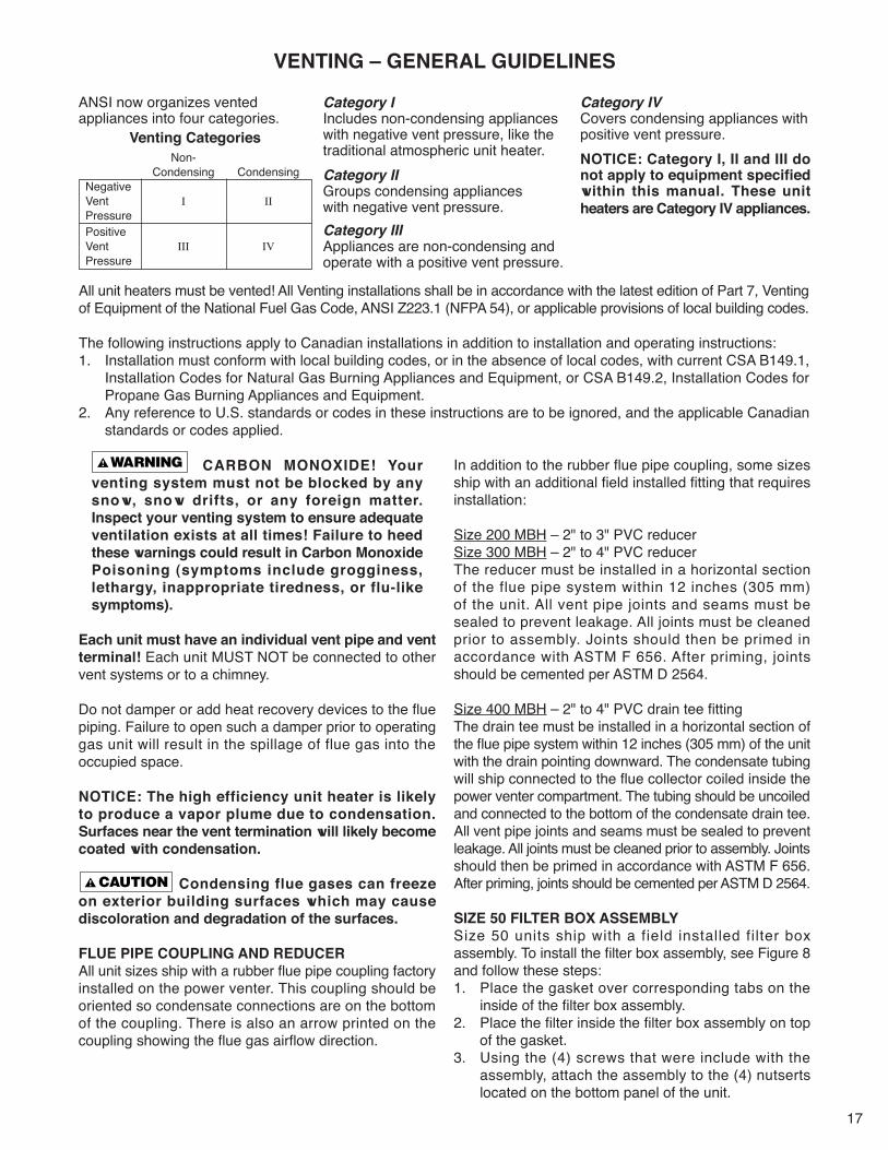
VENTING – GENERAL GUIDELINES
CARBON MONOXIDE! Your venting system must not be blocked by any snow, snow drifts, or any foreign matter. Inspect your venting system to ensure adequate ventilation exists at all times! Failure to heed these warnings could result in Carbon Monoxide Poisoning (symptoms include grogginess, lethargy, inappropriate tiredness, or flu-like symptoms).
Each unit must have an individual vent pipe and vent terminal! Each unit MUST NOT be connected to other vent systems or to a chimney.
Do not damper or add heat recovery devices to the flue piping. Failure to open such a damper prior to operating gas unit will result in the spillage of flue gas into the occupied space.
NOTICE: The high efficiency unit heater is likely to produce a vapor plume due to condensation. Surfaces near the vent termination will likely become coated with condensation.
Condensing flue gases can freeze on exterior building surfaces which may cause discoloration and degradation of the surfaces.
FLUE PIPE COUPLING AND REDUCERAll unit sizes ship with a rubber flue pipe coupling factory installed on the power venter. This coupling should be oriented so condensate connections are on the bottom of the coupling. There is also an arrow printed on the coupling showing the flue gas airflow direction.
ANSI now organizes vented appliances into four categories.
Venting Categories Non- Condensing Condensing Negative Vent I II Pressure Positive Vent III IV Pressure
Category IIncludes non-condensing appliances with negative vent pressure, like the traditional atmospheric unit heater.Category IIGroups condensing appliances with negative vent pressure.Category IIIAppliances are non-condensing and operate with a positive vent pressure.
Category IVCovers condensing appliances with positive vent pressure.NOTICE: Category I, II and III do not apply to equipment specified within this manual. These unit heaters are Category IV appliances.
All unit heaters must be vented! All Venting installations shall be in accordance with the latest edition of Part 7, Venting of Equipment of the National Fuel Gas Code, ANSI Z223.1 (NFPA 54), or applicable provisions of local building codes.
The following instructions apply to Canadian installations in addition to installation and operating instructions:1. Installation must conform with local building codes, or in the absence of local codes, with current CSA B149.1,
Installation Codes for Natural Gas Burning Appliances and Equipment, or CSA B149.2, Installation Codes for Propane Gas Burning Appliances and Equipment.
2. Any reference to U.S. standards or codes in these instructions are to be ignored, and the applicable Canadian standards or codes applied.
In addition to the rubber flue pipe coupling, some sizes ship with an additional field installed fitting that requires installation:
Size 200 MBH – 2" to 3" PVC reducerSize 300 MBH – 2" to 4" PVC reducerThe reducer must be installed in a horizontal section of the flue pipe system within 12 inches (305 mm) of the unit. All vent pipe joints and seams must be sealed to prevent leakage. All joints must be cleaned prior to assembly. Joints should then be primed in accordance with ASTM F 656. After priming, joints should be cemented per ASTM D 2564.
Size 400 MBH – 2" to 4" PVC drain tee fittingThe drain tee must be installed in a horizontal section of the flue pipe system within 12 inches (305 mm) of the unit with the drain pointing downward. The condensate tubing will ship connected to the flue collector coiled inside the power venter compartment. The tubing should be uncoiled and connected to the bottom of the condensate drain tee. All vent pipe joints and seams must be sealed to prevent leakage. All joints must be cleaned prior to assembly. Joints should then be primed in accordance with ASTM F 656. After priming, joints should be cemented per ASTM D 2564.
SIZE 50 FILTER BOX ASSEMBLYSize 50 units ship with a field installed filter box assembly. To install the filter box assembly, see Figure 8 and follow these steps:1. Place the gasket over corresponding tabs on the
inside of the filter box assembly.2. Place the filter inside the filter box assembly on top
of the gasket. 3. Using the (4) screws that were include with the
assembly, attach the assembly to the (4) nutserts located on the bottom panel of the unit.

18
VENTING – GENERAL GUIDELINES
Vent Systems Termination Clearance Requirements
Structure/Object Minimum Clearance for Termination LocationsUSA CANADA
Door, window, or gravity vent inlet; combustion air inlet for other appliances
9 in. for 10,000 to 50,000 BTU/Hr input; 12 in. for input exceeding 50,000 BTU/Hr.
9 in. (230mm) for 10,000 to 50,000 BTU/Hr input; 12 in. (305mm) for input exceeding 50,000 BTU/Hr.
Forced air inlet within 10 ft. 3 ft. above 6 ft. (1.8m)Adjoining Building or parapet 10 ft. 10 ft. (3.04m)
Adjacent public walkways 7 ft. above grade 7 ft. (2.1m) above grade
Electric, gas meters & regulators 4 ft. horizontal 3 ft. (0.9m) horizontally from meter/regulator assembly. 6 ft. (1.8m), any direction, from a gas service regulator vent outlet
Above grade level* 1 ft. 1 ft. (0.3m)*Minimum above maximum snow depth, or per local code, whichever is greater.
Table 5
Figure 8 – Size 50 Filter Box Assembly Installation
FILTER
GASKET
FILTER BOX
CAT-10295A
The filter box must be installed prior to unit operation. Failure to do so may result in damage to the burner assembly.
NOTICE: The filter is only designed to prevent large debris from entering the burner assembly. If there are other contaminants in the space air, the unit should be installed as separated combustion to take outside air into the unit for combustion.

19
This appliance uses a positive pressure venting system. All joints must be sealed completely to prevent leakage of flue products into occupied spaces. Failure to do this may result in severe personal injury, death or major property damage.
1. Horizontal venting arrangements are designed to be used with schedule 40 vent pipe. All heaters should be vented with UL 1738 listed vent pipe. For installations in Canada, use corrosion resistant and gas-tight, listed vent pipe conforming with local building codes, or in the absence of local building codes, with the current CSA-B149.1, Installation Codes for natural Gas Burning Appliances and Equipment or CSA-B149.2, Installation Codes for Propane Gas Burning Appliances and Equipment. Approved vent pipe includes but is not limited to: ULC-S636 PVC or CPVC Vent pipe. Vent pipe must be rated for up to 140°F (60°C) operating temperature. Type B vent should not be used.
Do not use Type B (double wall) vent internally within the building on high efficiency unit heaters! This can result in death, serious injury or substantial property damage.
Use of cellular core pipe for any exhaust vent component is prohibited. Use of cellular core pipe may result in severe personal injury, death, or major property damage.
NOTICE: Installations in Canada require compliance with ULC-S636 Standard for Type BH Gas Venting Systems.
NOTICE: If state or local code do not allow for the use of a PVC vent pipe, flue pipe material must comply with local code requirements.a) If allowed by local code, field provided UL-S636 listed, polypropylene gas vent pipe can be used. See Table 6 for approved supplier/models.b) If metal vent pipe is required by local code, field provided UL 1738 listed, single or double wall vent pipe can be used. See Table 6 for approved supplier/models.
2. The vent pipe diameter MUST be as specified (see Table 1). All unit sizes are factory equipped with the required flue size connector; attach in place (if not already factory-mounted to outlet). See FLUE PIPE COUPLING AND REDUCER section for details.
3. The vent pipe equivalent length must not exceed 50 feet (15.2 m). Equivalent length is total length of straight sections PLUS 5 feet (1.5 m) for each 90 degree elbow and 2.5 feet (0.76 m) for each 45 degree elbow.
4. A minimum horizontal run of 12 inches (305 mm) is required between the unit's flue vent connection and first elbow.
5. The vent terminal must be at least 12 inches (305 mm) from the exterior of the wall that it passes through to prevent degradation of the building material by flue gases. Through the wall vent for these appliances shall NOT terminate over public walkways, or over an area where the condensate or vapor could create a nuisance or hazard or could be detrimental to the operation of regulators, relief valves, or other equipment. See Table 5 for termination clearance requirements.
6. The vent system must be installed to prevent collection of condensate. Pitch horizontal pipes downward 1/4 inch per foot (21 mm/m) toward the unit for condensate drainage.
7. Horizontal portions of the venting systems shall be supported at maximum intervals of 4 feet (1.2 m) to prevent sagging (in Canada, support at 3 feet (1 m) maximum intervals).
8. Seal all vent pipe joints and seams to prevent leakage. All joints must be cleaned prior to assembly. Joints should then be primed in accordance with ASTM F 656. After priming, joints should be cemented per ASTM D 2564.
9. Insulate single wall vent pipe exposed to cold air or running through unheated indoor areas.
10. Each unit must have an individual vent pipe and vent terminal! Each unit MUST NOT be connected to other vent systems or to a chimney. A field provided stainless steel screen may be placed on the end of the flue pipe to prevent animals from entering the venting system.
Figure 9 – Horizontal Venting, Standard Combustion
NOTICE: Increasing the vent termination clearance distances may be necessary if there is a possibility of distortion or discoloration of adjacent materials.
STANDARD COMBUSTION – HORIZONTALLY VENTED UNIT HEATERS (CATEGORY IV)
CAT-10067A
ELBOW OR TEE
EXHAUST
PITCH PIPE DOWN TOWARDSUNIT 1/4" PER FT. (21 mm/m) OFRUN TO ALLOW FORCONDENSATE DRAINAGE
Brand Model
Polypropylene Gas Vent Pipe Duravent PolyproCentrotherm InnoFlueSelkirk Polyflue
Single Wall Vent PipeDuravent FasNSealMetal-Fab Corr/GuardSelkirk HeatFab Saf-T Vent EZ
Double Wall Vent PipeDuravent FasNSeal W2Metal-Fab Corr/GuardSelkirk HeatFab Saf-T Vent CI Plus*
*Not available in 3" diameter
Table 6 - Approved Alternate Flue Vent Pipe Materials

20
This appliance uses a positive pressure venting system. All joints must be sealed completely to prevent leakage of flue products into occupied spaces. Failure to do this may result in severe personal injury, death or major property damage.
1. Vertical venting arrangements are designed to be used with schedule 40 vent pipe. All heaters should be vented with UL 1738 listed vent pipe. For installations in Canada, use corrosion resistant and gas-tight, listed vent pipe conforming with local building codes, or in the absence of local building codes, with the current CSA-B149.1, Installation Codes for natural Gas Burning Appliances and Equipment or CSA-B149.2, Installation Codes for Propane Gas Burning Appliances and Equipment. Approved vent pipe includes but is not limited to: ULC-S636 PVC or CPVC Vent pipe. Vent pipe must be rated for up to 140°F (60°C) operating temperature. Type B vent should not be used.
Do not use Type B (double wall) vent internally within the building on high efficiency unit heaters! This can result in death, serious injury or substantial property damage.
Use of cellular core pipe for any exhaust vent component is prohibited. Use of cellular core pipe may result in severe personal injury, death, or major property damage.
NOTICE: Installations in Canada require compliance with ULC-S636 Standard for Type BH Gas Venting Systems
NOTICE: If state or local code do not allow for the use of a PVC vent pipe, flue pipe material must comply with local code requirements.a) If allowed by local code, field provided UL-S636 listed, polypropylene gas vent pipe can be used. See Table 6 for approved supplier/models.b) If metal vent pipe is required by local code, field provided UL 1738 listed, single or double wall vent pipe can be used. See Table 6 for approved supplier/models.
2. The vent pipe diameter MUST be as specified (see Table 1). All unit sizes are factory equipped with the required flue size connector; attach in place (if not already factory-mounted to outlet).See FLUE PIPE COUPLING AND REDUCER section for details.
3. The top of the vent pipe should extend at least 2 feet (0.61 m) above the highest point on the roof within 10 feet (3.05 m) of the termination. Consideration should be made for anticipated snow depth.
4. Vent system terminations for these appliances shall NOT terminate in an area where the condensate or vapor could create a nuisance or hazard or could be detrimental to the operation of regulators, relief valves, or other equipment. See Table 5 for termination clearance requirements.
5. The vent pipe equivalent length must not exceed 50 feet (15.2 m). Equivalent length is total length of straight sections PLUS 5 feet (1.5 m) for each 90 degree elbow and 2.5 feet (0.76 m) for each 45 degree elbow.
6. A minimum horizontal run of 12 inches (305 mm) is required between the unit's flue vent connection and first elbow used.
7. Seal all vent pipe joints and seams to prevent leakage. All joints must be cleaned prior to assembly. Joints should then be primed in accordance with ASTM F 656. After priming, joints should be cemented per ASTM D 2564. The vent system must be installed to prevent collection of condensate. Pitch horizontal pipes downward 1/4 inch per foot (21 mm/m) toward the unit for condensate drainage.
8. Horizontal portions of the venting systems shall be supported at maximum intervals of 4 feet (1.2 m) to prevent sagging (in Canada, support at 3 feet (1 m) maximum intervals).
9. Insulate single wall vent pipe exposed to cold air or running through unheated indoor areas.
10. Each unit must have an individual vent pipe and termination. Each unit MUST NOT be connected to other vent systems or to a chimney. A field provided stainless steel screen may be placed on the end of the flue pipe to prevent animals from entering the venting system.
Figure 10 – Vertical Venting, Standard Combustion
STANDARD COMBUSTION – VERTICALLY VENTED UNIT HEATERS(CATEGORY IV)
CAT-10068A
FLUE PIPE
ROOFFLASHING

21
SEPARATED COMBUSTION – TWO PIPE VENTING
AIR INLET COLLARWhen unit is to be used in a separated vent system, the inlet collar will be connected to the combustion air intake pipe. The inlet collar is located on the bottom panel of size 50 units, and on the top panel of size 100-400 units. This connection is made by using the appropriate size rubber coupling (field provided) for each size unit. The coupling is installed so that air inlet pipe can be detached from the unit for serviceability purposes.
COMBUSTION AIR VENTING AND PIPING
CARBON MONOXIDE! Your venting system must not be blocked by any snow, snow drifts, or any foreign matter. Inspect your venting system to ensure adequate ventilation exists at all times! Failure to heed these warnings could result in Carbon Monoxide Poisoning (symptoms include grogginess, lethargy, inappropriate tiredness, or flu-like symptoms).
1. The combustion air system installation must be in accordance with the current edition of the National Fuel Gas Code-NFPA 54 or ANSI Z223.1 National Fuel Gas Code. In Canada, installation must be in accordance with CSA-B149.1 “Installation Code for Natural Gas Burning Appliances and Equipment” and CSA-B149.2 “Installation Code for Propane Burning Appliances and Equipment.”
2. Each unit heater MUST have its own combustion air system. It MUST NOT be connected to other air intake systems.
3. Use UL 1738 listed schedule 40 vent pipe for the vent system. For installations in Canada, use UL-S636 listed vent pipe conforming with local building codes, or in the absence of local building codes, with current CSA-B149.1 “Installation Codes for Natural Gas Burning Appliances and Equipment” or CSA-B149.2, “Installation Codes for Propane Gas Burning Appliances and Equipment.”
Do not use Type B (double wall) vent internally within the building on high efficiency unit heaters! This can result in death, serious injury or substantial property damage.
Use of cellular core pipe for any exhaust vent component is prohibited. Use of cellular core pipe may result in severe personal injury, death, or major property damage.
NOTICE: Installations in Canada require compliance with ULC-S636 Standard for Type BH Gas Venting Systems.
4. Long runs of single wall combustion air piping passing through an unheated space may require insulating if condensation becomes noticeable.
5. The combustion air inlet system must be installed to prevent collection of condensate. Pitch horizontal pipes downward 1/4 inch per foot (21 mm/m) toward the inlet cap to facilitate drainage.
6. The equivalent length of the combustion air system must not be less than 5 feet (1.5 m) and must not exceed 50 feet (15.2 m). Equivalent length equals the total length of straight pipe plus 5 feet (1.5 m) for each 90 degree elbow and 2.5 feet (0.76 m) for each 45 degree elbow.
NOTICE: For optimum performance keep the combustion air system as straight as possible.
7. A minimum vertical run of 12 inches (305 mm) is required between the unit's flue vent connection and first elbow used.
8. Seal all vent pipe joints and seams to prevent leakage. All joints must be cleaned prior to assembly. Joints should then be primed in accordance with ASTM F 656. After priming, joints should be cemented per ASTM D 2564.
9. For horizontal combustion air systems longer than 5 feet (1.5 m), the system must be supported from overhead building structures at 4 foot (1.2 m) intervals in the U.S. and at 3 foot (0.91 m) intervals in Canada.
A field provided stainless steel screen may be placed on the inlet of the combustion air inlet pipe to prevent animals from entering the venting system.
EXHAUST VENTINGFor flue pipe installation, follow the steps in the STANDARD COMBUSTION VENTING sections.
NOTE: For non-concentric venting (two wall or two roof penetrations, one for combustion air and a second for flue pipe), follow the instructions below. For concentric venting (single wall or roof penetration), follow the concentric venting instructions in SEPARATED COMBUSTION – CONCENTRIC VENTING Section.

22
Figure 11 - Vertical Two Pipe Separated Combustion Venting, Roof Termination
Figure 13 - Horizontal Two Pipe Separated Combustion Venting, Sidewall Termination
Figure 12 - Vertical Two Pipe Separated Combustion Venting, Sloped Roof Termination
4.5" MINIMUM(115 mm)
12" (305 mm) MINIMUMABOVE ROOF OR SNOW LINE
AIR INLET TERMINAL
4.5" MINIMUM(115 mm)
24" (610 mm) MINIMUM FROM ADJACENTWALL OR BUILDING TO COMBUSTION
8" MINIMUM(204 mm)
CAT-10075A
FLUE PIPE COMBUSTION AIRINLET PIPE
FLUE PIPE COMBUSTION AIRINLET PIPE
ROOF FLASHINGREQUIRED AT ALLPENETRATIONSTHROUGH THEROOF
CAT-10075A
4.5" (115 mm) MINIMUM
8" (204 mm) MINIMUM
24" (610 mm) MINIMUM HEIGHT ABOVE HIGHEST POINT OF ROOF WITHIN10 FT. (3.1 m) RADIUS
CAT-10076A
FLUE PIPE COMBUSTION AIR INLET PIPE
ROOF FLASHINGREQUIRED AT ALLPENETRATIONSTHROUGH THEROOF
24" (610 mm)
MINIMUM
24" (610 mm) MINIMUMTO ADJACENT WALLOR BUILDING
AIR INLET

23
SEPARATED COMBUSTION – CONCENTRIC VENTING
AIR INLET COLLARWhen the unit is to be used in a separated vent system, the inlet collar will be connected to the combustion air intake pipe. The inlet collar is located on the bottom panel of size 50 units, and on the top panel of size 100-400 units. This connection is made by using a field-provided rubber coupling in the appropriate size for each unit capacity. The coupling is installed so that air inlet pipe can de detached from the unit for serviceability purposes.
GENERALConcentric venting allows both the intake for combustion air and the exhaust vent to pass through a single standard roof or sidewall opening. This is an alternative to the standard two pipe intake/vent shown in the separated combustion venting instructions. Follow these instructions as well as the separated combustion venting instruction for installation of the intake/vent pipe(s) and all unit heater installation procedures.
IMPORTANT:Concentric venting reduces the allowable intake/vent piping length by 5 feet (1.5 m) from that listed in the venting instructions.
Do not operate the unit until the installation and assembly of the Concentric Vent Kit and all piping are completed. Failure to follow this warning could result in fire, personal injury or death.
The Concentric Vent Kit contains the following parts:(1) Combustion Air Inlet Cap(1) Air Inlet Pipe (1) Flue Pipe (1) Intake/Vent Concentric “Y”
Figure 14 – Concentric Vent Kit Assembly
Pipe and fittings are required to complete installation (user supplied). The combustion air and vent pipe fittings must conform to ANSI and ASTM standards D1785, F891, D2665, D2241, D2661, or F628. Pipe cement and primer must conform to ASTM standards D2564 or D2235.
In Canada, construct all combustion air and vent pipes for this unit of CSA or ULC certified Schedule 40 PVC, PVC-DWV, or ABS-DWV pipe and pipe cement.
Table 7 – Concentric Vent Kit ComponentDimensions
1. Shipping dimension. This may be field modified by cutting or extending both the intake and exhaust pipes. 12 inches (305 mm) is the minimum allowable length and 60 inches (1.5 m) is the maximum allowable length for this dimension. Only SDR-26 PVC (ASTM D2241) may be used for extending pipes. Do not extend pipes with Schedule 40 PVC or couplings.2. This dimension will change if the intake/vent pipes are lengthened or shortened.
NOTICE: Some local code inspectors are not familiar with concentric vents. Be sure to check local code requirements and acceptability prior to installation.
HORIZONTAL SIDEWALL MOUNTINGNOTE: Refer to the following items before horizontal installation:• Check INSTALLATION section of this manual for
allowable clearances and locations.• Refer to Figures 17 and 18 when venting multiple units
using concentric venting.• Avoid locations with high winds.• Avoid locations where Concentric Vent Kit is likely to
be damaged.• Avoid locations where vapors are objectionable, or
may damage the structure, plants or air conditioning condensing unit.
1. Determine correct concentric vent kit size for the unit capacity selected.
2. Determine the best location for the concentric vent; refer to Figures 16, 17 and 18. Also refer to Table 5 for vent termination clearance requirements.
3. When installing multiple units with concentric venting, refer to the following guidelines:a. Do not install multiple concentric vent terminations
directly above one another unless separated by a minimum of 3 feet (0.91 m); see Figure 17.
b. Install multiple concentric vent terminations so the horizontal distance between the ends of each air intake is 4 inches (102 mm) or less or greater than 24 inches (610 mm); see Figure 18. This will prevent a recirculation of flue gas.
NOTICE: Every Separated Combustion unit to be installed MUST use the factory-available Concentric Vent Kit. If you do not have this kit, contact the manufacturer ASAP to obtain one prior to installation.
CAT-10069A
ASSEMBLED TERMINAL
FITTING
AIR INLET PIPE FLUE PIPE
COMBUSTIONAIR INLET CAP
Unit Size
Intake/Vent Nom. Pipe Size
Overall Assembled
Length1
Intake Pipe Outside
Diameter
Air Inlet Pipe Length2
50/150 2" 34-3/4" 3-1/2" 19-1/2"200 3" 39-1/8" 4-1/2" 24"
300/400 4" 57-1/4" 5-9/16" 41"

24
Figure 16 - Horizontal Sidewall Concentric Venting, Single Termination
Figure 17 - Horizontal Sidewall Concentric Venting, Multiple Unit Vertical Layout
Figure 18 - Horizontal Sidewall Concentric Venting, Multiple Unit Horizontal Layout
4. Cut a hole for Concentric Vent kit. a. Cut a 4 inch (102 mm) diameter hole for size
50/150 unit, 2 inch (51 mm) concentric vent kit.b. Cut a 5 inch (127 mm) diameter hole for size 200
unit, 3 inch (76 mm) concentric vent kit.c. Cut a 6 inch (152 mm) diameter hole for size
300/400 unit, 4 inch (102 mm) concentric vent kit.
5. Partially assemble Concentric Vent kit. Follow venting instructions for cleaning and cementing.a. Cement “Y” fitting to larger diameter air inlet pipe
(Figure 14).b. Cement combustion air inlet cap to smaller
diameter flue pipe (Figure 14).
6. Install “Y” fitting and pipe assembly through hole.
7. Install combustion air inlet cap and large diameter pipe assembly. Cement and fully insert small diameter pipe in “Y” concentric fitting.
8. Secure to structure using metal strapping or equivalent support material (field supplied); refer to Figure 15.
9. Cement combustion air and vent pipes to concentric vent kit. Refer to Figure 15 for proper pipe attachment.
10. Check installation by allowing unit to run through one cycle.
Figure 15 - Horizontal Concentric Vent Kit Installation
SEPARATED COMBUSTION – CONCENTRIC VENTING (continued)
MAX.60"(1524 mm)
1" (25 mm) COMBUSTION AIR INLET VANES TO WALL
COMBUSTION AIR
VENT
NOTE: SECURING STRAP MUST BE INSTALLED TO PREVENTMOVEMENT OF TERMINATION KIT INSIDE WALL
EXHAUST
ELBOW (FIELD SUPPLIED)
COMBUSTION AIRSTRAP (FIELD SUPPLIED)
CAT-10074A
MAINTAIN 12" (305 mm) CLEARANCE ABOVE HIGHEST ANTICIPATED SNOW LINE OR GRADE
12" MINIMUM(305 mm)
1"(25 mm)
CAT-10072A
ROOF OVERHANG
COMBUSTION
VENTAIR
MAINTAIN 12" (305 mm) CLEARANCE ABOVE HIGHEST ANTICIPATED SNOW LINE OR GRADE
36" MINIMUM(915 mm)
12" MINIMUM(305 mm)
1"(25 mm)
CAT-10071A
ROOF OVERHANG
COMBUSTION VENTAIR
1"(25 mm)
12" (305 mm) MINIMUM 4" (102 mm) MAXIMUM OR 24" (610 mm) MINIMUM (BETWEEN END BELL EDGES)
MAINTAIN 12" (305 mm) CLEARANCE ABOVE HIGHEST ANTICIPATED SNOW LINE OR GRADE
CAT-10073A
COMBUSTION
VENTAIR

25
NOTE: Keep assembly free of insulation during installation.
NOTE: Maintain clearance dimensions as shown in Figures 16, 17 and 18. Also refer to Table 5 for vent termination clearance requirements.
NOTE: If assembly is too short, the two pipes supplied in the kit may be replaced by using same diameter, field supplied SDR-26 PVC (ASTM D2241) pipe. Do not extend pipes with Schedule 40 PVC or couplings. The additional wall thickness will restrict combustion air and may cause operational problems. Do not extend air inlet pipe more than 60 inches (1.5 m); see Figure 15.
Do not use field supplied couplings to extend pipes; flue gas may leak from the venting system resulting in unsafe conditions.
If the venting system is not installed according to these guidelines, flue gas may recirculate, possibly causing the intake pipe to freeze shut during cold weather operation.
VERTICAL ROOF MOUNTINGNOTE: Roof mounting is recommended as it allows less intake air contaminants and reduces ground-level exhaust.
1. Determine correct concentric vent kit size for the unit capacity selected.
2. Determine the best location for the concentric vent.
3. Cut a hole for Concentric Vent Kit. a. Cut a 4 inch (102 mm) diameter hole for size
50/150 unit, 2 inch (51 mm) concentric vent kit.b. Cut a 5 inch (127 mm) diameter hole for size 200
unit, 3 inch (76 mm) concentric vent kit.c. Cut a 6 inch (152 mm) diameter hole for size 300/400
unit, 4 inch (102 mm) concentric vent kit.
4. Partially assemble Concentric Vent kit. Follow venting instructions for cleaning and cementing.a. Cement “Y” fitting to larger diameter air inlet pipe
(Figure 14).b. Cement combustion air inlet cap to smaller
diameter pipe (Figure 14).
5. Install “Y” fitting and pipe assembly through hole and roof boot/flashing (field supplied).
6. Secure to roof using metal strapping or equivalent support material (field supplied); refer to Figure 19.
7. Install combustion air inlet cap and small diameter pipe assembly into roof. Cement and fully insert small diameter pipe in “Y” concentric fitting.
8. Cement combustion air and vent pipes to concentric vent kit. Refer to Figure 15 for proper pipe attachment.
9. Check installation by allowing unit to run through one cycle.
SEPARATED COMBUSTION – CONCENTRIC VENTING (continued)Figure 19 - Vertical Concentric Vent Kit Installation
Figure 20- Vertical Concentric Venting, Roof Termination
NOTE: Keep assembly free of insulation during installation.
NOTE: Install multiple concentric vent terminations so the horizontal distance between the ends of each air intake is 4 inches (102 mm) or less or greater than 24 inches (610 mm); see Figure 18. This will prevent a recirculation of flue gas.
NOTE: Termination height must be above roof sur-face or anticipated snow level (minimum 12 inches (305 mm) in U.S. or minimum 18 inches (458 mm) in Canada) as shown in Figures 19 and 20.
NOTE: If assembly is too short, the 2 pipes supplied in the kit may be replaced by using same diameter, field supplied SDR-26 PVC (ASTM D2241) pipe. Do not extend pipes with Schedule 40 PVC or couplings. The additional wall thickness will restrict combustion air and may cause operational problems. Do not extend air inlet pipe more than 60 inches (1.5 m); see Figure 15.
Do not use field supplied couplings to extend pipes; flue gas may leak from the venting system resulting in unsafe conditions.
60" (1524 mm)MAXIMUM
CAT-10078A
COMBUSTION AIREXHAUST
ELBOW(FIELD SUPPLIED)
SUPPORT(FIELD SUPPLIED)
ROOF WEATHERSEAL/FLASHING(FIELD SUPPLIED)
MAINTAIN 12" (305 mm) MINIMUM(18" (458 mm) FOR CANADA) CLEARANCE ABOVE HIGHEST ANTICIPATED SNOW LINE MAXIMUM OF 24" (610 mm) ABOVE ROOF
COMBUSTION AIR
MAINTAIN 12" (305 mm) MINIMUM(18" (458 mm) FOR CANADA) CLEARANCE ABOVE HIGHEST ANTICIPATED SNOW LINE MAXIMUM OF 24" (610 mm) ABOVE ROOF

26
This conversion kit shall be installed by a qualified service agency in accordance with the manufacturer's instructions and all applicable codes and requirements of the authority having jurisdiction. If the information in these instructions is not followed exactly, a fire, explosion or production of carbon monoxide may result causing property damage, personal injury or loss of life. The qualified service agency performing this work assumes responsibility for the proper conversion of this appliance with this kit.
1. All work must be performed by a fully qualified, experienced, and trained service technician. It is the responsibility of the installer to follow all instructions. Failure to follow these instructions could result in serious injury or property damage.
2. The qualified agency performing the work assumes responsibility for the conversion.
3. CAUTION: The gas supply should be shut off prior to disconnecting the electrical power. Both the gas and electrical supply must be off prior to starting the conversion.
4. Wear safety glasses.5. Be sure of ladder placement. Do not allow people to
stand below or around the area where the work is being performed. Do not lean ladders or equipment against the heater at any time during the conversion.
REPLACE THE ORIFICES (see Figure 21)
GAS CONVERSION
MIXING CHAMBER
ORIFICE NIPPLE
ELBOW
FLEX HOSE
CAT-10119B
6. Remove the four screws holding the access panel and remove the panel.
7. Using the proper size wrench, loosen the upper flex line union that is attached to the mixing chamber assembly (see Figure 21); size 50-200 = 1/2 inch, size 300-400 = 3/4 inch.
8. Using a Phillips screw driver, remove the 6 screws that attach the mixing chamber to the combustion blower.
9. Place mixing chamber on flat surface and unthread the 90 degree elbow from orifice nipple. Then unthread the orifice nipple from the mixing chamber. Keep the original orifice separate from the new orifice at all times.
NOTE: Orifice should be sizes shown in the Table 8. All Propane (LP) gas orifices are painted red.
Table 8 - Main Burner Orifice Schedule
10. Ensure that the number stamped on the orifice matches the size listed in Table 8. Apply pipe sealant to the threads of the new orifice nipple and thread into mixing chamber. Note, orifice side of nipple should be closest to mixing chanmber.
11. Thread the 90 degree elbow and flare union onto the orifice nipple.
12. Re-install the mixing chamber on the combustion blower ensuring the O-ring gasket is secure in the combustion blower groove. Align and tighten the flex line union to the mixing chamber assembly.
OPERATION
13. To adjust gas valve:a. For size 50 thru 200 units, using a 2.5mm wrench
turn the set screw on the gas valve high fire adjustment clockwise when converting to LP and counter clockwise when converting to natural gas (see Figure 22A) until resistance is felt.
b. For size 300 and 400 units, see START-UP section.14. Turn the set screw open to the number of turns listed
in Table 9.a. For Propane (LP) Gas units:
• For size 50/200 units, turn adjustment clockwise to the number of turns shown.
• For size 300/400 units, see START-UP section.b. For Natural Gas units:
• For size 50/200 units, turn adjustment counterclockwise to the number of turns shown.
• For size 300/400 units, see START-UP section.
Figure 21 - Gas Train Assembly
Unit Size 50 100 150 200 300 400
Natural Gas 0.144 in. 0.282 in. 0.282 in. 0.282 in. 0.266 in. 0.323 in.
Propane(LP) Gas 0.096 in. 0.213 in. 0.213 in. 0.213 in. 0.228 in. 6.6 mm.
*This schedule is for units operating at altitudes of 2,000 feet (610 m) or less. See GAS INPUT RATE section and Table 12 for field deration information.

27
GAS CONVERSIONFigure 22A – Gas Valve Adjustment Locations(Sizes 50/200)
Figure 22B – Gas Valve and Trim Valve Adjustment Locations (Sizes 300/400)
Figure 22C – Run% Potentiometer on Control Board
Figure 21C – Run% Potentiometer on Control Board
Run % Potentiometer
High FireAdjustment
Trim ValveAdjustment
Low FireAdjustment
Gas ValveAdjustment
Table 9 - Gas Conversion High Fire Adjustment
15. Turn on gas and electrical supply. 16. Fire the unit using the Start-Up procedure in the
OPERATION section of this manual. 17. Set control mode DIP switches # 1-5 to OFF.
Disconnect 2-10 VDC wires, if applicable.18. Adjust the RUN % potentiometer to 100% for high fire.
Ensure the high fire CO2 is within the range shown in Table 10.
Table 10 - CO2 and O2 Operation Range
19. Adjust the RUN % potentiometer to 33% for low fire. Ensure the low fire CO2 is within the range shown in Table 10.
20. Set control mode DIP switches to the desired control mode and turn the thermostat to the desired position. Reconnect 2-10 VDC wires, if applicable.
21. Check all joints for leaks using a soap solution. Never use an open flame to check for gas leaks.
22. Apply conversion plate and label to inner side of the gas valve access panel. The conversion plate must be installed as closely as possible to the existing heater rating plate.
Unit Size (MBH) Natural Gas to Propane (LP) Gas
Propane (LP) Gas to Natural Gas
50 1/2 CW 1/2 CCW100 1-3/4 CW 1-3/4 CCW150 1-1/2 CW 1-1/2 CCW200 2-1/2 CW 2-1/2 CCW300 See START-UP Section400
Note: “CW” indicates clockwise rotation and “CCW” indicates counterclockwise rotation.
Unit Size (MBH)
High Fire - CO2 Range High Fire - O2 RangeNatural Gas Propane (LP) Gas Natural Gas Propane (LP) Gas
50 7.4 - 7.9% 8.7 - 9.3% 7 - 7.9% 6.7 - 7.6%100 7.5 – 8.0% 8.9 – 9.3% 6.9 - 7.7% 6.5 - 7.6%150 7.4 - 7.9% 8.7 - 9.3% 7 - 7.9% 6.7 - 7.6%200 7.5 – 8.0% 8.9 – 9.3% 6.9 - 7.7% 6.5 - 7.6%300 7.5 – 8.0% 8.6 – 9.0% 6.9 - 7.7% 6.5 - 7.3%400 7.5 – 8.0% 8.6 – 9.3% 6.9 - 7.7% 6.5 - 7.3%
Unit Size (MBH)
Low Fire - CO2 Range Low Fire - O2 RangeNatural Gas Propane (LP) Gas Natural Gas Propane (LP) Gas
50 4.2– 5.0% 5.3 – 5.8% 12 - 13.3% 12 - 12.7%100 4.2– 5.0% 5.3 – 5.8% 12 - 13.3% 12 - 12.7%150 4.2– 5.0% 5.3 – 5.8% 12 - 13.3% 12 - 12.7%200 4.2– 5.0% 5.3 – 5.8% 12 - 13.3% 12 - 12.7%300 4.0 - 4.5% 5.0 - 5.4% 12.3 - 13.6% 12.5 - 13.1%400 4.2– 5.0% 5.3 – 5.8% 12 - 13.3% 12 - 12.7%

28
OPERATION – HIGH EFFICIENCY PROPELLER UNITS DIRECT SPARK IGNITIONEXPLANATION OF CONTROLS:1. The unit heater is equipped with a power vent
system that consists of a combustion motor and blower, power venter motor and blower, pressure switches, and sealed flue collector in place of the conventional power venter system.
2. The combustion air motor and power venter motor are energized by the room thermostat, or by commands from the Master unit, through the integrated control board when a demand for heat is sensed. During this 35 second pre-purge the pressure switch is made and pressure is increased to the correct ignition point.Note – The inlet pressure switch is automatic reset. The flue pressure switch will attempt to prove flow 3 times then enter a soft lockout for up to one hour. After one hour, if the call for heat is still present, the unit will begin the ignition sequence again.
The pressure switch MUST NOT be bypassed. The unit MUST NOT be fired unless the combustion blower and power venter are operating. An unsafe condition could result.
3. The direct spark ignition system consists of an ignition control module and a gas valve. When the pre-purge period ends, the spark ignition system is energized, and the gas valve opens to supply gas to the burners. The trial period for ignition will be 7 seconds. a. If the unit fails to light in the trial period, the unit
will immediately enter the post-purge period. Following the post-purge period, the unit will follow the same pre-purge period and try to light again. If the unit fails to light 3 times in a row, the unit will enter a soft lockout for up to 1 hour. If after 1 hour, the call for heat is still present, the unit will begin the ignition sequence again.
4. Once the ignition is proved, propeller fan is enabled. 5. The burner will maintain a constant firing rate
for 60 seconds then modulate according to the control mode selected and/or rate percentage potentiometer.
6. The unit will run single stage, two stage or modulation based on the DIP switch setting on the control board: (See Figure 23 and Tables 11A and 11B)a. 1 Stage Thermostat Operation Stand Alone:
A thermostat will determine how the unit runs. A Fan Only (G) demand will cause the unit to run its propeller fan only. A heat demand (W1) will cause the unit to run at the input set by the Run potentiometer (Run %).
b. 2 Stage Thermostat Operation Stand Alone: A thermostat will determine how the unit runs. A Fan Only (G) demand will cause the unit run its propeller fan only. A first stage demand (W1) will cause the unit to run at the minimum input set by the Run potentiometer (Run %). A second stage call (W2) will cause the unit to run at 100%.
c. Thermostat Operation, Networked: A thermostat will determine how all units run. A Fan Only (G) demand will cause the Master to run its propeller fan only. A first stage demand (W1) will cause the Master to run at the minimum input. A second stage call (W2) will cause the Master to run at 100%. The Master will broadcast all calls and its fire rate to all Members. All Member units will run at the broadcast input level.• The MASTER Switch must be ON for the Master.• All units must be connected using the Network
communication ports.• The GLOBAL DIP Switch must be set to ON
for Members.• Each Member uses its own RUN potentiometer
(Run %) for the lowest input level.Note – When networking units together, the Master and Member units need to be set to the same Modbus address.Note – If the broadcast input level is below any Member’s Run potentiometer setting, that Member will run at its Run potentiometer setting.
d. Outside Air Reset Operation: A W1 call will cause the unit to run at an input determined by the outside air temperature and the unit’s selected design temperature.I. OA Reset Standalone: The design temperature
will be set by adjusting the temperature potentiometer (Design T/Space SP). At this temperature (and below) the unit will run at 100% input. When the OA temperature is equal to, or greater than, 65°F (18.3°C) the unit will run at the minimum allowable input. When the OA is between 65°F (18.3°C) and the design temperature, the unit will run at the input corresponding to the linear relationship of these 2 points. A W2 call will cause the unit to run at 100% input. • The OA DIP Switch must be ON to run in
this OA Reset mode.• An outdoor air temperature sensor is
required. Note: If the unit was ordered with a modulating gas control with outside air reset (Direct Spark Gas Control [GC] option 1), the outside air temperature sensor is factory provided for field installation.
• The minimum input is set with the RUN potentiometer (Run %).
• The Design Temperature is set with the temperature potentiometer (Design T/Space SP).
Note – If an outdoor air temperature sensor is not installed, or it is faulted, the unit will run at the Run potentiometer (Run%) setting when a W1 call is received.

29
II. OA Reset Networked, Global enable Similar to OA Reset standalone, a W1 call will cause
the Master to run at an input determined by the outside air temperature and the Master’s selected design temperature. The Master will broadcast the W1 call and its calculated input to all Members. All Member units will run at the broadcast input level.• The Master unit requires an outdoor air
temperature sensor. Note: If the unit was ordered with a modulating gas control with outside air reset (Direct Spark Gas Control [GC] options 1 or 2), the outside air temperature sensor is factory provided for field installation.
• The OA DIP Switch and MASTER DIP Switch must be ON for the Master.
• The GLOBAL DIP Switch must be set to ON for Members.
• Each Member uses its own RUN potentiometer (Run %) for the lowest input level.
• All units must be connected using the Network communication ports.
Note – Only one Master unit is required when networking multiple units together.
Note – When networking units together, the Master and Member units need to be set to the same Modbus address.
Note – If an outdoor air temperature sensor is not installed on the Master, or it is faulted, the Master will run at, and broadcast, its RUN potentiometer (Run %) setting.
Note – If the broadcast input level is below any Member’s RUN potentiometer setting, that Member will run at its Run potentiometer setting.
Note – In this mode all units will run at 100% if the Master is given a W2 call.
Note – In this mode all units will run in fan only mode if the Master is given a G call.
III. OA Reset Networked, Individual enable The Master unit will broadcast the OA
temperature to all the units. A local W1 call will cause the individual unit to run at an input determined by the broadcasted outside air temperature and its selected design temperature, as in the OA Reset Stand-alone mode.• The Master unit requires an outdoor air
temperature sensor. Note: If the unit was ordered with a modulating gas control with outside air reset (Direct Spark Gas Control [GC] options 1 or 2), the outside air temperature sensor is factory provided for field installation.
OPERATION – HIGH EFFICIENCY PROPELLER UNITS DIRECT SPARK IGNITION(continued)
• The OA DIP Switch and Master DIP Switch must be ON for the Master.
• The OA DIP Switch must be ON for all Members.• All units must be connected using the
Network communication ports.Note – Only one Master unit is required when networking multiple units together.
Note – When networking units together, the Master and Member units need to be set to the same Modbus address.
Note – If an outdoor air temperature sensor is not installed on the Master, or it is faulted, the units will run at the local RUN potentiometer setting.
e. Indoor Air Reset Operation: The unit offers a unique approach to output regulation, and energy efficiency. With its Indoor Air Reset function, the control monitors its heat demands, watching the demand frequency and duration. Over time, the unit control anticipates the system needs. It sets its input level to provide only as much heat as needed to fine-tune and normalize the heat output. All that is required to enable IAR is to connect thermostat wires to the inputs. The unit control can also be configured for outdoor reset operation, but IAR provides response based on system behavior rather than just looking at outdoor temperature. I. Indoor Air Reset Stand-alone: A W1 call will
cause the unit to run at an input determined by the IAR value calculated by how often, and how long it has recently run.• The IAR DIP Switch must be ON to run in
this mode.• The minimum input is set with the RUN
potentiometer (Run %).II. Indoor Air Reset Networked, Global enable:
A W1 call will cause the Master to run at an input determined by its IAR value. The Master will broadcast the W1 call and its calculated input to all Members. All Member units will run at the broadcast input level.• The IAR DIP Switch and MASTER DIP
Switch must be ON for the Master.• The GLOBAL DIP Switch must be set to ON
for Members.• Each Member uses its own RUN potentiometer
(Run %) for its lowest input level.• All units must be connected using the
Network communication ports.Note – When networking units together, the Master and Member units need to be set to the same Modbus address.
Note – If the broadcast input level is below any member’s RUN potentiometer setting, that member will run at its Run potentiometer setting.

30
Note – In this mode all units will run at 100% if the Master is given a W2 call.
Note – In this mode all units will run in fan only mode it the master is given a G call.
f. Space Temperature Operation: The unit will modulate from 100% fire to the minimum input set by the Run potentiometer (Run %) in order to maintain the setpoint of the space temperature sensor.I. Space Temperature, Stand-alone: A W1
call will cause the unit to run at an input determined by the Space Temperature Setpoint potentiometer (Design T/Space SP), and the current Space Temperature reading. A 4 degree Fahrenheit deadband (+2/-2) and run potentiometer (Run %) control are used to determine when the unit fires and the input at which it runs.• Both the OA DIP and IAR DIP Switch must
be ON to run in this mode.• A space temperature sensor is required.
Note: If the unit was ordered with a modulating gas control with room sensing (Direct Spark Gas Control [GC] option 5), the space temperature sensor is factory provided for field installation.
• The minimum input is set with the RUN potentiometer (Run %).
Note – A W1 Demand is required to enable the unit in this mode.
Note – If a space temperature sensor is not installed, or it is faulted, the unit will run at the RUN potentiometer setting.
II. Space Temperature Networked, Global enable: A W1 call will cause the Master to run at an input determined by the Space Temperature Setpoint potentiometer (Design T/Space SP), and the current Space Temperature reading. When the Master determines it should fire based on the setpoint and space temperature, it will broadcast the call and its calculated input to all Members. All Member units will run at the broadcast input level.• The Master unit requires a space temperature
sensor. Note: If the unit was ordered with a modulating gas control with room sensing (Direct Spark Gas Control [GC] option 5), the space temperature sensor is factory provided for field installation.
• The OA DIP and IAR DIP Switches as well as the MASTER Switch must be ON for the Master.
• The GLOBAL DIP Switch must be set to ON for Members.
• Each Member uses its own RUN potentiometer (Run %) for the lowest input level.
• All units must be connected using the Network communication ports.
Note – When networking units together, the Master and Member units need to be set to the same Modbus address.
Note – If the broadcast input level is below any Member’s RUN potentiometer setting, that Member will run at its Run potentiometer setting.
Note – In this mode all units will run at 100% if the Master is given a W2 call.
Note – In this mode all units will run in fan only mode if the Master is given a G call.
g. 2-10 VDC/4-20 mA Input: The firing rate of the unit can be controlled by a remote 4-20 mA or 2-10 VDC signal.I. 2-10 VDC/4-20 mA Modulation Stand-alone:
An AUX call will cause the unit to run at an input determined by the 2-10 VDC/4-20 mA input. A value of 10 VDC/20 mA will cause the unit to run at 100% and a value of 2 VDC/4 mA will cause the unit to run at the minimum input.• The VDC/mA Switch and jumper need to be
set for the correct signal type.• The minimum input is set with the RUN
potentiometer (Run %).II. 2-10 VDC/4-20 mA Modulation Networked:
An AUX call will cause the Master to run at an input determined by the 2-10 VDC/4-20 mA input. A value of 10 VDC/20 mA will cause the unit to run at 100% and a value of 2 VDC/4 mA will cause the unit to run at the minimum input. The Master will broadcast the call and its calculated input to all Members. All Member units will run at the broadcast input level.• The MASTER Switch must be ON for the Master.• The GLOBAL DIP Switch must be set to ON
for Members.• Each Member uses its own RUN potentiometer
(Run %) for the lowest input level.• All units must be connected using the
Network communication ports.Note – When networking units together, the Master and Member units need to be set to the same Modbus address.
Note – If the broadcast input level is below any Member’s RUN potentiometer setting, that Member will run at its Run potentiometer setting.
Note – In this mode all units will run at 100% if the Master is given a W2 call.
Note – In this mode all units will run in fan only mode if the Master is given a G call.
h. Modbus Control: The operation of the unit can be controlled by remote Modbus commands over RS485. See the Modbus Register list (Appendix A) for more information.
OPERATION – HIGH EFFICIENCY PROPELLER UNITS DIRECT SPARK IGNITION(continued)

31
I. Modbus Control, Stand-alone: By writing to the BMS Mode data point and the BMS Input data point, a BMS System can control the operation of the unit. The operational status of the unit can also be read using other Modbus data points.• The unit must be connected to the BMS
using the RS485 Modbus port.• The minimum input is set with the RUN
potentiometer (P1).II. Modbus Control, Networked: Modbus
commands will determine how the all the units will run. By writing to the BMS Mode and BMS Input, a BMS System can control the operation of the Master. The Master will broadcast all calls and its input requests to all the Members. All Member units will run at the broadcast input level. The operational status of the Master can also be read. • The Master unit must be connected to the
BMS using the RS485 Modbus Port.• The MASTER Switch must be ON for the
Master.• The GLOBAL DIP Switch must be set to ON
for Members.• Each Member uses its own RUN
potentiometer (P1) for the lowest input level.• All units must be connected using the
Network communication ports.
Note – When networking units together, the Master and Member units need to be set to the same Modbus address.
Figure 23 - Control Board, Mode Dip Switches
OPERATION – HIGH EFFICIENCY PROPELLER UNITS DIRECT SPARK IGNITION(continued)
7. Stratification Mode: The optional stratification sensor allows the unit to detect when there is excess heat at the ceiling caused by stratification issues in the space. During this mode, the unit will re-use that excess heat to warm the space without the need for mechanical (gas) heat, resulting in a lower fuel cost.
When the stratification sensor is installed, a W1 call for heat will cause the unit to operate normally (based on the gas control selected) as long as the ceiling temperature is less than 100°F (38°C). If the ceiling temperature is equal to or greater than 100°F (38°C) the unit will enter stratification mode. The supply fan will continue to run to blow the hot air at the ceiling down into the space but the mechanical (gas) heat will turn off if currently enabled. The mechanical (gas) heat will then go through a post-purge. The supply fan will turn off if the W1 call for heat stops. If the ceiling temperature is equal to or less than 90°F (32°C) and a W1 call is present, the unit will go through a pre-purge then the mechanical (gas) heat will turn back on. During stratification mode, the orange LED will be a solid orange color indicating a call for heat and the unit is in stratification mode: Supply fan on, mechanical (gas) heat off.
If ordered with the unit, the optional stratification sensor should be installed using the following steps:1. Turn OFF electrical power to the unit prior to
installation.2. Remove control box cover.3. Remove electrical knockout located on the control
box.a. For size 50 units, the knockout is located on
the bottom of the control box.b. For size 100-400 units, the knockout is
located on the left side of the control box.4. Insert the stratification sensor into the knock out
from inside the control box so that the sensor probe is located outside of the control box.
5. Connect the stratification sensor wire to the “STRAT” terminal on the main unit control board within the control box.
6. Reinstall the control box cover and turn ON power to the unit.
Dip Switch #1 & 2 = Operation ModesDip Switch #3 = Master ModeDip Switch #4 = Global ModeDip Switch #5 = Analog Input ModeDip Switch #6-8 = Unit Size
Mode Dip Switches
Gas Control ModeGas
Control Value
(Digit 10)
Dip Switch
#1
Dip Switch
#2
Dip Switch
#3
Dip Switch
#4
DipSwitch
#5
Dip Switch
#6-8
Outdoor Air Reset (Master) 1 On Off On Off Off
See Table 11B
Outdoor Air Reset (Network) 2 On Off Off On Off
Indoor Air Reset 3 Off On Off Off Off2-10 VDC/4-20mA
Input 4 Off Off Off Off Off = 2-10VDC InputOn = 4-20mA Input
Room Sensing 5 On On Off Off OffTwo Stage 6 Off Off Off Off Off
Unit Size Dip Switch #6 Dip Switch #7 Dip Switch #8
50 On Off On100 Off Off Off150 Off On On200 On Off Off300 Off On Off400 On On Off
Table 11A - Gas Control Dip Switch Settings Table 11B - Dip Switch #6-8, Unit Size
ON 1 2 3 4 5 6 7 8

32
8. Each control board has an integral auto-reset fuse. If the current exceeds 1.8 amps the fuse will open, interrupting the flow of electric current to the control board. This will immediately turn off the unit. Once the current or voltage is reduced to acceptable levels, the temperature will decrease and the fuse will automatically reset.
9. The high limit switch interrupts the flow of electrical current to the ignition control and gas valve, interrupting the flow of gas to the gas burner if the unit heater becomes overheated.
10. The rollout switch interrupts the flow of the electrical current to the ignition control and gas valve, interrupting the flow of gas to the gas burner if the temperature of the burner compartment exceeds rollout set point. If the rollout switch trips, the combustion, inducer and supply fans will continue to run until the rollout switch is manually reset.
11. The flue temperature limit interrupts the flow of electric current to the ignition control and gas valve, interrupting the flow of gas to the gas burner if the flue temperature exceeds flue temp limit.
12. Once the thermostat is satisfied, or the high limit, flue temperature limit, or condensate float switch interrupts the flow of electric current to the control board, the unit will begin a post-purge period. When the post-purge period ends, the propeller fan, combustion blower and power venter motor are de-energized.
13. The wall thermostat, supplied optionally, is a temperature sensitive switch that operates the vent and ignition system to control the temperature of the space being heated. The thermostat must be mounted on a vertical, vibration-free surface free from air currents and in accordance with the furnished instructions (see also the ELECTRICAL CONNECTIONS section).
START-UP (Also refer to lighting instruction plate equipped on the unit)1. Open the manual gas valve in the gas supply line to
the unit heater. Loosen the union in the gas line to purge it of air. Tighten the union and check for leaks.
Never use an open flame to detect gas leaks. Explosive conditions may exist which could result in personal injury or death.
2. Open the manual valve on the unit heater.3. Set control mode DIP switches #1-5 to OFF. Discon-
nect 2-10 VDC wires, if applicable.4. Turn ON the electrical power.5. The unit should be under the control of the thermostat.
Place a jumper between R and W1 and determine that the combustion blower and power venter motors start beginning pre-purge. After 30-35 seconds, the orange ignition LED should be flashing (on the control board located in the control box), burners will ignite and unit will run at this ignition period for one minute. The orange ignition LED will become solid.
6. Set (Run %) potentiometer to 100% on the control board to force the unit to high fire. Turn clockwise (100).
OPERATION – HIGH EFFICIENCY PROPELLER UNITS DIRECT SPARK IGNITION(continued)
7. It may take a few minutes for the unit to modulate, but once in high fire, measure the supply gas pressure and record. Supply gas pressure should be 5.0 to 14.0" W.C. for natural gas, 8.0 to 14.0" W.C. for propane (LP) gas.
8. Place a combustion analyzer in the flue pipe. Carbon dioxide (CO2) should be within the range shown in Table 10. Carbon monoxide (CO) values will vary depending on flue pipe length, but CO should always be below 100 PPM. If CO/CO2 values are not within the given range:a. For unit sizes 50/200, adjust high fire adjustment
on gas valve until it is within range. Adjustments should be made with small increments, a quarter (1/4) turn at a time. Clockwise rotation decreases input, counter clockwise increases input.
b. For unit sizes 300/400, turn the trim valve stem until it is within range using an adjustable wrench. Asjustments should be made in small increments, an eighth (1/8) turn at a time. Clockwise rotation decreases input, counter clockwise rotation increases input.
NOTE: See Figures 22A and 22B for gas valve and trim valve adjustment locations.
9. Turn the (Run %) potentiometer counter clockwise (33) to force the unit to low fire.
10. Measure CO/CO2 using a combustion analyzer. CO2 should be within the range shown in Table 10. CO values will vary depending on flue pipe length, but CO should always be below 100 PPM. If CO/CO2 values are not within the given range:a. For unit sizes 50/200, adjust low fire adjustment
on gas valve until it is within range. Adjustments should be made with small increments, a quarter (1/4) turn at a time. Clockwise rotation increases input, counter clockwise decreases input.
b. For unit sizes 300/400, adjust gas valve adjustment on gas valve until it is within range. Adjustments should be made with small increments, a quarter (1/4) turn at a time. Counter clockwise rotation increases input, clockwise decreases input.
NOTE: See Figures 22A and 22B for gas valve and trim valve adjustment locations.
11. Remove the call for heat between R and W1. 12. Turn the thermostat to the lowest point and determine
that the combustion blower and power venter motors shut off and the burners are extinguished.
13. Set control mode DIP switches to the desired control mode and turn the thermostat to the desired position. Reconnect 2-10 VDC wires, if applicable.
SHUT DOWN1. Turn the valve selector lever to the “OFF” position.2. Turn off the electricity.3. To relight, follow START-UP instructions.
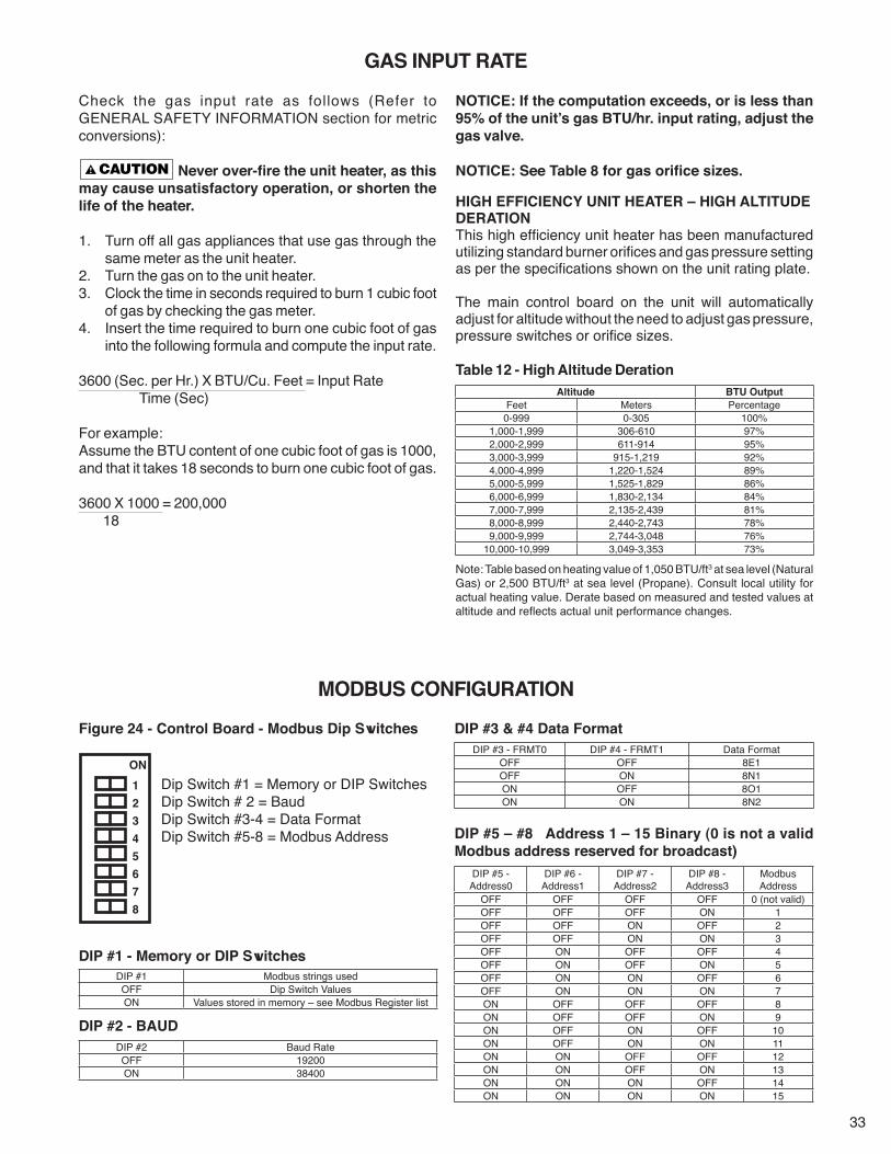
33
Check the gas input rate as follows (Refer to GENERAL SAFETY INFORMATION section for metric conversions):
Never over-fire the unit heater, as this may cause unsatisfactory operation, or shorten the life of the heater.
1. Turn off all gas appliances that use gas through the same meter as the unit heater.
2. Turn the gas on to the unit heater.3. Clock the time in seconds required to burn 1 cubic foot
of gas by checking the gas meter.4. Insert the time required to burn one cubic foot of gas
into the following formula and compute the input rate.
3600 (Sec. per Hr.) X BTU/Cu. Feet = Input Rate Time (Sec)
For example:Assume the BTU content of one cubic foot of gas is 1000, and that it takes 18 seconds to burn one cubic foot of gas.
3600 X 1000 = 200,000 18
GAS INPUT RATE
Altitude BTU OutputFeet Meters Percentage
0-999 0-305 100%1,000-1,999 306-610 97%2,000-2,999 611-914 95%3,000-3,999 915-1,219 92%4,000-4,999 1,220-1,524 89%5,000-5,999 1,525-1,829 86%6,000-6,999 1,830-2,134 84%7,000-7,999 2,135-2,439 81%8,000-8,999 2,440-2,743 78%9,000-9,999 2,744-3,048 76%
10,000-10,999 3,049-3,353 73%
NOTICE: If the computation exceeds, or is less than 95% of the unit’s gas BTU/hr. input rating, adjust the gas valve.
NOTICE: See Table 8 for gas orifice sizes.
HIGH EFFICIENCY UNIT HEATER – HIGH ALTITUDE DERATIONThis high efficiency unit heater has been manufactured utilizing standard burner orifices and gas pressure setting as per the specifications shown on the unit rating plate.
The main control board on the unit will automatically adjust for altitude without the need to adjust gas pressure, pressure switches or orifice sizes.
Table 12 - High Altitude Deration
Note: Table based on heating value of 1,050 BTU/ft3 at sea level (Natural Gas) or 2,500 BTU/ft3 at sea level (Propane). Consult local utility for actual heating value. Derate based on measured and tested values at altitude and reflects actual unit performance changes.
MODBUS CONFIGURATION
Figure 24 - Control Board - Modbus Dip Switches
DIP #1 - Memory or DIP Switches
DIP #2 - BAUD
Dip Switch #1 = Memory or DIP SwitchesDip Switch # 2 = BaudDip Switch #3-4 = Data FormatDip Switch #5-8 = Modbus Address
DIP #1 Modbus strings usedOFF Dip Switch ValuesON Values stored in memory – see Modbus Register list
DIP #3 - FRMT0 DIP #4 - FRMT1 Data FormatOFF OFF 8E1OFF ON 8N1ON OFF 8O1ON ON 8N2
DIP #5 - Address0
DIP #6 - Address1
DIP #7 - Address2
DIP #8 - Address3
Modbus Address
OFF OFF OFF OFF 0 (not valid)OFF OFF OFF ON 1OFF OFF ON OFF 2OFF OFF ON ON 3OFF ON OFF OFF 4OFF ON OFF ON 5OFF ON ON OFF 6OFF ON ON ON 7ON OFF OFF OFF 8ON OFF OFF ON 9ON OFF ON OFF 10ON OFF ON ON 11ON ON OFF OFF 12ON ON OFF ON 13ON ON ON OFF 14ON ON ON ON 15
DIP #2 Baud RateOFF 19200ON 38400
DIP #3 & #4 Data Format
DIP #5 – #8 Address 1 – 15 Binary (0 is not a valid Modbus address reserved for broadcast)
ON 1 2 3 4 5 6 7 8

34
PNEUMATIC TUBING TROUBLE SHOOTING SCHEMATIC
Figure 25 - Pneumatic Tubing Schematic
TO PRESSURETRANSDUCER LOW
TO PRESSURE TRANSDUCER
TO POWER VENTERPRESSURE SWITCH, HIGHPRESSURE TAP
FITTING ON FLUECOLLECTOR
TO BULK HEAD FITTING ONPARTION PANEL
TO GAS VALVE PRESSURE TAP ONSIZE 50-200 UNITS. CONNECTIONIS CAPPED ON SIZE 300 - 400 UNITS
3/16TO BLOCKED INLETPRESSURE SWITCH
CAT-10120C
TO POWER VENTERPRESSURE SWITCH,LOWPRESSURE TAP
MANIFOLD, AIR

35
SYMPTOMS POSSIBLE CAUSE(S) CORRECTIVE ACTIONA. Yellow tip flame (some
yellow tipping on LP gas is permissible).
1. Clogged air inlet filter.2. Clogged main burners.3. Insufficient combustion air.4. Possibly over fired.
1. Clean filter.2. Clean mesh burner.3. Insufficient combustion air.4. Check CO2.
B. Floating flame. 1. Insufficient combustion air.2. Air leak into combustion chamber or
inducer failure.
1. Clean combustion air inlet openings or filter.2. Determine cause and repair accordingly.
C. Gas odor. 1. Shut off gas supply immediately!2. Leaking port on valve.3. Blocked heat exchanger.4. Blocked flue collector.5. Negative pressure in the building.
1. Inspect all gas piping and repair.2. Check to ensure valve ports are seated.3. Clean heat exchanger/flue.4. Clean flue collector.5. See INSTALLATION.
D. Delayed ignition. 1. Improper ground.2. Bad or broken spark cable.3. Faulty control.4. Pressure regulator set too low.5. Main burner and/or orifice dirty.6. Improper venting.
1. Check grounding wires and spark bracket connections.2. Inspect spark cable connections and cuts.3. Check to ensure spark is energized after pre-purge period.4. Test and reset manifold pressure refer to OPERATION.5. Clean orifice or burners.6. Refer to INSTALLATION.
E. Failure to ignite. 1. Gas supply is off.2. No power supply to unit.3. Thermostat not calling.
4. Defective high limit.5. Defective drafter prove switch.
6. Loose wiring.7. Improper ground.8. Improper thermostat or transformer wiring.
9. Condensate trap clogged, leaking, or not installed.
10. Defective ignition control. 11. Cap off pressure tubing
1. Open all manual valves “check for leaks”.2. Turn on power supply, check fuses and replace if bad.3. Turn up thermostat, Check for 24V on terminals R and W1
on terminal strip.4. Check switch for continuity if open with no heat present,
replace.5. Check switch operation to ensure switch closes after
drafter purge period. If it does not make/check tubing connections/ blockage.
6. Check all wiring per diagram.7. Check all ground wires and connections. 8. Check both, for wiring according to diagram; check for
24V at gas valve terminals during trial for ignition period if present and valve does not open. Replace valve.
9. Clean condensate trap or install if not yet connected.
10. Replace ignition control 11. Re-install cap on tubing.
F. Burners will not shut off. 1. Thermostat located incorrectly.2. Improper thermostat wiring.
3. Shorted circuit.4. Defective sticking gas valve.
5. Excessive gas supply pressure.
1. Relocate thermostat away from outside wall or drafts.2. Check thermostat circuit for open and close on terminal
strip on heater “R” and “W”.3. Check thermostat circuit for shorts, staples piercing wires.4. Check for 24V on gas valve terminals when thermostat is
not calling.5. Refer to INSTALLATION.
G. Burner cycling. 1. Loose electrical connections at thermostat or gas valve.
2. Unit cycling on high limit.
3. Poor thermostat location.4. An improper ground.5. Condensate trap clogged, leaking, or not
installed.
1. Tighten all electrical connections.
2. Check for proper air supply across heat exchanger and proper gas supply.
3. Relocate thermostat.4. Refer to INSTALLATION.5. Clean condensate trap or install if not yet connected.
H. Noisy power venter. 1. Power venter wheel loose.2. Power venter wheel is dirty.3. Power venter wheel is rubbing on the
housing.
1. Replace or tighten.2. Clean power venter wheel.3. Realign power venter wheel.
I. Fan will not run. 1. Loose electrical connections.2. Defective motor or overload.
3. Defective control board.
4. Defective fan relay.
1. Check and tighten wires on fan circuit.2. Test for 115V on terminal ACB Heat and “L2” if voltage is
present replace motor.3. Test for 115V on terminal ACB Heat and “L2” on the control
board, if voltage is not present 45 seconds after trial for ignition replace board.
4. Check for 24 volts on terminals 24 and 0. Check for 115V on normally open relay contact when calling.
J. Fan motor turns on and off while burner is operating.
1. Motor overload protection is tripping.
2. Loose wiring or connection.3. Control board is defective.
1. Check motor amps against motor name plate, check voltage, replace if found defective.
2. Check for 115V between motor leads.3. Check terminal 24 and 0 for 24 volts. If voltage is not
constant, replace control board.
HIGH EFFICIENCY GAS-FIRED UNIT HEATER TROUBLESHOOTING GUIDE

36
SYMPTOMS POSSIBLE CAUSE(S) CORRECTIVE ACTIONK. Fan will not stop. 1. Control Board is in flame failure mode.
2. Fan improperly wired.3. Defective board.
4. Defective fan relay.
5. High limit trip.
1. Turn 115V power off to the unit, wait 10 seconds and reapply voltage to the unit.
2. Check wiring of fan circuit to wiring diagram.3. If unit is not calling for heat and board is not in a flash code
mode, replace board. 4. Check for 0 volts on terminals 24 and 0. Check for 0 on
normally open relay contact when calling.5. See High Limit Tripping in troubleshooting section.
L. Not enough heat. 1. Incorrect gas input.2. Heater undersized.
3. Thermostat malfunction.
4. Heater cycling on limit.
5. Incorrect orifice size.
1. Refer to OPERATION.2. Is the heater output sized correctly for heat loss of the
space. Has the space been enlarged.3. Check thermostat circuit, 24V on terminals “R” and “W” on
terminal strip.4. Check air movement across heat exchanger. Check
voltage and amps at the fan motor. Check gas input to ensure unit is not over fired. Check heat exchanger to ensure unit is not dirty.
5. Check orifice size, replace if undersized.M. Too much heat. 1. Unit is over fired.
2. Thermostat malfunction.
3. Heater runs continuously.
4. Control board configured for incorrect size.
1. Refer to OPERATION. Check orifice size. If too big replace.2. Check thermostat for operation, to ensure circuit open and
closes.3. Check wiring per diagram; check operation at the gas
valve, look for a short in thermostat circuit.4. Check control board dip switch configuration.
N. Cold air is delivered during heater operation.
1. Incorrect gas input.2. Air throughput too high.
1. Refer to OPERATION.2. Refer to OPERATION.
O. High limit tripping. 1. Unit is over fired.2. Air flow is low.
3. Defective switch.
4. Defective control board.
1. Burner orifices may be too large, verify and replace.2. Check for proper voltage, ensure fan blade is correct and
free of debris.3. Check operation of switch, did the switch open when unit is
running or is the switch open during start-up.4. Check for 24V on line side of the high limit. Constant
voltage should be recorded if not control board is suspect. Check flash code.
P. Power venter will not run.
1. Loose wiring or connections.
2. Motor overload is tripped or bad motor.
3. Bad control board.
1. Check all wring in the power vent circuit to ensure good connection, including “Neutral”.
2. Check for 115V between motor leads and check amp draw of motor. Replace if needed.
3. Check for continuous 115V on molex plug on inducer and neutral during call for heat. If not present and all checks are normal, replace.
Q. Power venter turns on and off during operation.
1. Power venter improperly wired.2. Motor overload cycling or defective motor.
3. Defective control board.
4. Unit not reaching proper delta pressure.
1. Check power venter circuit per wiring diagram.2. Check motor voltage and amp draw to motor name plate,
replace if motor found defective.3. Check for continuous 115V on terminal molex plug during
call for heat, replace board if found defective.4. Check pneumatic tubing and vent pipe for blockages.
Check condensate trap for proper seal.R. Power venter will not
stop.1. Power venter improperly wired.2. Main burner did not light on call for heat.3. Defective control board.
1. Check power venter circuit per wiring diagram.2. Heater is in lockout mode check flash code table for problem.3. No flash codes present along with no call for heat, replace
control board.S. Combustion Blower will
not run.1. Loose wiring or connections.
2. Motor overload is tripped or bad motor.
3. Defective control board.
1. Check all wring in the power vent circuit to ensure good connection, including “Neutral”.
2. Check for 115V between motor leads and check amp draw of motor. Replace if needed.
3. Check for continuous 115V between black and white wires on molex plug and neutral during call for heat. If not present and all checks are normal, replace.
T. Combustion Blower turns on and off during operation.
1. Combustion Blower improperly wired.2. Motor overload cycling or defective motor.3. Defective control board.
1. Check Combustion Blower circuit per wiring diagram.2. Check motor voltage and amp draw to motor name plate,
replace if motor found defective.3. Check for continuous 115V between black and white wires
on molex plug of combustion blower during call for heat, replace board if found defective.
U. Combustion Blower will not stop.
1. Combustion Blower improperly wired.2. Main burner did not light on call for heat.3. Defective control board.
1. Check Combustion Blower circuit per wiring diagram.2. Heater is in lockout mode check flash code table for problem.3. No flash codes present along with no call for heat, replace
control board.V. Flue Temperature
Switch tripping.1. Unit over fired.2. Blocked heat exchanger3. Blocked combustion air or flue vent pipe.4. Clogged heat exchanger coil.
1. Refer to operation section.2. Clean heat exchanger/flue collector.3. Clean combustion air or flue vent pipe.4. Clean heat exchanger coil fins.

37
No Cycling or appliance power or thermostat call for heat since appliance failure has occured.
Line voltage power can cause product damage, severe injury or death. Only a trained experienced service technician should perform this trouble-shooting.
1. Check the system thermostat to make sure it is calling for heat. (Do not cycle the thermostat on and off at this time.)2. Observe the LED indicator on the bottom panel of the unit (red or orange LED off indicates no faults); check and
repair system as noted in the chart below.
NOTICE: Air flow proving switch and power venter hose barbs must be free of any dust or debris at all times. Periodically check these openings and/or if any problems occur.
HIGH EFFICIENCY GAS-FIRED UNIT HEATER TROUBLESHOOTING WITH LED INDICATOR ASSISTANCE
LED STATUS INDICATES CHECK/REPAIRRed LED – Off No Faults Not Applicable.Red LED – Solid Ignition Lockout Fault 1. Gas supply off or gas supply pressure too low.
2. Flame Sense rod contaminated or loose wire.3. Gas valve switch is off or wires are not connected.4. Broken or cracked porcelain on either sensor or ignitor.
Red LED – 1 Flash Flue Limit Fault 1. Obstruction or restriction in combustion air inlet or flue outlet. 2. Unit is over-fired.3. Control board fault or faulty switch. 4. Power venter is not working properly or producing correct delta pressure.
Red LED – 2 Flash Rollout Switch Fault 1. Obstruction or restriction in combustion air inlet or flue outlet.2. Unit is over-fired.3. Control board fault or faulty switch.4. Power venter is not working properly or producing correct delta pressure.
Red LED – 3 Flash High Limit Switch Fault 1. Gas supply off or gas supply pressure too high.2. Unit is over-fired.3. Blocked heat exchanger.4. Power venter is not working properly.5. Fan motor(s) or switch(es) failure.
Red LED – 4 Flash Inlet Pressure Switch Fault 1. Obstruction or restriction in combustion air inlet.2. Tubing connection to switch is cracked or broken.3. Faulty power venter or switch. 4. Dirty or clogged filter; clean filter.
Red LED – 5 Flash Condensate Float Switch Fault 1. Obstruction or restriction in condensate system. 2. Float switch miswired or failure.3. If applicable, condensate pump miswired or failure.
Red LED – 6 Flash Flue Pressure Switch Fault 1. Obstruction or restriction in combustion air inlet or flue outlet. 2. Tubing is cracked, broken, or blocked by moisture or debris.3. Blocked heat exchanger.4. Power venter is not working properly or producing correct delta pressure.5. Faulty control board, pressure transducer, or switch.6. Condensate trap stuck open, broken, or not properly installed.
Red LED – 7 Flash User Interlock Fault 1. Open interlock; broken, or miswired connection.2. Faulty control board.
During the trial for ignition, if the unit lights then loses flame sense while in the hold period, the unit will cycle without a flash code. Check: flame sense rod for contamination, loose wire, or faulty ignition control board.
LED STATUS INDICATES CHECK/REPAIRRed LED – Solid Orange LED – 1 Flash
Pressure Transducer Fault 1. Tubing is cracked, broken, or blocked by moisture or debris. 2. Faulty transducer or control board.3. Power venter not working properly or producing correct delta pressure.4. Blockage in flue.
Red LED – Solid Orange LED – 2 Flash
Power Venter Fault 1. Power venter failure.2. Faulty control board.
Red LED – Solid Orange LED – 3 Flash
Combustion Blower Fault 1. Combustion blower failure.2. Faulty control board.
Orange LED – 1 Flash Open OA Sensor Warning 1. Check sensor is properly installed and wired.2. Sensor failure.
Orange LED – 2 Flash Shorted OA Sensor Warning 1. Check sensor is properly installed and wired.2. Sensor failure.
Orange LED – 3 Flash Open Space Sensor Warning 1. Check sensor is properly installed and wired.2. Sensor failure.
Orange LED – 4 Flash Shorted Space Sensor Warning 1. Check sensor is properly installed and wired.2. Sensor failure.
Orange LED – 5 Flash Open Stratification Sensor Warning
1. Check sensor is properly installed and wired.2. Sensor failure.
continued on the next page

38
MAINTENANCE Under no circumstances should
combustible material be located within the clearances specified in this manual. Failure to provide proper clearance could result in personal injury or equipment damage from fire.
2. Turn off the manual gas valve and electrical power to the unit heater.
3. To clean or replace the burners, remove burner mounting bracket nuts located in burner compartment. Disconnect union between gas valve and combustion blower. Lift burner assembly up and pull away from heat exchanger to remove.
4. To remove any dirt, dust, or other foreign matter from the burner box mesh, remove burner box cover plate and use compressed air to clean the mesh burners and inlet filter.
NOTICE: Do not use chemical cleaners. Chemical cleanersmay damage burner mesh or other components.5. Inspect inlet air distributor for any dirt, dust, or other
foreign matter. If required, remove using compressed air.6. The condensate trap can be cleaned by loosening the
union nut. The spring float should be cleaned of any debris.
7. Reassemble the unit heater by replacing all parts in reverse order.
8. Check all gas control valves and pipe connections for leaks.
Check all pipe joints for leakage using a soap solution or other approved method. Never use an open flame or severe personal injury or death may occur!
9. Check the operation of the automatic gas valve by lowering the setting of the thermostat, stopping the operation of the unit. The gas valve should close tightly, completely extinguishing the flame on the burners.
10. Inspect and service motor/fan assembly. To maintain efficient air flow, inspect and clean the fan blades and guard to prevent buildup of foreign matter.
11. Periodically check the finned surfaces of the heat exchanger; vacuum or use compressed air as often as necessary to remove any accumulation of lint and dirt.
PERIODIC SERVICENOTICE: The heater and vent system should be checked once a year by a qualified technician.
All Maintenance/Service information should be recorded accordingly on the GAS EQUIPMENT START-UP AND INSPECTION SHEET provided in this manual.
Open all disconnect switches, disconnect all electrical and gas supplies, and secure in that position before servicing unit. Failure to do so may result in personal injury or death from electrical shock.
Gas tightness of the safety shut-off valves must be checked on at least an annual basis. Failure to do so may result in death, serious injury or substantial property damage.
To check gas tightness of the safety shut-off valves:1. Turn off the manual valve upstream of the appliance
combination control.2. Turn set screw of test port on gas valve counter
clockwise and connect a manometer to that tapping.3. Turn the manual valve on to apply pressure to the
combination control.4. Note the pressure reading on the manometer, then
turn the valve off.5. A loss of pressure indicates a leak. If a leak is detected,
use a soap solution to check all threaded connections.6. If no leak is found, combination control is faulty and must
be replaced before putting appliance back in service.
NOTICE: See separate operation manuals provided with any unit accessories for their maintenance/service requirements.
Should maintenance be required, perform the following inspection and service routine:1. Inspect the area near the unit to be sure that there is
no combustible material located within the minimum clearance requirements listed in this manual.
HIGH EFFICIENCY GAS-FIRED UNIT HEATER TROUBLESHOOTING WITH LED INDICATOR ASSISTANCE (continued)
LED STATUS INDICATES CHECK/REPAIROrange LED – 6 Flash Shorted Stratification Sensor
Warning1. Check sensor is properly installed and wired.2. Sensor failure.
Orange LED – Solid Stratification Mode On Not Applicable
NOTICE: For Rollout Switch Fault, the rollout switch must be manually reset before unit operation can resume. If a Red LED-2 Flash is observed, the red button on the rollout switch will have to be depressed to reset. This switch is located on the top of the burner compartment. The red button should be depressed until an audible "click" is heard.NOTICE: For Stratification Sensor Warnings, the stratification sensor wires can be removed from the control board and the unit power cycled to allow unit to function normally without stratification mode. Once sensor has been replaced (and re-wired), the unit will auto-detect the sensor and allow stratification operation.

39
LIMITED WARRANTYHigh Efficiency Propeller Unit Heaters
1. The "Manufacturer" warrants to the original owner at original installation site that the above model Gas-Fired Heater ("the Product") will be free from defects in material or workmanship for (1) year from the date of shipment from the factory, or one and one-half (1-1/2) years from the date of manufacture, whichever occurs first. The Manufacturer further warrants that the complete heat exchanger, flue collector, and burners be free from defects in material or workmanship for a period of ten (10) years from the date of manufacture. If upon examination by the Manufacturer the Product is shown to have a defect in material or workmanship during the warranty period, the Manufacturer will repair or replace, at its option, that part of the Product which is shown to be defective.
2. This limited warranty does not apply: a. if the product has been subjected to misuse or neglect, has been accidentally or intentionally damaged, has
not been installed, maintained, or operated in accordance with furnished written instructions, or has been altered or modified in any way by any unauthorized person.
b. to any expenses, including labor or material, incurred during removal or reinstallation of the Product. c. to any damage due to corrosion by chemicals, including halogenated hydrocarbons, precipitated in the air. d. to any workmanship of the installer of the Product.
3. This limited warranty is conditional upon: a. advising the installing contractor, who in turn notifies the distributor or Manufacturer. b. Shipment to the Manufacturer of that part of the Product thought to be defective. Goods can only be returned
with prior written approval of the Manufacturer. All returns must be freight prepaid. c. determination in the reasonable opinion of the Manufacturer that there exists a defect in material or
workmanship.
4. Repair or replacement of any part under this Limited Warranty shall not extend the duration of the warranty with respect to such repaired or replaced part beyond the stated warranty period.
5. THIS LIMITED WARRANTY IS IN LIEU OF ALL WARRANTIES, EITHER EXPRESS OR IMPLIED, AND ALL SUCH OTHER WARRANTIES, INCLUDING WITHOUT LIMITATION IMPLIED WARRANTIES OF MERCHANTABILITY OR FITNESS FOR A PARTICULAR PURPOSE, ARE HEREBY DISCLAIMED AND EXCLUDED FROM THIS LIMITED WARRANTY. IN NO EVENT SHALL THE MANUFACTURER BE LIABLE IN ANY WAY FOR ANY CONSEQUENTIAL, SPECIAL, OR INCIDENTAL DAMAGES OF ANY NATURE WHATSOEVER, OR FOR ANY AMOUNTS IN EXCESS OF THE SELLING PRICE OF THE PRODUCT OR ANY PARTS THEREOF FOUND TO BE DEFECTIVE. THIS LIMITED WARRANTY GIVES THE ORIGINAL OWNER OF THE PRODUCT SPECIFIC LEGAL RIGHTS. YOU MAY ALSO HAVE OTHER RIGHTS WHICH MAY VARY BY JURISDICTION.
In the interest of product improvement, we reserve the right to make changes without notice.

40
IDENTIFICATION OF PARTS
Figure 27 - Flue Collector/Drafter Assembly
Figure 28 - Air Gas Inlet Assembly
Figure 26 - Component Access
CAT-10089A
FLUE COLLECTOR GASKET
DRAFTER MOUNTING PLATE
SELF-DRILL SCREW, #8-18
INDUCER
THREADED HEX INSERT, #10-24
FLUE COLLECTOR ASSEMBLY
DRAFTER GASKET
CAT-10085AMACHINE SCREW, #10-24
MACHINE SCREW, #6-32
AIR-GAS INLETCOVER PLATE
INLET AIRDISTRIBUTOR
MACHINE SCREW, (3) M4x6 & (3) M6x6
COMBUSTION BLOWER
NUT, FLANGED, 1/4-20
COMBUSTION BLOWER GASKET
O-RING
HEX NUT,SERRATED FLANGE,1/4-20
CAT-10088B

41
Figure 29 - Heat Exchanger Components
Figure 30 - Propeller Motor/Fan Assembly
HOW TO ORDER REPLACEMENT PARTS
Please send the following information to your local representative: if further assistance is needed, contact the manufacturer's customer service department.• Unit Number• Serial Number• Part Description and Number as shown in Replacement parts Catalog
TURBULATOR
COMBUSTION TUBE
COMBUSTION VESTIBULEPANEL
TURN VESTIBULE PANEL
TURN COVER GASKET
TURN COVER
COIL ASSEMBLY
CAT-10086B
MOTOR
HARDWARE
RUBBER GROMMET
OSHA FAN GUARD
OSHA FAN GUARD PLATE
HARDWARE
FAN BLADE
CAT-10079A
SNAP BUSHING 1-1/8"
CONTROL BOARD
SNAP BUSHING 3/4"
PRESSURE SWITCH, POWER VENTER
PRESSURE SWITCH, BLOCKED INLET
PRESSURETRANSDUCER
LED INDICATOR, ORANGE
LED INDICATOR, RED
RELAY, SPDT115, 24V
RELAY BRACKET
CAT-10121B
Figure 31 - Control Box Components

42
APPENDIX A – MODBUS REGISTERS
Address Name Raw Data Type Scale Description Valid Values/Range
40001 Modbus Address 8 bit unsigned – This Modbus Address is used if the Communications settings location DIP is set to Memory 1 - 247
40002 Modbus Baud 8 bit unsigned – This Modbus Baud is used if the Communications settings location DIP is set to Memory
0 = 12001 = 24002 = 48003 = 96004 = 192005 = 384006 = 568007 = 57600
40003 Modbus Data Format 8 bit unsigned – This Modus Data Format is used if the Communications settings location DIP is set to Memory
0 = 8E11 = 8O12 = 8N23 = 8N1
40004 Modbus Mode 8 bit unsigned –Modbus Mode. (see BMSTimer)If no wired operating mode demands are present, setting the state member of this variable will put the unit in the corresponding mode.
0 = Standby1 = Fan Only (G)2 = Heating 1 (W1)3 = Heating 2 (W2)
40005 Modbus Input 8 bit unsigned 1.0
Modbus Input (see BMSTimer)If no wired operating mode demands are present, and the unit is operating per the Modbus Mode variable, the unit will run at this input.
Note – Writing 0 to this variable will allow the unit to run at the input dictated by its local settings.
33% - 100%
0 – Local Control
40006 BMS Timer 16 bit unsigned –
BMS Timer
The BMS timer is a BMS failsafe feature. This countdown timer should be periodically reloaded with a timeout value (in seconds). If the timer reaches zero, the control assumes that the BMS is no longer operating, and clear the Modbus Mode and Modbus Input values. This is a failsafe feature used to help safeguard the system in case of BMS failure.
When any Read/Write variable is written, if the BMS Timer is less than 60, it is automatically reloaded with 60.
Writing 0 to the BMS Timer will disable this feature.
Writing non 0 values to this the BMS Timer enables this feature.
Default is ON
0 – 65535 seconds
Input/Output Variables (Read/Write)

43
Address Name Raw Data Type Scale Description Valid Values/Range
30001 Outside Temperature 16 bit unsigned 1.0 Outside air temperature * optional
-40 – 250°F-52°F if not installed
30002 Space Temperature 16 bit unsigned 1.0 Space temperature * optional
-40 – 250°F-52°F if not installed
30003 Strat Temperature 16 bit unsigned 1.0 Stratification temperature * optional
-40 – 250°F-52°F if not installed
30004 Delta Pressure 16 bit unsigned 0.01 Pressure across the unit 0 – 5 ‘WC
30005 Ignition State 8 bit unsigned – Current Ignition State of the unit
0 = Standby1 = Sequence Start2 = Pre Purge3 = Ignition Trial4 = Running5 = Post Purge6 = Lockout
30006 Operating Mode 8 bit unsigned – The current operating mode of the unit.
0 = Standby1 = Fan Only (G)2 = Heating 1 (W1)3 = Heating 2 (W2)
30007 Operating Input 8 bit unsigned 1.0 The current operating input of the unit. 33% - 100%
30008 Prop Fan 8 bit unsigned – Unit Prop Fan Status 0 = Prop Fan Off1 = Prop Fan On
30009 Thermostat Inputs Status 8 bit unsigned – These bits indicate the state of the thermostat inputs. See the Thermostat Inputs Flags table.
30010 Indoor Air Reset 8 bit unsigned 1.0 Current Indoor Air Rest Limit 33% – 100%30011 Fault Code 8 bit unsigned – Indicates the highest priority Fault set on the unit. See the Fault Code Table.30012 Inducer Blower RPM 16 bit unsigned 1.0 Current RPMs of the inducer blower 0 – 650030013 Combustion Blower RPM 16 bit unsigned 1.0 Current RPMs of the Combustion blower 0 – 11300
Bit Description Valid Values/Range0 Thermostat G (Local or Global) 0 = No Signal, 1 = Signal Present1 Thermostat W1 (Local or Global) 0 = No Signal, 1 = Signal Present2 Thermostat W2 (Local or Global) 0 = No Signal, 1 = Signal Present3 Thermostat AUX (Local or Global) 0 = No Signal, 1 = Signal Present4 Reserved Reserved5 Reserved Reserved6 Reserved Reserved7 Reserved Reserved
Error Code Description0 No Fault or Warning
Faults – The unit cannot run1 Flue Limit Switch Trip2 Roll Out Switch Trip3 High Limit Trip4 Inlet Pressure Switch Trip5 Condensate Float Switch Trip6 Flue Pressure Switch Error7 User Interlock Trip8 Pressure Transducer Error9 Inducer Blower Fault
10 Combustion Blower Error11 Ignition Lockout Error12 Blower Lockout Error
Warnings – The unit can run20 Open Outside Air Temperature Sensor21 Shorted Outside Air Temperature Sensor22 Open Space Temperature Sensor23 Shorted Space Temperature Sensor
Input Variables (Read Only)
Status Flags – Thermostat Input Flags
System Fault/Warning Codes

44
HIGH EFFICIENCY GAS-FIRED UNIT HEATERUNIT NUMBER DESCRIPTION
DIGIT N X X X – 1 2 3 4 5 6 7 8 9 10 11 12 13 14 15 +
ITEM PREFIX UT CA FT FM GT AL GC SV MT MS DL AS(Internal Use Only)
1, 2 - Unit Type [UT]HU/BH - High Efficiency Unit Heater
3, 4, 5 - Capacity [CA]050 - 50,000 BTU/HR100 - 100,000 BTU/HR150 - 150,000 BTU/HR200 - 200,000 BTU/HR300 - 300,000 BTU/HR400 - 400,000 BTU/HR
6 - Furnace Type [FT]A - Right Side Access
7 - Heat Exchanger (Furnace) Material [FM]1 - Stainless Steel Tubes with Aluminum and Brass FinsNote: Stainless Steel Flue Collector is standard.
8 - Gas Type [GT]N - Natural GasP - Propane Gas (LP)
9 - Altitude [AL]S - 0–11,999 ft.Note: Installations over 2,000 ft. require gas input deration in the field. Refer to unit installation instructions.
10 - Direct Spark Gas Control [GC]1 - Modulating w/Outside Air Reset (Master)2 - Modulating w/Outside Air Reset (Network)3 - Modulating w/Indoor Air Reset4 - Modulating w/2-10 VDC/4-20 mA Input5 - Modulating w/Room Sensing6 - Two Stage
11 - Supply Voltage [SV]1 - 115/1/60 5 - 230/3/602 - 208/1/60 6 - 460/3/603 - 230/1/60 7 - 575/3/604 - 208/3/60 Z - SpecialNote: Supply Voltages [SV] 2-7 include field mounted step down transformer.
12 - Motor Type [MT]1 - Open Drip Proof
13 - Blower Motor Sizes [MS]0 - Not applicable
14 - Design Level [DL]B - Second design level
15+ - Accessories [AS]0 - Not applicable
† FIELD INSTALLED (AS-____ )† All Field Installed Accessories are to be entered as a separate line item using the catalog number which utilizes “11AS” as a prefi x. i.e: G3 becomes 11AS-G3.
A7 - High Pressure Regulator A7-1/2-1 - Regulator for PSI range 0.5-10 A7-3/2-1 - Regulator for PSI range 10-20 A7-5/16-1 - Regulator for PSI range 20-35 E9 - Condensate Neutralizer (Inline)EW - Condensate Neutralizer (Wall Mounted)
G1 - 1-Stage Mercury Free Thermostat (Round)G2 - 1-Stage Mercury Free Thermostat w/Guard KitG3 - 1-Stage Mercury Free Thermostat w/Fan SwitchG5 - 2-Stage Mercury Free Thermostat w/Fan SwitchG6 - Locking Thermostat CoverG9 - 1-Stage Mercury Free Heating Only ThermostatGW - WiFi Thermostat TH8321WF1001/U
H9 - Stratification Sensor
K8 - Condensate PumpK9 - Condensate Pump Shelf
Y2 - 2" PVC Concentric Vent KitY3 - 3" PVC Concentric Vent KitY4 - 4" PVC Concentric Vent Kit

45
Customer ____________________________________ Job Name & Number _________________________
PRE-INSPECTION INFORMATIONWith power and gas off.
Type of Equip: Unit Heater
Serial Number _________________________ Model Number __________________________Name Plate Voltage: _____________ Name Plate Amperage: _____________Type of Gas: Natural LP Tank Capacity _______ lbs. Rating: _ _____ BTU @ ____ °F _______ kg _ _____ kw @ ____ °C❐ Are all panels, doors, vent caps in place?❐ Has the unit suffered any external damage? Damage ______________________________❐ Does the gas piping and electric wiring appear to be installed in a professional manner?❐ Has the gas and electric been inspected by the local authority having jurisdiction?❐ Is the gas supply properly sized for the equipment?❐ Were the installation instructions followed when the equipment was installed?❐ Have all field installed controls been installed?❐ Do you understand all the controls on this equipment? If not, contact your wholesaler or rep. (DO NOT START this equipment unless you fully understand the controls.)
GAS EQUIPMENT START-UP AND INSPECTION SHEET
GENERALWith power and gas off.
❐ Make certain all packing has been removed.❐ Tighten all electrical terminals and connections.❐ Check all fans & blowers for free movement.❐ Check all controls for proper settings.
FANWith power and gas off.
❐ Check voltage L1___ L2___ L3___❐ Check rotation of main fan.❐ Check motor amps L1___ L2(N)___
Remarks: _________________________________________________________________________________________________________________________________________________
GAS HEATINGWith power and gas on.
❐ Inlet gas pressure. ____ in. W.C. or ____ kPa❐ Burner ignition.❐ Cycle and check all other controls not listed.❐ Entering air temp. _____ °F or ____ °C❐ Discharge air temp. (High Fire) ____ °F. or ____ °C❐ Cycle by thermostat or operating control.❐ Combustion Readings (High Fire): Carbon Monoxide:____ PPM Carbon Dioxide:____ % O2:____ %❐ Combustion Readings (Low Fire): Carbon Monoxide:____ PPM Carbon Dioxide:____ % O2:____ %

46

47

260 NORTH ELM ST., WESTFIELD, MA 01085TEL: (413) 564-5540 FAX: (413) 562-5311www.mestek.com